Operating and Assembly Instructions
|
|
|
- Mervyn Parrish
- 6 years ago
- Views:
Transcription
1 Operating and Assembly Instructions Model: LOTUS 1

2 Copyright and Trademark Copyright 2015 uwe Light GmbH This documentation only covers products manufactured by uwe Light GmbH. It must not be duplicated, photocopied, translated or stored without prior special consent by uwe Light GmbH. Duplication on electronic media or in a machine-readable form, either in whole or in part, is also prohibited. is a registered trademark of uwe Light GmbH DISCLAIMER All information given in this document corresponds to the status quo at the date of publication but may be subject to changes. Therefore, we do not accept any liability for, nor do we guarantee the accuracy and/or completeness of the information. EXPORT Technical equipment and versions of the devices are in accordance with the legal prescriptions of the respective country of destination. Export to the European Union of the uwe products, listed in this guide, or operation of the systems in these countries, are not permitted. uwe does not accept any manufactures liability in case this direction is not adhered to. It is expressly pointed out that any violation of the export/operation prohibition will involve substantial risks of liability for the exporter and/or operator. MANUFACTURER uwe Light GmbH Buchstraße Schwäbisch Gmünd Germany CONTACT PC Tan 1040 Wilt Avenue Ridgefield, NJ USA FAST TAN ( ) Document version date: December,
3 Contents 1. General information 1.1 About these instructions 1.2 Safety signs 1.3 Transport by forklift truck 1.4 Other modes of transport 1.5 Environmental regulations 1.6 Service 1.7 Updating system software 2. Safety notes 2.1 General safety notes 2.2 Duties of the operator 2.3 Intended use 2.4 Indications for use 2.5 Contraindications 2.6 Warnings 2.7 Remote timer controlled operation 2.8 Guidelines for the use of protective eyewear 3. Description of the tanning device 3.1 Standards 3.2 Components 3.3 Functionality 4. Connections 4.1 Class I ME equipment 4.2 Overview - supply connections 4.3 Connecting the mains voltage 4.4 Connecting an external audio source 4.5 Studio music signal 4.6 Operation using different audio sources 4.7 Remote control timer operation 4.8 T-Max Connection (External and internal timer) 4.9 Aroma connections - Not Applicable 4.10 Breeze connections - Not Applicable 5. Start-up 5.1 Operating modes 6. Tanning instructions 6.1 Instructions for the user 6.2 Exposure schedule 3
4 7. Tanning mode 7.1 Starting the tanning session in remote control mode 7.2 Basic functions 8. Service menu 8.1 Service module 8.2 Operating the service module 8.3 Service module menu 8.4 Pre-set service intervals 8.5 Overview of possible setting 8.6 Service menu diagram 8.7 Set decorative lighting 9. Maintenance and cleaning 9.1 Instructions for cleaning and care 9.2 Maintenance intervals 9.3 Acrylic panes 9.4 Facial tanners 9.5 Sunlamps 9.6 Filter mats 9.7 Breeze - Not Applicable 9.8 Aroma - Not Applicable 10. Assembly Instructions 10.1 Delivery condition 10.2 Disassembly of the unit 11. System messages 11.1 System messages 11.2 Tips for Troubleshooting 12. Technical data 12.1 Views 12.2 Labels attached to the tanning device (examples) 13. uwe EQUIPMENT WARRANTY 14. WARRANTY CARD 15. EMC Information 4


5 1. General information 1.1 About these instructions This operating manual is intended for use by - Operator & staff > Persons responsible for the operation, disinfecting, cleaning and maintenance work and instructs the user in the operation of the device. - User > A person who uses the tanning device at a commercial facility. - Service provider > Qualified outside service company authorized by the manufacturer for assembly, maintenance and repair work. Any person dealing with this uwe Sunlamp Product (hereafter referred to as tanning device) must have read and understand these instructions. This manual describes tanning devices equipped with the maximum number of features. Keep this manual readily available at all times. 1.2 Safety signs and symbols 5

6 1.3 Transport by forklift truck - The tanning device is mounted on a pallet. - Insert the forks carefully into the openings of the pallet. - Lift the load by a few inches. - Transport the load carefully to the place of installation. 1.4 Other modes of transport If a forklift truck cannot be used for transport, the tanning device must be partially disassembled and the parts must be transported individually to the place of installation, e.g. using a dolly. Depending on the weight of the components, lifting them might require several people. 1.5 Environmental regulations (disposal of lamps) Fluorescent lamps contain fluorescent materials and other waste products containing mercury. Some areas of the USA and Canada have specific regulations regarding disposal of these waste. Please check the laws in your area and act in accordance with municipal waste regulations. Please retain proof of proper disposal of lamps. Your local regulatory agency can assist you with the disposal of lamps. Report the number of lamps to your local agency by telephone or in writing. The regulatory agency can provide you with a delivery point for your lamps or will take care, in conjunction with a disposal company, of the collection and proper disposal of the lamps (Fees for this may apply). Please contact your code enforcement officials for more information regarding laws governing disposal of these components in your area. 6

7 1.5.1 Disposal of consumable supplies Dispose of AQUA SYSTEM and AROMA containers and their contents according to the national waste disposal laws and in accordance with the municipal waste regulations. 1.6 Service REPAIRS - SERVICE - REPLACEMENT - PARTS AND LAMPS - EYE PROTECTION If you are in need of any of the above mentioned products or services, you should contact: PC Tan 1040 Wilt Avenue Ridgefield, NJ 07657, USA FAST TAN ( ) NOTE: All repairs and replacement components including, but not limited to protective eyewear, lamps, timers and acrylic must be in compliance with CFR Technical documentation like operating and assembly instructions as well as diagrams and original spare parts can be provided by uwe Light GmbH. WARNING: No modification of this equipment is allowed. 1.7 Updating system software Software Update is only possible by uwe 7
8 This product is in conformity with performance standards for sunlamp products under 21 CFR DANGER--Ultraviolet radiation. Follow instructions. Avoid overexposure. As with natural sunlight, overexposure can cause eye and skin injury and allergic reactions. Repeated exposure may cause premature aging of the skin and skin cancer. WEAR PROTECTIVE EYEWEAR; FAILURE TO MAY RESULT IN SEVERE BURNS OR LONG-TERM INJURY TO THE EYES. Medications or cosmetics may increase your sensitivity to the ultraviolet radiation. Consult physician before using sunlamp if you are using medications or have a history of skin problems or believe yourself especially sensitive to sunlight. If you do not tan in the sun, you are unlikely to tan from the use of this product. Product meets requirements of UL standard 482, CSA C22.2 No. 224 and EMC standard IEC : Safety notes 2.1 General safety notes Read the operating instructions before using the tanning device. This tanning device must be operated with an external timer as specified in chapter 2.7 Remote timer controlled operation. When the device is in use no other people may remain in the room. This includes both children and adults. NOTE: This tanning device is intended to be used by only one adult person at a time. Therefore, only one (1) pair of protective eyewear is provided with each uwe tanning device. Use protective eyewear whenever the tanning device is operated. Read related operating instructions in chapter2.8 Guidelines for the use of protective eyewear. Do not tan more than once in a 24 hour period. Tanning results normally occur after a few sessions and increase after four (4) weeks of regular exposure. Follow the exposure schedule in accordance with your skin type as specified in chapter 6.2 Exposure schedule. Failure to do so may result in overexposure. However, regardless of how dark an individual may tan on this tanning device, it will not provide adequate protection against overexposure to natural sunlight or UVB tanning devices. 8

9 SKIN TYPE II - This is the individual that usually burns easily and severely, tans minimally or lightly and peels. SKIN TYPE III - Often referred to as AVERAGE complexion. Burns moderately and tans about average. SKIN TYPE IV - This individual burns minimally, tans easily and above average with each exposure. SKIN TYPE V - This individual rarely burns, tans easily and substantially. Follow all instructions given in this manual. In addition to that, observe all applicable statutory provisions and regulations, also those applicable in the country of operation. The device may only be installed and assembled by a trained service provider. Observe all danger signals and safety signs attached to the equipment. Safety signs must not be removed, and safety appliances must not be disabled. The tanning device may only be operated when in perfect working condition. Never operate the tanning device with the outer covering removed or with the acrylic panes removed. Pay attention to the load limit of the bed pane (tanning bed devices only). The canopy is not designed to carry additional loads. In particular, during installation the canopy must not be charged with additional loads. Caution Use of controls or adjustments or performance of procedures other than those specified herein may result in hazardous radiation exposure. Equipment not suitable for use in the presence of a flammable anesthetic mixture with air, oxygen, or nitrous oxide. The solvents of adhesives and flammable solutions used for cleaning and disinfecting should be allowed to evaporate before the unit is used. 2.2 Duties of the operator - Inform users of the possible risks of tanning. - Responsible to ensure the tanning device is handled properly and may only be used when in complete operational condition. - Ensure no safety component is removed or bypassed to impair the safe operation of the device. - Obligated to train your personnel and ensure your staff understands and observes the operating instructions, including intended use, safety and cleaning/disinfection and maintenance instructions. - Please make all instructions available to your staff at their workplace. 9

10 The manufacturer cannot be held liable for damages or injuries resulting from improper use of the equipment or non-observance of these operating instructions. 2.3 Intended use This tanning device is intended for the cosmetic tanning of the human skin. This tanning device is designed for use by one adult person at a time who is in full command of her physical, sensorial and mental faculties. Moreover, sufficient knowledge and experience are required. Wear protective eyewear to block UV radiation during tanning. Lie down on the bench in a straight position and with physical contact to the bench. Choose a suitable position to reach the interior control panel at all times during the tanning. During the operation no other person shall be in the radiation range of the tanning device. 2.4 Indications for use Any adult person that is not listed under Chapter 2.5 Contraindications may use this tanning device for the purpose of cosmetic tanning. In doubt consult a physician. 2.5 Contraindications This sunlamp product is contraindicated for use on persons under the age of 18 years. Danger of skin and eye injuries or skin diseases! Please observe the following instructions. This sunlamp product must not be used - if skin lesions or open wounds are present. - by persons wearing heart pacemakers. - by persons prone to sunburn (skin type I). - by persons already suffering from sunburn. - by persons taking medicines. - by persons taking photosensitive medications. - by persons, who had several severe sunburns as children. - by persons, who are being treated by a physician for conditions associated with photosensitivity. - by persons, who are prone to freckles. - by persons with atypical discolored skin areas or/and with more than five atypical moles with a diameter of 5 millimeters or more and persons with more than 16 moles with a diameter greater than or equal to 2 millimeters. If in doubt, consult a physician! - by persons with naturally red hair color. - by persons, who do not tan at all or cannot tan without getting sunburn. 10
11 2.6 Warnings - This sunlamp product should not be used on individuals who have had skin cancer or have a family history of skin cancer. - Persons repeatedly exposed to ultraviolet sunlamp products should be regularly evaluated for skin cancer. - The unit incorporates special preventive measures with regard to the electromagnetic compatibility and must be installed and commissioned according to the EMC instructions obtained from the assembly instructions. 2.7 Remote timer controlled operation This tanning device must be operated with an external timer that is listed in compliance with UL917. If the external timer fails, the tanning device is automatically switched off by an internal timer after the TE-time of the respective type of tanning device. The maximum tanning time must not be exceeded. 2.8 Guidelines for the use of protective eyewear Before use, the length of the elastic strap must be adjusted to the required head size. For maximum protection to alleviate stray light, the eye protection must fit securely and comfortably on the eyelids. If any stray light from the sides or under the rim of the lens, DO NOT USE this eye protection. Ask the salon staff to recommend an alternative eye protection. Never use eye protection lenses that are broken, cracked, bleached out, or otherwise damaged. 3. Description of the tanning device 3.1 Standards This product is in conformity with performance standards for sunlamp products under No. 21 CFR , UL 482, CSA C22.2 No. 224 and EMC standard IEC : Ed. 3, Components Applied parts are: Handle, acrylic patient support, shoulder tanner control panel. The tanning device basically consists of the following components: Not every model is equipped with all of the options described here and therefore: 1. Please observe the instructions which apply to your unit. 2. Please pass on all information to the user. 11
 after switching off the unit in order to cool it down.")
12 INTERACTIVE OPERATION You can regulate the tanning intensity and cooling for your body and face separately. FAN The fans continue to run for about 4 minutes (factory setting) after switching off the unit in order to cool it down. BREAKSAFE (unit type XTT) The filter discs above the high pressure lamps are protected by a BREAKSAFE device. If one of these filter discs breaks, the power is cut off and the unit can only be restarted after the filter disc has been replaced. SERVICE MODULE The service module allows you to monitor the operating hours according to the total operating hours of the tanning bed, the operating time of the High pressure lamps. The service module facilitates maintenance and inspections of parts for wear (see Ch. 5). AUDIO SYSTEM (T-MAX AUDIO amplifier optional) The unit may be connected to an external sound system. CONNECTION TO MP3 PLAYER, IPOD AND CELL PHONE The bed has a connection for your MP3 Player, ipod and your cell phone with which you can hear your own music. LOUDSPEAKER The tanning bed has two speakers allowing you to enjoy the music played on the central sound system while you tan. 4. Connections 4.1 Class I ME equipment 12

13 4.3 Connecting the mains voltage Electrical Requirements The unit is not delivered with a power cable for connection. The three-phase current cable must be installed by a licensed electrician. The appropriate wiring diagram is supplied with every unit. WARNING: To avoid the risk of electric shock, this equipment must only be connected to a supply mains with protective earth. 1. Install a separation device in the permanently fixed electrical installation to separate the mains power with a contact opening of at least 3 mm on each pole. The external construction like the fuses, main switch, fault current circuit breaker, have to be arranged by the owner/operator according to be local regulations. Fuse, earth leakage circuit breaker and main switch are to be installed as per local regulations. CONNECTION REQUIREMENTS The electrical installation must be equipped with a freely accessible all-pole disconnecting device in accordance with the overvoltage category III. (Master switch with clearly marked on/off settings e.g. O and I or additional indicator light). This means that for full separation each pole must have a contact gap according to the conditions of the overvoltage category III. The device shall be capable of being locked in the off-position and shall comply with IEC A supply main switch must not be incorporated in the power supply cord. A Class-A ground fault circuit interrupter (GFCI) has to be used for Canada. Should the operation of the tanning device cause any interference in the power supply network, e.g. with ripple-control systems (TRA), consult your power supply company to have corresponding blocking elements (audio frequency suppressors) installed. 13

14 The tanning device is set up to operate on 3 phase operation. 3- Phase Operation (3 x 220V / 60Hz) WARNING : Use only approved external devices to be connected to audio source. When FUNCTIONAL CONNECTION between the Tanning Bed and other items to be connected to the equipment can cause the allowable values of LEAKAGE CURRENT to be exceeded, then safety measures incorporating a SEPARATION DEVICE shall be applied. Contact PC Tan in case of doubt. 14

 Connection Line-In.")
15 4.4 Connecting an external audio source On the right side of the bed, a connection plate for an external audio system is located through which a non-amplified audio signal can be fed. 4.5 Studio music signal The music input signal must be a non-amplified signal. If the music input signal is amplified, it should be reduced with a high low level adapter. Adjustment of the sound level can only be conducted in the service menu Pr8 & Pr Operation using different audio sources The tanning device can be operated using the following audio sources: - External audio sources - Line-In (MP3 Connection) Connection Line-In. External players as MP3 players, mobile phones (cell phones), I-pods, etc. 4.7 Remote control timer operation The unit is configured for remote timer operation upon delivery from the factory. If the unit is to be operated privately, you must prepare the unit for private operation prior to the initial commissioning. To do this, a jumper must be repositioned on the mounting plate (behind the front apron). Power down the unit and protect against accidentally being switched back on! The unit is configured for remote timer upon delivery from the factory. 4.8 T-Max Timer (External Timer) The unit may only be connected by a qualified electrician in accordance with the appropriate national norm. 15
16 Power down the unit. The T-Max cable (66/2, 10 meters long) is supplied with every unit. Insert the plug (66/3) of the T- Max cable into the T-Max adapter (66/4) of the control board. Feed the cable through the recess (32/7) of the base outside and connect the cables at the T-Max Timer (66/1). Refer to the connections of the table in picture 66. The wiring diagram of the T-Max Timer see picture 67 and 68. Information about T-Max operation can be found within the T-Max guide, which is supplied with every T-Max Timer. 16
17 4.9 Aroma connections - Not Applicable 4.10 Breeze connections - Not Applicable 5. Start-up Before switching on for the first time: - Determine the pre-settings for the device in the service menu. - Check correct installation of fluorescent tubes. The tube labeling must be visible, otherwise no tanning effect may be obtained. - Store these Operating Instructions in a place that allows for easy access at any time. 5.1 Operating modes The three different operating modes are explained below: STANDBY MODE The tanning device is in an idle state, i.e. it is connected to the mains but is currently not being used. The tubes and the tanning lamps are switched off. From the standby mode, you can access the service menu. TANNING MODE The tubes and the tanning lamps are switched on and a tanning session is in progress. While the tanning device is in tanning mode, the settings for the ongoing tanning session can be 4changed via the interior control panel. FAN RUN-ON After the tanning session, the fan runs on for 4 minutes in order to cool down the device. 6. Tanning instructions Tanning normally begins after one to two exposures and maximizes after one to four (1-4) weeks of exposure following the recommended schedule for your skin type. NO SUNSCREEN WITH PROTECTION FACTOR Sunscreens with sun protection factors are unsuitable for use in a tanning salon. For tanning, the skin should have been thoroughly cleaned and be dry. For optimum skin care, we recommend using our line of body care products after tanning. 17
18 6.1 Instructions for the user Observe the following tanning instructions. GENERAL - Only the individuals described in the chapter 2.4 Indications for use may use the tanning device. - The different skin types tolerate the sun and hence tanning times to a different degree. Please observe the specifications in the skin-type table (supplied with the tanning device) and the tanning times. After having reached the ultimate tan, further tanning can only be achieved by substantially exceeding the allowed tanning times. This must absolutely be avoided. - The UV radiation of the sun or of UV appliances can cause damage to the skin or to the eyes. These biological effects depend on the type and amount of radiation as well as on the individual sensitivity of the skin. - After excessive exposure to radiation, the skin may exhibit sunburn. Excessively repeated exposure to UV radiation of sunlight or UV appliances can result in premature ageing of the skin and in a higher risk of skin cancer. - The unprotected eye can suffer from surface inflammation and in certain cases, e.g. after a cataract operation, excessive radiation can damage the retina. After many repeated sessions a cataract might form. - Do not expose yourself to UV radiation if you take medicine that increases the sensitivity to ultraviolet radiation. When in doubt, seek medical advice. - It cannot generally be assumed that the use of a tanning device reduces the risk of getting sunburn. - Seek medical advice if persistent swellings or skin sores develop or pigmented moles change in appearance Application tips When describing the operation, the tanning device is often shown with the canopy open. During tanning the canopy must always be closed. Proper operation is not possible with the canopy open. Lie down and place your head on the headrest or as indicated by the ergonomic base panel to maintain the proper distance between skin and lamps. Preparation time Before the UV lamps turn on, you have a few minutes to prepare yourself. During the preparation time you can switch on the UV lamps at any time by pressing the START button. *Remove your clothes and all jewelry. *Remove make-up and other cosmetics. *Remove glasses. Contact lenses can be worn under the protective goggles. 18
19 *Put on the protective goggles. *Lie down on the bed surface. *Close the canopy. *Press the START button. FOR EACH TANNING SESSION - Always wear the supplied protective goggles. - Remove cosmetics before the session and do not use any sunscreen. - Allow for at least 24 hours to pass between sessions. - After a tanning session in a studio, do not take another sunbath outdoors on the same How to stop The tanning session ends automatically after the preset time has run down. The internal body cooling fan continues to run for approx. four (4) minutes to sufficiently cool the device. To interrupt a tanning session, press the button STOP anytime during a session. Press START again to restart the lamps. 6.2 Exposure schedule It may take some time before the expected results appear. - Follow instructions. - The time between the first two tanning sessions must be at least 24 hours. - Increasing tanning also requires an extension of the exposure time (= radiation time) or after a certain degree of tanning has been achieved, a further intensification is not possible. However, the radiation time may not be extended as desired within the scope of the permissible radiation doses! Therefore, only a certain degree of final tanning dependent on the skin type can be achieved without endangering your health. - Inform users about proper tanning. For the precise definition of the skin types, please refer to the supplied skin-type table. If the tanning-session sequence is interrupted for 4 weeks or more, you will have to start with the first session again. The times mentioned in the tanning schedules are only valid for tubes and facial tanners that are replaced according to the maintenance intervals. 19
20 SCHEDULE FOR LAMPS TYPE: uwe 400 W ETERNAL SUN XP 160 W Skin type Session II-Fair III-Average IV-Brown V-Dark Brown Week 1 1 ST -3 rd Session 2 min. 2 min 2 min. 2 min. Week 2 4 th -6 th Session 3 min. 4 min. 6 min. 6 min. Week 3 7 th -10 th Session 6 min. 6 min. 8 min. 8 min. Week 11 th -15 th Session 12 min. 12 min. 12 min. 12 min. MAXIMUM EXPOSURE IS 12 MINUTES! Weekly Subsequent 12 min. 12 min. 12 min. 12 min. SCHEDULE FOR LAMPS TYPE: uwe 400 W Cosmedico VHO 160 W Skin type Session II-Fair III-Average IV-Brown V-Dark Brown Week 1 1 ST -3 rd Session 3 min. 5 min 5 min. 5 min. Week 2 4 th -6 th Session 5 min. 6 min. 8 min. 8 min. Week 3 7 th -10 th Session 9 min. 9 min. 11 min. 11min. Week 11 th -15 th Session 15 min. 15 min. 15 min. 15 min. MAXIMUM EXPOSURE IS 15 MINUTES! Weekly Subsequent 15 min. 15 min. 15 min. 15 min. SCHEDULE FOR LAMPS TYPE: uwe 400 W ETERNAL SUN EX 100 W Skin type Session II-Fair III-Average IV-Brown V-Dark Brown Week 1 1 ST -3 rd Session 4 min. 4 min 5 min. 5 min. Week 2 4 th -6 th Session 8 min. 8 min. 10 min. 10 min. Week 3 7 th -10 th Session 12 min. 14 min. 16 min. 18 min. Week 11 th -15 th Session 20 min. 20 min. 20 min. 20 min. MAXIMUM EXPOSURE IS 20 MINUTES! Weekly Subsequent 20 min. 20 min. 20 min. 20 min. Tanning Device: The primary technical components of a tanning device are an artificial source of UV radiation, a variety of filters and reflectors as well as a mechanical structure with a defined active surface. Different tanning results can be achieved in varying strength tanning devices. This is due to the different strength UV lamps and the different UV-A and UVB proportions of the UV radiation. The UV-A proportion primarily generates a superficial tan, which appears rapidly and is intensive but also fades more rapidly, the UV-B radiation is primarily responsible for more long-term tanning results. The disadvantage of the UV-B radiation is that the tan does not become visible until one or two days after visiting the tanning salon. Therefore, the appropriate tanning device is to be selected depending on the desired tanning goal. The tanning devices described here primarily emit UV-A radiation. 20

21 REPLACE ONLY WITH ORIGINAL LAMPS OR FDA APPROVED EQUIVALENT 7. Tanning mode The following explanations and functions refer to a tanning device that is fully equipped with all features. 7.1 Starting the tanning session in remote control timer mode Operating and display elements: [START] button (1/1) [STOP] button (1/2) Display (1/9) 1. The unit switches on automatically after the pre-tanning time depending on the central desk operation or remote timer used. 2. Press the START button (early start) if you want to activate the unit before the pre-tanning time ends. 3. If you would like to turn the unit off before the set time, press on the STOP button which is located next to the START button. The tanning time continues during the interruption, i.e. the display (1/9) continues to count the minutes elapsed. 7.2 Basic functions 1. Lie down on the bed. Do not rest any part of the body on the edge of the bed to avoid bruising! 2. Pull down the canopy using the handle provided as far as it will go. The distance between your body and the lamps is determined by the design of the unit. 3. You can control the functions of the tanning device via the interior control panel during the tanning session. It is particularly easy for you to access the basic functions. 21
 or decreases when you tap the Minus button (1/5). You can choose between 3 stages.")
22 Body fan Fan Stage Buttons (1/4, 1/5) The buttons control the cool air stream over the body. The intensity of the cooling air increases when you tap the Plus button (1/4) or decreases when you tap the Minus button (1/5). You can choose between 3 stages. The red LED lamps (1/3) light up according to the level you choose. On level 1, LED 1, on level 2 LED 1, 2 and 3 and level 3 LED 1, 2, 3, 4 and 5 are on. Press the Minus button (1/5) on level 1 for 3 seconds if you want to switch off the body cooling completely. The previously set level is retained when you restart tanning, if the body cooling was switched off, the unit restarts on level 2. Face Tanning The buttons control the intensity of the face tanner (IGB). The intensity of tanning increases when you tap the Plus button (2/8) or decreases when you tap the Minus button (2/6). You can choose between 3 stages. The red LED lamps (2/7) light up according to the level you choose. On level 1, LED 1, on level 2 LED 1, 2 and 3 and level 3 LED 1, 2, 3, 4 and 5 are on. Press the Minus button (2/6) on level 1 for 3 seconds if you want to switch off the face tanner. The previously set level is retained when you restart tanning, if the face tanner was switched off, the unit restarts on level 3 (highest level). If tanning is switched off and then back on within 2 minutes, the active LEDs flash for 2 minutes, i.e. the high pressure lamps require up to 2 minutes reigniting. When tanning time ends, the face tanners are shut down in stages. Audio Audio System Volume Buttons (3/10) The two buttons (3/10) and allow you to control the volume of the music played on the central sound system. The volume increases when you tap the Plus (+) button or decreases when you tap the Minus button. Audio System Program Selection Buttons (3/11) Select one of the entertainment programs with the Plus and Minus buttons (3/11). T-Max XT (optional) Program selection 22
23 Operating elements button (3/11) button (3/11) To parametrize T-Max XT push the up (3/11), down (3/11) and start button (3/1). Please read the T-Max XT manual. T-MAX AUDIO amplifier (optional) Precondition to be able to operate the T-MAX XT AUDIO is the uwe Control Software Variation V or updated version T-Max Manager Version 4.18 or updated version T-Max XT Audio. Function Please use the following operation elements to operate the T-MAX XT AUDIO: Operating and display elements: [+] button volume regulation [-] button volume regulation [3/11] button channel selection [3/11] button channel selection Channel selection: C0 Salon Stereo C1 Customer Input (MP3) C2 FM1 C3 FM2 C4 FM3 C5 FM4 C6 DMX1 C7 DMX2 C8 DMX3 C9 DMX4 The operating elements volume regulation is out of function after tanning. The parameter of the T-MAX XT AUDIO can be changed by operating the operating elements arrow up and down and Start button. Please read therefore the operating instruction of the T-MAX XT AUDIO amplifier. Connection to MP3 Player, ipod and cell phone. 23

24 Operating elements Spiral cable Plug the spiral cable one side in the inside panel (Connection MP3) and with the other side into the MP3 Player, the ipod or in the mobile. Thus the music played on the central sound system is interrupted, and you can hear your own music. 8. Service menu 8.1 Service module Service module The Service Module includes three programs (Program menu, Service menu 1, Service menu 2) which can be called on the display (6/9). In these programs, you can call the operating hours, read temperatures, read error messages etc. Use of the service module (see operating diagram in Sec. 8.6) 1. Press the START button (6/1) and the STOP button (6/2) at the same time for about 4 seconds. The program menu will appear on the display. 2. Press the START button to change between the programs: Program menu, Service menu 1, Service menu If you press the STOP button in a program, you jump into the program. 4. If you press the START button when you are in the selected menu, you will run through the parameters. 5. If you press the STOP button for a parameter, the parameter will be displayed (e.g. operating hours). Two alternating values are displayed. The single digit shown indicates the ten thousands. The two digits shown indicate the thousands and the hundreds. 6. Pressing and holding the START button down displays the tenths and the ones. 7. Pressing the START button (6/1) and the STOP button (6/2) at the same time for about 4 seconds, sets the time elapsed so far to zero (RESET), e.g. after replacing lamps. 8. To quit the service module, press the START and STOP button together for about 4 seconds. 9. If you disconnect the unit from the power supply within 5 minutes of leaving the service module, the parameters you have changed will be saved and activated. 24
25 If parameters are changed, but you do not unplug the unit after leaving the service module to confirm your changes, then the previous settings remain unchanged. If you are in the service module but do not make any changes within a period of about 4 minutes, the system automatically exits the service module and returns to the standby mode. For operating the service module see diagram in Sec. 8.6 The operating unit (6/9) is used to display various operating states and error messages and provides service information. The unit is operated with the buttons on the key pad. In the standby mode, the display shows the value zero (6/9). Only unit with T-Max XT optional If a fault occurs, all LED s on the control panel illuminate. The factory settings are indicated. The service module includes three menus for calling up operating states and for reading error messages on the display (25/1): Program menu Pr (25/2) Service menu S1 (25/3) Service menu S2 (25/4) 8.2 Operating the service module (see chapter 8.6 Service menu diagram) 1. Press the START (6/1) and STOP buttons (6/2) simultaneously for about 4 seconds. The Program menu appears on the display. 2. Pressing the START button moves back and forth between the three programs. Program menu, Service menu 1, Service menu You jump into the Program when you press the STOP button. 4. If you press the START button in a selected menu you go through the individual parameters. 5. If you press the STOP button on a certain parameter, the parameter (e.g. the operating hours) is displayed. Two values are displayed alternately. The individual number that is displayed is the tens of thousands digit. The two numbers that are displayed are the thousands and hundreds digits. 6. Press and hold down the START button to read the tens and units digits. 7. When you press the START and STOP buttons simultaneously for about 4 seconds, you can reset the time counted up till now to zero (RESET), after changing a lamp for example. 8. If you press the START (6/1) and STOP buttons (6/2) again simultaneously for about 4 seconds in the top program level Pr, you quit the service module. 9. The changed parameters are saved and activated if you disconnect the unit from the mains within 5 minutes after quitting the service module. 25
26 If the unit is disconnected from the power supply within 5 minutes following completion of the service module, the changed parameters are stored and activated. If parameters are changed, but not confirmed after exiting from the service module by disconnecting from the power supply, all settings remain as they were prior to entering the service module. For further information refer to chapter 8.6 Service menu diagram: 8.3 Service module menu Program menu Pr 1. Operating hours can be read in the program menu. PrP1 operating hours tanning bed PrP2 operating hours lamps, LP lamps in the bed PrP3 operating hours HP lamps for the facial tanner, POWERSPOT PrP4 Not Applicable PrP5 Not Applicable PrP6 Not Applicable PrP7 Not Applicable PrP8 Audio: adjustment of basic volume from 1 to 64 PrP9 Audio: adjustment of maximum volume from 1 to 64. PrP10 Lamp aging (only for Electronic Ballasts) 2. Example: by actuating [STOP] in the program menu P2, the currently elapsed operating hours are read for the lamps, LP lamps in the bed, High pressure lamps 3. Reading the operating hours: Two values are displayed alternately. The single digit which is displayed is the ten thousands place; the two digits which are displayed represent the thousands and hundreds places, respectively. 4. Actuate and hold down [START]. Read the tens and single digit places 5. Simultaneously actuate [START] and [STOP] and hold down for approx. 4 seconds to set the time counted up to now to zero (25/1) (reset), e.g. after replacing a lamp. 6. If an operating hour counter has reached its limit value, the left decimal point of the segment display illuminates on the display. If the unit is disconnected from the power supply within 5 minutes following completion of the service module, the changed parameters are stored and activated. Service menu S1 In service menu S1 you can read: S1P1: the cooling time of the fan: must not be changed 26
27 S1P2: not assigned S1P3: not assigned S1P4: limit value of the operating hours for: lamps, LP lamps in the bed. If the limit value is reached, the left decimal point on the display illuminates. S1P5: limit value of operating hours for: operating hours HP lamp for facial tanner. If the limit value is reached, the left decimal point on the display illuminates. If the unit is disconnected from the power supply within 5 minutes following completion of the service module, the changed parameters are stored and activated. Service menu S2 In service menu S2 you can read: S2P1: reading the error memory If the left decimal point illuminates, one or more errors are stored. 1. Use [STOP] to access the error display Error messages in the service menu S2 are displayed with an E in the left position and an error number in the right position, e.g. E2. 2. By repeatedly actuating [START], you can cycle through the error memory and display up to the last 10 errors. If an error message appears on the display: Contact uwe customer service or your specialized dealer. Do not yet clear the error memory. Rather, first consult uwe customer service or your specialized dealer. 8.4 Preset service intervals When the pre-set service intervals are reached, the right decimal point on the display illuminates continuously 27
28 8.5 Overview of possible setting Factory Setting Possible setting for the operator Minimum value Maximum value Overrun time 4 minutes 0 min. 10 min. Low-pressure lamps 500 operating hours (hrs) 100 hrs 3000 hrs High-pressure lamps 500 operating hours (hrs) 100 hrs 3000 hrs 8.6 Service menu diagram 28

29 8.7 Set decorative lighting - Not Applicable 9. Maintenance and cleaning Regular maintenance is required for the safe operation of the tanning device and must be documented. Cleaning must be performed when required. - Maintenance work may only be carried out by authorized, trained and qualified staff. - Before carrying out any maintenance work, the tanning device must be disconnected from the mains voltage. 9.1 Instructions for cleaning and care GENERAL - Before starting to clean the tanning device, take off any rings, bracelets, watches, etc. that you might be wearing in order to avoid scratching the surfaces. - Cleaning fluid must not run into the appliance. ACRYLIC PANES, GRAB HANDLES AND DOOR HANDLES - If possible, use the special cleaning and disinfectant agent Lucasol Disinfectant supplied by PC Tan for cleaning the acrylic parts and handles, and dilute it according to manufacturer information. VARNISHED AND PLASTIC PARTS - Use a damp soapy cloth to clean the varnished and plastic surfaces. - Do not clean the large plastic parts with a dry cloth. This might scratch the surfaces! CLEANING AGENTS - The surfaces and the acrylic panes must not be cleaned with concentrated disinfectants or solvents or other liquids that contain alcohol! 29
30 9.1 Maintenance intervals Be sure that technical equipment is inspected and serviced regularly. During repair or start-up, additional measures must be taken to prevent unauthorized access to the safety area. Only authorized persons may work on the equipment, contact your authorized dealer or PC Tan Customer Service for further details. Do not do anything which could impair the safety of the equipment. Order original spare parts only from your specialized dealer or PC Tan. No liability can be assumed if parts other than the original spare parts are installed. Componet Interval Activity As necessary 100h 500h 750h 1000h 3000h 10000h Facial Tanners X Replace UV Lamps Base X Replace UV Lamps Canopy X Replace Springs X Inspect and replace as necessary Springs X Replace Kinematik (lift system) bolts and fasteners X Inspect and replace as necessary Kinematik (lift system) bolts and fasteners X Replace Chassis and associated fasteners X Inspect and replace as necessary Chassis and associated fasteners X Replace Wiring associated plugs / connections X Inspect and replace as necessary Acryl UV Panels X Inspect and replace as necessary Acryl UV Panels X Replace High pressure filter glass X Inspect and replace as necessary High pressure lamp holder X Inspect and replace as necessary High pressure lamp holder X Replace Low pressure lamp holder X Inspect and replace as necessary Low pressure lamp holder X Replace Fans X Inspect and replace as necessary Fans X Replace Dust Filters X Inspect and replace as necessary Dust Filters X Replace 9.2 Acrylic panes Do not operate the unit without the acrylic sheets Replacing the acrylic sheets The acrylic sheets are made of special plastic with high UV penetrability. Therefore, when replacing, never use window glass or standard acrylic, as these filter the UV radiation either partially or completely. Always order the original acrylic sheets from your specialized dealer or unit manufacturer. Upon delivery of replacements, the acrylic sheets are covered on both sides with a protective foil. Remove the foil before installing in the tanning unit. 30
 are frosted on the backside. Remove the acrylic panel Acrylic Bed Panel Changing the bed panel 1.")
 until the aluminium profile slips out of the guide. 4.")
31 Do not operate the unit without acrylic sheets, as cooling of the unit cannot otherwise be ensured. In the event of damages, the manufacturer assumes no liability. LIGHTGLASS The acrylic panels of the canopy and bed (upper) are frosted on the backside. Remove the acrylic panel Acrylic Bed Panel Changing the bed panel 1. Turn the acrylic locks (7/5) to a vertical position with the Allen tool provided. 2. Two persons should stand one at either end of the bed panel. 3. Tip the bed panel up at the front and at the same time lift up the bed panel at the rear aluminium profile (7/3) until the aluminium profile slips out of the guide. 4. Lift out the acrylic panel (7/4). Handle with care! Do not scratch the ventilation hoods when lifting out. 5. Place the acrylic panel on an underlay. 6. Remove the side covers (7/2) from the aluminium profile. Pull the bed panel out of the rail. 7. Push the long side of the new acrylic glass panel (7/4) completely into the rail. 8. Assemble it with the lateral covers (7/1). Changing the flat panel 1. Lift out the flat acrylic panel using the gripping whole (8/4). 2. Take the flat acrylic panel and place it with the gripping hole facing forward between the limiting screws (8/8) of the lamp cover (8/6). 31
 of the bed panel in the longitudinal aluminium profile of the base casing. 3. Tilt the bed panel down at the front until it is lying on the bed. 4.")
 with the Allen key. 3. Tilt the frame with the acrylic panel with the front long side down until the frame is lying on the bed. Please do this carefully!")
32 Mounting the bed panel 1. Two people, one at either end, should lift up the bed panel (7/3) and hold it over the bed so that its front long side is lifted up. 2. Insert the rear aluminium profile (7/4) of the bed panel in the longitudinal aluminium profile of the base casing. 3. Tilt the bed panel down at the front until it is lying on the bed. 4. Turn the slots in the bolts (7/5) to the horizontal position. Acrylic Panel of Canopy Lower the canopy frame with acrylic panel 1. Take the Allen key. 2. Turn the three hexagon socket head bolts (9/2) with the Allen key. 3. Tilt the frame with the acrylic panel with the front long side down until the frame is lying on the bed. Please do this carefully! 4. Pull out the plug (9/6) on the inside operating panel. Warning! The plug is interlocked. Press the button on the plug. 5. The phone jack (9/1) of the adaptor cable for the MP3 player must be drawn off the bush at the holder bearing. 6. Lift the frame with the acrylic panel with both holders (9/7) out of the rear longitudinal canopy profile and place the canopy frame on an underlay. Removing the acrylic panel 1. Unscrew the 3 screws (9/6) with which the inside operating panel is fixed. 2. Unscrew the 4 screws (10/2) with round buffer (10/1) at both ends. 3. Push the front and rear long sides of the acrylic panel out of the longitudinal aluminium profiles of the canopy frame. 4. Take the new acrylic panel of the canopy and push it into the two aluminium profiles on the long sides. 5. Turn in the 4 screws (10/2) with round buffer (10/1) at both ends so that the acrylic panel is firmly held in place. 6. Fix the inside operating panel (9/6) to the acrylic panel. Hanging in the canopy frame 1. Hang the canopy frame with holders (10/3) in the rear longitudinal canopy profile and tilt it with the front long side onto the bed. Please do this carefully! 32
33 2. Plug the plug (9/6) into the inside operating panel. 3. Plug the plug (9/1) into the inside for the MP3 player. 4. Tilt the canopy frame (9/3) against the canopy and turn the three hexagon socket head bolts (9/2) with the Allen key. The canopy frame is fixed. 9.3 Facial tanners In front of each of the three high pressure lamps in the canopy there is an XTT filter disc. The high pressure lamps may only be operated with the particular filter configuration specific to the equipment. If filter discs are damaged or missing, the unit may not be used under any circumstances. Danger of burning! Danger of permanent damage to the eyes! Depending on the model, the face tanner may not switch on immediately if restarted, or will only switch on with reduced power, as a cooling period of about 4 minutes is required. To replace a high pressure lamp, please contact the manufacturer or an authorized dealer. No liability will be accepted if tubes other than those originally supplied are used. BREAKSAFE unit XTT Each XTT filter disc above the high pressure lamp in the canopy is equipped with a BREAKSAFE device. If one of these filter discs breaks, the power supply is cut off and the unit can only be restarted after the XTT filter disc has been replaced. Changing the high pressure lamp Attention! Transport the sunlamp in its packing to the place of installation. Wear gloves when replacing the sunlamp.never touch the sunlamp with your fingers, as fingerprints will damage the sunlamp. Remove possible soling with a clean cloth soaked in rubbing alcohol. Never install a damaged sunlamp. Before installing the sunlamp, check, if it shows mechanical damage. Before opening the device to replace a sunlamp, always disconnect all poles of the device from the mains and wait until the tube has cooled completely. Wear goggles to protect yourself against exploding lamps. 33
 and push this from the top towards the centre of the unit and fold it down as soon as the panel slips over the two fastening brackets (12/9) at the top. 3.")
 until the other side becomes free. 3. Remove the lamp. Cleaning the Reflector 1. Wipe the reflector (12/7) with a clean cloth soaked in alcohol.")
34 Replacing the filter disc 1. Pull the two catches on the panel (12/3) and take it off. 2. Take the XTT filter disc (12/4) and push this from the top towards the centre of the unit and fold it down as soon as the panel slips over the two fastening brackets (12/9) at the top. 3. Remove the XTT filter disc. Removing the High-Pressure Lamp 1. Hold the high-pressure lamp by the rectangular base (12/5). 2. Push the burner longitudinally into the socket (12/6) until the other side becomes free. 3. Remove the lamp. Cleaning the Reflector 1. Wipe the reflector (12/7) with a clean cloth soaked in alcohol. Fitting the High-Pressure Lamp 1. Hold the new high-pressure burner by the base (12/5). 2. Insert the lamp in the holder (12/6). Press back the holder. Insert the lamp. Cleaning the Filter Disc 1. Clean the filter disc (12/4) with warm water. The water may contain a little detergent. 2. Dry the filter disc with a clean cloth. Fitting the Filter Disc The canopy must not be used without the filter discs! The coated side of the XTT filter disc (12/4) faces the lamp side. The uwe Logo on the XTT filter disc must be legible from the bed. Warning! When assembling 1. Push the XTT filter disc (12/4) from the centre of the face tanner casing over the two holders (12/9) at the top and fold the XTT filter disc against the face tanner casing. 2. Push the XTT filter disc over the other two holders. Make sure that the XTT filter disc is adjusted exactly above the four holders. When mounting the XTT filter disc the bolt of the micro-switch (12/8) is pressed back for the BREAKSAFE fuse. 3. Mount the panel (12/3) by pressing the catches. 34
. 2.")
 horizontally so that the contact pins are laying one over the other vertically. 5. Press the sunlamp into the lamp holder (14/4) in this position.")
35 9.4 Sunlamp Exchanging the Lamps When starting lamps for the first time To begin with the lamps are slightly different in color. These differences disappear over time. The lamps are darker at the ends. This is a physical property and not a fault with the lamps. Exchanging the Lamp 1. Remove the appropriate acrylic panel (see Chapter 6.1). 2. Turn the sunlamp (14/3) in any direction until the contact pins are visible in the groove of the socket. Remove the lamp. 3. Clean the reflector (14/6) with a clean cloth soaked in alcohol. 4. Hold the new sunlamp (14/3) horizontally so that the contact pins are laying one over the other vertically. 5. Press the sunlamp into the lamp holder (14/4) in this position. Turn the sunlamp 90 degrees so that the notch in the metal ring at the end of the lamp is at the top. If using a reflector lamp, the lighter reflector side of the lamp must face the unit and the stamp of the lamp must face the user. 6. Fit the appropriate acrylic panel. 9.6 Filter mats Changing filter mats The air used to cool the unit passes over micro filter mats as it enters the unit inlet. These mats filter out fluff, hair, dust particles, etc. to minimize the need for cleaning internal parts such as lamps. These filtered particles block the filter after long term use and reduce the cooling effect of the unit. You should therefore change the filter mats from time to time to prevent the unit from overheating. How often you replace the filter mats depends on the operating time and the amount of dirt in the air. Only purchase original filter mats from your authorized dealer or equipment manufacturer. Check the filters after every 200 operating hours. Filter Mats in the Base Casing Removing the Large Covering Panel in Front of the Base 1. Lift the cover (18/5) slightly off the base and pull it off towards the front. 35
 onto the base casing from the front parallel to the base casing. 2.")
 in the covering panel snap into the lugs (18/4) of the base. Filter Mats in the Canopy Lowering the Canopy Frame with Acrylic Panel 1. Take the Allen key. 2.")
36 Exchanging the Filter Mats 1. Pull out the long filter mat strips (20/1, 20/2) and the rectangular filter mat section (20/3, only in units with an air conditioning unit). 2. Fit the new clean filter mat sections into the groove (for example 20/4 and 20/5) of the appropriate mounting position. Fitting the Large Covering Panel in Front of the Base 1. Push the large covering panel (18/5) onto the base casing from the front parallel to the base casing. 2. First hang the bottom hooks (18/1) of the covering panel over the holders (18/2) of the base and tilt the covering panel fully against the base at the top. The top elongated holes (18/3) in the covering panel snap into the lugs (18/4) of the base. Filter Mats in the Canopy Lowering the Canopy Frame with Acrylic Panel 1. Take the Allen key. 2. Turn the three hexagon socket head bolts (21/4) with the Allen key. 3. Tilt the frame (21/3) with the acrylic panel with the front long side down until the frame is lying on the bed. Please do this carefully! Exchanging the Filter Mats 1. Pull off the filter mats (21/1) from the outside of the canopy frame (21/3). 2. Insert the new filter mat tightly in the frame. 3. Insert the fixing pins (21/2) into the round recess of the filter mat (21/1). Mounting the Canopy Frame with Acrylic Panel 1. Fold the frame (21/3) with acrylic panel against the canopy until they are touching. 2. Turn the three hexagon socket head bolts (21/4) with the Allen key. The frame is fixed in place. 36
 at the front. 3. Take both support rods (22/3) out of their rests and support the bed panel (22/1) with the rods. Exchanging the Filter Mats 1.")
37 Filter Mats in the bed (only in units without an air conditioning unit) Lifting up the Bed Panel 1. Turn the acrylic locks (22/2) to a vertical position with the Allen tool. 2. Lift up the bed panel (22/1) at the front. 3. Take both support rods (22/3) out of their rests and support the bed panel (22/1) with the rods. Exchanging the Filter Mats 1. Pull out the filter mat of the lamp cover bracket on the head side. 2. Fit the new clean filter mat into the lamp cover bracket. The filter mat must be under the three screws of the lamp cover bracket. Installing the Acrylic Bed Panels 1. Adjust the two support rods (22/3) in their rests and lower the bed panel until it is resting on the bed. 2. Turn the slots in the bolts (22/2) to the horizontal position. 37


38 10. Assembly Instructions 10.1 Delivery condition The equipment is transported and delivered preassembled on a pallet. It is fastened to the pallet with straps and covered with a protective sheet. The pallet with the unit must be unloaded on-site using a hydraulic ramp or fork-lift truck. For the installation at the operating site the unit must first be disassembled on the pallet and then reassembled on site Disassembling of the unit Assembly and Installation 1. Remove the straps and packaging wrap. Disassembling the Canopy Frame Disassembling the Canopy Frame with Acrylic Panel 1. Push up the canopy and remove the head cushion and various small parts. 2. Take the Allen key. 3. Turn the three hexagon socket head bolts (25/2) on the canopy frame with the Allen key. 4. Tilt the canopy frame (25/3, complete with acrylic panel) with the front long side down until the frame is lying on the bed. Please do this carefully! 5. Pull out the plug on the internal operating panel (25/6). Warning! The plug is secured. Press the button on the plug. 6. The phone jack (25/1) of the adaptor cable for the MP3 player must be drawn off the bush at the holder bearing. 8. Lift up the canopy frame slightly at the front long side and lift the canopy frame with both its holders (25/7) out of the rear longitudinal canopy profile. 7. Take the canopy frame (25/3) to the place of installation. 38

. 7. Remove the lamp cover brackets (26/6) on either side.")
 with the Allen key and lower the left covering panel (28/2). 2.")
. 4. Remove the long front rail (28/3). 5.")
39 Disassembling the Bed Disassembling the Bed Panel 1. Turn the acrylic locks (26/1) to a vertical position with the allen tool. 2. Two persons should stand one at either end of the bed panel. 3. Tip the bed panel up at the front long side and at the same time lift up the bed panel at the rear aluminium profile until the aluminium profile slips out of the guide. 4. Lift out the bed panel (26/1). Handle with care! Do not scratch the ventilation hoods when lifting out. 5. Take the bed panel to the place of installation. 6. Lift out the flat acrylic panel using the gripping hole (26/5). 7. Remove the lamp cover brackets (26/6) on either side. Disassembling the Boards and Air Conditioning Unit Removing the Large Covering Panel in Front of the Base 1.Lift the cover (27/1) slightly off the base and then pull it off towards the front. Removing mounting boards 1. Unscrew the two acrylic locks (28/1) with the Allen key and lower the left covering panel (28/2). 2. Disconnect all plugs from the control board and take the control board (28/4) to the installation site. Detach the yellow-green ground wire at the inside left of the base (28/8). 3. Disconnect all other connections between the unit and the mounting boards (28/4, 28/6). 4. Remove the long front rail (28/3). 5. Pull the three mounting boards canopy (28/6), Netfilter (28/5) and control board (28/4) out of the guide rail (28/7) and take them to the installation site. Removing the air conditioning unit (Optional) 1. Turn the bolt (29/1) on the right hand covering panel and lift out the covering panel (29/2) (only for model with air conditioning unit). 2. Remove the retention bracket (29/3) in front of the air conditioning unit. 39

 of the connection channel at the back of the unit (4 screws). Disassemble the connection channel (31/1, 6 screws) and pull up the canopy cables through the chimney. 5.")
40 3. Check to ensure that the cable of the air conditioning unit has been unplugged. 4. Carefully pull out the air conditioning unit (29/4) to the front. 5. Take the air conditioning unit to the installation site. Disassembling the Canopy 1. Disconnect the plugs for the design canopy XTT, on the mounting board and also on the control board. 2. Detach the yellow-green ground wire at the inside left of the base (30/8). 3. Unplug the interior control cable (30/9) at the control board (30/4). 4. Disassemble the cover (31/2) of the connection channel at the back of the unit (4 screws). Disassemble the connection channel (31/1, 6 screws) and pull up the canopy cables through the chimney. 5. Loosen the hose clip (35/4) from the hose from its connection inside the cover (31/2). 6. Take the connection channel (31/1) and the cover (31/2) to the place of installation. 7. Roll up the canopy cables behind the hose and fix them. 8. Pull up the canopy slightly and support the canopy at the front long side. 9. Loosen both superior covers (32/11) at the 2 rear feet (32/4). Eliminate both lateral covers (36/10) at the 2 rear feet. Loosen both screws (32/7). Unhinge the springs from the upper bolt (32/5). 10. Unhinge the lower bolt (32/9) from the eyelets of the springs (32/8). 11. Proceed the same way with the springs at the upper side. 12. Then lower the canopy towards the bed which you have covered with polystyrene or squared timber prior to lowering. Loosen the selflocking nut (32/1). 13. Remove the bolt with discs and bushing from the mounting (32/3). After having loosened this screwed connection, you can take out the canopy. Dismantling the Casing Disassembling the Ventilation Hoods 1. Unscrew the two screws (33/6) at the front and back of every ventilation hood (33/5). 2. Pull the head and base side ventilation hood complete with support rod towards the centre of the unit. The snap catch (33/4) releases and the ventilation hoods can be removed. 40
 which is screwed in the cover. 3. Unscrew the screws (33/7) which is screwed through th fastening bracket (33/8) into the cover panel. 4.")
.")
 with washers from the kinematics holders (35/1). 2.")
41 Disassembling the Base Casing 1. Start with the cover part at foot side (left) and unscrew the screw (33/2) from the holder at lower front. 2. Above this unscrew the screw (33/3) which is screwed in the cover. 3. Unscrew the screws (33/7) which is screwed through th fastening bracket (33/8) into the cover panel. 4. Loosen the other nuts of two screws (33/9), through the fixing bracket into the aluminium profile slightly and push the bracket towards the middle of the unit. 5. Pull away the cover (33/1) carefully. The recesses of the cover slip over the longitudinal aluminium profiles of the base. 6. Proceed in the same way with the cover part at head side (right). Disassembling the Kinematics Holder (if necessary due to shape of building) Disassembling the Kinematics Holder 1. Unscrew the four slotted cylinder head screws(35/3) with washers from the kinematics holders (35/1). 2. Slightly loosen the nut of the screw (35/6) which has its shank inserted in the slotted recess (35/4) of the holder. 3. Lift up the base (35/9) slightly and remove the kinematics holder (39/1) from the bottom. 4. Do the same with the second kinematics holder. 5. Also disassemble the upper part of the chimney connection warm air recirculation (37/8) if necessary. 6. Make sure you fix the long front rail (34/11) in front of the base and take the base complete with frame to the place of installation. The front rail (35/11) must be mounted when carrying! Assembling the Base Assembling the Base and Kinematics 1. Install the base (40/9) in the solarium room according to the geometrical conditions. 2. If you have disassembled the two kinematics holders (35/1) of the base beforehand, these must be disassembled. 3. Lift up the base slightly at the rear and insert the kinematics holder (35/1) with foot into the base from below. 41
 in the groove (35/5) to-wards the centre of the unit until the shank of the screw is sitting in the slotted recess (35/4) in the holder. 5.")
 according to floor conditions. The base must be horizontal. Minimum spacing base frame floor 20 mm. 9.")
42 Warning! There is a right and a left kinematic holder. 4. Push the head of the screw (35/6) in the groove (35/5) to-wards the centre of the unit until the shank of the screw is sitting in the slotted recess (35/4) in the holder. 5. Secure the bolt (35/6) with a nut and washer. 6. Screw in the 4 slotted cylinder head screws (35/3) with one washer each to fix the kinematics holder. Make sure they are tightened. 7. Mount the second kinematics holder in the same way. 8. Adjust the five feet (35/2) according to floor conditions. The base must be horizontal. Minimum spacing base frame floor 20 mm. 9. Tighten the feet against the base with an M 10 nut (35/8) and washer. 10. Check to ensure that the partition (36/2) is mounted in the cavity wall of the base frame if the equipment is operated Without air conditioning. 11. Mount the upper part of the chimney connection warm air recirculation (37/8) with six screws if you have dismantled it beforehand. Assembling the Canopy 1. Place the canopy on the bed which you have covered before with polystyrene or squared timber at the front edge. 2. Insert the bolt (38/2) with the canopy mounting into the cinematic support (38/3) and tighten it with the discs and the self-locking nut (38/1). The canopy mounting with bolt (38/2) and washer must be suspended between the 2 mountings of the cinematic support (38/3). Fix tightly! 3. Raise the canopy to its highest position and fasten the springs. The springs (43/8) must be suspended from the upper bolt (38/5). 4. Then fix the springs at the lower bolt (38/9). 5. Screw the screw (38/7) through the mounting (38/6) of the cinematic support (38/3) and the lower bolt (38/9). Proceed the same way with the cinematic support at the upper side. 6. Tighten the screw (38/7) evenly at both cinematic supports. 42
. 9.")
 at the rear panel of the base through the central rubber bushing (38/8). 11. Install the flue (38/1). 12. Connect the cover (38/5) with the tube to the flue. 13.")
 as an accessory, the cable connection (39/3) must be removed. 14.")
43 The springs are pretensioned in such a way that the canopy remains suspending at each aperture angle. 7. Mount the cover (38/10) and then the cover (38/11) of the cinematic support. 8. Pull the two canopy cables and the interior control cable through the cover (44/5). 9. Pull the tube (38/7) through the round fixing edge of the cover and fix the tube with the two retention brackets (38/4). 10. Run inwards the canopy cables (38/6) at the rear panel of the base through the central rubber bushing (38/8). 11. Install the flue (38/1). 12. Connect the cover (38/5) with the tube to the flue. 13. If you purchased a flue (Figure 47) as an accessory, mount it to the flue Connection of warm air recirculation (39/2). Important! If you purchased a flue (Figure 48) as an accessory, the cable connection (39/3) must be removed. 14. Run the two canopy cable from the rear panel base in front and plug the first in the mounting board canopy and the second in the control board (39/9). 15. Run inwards the interior control cable (39/6) at the rear panel of the base through the central rubber bushing (39/8) and plug in at the control board (39/9). Assembling the Casing 1. Insert the coding plug in the socket (44/7) and locked it with the clip. 2. Pull the coding cable according the hard side of the base to the way back. 3. Take a hard end (41/1) of the base and push it over the ends of the two longitudinal aluminium profiles of the base. 4. Line up the hole (41/2) in the front bottom end holder with the hole in the base (41/11) and screw in the screw (41/2) from the front. 5. Over this screw the screw (41/3) in the cover. 6. Push the fixing bracket flush (41/8) onto the end part and screw in the screw (41/7) into the end part. 7. Tighten the nuts of the two screws (41/9) to the fixing bracket. 8. Do proceed in the same way with the front part at head side (right) (41/14). Connect the supply line (41/15) for the head ventilator (41/13). 9. Insert the ventilation grille cover (41/5) with support rod in the end part from the inside until it snaps (41/4) tight and screw in the (41/6) at the front and rear for fastening. 43
 1. Remove the long front rail (44/11) from the base frame. 2.")
. Inserting the Boards 1.")
 in front of the base frame. 3. The mains cable is guided out of the base through a pressure screw (44/10). 4.")
44 Warning! The rubber buffer of the support rod must show back. 10. Do the same with the second ventilation grille cover. Assembling the Boards and Air Conditioning Unit Inserting the Air Conditioning Unit (Option) 1. Remove the long front rail (44/11) from the base frame. 2. Take the air conditioning unit (42/4) and push it into the recess of the base frame up to the stop at the back and to the partition wall of the base frame on the left. The cable of the air conditioning unit should be in front of the air conditioning unit. 3. Adjust the air conditioning unit with the mounting bracket (42/3). Inserting the Boards 1. First insert the mounting board canopy (43/6), then the net filter mounting board (43/5) and finally the control board (43/4) into the guide rail (43/7) as far as it will go to the back of the base. 2. Mount the long front rail (43/3) in front of the base frame. 3. The mains cable is guided out of the base through a pressure screw (44/10). 4. The electrician should pull the power cable through the pressure screw (44/8) to the net filter board on the inside. Connect the power cable to the netfilter board (see Sec. 9.5). 5. Keep the power cable as short as possible.(don t make any loops ). 6. Screw tightly the counter nut from the pressure screw (44/7). 7. Run the cable (42/6) of the air conditioning (42/4) through the recess in the front of the base partition wall (42/5) to the control board. Connect the plug-in connections (42/7). 8. Connect the plug-in connections between unit and mounting boards. The plug-in connections are shown in the following table. Connect also the yellow-green ground wire at the terminal on the control board. Detach the yellow-green ground wire (from the canopy) at the inside left of the base (43/9). Ensure that the cables in the base are in their holders and not lying on the switches! 44
 through the left covering panel (43/2) into the base using an Allen key. 11.")
 onto the base casing from the front parallel to the base casing. 2.")
45 9. Insert the covering panel (43/2) into the U-shaped groove of the long front rail (43/3) and lower the cover onto the base. 10. Screw the two M 4 x12 hexagonal bolts (43/1) through the left covering panel (43/2) into the base using an Allen key. 11. Insert the covering panel (42/2), only for models with air conditioning) into the U-shaped groove of the long front rail and lower the cover onto the base. 12. Turn the bolt (42/1). Fitting the Large Covering Panel in Front of the Base 1. Push the large covering panel (44/5) onto the base casing from the front parallel to the base casing. 2. First hang the bottom hooks (44/1) of the covering panel over the holders (44/2) of the base and tilt the covering panel fully against the base at the top. The top elongated holes (51/3) in the covering panel snap into the lugs (44/4) of the base. Assembling the Bed 1. Place both lamp covers (45/5) on the holder. The heads of the screws of the holder plate fit into the holes (diameter 12 mm) of the lamp cover (45/5). Unit without an air conditioning unit: Place the lamp cover with the filter mat at the head side. 2. Place the flat acrylic panel (45/9) with the gripping hole (45/4) at the front between the limiting screws (45/6) of the lamp cover. 3. Two people, one at either end, should lift up the bed panel (45/1) and hold it over the bed so that its front long side is lifted up. 4. Insert the rear aluminium profile (45/8) of the bed panel in the longitudinal aluminium profile of the bed. 5. Tilt the bed panel down at the front until it is lying on the bed. 6. Turn the slots in the bolts (45/7) to the horizontal position. Assembling the Canopy Frame 1. Hang the canopy frame (46/3) with holders (46/7) in the rear longitudinal canopy profile and tilt it with the front long side onto the bed. 2. Plug the plug into the inside operating panel (46/6). 3. Plug the plug (46/1) into the inside for the MP3 player. 45
46 4. Tilt the canopy frame against the canopy and turn both hexagon socket head bolts (46/2) with the Allen key. The canopy frame is fixed. Connecting the Exhaust Warning! Important Information! Only feed the heated cooling air through a direct air outlet (central exhaust) from the exhaust air channel of the unit. Therefore it is essential to connect an exhaust hose to the hose adapter with which you can feed out the exhaust air. PC TAN recommends the standard extension of a special exhaust chimney which you can order as an accessory. For information on effective ventilation, ask your dealer. Warning, Important Information! Please Read, Danger of Overheating! If the exhaust air is discharged to the atmosphere via a ventilation shaft, ensure minimum flow resistance inside the shaft. Fit a booster fan if required. In this case please consult an air conditioning / ventilation engineer. The discharge airflow is approx. 800 CFM. The same amount of fresh air must be aspirated into the cabin of the unit. The unit must be fitted vertically to a solid, vibration-free wall. 7. Pull the mains cable and control wires through the cable channels. 8. Connect the cables to the labelled connections. For safety reasons, ensure that the maximum tanning session fixing by the remote timer is extremely the maximum tanning time of the appropriate unit Type (see timetable). To 20 minutes by unit Type 7019/132 HD (lamps ETERNAL SUN EX 100 W). To 15 minutes by unit Type 7019/131 HD (lamps Cosmedico VHO 160 W). To 12 minutes by unit Type 7019/130 HD (lamps ETERNAL SUN XP 160 W). 46
47 11. System messages 11.1 System messages Code Specification E1 Not applicable E2 E-Eprom Error E3 Short circuit in temperature sensor E4 Interrupted temperature sensor E5 Error in internal I2C-Interface E6 Remote control signal in private mode or remote control signal longer active than the maximum tanning time E7 Error im RAM E8 Checksum error in ROM E9 Error in logical program run EA Error signal internal main contactor EE / Eb Error in watchdog controller Ed Circuit card not programmed EC Incorrect file download EF Confirmation data transmission to watchdog controller is missing EH received telegram from watchdog controller is not the original telegram LA Change lamps (EVG) or KVG PR10 on 1 or 2 it have to be on 0 47


48 11.2 Tips for Troubleshooting Tips for correcting minor faults Disconnect the unit from the power supply before starting any servicing or repair work. Repair work should only be carried out by uwe or PC Tan or a service provider named by PC Tan. No safety devices may be removed or put out of action. After each repair, the unit must be tested to the national standard and the results recorded. Dark spots at the lamp ends Dark areas near the ends of the lamp when switched off have no detrimental effect on the performance of the unit. One or more lamps not lit 1. Remove the appropriate acrylic panel. 2. Check if the lamp has been inserted correctly. 3. The self-acting EVG power-down automatically at the limit of the lamp life time. The lamps must be changed by pairs. 4. If the lamps still don t light, the EVG must be checked. Arrange for an inspection by PC Tan or a service provider named by PC Tan. Tanning canopy or tanning bed gets too hot 1. Check if the air filters (filter mats) are blocked. 2. Ensure that the air extraction unit conducts the warmed cooling air away properly to the outside. Air must not be trapped in the hose or extraction duct as this may cause overheating of the unit. The air extraction hose must be laid without kinks. Information on effective ventilation ask your authorized dealer. Arrange for an inspection by PC Tan or a service provider named by PC Tan. 48
49 12. Technical data 12.1 Views LOTUS XTT Unit type 7019/130HD 7019/131HD 7019/132HD Power Inc. aircondition kw Operating voltage 220V 3~ 60Hz Fuse protection (A) 30 A 30 A 20 A Wire cross section 3-Phase: 4 x AWG 10 cable x 12 feet max THHN Cable in an isolation tubing isolation tubing (e.g. flexible metallic conduit, utilizing appropriate connectors) 3-Phase: 4 x AWG 10 cable x 12 feet max THHN Cable in an isolation tubing isolation tubing (e.g. flexible metallic conduit, utilizing appropriate connectors) 3-Phase: 4 x AWG12 cable x 12 feet max THHN Cable in an isolation tubing isolation tubing (e.g. flexible metallic conduit, utilizing appropriate connectors) Bed acrylic max 330 load capacity (lbs) Weight 1000 lbs Dimensions inch: Length 90 Depth 50 Height (open) 79 Cabin L X W x Noise emission 70 db (A ) Maximum operating altitude 6,500 ft. Only operate in a non-oxygen rich environment. Room temperature for Operation max. 86 F / 30 C Maximum relative air humidity: 70 % The installation site must have a floor load capacity of least 110 lbs per square foot and must be level. Storage Store the devices in a dry, frost-free location with a stable temperature. Once the device has cooled off, pack it in plastic wrapping to protect it against scratches. * Storage temperature: between 14 F (-10 C) and 104 F (+40 C) Maximum relative air humidity: 70 % Transport temperature: between -22 F (-30 C) and 140 F (+60 C) 49
50 LAMPS Lotus XTT 7019/130HD 7019/131HD 7019/132HD Canopy face Canopy body Canopy illumination logo Bed Floor light 22 x ETERNAL SUN XP 160 W (16481) 18 x ETERNAL SUN XP 160 W (16481) 3 x 400W ( ) 22 x Cosmedico VHO 160W (16161) 1 x LED control board 22 x Cosmedico VHO 160W (16161) 1 x LED blue 22 x ETERNAL SUN EX 100W (21182) 18 x ETERNAL SUN EX 100 W (21182) CAUTION: CONNECT 0NLY TO A CIRCUIT PROTECTED BY A CLASS A GROUND FAULT CIRCUIT INTERRUPTER. (ONLY FOR CANADA). ATTENTI0N: BRANCHER SEULEMENT A UNE DERIVATION PROTEGÉE PAR UN DISJONCTEUR DIFFERENTIEL DE CLASSE.! Turn off the power to the unit before changing lamps. RELAMPING INSTRUCTIONS REPLACEMENT LAMP TYPES CAUTION: REPLACE ONLY WITH ORIGINAL LAMPS OR FDA APPROVED EQUIVALENT Cover of lamps (filter discs) The sources of UV-light are covered in the canopy by a panel of 3 mm thick acrylic glass and in the bed by a panel of acrylic glass 5 mm thick and by a panel of acrylic glass 3 mm thick. The high pressure lamps of the LOTUS units are covered with the following filter discs: Three High pressure lamps: one filter disc type 322 interference (product identification 02935) each. The high pressure lamps are covered by a 3 mm thick polished acrylic panel. A reflector made of mirror-finish rolled; electroplated polished and anodized aluminum is fitted between the lamps of the canopy and bed support. LEDs used in the Tanning Bed: The color changing LED s (trinity, multiple-color LED (SMD)) with a remote control. The owner can adjust speed, which colors are changing, different programs or he can choose only a static color. - The LED s are only used for decoration light. - Wave length are red: nm, green: nm, blue: nm - Viewing angle:120 - Power 43.2 W 50


51 12.2 Labels attached to the tanning device (representative model) 51

52 52
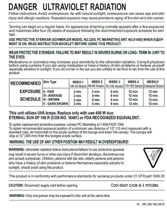
 weeks of exposure following the recommended exposure schedule for skin type.")
53 Tanning can begin on a regular basis. An appearance of tanning normally occurs after a few exposures and maximizes after four (4) weeks of exposure following the recommended exposure schedule for skin type. In order to provide for maintenance of a tan a maximum of two (2) weekly 12 minute sessions is recommended from the fifth week onward. Do not tan more than once in a 24 hour period. USE PROTECTIVE EYEWEAR, SUPER SUNNIES WHENEVER THE UNIT IS ENERGIZED. READ AND FOLLOW THE INSTRUCTION BOOKLET BEFORE USING THIS PRODUCT. To avoid electrical shock during maintence disconnect power from the unit. This product is in conformity with performance standards for sunlamp products under 21 CFR FDA. 53
54 13. uwe EQUIPMENT WARRANTY 1. WARRANTY - PC Marketing, Inc. d/b/a PC Tan (the Company ) warrants that electrical components are free from defects in its materials and workmanship, under normal use, for one year ( Warranty Period ) beginning from the purchase invoice date of the uwe indoor tanning equipment ( Product ) is purchased from the Company or an authorized Distributor of the Company or from an authorized Dealer or Representative of such Distributor or Dealer (collectively the Distributor ), if you, the original purchaser ( Purchaser ), retain ownership during the Warranty Period. This Warranty is nontransferable. THE WARRANTY CONTAINED IN THIS SECTION 1 IS SUBJECT TO VOIDANCE IN ACCORDANCE WITH SECTION WARRANTY FOR ITEMS NOT COVERED BY THE ONE YEAR WARRANTY SET FORTH IN SECTION 1; ACRYLIC SURFACES. Lamps, lamp starters, filter glass plates; metal structure, plastic covers and air filters are not covered under this warranty. THE WARRANTY CONTAINED IN THIS SECTION 2 IS SUBJECT TO VOIDANCE IN ACCORDANCE WITH SECTION VOIDANCE OF THE WARRANTY. THE WARRANTIES SET FORTH IN SECTIONS 1 AND 2 HEREIN ABOVE ARE VOID IF YOU: TRANSFER THE PRODUCT TO A THIRD PARTY, MODIFY THE PRODUCT, MISUSE THE PRODUCT, SUBJECT THE PRODUCT TO ABNORMAL CONDITIONS OF OPERATION, ATTEMPT UNAUTHORIZED REPAIRS TO THE PRODUCT, DO NOT USE ORIGINAL EQUIPMENT MANUFACTURER (OEM) REPLACEMENT PARTS, DO NOT FOLLOW THE CARE AND USE INSTRUCTION MANUAL CONCERNING SPACE, ELECTRICAL AND ENVIRONMENTAL REQUIREMENTS, SUBJECT THE PRODUCT TO ACCIDENT, MISUSE OR MISAPPLICATION; OR SERVICE THE PRODUCT BY ANYONE OTHER THAN THE COMPANY OR AN AUTHORIZED SERVICE REPRESENTATIVE OF THE COMPANY OR DISTRIBUTOR 4. WARRANTY RETURNS. All warranty claims can be handled through the Company or Distributor. If you do not know the phone number of the Distributor, you can contact the Company at FAST-TAN, Monday through Friday from 9:00 AM to 5:00 PM EST. Warranty covered items are to be returned on a part for part replacement. All freight charges are the sole responsibility of the Purchaser. 5. DISTRIBUTOR WARRANTIES. To the extent representations, warranties or commitments are extended to the Purchaser by a Distributor, such representations, warranties and commitments will be those of the Distributor alone, and will not be attributed to the Company and the Company shall not be responsible for same. 6. DISCLAIMER OF WARRANTIES. EXCEPT AS EXPRESSLY STATED IN SECTION 1 AND 2 HEREIN ABOVE, THERE ARE NO OTHER WARRANTIES BY THE COMPANY OR DISTRIBUTOR, EXPRESSED OR IMPLIED, BY OPERATION OF LAW OR OTHERWISE. THE COMPANY AND DISTRIBUTOR DISCLAIM ALL IMPLIED AND EXPRESS WARRANTIES, INCLUDING BUT NOT LIMITED TO ANY IMPLIED WARRANTY OF MERCHANTABILITY OR FITNESS FOR A PARTICULAR PURPOSE. 54
55 7. LIMITATION OF LIABILITY. THE COMPANY OR DISTRIBUTOR SHALL NOT BE LIABLE, WHETHER IN CONTRACT OR TORT, FOR ANY LOSS OR DAMAGE, INCLUDING BUT NOT LIMITED TO SPECIAL, INDIRECT, CONSEQUENTIAL, PROPERTY, ECONOMIC OR PERSONAL DAMAGES OF THE END USER, OR THIRD PARTIES, EVEN IF ADVISED OF THE POSSIBILITIES OF SUCH DAMAGES, ABOVE OR BEYOND THE REPAIR, REPLACEMENT OR REFUND OF ANY DEFECTIVE PRODUCT, WHICH SHALL BE THE PURCHASER S SOLE REMEDY. THE PURCHASE PRICE OF THE PRODUCT IS A CONSIDERATION IN LIMITING THE COMPANY S AND DISTRIBUTOR S LIABILITY. 8. LOCAL LAWS. Laws pertaining to the rights and limitations of the Warranty vary from state to state. The limitations set forth herein may not be applicable to the Purchaser, or Purchaser may have other legal rights not referenced herein. 9. MISCELLANEOUS 10. VALIDATION. To validate that you are the original purchaser of the Product from the Company or a Distributor and to ensure that you receive the above-recited benefits under the Warranty, please provide the information on the warranty card, sign the card and mail it within (30) days of purchase to: 11. SPARE AND REPLACEMENT PARTS. Original Equipment Manufacturers (OEM) lamps and replacement parts are available by direct order. To order, call FAST-TAN. Please have Credit Card information available when calling or write: GOVERNING LAW. This Warranty shall be governed by, interpreted by and enforced in accordance with the substantive and procedural laws of the State of New Jersey, and the United States of America, conflict of laws notwithstanding. This Warranty and any such claims, disputes or actions is domiciled. The Company, Distributor and Purchaser hereby agree to submit to the subject matter and personal jurisdiction and venue of said courts to resolve any disputes. If any term or provision of this Warranty is adjudicated to be invalid by any Court have jurisdiction, such provision shall be inoperable and deemed omitted and shall not invalidate the remaining provisions hereof. ENTIRE AGREEMENT. This Warranty constitutes the entire agreement of the Purchaser, the Distributor and the Company as to the subject matter and there are no other understandings, agreements or terms, whether oral or written, between the Company and the Purchaser. READ AND UNDERSTAND THIS WARRANTY. Before signing and returning this warranty, the Purchaser acknowledges that Purchaser has read and understands the terms herein, or has had the opportunity to have them read and explained to the Purchaser by an authorized representative. Warranty Department PC Tan 1040 Wilt Avenue Ridgefield, NJ

56 14. WARRANTY CARD 56

57 15. EMC information Lotus Warnings: Medical Electrical Equipment needs special precautions regarding EMC and needs to be installed and put into service according to the EMC information provided in the Accompanying Documents. Portable and Mobile RF Communications Equipment can affect Medical Electrical Equipment The use of accessories and cables other than those specified, with the exception of those sold by the manufacturer as replacement parts for internal components, may result in increased emissions or decreased immunity of the equipment or system. The Tanning device should not be used adjacent to or stacked with other equipment and that if adjacent or stacked use is necessary, the Tanning device should be observed to verify normal operation in the configuration in which it will be used Table 1: Guidelines and manufacturer's declaration Electromagnetic emissions The tanning device has been designed for use in the electromagnetic environment specified below. The device operator must ensure that it is used in such an environment. 57
58 Table 2: Guidelines and manufacturer's declaration Electromagnetic interference The Tanning device has been designed for use in the electromagnetic environment specified below. The device operator must ensure that it is used in such an environment. 58
59 Table 4: Guidelines and manufacturer's declaration Electromagnetic interference The Tanning device has been designed for use in the electromagnetic environment specified below. The device operator must ensure that it is used in such an environment. 59

60 Table 6: Recommended safe distances between portable and mobile HF communications equipment and Lotus The Tanning device has been designed for use in an electromagnetic environment in which the radiated HF interference is controlled. The operator of the device can help to reduce electromagnetic interference by maintaining a safe distance between the portable and mobile HF communication devices (transmitters) and the device itself as recommended below with regard to the communication device's maximum output power. 60

61 ID.-NR / 12/15 61
Operating Instructions. Model: idome SWING PC MARKETING 1040 WILT AVENUE RIDGEFIELD, NJ FAST TAN
 Operating Instructions Model: idome SWING PC MARKETING 1040 WILT AVENUE RIDGEFIELD, NJ 07657 1-800-FAST TAN Forward The idome is built with state-of-the-art technology and is safe to operate. However,
SunMaster Shadow. Care and Use Guide. Important! Read this manual before installing, operating or servicing this product.
 From Place Stamp Here Care and Use Guide UVA SunSystems, Inc. 6208 Technology Dr. Browns Summit, NC 27214 FOLD AT LINE AND SECURE WITH TAPE CUT ON DOTTED LINE SunMaster Shadow 32 Lamp Commercial Tanning
INDOOR TANNING EQUIPMENT CARE, USE AND INSTALLATION INSTRUCTIONS
 INDOOR TANNING EQUIPMENT CARE, USE AND INSTALLATION INSTRUCTIONS Model: CPS BLACK ENERGY BLACK ENERGY XL PC MARKETING 1040 WILT AVENUE RIDGEFIELD, NJ 0767 1-800-FAST TAN 1 Foreword Your unit is built according
User Guide. Lubricus Lubrication System LUB-D1/LUB-D2/LUB-D3/LUB-D4 (24 VDC)
") User Guide Lubricus Lubrication System LUB-D1/LUB-D2/LUB-D3/LUB-D4 (24 VDC) version 04/2013 Content General Information 3 Warning 3 Scope of Supply 3 Overview 3 General safety details 4 Intended use 4
User Guide Lubricus Lubrication System LUB-D1/LUB-D2/LUB-D3/LUB-D4 (24 VDC) version 04/2013 Content General Information 3 Warning 3 Scope of Supply 3 Overview 3 General safety details 4 Intended use 4
10 min OPERATING INSTRUCTIONS. Face Cooling EXTREME POWER TEMPTRONIC SUN SELECT 48
 EXPOSURE 10 min T I M E OPERATING INSTRUCTIONS Face Cooling SUN SELECT 48 EXTREME POWER TEMPTRONIC Operating instructions SUN SELECT 48 EXTREME POWER TEMPTRONIC 1507077-01 / us / 09.2012 Contact information
Service information. How to avoid equipment failures with preventive maintenance measures. 1. General information 08/2017
 Service information 08/2017 How to avoid equipment failures with preventive maintenance measures Product line Tower pureenergy 1.1 Definitions - Qualified, trained and authorized service technician Qualified
Product range. isolde The successful tanning lamp program for all, who appreciate the proven Philips product quality. A perfect team.
 Product range isolde The successful tanning lamp program for all, who appreciate the proven Philips product quality. A perfect team. Tanning with pleasure The intelligent isolde product line is the result
A SSEMBLY A ND U SER G UIDE
 A SSEMBLY A ND U SER G UIDE M O D E L S P R O 2 4 R S / 2 4 R S F / 2 4 R S T 2 6 R S / 2 6 R S T 21165A Lifetime Warranty What Is Covered? SunQuest warrants your tanning unit to be free of structural
WELDING INVERTER. PEGAS 160 E Smart PEGAS 200 E Smart OPERATING MANUAL. ALFA IN a.s. PEGAS E Smart Manual EN 04
 WELDING INVERTER PEGAS 160 E Smart PEGAS 200 E Smart OPERATING MANUAL PEGAS 160-200 E Smart Manual EN 04 2/12 CONTENT: 1. INTRODUCTION... 3 2. SAFETY INSTRUCTIONS AND WARNINGS... 4 3. TECHNICAL DATA...
Product range 2010 /11. isolde the new generation of Philips tanning lamps
 Product range 2010 /11 isolde the new generation of Philips tanning lamps Tanning is pure joy of life The isolde product range, the new generation of Philips tanning lamps, provides a sophisticated choice
DANGER DANGER DANGER WARNING CAUTION RECOMMENDED EXPOSURE TIMES IN MINUTES. Unpacking and Inspection
 DANGER Ultraviolet radiation. Follow instructions. Avoid overexposure. As with natural sunlight, overexposure can cause eye and skin injury and allergic reactions. Repeated exposure may cause premature
Navigator ORDERCODE 40410
 Navigator ORDERCODE 40410 Congratulations! You have bought a great, innovative product from Showtec. The Showtec Navigator brings excitement to any venue. Whether you want simple plug-&-play action or
Assembly and Maintenance Manual Type ASNU
 Assembly and Maintenance Manual Type ASNU Hatschekstr.36 69126 Heidelberg Germany Tel +49(0)6221 30470 Fax +49(0)6221 304731 info@stieber.de www.stieber.de Date of issue: 30.05.2018 GB Revision: 0 U:\EngUsers\!ProduktDoku\1AAA_Einbauerklaerung_Wartungsanleitung_Konformitaetserklaerung\1AAA_Wartungsanleitungen\Orginal_Worddatei\_ASNU.docx
WARNING: FAILURE TO FOLLOW THESE RULES MAY RESULT IN SERIOUS PERSONAL INJURY CAUTION: INSTALLATION LOCATION:
 2 Please read the safety and installation instructions carefully to help ensure a correct and SAFE installation of your Second Wind Ultraviolet Germicidal Photo-catalytic Air Purifier. WARNING: FAILURE
12 min OPERATING INSTRUCTIONS ULTRA POWER TEMPTRONIC AFFINITY 950
 EXPOSURE 12 min T I M E OPERATING INSTRUCTIONS AFFINITY 950 ULTRA POWER TEMPTRONIC Operating instructions AFFINITY 950 ULTRA POWER TEMPTRONIC 1003519-01 / us / 09.2012 Contact information Contact information
USER MANUAL A
 Pro 16SE USER MANUAL Limited Lifetime Warranty SunQuest warrants your tanning unit to be free of structural defects in its material and workmanship, under normal use, for its lifetime. SunQuest will repair
MP V 8A Electronic Smart Charger. Instruction and Information Manual
 MP7428 12V 8A Electronic Smart Charger Instruction and Information Manual In order to ensure correct and safe usage of your battery charger, you should read these instructions carefully. Please retain
INDOOR TANNING EQUIPMENT CARE, USE AND INSTALLATION INSTRUCTIONS
 INDOOR TANNING EQUIPMENT CARE, USE AND INSTALLATION INSTRUCTIONS Model: SunBoard XTT PC MARKETING 1040 WILT AVENUE RIDGEFIELD, NJ 07657 1-800-FAST TAN 1 Preface Your unit has been built in accordance with
DANGER DANGER DANGER WARNING CAUTION RECOMMENDED EXPOSURE TIMES IN MINUTES. Electrical Requirements. Unpacking and Inspection
 DANGER Ultraviolet radiation. Follow instructions. Avoid overexposure. As with natural sunlight, overexposure can cause eye and skin injury and allergic reactions. Repeated exposure may cause premature
Assembly and Maintenance Manual Type AS
 Assembly and Maintenance Manual Type AS Hatschekstr.36 69126 Heidelberg Germany Tel +49(0)6221 30470 Fax +49(0)6221 304731 info@stieber.de www.stieber.de Date of issue: 30.05.2018 GB Revision: 0 U:\EngUsers\!ProduktDoku\1AAA_Einbauerklaerung_Wartungsanleitung_Konformitaetserklaerung\1AAA_Wartungsanleitungen\Orginal_Worddatei\_AS.docx
 IU0U automatic charger Read these instructions carefully before the installation and commissioning and keep them in a safe place. Pass it on to the buyer in case of the further sale of the system. Contents
C3 Operating Instructions
 Version 3.1 Stand 09.2014 Robert Bosch (Australia) Pty. Ltd. 1555 Centre Road Clayton, Victoria 3168 C3 Operating Instructions For further information please contact Bosch at: Australia 1300 30 70 40 www.boschautoparts.com.au
OPERATING INSTRUCTIONS
 1505772 XXL-110 BLUEBERRY BLUES Dynamic Power E E S X PO U R 10 min TIME OPERATING INSTRUCTIONS Face Cooling Soltron, a Division of JK-Products & Services, Inc. 1 Walter Kratz Drive Jonesboro, AR 72401
SI AT A22. English. Printed: Doc-Nr: PUB / / 000 / 01
 SI AT A22 English 1 Information about the documentation 1.1 About this documentation Read this documentation before initial operation or use. This is a prerequisite for safe, trouble-free handling and
Exchange of rollers from the XTS-Mover
 Service documentation for AT901-0050-0550 and AT9011-00x0-0550 Version: Date: 1.0 0.10.017 Table of contents Table of contents 1 Foreword... 5 1.1 Notes on the documentation... 5 1. Documentation issue
5 IN 1 JUMP START OPERATION & MAINTENANCE INSTRUCTIONS MODEL NO: JS5IN1 PART NO: LS0810
 5 IN 1 JUMP START MODEL NO: JS5IN1 PART NO: 6240005 OPERATION & MAINTENANCE INSTRUCTIONS LS0810 INTRODUCTION Thank you for purchasing this CLARKE product. Before attempting to use this product, please
OPERATING INSTRUCTIONS
 1507090 E E S X PO U R 20 min TIME OPERATING INSTRUCTIONS Face Cooling SUN ANGEL DUO S 52 SUN ANGEL DUO J K - P ro d u c t s & S e r v i ce s, I n c. 1 Walter Kratz Drive Jonesboro, AR 72401 Phone: 800.643.0086
(42001) Neck Massager / Masseur de cou User Manual / Manuel de l utilisateur
 Neck Massager / Masseur de cou User Manual / Manuel de l utilisateur") (42001) Neck Massager / Masseur de cou User Manual / Manuel de l utilisateur IMPORTANT SAFETY INSTRUCTIONS PLEASE READ BEFORE OPERATION WARNING: To reduce the risk of burns, fire, electric shock or injury
(42001) Neck Massager / Masseur de cou User Manual / Manuel de l utilisateur IMPORTANT SAFETY INSTRUCTIONS PLEASE READ BEFORE OPERATION WARNING: To reduce the risk of burns, fire, electric shock or injury
SI AT A22. English. Printed: Doc-Nr: PUB / / 000 / 03
 SI AT A22 English 1 Information about the documentation 1.1 About this documentation Read this documentation before initial operation or use. This is a prerequisite for safe, trouble-free handling and
Mod: KLD6-12/35XLAS-N
 12/2011 Mod: KLD6-12/35XLAS-N Production code: 1914070 INSTRUCTION MANUAL LOGIC LINE PLUS HOOD Reseller Stamp for Warranty Dear customer, Above all, thank you for choosing our product and we would like
KeContact P20. User manual
 KeContact P20 User manual Comments to this manual In this manual you will find warnings against possible dangerous situations. The used symbols apply to the following meanings:!! WARNING! Indicates a potentially
Multi-Mover Charger for model L25
 Multi-Mover Charger for model L25 Important safety instruction. Keep these instructions. This manual contains important instructions for the safety of the user and the operation of the device. 1. SYMBOLS
OPERATING INSTRUCTIONS ERGOLINE AFFINITY
 OPERATING INSTRUCTIONS ERGOLINE AFFINITY Ergoline AFFINITY 1000516-00- / us / 09.2006 OPERATING INSTRUCTIONS AFFINITY 500 Turbo Power AFFINITY 600 Turbo Power Air Condition AFFINITY 800 Turbo Power Temptronic
DIGITAL TEMPERATURE CONTROL
 Fridge / Freezer / Warmer with DIGITAL TEMPERATURE CONTROL MODEL MHD13F-DM SPECIFICATION DESIGNATION OF PARTS MODEL CAPACITY OUTER DIMENSIONS INPUT RATING ( or FREEZER) (WARMER) REFRIGERANT WEIGHT MHD13F-DM
OPERATIONS MANUAL CR Thermoreactor
 OPERATIONS MANUAL CR 2200 Thermoreactor CR 2200 Note For the most recent version of the manual, please visit www.ysi.com. Contact Copyright YSI 1725 Brannum Lane Yellow Springs, OH 45387 USA Tel: +1 937-767-7241
HIGH FREQUENCY AUTOMATIC BATTERY CHARGER
 HIGH FREQUENCY AUTOMATIC BATTERY CHARGER MODEL NO: HFBC12 PART NO: 6267000 OPERATION & MAINTENANCE INSTRUCTIONS LS0814 INTRODUCTION Thank you for purchasing this CLARKE High Frequency Automatic Battery
Instructions for Fitting, Operating and Maintenance Canopy Door RE / (St.: )
") EN Instructions for Fitting, Operating and Maintenance Canopy Door 1 818 012 RE / (St.: 12.2010) 12.2010 ENGLISH Contents 1 Safety Instructions... 3 1.1 Qualified persons... 3 1.2 Symbols and signal words
EN Instructions for Fitting, Operating and Maintenance Canopy Door 1 818 012 RE / (St.: 12.2010) 12.2010 ENGLISH Contents 1 Safety Instructions... 3 1.1 Qualified persons... 3 1.2 Symbols and signal words
OPERATING INSTRUCTIONS
 EXPOSURE 20 min T I M E OPERATING INSTRUCTIONS SUN ANGEL DUO 600 Operating instructions SUN ANGEL DUO 600 INDIVUDUAL PERFORMANCE 1014226-00 / us / 08.2013 Notice: You do not need to become tan for your
DANGER. Electrical Requirements. Hardware Inventory (These items and a small pillow) DANGER WARNING CAUTION
 DANGER WARNING CAUTION") Ultraviolet radiation. Follow instructions. Avoid overexposure. As with DANGERnatural sunlight, overexposure can cause eye and skin injury and allergic reactions. Repeated exposure may cause premature
Ultraviolet radiation. Follow instructions. Avoid overexposure. As with DANGERnatural sunlight, overexposure can cause eye and skin injury and allergic reactions. Repeated exposure may cause premature
RF6 / RF10 / RF18 Installation Instructions
 RF6 / RF10 / RF18 Installation Instructions Thank you very much for purchasing PIAA product. Read this instruction manual thoroughly for proper use of the product. After completing your installation, please
Operating instructions Bedienungsanleitung Mode d emploi
 HMI F1600 800.1600 Operating instructions Bedienungsanleitung Mode d emploi Urs Recher / model: Deborah Frey, Germany OPERATING INSTRUCTIONS BRONCOLOR HMI F1600 HMI 800.1600 Before use Please read all
Digital Apex Locator. ipex OPERATION MANUAL OM-E0285E
 Digital Apex Locator ipex OPERATION MANUAL 0197 OM-E0285E The EU directive 93/42/EEC was applied in the design and production of this medical device. Thank you for purchasing the ipex. This is apex locator.
OPERATING INSTRUCTIONS
 SUNANGEL S 46 OPERATING INSTRUCTIONS EXPOSURE 20 min TIME OPERATING INSTRUCTIONS 1006840-00 / us / kn / 11.2008 SUNANGEL S 46 Identify your tanning device For contact with Customer Services, please write
UV-AIRE AIR PURIFYING SYSTEM
 UV-AIRE AIR PURIFYING SYSTEM Model: UV-16/24 The UV-Aire unit is designed to emit powerful UVC Band light rays, which sterilize and reduce airborne microorganisms as they pass through a heating or air
Q-Series Ultraviolet Lamps OPERATOR S MANUAL
 Q-Series Ultraviolet Lamps OPERATOR S MANUAL AM05008-3 PRINTED IN U.S.A. ISSUED: FEBRUARY 2011 Q-Series Ultraviolet Lamps DANGER Ultraviolet radiation emitted from this product. Avoid exposure. ALWAYS
Specifications THIS UNIT UTILIZES UVA LAMPS. REPLACE ONLY WITH PHILIPS PROFESSIONAL 160W AND JK ERGOLINE 500 SE C11292 (FACE TANNER).
.") Specifications 450 Length: 92 Width: 46.5 Height: 45 Shipping Weight: 1000 Lbs. No. of Lamps: 46 (42-160 Watt, 4-400 Watt) Electrical: 28 AMPS @ 240 Volts 3Ø Circuit Required: 120/240V 3Ø 40 Amp 3-Pole
Specifications 450 Length: 92 Width: 46.5 Height: 45 Shipping Weight: 1000 Lbs. No. of Lamps: 46 (42-160 Watt, 4-400 Watt) Electrical: 28 AMPS @ 240 Volts 3Ø Circuit Required: 120/240V 3Ø 40 Amp 3-Pole
Cordless Rechargeable Saw Instructions for Use
 Technical data Voltage: DC 10.8V Weight: 1.25Kg Stroke rate: 0-2100/min Stroke: 15mm Cutting capacity: max diameter in wood 80mm / in soft metal 7mm Charging time: Between 5.0-5.5 Hours Battery: 1.3Ah
PLEASE READ THESE INSTRUCTIONS BEFORE USE
 Your Partner in Pain Management PLEASE READ THESE INSTRUCTIONS BEFORE USE NOTE: Your Oska Pulse was fully charged before shipping and should be ready for immediate use. Relief can vary depending on the
Register your instrument! HeatSealer S100. Operating manual
 00N) manual Register your instrument! www.eppendorf.com/myeppendorf Operating manual Copyright 2015 Eppendorf AG, Germany. All rights reserved, including graphics and images. No part of this publication
USER MANUAL MPS 1-5KW SERIES
 USER MANUAL MPS 1-5KW SERIES Low Series Frequency Solar and Wind Power Charging Inverter CONTENTS 1 WWW.NEXTGENNRG.COM 1. Introduction... 3 2. Profile Structure 4 2.1. Working Principle 4 2.2.Product Features..5
User s Manual. Automatic Switch-Mode Battery Charger
 User s Manual Automatic Switch-Mode Battery Charger IMPORTANT Read, understand, and follow these safety rules and operating instructions before using this battery charger. Only authorized and trained service
OPERATION & MAINTENANCE INSTRUCTIONS
 AUTOMATIC BATTERY CHARGER / MAINTAINER MODEL NO: CBO9-6/12 PART NO: 6267020 OPERATION & MAINTENANCE INSTRUCTIONS LS0615 INTRODUCTION Thank you for purchasing this CLARKE product. Before attempting to use
MOVING HEAD. User manual CAUTION!
 TM MOVING HEAD OBY-3 User manual CAUTION! contents Features Description of the appearance Inspection. Safety instructions Lamp Installation Rigging Connection with the mains Linking Instruction for gobo
User Manual Saturn Revised September 21, 2004
 User Manual Saturn Revised September 21, 2004 INDEX SECTION PAGE 1.0 INTRODUCTION 3 2.0 SAFETY WARNINGS 3 2.1 Photosensitivity know the symptoms 3.0 FEDERAL REGULATIONS 4 3.1 Guidelines for the Salon Owner
Model: UV-16R/24 READ THESE INSTRUCTIONS CAREFULLY AND COMPLETELY BEFORE PROCEEDING WITH THE INSTALLATION.
 U V - AIRE AIR PURIFYING S YSTEM Model: UV-16R/24 ITEMS INCLUDED IN KIT: 1-24Volt UV-Aire Ballast Assembly 1-Mounting Base 1-Ultraviolet Lamp 6-Sheet Metal Mounting Screws 1-Instruction Sheet 1-Fiberglass
c-go 24V/6A 24V/8A 24V/12A
 c-go 24V/6A 24V/8A 24V/12A Battery charger GB Instruction manual 1 Index 1. Product description... 2 2. Safety advices... 3 3. Quick start guide... 4 4. Operation... 4 5. Problem solving... 6 6. Specifications...
Inazuma Installation and Operating Instructions INAZUMA HD PRO UV-C. High-Performence Duo UVC Lamp
 Inazuma Installation and Operating Instructions INAZUMA HD PRO 50.000 UV-C High-Performence Duo UVC Lamp Edelstahl-Trommelfilter & High-End-Teichzubehör Index page 1. General Information... 3 1.1. Introduction...
DANGER. Unpacking and Inspection. Hardware Inventory (These items and a small pillow) Electrical Requirements DANGER WARNING CAUTION
 Electrical Requirements DANGER WARNING CAUTION") Ultraviolet radiation. Follow instructions. Avoid overexposure. As with DANGERnatural sunlight, overexposure can cause eye and skin injury and allergic reactions. Repeated exposure may cause premature
Ultraviolet radiation. Follow instructions. Avoid overexposure. As with DANGERnatural sunlight, overexposure can cause eye and skin injury and allergic reactions. Repeated exposure may cause premature
Safety, Installation and Service Manual Models 1952, 1953 & 1972
 Ultraviolet Germicidal Lamps Model 1952 24 Rooftop Unit Model 1953 32 Rooftop Unit Model 1972 Rooftop Unit, Internal Mount Safety, Installation and Service Manual Models 1952, 1953 & 1972 READ AND SAVE
OPERATION & MAINTENANCE INSTRUCTIONS
 AUTOMATIC BATTERY CHARGER / MAINTAINER MODEL NO: CBO9-12 PART NO: 6267025 OPERATION & MAINTENANCE INSTRUCTIONS LS0315 INTRODUCTION Thank you for purchasing this CLARKE product. Before attempting to use
OPERATION & MAINTENANCE INSTRUCTIONS
 AUTOMATIC BATTERY CHARGER / MAINTAINER MODEL NO: CBO9-12 PART NO: 6267025 OPERATION & MAINTENANCE INSTRUCTIONS ORIGINAL INSTRUCTIONS LS0118 - ISS 3 INTRODUCTION Thank you for purchasing this CLARKE product.
Stereo Power Amplifier
 4-569-998-12(1) Stereo Power Amplifier Operating Instructions GB For customers in the United States: The warranty for this product is included in this manual (page 12). Owner s Record The model and serial
MODELS PRO 28LX / 28LXT / 28LX2F USER GUIDE
 MODELS PRO 28LX / 28LXT / 28LX2F USER GUIDE Limited Lifetime Warranty SUNVISION warrants your tanning unit to be free of structural defects in its material and workmanship, under normal use, for its lifetime.
100 Watt Power Inverter + USB INSTRUCTION MANUAL HT8710-AUOXY
 100 Watt Power Inverter + USB INSTRUCTION MANUAL HT8710-AUOXY CONTENTS Warranty 2 Introduction 3 Environmental protection 3 Specifications 3 General safety warnings and instructions 4 Know your product
Slimax LED Curing Light System
 Slimax LED Curing Light System Operators Manual Beyes Dental Canada Inc 1 TABLE OF CONTENTS SAFETY PRECAUTIONS ASSEMBLY BATTERY MODES EXPOSURE TIME ACTIVATING AND DEACTIVATING THE LIGHT BOOST AND REGULAR
Caddy. Tig 2200i AC/DC. Instruction manual GB Valid for: serial no. 711-, 747-xxx-xxxx
 Caddy Tig 2200i AC/DC Instruction manual 0460 225 301 GB 20180920 Valid for: serial no. 711-, 747-xxx-xxxx TABLE OF CONTENTS 1 SAFETY... 4 1.1 Meaning of symbols... 4 1.2 Safety precautions... 4 2 INTRODUCTION...
GARDENA. N FIN P E I DK S NL F GB D
 GARDENA AccuCut 400 Li Art. 8840 D Betriebsanleitung Operating Instructions F Mode d emploi Coupe bordures NL Instructies voor gebruik S Bruksanvisning freeetrim DK Brugsanvisning freeetrim I Istruzioni
VARIFUEL MAINTENANCE AND REPAIR INSTRUCTIONS
 VARIFUEL2 140-65 MAINTENANCE AND REPAIR INSTRUCTIONS MOTORTECH Gas Regulation P/N 01.50.008-140-65-EN Rev. 06/2015 Copyright Copyright 2015 MOTORTECH GmbH. All rights reserved. Distribution and reproduction
Model: SPTOGT01 TRACTOR PTO GENERATOR
 www.scintex.com.au sales@scintex.com.au Model: SPTOGT01 TRACTOR PTO GENERATOR SET UP, OPERATING, AND SERVICING INSTRUCTIONS Read this material before using this product. Failure to do so can result in
900 PEAK AMP PORTABLE JUMP STARTER
 900 PEAK AMP PORTABLE JUMP STARTER Item Number W1665 OWNER S MANUAL WARNING It is the owner and/or operators responsibility to study all WARNINGS, operating, and maintenance instructions contained on the
Soothes every aching muscle in its path.
 Soothes every aching muscle in its path. MAX 2 Dual-Node Massager Powerful massage. Maximum relief. Merrimack, New Hampshire USA 03054 800-846-3000 Brookstone.com Table of contents Warnings and Cautions....................................................
User s Manual Power Supply. IM E 2nd Edition. Yokogawa Electric Corporation
 User s Manual 701934 Power Supply Yokogawa Electric Corporation 2nd Edition Foreword Revisions Thank you for purchasing the 701934 Power Supply. This user's manual contains useful information about the
Podiatry Procedures Chair. For Models: Barrier-Free. User s Guide
 Podiatry Procedures Chair For Models: 646 647 Barrier-Free User s Guide Product Information (The information below is required when calling for service.) Dealer : Date of Purchase: Model / Serial Number:
Pro Booster 802Li. Please read and fully understand the instructions in this manual before operation. Keep this manual safe for future reference.
 Please dispose of packaging for the product in a responsible manner. It is suitable for recycling. Help to protect the environment, take the packaging to the local amenity tip and place into the appropriate
Operating instructions ErgoPack 600 E
 Operating instructions ErgoPack 600 E Operation of the device is only permitted if the operating instructions have been carefully read and understood before use! Declaration of conformity EU declaration
IMPORTANT SAFETY INSTRUCTIONS VP200ESK SAFETY INSTRUCTIONS 1
 IMPORTANT SAFETY INSTRUCTIONS VP200ESK SAFETY INSTRUCTIONS VP200ESK SAFETY INSTRUCTIONS 2 MAIN COMPONENTS ITEMS INCLUDED SPRAYER TANK 6.8 VOLT BATTERY -3400 mah 6.8 VOLT CHARGER NOZZLE WRENCH TANK CAP
Wilo-Control SC-Fire Jockey
 Pioneering for You Wilo-Control SC-Fire Jockey de en fr Einbau- und Betriebsanleitung Installation and operating instructions Notice de montage et de mise en service nl Inbouw- en bedieningsvoorschriften
SPACE SAVING FOLDING TREADMILL SF-T7632 USER MANUAL
 SPACE SAVING FOLDING TREADMILL SF-T7632 USER MANUAL IMPORTANT: Read all instructions carefully before using this product. Retain owner s manual for future reference. For customer service, please contact:
6 Bay Battery Charger Operation Manual
 6 Bay Battery Charger Operation Manual Sunoptic Technologies 6018 Bowdendale Avenue Jacksonville, FL 32216 USA Customer Service: 904 737 7611 Toll Free 877 677 2832 EC REP RMS UK, Ltd. 28 Trinity Road
rechargeable umbrella light
 rechargeable umbrella light Model 98154 assembly And Operation Instructions Diagrams within this manual may not be drawn proportionally. Due to continuing improvements, actual product may differ slightly
Instruction Manual. Blink HQ Charger. Charge on. a CarCharging Company
 Instruction Manual Blink HQ Charger a CarCharging Company 2014 by Blink Network, LLC No part of the contents of this document may be reproduced or transmitted in any form or by any means without the express
JUMPSTART MODEL NO: JS1000, JS1010 & JS1224 OPERATING & MAINTENANCE INSTRUCTIONS PART NO: , & GC0514
 JUMPSTART MODEL NO: JS1000, JS1010 & JS1224 PART NO: 6240040, 6240035 & 6240045 OPERATING & MAINTENANCE INSTRUCTIONS GC0514 INTRODUCTION Thank you for purchasing this CLARKE Jumpstart. Before attempting
1.Safe testing IMPORTANT:
 Electricity is dangerous and can cause injury and death. Always treat it with the greatest of respect and care. If you are not quite sure how to proceed, then stop, take advice from a qualified person.
VARIFUEL MAINTENANCE AND REPAIR INSTRUCTIONS
 VARIFUEL2 200-120 MAINTENANCE AND REPAIR INSTRUCTIONS MOTORTECH Gas Regulation P/N 01.50.008-200-120-EN Rev. 06/2015 Copyright Copyright 2015 MOTORTECH GmbH. All rights reserved. Distribution and reproduction
Operator's Manual. Storage System. Ultrasound Probe Cabinet. Manufactured by:
 Storage System Ultrasound Probe Cabinet Operator's Manual Manufactured by: CIVCO Medical Solutions 102 First Street South Kalona, IA 52247 USA 319.248.6757 / 800.445.6741 WWW.CIVCO.COM Copyright 2018 All
DANGER DANGER DANGER WARNING CAUTION RECOMMENDED EXPOSURE TIMES IN MINUTES. Unpacking and Inspection
 DANGER Ultraviolet radiation. Follow instructions. Avoid overexposure. As with natural sunlight, overexposure can cause eye and skin injury and allergic reactions. Repeated exposure may cause premature
Mini Aquatic ORDERCODE 30844
 Mini Aquatic ORDERCODE 30844 Congratulations! You have bought a great, innovative product from Showtec. The Showtec Mini Aquatic brings excitement to any venue. Whether you want simple plug-&-play action
DANGER DANGER DANGER WARNING CAUTION RECOMMENDED EXPOSURE TIMES IN MINUTES. Electrical Requirements
 DANGER Ultraviolet radiation. Follow instructions. Avoid overexposure. As with natural sunlight, overexposure can cause eye and skin injury and allergic reactions. Repeated exposure may cause premature
Instruction Manual for Safety and Comfort
 GMH500160110 *GMH500160110* Instruction Manual for Safety and Comfort All of the Safety Instructions contained in this Manual must be read carefully and must be fully understood before you attempt to use
MULTIVOLTAGE PORTABLE BATTERY CHARGER MVM
 _ M MULTIVOLTAGE PORTABLE BATTERY CHARGER MVM User's MANUAL Code: MVM Version: 01-BF Date: OCT 2005 Page 1/10 _ 1. INTRODUCTION Before starting to use your Energic plus MVM battery charger, please take
ACCUSENSE CHARGE SERIES ON/OFF BOARD FULLY AUTOMATIC BATTERY CHARGER
 ACCUSENSE CHARGE SERIES ON/OFF BOARD FULLY AUTOMATIC BATTERY CHARGER SPECIFICATIONS: *Photo for reference only* Part number 8890439 Mode Select: Selects Battery Type Refer to Section 6. IMPORTANT: READ
CORDLESS TACKER MODEL NO: CCT48 OPERATION & MAINTENANCE INSTRUCTIONS PART NO: LS0414
 CORDLESS TACKER MODEL NO: CCT48 PART NO: 6485070 OPERATION & MAINTENANCE INSTRUCTIONS LS0414 INTRODUCTION Thank you for purchasing this CLARKE product. Before attempting to use this product, please read
Manual. Curtis Model 1625 Battery Charger. Curtis Instruments, Inc. 200 Kisco Avenue Mt. Kisco, NY
 Manual Curtis Model 1625 Battery Charger Curtis Instruments, Inc. 200 Kisco Avenue Mt. Kisco, NY 10549 www.curtisinstruments.com Read Instructions Carefully! Specifications are subject to change without
Wireless doorbell transmitter FS20 TK
 OPERATING INSTRUCTIONS Version 12/06 Wireless doorbell transmitter FS20 TK Item No. 62 03 38 Table of contents Page 1. Introduction... 3 2. Prescribed use... 4 3. Scope of delivery... 4 4. Explanation
Product Data Sheet : LIGHTHAWK 6 CELL
 Specifications Power Source: Lithium-Ion, 6600mAH, 7.8V Lamp: XPR12, PN 20356 Lamp Life: 100 hrs Light Output: 264 lumens Burn Time: up to 4 hrs. 4.5 Hour Charging Time Weight: 2.1 lbs Unit Dimensions:
Operating Manual. Follow all safety precautions!
 Operating Manual This manual contains important information necessary for the safe and efficient operation of the PhotoFluor LM-75 light source. Please read the manual in its entirety and heed all safety
ECSS. Electric Chain Saw Chain Sharpener Assembly & Operating Instructions
 ECSS Electric Chain Saw Chain Sharpener Assembly & Operating Instructions READ ALL INSTRUCTIONS AND WARNINGS BEFORE USING THIS PRODUCT. SAVE THESE INSTRUCTIONS FOR FUTURE REFERENCE. This manual provides
LED Twister II. User manual UK Version 1.0
 LED Twister II User manual 152.624UK Version 1.0 LED DUOPLEX: For indoor use only CAUTION! Please read this manual carefully before operating! Pay special attention to Sections 3 & 5 of this document.
1. INTRODUCTION SYSTEM DESCRIPTION Front Panel CONNECTION AND OPERATION TROUBLESHOOTING...8
 Contents : 1. INTRODUCTION...1 2. IMPORTANT SAFETY INSTRUCTIONS...2 3. SYSTEM DESCRIPTION...4 3.1 Front Panel...4 4. CONNECTION AND OPERATION...6 5. TROUBLESHOOTING...8 6. MAINTENANCE...9 6.1 Operation...9
V1.0. Showven Technologies Co.,Ltd.
 V1.0 Showven Technologies Co.,Ltd. SONICBOOM TM SMOKEJET USER MANUAL Foreword Thanks for choosing SHOWVEN SONICBOOM TM SMOKEJET. Please read following manual carefully and completely before operating this