slotcar racing controller FAQ / Technical Info Version 1.5 How do I connect the ACD pro to an unknown track?
|
|
|
- Penelope Knight
- 6 years ago
- Views:
Transcription
1 How do I connect the ACD pro to an unknown track? As a standard you will find two types of track polarity. The positive and the negative polarity. A positive track polarity means that the plus pole is controlled by the speed controller. A negative track polarity means that the negative pole is controlled by the speed controller. The ACD pro is working for positive tracks by default. The cable and connector colors are based on the German standard. You can use the ACD pro also for negative Track. To do this you just switch the polarity switch and reconnect the controller for negative polarity. Please see the User Manual for details. If you are not sure about the polarity and connection please follow the flowing step by step instruction to find the correct connection to every track polarity and every track colors Step (1) Remove every car from the track, remove every other controller from track and switch the track power on. Step (2) With a voltmeter search for the connector positions, between them you can measure the voltage of the track. Step (3) Please mark the found plus and minus poles. This is very important to avoid any mistakes in the Future. Step (4) Connect the ACD pro black and red wires to the marked positions. The red connector of the ACD pro goes to the plus pole. The black connector of the ACD pro goes to the minus pole. The yellow connector of the ACD pro must remain unconnected. The green LED on the ACD pro should go on. If not control the fuse on the ACD pro. Step (5) Put a car on the track. Connect the yellow wire of the ACD pro to the remaining connector of the track. You will get one of two possible situations: Situation (1) The car does nothing until you use the ACD pro. You must get the normal operation and you have found the correct connection. Situation (2) The car will start with full speed without triggering the ACD pro. So disconnect the ACD pro, switch the polarity switch to the opposite position and reconnect the ACD pro according to the found and marked positions. After that, you will be able to control the car with the ACD pro. (The polarity switch is the switch near the green and red LEDs)
2 Very Important: Please mark the connectors very clearly to avoid any mistakes in the future. Colors of the connectors The ACD pro has by default the German cable colors. The ACD pro works by default for positive wiring. To convert the connector colors to the US colors use the following table (Positive wiring): ACD pro Red Yellow Black US color White Black Red Fuses and maximum current The ACD Pro5 has 2 Fuses. The Supply fuse is 5A and the motor fuse is 7.5A The ACD Pro10 has also 2 fuses. The supply fuse is 10A and the motor fuse is 15A. The ACD Pro3 has internal fuses. The maximum pulse current is 8A. Please do not exceed this current. The ACD Pro3 is allowed to be used with Power supplies up to 10A maximum current. This is because the internal fuses are designed only for scale racing with the typical Power supplies from 1 to 10A. The operation of the ACD Pro5 and ACD Pro10 with strong power supplies is not restricted.

3 Restriction for the power supply? In general any power supply should be sufficient to work with the ACD pro. Due to the braking feature of the ACD pro some power supply will not work properly. In such cases you need to add a condenser and a resistance to your power supply. To ensure the proper working of the power supply please measure the voltage at the braking moment. If you found a voltage pulse of more than 3V as your power setting then you should make one of the followings: 1) Use a condenser of 22000µF/35V in parallel to a 180 Ohm/11W resistance. This combination must be connected to the plus and minus connectors of the power supply. Please watch the correct polarity of the condenser! 2) Connect a condenser of 10000µF/35V in parallel to a 100 Ohm/11W resistance. This combination is also good but produces little more heat. 3) If you have a regulated power supply with a current of 5A or more, so you can connect only a resistance of around 82 Ohm/11W without a condenser to the plus and minus connectors of your power supply. This is the cheapest way. Please note, that the resistance in general will produce some heat. You should mount the resistance to a metallic surface for cooling. In general the use of a condenser/resistance combination will improve the total behavior of the power supply. Sample Parts for upgrading The metal bracket maybe done using any metal strip


4 connection of the Resistance Mounting of the resistance on the heat sink of the power supply


5 Connection of the condenser if needed Please pay attention to connect the + pole of the condenser to the + pole of the power supply Power adapter If you don t wish to add any parts to your power supply you can buy a special adapter. This adapter may be connected directly to the power supply by standard connectors. Price and delivery time on request. Photo of the external adapter for direct connection to a any power supply


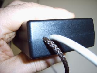
6 Do I need to protect the cables? Yes, Even if the cables of the ACD pro are very reliable they can not withstand too much pull force. The cables are sufficient for all normal racing situations. The gray cable of the ACD Pro5 / Pro10 is light. In some cases you need a Pull strength to avoid stresses of the cable. Since this is not often necessary so we don t deliver this Pull strength with the standard controller. You can mount this pull strength by your self using a plastic cord. You need a 3 mm plastic cord with the length of 105 cm. Make a small 3mm hole in the Black Box using a cutter. (!! Pay attention to not damage any Electronic Parts within the box) Make a knot at one end of the cord and a double knot on the other end Please see the following Photos for the mounting details:


7


8


9 What is the function of the Knops and switches? The red knob is for the brake adjustment The gray knob is for adjusting the start speed of the slot car (Sensitivity) The black small knob adjusts the maximum speed of the slot car In addition to these knobs you have the trigger characteristic switch. This switch changes the trigger behavior from Aggressive to smooth. The factory default setting: Slider to the upper Position = aggressive

10 Polarity switch. The factory Default position is positive.(slider set to the LEDs) Attention: This switch must be set ones for a given Track. If you switch it by mistake then the car maybe go to full speed. Please see the connection procedure in this FAQ and read the manual. LEDs The green LED illuminates constantly as soon as the power is connected. The red LED is normally off. This LED will flash if the controller detects a malfunction.
Electronic Dynamo Regulator INSTRUCTION MANUAL. COPYRIGHT 2014 CLOVER SYSTEMS All Rights Reserved
 DRM TM DRM-HP TM Electronic Dynamo Regulator INSTRUCTION MANUAL COPYRIGHT 2014 CLOVER SYSTEMS All Rights Reserved INTRODUCTION The Clover Systems DRM is a state-of-the art all-electronic voltage and current
Welcome to PTI--Photon Technology International--Optical Building Blocks!
 Search: GO Power Supplies Model LPS-220 Lamp Power Supply OPERATION MANUAL CONTENTS 1. DESCRIPTION Introduction Specifications 2. INSTALLATION Arc Lamps Tungsten-Halogen Lamps 3. OPERATION Arc Lamps Tungsten-Halogen
Power Controller. (see note 1) 10 sec
 10 sec") Power Controller Single-phase Models EUN Series AC Power Controller with Phase-control System Allows Precise Temperature Control Models with Base-up and Soft-start Functions Available EH Series Phase Control
Power Controller Single-phase Models EUN Series AC Power Controller with Phase-control System Allows Precise Temperature Control Models with Base-up and Soft-start Functions Available EH Series Phase Control
INSTRUCTION MANUAL. BatteryMINDer. Model SCC515 Maintenance Charger- Solar Controller for use with 5 Watt and 15 Watt Solar Panels
 INSTRUCTION MANUAL Model Maintenance Charger- Solar Controller for use with 5 Watt and 15 Watt Solar Panels OVERVIEW... 2 MOUNTING INSTRUCTIONS... 3 BATTERY CONDITION INDICATOR (BCI)... 5 TESTING BATTERY...
Model Number Structure. Power Controllers G3PX. Single-phase Models. Model Number Legend
 Power Controllers GPX Refer to Safety Precautions (page 0). Single-phase Models EUN Series AC Power Controllers with Phase-control System Allow Precise Temperature Control Models with Base-up and Soft-start
Experiment 3: Ohm s Law; Electric Power. Don t take circuits apart until the instructor says you don't need to double-check anything.
 Experiment 3: Ohm s Law; Electric Power. How to use the digital meters: You have already used these for DC volts; turn the dial to "DCA" instead to get DC amps. If the meter has more than two connectors,
3/6/16 Tetrix first build robot instructions J. La Favre
 Figure 1 mount for Omni wheels - make two of these Figure 2 mount for Omni wheels, add bushing and tighten set screw of axle collar set screw should be tightened down on flat part of axle 1 Figure 3 Insert
Pre-lab Quiz/PHYS 224 Ohm s Law and Resistivity. Your name Lab section
 Pre-lab Quiz/PHYS 224 Ohm s Law and Resistivity Your name Lab section 1. What do you investigate in this lab? 2. When 1.0-A electric current flows through a piece of cylindrical copper wire, the voltage
LAB 7. SERIES AND PARALLEL RESISTORS
 Name: LAB 7. SERIES AND PARALLEL RESISTORS Problem How do you measure resistance, voltage, and current in a resistor? How are these quantities related? What is the difference between a series circuit and
SCA-80(Q) C11 REPLACEMENT ASSEMBLY MANUAL
 C11 REPLACEMENT ASSEMBLY MANUAL") SCA-80(Q) C11 REPLACEMENT ASSEMBLY MANUAL 2014-2016 AkitikA, LLC All rights reserved Revision 1p05 July 3, 2016 Page 1 of 15 Table of Contents Table of Contents... 2 Table of Figures... 2 Section 1: About
SCA-80(Q) C11 REPLACEMENT ASSEMBLY MANUAL 2014-2016 AkitikA, LLC All rights reserved Revision 1p05 July 3, 2016 Page 1 of 15 Table of Contents Table of Contents... 2 Table of Figures... 2 Section 1: About
Vehicle Security System
 Installation Instructions Vehicle Security System PROFESSIONAL INSTALLATION STRONGLY RECOMMENDED Installation Precautions: Roll down window to avoid locking keys in vehicle during installation Avoid mounting
ECT Display Driver Installation for AP2 Module
 ECT Display Driver Installation for AP2 Module Overview The ECT Display Driver is a small module with a removable wire harness that mounts behind the driver's foot well cover. All wiring connections are
VS 315 DELUXE 4-CHANNEL MOTORCYCLE ALARM. Installation And Operation Manual MEGATRONIX CALIFORNIA, U.S.A. VS 315 1
 VS 315 DELUXE 4-CHANNEL MOTORCYCLE ALARM Installation And Operation Manual MEGATRONIX CALIFORNIA, U.S.A. VS 315 1 VS 315 2 INSTALLATION We recommend insulating all your soldered or crimped connections
LeafBox manual, v How to set the LeafBox?
 LeafBox manual, v1.0 LeafBox should be installed to accelerator pedal plug of Nissan Leaf. It does not matter generation or year of production, but there are various settings depend on your driving mood,
INSTALLATION GUIDE Table of Contents
 CT-3100 Automatic transmission remote engine starter systems. What s included..2 INSTALLATION GUIDE Table of Contents Door lock toggle mode..... 4 Notice...2 Installation points to remember. 2 Features..2
VECTRIX VX-2 SERVICE MANUAL. Version 1.0/May 2011 VECTRIX, LLC
 www.vectrix.com CONTENTS SECTION A: Tools 1 Tools Needed SECTION B: Mechanical Parts 1 Front Fairing 2 Front Console Cover 3 Speedometer Cover 4 Front Vertical Panel Cover-Lower 5 Front Vertical Panel
INSTALLATION INSTRUCTIONS. Applications: 2005-Current Ford Excursion 2005-Current Ford F250, F-350, F-450 & F-550 Super Duty Pickups.
 30453 INSTALLATION INSTRUCTIONS Tools Required: Drill with 1/8 Bit 1/4 Nut Driver Phillips Screwdriver Probe Style Test Light Applications: 2005-Current Ford Excursion 2005-Current Ford F250, F-350, F-450
SERIES 700/700E FACTORY KEYLESS UPGRADE INSTALLATION MANUAL
 SERIES 700/700E FACTORY KEYLESS UPGRADE INSTALLATION MANUAL Items Supplied with the System: Installation Instructions: Main unit 1. Mounting the module: Plug In LED Mount the module in a suitable location
User Manual. Solar Charge Controller 3KW
 User Manual Solar Charge Controller 3KW 1 CONTENTS 1 ABOUT THIS MANUAL... 3 1.1 Purpose... 3 1.2 Scope... 3 1.3 SAFETY INSTRUCTIONS... 3 2 INTRODUCTION... 4 2.1 Features... 4 2.2 Product Overview... 5
TE-BSM User Manual. l ::: J TECH SUPPORT. MetraDealer.com
 TE-BSM User Manual ibeamusa.com MetraDealer.com techsupport@metra-autosound.com TECH SUPPORT l ::: J 800-253-8324 Features The TE-BSM Blind Spot Monitor is designed with the latest microwave technology
MPPT5012A-DUO-BT MPPT5025A-DUO-BT
 MPPT Dual batterysolar controller User Manual MPPT5012A-DUO-BT MPPT5025A-DUO-BT Thank you very much for buying our product,please read thoroughly before using the prouuct Description of Functions 1. Increased
SK-10. Features. Solar Charge Controller User Manual. Important Safety Information
 SK-10 Solar Charge Controller User Manual 12V/24V 10Amp Dear Users: Thank you for selecting our product. Please read this manual carefully before you use this product. This product is of cutting edge design,
INSTALLER S INSTRUCTIONS FOR TRI-METRIC Battery system monitor, Model TM-2025-RV. Contents
 INSTALLER S INSTRUCTIONS FOR TRI-METRIC Battery system monitor, Model TM-2025-RV revised March 14, 2009 IMPORTANT: The wiring installation for this meter, especially the shunt installation must be performed
Circuits. What are circuits?
 Circuits Circuits What are circuits? A closed loop made of a conducting substance that allows electrons to flow from the negative terminal to the positive terminal Parts of a Circuit 1 Power Supply Provides
Installation of the AdMore Premium Light Bar on an Indian Motorcycle
 Installation of the AdMore Premium Light Bar on an Indian Motorcycle May 16, 2017 by Ken the Mucker Sexton Ref: AdMore Lighting, LED8020-SB, Premium LED Light Bar with Smart Brake Technology, https://www.admorelighting.com/product/admore-smt-light-bar-with-smart-brake-technology-new/
MEGA 462 REMOTE CONTROL AUTO ALARM SYSTEM INSTALLATION & OPERATION INSTRUCTIONS WIRING DIAGRAM. White. H1 5 Pin White. H6 2 Pin White.
 MEGA 462 REMOTE CONTROL AUTO ALARM SYSTEM INSTALLATION & OPERATION INSTRUCTIONS WIRING DIAGRAM H7/1 Green : (-) 200mA Pulse H7 3 Pin H7/3 Blue : (-) 200mA Unlock White LED Indicator Valet Switch H6 2 Pin
Installation and operating instructions. Solar charge controller 10 A / 15 A / 0 A / 30 A PHOTOVOLTAIK - PHOTOVOLTAICS - PHOTOVOLTAIQUE - FOTOVOLTAICA
 PHOTOVOLTAIK - PHOTOVOLTAICS - PHOTOVOLTAIQUE - FOTOVOLTAICA Installation and operating instructions Solar charge controller 10 A / 15 A / 0 A / 30 A EN 74.86 08.4 1. About this manual These operating
KE 680 DELUXE 4-CHANNEL KEYLESS ENTRY SYSTEM DOOR LOCK RELAYS ON-BOARD. Installation And Operation Manual MEGATRONIX CALIFORNIA, U.S.A.
 KE 680 DELUE 4-CHANNEL KEYLESS ENTRY SYSTEM DOOR LOCK RELAYS ON-BOARD Installation And Operation Manual MEGATRONI CALIFORNIA, U.S.A. KE 680 1 INSTALLATION DIAGRAM H8: 10 Pin White Mini Connector H8 10
CAN-Translator. User s guide
 User s guide The interface translating CAN-bus information USER GUIDE CAN-TRANSLATOR DEVICE DESCRIPTION Button (searching) - the button, that starts car searching mode or enables LED diode flashing (which
INSTALLER S INSTRUCTIONS FOR TRI-METRIC Battery system monitor, Models TM-2025-RV and TM-2025-A. Contents
 INSTALLER S INSTRUCTIONS FOR TRI-METRIC Battery system monitor, Models TM-2025-RV and TM-2025-A revised September 2012 IMPORTANT: The wiring installation for this meter, especially the shunt installation
OPERATING MANUAL. Wind / Solar Hybrid - Charge Controller 24V 1000w. i/hcc Charge Controller
 OPERATING MANUAL Wind / Solar Hybrid - Charge Controller 24V 1000w i/hcc-1000- Charge Controller Introduction The function of the charge controller is to monitor the battery voltage, and once it reaches
400W Solar Charger Maximum Power Point Tracker
 Page 1 of 8 This revolutionary maximum power point tracker solar charger was designed using the technology that won GSL Electronics the prestigious 2008 EDN Innovation award. A simple, compact and low
KC5 PV Charge Controller Instruction Manual
 KC5 PV CHARGE CONTROLLER Instruction Manual Ningbo Komaes Solar Technology Co., Ltd. 1.Characteristics 1.1 PWM to prevent power loss. 1.2 Reasonable management for Batteries Charge & Discharge. 1.3 Working
Installation and operating instructions. Solar charge controller MPPT 10 A / 20 A Z Z
 Installation and operating instructions Solar charge controller MPPT 10 A / 20 A EN 1 Contents 1. About these instructions... 3 1.1 Applicability... 3 1.2 Users... 3 1.3 Description of symbols... 3 2.
SLIDING DOOR OPERATOR INSTRUCTION MANUAL
 SLIDING DOOR OPERATOR INSTRUCTION MANUAL (MODEL NO. 1071.101 & 1071.102) Please carefully keep this manual for good maintenance. Caution Be sure the door opener is far away from moisture, vibration, and
KAC-8104D INSTRUCTION MANUAL CLASS D MONO POWER AMPLIFIER B /00 (MV)
") KAC-8104D CLASS D MONO POWER AMPLIFIER INSTRUCTION MANUAL B64-3933-00/00 (MV) Safety precautions 2WARNING To prevent injury or fire, take the following precautions: When extending the ignition, battery,
KAC-8104D CLASS D MONO POWER AMPLIFIER INSTRUCTION MANUAL B64-3933-00/00 (MV) Safety precautions 2WARNING To prevent injury or fire, take the following precautions: When extending the ignition, battery,
Intelli-Feed Controller User s Manual Intelli-Feed Digital Tachometer and Hourmeter
 Intelli-Feed Controller User s Manual Intelli-Feed Digital Tachometer and Hourmeter Part #: 9047 Table of Contents: Table of Contents 2 Intelli-Feed TM User Interface 3 Equipment Diagnostic Indicators
KAC-9104D INSTRUCTION MANUAL
 CLASS D MONO POWER AMPLIFIER KAC-9104D INSTRUCTION MANUAL B64-3927-00/00 (MV) Safety precautions 2WARNING To prevent injury or fire, take the following precautions: When extending the ignition, battery,
Instruction of Solar Charge Controller. User s Manual
 Instruction of Solar Charge Controller User s Manual 12V/24V 10A/20A Dear Users: Thank you for selecting our product. Please read this manual carefully before you use this product. 0 The controller is
MEGA WAY LCD 4-CHANNEL CAR ALARM SECURITY SYSTEM. Installation Manual MEGATRONIX CALIFORNIA, USA MEGA 2500 INSTALL 1
 MEGA 2500 2-WAY LCD 4-CHANNEL CAR ALARM SECURITY SYSTEM Installation Manual MEGATRONI CALIFORNIA, USA MEGA 2500 INSTALL 1 MEGA 2500 INSTALL 2 INSTALLATION DIAGRAM H8: 10 Pin White Mini Connector H8 10
TIP SHEET T0937. Installation Tips For RS00/PS00 + ADS-TBSL-PL + SPDT
 Installation Tips For RS00/PS00 + ADS-TBSL-PL + SPDT TIP SHEET T0937 Thank you for purchasing your remote start from MyPushcart.com - an industry leader in providing remote starts to do-it-yourself installers
INSTALLATION MANUAL. This unit is designed for professional installation only and must be installed by an authorized Silencer dealer.
 INSTALLATION MANUAL SL- 3 3-Channel Security with Keyless Entry System This unit is designed for professional installation only and must be installed by an authorized Silencer dealer. For Warranty information:
Technical Information and Diagnostic Guide
 Technical Information and Diagnostic Guide This guide will assist you in becoming more familiar with the working components of the NITE System and the proper steps and procedures to completely diagnose
ALARM. Setting Guide TOYOTA VEHICLE SECURITY SYSTEM. Manual Ref. Nr. T5SLSET-1-0 TOYOTA MOTOR CORPORATION
 ALARM TOYOTA VEHICLE SECURITY SYSTEM Setting Guide Manual Ref. Nr. T5SLSET-1-0 TOYOTA MOTOR CORPORATION TABLE OF CONTENTS Connection and Function Test... 4 Radar Sensor Sensitivity Check and Adjustment...
HGM1780 AUTOMATIC GENERATOR MODULE CONTENT 1. SUMMARY PERFORMANCE AND CHARACTERISTICS SPECIFICATION OPERATION...
 CONTENT 1. SUMMARY...4 2. PERFORMANCE AND CHARACTERISTICS...4 3. SPECIFICATION...5 4. OPERATION...6 4.1. DISPLAY PANEL...6 4.2. LCD ICON INSTRUCTION...7 4.3. DISPLAY INSTRUCTIONS...7 4.4. DISPLAY DESCRIPTION...8
PBF OWNER S MANUAL PBF-510 PINSPOTTER MACHINERY DIVISION
 0 PBF-5I PBF - 510 PBF P B F 5 1 PBF-510 PINSPOTTER OWNER S MANUAL MACHINERY DIVISION SET UP TIMER ADJUSTMENT 1. Plug the gun cable camlock connector into either the high or low gun female camlock (A).
How to Order BS B. Nil. Bracket (End bracket, Center bracket) Nil
 Nil") Ionizer / with surface potential sensor Series IZS0 How to Order 00 0 00 00 Ionizer IZ S 0 0 Bar length Bar length 00 mm 0 mm mm 00 mm 00 mm Ionizer Made to Order Bar type Size Electrode needle material
Ionizer / with surface potential sensor Series IZS0 How to Order 00 0 00 00 Ionizer IZ S 0 0 Bar length Bar length 00 mm 0 mm mm 00 mm 00 mm Ionizer Made to Order Bar type Size Electrode needle material
4L PROVIDER MATERIALS
 PROVIDER MATERIALS 122-406 Getting Started 1. Read the Quick Start Guide and Operator s Manual. 2. Review the accessories. AC & DC Power Supplies 4-way Carry Case with Adjustable Straps Accessory Bag Cannula
MF-12 MF-12 OWNER S MANUAL MF-12 MACHINERY DIVISION
 MF F-12 FPINS PINSPOTTER MACHINERY DIVISION OWNER S MANUAL ELECTRICAL REQUIREMENTS Connect the to a 208-240 volts - 60 cycle - 30 amp fused power supply. The unit uses 220 volt single phase. To wire to
Your Name Lab Section
 Pre-Lab Quiz / PHYS 224 Ohm s Law and Resistivity Your Name Lab Section 1. What do you investigate in this lab? 2. When 1.0-A electric current flows through a piece of cylindrical copper wire, the voltage
Replacing safety battery terminal (SBK)
") 12 42 540 Replacing safety battery terminal (SBK) Follow safety regulations, refer to 32 34... Investigate cause of triggering of safety battery terminal. To do so, read out fault memory of airbag control
12 42 540 Replacing safety battery terminal (SBK) Follow safety regulations, refer to 32 34... Investigate cause of triggering of safety battery terminal. To do so, read out fault memory of airbag control
Model 2100 Installation Guide
 Model 2100 Installation Guide 2001 Directed Electronics, Inc. Vista, CA N2100 4-01 Rev. N/C 1.1 table of contents What Is Included..................... 2 Wiring Quick Reference Guide............ 3 Primary
Cirtix series Brushless Speed Controller manual For RS1/RS A/ Page - 1 -
 RS1/RS20602010A/100524 Page - 1 - Thank you for purchasing the Speed Passion Cirtix series electronic speed controller (ESC). High power systems for RC models can be very dangerous, so we strongly suggest
SC-10 MPPT User Manual
 SC-10 MPPT User Manual ELECTRICAL SPECIFICATIONS Efficiency Typical 96% Input Voltage 16V to 55V Output Voltage (Float) 13.5V / 27V Output Voltage (Bulk) Flooded 14.5V / 29V Sealed 14.2V / 28.4V Peak 250W
elabtronics Voltage Switch
 elabtronics Voltage Switch Want to trigger a device when a monitored voltage, temperature or light intensity reaches a certain value? The elabtronics Voltage Switch is an incredibly easy way of doing it.
Motion detector modification for use as a triggering device for the PET series.
 Cowlacious Designs How-To http://www.cowlacious.com/supportdocs/motion%20detector%20how-to.pdf Motion detector modification for use as a triggering device for the PET series. Cowlacious Designs, Computer
INSTALLATION MANUAL SPECTRUM BRAKE CONTROL
 INSTALLATION MANUAL 51170 SPECTRUM BRAKE CONTROL TABLE OF CONTENTS Controls & Components Tools List Before You Begin Wiring Wiring Diagram Mounting the LED Display Rotary Knob Wiring the Plug Connector
Questions - usage (EN) ENGLISH. - How can I avoid getting the headband cords tangled? Stow your lamp as indicated in the drawing below.
 ENGLISH. - How can I avoid getting the headband cords tangled? Stow your lamp as indicated in the drawing below.") NAO support (EN) ENGLISH Questions - usage - Can I tell which mode I m in (REACTIVE LIGHTING or constant) when the lamp is on my head? Yes, just put a finger over the sensor. If the brightness changes,
NAO support (EN) ENGLISH Questions - usage - Can I tell which mode I m in (REACTIVE LIGHTING or constant) when the lamp is on my head? Yes, just put a finger over the sensor. If the brightness changes,
Installation of the AdMore Premium Light Bar on an Indian Motorcycle
 Installation of the AdMore Premium Light Bar on an Indian Motorcycle Feb. 182017 by Ken the Mucker Sexton Ref: AdMore Lighting, LED8020-SB, Premium LED Light Bar with Smart Brake Technology, https://www.admorelighting.com/product/admore-smt-light-bar-with-smart-brake-technology-new/
CPi. CoiL PACK IGNiTioN FOR AViATiON. For 4,6 and 8 cylinder 4 stroke applications. Please read the entire manual before beginning installation.
 1 CPi CoiL PACK IGNiTioN FOR AViATiON Coil pack (4 cylinder) Coil pack (6 cylinder) For 4,6 and 8 cylinder 4 stroke applications. Please read the entire manual before beginning installation. Software version
200W Solar Charger Maximum Power Point Tracker
 Model: Page 1 of 8 This revolutionary maximum power point tracker solar charger was designed using the technology that won GSL Electronics the prestigious 2008 EDN Innovation award. A simple, compact and
Advanced Troubleshooting Guide Snorkel V Battery Charger Rev 0 3JAN07
 Advanced Troubleshooting Guide Snorkel 3050097 24V Battery Charger Rev 0 3JAN07 1. How It Works: The 3050097 charger converts AC voltage to DC voltage, then uses high frequency to re-convert it to DC voltage/current
CV41. Vehicle Mounting Kit. Reference Guide
 CV41 Vehicle Mounting Kit Reference Guide CV41 Vehicle Mounting Kit Reference Guide........... 3 Secure the Smart Dock to a Vehicle.................... 3 Supply Power to the Smart Dock......................
PF3100 TROUBLESHOOTING SOLUTIONS TO COMMON PROBLEMS. v1.1 Revised Nov 29, 2016
 PF3100 TROUBLESHOOTING SOLUTIONS TO COMMON PROBLEMS v1.1 Revised Table of Contents 1 Common Alarms and Warnings... 1 2 Common Issues... 6 2.1 Communication problems... 6 2.1.1 Controller communication
Technical Note CTTN #151
 Technical Note CTTN #151 FXM5 Stand Alone Mode with Field Weakening This is pertinent to Mentor II / Quantum III drives Background: This document attempts to outline the procedure on how to setup the FXM5
REC-11+ REMOTE RECEIVER UNIT
 Resetting The Programmable Features The installer may quickly and easily return all 17 programmable features back to the factory settings. Changing individual features were explained in detail in the previous
HPP1 MK5 Owner s Manual
 J Wolmarans Page 1 2016/09/15 Page 1 of 9 TABLE OF CONTENTS Page 1 Introduction...2 2 Models...2 3 Safety warnings...3 4 Contents...3 5 Installation...3 5.1 Mounting the unit:...3 5.2 Connecting the battery:...3
ATOTH-G Series BLDC Motor Controller. User s Manual
 ATOTH-G Series BLDC Motor Controller User s Manual Contents Chapter One Summary...1 Chapter Two Main Features and Specifications.2 2.1 Basic Functions...2 2.2 Features... 5 2.3 Specifications...6 Chapter
User Manual. T6 Tachometer. Online: Telephone: P.O. Box St. Petersburg, Florida 33736
 User Manual T6 Tachometer Online: www.phareselectronics.com Telephone: 727-623-0894 P.O. Box 67251 St. Petersburg, Florida 33736 Table of Contents Overview... 1 Description... 1 Wiring... 1 T6 Tachometer
ASSEMBLY INSTRUCTIONS FOR NEW FK109 4 LED Railroad Crossing Flasher Kit WITH ADJUSTABLE FLASHING SPEED CONTROL with 4 Red 3mm Leds
 ASSEMBLY INSTRUCTIONS FOR NEW FK109 4 LED Railroad Crossing Flasher Kit WITH ADJUSTABLE FLASHING SPEED CONTROL with 4 Red 3mm Leds Description: Very easy to build, The FK109 Led Flasher kit makes the perfect
Installation and operating instructions. Solar charge controller Solarix MPPT 1010 and Z Z
 Installation and operating instructions Solar charge controller Solarix MPPT 1010 and 2010 EN 730927 Z04 1440 730927 Z04 1440 1 Contents 1. About these instructions...3 1.1 Applicability...3 1.2 Users...3
Instruction of Solar Charge Controller. User s Manual
 Instruction of Solar Charge Controller User s Manual 12V/24V 30A Dear Users: Thank you for selecting our product. Please read this manual carefully before you use this product. The controller is for off-grid
10A / 15A / 20A Solar Charge Controller. PU1024 / PU1524 / PU2024 series INSTRUCTION MANUAL
 10A / 15A / 20A Solar Charge Controller PU1024 / PU1524 / PU2024 series INSTRUCTION MANUAL Dear Customer, Thank you very much for choosing our product. This manual contains important information about
Automatic taper of charge rate for superior battery life through good equalization of cells and low water use rate.
 FEATURES Automatic taper of charge rate for superior battery life through good equalization of cells and low water use rate. Silicon diodes with inherent surge protection operated at a conservative percentage
OVERVIEW. Table of Contents. Bikes with a H4 or H7 (with P43t expander) headlamps
 headlamps") Overview P115W P115W-D Table of Contents Bikes with a H4 or H7 (with P43t expander) headlamps Mounting Daylight Sensor Sensitivity Programming FAQ New Design Simplified product application Single headlamp
Overview P115W P115W-D Table of Contents Bikes with a H4 or H7 (with P43t expander) headlamps Mounting Daylight Sensor Sensitivity Programming FAQ New Design Simplified product application Single headlamp
The RCS-6V kit. Page of Contents. 1. This Book 1.1. Warning & safety What can I do with the RCS-kit? Tips 3
 The RCS-6V kit Page of Contents Page 1. This Book 1.1. Warning & safety 3 1.2. What can I do with the RCS-kit? 3 1.3. Tips 3 2. The principle of the system 2.1. How the load measurement system works 5
User Manual Solar Charge Controller 3KW
 User Manual Solar Charge Controller 3KW Version: 1.3 CONTENTS 1 ABOUT THIS MANUAL... 1 1.1 Purpose... 1 1.2 Scope... 1 1.3 SAFETY INSTRUCTIONS... 1 2 INTRODUCTION... 2 2.1 Features... 2 2.2 Product Overview...
SL-02A Series Solar Power Intelligent Controller INSTRUCTION MANUAL VER1.1
 SL-02A Series Solar Power Intelligent Controller INSTRUCTION MANUAL VER1.1 Main features 1. Intelligent control is realized by using microprocessor and dedicated control calculation. 2. Four load working
Functions and Displays
 Functions and Displays No. 4125 (12V/220V only - Euro-Connector) No. 4127 (12V/220V only - GB-Connector) No. 4129 (12V/110V only US/Japan-Connector) Dear Customer, thank you for purchasing this LRP product.
Sprayer Control. Manual for SprayLink Cable Installations. Tank. Jet Agitator. Agitator Valve. Diaphragm Pump. Pressure Transducer.
 Sprayer Control Plumbing & Installation Manual for SprayLink Cable Installations Tank Jet Tank Shut-Off Diaphragm Pump Electric Ball s Transducer Strainer Relief Regulating Copyrights 2012 TeeJet Technologies.
MiniBMS V3 User Manual
 MiniBMS V3 User Manual CleanPowerAuto LLC MiniBMS is a battery management system designed for LiFePo4 cells, used in Electric Vehicles. MiniBMS is designed to be reliable and cost effective solution; it
Contacts The moveable contact, which is the one affected by the armature is sometimes referred to as the hinge contact.
 Relays & Wiring 101 Basically, a relay is an electrically operated, remotely controlled switch. A simple electromagnetic relay is an adaptation of an electromagnet. It consists of a coil of wire surrounding
Foreword and disclaimer:
 Installation guide for the ADA Depot MDRT transformer. Foreword and disclaimer: Thank you for purchasing this Machinator transformer kit. These kit suites the MP-1,/ MB-1. This kit also solves the famous
PWM WIND(SOLAR) CONTROLLER USER MANUAL
 CONTROLLER USER MANUAL") Model: FKJ-B(PWM)-1KW24V(with 300W solar) PWM WIND(SOLAR) CONTROLLER USER MANUAL Read the user manual carefully before use. Contents Overview 4 PWM model Product Characteristics...4 Pictures of controller
Model: FKJ-B(PWM)-1KW24V(with 300W solar) PWM WIND(SOLAR) CONTROLLER USER MANUAL Read the user manual carefully before use. Contents Overview 4 PWM model Product Characteristics...4 Pictures of controller
KVT-526DVD KVT-556DVD INSTALLATION MANUAL
 MONITOR WITH DVD RECEIVER KVT-526DVD KVT-556DVD INSTALLATION MANUAL B54-4749-00/00 (EW/QW) Installation Procedure/Accessories 1. To prevent short circuits, remove the key from the ignition and disconnect
HYDRA 120 & HYDRA 240 OPERATION MANUAL
 HYDRA 120 & HYDRA 240 OPERATION MANUAL The battery connector must be added to the power side of the controller (black capacitors, receiver connector, and red and black wire side). The red wire is the positive
HGM1770 Automatic Generator Control Module OPERATING MANUAL Smartgen Electronic
 HGM1770 Automatic Generator Control Module OPERATING MANUAL Smartgen Electronic CONTENT 1. SUMMARY... 4 2. PERFORMANCE AND CHARACTERISTICS... 4 3. SPECIFICATIONS... 5 4. OPERATION... 6 5. PROTECTION...
CBC-9130 / V 30A / 24V 15A Pro. Charger. Operation manual
 CBC-9130 / 9215 12V 30A / 24V 15A Pro. Charger Operation manual Keep this manual in a safe place for quick reference at all times. This manual contains important safety and operation instructions for correct
LS0512 Solar Charge Controller
 LandStar LS0512 Solar Charge Controller Nominal system voltage Maximum PV input voltage Nominal charge / discharge current 12VDC 35V 5A Contents 1 Important Safety Information... 1 2 General Information...
Charles Flynn s Permanent Magnet Motor.
 Charles Flynn s Permanent Magnet Motor. Patent US 5,455,474 dated 3rd October 1995 and shown in full in the Appendix, gives details of this interesting design. It says: This invention relates to a method
PROFESSIONAL INSTALLATION STRONGLY RECOMMENDED
 Installation Instructions CPL Master Module PROFESSIONAL INSTALLATION STRONGLY RECOMMENDED Installation Precautions: Roll down window to avoid locking keys in vehicle during installation Avoid mounting
Operating Instructions Overcurrent Protection - Tester
 Operating Instructions Overcurrent Protection - Tester WWW.LECOM.CN CONTENTS Table of contents 1. ORDER REFERENCE...2 1.1. Standard set...2 1.2. Options...3 2. INTRODUCTION...4 2.1. General description...4
X-Type w/ non-premium sound amplifier installation instructions
 X-Type w/ non-premium sound amplifier installation instructions 1. Pull radio from dash (see Radio Removal Instructions ) 2. Disconnect wiring harness from back of radio by pushing in tab on plug and pulling
MF-12A MF-12A OWNER S MANUAL MF-12A PINSPOTTER MACHINERY DIVISION
 MF-12A MF-12A PINSPOTTER MF-12A MACHINERY DIVISION OWNER S MANUAL ELECTRICAL REQUIREMENTS Connect the MF-12A to a 60 amp power supply. (208-230 volts 60 cycle). The MF-12A uses 208 230 volt single phase.
Pulsar Evolution 1500 / 1500 Rack 1100 / 1100 Rack 800 / 800 Rack 500 Rack
 www.mgeups.com MGE UPS SYSTEMS Pulsar Evolution 1500 / 1500 Rack 1100 / 1100 Rack 800 / 800 Rack 500 Rack Installation and user manual S T O P Y O U N O W L L W I N G I T H N O 34007117EN/AB - Page 1 Page
1 Function Scope of Delivery Mounting Electrical Connections Initial Setup Troubleshooting...
 Elektronik Sachse MHP GmbH & Co. KG Installation Manual Digital Ignition ZDG 3.23 (Ducati Mille) Item: Z73 version: f4feb00 Contents 1 Function.......................................................................
CSI-300 Installation Instructions
 CSI-300 Installation Instructions Kit Contents Installation Precautions: Roll down window to avoid locking keys in vehicle during installation Avoid mounting components or routing wires near hot surfaces
TIP SHEET. Installation Tips for your RS IB-MUX / PKUMUX (D) + SPDT T1205 v1.2 4/3/14. 1 P a g e
 + SPDT T1205 v1.2 4/3/14. 1 P a g e") Installation Tips for your RS-150 + IB-MUX / PKUMUX (D) + SPDT T1205 v1.2 4/3/14 TIP SHEET Thank you for purchasing your remote start from MyPushcart.com - an industry leader in providing remote starts
Installation Tips for your RS-150 + IB-MUX / PKUMUX (D) + SPDT T1205 v1.2 4/3/14 TIP SHEET Thank you for purchasing your remote start from MyPushcart.com - an industry leader in providing remote starts
HDMD-200/300 Universal display
 Universal display I n s ta l l at i o n G u i d e Micro Display Kit 9 Mendenhall Drive North Las Vegas, NV 8908 www.dynojet.com -800-99-4993 www.dynojet.com Display unit Attachment Pegs Cable Harness Hex