DR. BENDER GmbH Innovative Elektrowerkzeuge. Manual for drilling motor EBL V
|
|
|
- Corey Johnston
- 6 years ago
- Views:
Transcription


1 DR. BENDER GmbH Innovative Elektrowerkzeuge Manual for drilling motor EBL V Valid from Art.-Nr Subject to alterations All rights reserved DR. BENDER GmbH D Althengstett Tel Fax Our website address is: info@dr-bender.de
2 Conformity Declaration DR.BENDER GmbH Innovative Elektrowerkzeuge EC Conformity Declaration for DR.BENDER stone processing machine EBL 33 DR.BENDER GmbH, as manufacturer, hereby declares that the electrical stone processing machine mentioned above comply with the requirements of the following guidelines: - Machine guidelines (98/37/EC) - Electromagnetic compatibility (EMV) (89/336/EEC) - Low voltage guideline (73/23/EEC) The following standards were applied for evaluating the machines: a) with regard to the machine guidelines: VDE : VDE 0701 Part 1: 1993 VDE 0702 Part 1: 1995 DIN EN : 1999 DIN EN : 2000 b) with regard to electromagnetic compatibility Interfering emissions DIN EN : A1: 2001 = VDE 0875 Part 14-1 DIN EN : 2000 DIN EN : Cor.1: A1: 2001 Interference immunity DIN EN : A1: 2001 = VDE 0875 Part 14-2 c) with regard to the low voltage guideline EN : 2001 DR.BENDER GmbH Althengstett, Industriestraße 22 D Althengstett Tel /9291-0, Fax 07051/ B. Brehm, Geschäftsleitung This declaration implies no assurance of properties. Please observe the safety regulations of the attached product documentation. 2
3 Contents page Conformity declaration 2 Contents Symbol- and Pictograph description Function description General instructions Application Safety Transport and storage Transport Storage Main dimensions and technical data Dimensions Technical data Noise emissions and vibrations [EN 50144] Commissioning Changing gear Safety coupling Core bits To change a core bit Safety instructions Servicing and care Daily care After approx. 150 hours of use After approx. 250 hours of use Quarterly Speed adjustment dependent on the cutting speed Warranty General safety instructions Spare parts list Motor complete Gear complete Connection cables and accessories 20 3

4 Warning It is compulsory to observe the safety instructions included in this manual! Special designs and versions may differ from the standard models in terms of their technical details. If any points are unclear, we urgently recommend that you contact DR.BENDER GmbH, indicating the machine type and machine number. 1.0 Symbol- and Pictograph description This sign tells you rules, if you not pay attention for this your health and the function of the machine is in danger. You have no warranty if the machine breaks down because you not looking about this. 1.1 Function description Nameplate Gear control Switch on/off Drill-spindle Water connection Circuit breaker and PRCD switch 4
5 2.0 General instructions 2.1 Application The core drills can be used for the purposes outlined by the data on the model plate. If you are using special machines, the details in the quotation and order confirmation also apply. The core drills are supplied as standard in protection class I, only this can guarantee the full high quality production of the residual current-operated circuit-breaker or PRCD switch. If you use suitable core bits, you will be able to drill holes in the most diverse material types: - Concrete (even if it contains thick reinforcement steel) - Sandstone and limestone - All building materials for solid walls - Asphalt floors The core drills comply with the regulations issued by the Stone and Earth Professional Association issued in July They are machines of category II, which means that they must be placed on stands and be stable (pursuant to DIN or VDE 0100), the stand must be equipped with - a reversing block, and - a water suction device. The machine must be connected to the 230 V mains - direct using a personal safety switch (residual current-operated circuit-breaker or PRCD), or - using a coded (1h) plug to a safety box (IP 44) with a residual current-operated circuit-breaker. 2.2 Safety Warning Before using the machine for the first time, check that the conformity of the data on the model plate with the mains voltage and frequency. Voltage deviations of ± 5 % and/or voltage deviations of ± 2 % are permissible. Repairs must only be completed by quality persons who have suitable training and qualifications. The following points are to be given special attention: - the technical data and details of the permitted use of the machine (commissioning, ambient and operating conditions) which are set out in the catalogue, the operating manual, the model plate data and other product information, - the relevant accident prevention regulations - the correct use of tools - the use of personal safety equipment 5
6 3.0 Transport and storage 3.1 Transport 3.2 Storage Warning The core drills are to be checked for signs for transport damage on receipt. Any damage must be documented in writing. If possible, the storage site should be dry, clean and have a constant temperature. To ensure that the film of lubricant in the bearings and sealing system is not lost, the motor shaft should be turned through several revolutions by hand after a lengthy period of storage, for example at monthly intervals. The roller bearings in the motors should be replaced (or regreased) if the period between delivery and commissioning is over four years. If the machines are stored in adverse conditions, this period may differ considerably. 6
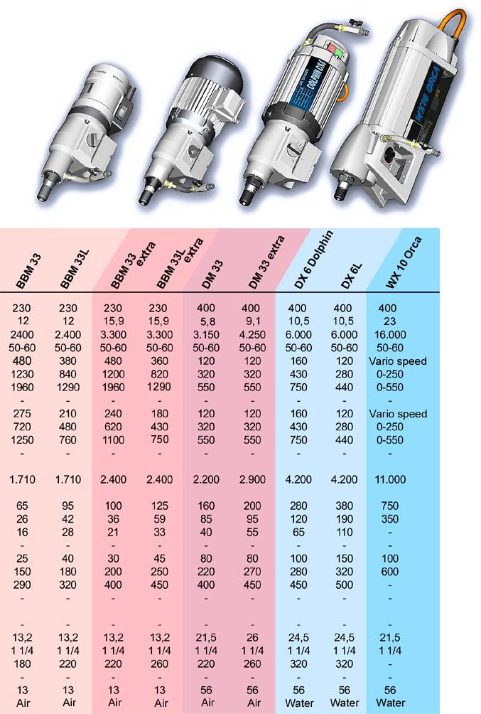
7 4.0 Main dimensions and technical data 4.1 Dimensions 4.2 Technical data Rated voltage 230 V Current consumption 10,5 A Power requirement 2300 W Frequency Hz Idling speed 720 / 1890 / 3960 min -1 Full speed 450 / 1200 / 2500 min -1 Output rating 1650 W Torque 36 / 19 / 10 Nm Drilling diameter mm Weight 6,5 kg Core bit connection UNC 1 ¼ Overload coupling torque 17 Nm 7
8 4.3 Noise emissions and vibrations [EN 50144] Noise level Noise level Vibration 5.0 Commissioning db(a) db m/s < 2,5 Check that the mains voltage is identical to the voltage specified on the model plate. Secure the core drill and the water collector to the drilling stand with its reverse block. The drilling stand should be as rigid as possible and have precise, low-play guides. Ensure that the core drill axis is parallel to the axis of the drilling stand. Insert the core bit and set the speed. The setting instructions are on page 12. Connect the water supply. Important: Do not exceed the maximum water pressure of 3 bar. Connect the core drill to the mains using a residual current-operated circuit-breaker box and 1 h coded plug or a PRCD safety switch. Only use three-core extension cables with a protective conductor and an adequate cross-section. If the cross-section is too low, you may lose excessive power and result in the motor and cable overheating. An extension cable must have an overload cut-out switch. Recommended cable cross-sections: Rated current = 10,5 A Cable length m 7, Cable cross section mm 2 2,5 2,5 2,5 2,5 2,5 4 Ensure that you have sufficient cooling water for drilling. Only use pure tap water, do not use dirty or waste water. Adjust the feed speed to the core bit diameter and the drive rating of the core drill so that the rated current is not exceeded. 8
9 5.1 Changing gear Warning Never change gear using force and only do so when the machine is slowing down or at a standstill. To change into the next higher or lower gear, move the gear-change lever through an angle of approx. 50. If necessary (if the gear is difficult to engage), turn the drive spindle briefly by hand until the gear engages easily. Do not use any tools (pliers, hammer, etc.) to change gear since otherwise gear damage is a natural consequence. 5.2 Safety coupling The values set out in the table are theoretical values and may be used to provide a rough guide for gear changing. Since a whole range of other parameters also plays a major role in adjusting the speed, we cannot offer any guarantee if the tool is damaged when using the values in the table. Drilling work for which the speeds are outside the range of the core drill (values printed in italics), should only be completed with extreme care and by trained personnel. 5.3 Core bits All core bits with a connection thread of 1 ¼ UNC can be used. Adapters can be supplied to allow core bits with other connection systems to be used. Only use core bits that are suitable for the type of stone. You will keep the core drill in good condition if you only use core bits that are concentric and not deformed ones. Ensure that the diamond segments have an adequate undercut against the core bit body. Warning To use wrong tools or accessories is danger for your life. 5.4 To change a core bit The drill spindle has a right-handed thread. Always use a 32 mm open-ended spanner to hold against the drill spindle. Never release the core bit with (hammer) blows since this will damage the core drill. The core bit can be removed more easily if you apply a little waterproof grease to the drill spindle thread. 9
10 6.0 Safety instructions Important Only use the core drill under supervision. Disconnect the mains plug and check that the switch has been turned off, - if you intend to leave the core drill unsupervised, - for attachment and disconnection work, - if the voltage drops (below 200 V), - for adjustments or for fitting an accessory, Switch off the machine if it stops for any reason. This will prevent its starting suddenly when it is not under supervision. Do not use the tool if - part of the casing is missing or defective, - If water drips out of the overflow hole, stop work and have the core drill inspected by an authorised service contractor. - Only drill above your head with suitable safety equipment (water collector), RCD and transformer protection class II. - Connect dust extraction if required. - After a fault do not switch on the machine again until the core bit can be turned easily. - Check the area you wish to drill with a line detector to prevent drilling through electric cables, water or gas lines, etc. - the switch, lead or plug connector has suffered damage (conduct a visual inspection every day). - Cooling water must not be allowed to ingress into the motor or the electrical components when operating the core drill in any position. Do not expose the tool to rain and use not in humidity or wet environment. Use a good lightning. Do not use the tool near flammable fluids or gase air mixes. 10
11 7.0 Servicing and care Warning Disconnect the mains plug before commencing any servicing or repair work. You must have the core drill checked by an electrician after every repair (statutory regulation pursuant to VBG4 since ). 7.1 Daily care Ensure that no water is emitted from the overflow hole. This will cause gear damage and may adversely affect the electrical safety of the core drill. If water is emitted, see assistance from an authorised service outlet. Visual inspection for damage to the switch, connection lead or plug connector After completing the drilling work clean the core drill. Grease the core bit mounting thread. The ventilation slits must always be clean and open. Ensure that during the cleaning process, no water gets into the core drill. To maintain the seal, oil the drilling spindle as follows - Disconnect the core drill from the water supply. Open the water connector shut-off cock, add several drops of oil, close the shut-off cock, add several drops of oil to the overflow hole and turn the machine briefly by hand. 7.2 After approx. 150 hours of use After the first 150 hours of use, the gearbox oil must be changed. 7.3 After approx. 250 hours of use Have the carbon brushes checked, and replaced if necessary, by an electrician. - Remove the screws (17). Pull the cap (14) off the motor casing (2). Remove the carbon brushes screws (9), raise the carbon brushes retaining springs and take out the carbon brushes (8). Clean the carbon brush holder and collector with a paintbrush. - Fit new carbon brushes following the above instructions in reverse. Position the cap (14) and secure it with the screws (17). Fit the cap (14) on the motor casing (2) by tapping it gently with a rubber mallet or the like. Tighten the screws (17). Release the stress by tapping the cap (2) twice. Avoid adjusting the carbon retaining springs. Only use original spare parts. 7.4 Quarterly Have the cable, switch and plug connectors inspected by a specialist (regulation pursuant to VBG4) and document this inspection. Changing the gearbox oil will produce a considerably increase in the service life of the gear. 11
12 8.0 Speed adjustment dependent on the cutting speed [m/s] rd gear rd gear rd gear rd gear rd gear rd gear rd gear rd gear rd gear or or or or or or or or or nd gear or or or or or or st gear st gear st gear st gear st gear st gear st gear st gear st gear st gear st gear st gear st gear Bit capacifity ø concrete concrete rock [mm] reinforced The values set out in the table are theoretical values and may be used to provide a rough guide for gear changing. Since a whole range of other parameters also plays a major role in adjusting the speed, we cannot offer any guarantee if the tool is damaged when using the values in the table. Drilling work for which the speeds are outside the range of the core drill (values printed in italics), should only be completed with extreme care and by trained personnel. 12
13 9.0 Warranty In keeping with our terms of sale, we offer a warranty for six months from the date of sale. This refers to the free repair of material and workmanship defects, which were verifiably caused before the sale. An original purchase document must always be submitted in case of a warranty claim. It has to contain the full address of the dealer, the date of purchase and the type designation of the product. The operating instructions of the particular product and the safety instructions must have been followed. Damages resulting from operational faults cannot be acknowledged as warranty cases. The products of the manufacturer have been developed and produced for specific applications. No warranty claim is accepted in case of non-compliance with the due employment according to the operating instructions, in case of the employment for other purposes than originally intended or the employment of inadequate accessories. The periodical maintenance and cleaning of the products according to the directions of the operating instructions is absolutely necessary. The intervention of third persons (opening the machine) renders any warranty claim void. Maintenance and cleaning operations cannot be claimed on the basis of warranty. Make sure only original spare parts and original accessories are used. They are available at the authorized specialized product dealer. If non-original parts are used, consequential damages and increased hazard cannot be ruled out. The producer is not liable for such damages. Disassembled or partially disassembled hand saws and those repaired with non-original parts are excluded from the warranty. Certain components, such as carbon brushes, ball bearings, switches, power-supply lines, gaskets, etc., are exposed to usage dependent or to normal wear. These wearing parts are not object of this warranty. Wearing parts are marked on the spare parts lists. 13
14 10.0 General safety instructions 1. Read and follow these instructions before you use the tool. Keep these safety instructions in a safe place. 2. Keep your workplace tidy. Untidiness in the workplace can cause accidents. 3. Protect yourself from electric shocks. Refer to the applicable regulations. Avoid physical contact with earthed parts, such as pipes, heaters, furnaces and refrigerators. 4. Keep children away. Do not allow other people to touch the tool or cable, keep them away from where you are working. 5. Keep your tools in a safe place. Unused tools should be kept in a dry, locked room out of the reach of children. 6. Do not overload your tool. It will work better and more safely in the specified capacity range. 7. Use the correct tool. Do not use tools that are too weak or mounted tools for heavy work. Do not use tools for purposes and work for which they have not been designed. 8. Wear suitable clothing. Do not wear excessively baggy clothing or jewellery, which may be caught by moving parts. For working outdoors, we recommend the use of rubber gloves and sturdy shoes. Wear a hairnet if you have long hair. 9. Use goggles. Use a breathing mask for work that generates dust. 10. Do not use the cable for any purpose other that that for which it is designed. Do not carry the tool by the cable and do not use it to pull the plug out of the socket. Protect the cable from heat, oil and sharp edges. 11. Check the connection lead and plug every time before you use the tool for signs of damage. If they are damaged, have them replaced by a specialist. Always keep the connection lead away from the working area of the machine. 12. Secure the workpiece. Use clamps or a vice to hold the workpiece. This will make it more secure that if you hold it in your hand and will allow you to use both hands to control the machine. 13. Do not overstretch yourself. Avoid abnormal body positions. Ensure that you have a stable area on which to stand and keep your balance at all times. 14. Look after your materials with care. Keep your tools sharp and clean so that they produce good safe results. Check the plug and cable at regular intervals and have them replaced by a specialist if they suffer any damage. Check the extension cable at regular intervals and replace damaged cables. Keep the handles free of oil and grease. 15. Disconnect the mains plug from the supply when the tool is not in use and when changing the tool. 15. Do not leave a tool spanner on the tool. Before switching on the tool check that the wrench and setting tools have been removed. 16. Avoid the machine starting when you do not intend it to. Do not carry a tool that is connected to the mains supply with your finger on the switch. Ensure that the switch is turned off when you connect the tool to the mains supply. 18. Electric tools outdoors and in wet areas: Mobile tools which are used outdoors should be connected to the mains supply using a residual-current circuit breaker or the like for added safety. This is particularly important when working with freehand tools. If there is a water supply, you should use an isolation transformer and a voltage supply of 115 V; please specify in your order. 19. For outdoors work, only use extension cables, which are approved for this purpose and marked accordingly. 20. Be vigilant at all times. Watch your work. Proceed sensibly. Do not use the tool if you are not concentrating fully on what you are doing. 21. Important: Safety equipment (such as overcurrent protection devices, undervoltage trips, safety couplings etc.) are tools but do not offer guaranteed safety. As a responsible manufacturer we tailor these tools to each other so that they offer the best possible protection. But without the care and caution of the use, these tools may even cause damage it they are not used properly. Have the slip couplings, in particular, checked during the quarterly inspection to ensure that it is correctly adjusted and functions properly. This inspection should be conducted by the manufacturer or an authorised service outlet and documented. 14
15 22. Check the machine every day for signs of damage, conduct a visual inspection: Before reusing the tool, carefully check the safety equipment or slightly damaged parts to ensure that they offer perfect and proper function. Check that all moving parts function correctly, that they do not jam and that none of the parts are damaged. All parts must be correctly fitted and satisfy all the conditions to ensure the perfect operation of the tool. Damaged safety equipment and parts must be repaired or replaced properly by a specialist service contractor. Do not use any tools, which cannot be switched on and off using the switch. Pay particular attention to ensuring electrical safety: Cables? Plugs? Switches? Do all the components satisfy safety regulations? 23. Repairs may only be completed by trained personnel. Before being used for the first time and after all repair work, the safety of electric tools must be checked by an electrician pursuant to VBG 4, 5. This inspection must also be conducted and documented at regular intervals at least once per year. 24. Please note that as the operator you are responsible for complying with any additional regulations. For example if electric tools are used in a wet and/or damp environment, the regulations of the Stone and Earth Professional Association must be satisfied. 25. Electrical safety and fire safety: We now also recommend the additional safety and fire safety for all out tools, as set out in the new version of VDE 0100 which can be achieved by using low cost residual current-operated circuit-breakers or DI/PRCD switches. 15
16 11.0 Spare parts list 11.1 Motor complete 16
17 Item Art. No. Description No Motor complete Motor casing Magnet casing Washer Spring washer Flat head screw Distance ring Hull Brush bridge Carbon brush 2 ** Spring washer Cheese-head screw Allen bolt Air baffle disc Switch box complete Switch box Toggle switch Strain-relief clamp Cross recessed pan head tapping screw Cable grommet 1 ** Interference-suppression capacitor Connection cable complete 1 ** Connection cable M conf Safety switch Connection cable S conf Plug Allen bolt Intermediate cover Grooved ball bearings 1 ** Needle sleeve 1 ** O ring 1 ** Shaft sealing ring 1 ** Sleeve Grooved ball bearings 1 ** Armature Grooved ball bearings 1 ** Ball bearing compensating disc Bearing cap complete Bearing cap Insulation 1 ** Spirit level Allen bolt Information plate 1 Wearing parts** 17
18 11.2 Gear complete 18
19 Item Art. No. Description No Gear complete Gear casing Control grip 1 ** O ring Sleeve Switch handle complete Fillister self-tapping screw Shaft sealing ring 1 ** Shaft sealing ring 2 ** Locking ring 1 ** Grooved ball bearing 1 ** Locking ring 1 ** Drill spindle complete Compression spring Ball Locking ring 2 ** Loose wheel complete Control wheel / Loose wheel Bearing sleeve 1 ** Adjusting washer Locking ring 1 ** Parallel key Control wheel complete Control connector Parallel key Control wheel Control wheel Grooved ball bearing 1 ** Reduction shaft complete Reduction shaft Parallel key Speed wheel Brake disc 2 ** Reduction wheel complete Reduction wheel Bearing sleeve 1 ** Compression washer Disc spring Hexagonal nut Sealing ring Sealing screw Cylindrical pin Locking washer Allen bolt Water connection complete 1 ** Hose complete Sealing ring Ball cook complete Sealing ring Slot-in nipple O ring Gearbox oil 0,3 l 1 ** Allen bolt 1 Wearing parts ** 19


20 11.3 Connection cables and accessories 20
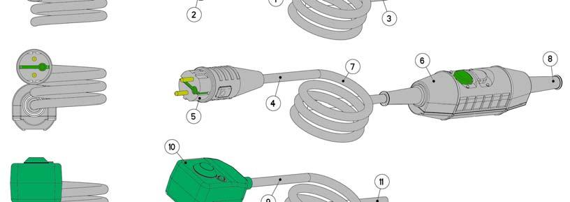
21 Item Article number Description No. Plugs (no more permitted) Schuko Connection cable compl Plug Connection cable, finished 1 Plugs for Germany, France, Italy PRCD Connection cable compl Plug Safety switch Connection cable S compliant Connection cable M compliant 1 Plugs (replaced through PRCD Id-Nr ) DI 9 - Connection cable compl Plug Connection cable, finished 1 Plugs (with insulation transformer and drilling motor 115V) 12h Connection cable compl Plug, 12h Connection cable, finished 1 Plugs (standard with Fi-Box IP44) 1h Connection cable compl Plug, 1h Connection cable, finished 1 Plugs (Italy with Fi-Box IP44) 6h Connection cable compl Plug, 6h Connection cable, finished 1 21

22 From our produkt spectrum 22
23 23
DR. BENDER GmbH Innovative Elektrowerkzeuge. Manual for 115 V
 DR. BENDER GmbH Innovative Elektrowerkzeuge Manual for drilling motor BBM 33 L extra 115 V Valid from 07.2004 Art.-Nr. 200515 Subject to alterations All rights reserved DR. BENDER GmbH D-75382 Althengstett
DX 6 L DOLPHIN. DR. BENDER GmbH Innovative Elektrowerkzeuge. Manual for drilling motor 400 V 3~
 DR. BENDER GmbH Innovative Elektrowerkzeuge Manual for drilling motor DX 6 L DOLPHIN 400 V 3~ Valid from 09.2004 Art.-Nr. 200679 Subject to alterations All rights reserved DR. BENDER GmbH D-75382 Althengstett
DR. BENDER GmbH Innovative Power Tools. Operating Manual Drive unit Beluga sxc / SXD HF III
 DR. BENDER GmbH Innovative Power Tools Operating Manual Drive unit Beluga sxc / SXD HF III Issued 11.2015 Subject to change All rights reserved DR. BENDER GmbH D-75382 Althengstett Tel 07051-9291-0 Fax
DR. BENDER GmbH Innovative Power Tools. Operating Manual Powerbox PB RX / SX 12 HF III
 DR. BENDER GmbH Innovative Power Tools Operating Manual Powerbox PB RX / SX 12 HF III Issued 08.2015 PB RX / SX 12 Art. no. 102405 Subject to change Alle Rechte vorbehalten / All rights reserved DR. BENDER
INSTRUCTION MANUAL ANGLE GRINDER PT W
 INSTRUCTION MANUAL ANGLE GRINDER PT50360 4½ INCHES 120V 60Hz 600W 5A 12,000 rpm C US Note : Before operating this tool, read this manual and follow all safety rules and operating instructions. This electric
6 x 10 Belt Disc Sander
 6 x 10 Belt Disc Sander FOR HELP OR ADVISE ON THIS PRODUCT PLEASE CALL OUR CUSTOMER SERVICE HELP LINE : 01509 500400 THE MANUFACTURER RESERVES THE RIGHT TO ALTER THE DESIGN OR SPECIFICATION TO THIS PRODUCT
Disc Grinder Model G 18MR G 23MR G 23MRU
 Disc Grinder Model G 18MR G 23MR G 23MRU Handling instructions G23MR NOTE: Before using this Electric Power Tool, carefully read through these HANDLING INSTRUCTIONS to ensure efficient, safe operation.
HST-BL-2830MS & HST-BL-2830MS-USA
 HST-BL-2830MS & HST-BL-2830MS-USA Release date: 02/2017 High - System - Technik Im Martelacker 12 D-79588 Efringen-Kirchen Phone 0 76 28-91 11-0 Fax 0 76 28-91 11-90 E-Mail: info@hs-technik.com Web: www.hs-technik.com
ELECTRIC CAR POLISHER
 ELECTRIC CAR POLISHER MODEL NO: CP254 PART NO: 6462108 OPERATION & MAINTENANCE INSTRUCTIONS LS0610 INTRODUCTION Thank you for purchasing this CLARKE electric car polisher. Before attempting to use this
Disc Grinder PDA-100H. Handling Instructions. Read through carefully and understand these instructions before use.
 Disc Grinder PDA100H Handling Instructions Read through carefully and understand these instructions before use. 1 2 4 6 8 1 2 3 4 5 6 7 9 0 8 L K I G 1 3 5 7 15 ~30 A B 1 A D 5 9 8 B C 0 1 2 J 4 5 8 0
BENCH GRINDER MODEL NO. OZBG150WA
 BENCH GRINDER 150mm MODEL NO. OZBG150WA OPERATING INSTRUCTIONS To view our entire range visit www.ozito.com.au SPECIFICATIONS MODEL NO. OZBG150WA Input Power: 150W Input Voltage: 230V ~ 50Hz No Load Speed:
MANUAL. Single charger
 MANUAL Single charger HST-PR-2830 & HST-PR-2830USA for HS-Technik batteries HST-PR-18xx HST-PR-14xx issue date: November 2016 Table of contents Page 1. Basic information...3 1.1. Purpose of this document...3
PURE SINE WAVE DC TO AC POWER INVERTER
 PURE SINE WAVE DC TO AC POWER INVERTER 60S-12A / 60S-24A 60S-12E / 60S-24E 100S-12A / 100S-24A 100S-12E / 100S-24E 150S-12A / 150S-24A 150S-12E / 150S-24E Instruction manual SINE WAVE INVERTER Please read
ORIGINAL INSTRUCTIONS
 OPERATION & MAINTENANCE INSTRUCTIONS CBB200 Shown here BUFFER/POLISHER MODEL NO: CBB150, CBB200 PART NO: 6500485, 6500490 ORIGINAL INSTRUCTIONS LS0818 - ISS 1 INTRODUCTION Thank you for purchasing this
Installation manual wall-mounted distributor
 EN Installation manual wall-mounted distributor EN 60003233 Issue 11.2016 2016-14-11 Table of contents 1 About this manual 3 1.1 Structure of the warnings 3 1.2 Symbols used 4 1.3 Signal words used 4 2
ELECTRIC ENGRAVER 15W WARRANTY INSTRUCTION MANUAL SPECIFICATIONS WHAT S IN THE BOX. ozito.com.au. Electric Engraver
 IN ORDER TO MAKE A CLAIM UNDER THIS WARRANTY YOU MUST RETURN THE PRODUCT TO YOUR NEAREST BUNNINGS WAREHOUSE WITH YOUR BUNNINGS REGISTER RECEIPT. PRIOR TO RETURNING YOUR PRODUCT FOR WARRANTY PLEASE TELEPHONE
Operating Instructions
 Operating Instructions Index 004 DME20PU DME20PW Original operating instructions 10998334 en / 29.05.2017 Congratulations! With a Hydrostress unit from TYROLIT you have chosen a tried and tested piece
OWNER S OPERATING MANUAL
 OWNER S OPERATING MANUAL ARC 140 AMP WELDER TABLE OF CONTENTS Page Safety instructions 3-4 Inverter Arc Welder 5 Welder Information 5 Arc 140 AMP welder set up 6 Assembly instructions 6 Operation 7 Welding
WHAT S IN THE BOX METAL CUTTING SHEARS. Metal Cutting Shears 500W INSTRUCTION MANUAL SPECIFICATIONS. Hex Key. Max. Thickness: ozito.com.
 WHAT S IN THE BOX METAL CUTTING SHEARS 500W INSTRUCTION MANUAL SPECIFICATIONS Motor: No load speed: Max. Thickness: Tool weight: 500W 0 1,600 rpm 1.2mm 2.2kg Metal Cutting Shears Hex Key ozito.com.au MCS-5000
Rotary feed-through DDF-S/-KS
 Translation of the Original Operating Manual Rotary feed-through DDF-S/-KS Assembly and Operating Manual Superior Clamping and Gripping Imprint Imprint Copyright: This manual remains the copyrighted property
Operating instructions ErgoPack 600 E
 Operating instructions ErgoPack 600 E Operation of the device is only permitted if the operating instructions have been carefully read and understood before use! Declaration of conformity EU declaration
Instruction Manual 4.0V Li-Ion Screwdriver. Part #: ECLIPSE ENTERPRISES, INC Chula Road, Amelia Court House, VA 23002, U.S.
 Instruction Manual 4.0V Li-Ion Screwdriver Part #: 902-588 ECLIPSE ENTERPRISES, INC. 13302 Chula Road, Amelia Court House, VA 23002, U.S.A 2 3 Intended use Your ECLIPSE ENTERPRISES, INC. 902-588 screwdriver
Installation and Operation Instructions. VAG ROTOP Portable Electric Drive
 Installation and Operation Instructions VAG ROTOP Portable Electric Drive KAT-B 5551 Edition 1-01/2018 Content 1 General 3 1.1 Safety 3 1.2 Proper use 3 2 Transport and Storage 3 2.1 Transport 3 2.2 Storage
18V CORDLESS STAPLER/NAILER
 18V CORDLESS STAPLER/NAILER MODEL NO: CONSN18LI PART NO: 6487055 OPERATION & MAINTENANCE INSTRUCTIONS LS1213 INTRODUCTION Thank you for purchasing this CLARKE product. Before attempting to use this product,
Installation manual portable distributors
 EN Installation manual portable distributors EN 60003206 Issue 11.2016 15/11/2016 Table of contents 1 About this manual 3 1.1 Structure of the warnings 3 1.2 Symbols used 4 1.3 Signal words used 4 2 Intended
AXIAL FANS Axis / Tubo OPERATION MANUAL
 TUBO-M AXIS-QA AXIS-Q AXIS-QR AXIS-F AXIS-QRA AXIAL FANS Axis / Tubo OPERATION MANUAL Axis / Tubo www.blaubergventilatoren.de CONTENT 3 Introduction 3 General 3 Safety rules 3 Transport and storage requirements
18V CORDLESS DRILL MODEL NO: CON18LiC
 18V CORDLESS DRILL MODEL NO: CON18LiC PART NO: 6479531 OPERATION & MAINTENANCE INSTRUCTIONS ORIGINAL INSTRUCTIONS GC0817 - ISS 2 INTRODUCTION Thank you for purchasing this CLARKE Cordless Drill. Before
Disc Grinder Model G 18SCY G 18SEY G 18UBY G 23SCY G 23SEY G 23UBY
 Disc Grinder Model G 18SCY G 18SEY G 18UBY G 23SCY G 23SEY G 23UBY Handling instructions G23SEY NOTE: Before using this Electric Power Tool, carefully read through these HANDLING INSTRUCTIONS to ensure
ELECTRIC LIFTING HOIST
 ELECTRIC LIFTING HOIST COMPLIES TO AS 1418 STANDARDS KP1201 125/250KG KP1202 400/800KG ED 2 / JULY / 15 TYPE 2 1 Table of Contents 1 Know Your Product...2 Electric Lifting Hoist Safety Instructions...3
eclipse Instruction Manual 4.0V Li-Ion Screwdriver Part #:
 eclipse Instruction Manual 4.0V Li-Ion Screwdriver Part #: 902-588 Test Equipment Depot - 800.517.8431-99 Washington Street Melrose, MA 02176 TestEquipmentDepot.com Test Equipment Depot - 800.517.8431-99
Power Paint Scraper 200W CPS-200. To view the full range visit: Instruction Manual 3 Year Replacement Warranty
 Power Paint Scraper 200W Instruction Manual 3 Year Replacement Warranty CPS-200 WARNING! Read all safety warnings and all instructions Failure to follow the warnings and instructions may result in electric
Cordless High Speed Drill
 ENGLISH Cordless High Speed Drill MODEL 6503D 00039 I N S T R U C T I O N M A N U A L WARNING: For your personal safety, READ and UNDERSTAND before using. SAVE THESE INSTRUCTIONS FOR FUTURE REFERENCE.
Power Carver 50W CPC-050. To view the full range visit: Instruction Manual 3 Year Replacement Warranty
 Power Carver 50W Instruction Manual 3 Year Replacement Warranty CPC-050 WARNING! Read all safety warnings and all instructions. Failure to follow the warnings and instructions may result in electric shock,
Lifting device for standard removable versions
 Operating manual Lifting device for standard removable versions Type 1889 haacon hilft heben haacon hebetechnik gmbh Josef-Haamann-Str. 6 D-97896 Freudenberg/Main Tel: +49 (0) 93 75/84-0 Fax: +49 (0) 93
TIDALFLUX 2300 F Quick Start
 Quick Start Electromagnetic flow sensor for partially filled pipes The documentation is only complete when used in combination with the relevant documentation for the signal converter. KROHNE CONTENTS
Instruction Manual CORDLESS DRILL & DRIVER 18V. Model SROM 1170
 Instruction Manual CORDLESS DRILL & DRIVER 18V Model SROM 1170 Product Features: Dear Valued Customer, Thank you for purchasing this Samson Power Tool. We are dedicated to providing quality Samson Power
Cordless Rechargeable Saw Instructions for Use
 Technical data Voltage: DC 10.8V Weight: 1.25Kg Stroke rate: 0-2100/min Stroke: 15mm Cutting capacity: max diameter in wood 80mm / in soft metal 7mm Charging time: Between 5.0-5.5 Hours Battery: 1.3Ah
TE 700-AVR. English. Printed: Doc-Nr: PUB / / 000 / 05
 TE 700-AVR English 1 Information about the documentation 1.1 About this documentation Read this documentation before initial operation or use. This is a prerequisite for safe, trouble-free handling and
Ordering designation: G(Type) - (Stroke) - (Eye bolt) - (Cable length) - (Options) Legend:
 - (Stroke) - (Eye bolt) - (Cable length) - (Options) Legend:") General technical data: 1.) Anodised aluminium housing with a connecting rod made of aluminium (in the case of motor types G..B, G..C, G..D and G..E, the connecting rod is Ø18, for all other motor types
General technical data: 1.) Anodised aluminium housing with a connecting rod made of aluminium (in the case of motor types G..B, G..C, G..D and G..E, the connecting rod is Ø18, for all other motor types
Yellow & Green connections to ensure that none is loose.
 instructions for: power belt sander model no: SM100 Thank you for purchasing a Sealey product. Manufactured to a high standard this product will, if used according to these instructions and properly maintained,
SIP Direct Drive Oil-Lube Air Compressors - Operating & Maintenance Instructions
 SIP Direct Drive Oil-Lube Air Compressors - Operating & Maintenance Instructions Please read and fully understand the instructions in this manual before operation. Keep this manual safe for future reference.
1200W CaR PoliSheR en RS4900
 1200W Car Polisher RS4900 RS4900 8 1 2 7 3 4 5 6 A B flat nozzle C D E F 1200W Car Polisher RS4900 G H flat nozzle I J K L 4 1200W Car Polisher COMPONT LIST 1 2 3 4 5 6 7 Variable speed control Switch
Assembly and Maintenance Manual Type ASNU
 Assembly and Maintenance Manual Type ASNU Hatschekstr.36 69126 Heidelberg Germany Tel +49(0)6221 30470 Fax +49(0)6221 304731 info@stieber.de www.stieber.de Date of issue: 30.05.2018 GB Revision: 0 U:\EngUsers\!ProduktDoku\1AAA_Einbauerklaerung_Wartungsanleitung_Konformitaetserklaerung\1AAA_Wartungsanleitungen\Orginal_Worddatei\_ASNU.docx
4V LITHIUM-ION SCREWDRIVER OWNER S OPERATING MANUAL
 CSD-4107BG 4V LITHIUM-ION SCREWDRIVER OWNER S OPERATING MANUAL Your screwdriver has been engineered and manufactured to our high standard for dependability, ease of operation, and operator safety. When
Disassembly. 1 Pull off the QUIK-LOK cable from the machine.
 Special Tools Require Important! Torx TX0 bit 0 0 Screwdriver Torx 0 0 0 Forcing Discs 0 Before beginning the maintenance work, perform an initial check with a high voltage test according to VDE (see chapter
RMT1201. ORIGINAL INSTRUCTIONS Cordless Multi-Tool
 RMT1201 ORIGINAL INSTRUCTIONS Cordless Multi-Tool Important! It is essential that you read the instructions in this manual before operating this machine. Subject to technical modifications. Safety GENERAL
Cordless Screwdriver
 ENGLISH Cordless Screwdriver MODEL 6796D MODEL 6796FD MODEL 6797D MODEL 6797FD MODEL 6798D MODEL 6798FD 00260 I N S T R U C T I O N M A N U A L WARNING: For your personal safety, READ and UNDERSTAND before
TE 1500-AVR. English. Printed: Doc-Nr: PUB / / 000 / 03
 TE 1500-AVR English 1 Information about the documentation 1.1 About this documentation Read this documentation before initial operation or use. This is a prerequisite for safe, trouble-free handling and
These operating instructions apply for: NCX 380 NCZ 300 NCX 480 NCZ 370 NCX 580 L NCZ 480 NCX 660 K NCZ 560 NCZ 660 NCZ 800
 Original instructions Operating Instructions for May 2010 Electric Internal Vibrators BA No. 1092E Series NCX and NCZ These operating instructions apply for: NCX 380 NCZ 300 NCX 480 NCZ 370 NCX 580 L NCZ
W6VB3 W8VB2. Handling instructions
 Screw Driver Model W 6VM W 6V4 W 6VA4 W 6VB3 W 8VB2 Handling instructions W6VM W6V4 W6VA4 W6VB3 W8VB2 Note: Before using this Electric Power Tool, carefully read through these HANDLING INSTRUCTIONS to
PRODUCT MANUAL TILE CUTTING MACHINE. . Operation. Parts List and Diagram SPECIFICATIONS CAUTION:
 FLORCRAFTT TM PRODUCT MANUAL SKU NUMBER 709-4242 SERIAL NUMBER: CAUTION: FOR YOUR OWN SAFETY READ INSTRUCTION MANUAL COMPLETELY AND CAREFULLY BEFORE OPERATING THIS 7 TILECUTTING MACHINE SPECIFICATIONS
Pro Booster 802Li. Please read and fully understand the instructions in this manual before operation. Keep this manual safe for future reference.
 Please dispose of packaging for the product in a responsible manner. It is suitable for recycling. Help to protect the environment, take the packaging to the local amenity tip and place into the appropriate
Technical Documentation
 Technical Documentation Product manual Holding brake controller Document: 0198441113316 Edition: V1.00, 03.2006 Important information The drive systems described here are products for general use that
OWNER S OPERATING MANUAL
 OWNER S OPERATING MANUAL WELD AND CUT ARC/TIG INVERTER PLASMA 30 PLASMA CUTTER TABLE OF CONTENTS Safety instructions 3-4 Weld & Cut ARC/TIG and Plasma Cutter 5 Page Installation 6 Welder Information 6-8
BENCH GRINDER MODEL NO: CBG6250
 CBG6250 Bench Grinder.fm Page 1 Thursday, November 10, 2011 3:26 PM BENCH GRINDER MODEL NO: CBG6250 PART NO: 6500522 OPERATION & MAINTENANCE INSTRUCTIONS LS1111 CBG6250 Bench Grinder.fm Page 2 Thursday,
Bowl feeder WV401-1 / Translation of operating and installation instructions
 Bowl feeder WV401-1 / 402-1 Translation of operating and installation instructions Copyright by Afag GmbH This operation instruction applies to: Bowl feeder WV401-1 Bowl feeder WV402-1 Type 230 V / 50
Instruction Manual. CORDLESS DRILL 18V Li-ion WITH IMPACT FUNCTION. Model SROM 1172
 Instruction Manual CORDLESS DRILL 18V Li-ion WITH IMPACT FUNCTION Model SROM 1172 Our tool range has you covered for DIY. Whatever the job, make light work of it with MAKO tools. Product Features: 1. Keyless
RPS1215 ORIGINAL INSTRUCTIONS. Cordless Pruner
 RPS5 ORIGINAL INSTRUCTIONS Cordless Pruner Important! It is essential that you read the instructions in this manual before assembling, operating and maintaining the product. Subject to technical modification.
HCS14/16/18 Hydraulic Cut-off Saw. Prior to Operation. We thank you for choosing a HYCON cut-off saw.
 Prior to Operation HCS14/16/18 Hydraulic Cut-off Saw From serial No. 0164 Revised September 2003 HYCON A/S Vester Hassingvej 33 DK-9320 Hjallerup Denmark Tel: +45 9647 5200 Fax: +45 9647 5201 Mail hycon@hycon.dk
OPERATOR'S MANUAL. Cat. No. C12 PC. To reduce the risk of injury, user must read and understand operator's manual.
 OPERATOR'S MANUAL Cat. No. C12 PC M12 Cordless Copper Tubing Cutter To reduce the risk of injury, user must read and understand operator's manual. General POWER TOOL SAFETY WARNINGS WARNING Read all safety
TE 2-A22. English. Printed: Doc-Nr: PUB / / 000 / 00
 TE 2-A22 English en 1 Information about the documentation 1.1 About this documentation Read this documentation before initial operation or use. This is a is a prerequisite for safe, trouble-free handling
Subject to change. USERS MANUAL Art.nr. CDM6026 PCD-2400I. NiCd
 UK Subject to change UK USERS MANUAL Art.nr. CDM02 PCD-2400I NiCd 040-2 4 1 2 4 R L EXPLODED VIEW 3 Fig. A Fig. D B 1 2 Fig. B Fig. E 3 10 11 SPARE PARTS LIST PCD-2400I A Fig. C 3 Fig. F REF NR DESCRIPTION
Pneumatic grease pump 50:1 and grease supply system
 Pneumatic grease pump 50:1 and grease supply system 03 591 A411 GB G Operating instructions for Pneumatic grease pump 50:1 Contents 1. General Information 2 1.1 Usage Stipulations 2 1.2 Construction &
SeekTech Inductive Clamp
 Inductive Clamp Manual SeekTech Inductive Clamp! Read this Operator s Manual carefully before using this tool. Failure to understand and follow the contents of this manual may result in electrical shock,
19.2V CORDLESS 2-IN-I COMBO KIT OWNER'S MANUAL
 19.2V CORDLESS 2-IN-I COMBO KIT OWNER'S MANUAL WARNING: Read carefully and understand all INSTRUCTIONS before operating. Failure to follow the safety rules and other basic safety precautions may result
Instruction manual. CSV 402 caravan power supply. Table of contents
 Instruction manual CSV 402 caravan power supply Table of contents 1 Introduction... 2 2 Safety information... 2 2.1 Significae of the warning signs... 2 2.2 General safety instructions... 2 Application
SFC 18 A SFC 22 A English
 SFC 18 A SFC 22 A English en 1 Information about the documentation 1.1 About this documentation Read this documentation before initial operation or use. This is a is a prerequisite for safe, trouble-free
TABLE OF CONTENTS. Section 1 - Important Safety Instructions Section 2 - Grounding Instructions Section 3 - Operator Cautions...
 Light Tools - DC Screwdriver Operation & Maintenance Manual For Models: SKD-2000L/UL/B, SKD-2200L/UL/B, SKD-2300L/UL/B SKD-5200L/UL/B, SKD-5200P/UL/B SKD-5300L/UL/B, SKD-5300P/UL/B Dixon Automatic Tool
SAFETY AND OPERATING MANUAL. Lithium-Ion cordless hammer drill WX372 WX372.1 WX372.9
 SAFETY AND OPERATING MANUAL 2 Original Instructions General Power Tool Safety Warnings WARNING: Read all safety warnings and all instructions. Failure to follow the warnings and instructions may result
Angle Grinder Holder
 Angle Grinder Holder Owner s Manual WARNING: Read carefully and understand all ASSEMBLY AND OPERATION INSTRUCTIONS before operating. Failure to follow the safety rules and other basic safety precautions
8 Inch Benchtop Buffer
 8 Inch Benchtop Buffer Owner s Manual WARNING: Read carefully and understand all ASSEMBLY AND OPERATION INSTRUCTIONS before operating. Failure to follow the safety rules and other basic safety precautions
Turbocharger / A100-L Original assembly instructions English
 Assembly Instructions Turbocharger / A100-L Original assembly instructions English This document is valid for the A100-L series: A165-L, A170-L, A175-L, A180-L, A185-L, A190-L Purpose The assembly instructions
Electric Chainsaw Sharpener
 Electric Chainsaw Sharpener Owner s Manual WARNING: Read carefully and understand all ASSEMBLY AND OPERATION INSTRUCTIONS before operating. Failure to follow the safety rules and other basic safety precautions
Printed: Doc-Nr: PUB / / 000 / 00
 ORIGINAL OPERATING INSTRUCTIONS Hilti HTE-P 33 dispenser It is essential that the operating instructions are read before the tool is operated for the first time. Always keep these operating instructions
CORDLESS TACKER MODEL NO: CCT48 OPERATION & MAINTENANCE INSTRUCTIONS PART NO: LS0414
 CORDLESS TACKER MODEL NO: CCT48 PART NO: 6485070 OPERATION & MAINTENANCE INSTRUCTIONS LS0414 INTRODUCTION Thank you for purchasing this CLARKE product. Before attempting to use this product, please read
Installation and operating instructions. Solar charge controller MPPT 10 A / 20 A Z Z
 Installation and operating instructions Solar charge controller MPPT 10 A / 20 A EN 1 Contents 1. About these instructions... 3 1.1 Applicability... 3 1.2 Users... 3 1.3 Description of symbols... 3 2.
Safety instructions ENGLISH. General power tool safety warnings. (Original instructions)
") FME500 A B C 2 (Original instructions) ENGLISH Intended use Your Stanley Fat Max rotary hammer drill has been designed for drilling in wood, metal, plastics, and masonry as well as for light chiselling
FME500 A B C 2 (Original instructions) ENGLISH Intended use Your Stanley Fat Max rotary hammer drill has been designed for drilling in wood, metal, plastics, and masonry as well as for light chiselling
HDE 500-A22. English. Printed: Doc-Nr: PUB / / 000 / 03
 HDE 500-A22 English 1 Information about the documentation 1.1 About this documentation Read this documentation before initial operation or use. This is a prerequisite for safe, trouble-free handling and
3. Operating instructions: Minor 200
 1. Technical specifications 3. Operating instructions: Minor 200 Copyright 2015 by Endecotts Ltd. 13 1. Setting up Technical specifications SIEVE SHAKER MODEL: Minor 200 General Information The Minor 200
Wilo-Control SC-Fire Jockey
 Pioneering for You Wilo-Control SC-Fire Jockey de en fr Einbau- und Betriebsanleitung Installation and operating instructions Notice de montage et de mise en service nl Inbouw- en bedieningsvoorschriften
Drive Unit e-drive1. Installation instructions 04/2014. English translation of the original German installation instructions
 Drive Unit e-drive1 Installation instructions 04/2014 English translation of the original German installation instructions Contents Foreword... 3 Availability... 3 Structural features in the text... 3
OWNER S OPERATING MANUAL
 OWNER S OPERATING MANUAL MIG 100 GASLESS WELDER TABLE OF CONTENTS Page Safety instructions 3-4 MIG Welders 5 Welder Information 5 Gasless welder set up 6 Operation 6-10 Troubleshooting Guide 11-12 Spare
Analytical Diaphragm Pump Series MP MP06, MP12
 Analytical Diaphragm Pump Series MP MP06, MP12 Instruction Manual Version 1.00.01 Dear customer, we have made up this operating manual in such a way that all necessary information about the product can
Compensation unit AGE-XY 50-80
 Translation of the origninal manual Compensation unit AGE-XY 50-80 Assembly and operating manual Superior Clamping and Gripping Imprint Imprint Copyright: This manual remains the copyrighted property of
Swing Piston Compressors and Vacuum Pumps
 Swing Piston Compressors and Vacuum Pumps NPK 018 AC Pressure NPK 018 DC Pressure NPK 018 AC Vacuum NPK 018 DC Vacuum Operating and Installation Instructions Read and observe these Operating and Installation
Operator's manual. TruTool F 140 (1A1) english
 english") Operator's manual TruTool F 140 (1A1) english Table of contents 1. Safety...3 2. Description...5 2.1 Intended use...6 2.2 Technical data of the TruTool F 140...7 2.3 Lock seams...8 3. Tool assembly...10
Operator's manual TruTool F 140 (1A1) english Table of contents 1. Safety...3 2. Description...5 2.1 Intended use...6 2.2 Technical data of the TruTool F 140...7 2.3 Lock seams...8 3. Tool assembly...10
Turbocharger / TPS-H Original assembly instructions English
 Assembly Instructions Turbocharger / TPS-H Original assembly instructions English This document is valid for the TPS-H series: TPS44-H, TPS48-H, TPS52-H Purpose TPS-H turbocharger The assembly instructions
1/2 HP SUMP PUMP OWNER'S MANUAL
 TM 1/2 HP SUMP PUMP OWNER'S MANUAL WARNING: Read carefully and understand all INSTRUCTIONS before operating. Failure to follow the safety rules and other basic safety precautions may result in serious
Assembly and Maintenance Manual Type AS
 Assembly and Maintenance Manual Type AS Hatschekstr.36 69126 Heidelberg Germany Tel +49(0)6221 30470 Fax +49(0)6221 304731 info@stieber.de www.stieber.de Date of issue: 30.05.2018 GB Revision: 0 U:\EngUsers\!ProduktDoku\1AAA_Einbauerklaerung_Wartungsanleitung_Konformitaetserklaerung\1AAA_Wartungsanleitungen\Orginal_Worddatei\_AS.docx
Angle Grinder. WARNING: For your personal safety, READ and UNDERSTAND before using. SAVE THESE INSTRUCTIONS FOR FUTURE REFERENCE.
 ENGLISH Angle Grinder MODEL GA700, GA700F MODEL GA700S, GA700SF MODEL GA7040S, GA7040SF MODEL GA900, GA900F MODEL GA900S, GA900SF MODEL GA9040S, GA9040SF 00705 DOUBLE INSULATION I N S T R U C T I O N M
Oil-free piston compressors KK and piston vacuum pumps KV
 Oil-free piston compressors KK and piston vacuum pumps KV Installation and Operating Instructions 0678106030L02 1707V003 Contents Important information 1 About this document 2 1.1 Warnings and symbols
SBC12 H Operating instructions Mode d emploi Manual de instrucciones
 *254901* 254901 SBC12 H Operating instructions Mode d emploi Manual de instrucciones Safety Precautions Read all Instructions GENERAL SAFETY RULES FOR ALL BATTERY OPERATED TOOLS WARNING! Read and understand
Operating instructions Rotary actuators M135 M140 M150 M180. June 2012 / / EN
 Operating instructions Rotary actuators M135 M140 M150 M180 June 2012 / 118614 / EN General information General information Proof of amendment Copyright Subject to alterations Manufacturer Version Date
MULTI PURPOSE SAW 500W INSTRUCTION MANUAL SPECIFICATIONS. ozito.com.au WHAT S IN THE BOX MSW Multi-purpose Saw. Blades x 3.
 WHAT S IN THE BOX MULTI PURPOSE SAW 500W INSTRUCTION MANUAL SPECIFICATIONS Input: Voltage: No Load Speed: Stroke Length: Blade Fitment: Cutting Capacity: Weight: ozito.com.au 500W 230-240V ~ 50Hz 500-3000
Instruction manual Electric glass door lock Touch-to-open
 Instruction manual Electric glass door lock Touch-to-open OPERATING INSTRUCTIONS Touch to open electric glass door lock Operating instructions draft 09-2017_v1 Content 1 General 1.1 Performance Description
Linear unit, pneumatic KHM 40
 Translation of original operating manual Linear unit, pneumatic KHM 40 Assembly and Operating Manual Superior Clamping and Gripping Imprint Imprint Copyright: This manual remains the copyrighted property
Braking Devices BR 230/ Assembly- and Commissioning Instructions
 electronic Braking Devices BR 230/400-10...400 Assembly- and Commissioning Instructions Quality is our Drive. BR 230/400-10...400 1 as per 04/10 11600.10001 Table of Contents Page 1. Safety notes 3 2.
Ferm Cordless Drill FDC-1200K. Art.nr Screwfix Art.nr Ferm BV P.O. Box AC Genemuiden NL
 UK Subject to change USER S MANUAL Document Ref: FDC-1200K/00000/AAA00/issue 0/Month 00 Copyright These instructions are the sole property of Ferm-Omega Tools and may not be reproduced Ferm Cordless Drill
16 Inch Surface Cleaner
 16 Inch Surface Cleaner Owner s Manual WARNING: Read and understand all instructions, warnings, and cautions before using this product. Failure to follow the instructions, warnings, and cautions may result
SPECIFICATIONS MODEL NO. OZBG150WA
 SPECIFICATIONS MODEL NO. OZBG150WA Input Power: 150W Input Voltage: 230V ~ 50Hz No Load Speed: 2950/min Wheel Diameter: 150mm (6 ) Wheel Thickness: 16mm Wheel Bore: 12.7mm Protection Class: 1 (earthed