Air Valves Engineering Creative Solutions for Fluid Systems Since 1901
|
|
|
- Anthony Hunter
- 6 years ago
- Views:
Transcription

1 Air s Engineering Creative Solutions for Fluid Systems Since 1901
2 401 South Highland Avenue Aurora, Illinois phone: Table of Contents AirPro Max Air s Air Release Data & Sizing Guide... 1 Air Vacuum Data and Sizing Guide Air s for Water Air Release Series WAR (1/2" to 6")... 4 Introduction... 4 Scope of Line (Design Specifications)... 4 Air Release Specifications... 4 Drawings/Parts Lists Air Vacuum Series WAV and Optional Well Service Features (1/2" to 24")... 8 Introduction... 8 Scope of Line (Design Specifications)... 8 Air Vacuum Specifications... 8 Drawings/Parts Lists Deep Well Service WAV-D...15 Anti-Shock Check Series WAVAS and WAVASD...16 Combination Air Series WCV and WCVD (1" to 24")...17 Introduction...17 Scope of Line (Design Specifications)...17 Combination Air Specifications...17 Drawings/Parts Lists Single Body Configuration Dual Body Configuration Vacuum Breaker Series WAVVB and WAVVBD...24 Air s for Wastewater Wastewater Air Release Series WWAR (2"-4")...25 Introduction...25 Scope of Line (Design Specifications)...25 Wastewater Air Release Specifications...25 Drawings/Parts Lists Wastewater Air Vacuum Series WWAV (2" to 8")...28 Introduction...28 Scope of Line (Design Specifications)...28 Wastewater Air Vacuum Specification...28 Drawings/Parts Lists Combination Air Series WWCV (2" to 8")...31 Introduction...31 Scope of Line (Design Specifications)...31 Wastewater Combination Specifications...31 Drawings/Parts Lists Single Body Configuration...32 Dual Body Configuration Optional Wastewater Backflush Kit...35
3 Data and Sizing Guide Air Release s for Water and Wastewater Sizing Guide 1. Sizing Air Release s is based upon the diameter of the pipeline and volume of air that must be released from high points on the pipeline during normal operation. Since AirPro Max Air Release s are designed to continuously release air pockets from high points on the pipeline, it's not essential to calculate a precise volume of air that must be released. Use Air Release Sizing Charts below. 2. When the volume of air to be vented is known, refer to the Standard Orifice s with Venting Capacities chart on page 3. Use maximum pipeline operating pressure and flow (in psi & SCFM) to identify the correct orifice size. Installation Guide: 1. The maximum effectiveness of AirPro Max Air Release s is dependent upon it being placed on predetermined pipeline high points. On horizontal pipelines, Air Release s should be placed at uniform intervals of approximately every 1/4-1/2 miles. 2. Three conditions can cause an air pocket to form slightly downstream of a true high point (exceeding 2-3 pipe diameters) within a piping system. 1. Changes in velocity and temperature of the liquid 2. Angle of the slope adjacent to the high point or a change of the gradient 3. Inside surface texture of the piping system When any of these conditions occur, it is recommended an AirPro Max Air Release be installed downstream of the high point to eliminate the air pocket. 3. Henry Pratt Company has developed the AirPro Max sizing selector to assist you in the correct sizing of air valves. Call or to receive your free AirPro Max sizing selector (877) or moreinfo@henrypratt.com. Pipeline Dia. (inches) Diameter Pipeline Dia. (inches) Diameter Pipeline Dia. (inches) Diameter Pipeline Dia. (inches) Diameter Pipeline Dia. (inches) 24+ Diameter Series WAR Air Release Sizing Chart Water Pipelines Pumping Cap. (GPM) 200/800 gpm Pumping Cap. (GPM) 800/2200 gpm Pumping Cap. (GPM) 2000/5000 gpm Pumping Cap. (GPM) 5000/15000 gpm Pumping Cap. (GPM) 15000/50000 gpm Model No / / /116 Model No / / /332 Model No / /018 Model No / /316 Model No / / psi psi Inlet Orifice Model No. Inlet 1/ /116 1/2 3/4 1/ /116 3/ / psi psi Inlet 1/2 3/ / psi psi Inlet Orifice Model No. Inlet 3/ /332 3/4 1/ / psi psi Inlet 1 2 Orifice 3/16 Model No / /532 Inlet psi Inlet 2 3 Orifice 3/32 Orifice 23/64 Model No / /116 Model No / /732 Inlet 1/2 3/ psi Inlet 2 3 Orifice 1/16 Orifice 1/16 Orifice 3/32 Orifice 3/32 5/32 Orifice 7/32 Pipeline Dia. (inches) 4-12 Diameter Pipeline Dia. (inches) 14+ Diameter Pumping Cap. (GPM) gpm Pumping Cap. (GPM) gpm Model No / / / psi psi psi Inlet Orifice Model No. Inlet Orifice Model No. Inlet / / / / / / psi psi Model No. Inlet Orifice Model No. Inlet / / / / / / / Note: To lessen the possibility of clogged inlets for wastewater applications, 2" is the smallest inlet size. Backwash Kit option: The AirPro Max Backwash Kit is recommended for routine maintenance. Orifice 3/16 5/ / psi Orifice Model No. Inlet Orifice 7/ / / / /32 Henry Pratt Company 1
4 Data and Sizing Guide Air Vacuum s for Water and Wastewater Air Vacuum Sizing - Combination Air Vacuum s - Vacuum Breaker s 1. AirPro Max Air Vacuum s should be sized to handle the maximum amount of air to be exhausted or admitted into the pipeline and not exceed an acceptable pressure differential across the valve. 2. Each high point or change in grade must be examined independently when determining valve size. Use the steepest slope for calculations. 3. Use the flow capacity charts on page 6 to assist in sizing AirPro Max Air Vacuum s. 4. Determine the smallest valve size capable of exhausting air equal to the filling rate of the pipeline in CFS while not exceeding a pressure differential of 2 psi across the valve orifice. (Based on pump capacity). The following formula is recommended to calculate the rate of flow in CFS for filling the pipeline: CFS = GPM Where: CFS = Cubic feet per second GPM= Gallons per minute 5. Determine the smallest valve size capable of admitting air equal to the potential flow in CFS while not exceeding a pressure differential of 5 psi across the valve orifice. (Based on gravity flow). The following formula should be used to calculate the rate of flow in CFS that can occur within the pipeline under gravity flow conditions. (During Initial Filling During Intentional Draining During A Pipeline Rupture) Q = C S D 5 Where: Q = Flow of water in cubic feet per second C = Coefficient in Chezy s formula = 110 S = Slope in feet per foot of length D = Inside pipe diameter in inches 6. If thin wall pipe is being used, the risk of pipeline collapse due to the formation of vacuum must be considered. The following formula may be used to calculate the collapsing pressure of thin walled cylindrical steel pipe using a safety factor of four: )3 ( Where: P = Collapsing pressure in psi P = 12,500,000 T T = Thickness of pipe in inches D D = Diameter of pipe in inches 7. For other pipe materials or thickness, consult the pipe manufacturer for pipe collapsing pressure. 8. Determine the smallest valve size capable of admitting the required air in CFS (as found in step 5) without exceeding the collapsing pressure (as found in step 6) or 5 psi, whichever is less. Do not exceed a pressure differential greater than 5 psi 9. Finally, compare the valve size determined in step 4 with the valve size determined in steps 5 or 6. If they differ, always select the larger valve size. 2 Henry Pratt Company
5 Air Outflow Capacities in Standard Cubic Feet of Free Air Per Second, (SCFS) for Above Air s Henry Pratt Company 3
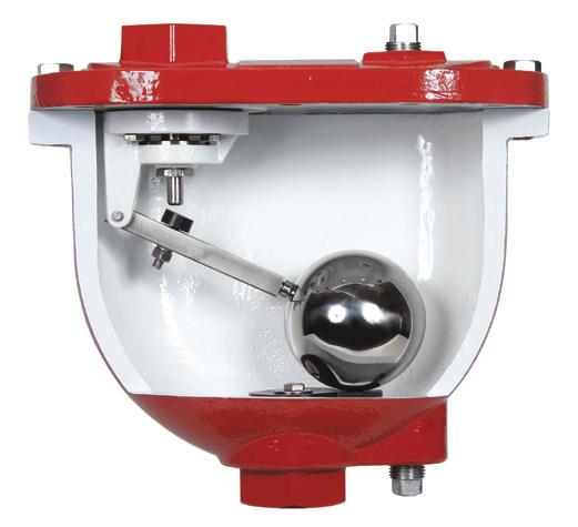
6 Series WAR Water Air Release s Introduction All 316 Stainless Steel Trim Standard All 316 Stainless Steel Floats Standard Ductile Iron Bodies and Covers Standard Vent Caps with Screens Included Upon Request Meets or Exceeds ANSI/AWWA C512 Standard/ NSF61/372 Certified Drop Tight Shut-off at Low Pressures AirPro Max Series WAR Air Release s are designed to vent trapped air that collects at high points in a pipeline. These valves continuously release air from systems thereby preventing large air pockets to form which can cause damaging pressure surge to the system. In many installations lacking Air Release s, large pockets of air in the pipeline will cause power consumption to increase, and flow to decrease, possibly completely. Another possible result of excessive air accumulation is the inexplicable pipeline rupture that is mistakenly attributed to ground settling or defective pipe. In reality unusually large air pockets can greatly increase the pressure of normally occurring surges to the point where sudden stops and starts of flow can cause a pipe to rupture. As air accumulates in the air valve, water is displaced, causing the stainless steel float to drop to a point where the valve orifice opens and the accumulated air is exhausted into the atmosphere. The water level in the air valve then rises and closes the valve orifice once again. This cycle repeats as needed and avoids the formation of potentially destructive air pockets. Scope of Line s 1/2", 3/4", 1", 2", 3" NPT; 6" #125 Flg. Pressure Ratings (See Note) 150 psi 175 psi 300 psi Note: Specify when operating pressure will be below 10 psi Temperature Range Water to 180 F Standard Materials Body and Cover: Ductile Iron ASTM A Float: 316 Stainless Steel Internal Trim: 316 Stainless Steel Orifice Button: Buna-N (EPDM available) External Cover Bolts: ASTM F SS Coating: 2-Part Liquid Epoxy (Fusion Bonded Epoxy available) Installation Series WAR AirPro Max Air Release s must be installed at high points in pipelines, and also at regular intervals (approximately every 1/4 to 1/2 mile) along uniform grade lines. Air s should be mounted in the vertical position at high points of the pipe, with an isolation valve installed below each valve in the event servicing is required. A valve vault with adequate air venting and drainage is recommended. Air Release Specification The Air Release shall be float operated, simple lever or compound lever type, designed to automatically vent accumulated air from the pipeline while the system is pressurized and operating. An adjustable designed orifice button shall be used to seal the valve discharge port with drip-tight shut-off. The diameter of the orifice must be sized to vent air within a given operating pressure range to insure maximum air venting capacity. The float and connection shall be all 316 stainless steel construction and guaranteed to withstand the designed system surge pressure without failure. The body and cover shall be ductile iron construction and valve internal parts and cover bolts shall be 316 stainless steel. The rubber orifice button shall be Buna-N for water tight shut-off. A vent cap with screen must be provided to prevent debris from entering the valve. The Air Release shall be manufactured per ANSI/ AWWA C512 and shall be Series WAR AirPro Max Air Release s manufactured by the Henry Pratt Company, Aurora, IL USA. 4 Henry Pratt Company
7 Series WAR Air Release s Simple Lever Orifice Max C.W.P. Inlet Connection W H HC Pratt Model # Wt. (Lbs.) Air Rel Code 1/2"* 1/16" 175 NPT 4-3/4" 5-1/4" 6-1/8" WAR A 3/4"* 1/16" 175 NPT 4-3/4" 5-1/4" 6-1/8" WAR B 1"* 1/16" 175 NPT 4-3/4" 5-1/4" 6-1/8" WAR C 1/2"* 3/32" 175 NPT 5-1/8" 6" 6-7/8" WAR D 3/4"* 3/32" 175 NPT 5-1/8" 6" 6-7/8" WAR E 1" 3/32" 175 NPT 5-1/8" 6" 6-7/8" WAR F 1/2"* 1/16" 300 NPT 5-1/8" 6" 6-7/8" WAR G 3/4"* 1/16" 300 NPT 5-1/8" 6" 6-7/8" WAR H 1" 1/16" 300 NPT 5-1/8" 6" 6-7/8" WAR I 3/4"* 1/8" 150 NPT 6-1/8" 7" 7-7/8" WAR J 3/4"* 3/32" 300 NPT 6-1/8" 7" 7-7/8" WAR K 1" 1/8" 150 NPT 6-1/8" 7" 7-7/8" WAR L 1" 3/32" 300 NPT 6-1/8" 7" 7-7/8" WAR M * = Reducer Bushing Included (1/2" NPT) /INLET Part # Description Material 1 Body ASTM A Cover ASTM A Lever Bracket ASTM A SS 4 Seat ASTM A SS 5 Float ASTM A SS 6 Gasket Non-Asbestos Fiber 7 Cover Bolt ASTM F SS 8 Lever Arm ASTM A SS 9 Button Buna-N (EPDM available) 10 Pivot Pin & Retaining Ring Stainless Steel 11 Float Retainer ASTM F SS 12 Positioner ASTM F SS 13 Lock Washer ASTM A SS 14 Pipe Plug Steel (316 SS available) 15 Reducer Bushing (*if required) ASTM A SS 16 Vent Cap and Screen ASTM A (Screen 316SS) Henry Pratt Company 5
8 Series WAR Air Release s Compound Lever Orifice Max C.W.P. Inlet Connection W H HC Pratt Model # Wt. (Lbs.) 1" 3/16" 150 NPT 7" 9-15/16" 10-13/16" WAR N 1" 5/32" 300 NPT 7" 9-15/16" 10-13/16" WAR O 2" 3/16" 150 NPT 7" 9-15/16" 10-13/16" WAR P 2" 5/32" 300 NPT 7" 9-15/16" 10-13/16" WAR Q 2" 23/64" 150 NPT 9-1/2" 12-1/4" 13-11/32" WAR R 2" 7/32" 300 NPT 9-1/2" 12-1/4" 13-11/32" WAR S 3" 23/64" 150 NPT 9-1/2" 12-1/4" 13-11/32" WAR T 3" 7/32" 300 NPT 9-1/2" 12-1/4" 13-11/32" WAR U Air Rel Code (1/2" 23.2 LB VALVE /1" 48.1 LB VALVE) /INLET Part # Description Material 1 Body ASTM A Cover ASTM A Lever Bracket ASTM A SS 4 Seat ASTM A SS 5 Float ASTM A SS 6 Gasket Non-Asbestos Fiber 7 Cover Bolt ASTM F SS 8 Short Lever Arm ASTM A SS 9 Button Stainless Steel & Buna-N (EPDM available) 10 Pivot Pin & Retaining Ring Stainless Steel 11 Float Retainer ASTM F SS 12 Positioner ASTM F SS 13 Lock Washer ASTM A SS 14 Lock Nut ASTM F SS 15 Pipe Plug Steel (316 SS Available) 16 Long Lever Arm ASTM A SS 17 Arm Link ASTM A SS 18 Positioning Pin 420SS 19 Lock Washer ASTM A SS 20 Clevis ASTM A SS 21 Vent Cap and Screen ASTM A (Screen 316 SS) 6 Henry Pratt Company
9 Series WAR Air Release s Compound Lever Orifice Max Inlet Wt. Air Rel C.W.P. Connection W H HC Pratt Model # (Lbs.) Code 6" 1" 150 #125 Flg 19-3/4" 22" 23-1/4" WAR V OUTLET SIZE (1" NPT) /INLET Part # Description Material 1 Body ASTM A Cover ASTM A Lever Bracket ASTM A SS 4 Seat ASTM A SS 5 Float ASTM A SS 6 Gasket Non-Asbestos Fiber 7 Cover Bolt ASTM F SS 8 Short Lever Arm ASTM A SS 9 Button Stainless Steel & Buna-N (EPDM available) 10 Pivot Pin & Retaining Ring Stainless Steel 11 Float Retainer ASTM F SS 12 Positioner ASTM F SS 13 Lock Washer ASTM A SS 14 Lock Nut ASTM F SS 15 Pipe Plug Steel 16 Long Lever Arm ASTM A SS 17 Arm Link ASTM A SS 18 Lever Bracket Base ASTM A SS 19 Cushion Buna-N (EPDM Available) 20 Cushion Retainer ASTM F SS 21 Pipe Plug Steel (316SS Available) 22 Vent Cap and Screen ASTM A (Screen 316 SS) Henry Pratt Company 7
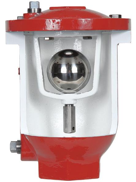
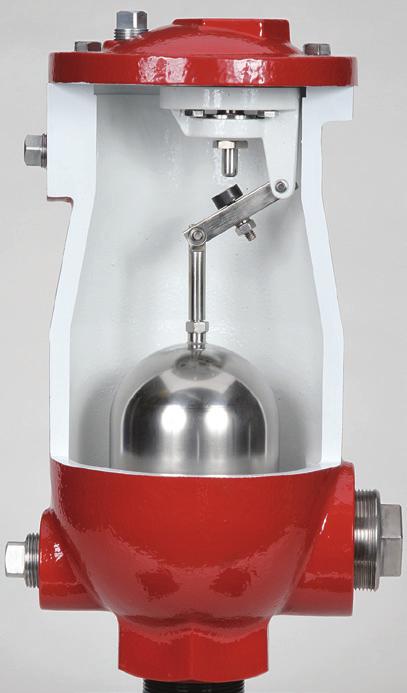
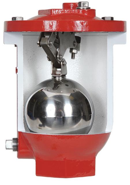
10 Series WAV Water Air Vacuum s Introduction Diffuser Standard for 1"-3" WAV s All 316 Stainless Steel Trim Standard All 316 Stainless Steel Floats Standard Ductile Iron Bodies and Covers Standard Threaded or Flanged Outlet with Screened Vent Cap or Hood Included Upon Request 1 Meets or Exceeds ANSI/AWWA C512 Standard/NSF61/372 Certified Optional Well Service Features Available AirPro Max Series WAV Air Vacuum s are high capacity air venting and intake valves designed to provide two separate functions. First, as the line is being filled with water they allow large quantities of air to be vented from the pipeline. When air has been completely vented, water enters the valve causing the stainless steel float to rise and seal tightly against the seat to prevent leakage. Second, when the line is drained, either intentionally or as a result of power failure or pipeline breakage, the air vacuum valve responds to a negative pressure and opens, allowing air to re-enter the valve and line preventing a vacuum from forming which could lead to damaging the pipeline. Series WAV Air Vacuum s do not open when closed and pressurized to exhaust any air that collects at high points during operation of the system. Series WAR Air Release s are needed for this function. Series WAV Air Vacuum valves 1"-3" are fitted with internal diffusers. Throttling devices are available for valves sized ½ 8. Please specify these options when ordering. Note: For valve sizing, see page 2. Scope of Line s 1/2", 1", 2", 3" NPT 4" through 24" 125 lb or 250 lb ANSI Flanged Pressure Ratings (See Note) 150 psi 300 psi Note: Specify when operating pressure will be below 10 psi Temperature Range Water to 180 F 1. Rain hoods and vent cap heights provided in our envelope dimensions are for typical applications where a low profile and typical 1/4" screen mesh is desired. If a special screen mesh or minimum vent flow capacity is needed, contact factory. Standard Materials Body and Cover: Ductile Iron ASTM A Float: 316 Stainless Steel Internal Trim: 316 Stainless Steel Seat: Buna-N (EPDM available) External Cover Bolts: ASTM F SS Coating: 2-Part Liquid Epoxy (Fusion Bonded Epoxy available) Installation Series WAV AirPro Max Air Vacuum s should be installed at pipeline high points, grade changes and regular intervals of approximately every 1/4 to 1/2 mile along uniform grade line of the pipeline. Mount each valve vertically on top of the pipe with an isolation valve below each valve in the event servicing is required. A vault with adequate venting and drainage should be provided. Air Vacuum Specifications Air Vacuum valve shall allow large volumes of air to be exhausted from the pipeline during filling and large volumes of air to re-enter when draining the pipeline occurs for any reason. The outlet size of the Air Vacuum shall have the same cross-section area as the valve inlet size. A stainless steel single bottom guide shaft shall guide the float. The 4" and larger air vacuum valve floats shall have top and bottom guide shafts to accurately guide the float, without hunting, into the seat for shut-off. A steel valve hood shall be provided to protect the valve discharge orifice from debris. The float shall be of all stainless steel construction guaranteed to withstand the design system surge pressure without failure. The body and cover shall be concentrically located for vertical float rising accurately into the seat shut-off position to prevent water spilling. The valve body and cover shall be constructed of ductile iron and the valve internal parts shall be of 316 Stainless Steel with Buna-N rubber seat. The Air Vacuum shall be manufactured per ANSI/ AWWA C512 and shall be Series WAV AirPro Max Air Vacuum s manufactured by the Henry Pratt Company, Aurora, IL USA. When Ordering, Please Specify: 1. Model Number 2. Inlet - NPT or Flanged 3. Inlet Pressure Rating 4. Specify when operating pressure will be below 10 psi. 8 Henry Pratt Company
11 Series WAV Air Vacuum Max Inlet Wt. C.W.P. Connection W H HC Pratt Model # (Lbs.) 1/2" 300 NPT 6-1/8" 7" 7-7/8" WAR (1/2" NPT) /INLET Part # Description Material 1 Body ASTM A Cover ASTM A Baffle ASTM A Seat Buna-N (EPDM available) 5 Float ASTM A SS 6 Gasket Non-Asbestos Fiber 7 Cover Bolt ASTM F SS 8 Baffle Bracket ASTM F SS 9 Guide Bushing ASTM A SS 10 Guide Shaft ASTM A SS 11 Pipe Plug Steel (316 SS Available) 12 Vent Cap and Screen ASTM A (Screen 316SS) Optional Diffuser ASTM A SS Optional Throttling Device ASTM A Henry Pratt Company 9
12 Series WAV Air Vacuum Max C.W.P. Inlet Connection W H HC Pratt Model # Wt. (Lbs.) 1" 300 NPT 7" 9-1/2"" 10-5/8" WAV FS " 300 NPT 9-1/2" 11-15/16" 13-13/16" WAV FS " 300 NPT 9-1/2" 12" 14-5/8" WAV FS 50.4 (SAME AS INLET) VALVE SIZE/INLET Part # Description Material 1 Body ASTM A Cover ASTM A Baffle ASTM A Seat EPDM 5 Float ASTM A SS 6 Gasket Non-Asbestos Fiber 7 Cover Bolt ASTM F SS 8 Baffle Bracket ASTM F SS 9 Guide Bushing ASTM A SS 10 Washer ASTM A SS 11 Pipe Plug 316 Stainless Steel 12 Vent Cap and Screen ASTM A (Screen 316SS) 13 Diffuser ASTM A SS Optional Throttling Device ASTM A Henry Pratt Company
13 Series WAV Air Vacuum Max C.W.P. Inlet Connection W H HC Pratt Model # Wt. (Lbs.) 4" 150 #125 Flg 12" 15-3/4" 16-7/8" WAV F-FS 104 4" 300 #125 Flg 12" 15-3/4" 16-7/8" WAV F-FS 104 (4" THREADED OUTLET) /INLET Part # Description Material 1 Body ASTM A Cover ASTM A Guide Bushing ASTM A SS 4 Seat Buna-N (EPDM available) 5 Float ASTM A SS 6 O-Ring Buna-N (EPDM available) 7 Cover Bolt ASTM F SS 8 Shoulder Screw ASTM F SS 9 Cushion Bumper Buna-N (EPDM available) 10 Washer 316SS 11 Pipe Plug 316SS 12 Hood and Screen Steel (Screen 316 SS) 13 Hood Bolt Steel Henry Pratt Company 11
14 Series WAV Air Vacuum Max C.W.P. Inlet Connection W H HC Pratt Model # Wt. (Lbs.) 6" 150 #125 Flg 14" 18-9/16" 20-5/16" WAV F 158 6" 300 #250 Flg 14" 18-9/16" 20-5/16" WAV F 158 (6" NPT) /INLET Part # Description Material 1 Body ASTM A Cover ASTM A Bushing ASTM A SS 4 Seat Buna-N (EPDM available) 5 Float ASTM A SS 6 O-Ring Buna-N (EPDM available) 7 Cover Bolt ASTM F SS 8 Shoulder Screw ASTM F SS 9 Cushion Bumper Buna-N (EPDM available) 10 Washer 316SS 11 Pipe Plug 316SS 12 Hood Steel 13 Hood Bolt Steel 14 Screen Steel 12 Henry Pratt Company
15 Series WAV Air Vacuum Max C.W.P. Inlet Connection W H HC Pratt Model # Wt. (Lbs.) 8" 150 #125 Flg 18" 21-9/16" 23-9/16" WAV F 284 8" 300 #250 Flg 18" 21-9/16" 23-9/16" WAV F 284 (8" NPT) /INLET Part # Description Material 1 Body ASTM A Cover ASTM A Guide Bushing ASTM A SS 4 Seat Buna-N (EPDM available) 5 Float ASTM A SS 6 O-Ring Buna-N (EPDM available) 7 Cover Bolt ASTM F SS 8 Shoulder Screw ASTM F SS 9 Cushion Bumper Buna-N (EPDM available) 10 Washer 316SS 11 Pipe Plug Steel (316SS available) 12 Hood Steel 13 Hood Bolt Steel 14 Screen Steel Henry Pratt Company 13
16 Series WAV Air Vacuum Max C.W.P. Inlet Connection W H HC Pratt Model # Wt. (Lbs.) 10" 150 #125 Flg 20" 26" 31" WAV F " 300 #250 Flg 20" 26" 31" WAV F " 150 #125 Flg 24" 30" 35" WAV F " 300 #250 Flg 24" 30" 35" WAV F " 150 #125 Flg 27" 32" 38" WAV F " 300 #250 Flg 27" 32" 38" WAV F " 150 #125 Flg 30-1/2" 34" 41" WAV F " 300 #250 Flg 30-1/2" 34" 41" WAV F " 150 #125 Flg 38-1/4" 42" 51" WAV F " 300 #250 Flg 38-1/4" 42" 51" WAV F " 150 #125 Flg 44" 50" 59" WAV F-FS " 300 #250 Flg 44" 50" 59" WAV F-FS 3053 (SAME AS INLET/#125 FLANGE) /INLET Part # Description Material 1 Body ASTM A Cover ASTM A Guide Bushing ASTM A SS 4 Seat Buna-N (EPDM available) 5 Float ASTM A SS 6 O-Ring Buna-N (EPDM available) 7 Cover Bolt ASTM F SS 8 Shoulder Screw ASTM F SS 9 Cushion Bumper Buna-N (EPDM available) 10 Washer 316SS 11 Pipe Plug Steel (316SS available) 12 Hood Steel 13 Hood Bolt Steel 14 Screen Steel 14 Henry Pratt Company
17 Series WAV-D Water Air/Vacuum (Deep-well Service) Provides for Deep Well Pump Flow Optimization Well service pumps start up with low water level and a long column of air which results in little or no head (backpressure) while the pump fills the casing. At pump start, conditions may exist which allow water flow to exceed 10 feet per second as it moves up with little resistance inside a well casing while air is being discharged from the line. Since a fast water column is rising immediately following the escaping air column, it is critical to protect the float from the in-rushing water column. If the float is not shielded the fast moving water column will strike the float and slam it shut prematurely, sometimes closing the valve prematurely before all air escapes. There are various means to protect the air valve float and system. Each device is ranked in order of increasing degree of protection: Diffuser (perforated basket which aerates and moderates water flow) Anti-Shock Slow Closing Surge Check Air (perforated disc sprung open to allow slow fill of float chamber) Double-Acting Throttling Device (device which controls outflowing air backpressure with variable plug closure- but allows free air in) Positive control of the water flow is provided by a Diffuser a float-enclosing, perforated basket which will aerate and disperse a fast straight-on column impact into steady, slower flow. Water is forced through the perforations and aerated as it streams through to buoy up the float in a controlled manner. The Pratt throttling device is the final level of protection that can be provided for deep well service pump/ pipeline systems. This proven design is the maximum protection that can be provided for slowing down the water column. Well Service Air General Specification For a CSI formatted specification describing the AirPro Max Well Service s, please contact your local sales representative. CWP AØ B C NPT D NPT E F G Part # Wt. 1" 300 7" 12-1/8" 1" 1" 1-1/2" 7/8 3-5/8 WAV10-300D-FS 25 2" /2" 15-15/16" 2" 2" 2-1/4" 1-1/2 5-3/4 WAV20-300D-FS 54 3" /2" 16-7/16"" 3" 3" 3-1/16" 2-1/8 7-11/16 WAV30-300D-FS 55 Item # Description Material 1 Body Ductile Iron 2 Cover Ductile Iron 3 Baffle Ductile Iron 4 Seat EPDM 5 Float ASTM A SS 6 Gasket Non-Asbestos Fiber 7 Cover Bolts ASTM F SS 8 Baffle Bracket Bolts ASTM F SS 9 Guide Bushing ASTM A SS 10 Guide Shaft ASTM A SS 11 Pipe Plug 316SS 12 Diffuser Perforated 316SS 13 Pipe Nipple Carbon Steel 14 Tee Pipe Fitting Cast Iron 15 Plug Cast Iron ASTM A Bolt ASTM A SS 17 Throttle Disc ASTM A SS 18a Spring ASTM A SS 18b Antishock Spring ASTM A SS (Optional) 19 Flat Washer ASTM A SS 20 Hex Lock Nut Nylon Insert Steel Nut All well service valves should be piped to drain or back to well to muffle sound of escaping air. No screen is provided. Henry Pratt Company 15
18 Anti-Shock Air Vacuum s Series WAVASD and WAVAS Pratt AirPro Max Anti-Shock Air s are equipped with a slow closing action which regulates the flow of water into a valve float chamber. This regulation of flow provides additional protection by preventing the air valve float from slamming shut during critical operations. This controlled closure of the air valve prevents surge or water hammer conditions from occurring and helps eliminate the possibility of damage to the valve caused by excessive pressure forces. The Series WAVAS Anti-Shock Air, mounted on the inlet of the air valve, is a normally open valve. The disc is held open by a flexible spring allowing air to pass through unrestricted. As the Anti-Shock fills with water the disc quickly closes preventing fluid surge into the air valve. The disc of the Anti-Shock is drilled with adjustable flow ports which allow water to only enter the Air Vacuum at a measured rate. This regulated flow closes the Air Vacuum without excessive force caused by surge or water hammer. When the Air Vacuum is closed the pressure on both sides of the Anti-Shock Check disc equalize, returning the disc to the open position. This allows the Air Vacuum to open at any time the water level drops and line pressure approaches atmospheric, permitting air to re-enter the pipeline before a vacuum can form. Series WAVAS Anti-Shock Air s should be used: At high points in pipelines where the hydraulic gradient and flow conditions are such that a negative pressure can possibly form. High points on sections of the pipeline having velocities in excess of 7-10 f/s. Adjacent to any quick closing valve in a pipeline where a vacuum can be formed when closed. On the discharge of larger deep well turbine pumps, between the pump and the check valve. Anti-Shock Air Assembly Drawing Air Vacuum Anti-Shock Combo # Model Part # A B CWP** 2" WAVASD WAV FS* WAVAS /8" 9-1/2" 150 3" WAVASD WAV FS* WAVAS /16" 9-1/2" 150 4" WAVASD WAV40-150F WAVAS /4" 12" 150 6" WAVASD WAV60-150F WAVAS /2" 14" 150 8" WAVASD WAV80-150F WAVAS /8" 18" " WAVASD WAV F WAVAS /8" 20" " WAVASD WAV F WAVAS /8" 24" " WAVASD WAV F WAVAS /8" 27" " WAVASD WAV F WAVAS /4" 30-1/2" " WAVASD WAV F WAVAS " 38-1/4" 150 *Threaded inlet with flange adapter **300 CWP available, contact factory for information Part # Description Material 1 Body ASTM A Disc ASTM A Spring 304SS 4 Bushing 304SS 5 Seat 304SS 6 Screw Steel 7 Gasket EPDM For WAV drawing details, reference WAV series Water Air Vacuum s (Pages 12-16). 16 Henry Pratt Company
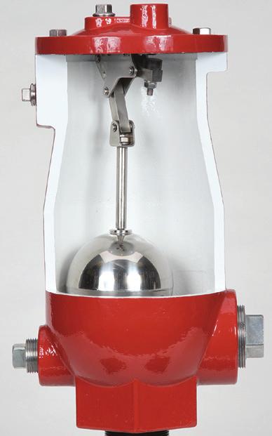
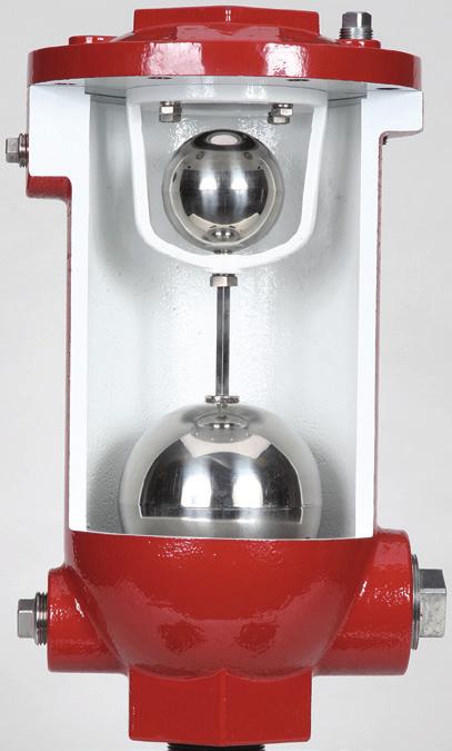
19 Series WCV Combination Air s Introduction All 316 Stainless Steel Trim Standard All 316 Stainless Steel Floats Standard Threaded Outlet with Screened Vent Cap or Rain HoodIncluded as Standard Meets or Exceeds ANSI/AWWA C512 Standard/ NSF61/372 Certified Drop Tight Shut-off At Low Pressures The AirPro Max Series WCV Combination Air combines the functions of both the Air Release and Air Vacuum. Our Series WCV Combination allows a large volume of air to be vented when filling, or a large volume of air intake when draining the pipeline. The Combination Air also vents small pockets of air that accumulate after the line is filled, pressurized and operating. Series WCV Combination Air s are offered in both single body and dual body designs. Note: For valve sizing, see page 2. Scope of Line s Single Body Design 1", 2", 3", 4 NPT 3 through 8 Flanged ANSI Class 125 & 250 Dual Body Design 1", 2", 3" NPT 4" through 16" Flanged ANSI Class 125 & 250 Pressure Ratings (See Note) 150 psi 300 psi Note: Specify when operating pressure will be below 10 psi Temperature Range Water to 180 F Installation Series WCV AirPro Max Combination Air s should be installed at high points and change of gradients and regular intervals of approximately every 1/4 to 1/2 miles along lines without clearly defined high points. Install valves vertically on top of the pipeline with an isolation valve under each valve should servicing be required. A vault with adequate venting and drainage is highly recommended. Suggested Specifications The Combination Air shall function as an air vacuum valve and air release valve in a single or dual body design. The large air vacuum orifice shall allow large volumes of air to be exhausted during pipeline filling and large volume of air intake while draining, or in the event of a break in the pipeline, to prevent a vacuum from forming. The inlet/outlet and seat of the valve shall have the same flow area. The stainless steel poppet shall be guided by a stainless steel guide shaft and seal drip tight against a Buna-N seat. 4" and larger valves shall have dual guided stainless steel shafts of hexagonal cross section and a protective discharge hood. The float shall be of all stainless steel construction and capable of withstanding maximum system surge pressure without failure. The body and cover shall be concentrically located and of ductile iron and the valve internal trim shall be of 316 Stainless Steel. Seat shall be Buna-N for water tight shut off. The Combination Air shall be manufactured per ANSI/AWWA C512 and shall be Series WCV AirPro Max Combination Air s manufactured by the Henry Pratt Company, Aurora, IL USA. When Ordering, Please Specify 1. Model Number 2. Inlet/Outlet & Connection 3. Pressure Rating Standard Materials Body and Cover: Ductile Iron ASTM A Float: 316 Stainless Steel Internal Trim: 316 Stainless Steel Seat: Buna-N (EPDM available) External Cover Bolts: ASTM F SS Coating: 2-Part Liquid Epoxy (Fusion Bonded Epoxy available) Henry Pratt Company 17
20 Series WCV Combination Air s Orifice Max C.W.P. Inlet Connection W H HC Pratt Model # Wt. (Lbs.) 1" 5/64" 300 NPT 11-3/8" 10-1/2" 11-5/8" WCV FS " 3/32" 300 NPT 14" 13" 14-7/8" WCV FS " 3/32" 300 NPT 16" 15" 17-9/16" WCV FS 114 3" 3/32" 150 #125 Flg 16" 17" 19-9/16" WCV F 114 3" 3/32" 300 #250 Flg 16" 17-1/2" 20-1/16" WCV F 114 4" 3/32" 300 NPT 18-1/2" 17" 20" WCV " 3/32" 150 #125 Flg 18-1/2" 19" 22" WCV F " 3/32" 300 #250 Flg 18-1/2" 19-1/2" 22-1/2" WCV F (SAME AS INLET) VALVE SIZE/INLET Part # Description Material 1 Body ASTM A Cover ASTM A Lever Frame ASTM A Seat Buna-N (EPDM available) 5 Float ASTM A SS 6 Gasket Non-Asbestos Fiber 7 Cover Bolt ASTM F SS 8 Lever Arm ASTM F SS 9 Button Stainless Steel & Buna-N 10 Pivot Pin & Retaining Ring 316SS 11 Cushion Retainer ASTM F SS 12 Lever Frame Bracket ASTM F SS 13 Lock Washer ASTM A SS 14 Lock Nut ASTM F SS 15 Pipe Plug Steel (316SS available) 16 Poppet ASTM A SS 17 Guide Bushing ASTM A SS 18 Cushion Buna-N (EPDM available) 19 Washer ASTM A SS 20 Vent Cap ASTM A Henry Pratt Company
21 Series WCV Combination Air s Orifice Max C.W.P. Inlet Connection W H HC Pratt Model # Wt. (Lbs.) 6" 6" 150 #125 Flg 21" 18-3/4" 20-1/2" WCV F 231 6" 6" 300 #250 Flg 21" 18-3/4" 20-1/2" WCV F 231 8" 8" 150 #125 Flg 25" 21-11/16" 23-11/16" WCV F 373 8" 8" 300 #250 Flg 25" 21-11/16" 23-11/16" WCV F 373 (SAME AS INLET) /INLET Part # Description Material 1 Body ASTM A Cover ASTM A Bushing ASTM A SS 4 Seat Buna-N (EPDM available) 5 Float ASTM A SS 6 Gasket ASTM A Cover Bolt ASTM F SS 8 Shoulder Screw ASTM F SS 9 Cushion Bumper Buna-N (EPDM available) 10 Washer ASTM A SS 11 Float Retainer ASTM F SS 12 Lock Washer ASTM A SS 13 Lock Washer ASTM A SS 14 Lock Nut ASTM F SS 15 Float ASTM A SS 16 Long Lever Arm ASTM A SS 17 Arm Link ASTM A SS 18 Short Lever Arm ASTM A SS 19 Button 316SS & Buna-N 20 Pivot Pin & Retaining Ring 316SS Stainless Steel 21 Positioning Pin 420SS 22 Positioner ASTM F SS 23 Lever Bracket ASTM A SS 24 Seat ASTM A SS 25 Pipe Plug Steel (316SS available) 26 Hood Steel 27 Hood Bolt Steel 28 Screen Steel 29 Vent Cap ASTM A Henry Pratt Company 19
22 Series WCVD Combination Air s (Dual Body) Orifice Max C.W.P. Inlet Connection Air Vacuum Air Release A B Wt. (Lbs) Pratt Model # 1" 1/16" 300 psi NPT WAV WAR " 17" 33 WCVD " 1/16" 300 psi NPT WAV WAR /2" 19" 60 WCVD " 1/16" 300 psi NPT WAV WAR /2" 19" 62 WCVD /INLET No. Part Name/Drawing No. Specs. 1 Air Vacuum See Series WAV 2 Air Release See Series WAR 3 Dual Body Pipe Nipple (Shipped separately for field install by others) Galvanized Steel Pipe 20 Henry Pratt Company
23 Series WCVD Combination Air s (Dual Body) Orifice Max C.W.P. Inlet Connection Air Vacuum Air Release A B Wt. (Lbs) Pratt Model # 4" 3/16" 150 psi 125# Flg WAV40-150F WAR " 22-1/2" 131 WCVD " 5/32" 300 psi 250# Flg WAV40-300F WAR " 22-1/2" 139 WCVD /INLET No. Part Name/Drawing No. Specs. 1 Air Vacuum See Series WAV 2 Air Release See Series WAR 3 Dual Body Pipe Nipple (Shipped separately for field install by others) Galvanized Steel Pipe & SS Ball Henry Pratt Company 21
24 Series WCVD Combination Air s (Dual Body) Orifice Max C.W.P. Inlet Connection Air Vacuum Air Release Bypass A B Wt. (Lbs) Pratt Model # 6" 3/16" 150 psi 150# Flg WAV60-150F WAR " 22" 24-1/4" 187 WCVD " 5/32" 300 psi 300# Flg WAV60-300F WAR " 22" 24-1/4" 217 WCVD " 3/16" 150 psi 150# Flg WAV80-150F WAR " 26" 25-1/2" 316 WCVD " 5/32" 300 psi 300# Flg WAV80-300F WAR " 26" 25-1/2" 346 WCVD " 23/64" 150 psi 150# Flg WAV80-150F WAR " 30" 29" 344 WCVD " 7/32" 300 psi 300# Flg WAV80-300F WAR " 30" 29" 374 WCVD /INLET No. Part Name/Drawing No. Specs. 1 Air Vacuum See Series WAV 2 Air Release See Series WAR 3 Dual Body Pipe Nipple (Shipped separately for field install by others) Galvanized Steel Pipe & SS Ball 22 Henry Pratt Company
25 Series WCVD Combination Air s (Dual Body) Orifice Max C.W.P. Inlet Connection Air Vacuum Air Release A B Wt. (Lbs) Pratt Model # 10" 3/16" 150 psi 150# Flg WAV F WAR " 31" 465 WCVD " 5/32" 300 psi 300# Flg WAV F WAR " 31" 490 WCVD " 23/64" 150 psi 150# Flg WAV F WAR " 32-1/2" 495 WCVD " 7/32" 300 psi 300# Flg WAV F WAR " 32-1/2" 520 WCVD " 3/16" 150 psi 150# Flg WAV F WAR " 35" 715 WCVD " 5/32" 300 psi 300# Flg WAV F WAR " 35" 740 WCVD " 23/64" 150 psi 150# Flg WAV F WAR " 36" 745 WCVD " 7/32" 300 psi 300# Flg WAV F WAR " 36" 765 WCVD " 3/16" 150 psi 150# Flg WAV F WAR " 38" 950 WCVD " 5/32" 300 psi 300# Flg WAV F WAR " 38" 975 WCVD " 23/64" 150 psi 150# Flg WAV F WAR " 38" 975 WCVD " 7/32" 300 psi 300# Flg WAV F WAR " 38" 1000 WCVD " 3/16" 150 psi 150# Flg WAV F WAR /2" 41" 1280 WCVD " 5/32" 300 psi 300# Flg WAV F WAR /2" 41" 1300 WCVD " 23/64" 150 psi 150# Flg WAV F WAR /2" 41" 1310 WCVD " 7/32" 300 psi 300# Flg WAV F WAR /2" 41" 1330 WCVD /INLET No. Part Name/Drawing No. Specs. 1 Air Vacuum See Series WAV 2 Air Release See Series WAR 3 Dual Body Piping Kit (Shipped separately for field install by others) Galvanized Steel Pipe & SS Ball Henry Pratt Company 23
26 Series WAVVB Vacuum Breaker Air Inlet Pratt AirPro Max Vacuum Breaker s (Series WAVVB) are designed as large orifice, one way, spring loaded valves that allow air flow in only one direction (air flowing in to the pipeline). All standard valves begin admitting air at a minimal ¼ - ½ PSI vacuum to maximize vacuum breaking potential. When the vacuum condition ceases, the vacuum breaker valve disc is instantly closed against the body seat, thereby trapping air at the high point. The fast closure of the valve disc avoids any slamming which could be caused when the water column rejoins. By equipping the Vacuum Breaker with an optional AirPro Max Series WAR Air Release valve as a special combination setup, the assembly acts as a free air in controlled air out regulator. After a vacuum condition ceases and the line returns to positive pressure the Air Release valve slowly releases the trapped air and bleeds it to atmosphere. In this manner, the pipeline is fully restored in a controlled manner to normal operating condition (pipeline fully charged with liquid media). Series WAVVB Vacuum Breaker s should be used: For high vacuum break capacity required to protect critical infrastructure (like a penstock, etc.) At high points in pipelines where the hydraulic gradient and flow conditions are such that a negative pressure can possibly form but where some trapped air is desired for cushioning (until bled off). Where water column separation is expected which may result in water hammer. Adjacent to any quick closing valve in a pipeline where a severe vacuum can be formed when closed. Vacuum Breaker Vacuum Breaker Model Air Release Model A B2 C Combo Model # 3" WAVVB-30 WAR " 16-1/8" 7-1/2" WAVVBD " WAVVB-40 WAR /4" 17-3/4" 9" WAVVBD " WAVVB-60 WAR /2" 20-3/8" 12-1/2" WAVVBD " WAVVB-80 WAR " 25-3/8" 16-1/4" WAVVBD " WAVVB-100 WAR " 27-1/8" 16" WAVVBD " WAVVB-120 WAR /4" 28-3/8" 19" WAVVBD " WAVVB-140 WAR /4" 31-3/4" 21" WAVVBD " WAVVB-160 WAR /8" 35-1/4" 23-1/2" WAVVBD " WAVVB-180 WAR /4" 38-1/4" 25" WAVVBD " WAVVB-200 WAR /8" 42" 27-1/2" WAVVBD *250# Flange Available Vacuum Breaker 1 Body Ductile 2 Seat 304 Stainless Steel/EPDM 3 Gasket EPDM 4 Disc 304 Stainless Steel 5 Spring 304 Stainless Steel 6 Bushing 304 Stainless Steel 7 Gasket EPDM WAR Series Air Release shown as typical option. For other Air Release selection add air release code to base combo valve. 24 Henry Pratt Company
27 Series WWAR Wastewater Air Release s Introduction All 316 Stainless Steel Trim Standard All 316 Stainless Steel Floats Standard Ductile Iron Bodies and Covers Standard Service Without Removal from Pipeline Drop Tight Shut-off at Low Pressures Optional Backwash Kit Available AirPro Max Series WWAR Wastewater Air Release s are specifically designed for wastewater having an elongated valve body to prevent the collection of waste in the linkage area of the air valve. Series WWAR valves prevent disruption of service by venting pockets of air that collect at high points in a pipeline. These valves continuously eliminate air from systems by releasing small pockets of air before large air pockets can occur. In many installations lacking Air Release s accumulations of air in the pipeline will cause flow to decrease, and power consumption to increase, due to air blocks in the system. Another possible result of excessive air accumulation may be an inexplicable pipeline rupture. These ruptures are often falsely attributed to ground settling or defective pipe. In reality, unusually large air pockets can greatly increase the pressure of normally occurring surges to the point where sudden stops and starts of flow can cause a pipe collapse. As air accumulates at a high point in the pipeline, liquid is displaced within the air valve, lowering the water level, causing the stainless steel float to drop. When the float drops to a pre-determined point the valve orifice opens and permits accumulated air to be exhausted into the atmosphere. The liquid level in the air valve then rises and closes the valve orifice once again. This cycle repeats as needed and avoids the formation of potentially destructive air pockets. Scope of Line s 2", 3", 4" NPT Pressure Ratings (See Note) 75 psi 150 psi 300 psi Note: Specify when operating pressure will be below 10 psi Standard Materials Body and Cover: Ductile Iron ASTM A Float: 316 Stainless Steel Internal Trim: 316 Stainless Steel Seat: Buna-N External Cover Bolts: ASTM F SS Coating: 2-Part Liquid Epoxy Coated Interior and Exterior (Fusion Bonded Epoxy available) Installation Series WWAR AirPro Max Wastewater Air Release s should be installed at high points in pipelines and also at regular intervals (approximately every 1/4 to 1/2 mile) along uniform grade lines. s should be mounted in the vertical position on top of the pipe with an isolation valve installed below each valve in the event servicing is required. A vault with adequate air venting and drainage is recommended. An optional customer-installed Backwash Kit is available. This kit is used for regular cleaning to keep equipment in good working condition. It includes a back flushing hose and quick disconnect couplings. Wastewater Air Release Specifications The Air Release shall be of the float operated, compound lever type, and capable of automatically venting accumulated air, gas or vapor from a fluid system while the system is pressurized and operating. An adjustable designed orifice button shall be used to seal the valve discharge port with drip-tight shut-off. The diameter of the orifice must be sized for use within a given operating pressure range to insure maximum air venting capacity. The float shall be of all stainless steel construction and guaranteed to withstand the maximum system surge pressure without failure. The body and the cover shall be of ductile iron and all valve internal parts shall be of stainless steel. The rubber seat is Buna-N for water tight shut-off. The air release valve shall be manufactured per ANSI/ AWWA C512 and shall be Series WWAR AirPro Max Wastewater Air Release s manufactured by the Henry Pratt Company, Aurora, IL USA. Henry Pratt Company 25
 Air Rel Code 2\" 1/2\" 5/16\" 75 NPT 7\" 15-5/16\" WWAR202005-516-75 40 WA 2\" 1/2\" 3/16\" 150 NPT 7\" 15-5/16\" WWAR202005-316-150 40 WB 2\" 1/2\" 5/32\" 300 NPT 7\" 15-5/16\" WWAR202005-532-300 40 WC 2\" 1\"")
28 Series WWAR Wastewater Air Release s Outlet Orifice Max C.W.P. Inlet Connection W H Pratt Model # Wt. (Lbs) Air Rel Code 2" 1/2" 5/16" 75 NPT 7" 15-5/16" WWAR WA 2" 1/2" 3/16" 150 NPT 7" 15-5/16" WWAR WB 2" 1/2" 5/32" 300 NPT 7" 15-5/16" WWAR WC 2" 1" 1/2" 75 NPT 9-1/2" 17-9/16" WWAR WD 2" 1" 7/16" 150 NPT 9-1/2" 17-9/16" WWAR WE 2" 1" 7/32" 300 NPT 9-1/2" 17-9/16" WWAR WF 3" 1/2" 5/16" 75 NPT 7" 15-5/16" WWAR WG 3" 1/2" 3/16" 150 NPT 7" 15-5/16" WWAR WH 3" 1/2" 5/32" 300 NPT 7" 15-5/16" WWAR WI 3" 1" 1/2" 75 NPT 9-1/2" 17-9/16" WWAR WJ 3" 1" 7/16" 150 NPT 9-1/2" 17-9/16" WWAR WK 3" 1" 7/32" 300 NPT 9-1/2" 17-9/16" WWAR WL 4" 1/2" 5/16" 75 NPT 7" 15-5/16" WWAR WM 4" 1/2" 3/16" 150 NPT 7" 15-5/16" WWAR WN 4" 1/2" 5/32" 300 NPT 7" 15-5/16" WWAR WO 4" 1" 1/2" 75 NPT 9-1/2" 17-9/16" WWAR WP 4" 1" 7/16" 150 NPT 9-1/2" 17-9/16" WWAR WQ 4" 1" 7/32" 300 NPT 9-1/2" 17-9/16" WWAR WR Note: Please see next page for drawing and chart. 26 Henry Pratt Company
29 Series WWAR 01 Wastewater Air Release s VALVE SIZE/INLET Part # Description Material 1 Body ASTM A Cover ASTM A Lever Bracket ASTM A SS 4 Seat ASTM A SS 5 Float ASTM A SS 6 Gasket Non-Asbestos Fiber 7 Cover Bolt ASTM F SS 8 Short Lever Arm ASTM F SS 9 Button Stainless Steel & Buna-N 10 Pivot Pin & Retaining Ring 316SS 11 Float Retainer ASTM F SS 12 Positioner ASTM A SS 13 Lock Washer ASTM A SS 14 Lock Nut ASTM F SS 15 Pipe Plug Steel (316SS Available) 16 Long Lever Arm ASTM A SS 17 Arm Link ASTM A SS 18 Positioning Pin 420SS 19 Lock Washer ASTM A SS 20 Clevis ASTM A SS 21 Extension Shaft ASTM A SS 22 Socket Set Screw ASTM A SS 23 Pipe Plug Steel (316SS Available) 24 Pipe Plug Steel (316SS Available) Henry Pratt Company 27
30 Series WWAV Wastewater Air Vacuum s Introduction All 316 Stainless Steel Trim Standard All 316 Stainless Steel Floats Standard Fully Ported s - No Restrictions Drop Tight Shut-off At Low Pressures Optional Backwash Kit Available The AirPro Max Series WWAV Wastewater Air Vacuum s are specifically designed with elongated valve bodies. The purpose of the elongated bodies is to increase the gap between the float and the mechanical linkage inside and top of the valve body. The valve is designed to perform two critical functions. First, as the line is being filled with water they expel large quantities of air from the pipeline. When air has been completely vented, water enters the valve causing the float to seal tightly against the seat to prevent leakage. Second, when the line is drained, either intentionally or as a result of pipeline breakage, the Air Vacuum responds to the drop in pressure and opens. Air then re-enters the valve and line eliminating the conditions which could lead to a damaging vacuum developing in the pipeline. Air Vacuum s do not open when under pressure to exhaust small quantities of air that may collect at high points during operation of the system. A Series WWAR Air Release is required for this function. Scope of Line s 2" & 3" NPT 4, 6, 8 flanged ANSI Class 125 Pressure Rating (See Note) 150 psi Note: Specify when operating pressure will be below 10 psi Standard Materials Body and Cover: Ductile Iron ASTM A Float: 316 Stainless Steel Internal Trim: 316 Stainless Steel Seat: Buna-N External Cover Bolts: ASTM F SS Coating: 2-Part Liquid Epoxy Coated Interior and Exterior (Fusion Bonded Epoxy available) Installation Series WWAV AirPro Max Wastewater Air Vacuum s are typically installed at high points and at grade changes along the pipeline. Mount each unit vertically on top of the pipe with an isolation valve below each valve in the event servicing is required. A vault with adequate venting and drainage should be provided. An optional customer-installed Backwash Kit is available. This kit is used for regular cleaning to keep equipment in good working condition. It includes a back flushing hose and quick disconnect couplings. Wastewater Air Vacuum Specifications The Wastewater Air Vacuum shall be able to automatically exhaust large quantities of air during filling of a pipeline and allow air to re-enter pipeline during the draining or when a negative pressure occurs. The inlet and outlet of the Air Vacuum shall have the same cross-section area as the valve size. A stainless steel bottom guide shaft shall guide the float. The 4" and larger valve floats shall have top and bottom guide shafts of hexagonal cross section and have a protective steel discharge hood. The float shall be of all stainless steel construction and capable of withstanding maximum system surge pressure without failure. The body and cover shall be concentrically located and of ductile iron and the valve internal parts shall be of 316 stainless steel with Buna-N rubber seat. The Wastewater Air Vacuum shall be manufactured per ANSI/AWWA C512 and shall be Series WWAV AirPro Max Air Vacuum s manufactured by the Henry Pratt Company, Aurora, IL USA. When Ordering, Please Specify: 1. Model Number 2. Inlet 3. Optional Backwash Kit (See page 37) 28 Henry Pratt Company
AIRPRO MAX AIR VALVES. Engineering Creative Solutions for Fluid Systems Since 1901
 AIRPRO MAX AIR VALVES Engineering Creative Solutions for Fluid Systems Since 0 TABLE OF CONTENTS AIRPRO MAX AIR VALVES Air Release Valve Data and Sizing Guide... Air Vacuum Valve Data and Sizing Guide...-
Air Valves. Patent Pending. Engineering Creative Solutions for Fluid Systems Since 1901
 Air Valves Patent Pending Engineering Creative Solutions for Fluid Systems Since 1901 A Tradition of Excellence With the development of the first rubber seated butterfly valve more than 70 years ago, the
Series 34. Specifications
 Series Air Release Valves Stainless Steel T Trim Standard Stainless Steel Floats Guaranteed Easily Serviced Without Removal From Pipeline Working Pressures to 800 PSI Engineered For Drip Tight Seal At
D-023 PN 16 / 25. Combination Air Valve for Wastewater PATENTED. Description. Applications. Operation. Main Features
 PN 16 / 25 Wastewater Combination Air Valve for Wastewater PATENTED EuroC-D023SWG-15-2 Description The D-023 Combination Air Valve combines an air & vacuum component and an air release component in a single
CUSTOM COMBINATION AIR VALVE
 INSTALLATION / OPERATION / MAINTENANCE CUSTOM COMBINATION AIR VALVE INTRODUCTION This manual will provide you with the information to properly install and maintain this valve to ensure a long service life.
AIR/VACUUM VALVE AND OPTIONAL ANTI-SLAM DEVICE SPECIFICATION
 AIR/VACUUM AND OPTIONAL ANTI-SLAM DEVICE SPECIFICATION Scope. This specification is intended to cover the design, manufacture, and testing of / in. (3 mm) through 0 in. (00 mm) Air/Vacuum Valves suitable
US SERIES. Universal Sewer Valves. Universal Sewer Valves. Valve Function. Features Include
 Valve Function Exhausts air as a pipeline fills, and allows air in as pipeline drains Allows accumulating air to escape while line is in operation Features Include Standard and short body series available
The Universal Sewer Air Release Valve is designed to permit
 Universal Sewer Valves Universal Sewer Valves Valve Function Exhausts air as a pipeline fills, and allows air in as pipeline drains Allows accumulating air to escape while line is in operation Features
D-040 PN 16 D-040-C PN 16. Combination Air Valve. Description. Applications. Operation. Main Features
 D00.WTR.CAT.ENG0 D-00 PN 1 Water Supply D-00-C PN 1 Combination Air Valve Description The D-00 series Combination Air Valve has the features of both an air release valve and an air & vacuum valve. The
Crispin Valves Operating Guide. Crispin
 Crispin Valves Operating Guide Crispin Since 1905 Crispin Multiplex Manufacturing Co. 600 Fowler Avenue Berwick, PA 18603 1-800-AIR-VALV T: (570) 752-4524 F: (570) 752-4962 www.crispinvalve.com sales@crispinvalve.com
D-040 PN 16 D-040-C PN 16. Combination Air Valve. Description. Applications. Operation. Main Features
 D-00 PN 1 Water Supply D-00-C PN 1 Combination Air Valve EnC-D00WTR-11 Description The D-00 series Combination Air Valve has the features of both an air release valve and an air & vacuum valve. The air
PRESSURE REDUCING VALVE
 Schematic Throttles to reduce high upstream pressure to constant lower downstream pressure Closes quickly when downstream pressure exceeds reduced pressure setpoint 3 PRESSURE REDUCING VALVE with SURGE
Bourdon Tube Pressure Gauge
 6720 Best Friend Road Norcross, GA 30071 Phone: (770) 409-3280 Fax: (770) 409-3290 Bourdon Tube Pressure Gauge Applications Fire sprinkler systems Suitable for all media that will not obstruct the pressure
Air in your Pipes? Choosing the Correct Air Valves For Your System. Presented by John Skalla DeZURIK, Inc.
 Air in your Pipes? Choosing the Correct Air Valves For Your System Presented by John Skalla DeZURIK, Inc. Air in Pipelines Air is present in all pipelines Three primary sources: Water contains up to 2%
PRESSURE REDUCING VALVE
 Schematic Throttles to reduce high upstream pressure to constant lower downstream pressure Low Flow By-Pass controls at low flows 4 PRESSURE REDUCING VALVE with LOW-FLOW BY-PASS FEATURE Main Line valve
PRESSURE REDUCING VALVE
 Schematic Throttles to reduce high upstream pressure to constant lower downstream pressure Low Flow By-Pass controls at low flows 4 PRESSURE REDUCING VALVE with LOW-FLOW BY-PASS FEATURE Main Line valve
D-26. Combination Air Valve for Wastewater. Description. Applications. Operation. Main Features
 D26.SWG.CAT.ENG0 D-26 Wastewater Combination Air Valve for Wastewater Description The D-26 Combination Air Valve combines an air & vacuum component and an air release component in a single body. The valve
Crispin. The UL Series Universal Air Release Valves. Compound Lever System NPT Screwed or ANSI Class Flanges Available.
 The UL Series Universal Air Release s Compound Lever System NPT Screwed or ANSI Class Flanges Available Crispin Since 105 sales@crispinvalve.com Universal Air Release s Universal Air Release UL SERIES
PRESSURE REDUCING CONTROL VALVE
 PRESSURE REDUCING CONTROL VALVE 06/08 Schematics Throttles to reduce high upstream pressure to constant lower downstream pressure Reducing setpoint is adjustable 2 (AOS) X P/L Standard Components 1 Main
Mustang Series PRESSURE REDUCING CONTROL VALVE. M115 (Globe) M1115 (Angle) Schematic. Standard Components. Options & Accessories.
 M1115 (Angle) Schematic. Standard Components. Options & Accessories.") PRESSURE REDUCING CONTROL VALVE 02/09 Schematic Throttles to reduce high upstream pressure to constant lower downstream pressure Reducing setpoint is adjustable 2 (AOS) P/L Standard Components 1 Main Valve
PRESSURE REDUCING CONTROL VALVE 02/09 Schematic Throttles to reduce high upstream pressure to constant lower downstream pressure Reducing setpoint is adjustable 2 (AOS) P/L Standard Components 1 Main Valve
Water Wastewater Air Valves Check Valves
 Water Wastewater ir s Check s Water ir s ir Release ir and Vacuum Combination Vacuum reaker Check s Silent Check Swing Check Two-Door Check Foot Flex Check Wastewater & Sewage ir s ir Release ir and Vacuum
The PL Series Pressure Air Release Valves. Sizes 1 thru 6 Available Compound Lever System Adjustable Buna-N Rubber Plunger. Crispin.
 The PL Series Sizes 1 thru 6 Available Compound Lever System Adjustable Buna-N Rubber Plunger Crispin Since 1905 PL SERIES Functio n Allows air and/or gas to be released from a pressurized liquid system
Innovative Products For Unique Applications. A Tradition of Excellence. Creative Engineering for Fluid Systems. Earthquake Proof Valves
 A Tradition of Excellence With the development of the first rubber seated butterfly valve more than 70 years ago, the Henry Pratt Company became a trusted name in the flow control industry, setting the
CCNE Check Valves Engineering Creative Solutions for Fluid Systems Since 1901
 CCNE Check Valves Engineering Creative Solutions for Fluid Systems Since 1901 A Tradition of Excellence With the development of the first rubber seated butterfly valve more than 70 years ago, the Henry
The TD Series Tilting Disc Check Valve Sizes from 2 to 72 #125 and #250 ratings available 55 seating angle 40% size increase through seat.
 The Series Sizes from 2 to 72 #125 and #250 ratings available 55 seating angle 40% size increase through seat Crispin Since 1905 Crispin Multiplex Manufacturing Co. 600 Fowler Avenue Berwick, PA 18603
Wastewater Combination Air Valve. Operation, Maintenance and Installation Manual
 Manual No. WCAV-OM1-1 Wastewater Combination Air Valve Operation, Maintenance and Installation Manual INTRODUCTION... 2 RECEIVING AND STORAGE... 2 DESCRIPTION OF OPERATION... 2 INSTALLATION... 3 VALVE
AWWA Swing Check Valves
 AWWA Swing Check Valves Engineering Creative Solutions for Fluid Systems Since 1901 A Tradition of Excellence With the development of the first rubber seated butterfly valve more than 70 years ago, the
Wastewater Air Release Valve Models 48A, 49A
 Manual No. WWAR-OM1-2 Wastewater Air Release Valve Models 48A, 49A Operation, Maintenance and Installation Manual INTRODUCTION... 1 RECEIVING AND STORAGE... 1 DESCRIPTION OF OPERATION... 1 INSTALLATION...
Val-Matic 1-4 Combination Air Valve (Single Housing Type)
") Manual No. ARCO-OM1-3 Val-Matic 1-4 Combination Air Valve (Single Housing Type) Operation, Maintenance and Installation Manual INTRODUCTION... 1 RECEIVING AND STORAGE... 1 DESCRIPTION OF OPERATION... 1
Manual No. ARCO-OM1-3 Val-Matic 1-4 Combination Air Valve (Single Housing Type) Operation, Maintenance and Installation Manual INTRODUCTION... 1 RECEIVING AND STORAGE... 1 DESCRIPTION OF OPERATION... 1
LEAD FREE * LFM115 (Globe) LFM1115 (Angle)
 LFM1115 (Angle)") ES-ACV-SB-LFM115_LFM1115 LEAD FREE * Pressure Reducing Control Valve Schematic Throttles to reduce high upstream pressure to constant lower downstream pressure Reducing setpoint is adjustable 2 (AOS) P/L
ES-ACV-SB-LFM115_LFM1115 LEAD FREE * Pressure Reducing Control Valve Schematic Throttles to reduce high upstream pressure to constant lower downstream pressure Reducing setpoint is adjustable 2 (AOS) P/L
Series 36-WW COMBINATION AIR VALVES DATA AND SIZING WASTEWATER SERVICE. (Single Body Style) Installation. Specifications. Purchase Specification
 Installation. Specifications. Purchase Specification") Series -WW COMINTION IR S DT ND SIZING WSTEWTER SERVICE (Single ody Style) Stainless Steel T Trim Standard Stainless Steel Floats Guaranteed Fully Ported s - No Restrictions Engineered For Drip Tight Seal
Series -WW COMINTION IR S DT ND SIZING WSTEWTER SERVICE (Single ody Style) Stainless Steel T Trim Standard Stainless Steel Floats Guaranteed Fully Ported s - No Restrictions Engineered For Drip Tight Seal
LEAD FREE * LFF115 (Globe) LFF1115 (Angle)
 LFF1115 (Angle)") ES-ACV-SB-LFF115_LFF1115 LEAD FREE * Pressure Reducing Control Valve Schematics Throttles to reduce high upstream pressure to constant lower downstream pressure Reducing setpoint is adjustable 2 (AOS)
ES-ACV-SB-LFF115_LFF1115 LEAD FREE * Pressure Reducing Control Valve Schematics Throttles to reduce high upstream pressure to constant lower downstream pressure Reducing setpoint is adjustable 2 (AOS)
Val-Matic 1-4 Combination Air Valve (Single Housing Type)
") Manual No. ARCO-OM1-2 Val-Matic 1-4 Combination Air Valve (Single Housing Type) Operation, Maintenance and Installation Manual INTRODUCTION... 1 RECEIVING AND STORAGE... 1 DESCRIPTION OF OPERATION... 1
Manual No. ARCO-OM1-2 Val-Matic 1-4 Combination Air Valve (Single Housing Type) Operation, Maintenance and Installation Manual INTRODUCTION... 1 RECEIVING AND STORAGE... 1 DESCRIPTION OF OPERATION... 1
DAV - M DAV-M. Air Release and Vacuum Break Valves. Product Catalogue. (Metal Air Valves) DAV-M
 DAV-M") DAV-M Air Release and Vacuum Break Valves Product Catalogue DAV - M DAV-M (Metal Air Valves) Edition / DAV Series DAV-M General DAV-Metal Air Release and Vacuum Break Valves First Operation: Venting air
DAV-M Air Release and Vacuum Break Valves Product Catalogue DAV - M DAV-M (Metal Air Valves) Edition / DAV Series DAV-M General DAV-Metal Air Release and Vacuum Break Valves First Operation: Venting air
Deep Well Pump Control Valve
 MODEL 61-02 661-02 Deep Well Pump Control Valve Prevent Surges in Pipelines Simple Hydraulic Operation Adjustable Opening & Closing Speeds Solenoid Control Can Be Operated Manually Proven Reliable Design
Val-Matic 1/2-3 Well Service Air Valve With Dual Port Throttling Device
 Manual No. WSAV-OM1-2 Val-Matic 1/2-3 Well Service Air Valve With Dual Port Throttling Device Operation, Maintenance and Installation Manual INTRODUCTION... 1 RECEIVING AND STORAGE... 1 DESCRIPTION OF
APCO ASU COMBINATION AIR VALVE
 BULLETIN 300.00-1 JANUARY 2016 APCO ASU COMBINATION AIR VALVE - Design - Operation - Performance www.dezurik.com Innovative Air Valve Technology The APCO ASU Combination Air Valve introduces an innovative
The SC Series Surge Check Valves Sizes 3 thru 24 Available Cast Iron Construction Limits the Effects of System Surge on Air Release Valves.
 The Series Sizes 3 thru 24 Available Cast Iron Construction Limits the Effects of System Surge on Air Release Valves Crispin Since 1905 Crispin Multiplex Manufacturing Co. 600 Fowler Avenue Berwick, PA
AMERICAN FLOW CONTROL 3-16 SERIES 2100 RESILIENT SEATED CHECK VALVE
 AMERICAN FLOW CONTROL 3-16 SERIES 2100 RESILIENT SEATED CHECK VALVE CONSTRUCTION STAINLESS STEEL PIPE PLUG Allows installation of pressure gauge. STAINLESS STEEL FASTENERS Helps provide corrosion resistance.
740G Double Disc Check. Valve. Operation / Maintenance Manual. General Information 2. Installation/Operation 3
 Operation / Maintenance Manual 740G Double Disc Check table of contents PAGE General Information 2 Installation/Operation 3 Troubleshooting & Disassembly/Reassembly 4 Parts Information 5 Valve! WARNING:
Available End Connections & Size Range
 ECCENTRIC PLUG VALVES Size Range 3"-24" Water Working Hydrostatic Size Range Pressure psi Test psi 3"-12" 175 350 14"-24" 150 300 Available End Connections & Size Range Figure No. Flanged 3"-24" F-5412
ISO-DE Double Eccentric Butterfly Valves
 ISO-DE Double Eccentric Butterfly Valves Engineering Creative Solutions for Fluid Systems Since 1901 401 South Highland Avenue Aurora, Illinois 60506-5563 www.henrypratt.com phone: 630.844.4000 moreinfo@henrypratt.com
LEAD FREE * LFF113RFP Flood Protection Shut Down Valve
 Technical Bulletin TB-ACV-LFF11RFP LEAD FREE * LFF11RFP Flood Protection Shut Down Valve Installed upstream of Reduced Zone Backflow Preventer. Normally Open Valve - Closes when continuous discharge from
Sleeve Valves Energy Dissipaters
 Sleeve Valves Energy Dissipaters Engineering Creative Solutions for Fluid Systems Since 1901 A Tradition of Excellence With the development of the first rubber seated butterfly valve more than 70 years
From PN10 to PN100 (from ANSI125 to ANSI600)
") DISCHARGE FIXED CONE VALVE (Howell-Bunger Type) This valve is a popular free-discharge valve, suitable both for low head and high head operation. It can work cavitation free under large head drops and
DISCHARGE FIXED CONE VALVE (Howell-Bunger Type) This valve is a popular free-discharge valve, suitable both for low head and high head operation. It can work cavitation free under large head drops and
PRESSURE RELIEF / SURGE ANTICIPATOR CONTROL VALVE
 PROJECT NAME LOCATION PRESSURE RELIEF / SURGE ANTICIPATOR CONTROL VALVE INTRODUCTION This specification covers the design, manufacture, and testing of 2-1/2 in. (65 mm) through 18 in. (450 mm) Control
Check Valve MODEL. Schematic Diagram. Product Dimensions Data:
 Check Valve Simple Proven Design No-Slam Operation Drip-Tight Shut-Off No Packing Glands or Stuffing Boxes Easy to Install & Maintain 8-0 (Full Internal Port) MODEL 68-0 (Reduced Internal Port) The Cla-Val
Mark 5108 Series. Back Pressure Regulating Valves Mark 5108 Series. Back Pressure Regulating Valves. Valve Features. Operation
 Mark 5108 Series Back Pressure Regulating Valves In many liquid piping systems, it is vital that line pressure is maintained within relatively narrow limits. The Mark 5108 is designed to do just that.
Ballcentric Plug Valve
 Ballcentric Plug Engineering Creative Solutions for Fluid Systems Since 1901 A Tradition of Excellence With the development of the first rubber seated butterfly valve more than 70 years ago, the Henry
APCO SLANTING DISC CHECK VALVES
 BULLETIN 800 JULY 2011 APCO SLANTING DISC CHECK VALVES Series 800, 800B, 800T APCO Slanting Disc Check Valve With decades of experience to guarantee reliability and outstanding performance, our Slanting
SWING CHECK VALVES SERIES 52-SC SERIES 600
 SWING CHECK VALVES SERIES 52-SC SERIES 600 FEATURES/BENEFITS/SPECIFICATIONS AMERICAN Flow Control Series 52-SC Swing Check Valves incorporate design features to help increase service life for water and
The SWL Series Swing Check Valves Meets AWWA C Standards (Full Waterway) Accepts Air Cushions Cost-effective Swing Check Valve Solution
 Accepts Air Cushions Cost-effective Swing Check Valve Solution") The Series Meets AWWA C-508-01 Standards (Full Waterway) Accepts Air Cushions Cost-effective Swing Check Valve Solution Crispin Since 1905 Crispin Multiplex Manufacturing Co. 600 Fowler Avenue Berwick,
The Series Meets AWWA C-508-01 Standards (Full Waterway) Accepts Air Cushions Cost-effective Swing Check Valve Solution Crispin Since 1905 Crispin Multiplex Manufacturing Co. 600 Fowler Avenue Berwick,
LEAD FREE * LFF113RFP Wireless Smart Flood Protection Shut Down Valve with SentryPlus Alert Technology
 Technical Bulletin TB-ACV-LFF11RFP_SentryPlus LEAD FREE * LFF11RFP Wireless Smart Flood Protection Shut Down Valve with SentryPlus Alert Technology Installed upstream of Reduced Zone Backflow Preventer.
Val-Matic 4-20 Air/Vacuum Valve
 Manual No. A/VV-OM2-4 Val-Matic 4-20 Air/Vacuum Valve Operation, Maintenance and Installation Manual INTRODUCTION... 1 RECEIVING AND STORAGE... 1 DESCRIPTION OF OPERATION... 1 INSTALLATION... 2 VALVE CONSTRUCTION...
FLOOD PROTECTION SHUT DOWN VALVE (3 and smaller)
") FLOOD PROTECTION SHUT DOWN VALVE ( and smaller) 01/10 2 6 To Floor Drain L X JB11 4 FS99 5 Installed upstream of Reduced Zone Backflow Preventer. Normally Open Valve - Closes when discharge from RPZ Relief
FLOOD PROTECTION SHUT DOWN VALVE ( and smaller) 01/10 2 6 To Floor Drain L X JB11 4 FS99 5 Installed upstream of Reduced Zone Backflow Preventer. Normally Open Valve - Closes when discharge from RPZ Relief
Model 133 Models 134 & 135 AURORA 130 SERIES SINGLE STAGE TURBINE TYPE PUMPS
 Model Models 4 & AURORA 0 SERIES SINGLE STAGE TURBINE TYPE PUMPS WWW.AURORAPUMP.COM AURORA 0 SERIES Single Stage Turbine Type Pumps Capacities to 0 G.P.M. Heads to 700 Ft. Temperatures to F A Pioneer in
ALTITUDE CONTROL VALVES FOR ONE WAY FLOW
 PROJECT NAME LOCATION ALTITUDE CONTROL VALVES FOR ONE WAY FLOW INTRODUCTION This specification covers the design, manufacture, and testing of 2 in. (50 mm) through 36 in. (900 mm) Control Valves PART 1
Dos Rios Chlorine Contact Basin Scum Well Rehabilitation Project Solicitation Number: CO Job No.:
 Dos Rios Chlorine Contact Basin Scum Well Rehabilitation Project Solicitation Number: CO-00031 Job No.: 15-6504 To Respondent of Record: ADDENDUM I November 20, 2015 This addendum, applicable to work referenced
PRESSURE RELIEF / SUSTAINING CONTROL VALVES
 PROJECT NAME LOCATION PRESSURE RELIEF / SUSTAINING CONTROL VALVES INTRODUCTION This specification covers the design, manufacture, and testing of 1 in. (25 mm) through 36 in. (900 mm) Control Valves PART
3. The working pressure shall be 145 psi and tested to 230 psi.
 Revisions to Section 333313 (standards for ARI) D. Automatic Air Release Valves for Wastewater Systems All force mains shall have automatic air release valves installed as they are indicated on the plans.
PACIFIC. for Agricultural Irrigation Applications. exceptional quality unparalleled performance
 PACIFIC Control Valve Solutions for Agricultural Irrigation Applications exceptional quality unparalleled performance Precise Control for Irrigation Applications Typical Industries Served Cla-Val Automatic
PRESSURE REDUCING CONTROL VALVES
 PROJECT NAME LOCATION PRESSURE REDUCING CONTROL VALVES INTRODUCTION This specification covers the design, manufacture, and testing of 1 in. (25 mm) through 36 in. (900 mm) Control Valves PART 1 - GENERAL
Technical Data TYPE A SERIES AIR ADJUSTED PILOT SPENCE ENGINEERING COMPANY, INC. 150 COLDENHAM ROAD, WALDEN, NY SD 4011 OPERATING PRINCIPLE
 Technical Data SD 4011 SPENCE ENGINEERING COMPANY, INC. 150 COLDENHAM ROAD, WALDEN, NY 12586-2035 TYPE A SERIES AIR ADJUSTED PILOT PRINTED IN U.S.A. SD 4011/9504 Type A or A83 (wt 6 lb) Type A53 or A 85
FLOAT CONTROL VALVES
 PROJECT NAME LOCATION FLOAT CONTROL VALVES INTRODUCTION This specification covers the design, manufacture, and testing of 8 in. (200 mm) through 36 in. (900 mm) Control Valves PART 1 - GENERAL 1. Standard
SURGEBUSTER! BUILT WITH ADVANCED TECHNOLOGY TO WITHSTAND YOUR TOUGHEST APPLICATIONS. Air Release Air Valves. Air/Vacuum Air Valves
 V SURGEBUSTER! Air Release Air Valves Bulletin 7200 Air/Vacuum Air Valves Combination Air Valves Well Service Air Valves Wastewater Air Valves Anti-Slam Air Valves Vacuum Relief Air Valves A member of
TYPE E Main Valve Sizes 3 /8 through 12
 Technical Data SD 3001E PRINTED IN U.S.A. SD 3001E/9709 SPENCE ENGINEERING COMPANY, INC. 150 COLDENHAM ROAD, WALDEN, NY 12586-2035 A B TYPE E MAIN VALVE FACE TO FACE DIMENSIONS C D E DIMENSIONS (inches)
MODULATING FLOAT CONTROL VALVE
 PROJECT NAME LOCATION MODULATING FLOAT CONTROL VALVE INTRODUCTION This specification covers the design, manufacture, and testing of 2 in. (50 mm) through 36 in. (900 mm) Control Valves PART 1 - GENERAL
Technical Data P3 PISTON POWER PUMP NON-ELECTRIC CONDENSATE PUMP SD 9952B
 Technical Data SD 9952B SPENCE ENGINEERING COMPANY, INC. 150 COLDENHAM ROAD, WALDEN, NEW YORK, 12586-2035 P3 PISTON POWER PUMP NON-ELECTRIC CONDENSATE PUMP Pressures To 250 PSIG (20.7 barg) Temperatures
Innovative Products For Unique Applications. A Tradition of Excellence. Creative Engineering for Fluid Systems. Earthquake Proof Valves
 A Tradition of Excellence With the development of the first rubber seated butterfly valve more than 70 years ago, the Henry Pratt Company became a trusted name in the flow control industry, setting the
Mark 6127 Series. Pressure Regulators Mark 6127 Series. Pressure Reducing Valves. Valve Features. Operation
 Mark 6127 Series Pressure Reducing Valves The primary function of the Mark 6127 is to reduce a greater upstream pressure to a lesser, more manageable downstream pressure, operating without regard to either
APCO SURGE RELIEF ANGLE VALVES (SRA)
") BULLETIN 3000 MARCH 2018 APCO SURGE RELIEF ANGLE VALVES (SRA) Design & Construction APCO Surge Relief Angle Valves (SRA) are designed to limit surge pressure and the potential damage to the pump system.
BULLETIN 3000 MARCH 2018 APCO SURGE RELIEF ANGLE VALVES (SRA) Design & Construction APCO Surge Relief Angle Valves (SRA) are designed to limit surge pressure and the potential damage to the pump system.
740G Double Disc Check Valve
 OPERATION/MAINTENANCE MANUAL 740G Double Disc Check Valve TABLE OF CONTENTS PAGE General Information 2 Installation / Operation 3 Troubleshooting / Assembly 4 Parts Information 5 WARNING: 1. Read all applicable
Series 105 Simplex Strainer Cast Iron Swing Bolt O-Ring Closure, Flanged Connection Class 125 ANSI Flat Face Flange Rating VENT 'A' FLOW
 Series 105 Simplex Strainer Cast Iron Swing Bolt O-Ring Closure, Flanged Connection Class 125 ANSI Flat Face Flange Rating 1/4" NPT VENT 'A' 1/4" NPT 2 - REQ'D 'D' REQ D FOR BASKET REMOVAL 'B' FLOW 'C'
Butterfly Valve. Product Training Presentation Danfoss Flomatic Corporation
 Click to see: Butterfly Valves in our Online Catalog Butterfly Valve Product Training Presentation Danfoss Flomatic Corporation REV:082303 Butterfly Valve SYLAX SERIES 149G BUTTERFLY VALVES Wafer and Lug
50-01 (Full Internal Port) (Reduced Internal Port) Pressure Relief. & Pressure Sustaining Valve MODEL
 (Reduced Internal Port) Pressure Relief. & Pressure Sustaining Valve MODEL") 50-01 650-01 & 1 Hytrol (Main ) 2 X42N-2 Strainer & Needle 3 CRL Control Accurate Pressure Control Optional Check Feature Fast Opening to Maintain Line Pressure Slow Closing to Prevents s Completely Automatic
50-01 650-01 & 1 Hytrol (Main ) 2 X42N-2 Strainer & Needle 3 CRL Control Accurate Pressure Control Optional Check Feature Fast Opening to Maintain Line Pressure Slow Closing to Prevents s Completely Automatic
AWWA SWING CHECK VALVES. Engineering Creative Solutions for Fluid Systems Since 1901
 AWWA SWING CHECK VALVES Engineering Creative Solutions for Fluid Systems Since 1901 TABLE OF CONTENTS AWWA SWING CHECK VALVE Series 8001 Lever & Weight or Spring...1 Series 9001 Lever & Weight or Spring...2
Wafer and Globe Style Silent Check Valve. Operation, Maintenance and Installation Manual
 Manual No. SCV-OM1-4 Wafer and Globe Style Silent Check Valve Operation, Maintenance and Installation Manual INTRODUCTION... 1 RECEIVING AND STORAGE... 1 DESCRIPTION OF OPERATION... 1 INSTALLATION... 2
SERIES 270A HIGH SIDE FLOAT VALVES BULLETIN 270A-SB11-02 SERVICE BULLETIN
 VALVES VESSELS SYSTEMS CONTROLS SERIES 270A HIGH SIDE FLOAT VALVES BULLETIN 270A-SB11-02 SERVICE BULLETIN System drawings shown in this bulletin are for illustration purposes only. Refrigeration systems
Series 8500 Grayline Butterfly Valves
 Series 8500 Grayline Butterfly Valves Features State-of-the-Art Manufacturing: Valves are produced using state-of-the-art manufacturing equipment. Each valve is tested to 110% of rated working pressure
W91/W94 Series TEMPERATURE REGULATORS. Self-Operated Temperature Regulators. Design & Operation W91 Non-Indicating W94 Dial Thermometer
 Design & Operation W91 Non-Indicating W94 Dial Thermometer Watson McDaniel reserves the right to change the designs and/or materials of its products without notice. 2010 Watson McDaniel Company CAPILLARY
MODEL 106/206-PG POWER OPERATED GLOBE VALVE Sizes 1/2" to 8" (106-PG) 3" to 10" (206-PG) Installation, Operating and Maintenance Instructions
 3 to 10 (206-PG) Installation, Operating and Maintenance Instructions") MODEL 106/206-PG POWER OPERATED GLOBE VALVE Sizes 1/2" to 8" (106-PG) 3" to 10" (206-PG) Installation, Operating and Maintenance Instructions DESCRIPTION: This valve is the basic component used for most
MODEL 106/206-PG POWER OPERATED GLOBE VALVE Sizes 1/2" to 8" (106-PG) 3" to 10" (206-PG) Installation, Operating and Maintenance Instructions DESCRIPTION: This valve is the basic component used for most
Electronic Control Valves
 MODEL 131 Series (Full Internal Port) 631 Series (Reduced Internal Port) Electronic Control Valves Model 131-01/631-01 Simple Proven Design Quality Solenoid Pilot Controls Ideal For SCADA Systems Multi-Function
SECTION MISCELLANEOUS VALVES
 SECTION 05140 - PART 1 - GENERAL 1.1 WORK OF THIS SECTION A. The WORK of this Section includes providing miscellaneous valves as indicated, complete and operable, including accessories and operators. 1.2
Series 500 Valves. Product Catalogue. Series 500 Valves. Series 500 Valves. Catalogue. Edition 10/2012
 Series 500 Valves Product Catalogue Catalogue Areas Of Activity Waterworks Dorot s valves are especially designed to comply with all the demands of Waterworks systems such as Pressure Management, Low Flow
Valve Selection. 1. Function and service considerations
 1. Function and service considerations Valve Selection Selection Valves serve the purpose of controlling the fluids in building services piping. Valves are produced in a variety of design types and materials.
SOLENOID CONTROL VALVE
 PROJECT NAME LOCATION SOLENOID CONTROL VALVE INTRODUCTION This specification covers the design, manufacture, and testing of 4 in. (100 mm) through 36 in. (900 mm) Control Valves PART 1 - GENERAL 1. Standard
Vacuum Relief Performance Curves
 Vacuum Relief Valves Crispin Vacuum Relief Valves Valve Function llows air to enter system when vacuum occurs Prevents air exhaustion during pump start-up Features Cracks open to admit air at.25 PSIG differential
HAWLE-AIR RELEASE VALVES
 HAWLE-AIR RELEASE VALVES HAWLE-AIR RELEASE VALVES Contents: Dimensions of Air Release Valve Page 2 Why use Air Release Valves? Page 3 Application: Potable water Air Release Valves, DN 1" - DN 2" Page 4
SECTION PIPING SPECIALTIES PART 1 GENERAL 1.1 SUMMARY
 SECTION 230533 - PIPING SPECIALTIES PART 1 GENERAL 1.1 SUMMARY A. Section Includes: 1. Pressure gages. 2. Pressure gage taps. 3. Thermometers. 4. Thermometer supports. 5. Test plugs. 6. Static pressure
COMBINATION PRESSURE REDUCING AND SOLENOID SHUTOFF CONTROL VALVES 2.01 COMBINATION RESSURE REDUCING AND SOLENOID SHUTOFF CONTROL VALVE
 PROJECT NAME LOCATION COMBINATION PRESSURE REDUCING AND SOLENOID SHUTOFF CONTROL VALVES INTRODUCTION This specification covers the design, manufacture, and testing of 1 in. (25 mm) through 36 in. (900
BERMAD BERMAD BERMAD WW M
 Surge Anticipating Control Valve with Solenoid Control Eliminates surge in all pumping systems: Booster & deep well, single & variable speed Eliminates surge in all distribution networks: Municipal, high-rise
HYDRAULIC CONTROL VALVES
 HYDRAULIC CONTROL VALVES The automatic control valves are diaphragm valves designed to provide hydraulically driven solutions to pressure, flow and level control applications. Features: Main valve uses
Wafer Silent Check Valves
 Applications Liquid Service Metals & Mining Process Industry Water & Waste Water Power Industry Pulp & Paper Chemical Industry Oil & Gas Wafer Silent Check Valves Pressures to 740 PSIG Temperatures to
Innovative Products For Unique Applications. A Tradition of Excellence. Creative Engineering for Fluid Systems
 page 1 A Tradition of Excellence With the development of the first rubber seated butterfly valve more than 70 years ago, the Henry Pratt Company became a trusted name in the flow control industry, setting
½"-3" Air/Vacuum Valve Models 100S to 103S
 Manual No. A/VV-OM1-4 ½"-3" Air/Vacuum Valve Models 100S to 103S Operation, Maintenance and Installation Manual INTRODUCTION... 1 RECEIVING AND STORAGE... 1 DESCRIPTION OF OPERATION... 1 INSTALLATION...
Metal Seated Ball Valve
 Metal Seated Ball Engineering Creative Solutions for Fluid Systems Since 1901 A Tradition of Excellence With the development of the first rubber seated butterfly valve more than 70 years ago, the Henry
A ZURN Company Rotovalve Cone Valve 20 Questions
 Rodney Hunt A ZURN Company Rotovalve Cone Valve 20 Questions Rodney Hunt Rotovalve Cone Valve 20 Questions 1. 2. 3. 4. 5. 6. 7. 8. 9. 10. 11. 12. 13. 14. 15. 16. 17. 18. 19. 20. What is a cone valve? How
Series 77S-M1 ( 1 4" 3") Cast Iron Wye-pattern Strainers
 Cast Iron Wye-pattern Strainers") Series S-M1 ( 1 4" ") Cast Iron Wye-pattern Install strainers up stream of equipment that need protection from scale, rust, dirt, etc Pressure Rating: (non-shock) 250psi WSP (1.2 bar) @ 406 F (208 C),
Series S-M1 ( 1 4" ") Cast Iron Wye-pattern Install strainers up stream of equipment that need protection from scale, rust, dirt, etc Pressure Rating: (non-shock) 250psi WSP (1.2 bar) @ 406 F (208 C),
720A Wafer & 821A Globe Style
 Operation / Maintenance Manual 720A Wafer & 821A Globe Style table of contents PAGE General Information 2 Installation/Operation 3 Troubleshooting & Disassembly/Reassembly 4 Parts Information 5 Silent
ATMOSPHERIC RELIEF VALVE
 IOM-ARV-0814 ATMOSPHERIC RELIEF VALVE INSTALLATION, OPERATION AND MAINTENANCE MANUAL GRAHAM CORPORATION Corporate and Sales Headquarters: 20 Florence Avenue, Batavia, New York 14020 Tel.: 585-343-2216