Application for Drive Technology
|
|
|
- Suzan Newman
- 6 years ago
- Views:
Transcription
1 Application for Drive Technology MICROMASTER 4 Application Description MICROMASTER 440 Basic Winder Drive for Steel Wire
2 Warranty, Liability and Support 1 Warranty, Liability and Support We do not accept any liability for the information contained in this document. Any claims against us based on whatever legal reason resulting form the use of the examples, information, programs, engineering and performance data etc., described in this document shall be excluded. Such an exclusion shall not apply in the case of mandatory liability, e.g. under the German Product Liability Act ( Produkthaftungsgesetz ), in case of intent, gross negligence, or injury of life, body or health, guarantee for the quality of a product, fraudulent concealment of a deficiency or breach of a condition which goes to the root of the contract ( wesentliche Vertragspflichten ). However, claims arising from a breach of a condition which goes to the root of the contract shall be limited to the foreseeable damage which is intrinsic to the contract, unless caused by intent or gross negligence or based on mandatory liability for injury of life, body or health. The above provisions does not imply a change in the burden of proof to your detriment. The Application Examples are not binding and do not claim to be complete regarding the circuits shown, equipping and any eventuality. They do not represent customer-specific solutions. They are only intended to provide support for typical applications. You are responsible in ensuring that the described products are correctly used. These Application Examples do not relieve you of the responsibility in safely and professionally using, installing, operating and servicing equipment. When using these Application Examples, you recognize that Siemens cannot be made liable for any damage/claims beyond the liability clause described above. We reserve the right to make changes to these Application Examples at any time without prior notice. If there are any deviations between the recommendations provided in these Application Examples and other Siemens publications e.g. Catalogs then the contents of the other documents have priority. Copyright 2005 Siemens A&D. It is not permissible to transfer or copy these Application Examples or excerpts of them without first having prior authorization from Siemens A&D in writing. For questions about this document please use the following -address: mailto:csweb@ad.siemens.de A&D SD Page 2/15
3 2 Definitions and Warnings 2.1 Qualified personnel In the sense of this documentation qualified personnel are those who are knowledgeable and qualified to install, mount, commission, operate and service/maintain the products to be used, e.g.: o o o Trained and authorized to energize, de-energize, clear, ground and tag circuits and equipment in accordance with established safety procedures. Trained in the proper care and use of protective equipment in accordance with established safety procedures. Trained in rendering first aid. Warning information and instructions will not be explicitly referred to in this documentation. However, reference will be clearly made to warning information and instructions in the Operating Instructions for the particular product. 2.2 User group The application software and the application example were developed to support Siemens personnel in the generation of user programs for machines or systems. This is not intended to be directly passed-on or sold to persons/companies outside Siemens AG. Application software may only be passed-on as part of a complete machine for plant software. If passed-on to persons/companies outside Siemens AG who are not involved in a total project integrated application software, then the person or persons who transferred this information carry full responsibility for an liability or damage claims. Only qualified personnel may use the application software and the application example. If this is incorrectly used, this can result in the plant or system being destroyed and/or injury to personnel. 2.3 Applicable conditions The valid edition for the general conditions of sale and delivery for products and services within Siemens applies.
4 Definitions and Warnings 2.4 Information regarding trademarks SIMOVERT is a Siemens registered trademark MICROMASTER is a Siemens registered trademark 2.5 Revisions/author Version Date/change Author / Erstausgabe Haßold A&D SD Page 4/15
5 Introduction 3 Introduction When winding or unwinding various materials, different requirements are placed on the winder drive and the closed-loop winder control. When winding sensitive materials, e.g. foils or paper, where there is a danger that the material web could break or could be damaged, then at every point in time during the winding operation, it must be ensured that the web tension is kept constant. Generally this is achieved by sensing the diameter or calculating the diameter and detecting the tension with a dancer roll or tension transducer. As an alternative to sensing the tension, this can also be entered using the indirect closed-loop control. When selecting the correct closed-loop control version, it is important to know which material is to be wound, and the secondary conditions regarding the required control quality, material web velocity, diameter range and control range of the material web. For extremely complex closed-loop winder controls which are used to wind sensitive materials with a high web velocity, we recommend the use of preconfigured solutions in conjunction with MASTERDRIVES or SIMOREG drives from Siemens with additional technological modules for example T300 or T400 modules. In addition to these complex closed-loop winder controls, there is also a series of applications which only require a very basic closed-loop winder control. For example this involves winding steel wire with a diameter greater than 1mm. In this case, in most cases it is sufficient to use the drive inverter to limit the winding torque. The simplest closed-loop control version for winders is the torque limiting. In this case, it is not necessary to determine the diameter as the speed controller in the drive inverter goes to its limit and it is not necessary to have a speed setpoint input for the drive inverter which is corrected as a function of the actual roll diameter. An appropriate winder application to wind steel wires with a diameter of >1mm will be described in the following. The following sketch provides a rough overview of the possible closed-loop control techniques when winding. A&D SD Page 5/15
6 Introduction Closed-loop control structure Indirect closedloop tension control Direct closed-loop tension control Closed-loop constant V control Torque limiting Tension sensing using a tension transducer Tension sensing using a dancer roll Copyright Siem ens AG 2005 All rights reserved Fig. 1-1: Closed-loop control structures for winder drives If the diameter of the wound material is to be determined, then the following techniques can be applied. Determining the diameter Diameter sensing Diameter not determined Diameter calculation Diameter sensing with sensor Diameter sensing using a counter count No. of turns v/n diameter calculation Iterative diameter calculation Fig. 1-2: Techniques to determine the roll diameter A&D SD Page 6/15
7 Closed-loop control structure 4 Closed-loop control structure The winder drive, described in the following text, is used to wind steel wire. In this case, the drive operates motoring and generally regenerative operation only occurs for brief braking ramps and for high moments of inertia of the winder. The DC link voltage controller, integrated in the MICROMASTER440, avoids overvoltage trips where the drive would then be shut down. This means that a braking resistor can be frequently eliminated. This is only required if, when quickly reducing the wire velocity with a full roll, the tension force F Z is too high as a result of its moment of inertia. The winder drive must provide the full torque at low speeds and large roll diameter. This means that under certain circumstances, the motor cannot be adequately cooled. Depending on the speed control range and the thermal reserves in the motor, it may be necessary to equip the motor with a separately-driven fan. 4.1 Operation as winder With increasing diameter of the material being wound, the winding hardness (tension force F Z with which the wire is wound) should decrease in the same ratio so that the wire doesn't "cut-in" to the roll of wire ( F Z ~1/D W ). The required winding torque M W of the drive is given by: M W F Z D W D M W FZ * 2 W = whereby: = actual winding torque at the load in (Nm) = tension with which the steel wire is wound in (N) = actual roll diameter in (m) As the roll diameter D W increases, tension F Z should decrease then the winding torque M W, which the drive must provide, can remain constant. It is not necessary to enter a speed setpoint for the winder drive which is a function of the diameter. In this particular case, it is not necessary to sense the diameter or calculate the diameter. This means that only one possibility is required at the drive inverter to set the torque for the motor, and therefore the winding torque. A&D SD Page 7/15
8 Closed-loop control structure In order to keep the winding torque M W constant, closed-loop torque control or closed-loop frequency control with torque limiting can be used as control version in the MICROMASTER440. The closed-loop frequency control with torque limiting has the advantage, that if the wire breaks, then the winder drive does not accelerate up to the selected maximum frequency. If the latter closed-loop control version is used, the speed controller of the MICROMASTER440 drive inverter goes to its limit, the downstream torque limiting limits the torque and therefore the motor slip. In the application described, the closed-loop torque control and limiting does not require high accuracy and the torque setpoint can be entered in an open-loop controlled fashion at zero speed to tension the wire. This is the reason that speed feedback is not required for this particular application. For closed-loop frequency control with torque limiting, the frequency setpoint for the drive inverter must always be entered somewhat higher at the minimum roll diameter (=core diameter) (approx. 10%) than corresponds to the actual wire velocity, so that the drive inverter reliably goes into torque limiting with the larger slip. As the roll diameter D W increases, the drive automatically runs slower at constant winding torque M W and decreasing tension force F Z as a result of the torque limiting. In this case, the continuous deviation between the frequency setpoint and actual value which is obtained does not play a role. 4.2 Operation as unwinder The control structure described above is not suitable for an unwinder drive as in this case only a regenerative torque can be limited. However, when accelerating the unwinder while the system accelerates, the drive must provide a defined (motoring) accelerating torque. Otherwise, an inadmissibly high torque F Z would be obtained when starting, and the wire could, under certain circumstances, break. In this case it makes sense to provide a direct closed-loop tension control - e.g. using a dancer roll and the PID controller integrated in the drive converter. This control version will be described as part of a subsequent application. A&D SD Page 8/15

9 Parameter settings 5 Parameter settings Parameters can be set using the BOP / AOP operator panels or the DriveMonitor or Starter visualization programs. The Starter program offers a user-friendly way of carrying-out prompted commissioning which will also be described in the following steps. 5.1 Basic commissioning To start, prompted commissioning should be initiated using the button "Reconfigure drive" in the menu <Configuration> (Steps 1 and 2). In this case, among other things, the rating plate data of the motor, ramp-up and rampdown times, control mode and command and setpoint source should be set. "Vector control without sensor" should be selected as control mode. At low frequencies (<5Hz), in this case the torque limit and therefore the tension are permanently set. Pulse encoder feedback is required if a variable and precise torque must be entered, even at low frequencies. This means that tension F Z can be set in a defined fashion down to zero speed. The appropriate parameter setting is then "Vector control with sensor". For example, the "Terminal strip" and "Analog input" or Profibus "CB at COM link" can be used as command and setpoint source. The setpoint is entered as frequency setpoint and must be approximately 10% higher than the wire velocity. If the frequency setpoint is entered using a ramp, then the ramp-up and ramp-down time in the drive converter must be set less than this ramp so that the winder can follow the process A&D SD Page 9/15
10 Parameter settings After the prompted commissioning, the motor identification (Step 3.) and saturation (Step 4.) must be determined in the <Configuration> menu. 5.2 Setting the application-specific parameters After the drive inverter has been basically commissioned, the parameters, specific to the particular application, must be set. The following points must be taken into consideration: o o o Torque limiting Setting the limit, open-loop/closed-loop controlled Torque boost in the open-loop controlled range at low frequencies Torque limiting In order to limit the motor torque when motoring and therefore the tension when winding, the fixed max. torque limit must be entered into the drive inverter in the menu <Limits> / <Torque> (Steps 1 and 2) (Step 3, a negative value is required for P1520 for clockwise direction of rotation / "Maximum torque" and P1521 for counter-clockwise direction of rotation / Minimum torque"). Further, the effective torque limit can be variably entered from 0 Nm up to this upper limit value (P1520 / P1521). The source for the variable torque limit, e.g. analog input 2 or Profibus can be set in Step 4 (P1522 for clockwise direction of rotation / "Upper torque limit" and P1523 for counter-clockwise direction of rotation / "Lower torque limit"). For a counter-clockwise direction of rotation it should be observed that a negative value must be entered for the variable torque limiting (setting, e.g. using the ADC scaling P757-P760, Index 1 for analog input 2). The normalization of the variable torque limit is entered via the reference torque (P2003). In this case, a value of 100% at analog input 2 or Profibus corresponds to the value in P2003. The effective torque limit can be tracked using P1526 (Step 5). In this case it must be observed that here, at standstill, the value is in P2003 is displayed as maximum value, and in operation the actual value with P1520 / P1521 as maximum effective limit. A&D SD Page 10/15

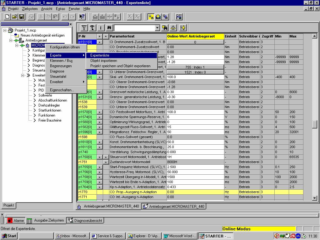
11 Parameter settings Setting the limit, open-loop / closed-loop controlled In the sensorless mode, the MM440 drive inverter operates open-loop controlled in the lower frequency range. The reason for this is that the actual speed can no longer be precisely calculated in the drive inverter itself. In this open-loop controlled range, the motor torque is permanently set. It is not possible to additionally change this value, e.g. via an analog input. This means that it is desirable to reach the limit for the transition into the closed-loop controlled mode at frequencies which are as low as possible. In practice, depending on the drive power and the quality of the optimization, this is possible for frequencies between 1 and 5 Hz. The setting is made in the Expert list (refer to the Fig. below). In order to reach this, click-on <MICROMASTER_440> using the righthand mouse key and the Expert list selected (Step 1). The limits, with values of between 1 and 5 Hz are then entered using parameter P1755 (Steps 2 and 3). In this case it must be observed that a hysteresis (P1756) of 50% referred to P1755 is effective. A&D SD Page 11/15
12
.")
13 Parameter settings Torque boost in the open-loop controlled range and at low requencies This setting is made in the Expert list (refer to the Fig. below). In order to reach this, click-on <MICROMASTER_440> using the righthand mouse key and the Expert list selected (Step 1). The torque in the open-loop controlled range and therefore the tension are set using fixed parameter values. If the frequency is kept constant in the open-loop controlled range, then the torque is entered, using P1610 (refer to the Fig. below, Steps 2 and 3) as a percentage of the rated motor torque. An accelerating torque can be additionally parameterized using P1611 (Steps 4 and 5) in order to accelerate moments of inertia. This is especially practical, if, when starting, the tension F Z in the wire is too low due to the accelerating component of the torque A&D SD Page 13/15
14 Secondary conditions and limitations 6 Secondary conditions and limitations The closed-loop control version with torque limiting, described above, is the simplest way of implementing a closed-loop winder control function and is suitable for basic wire winders. If the control quality has to fulfill higher requirements, then a faster tension controller with tension actual value sensing, diameter sensing and supplementary functions are required. In order to be able to estimate the described closed-loop control versions when engineering an application, the secondary conditions/limitations for an application, which has already been implemented, are listed below. Table 6-1: Technical data of an application example Description Values Comments Wire properties Steel wire with D>1mm With the described closedloop control technique, only possible with steel wire D>1mm. If closed-loop dancer roll control is used (this has not been described here), control is possible with other wire materials down to below D=0.1mm Wire velocity Approx. 150m/min With closed-loop dancer roll position control (this has not been described here) possible up to 2000m/min Minimum roll diameter 0.4m With the closed-loop control Maximum roll diameter 0.8m technique described here, a Dmax / Dmin diameter ratio of max. 4:1 is possible. A&D SD Page 14/15
15 Secondary conditions and limitations Minimum tension force F Zmin at the minimum roll diameter Maximum tension force F Zmax at the minimum roll diameter Tension force characteristic (winding hardness) Motor used Drive inverter used Wire laying drive 55N 270N F Z ~1/D W decreases with increasing diameter 1.1kW, 4 pole with gearbox i=14.48 MM kW, 400V with options: Profibus module Shield connectingplate Sub-chassis line reactor Layed over an approximate width of approx. 0.5m For the closed-loop control techniques described, a tension force ratio F Zmax / F Zmin of max. 5:1 is possible. This is necessary so that for larger roll diameters the wire does not "cut into" the rolls. An MM420 drive is used to lay the wire over the width of the coil A&D SD Page 15/15
Drive System Application
 Drive System Application Example to calculate the limit values for SS1 and SLS Application description for SINAMICS G120 Warranty, liability and support Note The Application Examples are not binding and
Drive System Application
 Drive System Application Operating a MASTERDRIVES braking unit with a MICROMASTER Application description for MICROMASTER 440 Warranty, liability and support Note The Application Examples are not binding
Closed-loop torque control and load distribution
 Application description 01/2014 Closed-loop torque control and load distribution MICROMASTER 440 http://support.automation.siemens.com/ww/view/en/23939668 Warranty and liability Warranty and liability
Welcome to ABB machinery drives training. This training module will introduce you to the ACS850-04, the ABB machinery drive module.
 Welcome to ABB machinery drives training. This training module will introduce you to the ACS850-04, the ABB machinery drive module. 1 Upon the completion of this module, you will be able to describe the
Operating Manual (Edition 04/2004) sinamics. Braking Module / Braking Resistor SINAMICS G130
 sinamics. Braking Module / Braking Resistor SINAMICS G130") Operating Manual (Edition 04/2004) sinamics Braking Module / Braking Resistor SINAMICS G130 04/04 Contents Contents 1 Safety Information 1-1 2 General 2-1 3 Mechanical Installation 3-1 4 Connection 4-1
Operating Manual (Edition 04/2004) sinamics Braking Module / Braking Resistor SINAMICS G130 04/04 Contents Contents 1 Safety Information 1-1 2 General 2-1 3 Mechanical Installation 3-1 4 Connection 4-1
SINAMICS GM150 IGCT version
 /2 Overview /2 Benefits /2 Design /6 Function /8 Selection and ordering data /8 Options Technical data /14 General technical data /15 Control properties /15 Ambient conditions /16 Installation conditions
SINAMICS DCC Winder V4.2. https://support.industry.siemens.com/cs/ww/en/view/
 V4.2 Unrestricted https://support.industry.siemens.com/cs/ww/en/view/38043750 Introduction The application SINAMICS DCC Winder was developed with the objective to address many of the known winder applications
MAGPOWR Spyder-Plus-S1 Tension Control
 MAGPOWR TENSION CONTROL MAGPOWR Spyder-Plus-S1 Tension Control Instruction Manual Figure 1 EN MI 850A351 1 A COPYRIGHT All of the information herein is the exclusive proprietary property of Maxcess International,
Super Calendar. Heated rolls
 Application Assistant Surface Winders are used to roll up material such as wire, paper, film, metals and textiles. The surface winding method applies the driving power to a fixed diameter roll or rolls,
Super Calendar. Heated rolls
 Application Report Surface Winders are used to roll up material such as wire, paper, film, metals and textiles. The surface winding method applies the driving power to a fixed diameter roll or rolls, on
Center Winder Specification
 Center Winder Specification Bump Roll Edge Guide Photo Eye 2000 Ft/ Min Dancer Arm Center Winder Overview Winding is simply a rotational means to take up and package material for more efficient handling
SINAMICS DCM. DC Converter. Application SINAMICS DCM as field supply unit. Edition 04-6/2013. SINAMICS drives
 SINAMICS DCM DC Converter Application SINAMICS DCM as field supply unit Edition 04-6/2013 SINAMICS drives SINAMICS DCM Compact User Manual Legal information Warning notice system This manual contains notices
Technical Explanation for Inverters
 CSM_Inverter_TG_E_1_2 Introduction What Is an Inverter? An inverter controls the frequency of power supplied to an AC motor to control the rotation speed of the motor. Without an inverter, the AC motor
Safety Integrated for entry level personnel SINAMICS. SINAMICS G converters Safety Integrated for entry level personnel. Hazards in plants and
 Hazards in plants and machines 1 Drives with "Safety Integrated" in the application 2 SINAMICS SINAMICS G converters Safety Integrated for entry level personnel An overview of the "Safety Integrated" functions
Small step, big impact: Energy efficiency and dynamic performance
 Small step, big impact: Energy efficiency and dynamic performance The innovative synchronous-reluctance drive system with SIMOTICS motors and SINAMICS converters A new dimension of efficiency siemens.com/reluctance-drive-system
CPW Current Programmed Winder for the 890. Application Handbook. Copyright 2005 by Parker SSD Drives, Inc.
 CPW Current Programmed Winder for the 890. Application Handbook Copyright 2005 by Parker SSD Drives, Inc. All rights strictly reserved. No part of this document may be stored in a retrieval system, or
Guide for Primary Injection Testing WL Circuit Breakers. Document No. : 11-C
 s Guide for Primary Injection Testing WL Circuit Breakers Document No. : 11-C-9036-00 Before Beginning... Qualified Person Siemens type WL circuit breakers should only be only be operated, inspected, and
SINAMICS SM150. 4/2 Overview. 4/2 Benefits. 4/2 Design. 4/6 Function. 4/8 Selection and ordering data. 4/8 Options
 /2 Overview /2 Benefits /2 Design /6 Function /8 Selection and ordering data /8 Options Technical data /1 General technical data /15 Control properties /15 Ambient conditions /16 Installation conditions
Standard Drives A & D SD Application Note
 SENSORLESS VECTOR CONTROL (SVC) Version A, 30.07.99 More detail of Vector Control principles are explained in DA64 Section 2. Some examples of SVC are given in Sections 4.2, 4.3 and 4.4. The MICROMASTER
Good Winding Starts the First 5 Seconds Part 2 Drives Clarence Klassen, P.Eng.
 Good Winding Starts the First 5 Seconds Part 2 Drives Clarence Klassen, P.Eng. Abstract: This is the second part of the "Good Winding Starts" presentation. Here we discuss the drive system and its requirements
SINAMICS G130. Motor reactors. Operating Instructions 05/2010 SINAMICS
 SINAMICS G130 Operating Instructions 05/2010 SINAMICS s Safety information 1 General 2 SINAMICS SINAMICS G130 Mechanical installation 3 Electrical installation 4 Technical specifications 5 Operating Instructions
Converting Applications Made Easy Presented by Jeff Reese Manufacturing in America March 14-15, 2018
 Converting Applications Made Easy Presented by Jeff Reese Manufacturing in America March 14-15, 2018 Before we start A Penny for Your Thoughts At the end of the session, share your feedback via MiA App
Preferred Series 215 kw to 1500 kw. Catalog DA /2000
 s Preferred Series 215 kw to 1500 kw Catalog DA 12.2 1999/2000 Variable-speed drives and equipment in the DA catalog series DA 12 DC Motors for Variable-Speed Drives... SIMOREG Chassis Converters DA 21
RT2DB Excitation and voltage regulation system for synchronous generators
 s RT2DB Excitation and voltage regulation system for synchronous generators Fully digital. Parameter settings done by software. Self monitoring routines. Maintenance free. High reliability. Excellent dynamic
Código de rotor bloqueado Rotor bloqueado, Letra de código. Rotor bloqueado, Letra de código
 Letra de código Código de rotor bloqueado Rotor bloqueado, Letra de código kva / hp kva / hp A 0.00 3.15 L 9.00 10.00 B 3.15 3.55 M 10.00 11.00 C 3.55 4.00 N 11.00 12.50 D 4.00 4.50 P 12.50 14.00 E 4.50
Roll Diameter Requirements in Converting Processes
 Roll Diameter Requirements in Converting Processes www.siemens.com/converting Siemens Industry, Inc. 2016 All rights reserved. Answers for industry. Roll Diameter in Converting Processes Roll diameter
Parker AC10 Frequency Inverter (to 22kW) Easy Start Guide
 Easy Start Guide") Parker AC10 Frequency Inverter (to 22kW) Easy Start Guide CAUTION: 1)Do not re-set while the motor is rotating 2)Perform parts replacement after discharge is finished 3)Do not connect output terminals
Parker AC10 Frequency Inverter (to 22kW) Easy Start Guide CAUTION: 1)Do not re-set while the motor is rotating 2)Perform parts replacement after discharge is finished 3)Do not connect output terminals
Piktronik d. o. o. Cesta k Tamu 17 SI 2000 Maribor, Slovenia Fax:
 PIK tr nik Phone: +386-2-460-2250 Piktronik d. o. o. Cesta k Tamu 17 SI 2000 Maribor, Slovenia Fax: +386-2-460-2255 e-mail: info@piktronik.com www.piktronik.com Sensorless AC motor control for traction
Tension Control Inverter
 Tension Control Inverter MD330 User Manual V0.0 Contents Chapter 1 Overview...1 Chapter 2 Tension Control Principles...2 2.1 Schematic diagram for typical curling tension control...2 2.2 Tension control
Inverter control of low speed Linear Induction Motors
 Inverter control of low speed Linear Induction Motors Stephen Colyer, Jeff Proverbs, Alan Foster Force Engineering Ltd, Old Station Close, Shepshed, UK Tel: +44(0)1509 506 025 Fax: +44(0)1509 505 433 e-mail:
IOM A-0984E IP68-420DC AUTOMATED PILOT ACTUATOR Installation and Operation Manual
 IOM A-0984E IP68-420DC AUTOMATED PILOT ACTUATOR Installation and Operation Manual Please ensure to read and understand the contents of this manual. TABLE OF CONTENTS 1 HEALTH AND SAFETY: READ FIRST...3
Introduction. 1/2 Overview 1/3 Benefits 1/3 Application. 1/3 Order No. code. 1/4 Protection strategy
 /2 Overview /3 Benefits /3 Application /3 Order No. code /4 Protection strategy /5 General technical data /5 Converter-fed operation /7 Motor protection /7 Bearing monitoring /8 Electrical design /8 Motor
SINAMICS drives SINAMICS DCM. DC converters from 6 kw to 2500 kw for variable-speed direct-current drives
 SINAMICS DCM DC converters from 6 kw to 2500 kw for variable-speed direct-current drives Closed-loop control application for a Ward-Leonard block Edition 01-04/2011 SINAMICS drives SINAMICS DCM Compact
Detailed comparison of winding and tension control solutions. Unrestricted Siemens AG 2017
 Detailed comparison of winding and tension control solutions Unrestricted Siemens AG 2018 siemens.com/converting Unrestricted Siemens AG 2017 Agenda 1 2 3 Solutions for tension control solutions Unrestricted
Number 1 in efficiency
 PowerXL DE1 Variable Speed Starter www.eaton.eu/de1 Number 1 in efficiency The easiest way of variable motor speed NEW Variation DE11 The new device category! The PowerXL DE1 Variable Speed Starter The
Designing Drive Systems for Low Web Speeds
 Designing Drive Systems for Low Web Speeds Web Tension Control at Low Speeds Very low web speeds can provide challenges to implementing drive systems with accurate tension control. UNWIND LOAD CELL COOLING
Tension Control Systems
 Technical Considerations Tension Zones I. tension zone in a web processing machine is defined as that area between which the web is captured, or isolated. Virtually any machine can be broken down into
Accessories for Wind Power Inverter WINDY BOY PROTECTION BOX 400 / 500 / 600
 Accessories for Wind Power Inverter WINDY BOY PROTECTION BOX 400 / 500 / 600 Installation Guide WBP-Box-IEN103320 IMEN-WBP-BOX Version 2.0 EN SMA Solar Technology AG Table of Contents Table of Contents
The MICROMASTER has four modes of operation:
 Control Modes The MICROMASTER has four modes of operation: Linear voltage/frequency (410, 420, 440) Quadratic voltage/frequency (410, 420, 440) Flux Current Control (FCC) (440) Sensorless vector frequency
FAQ about Drives Technologie
 FAQ about Drives Technologie Instructions and measures when storing the motors for longer periods of time - as well as commissioning and maintenance of low voltage motors Low Voltage Standard Motors Warranty,
Installation Power Management Unit Battery Cables and Battery Harness
 Installation Power Management Unit Battery Cables and Battery Harness Important Safety Messages SAVE THESE INSTRUCTIONS - This manual contains important instructions that should be followed during installation
Electrical Engineering Info
 Electrical Engineering Info Ready for the New ErP Directives: With Energy- Efficient Solutions for Electric Motors Effective EU regulation EC 640/2009 1.1.2015 Eaton Drives engineering Start IE3 motors
MASTERDRIVE Compact Plus
 MASTERDRIVE Compact Plus The Compact Plus is a member of the MASTERDRIVE product line. The Compact Plus offers many of the same features as the larger MASTERDRIVE products in a smaller package. Compact
System Monitoring SCHOOLMETERBOX AU
 System Monitoring SCHOOLMETERBOX AU Installation Guide SMETER-IEN084710 98-00013210 Version 1.0 EN SMA Solar Technology AG Table of Contents Table of Contents 1 Notes on this Manual..............................
User Guide. Lubricus Lubrication System LUB-D1/LUB-D2/LUB-D3/LUB-D4 (24 VDC)
") User Guide Lubricus Lubrication System LUB-D1/LUB-D2/LUB-D3/LUB-D4 (24 VDC) version 04/2013 Content General Information 3 Warning 3 Scope of Supply 3 Overview 3 General safety details 4 Intended use 4
User Guide Lubricus Lubrication System LUB-D1/LUB-D2/LUB-D3/LUB-D4 (24 VDC) version 04/2013 Content General Information 3 Warning 3 Scope of Supply 3 Overview 3 General safety details 4 Intended use 4
TECHNICAL BRIEF Americas
 TECHNICAL BRIEF Americas Design Considerations When AC Coupling IQ Micros to Battery-Based Systems Overview AC coupling allows use of Enphase Microinverters with battery-based inverter systems. These applications
Operation Manual for Torque Sensors
 Operation Manual for Torque Sensors For below and similar Types DV-14 DH-15 D-2431 DFW-25 DFW-35 D-2223 D-2268 D-2209 DF-30 D-2553 Page 1 of 11 Imprint LORENZ MESSTECHNIK GmbH Manufacturer, Place Lorenz
Application Note EMC - Checklist
 Application Note EMC - Checklist A checklist to avoid EMC trouble General 100151 Title... EMC - Checklist Version... 1.10 Document no.... 100151 Original...en Author... Festo Last saved... 08.08.2017 Copyright
Commissioning Manual AC Servo Actuator LynxDrive SIEMENS SIMODRIVE
 Commissioning Manual AC Servo Actuator LynxDrive SIEMENS SIMODRIVE 06/2017 1017913 Content 1. General... 3 1.1 Description of Safety Alert s... 4 1.2 Disclaimer and Copyright... 4 2. Safety and Installation
Permanent Magnet Synchronous Motor. High Efficiency Industrial Motors
 VoltPro is a new industrial motor range to meet high efficiency needs of industry by higher level of IE4 efficiency class. Main advantage of this product is cost effective solution ensured by using standard
Freedom egen System End-of- Line Functional Checklist
 U Freedom egen System End-of- Line Functional Checklist 976-0361-01-01 Rev A April 2018 DANGER RISK OF FIRE, ELECTRIC SHOCK, EXPLOSION, AND ARC FLASH This checklist is in addition to, and incorporates
690+ Series Integrator
 690+ Series Integrator V/F, Sensorless, Vector Inverter from 1 to 1600 DESCRIPTION The 690+ Series is a single range of AC drives designed to meet the requirements of all variable speed applications from
CENTROIDTM. AC Brushless Drive. Product Spec Sheet
 4 Axis, up to 2 KW motors Brake Output for each axis Overtemp and Overcurrent Protection All-software Configuration Self-cooled Fiber Optic Control CENTROIDTM AC Brushless Drive Product Spec Sheet AC Brushless
Application Note. Common Bussing AC Drives. For 650 and 690+ series drives APP-AC-03
 Application Common Bussing AC Drives APP-AC-03 For 650 and 690+ series drives APP-AC-03 2004 SSD Drives inc. 9225 Forsyth Park Drive, Charlotte, NC 28273 Page of 5 Introduction On occasion, one or more
SCOPELITE TIMING LIGHT OPERATING MANUAL
 SCOPELITE TIMING LIGHT OPERATING MANUAL MOTORTECH Tools & Test Equipment for Ignition Systems P/N 01.10.020-EN Rev. 11/2015 Copyright Copyright 2015 MOTORTECH GmbH. All rights reserved. Distribution and
Serial hoisting equipment with SINAMICS G120
 Application description 07/2016 Serial hoisting equipment with SINAMICS G120 Dimensioning and commissioning http://support.automation.siemens.com/ww/view/en/103156155 Warranty and liability Warranty and
KD LV Motor Protection Relay
 1. Protection Features KD LV Motor Protection Relay Overload (for both cyclic and sustained overload conditions) Locked rotor by vectorial stall Running stall / jam Single phasing / Unbalance Earth leakage
Installation and Maintenance Instructions. World Leader in Modular Torque Limiters. PTM-4 Load Monitor
 World Leader in Modular Torque Limiters Installation and Maintenance Instructions PTM-4 Load Monitor 1304 Twin Oaks Street Wichita Falls, Texas 76302 (940) 723-7800 Fax: (940) 723-7888 E-mail: sales@brunelcorp.com
Assembly instructions
 Please carefully read the assembly instructions before beginning the installation, operation and maintenance of the solar facility. Noncompliance could cause injury to persons or damage to the equipment.
APPLICATION GUIDE. Pure easiness for a wide range of applications ACS580 general purpose drives
 APPLICATION GUIDE Pure easiness for a wide range of applications ACS580 general purpose drives 2 APPLICATION GUIDE ACS580 PURE EASINESS FOR MANY PURPOSES Table of contents 3 Pure easiness for many applications
Technical Manual Electrical Power Supply System T4002
 Technical Manual Electrical Power Supply System T400 MOZELT GmbH & Co. KG Please observe the following safety information and recommendations before start-up! Copyright: MOZELT GmbH & Co. KG, D-4769 Duisburg
Hybrid Motor Technology to Achieve Efficiency Levels Beyond NEMA Premium
 Hybrid Motor Technology to Achieve Efficiency Levels Beyond NEMA Premium Richard R. Schaefer, Baldor Electric Company ABSTRACT This paper will discuss the latest advances in AC motor design that combines
Product Information ECN 425 EQN 437. Absolute Rotary Encoders with Hollow Shaft and Expanding Ring Coupling for Safety-Related Applications
 Product Information ECN 425 EQN 437 Absolute Rotary Encoders with Hollow Shaft and Expanding Ring Coupling for Safety-Related Applications 4/2014 ECN 425, EQN 437 Rotary encoders for absolute position
Kelly HSR Series Motor Controller with Regen User s Manual V 3.3. Kelly HSR Opto-Isolated Series Motor Controller with Regen.
 Kelly HSR Opto-Isolated Series Motor Controller with Regen User s Manual HSR72601 HSR72801 HSR12401 HSR12601 HSR12901 HSR14301 HSR14501 HSR14701 Rev.3.3 Dec. 2011 Contents Chapter 1 Introduction... 2 1.1
Axpert-CSS AMTECH DRIVES Axpert-CSS Amtech
 The Axpert-CSS is a range of Combination Soft Starter panels offered by AMTECH DRIVES. We also offer the module unit as an individual product, named as Axpert-Opti torque Soft Starter. This is only the
Planning and Commissioning Guideline for NORD IE4 Motors with NORD Frequency Inverters
 Planning and Commissioning Guideline for NORD IE4 Motors with NORD Frequency Inverters General Information From their basic function, motors with efficiency class IE4 are synchronous motors and are suitable
Asynchronous motors. 7/2 Main spindle motors for SIMODRIVE 611 7/2 Introduction
 / Main spindle motors for SIMODRIVE 611 / Introduction /4 Main spindle motors for SIMODRIVE 611 1PH motors with solid shaft/forced ventilation /18 Main spindle motors for SIMODRIVE 611 1PH4 motors with
TRIPS AND FAULT FINDING
 WWW.SDS.LTD.UK 0117 9381800 Trips and Fault Finding Chapter 6 6-1 TRIPS AND FAULT FINDING Trips What Happens when a Trip Occurs When a trip occurs, the drive s power stage is immediately disabled causing
Model ER-340XRi / ER-680XRi / ER-1220XRi DC drive product manual HG iss 9 1
 Model ER-340XRi / ER-680XRi / ER-1220XRi DC drive product manual HG102909 iss 9 1 This drive is an isolated 4 Quadrant speed controller for shunt wound or permanent magnet motors. It utilises speed feedback
Features IN THIS CHAPTER
 CHAPTER THREE 3Special Features IN THIS CHAPTER Motor Braking Regeneration Solutions Sharing the Power Bus: V Bus+ and V Bus- Current Foldback (I T Limit) Front Panel Test Points Resolver Alignment ➂ Special
Types of Motor Starters There are several types of motor starters. However, the two most basic types of these electrical devices are:
 Introduction Motor starters are one of the major inventions for motor control applications. As the name suggests, a starter is an electrical device which controls the electrical power for starting a motor.
Web Volume Control Model WV220
 WEB CONTROL PRODUCTS User Manual Web Volume Control Model WV220 1 In accordance with Nexen s established policy of constant product improvement, the specifications contained in this manual are subject
Digital Pressure Regulator Sentronic PLUS Series 614
 Digital Pressure Regulator Sentronic PLUS Series 14 Installation manual IM149-/R01 CONTENTS 1. Description... 1.1 Catalogue number... 1. Operating elements...4 1. Operating modes...4. Electrical connection...5.
Displacement Sensor. Model 8739, 8740, 8741
 w Technical Product Information Displacement Sensor 1. Introduction... 2 2. Preparations for use... 2 2.1 Unpacking... 2 2.2 Grounding and potential connection... 2 2.3 Storage... 2 3. Principle of operation...
Installation instruction Sound Booster Pro Active Sound
 Version 1.03 (20.04.2016) Installation instruction Sound Booster Pro Active Sound Article no. 40180 Audi A6 4G Audi A7 4G Audi Q5 8R www.kufatec.de Kufatec GmbH & Co. KG Dahlienstr. 15 23795 Bad Segeberg
Number 1 in efficiency
 PowerXL DE1 Variable Speed Starter www.eaton.eu/de1 Number 1 in efficiency The new device category! The PowerXL DE1 Variable Speed Starter The PowerXL DE1 Variable Speed Starter one device, all the advantages
Asynchronous motors. 5 Asynchronous motors 5/2 Type overview and rated data 5/4 Technical definitions 5/4 Encoder systems
 / Type overview and rated data /4 Technical definitions /4 Encoder systems / PH7 motors / PH7 motors, forced ventilation / Permissible combinations of mechanical designs for PH7 motors, shaft 8 /4 PL motors
VLT AutomationDrive for marine winch applications
 Application Paper VLT AutomationDrive for marine winch applications www.vlt-marine.danfoss.com This Application Paper is meant to be a guideline for using Danfoss VLT AutomationDrive in winch applications.
BLDPN30001 Series. 30A Brushless DC Controller. User s Guide E. Landon Drive Anaheim, CA
 BLDPN30001 Series 30A Brushless DC Controller User s Guide A N A H E I M A U T O M A T I O N 4985 E. Landon Drive Anaheim, CA 92807 e-mail: info@anaheimautomation.com (714) 992-6990 fax: (714) 992-0471
ADJUSTABLE FREQUENCY CONTROLS SENSORLESS VECTOR CONTROL. Dual Rating. Technologies Inc. mgitech.com NRTL/C CERTIFIED
 ADJUSTABLE FREQUENCY CONTROLS SENSORLESS VECTOR CONTROL Dual Rating NRTL/C CERTIFIED Technologies Inc. mgitech.com Sensor/Sensorless Vector Control Dual current rated for constant and variable torque Auto
TOSVERT VF-S11. V/F control functions
 TOSVERT VF-S11 V/F control functions The technical information in this manual is provided to explain the principal functions and applications of the product, but not to grant you a license to use the intellectual
CETOP POSITION PAPER PP 07
 CETOP POSITION PAPER PP 07 MACHINERY DIRECTIVE 2006/42/EC Valid since 26 th May 2010 CETOP General Secretariat Lyoner Straße 18 D-60528 Frankfurt am Main Phone: +49 69 6603 1201 Fax: +49 69 6603 2201 E-mail:
Inverter MICROMASTER 440
 Inverter MICROMASTER 0 /2 Description / Circuit diagrams /6 Technical data /9 Selection and ordering data /12 Options /2 Dimension drawings Siemens DA 51.2 2003/200 /1 MICROMASTER 0 Description Applications
Winding technology, pneumatically actuated tension brakes web tension open-loop and feedback control systems
 Winding technology, pneumatically actuated tension brakes web tension open-loop and feedback control systems Ortlinghaus Plates. Clutches. Brakes. Systems. 왎 Winding technology - pneumatically actuated
HT Dielectric Withstand Tester Volts AC Output 25mA Leakage Option
 HT-10000 Dielectric Withstand Tester 0-10000 Volts AC Output 25mA Leakage Option Instruction Manual COMPLIANCE WESTUSA Dear Customer: Congratulations! Compliance West USA is proud to present you with your
SIRIUS Soft Starters Introduction
 Introduction Overview Products at a glance 3RW30/3RW31 3RW40 3RW44 Class 73/74 Enclosed 16 CONTROL SIRIUS soft starters for standard applications SIRIUS 3RW30 soft starters SIRIUS 3RW40 soft starters for
DEEP SEA ELECTRONICS PLC DSE3210 Configuration Suite Software Manual
 DEEP SEA ELECTRONICS PLC DSE3210 Configuration Suite Software Manual Document Number 057-152 Author : Paul Gibbons DSE3210 Configuration Suite Software Manual Issue 1 DSE3210 Configuration Suite Software
Installation Instructions. Y-Series Brushless Servo Motor
 Installation Instructions Y-Series Brushless Servo Motor Catalog Number Y-1002-1, Y-1002-2, Y-1003-1, Y-1003-2, Y-2006-1, Y-2006-2, Y-2012-1, Y-2012-2, and Y-3023-2 These installation instructions describe
ZF Friedrichshafen AG Special Driveline Technology. Hysteresis brakes Hysteresis clutches Electronic control unit
 ZF Friedrichshafen G Special Driveline Technology Hysteresis brakes Hysteresis clutches Electronic control unit 2 ZF-Servoplan CG Compact Gearbox ZF-Duoplan 2K Two-speed Gearboxes ZF-Ecolift Elevator Gearboxes
SIMOTION Line Tension Control V Unrestricted / Siemens AG All Rights Reserved.
 SIMOTION Line Tension Control V2.1.1 siemens.com/answers Introduction The application SIMOTION Line Tension Control was developed with the objective to address many of the known tension control applications
SIMOREG SIMOREG DC-MASTER. 6RA70 Series
 SIMOREG DC-MASTER 6RA70 Series Application Improving the performance of DC motors during low-load operation by adopting a form of control that ensures a minimum armature current Edition 1 - October 2008
PowerFlex AC Drives Portfolio
 PowerFlex AC Drives Portfolio PUBLIC INFORMATION 1 Rev 5058-CO900E Copyright 2013 Rockwell Automation, Inc. All Rights Reserved. PUBLIC INFORMATION Copyright 2015 Rockwell Automation, Inc. All Rights Reserved.
MOTORS. Part 2: The Stepping Motor July 8, 2015 ELEC This lab must be handed in at the end of the lab period
 MOTORS Part 2: The Stepping Motor July 8, 2015 ELEC 3105 This lab must be handed in at the end of the lab period 1.0 Introduction The objective of this lab is to examine the operation of a typical stepping
Important instructions
 Operation manual Please read this manual, before starting the unit. It contains important notes on commissioning and handling. Keep these instructions for future reference. Be careful even if you pass
Application Note CTAN #127
 Application Note CTAN #127 Guidelines and Considerations for Common Bus Connection of AC Drives An important advantage of AC drives with a fixed DC is the ability to connect the es together so that energy
Products for specific requirements
 SIDOOR Manual 02/2012 Products for specific requirements Answers for industry. Introduction 1 Safety notes 2 Products for specific requirements SIDOOR Manual Definitions 3 Overview of controls 4 Functions
Tension and Compression Load Cell Model 8435
 Technical Product Information w Tension and Compression Load Cell 1. Introduction... 2 2. Preparing for use... 2 2.1 Unpacking... 2 2.2 Using the instrument for the first time... 2 2.3 Grounding and potential
Servo Motors B-1. Introduction B-2. NX Series B-9. Accessories B-47
 B Servo Motors Servo Motors Introduction B-2 NX Series B-9 Accessories B-47 Introduction NX Accessories This catalog contains information necessary for informed product selection. Additional product details
CSDA Best Practice. Hi-Cycle Concrete Cutting Equipment. Effective Date: Oct 1, 2010 Revised Date:
 CSDA Best Practice Title: Hi-Cycle Concrete Cutting Equipment Issue No: CSDA-BP-010 : Oct 1, 2010 Revised : Introduction Hi-cycle/high frequency concrete cutting equipment has become more prevalent in
Installation & Operation Manual
 Installation & Operation Manual SECO SE 2000 Series DC Motor Controller 1 Through 5 HP 115/230 VAC 1 Phase Input TABLE OF CONTENTS Section Page 1.0 GENERAL INFORMATION... 3 1.1 Controller... 4 1.2 Specifications...