2017 C-MAX HYBRID C-MAX ENERGI MODIFIERS GUIDE
|
|
|
- Belinda Sparks
- 6 years ago
- Views:
Transcription


1 2017 C-MAX HYBRID C-MAX ENERGI MODIFIERS GUIDE
2 TABLE OF CONTENTS INTRODUCTION SECTIONS - Introduction 1 General Information 2 Electrical 3 Mounting 4 Reference NOTE: The descriptions and specifications contained in this guide were in effect at the time this guide was approved for printing. Ford Motor Company reserves the right to discontinue models at any time, or change specifications or design without notice and without incurring any obligation. All rights reserved. Reproduction by any means, electronic or mechanical, including photocopying, recording, or by any information storage and retrieval system or translation in whole or part is not permitted without written authorization from Ford Motor Comapny. Copyright 2017, Ford Motor Company
3 SECTION 0: Introduction Table of Contents Contents PAGE Introduction Genuine Ford Accessories For Your Vehicle Considerations When Using or Installing Accessories
4 0-2 Introduction Introduction Introduction Ford Motor Company has assembled this guide to assist vehicle modifiers in producing a safe and quality vehicle. Ford believes safety and quality come first. To achieve customer satisfaction, we want to assist modifiers in achieving the highest standards of safety and quality in their vehicles. This guide is divided into topics specific to vehicle modifiers. References are made to the current C-Max Hybrid/C-Max Energi Workshop Manual for appropriate service procedures, torque specifications, component separation clearances and any other standard information common to an unmodified vehicle. Specifications unique to this guide are designated. This modifier guide is not a "how-to" book; it should be used as a checklist to help make sure that certain important steps in the modification process are considered. While Ford is providing this information to assist modifiers, it does not warrant the vehicles, methods, materials or the workmanship of the modifier. Ford also does not warrant against failures that result from the modification of a vehicle. Following the guidelines contained in this guide does not assure individual modifiers that the products they modify comply with US Federal or Canadian Motor Vehicle Safety Standards in effect at the time of the modification. The guidelines set forth are based on engineering analysis of typical vehicles. If the guidelines are followed, the modifier's efforts in certifying vehicles to applicable standards should be aided. Compliance testing that may be required for certification of specific vehicle configurations or construction is the sole responsibility of the individual modifier. Genuine Ford Accessories For Your Vehicle A wide selection of genuine Ford accessories are available for your vehicle through your local authorized Ford or Ford of Canada dealer. These quality accessories have been specifically engineered to fulfill your automotive needs; they are custom designed to complement the style and aerodynamic appearance of your vehicle. In addition, each accessory is made from high-quality materials that meet or exceed Ford's rigorous engineering and safety specifications. Ford Motor Company will repair or replace any properly installed genuine Ford accessory found to be defective in factory-supplied materials or workmanship during the warranty period, as well as any component damaged by the defective accessory. The accessory will be warranted for whichever provides you the greatest benefit: 12 months or 20,000 km (12,000 mi), whichever occurs first; or the remainder of your new vehicle limited warranty. This means that genuine Ford accessories purchased along with your new vehicle and installed by the dealer are covered for the full length of your new vehicle's limited warranty 3 years or 60,000 km (36,000 mi), whichever occurs first. Contact your dealer for details and a copy of the warranty. Considerations When Using or Installing Accessories For maximum vehicle performance, keep the following information in mind when adding accessories or equipment to your vehicle: When adding accessories, equipment, passengers and/or luggage to your vehicle, do not exceed the gross vehicle weight rating (GVWR) or gross axle weight rating (GAWR) as indicated on the Safety Compliance Certification Label. Consult your dealer for specific weight information. The Federal Communications Commission (FCC) and Canadian Radio Telecommunications Commission (CRTC) regulates the use of mobile communication systems, such as 2-way radios, telephones and theft alarms that are equipped with radio transmitters. Any such equipment installed in your vehicle should comply with FCC or CRTC regulations and should only be installed by a qualified service technician. Mobile communication systems may harm the operation of your vehicle, particularly if they are not properly designed for automotive use. To avoid interference with other vehicle functions, such as the anti-lock brake system (ABS), amateur radio users who install radios and antennas onto their vehicle should not locate the antenna in the area of the driver's side hood. Electrical or electronic accessories or components that are added to the vehicle by the dealer or the owner may adversely affect battery performance and durability.
5 SECTION 1: General Information Table of Contents Contents PAGE Section 1: General Information Important Safety Notice Warnings, Notices and Notes Making Safety Devices and Elements Inoperative Process and Quality Assurance Systems Quality Assurance Minimum and Maximum Screw Sizes Tire Replacement Requirements Using Snow Tires and Traction Devices Vehicle Loading Vehicle Storage General Vehicle Storage Electrical Vehicle Storage Body Vehicle Storage Engine Vehicle Storage Fuel System Vehicle Storage Tires
6 1-2 General Information Section 1: General Information Section 1: General Information Important Safety Notice NOTE: The descriptions and specifications contained in this guide were in effect at the time this guide was approved for printing. Ford Motor Company reserves the right to discontinue models at any time, or change specifications or design without notice and without incurring obligation. Appropriate repair methods and procedures are essential for the safe, reliable operation of all motor vehicles as well as the personal safety of the individual doing the work. This guide provides general direction and guidelines for performing modifications to the C-Max Hybrid and C- Max Energi vehicles, it will also help assure reliability. There are numerous variations in procedures, techniques, tools and parts for modifying vehicles, as well as in the skill level of the individual doing the work. This guide cannot possibly anticipate all such variations and provide advice or cautions as to each. Accordingly, anyone who departs from the instructions provided in this guide must first establish that they compromise neither their personal safety nor the vehicle integrity by the choice of methods, tools or parts. Warnings, Notices and Notes As you read through this guide, you will come across WARNINGS, NOTICES and NOTES. Each one is there for a specific purpose. WARNINGS remind you to be especially careful in those areas where carelessness can cause you personal injury. NOTICES are given to prevent you from making an error that could damage the vehicle or the vehicle's components. NOTES give you added information that will help you to complete a particular procedure. The following list contains some generalized warnings that you should follow when working on a vehicle. WARNING: The nominal voltage of the high voltage traction battery (HVTB) is approximately 300 volts DC. The HVTB and it's charging system contain high voltage components and wiring. High voltage cables and wiring are orange in color. Before carrying out any vehicle modifications, the HVTB must be depowered. Any modification, service, or repairs to the high voltage system or it's components, must be done by a trained service technician. Failure to follow these instructions may result in severe personal injury or death. For eye protection, always wear safety glasses. Use safety stands whenever a procedure requires you to be under the vehicle. Make sure that the ignition switch is always in the OFF position, unless otherwise required by the procedure. Set the parking brake when working on the vehicle. The gear selector should be set in PARK unless instructed otherwise for a specific operation. Place wood blocks (4 inch x 4 inch or larger) against the front and rear surfaces of the tires to help prevent the vehicle from moving. To avoid the danger of carbon monoxide poisoning, operate the engine only in a well-ventilated area. To reduce the risk of serious burns, avoid contact with hot metal parts such as the radiator, exhaust manifold, tailpipe, catalytic converter or muffler. Keep yourself and your clothing away from moving parts when the engine is running, especially the drive belts. Do not smoke while working on a vehicle. To reduce the risk of injury, always remove rings, watches, loose hanging jewelry and loose clothing before working on a vehicle. When it is necessary to work under the hood, keep hands and other objects clear of the cooling fan blades. Failure to follow these instructions may result in personal injury or death. NOTICE: Do not modify the cooling system in any manner. Electric vehicle components could possibly be damaged if any cooling system modifications are attempted. Do not install any type of accessory push/bull bar as it may restrict air flow into the system. Do not disable the air conditioning (A/C) system. The HVTB cooling system utilizes the cabin air to cool the HVTB. Before placing the vehicle in a paint booth, make sure that the HVTB is not installed in the vehicle. In addition, the Charge Port Light Ring (CPLR) must be covered / protected from heat. High paint booth temperatures may damage the HVTB and the CPLR. Remove the service disconnect from the HVTB while carrying out any vehicle modifications.
7 General Information 1-3 Section 1: General Information Making Safety Devices and Elements Inoperative The vehicle contains many safety features required by US Federal or Canadian Motor Vehicle Safety Standards. These features, which include the key-on-ignition chime and brake lights, should never be disabled or modified. CFR 49 Section states that "A manufacturer, distributor, dealer or motor vehicle repair business may not knowingly make inoperative any part of a device or element of design installed on or in a motor vehicle or motor vehicle's equipment in compliance with an applicable motor vehicle safety standard prescribed under this chapter unless the manufacturer, distributor, dealer or repair business reasonably believes the vehicle or equipment will not be used (except for testing or a similar purpose during maintenance or repair) when the device or element is inoperative." Process and Quality Assurance Systems A formalized Process and Quality Assurance Systems check may be helpful in consistently producing high-quality products. An overview of some of the key items for such a system are outlined in this section. Quality Assurance Completed unit sign-off: All control items should be inspected with a written sign-off. All labels should be inspected and signed off, including verification that the information on the labels is correct. All appropriate systems should be checked for leaks. A road test should be performed to verify that all systems are operating correctly. All systems and functions that were provided by Ford should be checked to make sure that they function correctly after the build process. The modifier's Process and Quality Assurance Systems should also make sure that appropriate training is provided to the employees. Minimum and Maximum Screw Sizes When installing aftermarket equipment, avoid using fasteners that are too long for the application or are in an area which might damage vehicle components, including the low-voltage wiring, the high voltage system including the HVTB and the (orange) high voltage wiring/cables, brake lines, fuel tank and lines, powertrain components, HVAC components, exhaust system or suspension. Tire Replacement Requirements WARNING: Only use replacement tires and wheels that are the same size and type (such as P-metric versus LT-metric or all-season versus allterrain) as those originally provided by Ford. Use of any tire or wheel not recommended by Ford can affect the safety and performance of your vehicle, which could result in an increased risk of the loss of vehicle control, vehicle rollover, personal injury or death. Additionally, the use of non-recommended tires and wheels could cause steering or suspension failure. If you have questions regarding tire replacement, see an authorized Ford or Lincoln dealer. NOTICE: Do not install an off road, aggressive tread or incorrectly sized tire. Any of these may cause elevated stress to the steering system. This can cause the power steering system to overheat and shut off the power assist, which can affect the safety and performance of your vehicle. NOTE: The C-Max Hybrid and C-Max Energi vehicles are equipped with a reduced rolling resistance tire design. The use of a different tire can affect the handling and fuel economy of the vehicle. Because it can affect the safety and performance of your vehicle, which could result in an increase in risk of losing control of the vehicle, make sure all tires and wheels on the vehicle are the same size, type, tread design, brand, load-carrying capacity and speed rating. Using Snow Tires and Traction Devices NOTE: Snow tires must be the same size and grade as originally equipped on your vehicle. The tires on your vehicle have all-weather tread to provide traction in the rain and snow; however, in some climates, using snow tires or traction devices may be necessary. Follow these guidelines when using snow tires and traction devices: SAE Class "S" cables should ONLY be used on the vehicle front tires. Install cables or chains securely, verifying that the cables or chains do not touch any wiring or brake lines.
8 1-4 General Information Section 1: General Information Drive cautiously! If you hear the cables or chains rub or bang against the vehicle, stop and retighten them. If this does not work, remove the cables or chains to prevent vehicle damage. Avoid overloading your vehicle. Remove the cables or chains when they are no longer needed; do not use cables or chains on dry roads. Do not exceed 48 km/h (30 mph) with tire cables or chains on your vehicle. Consult your dealer for information on other Ford approved methods of traction control. Vehicle Loading WARNING: The appropriate loading capacity of your vehicle can be limited either by volume capacity (how much space is available) or by payload capacity (how much weight the vehicle should carry). Once you have reached the maximum payload of your vehicle, do not add more cargo, even if there is space available. Overloading or improperly loading your vehicle can contribute to the loss of vehicle control and vehicle rollover. WARNING: Exceeding the Safety Compliance Certification Label axle and/or vehicle weight rating limits could result in substandard vehicle handling or performance, engine, transmission and/or structural damage, serious damage to the vehicle, loss of control and personal injury. GVWR is the maximum allowable weight of the fully loaded vehicle (including all options, equipment, passengers and cargo). The GVWR is shown on the Safety Compliance Certification Label located on the B-pillar or the edge of the driver's door. GAWR is the maximum allowable weight that can be carried by a single axle (front or rear). These numbers are shown on the Safety Compliance Certification Label located on the B-pillar or the edge of the driver's door. The total load on each axle must never exceed its GAWR. WARNING: Do not use replacement tires with lower load carrying capacities than the original tires because they may lower the vehicle's gross vehicle weight rating (GVWR) and gross axle weight rating (GAWR) limitations. Replacement tires with a higher limit than the originals do not increase the GVWR and GAWR limitations. Steps for determining the correct load limit: Locate the statement "The combined weight of occupants and cargo should never exceed XXX kg or XXX lb" on your vehicle's placard. Determine the combined weight of the driver and passengers that will be riding in your vehicle. Subtract the combined weight of the driver and passengers from XXX kg or XXX lb. The resulting figure equals the available amount of cargo and luggage load capacity. For example, if the "XXX" amount equals 1,400 lb and there will be five 150 lb passengers in your vehicle, the amount of available cargo and luggage load capacity is 650 lb ( (5 x 150) = 650 lb). In metric units ( (5 x 68) = 295 kg). Determine the combined weight of luggage and cargo being loaded on the vehicle. That weight may not safely exceed the available cargo and luggage load capacity calculated in the step above. Vehicle Storage General Vehicles should be stored in a dry, ventilated place and protected from sunlight, if possible. If vehicles are stored outside, maintenance against rust and damage, as described below, is recommended. NOTICE: Keep all rubber parts free from oil and solvents. Vehicle Storage Electrical NOTICE: If your vehicle is to be stored for 30 days or longer, disconnect the low-voltage (underhood) battery negative terminal. Failure to do this could damage the vehicle's battery.
9 General Information 1-5 Section 1: General Information NOTE: Extended storage time which results in the discharge of the low and/or high voltage batteries, may result in the setting of DTCs and/or a nostart condition. To maintain the high voltage battery charge, charge the high voltage batteries once a month. This maintains the high voltage battery, but may not be enough to maintain the low-voltage (underhood) battery. Additional low-voltage (underhood) battery charging may be required after 60 days. Vehicle Storage Body Wash the vehicle thoroughly to remove any contaminants from the exterior surfaces and underside. Periodically wash vehicles stored in exposed locations. Touch up any exposed raw or primed metal to provide rust protection. Cover chrome and stainless steel parts with a thick coat of auto wax to prevent discoloration. Rewax as necessary when the vehicle is washed. Lubricate the hood hinges, door hinges and latches with a light-grade oil. Cover the interior soft trim to prevent fading. Vehicle Storage Engine Start the engine every month and run it until it reaches normal operating temperature. While pressing the brake pedal, shift the transmission through all the gears while the engine is idling. Vehicle Storage Fuel System Regularly move vehicles short distances to mix fuel anti-oxidation agents. NOTE: During extended periods of vehicle storage (60 days or more), gasoline may deteriorate due to oxidation. This can damage rubber and other polymers in the fuel system and may clog small orifices. A commercially gasoline fuel stabilizer (Sta-Bil or equivalent) should be added to gasoline-powered vehicles whenever actual or expected storage periods exceed 60 days. The manufacturer's instructions packaged with the product should be followed. The vehicle should then be operated at an idle speed to circulate the additive throughout the fuel system. Vehicle Storage Tires Most high-performance tires are made with nylon overlay. As such, the following steps should be taken to avoid flat spots on the tires when the vehicle is not used for a period of time. Keep the vehicle's tire pressure at the recommended operating pressure. If the vehicle is stored for a period longer than 15 days, it should be moved several feet during each 15-day period so that a different portion of the tread contacts the ground.
10 SECTION 2: Electrical Table of Contents Contents PAGE Electrical Basics Electrical Terms Control Modules Red Area Controller Area Network (CAN) Bus Communication Equipment Vehicle Speed Signal Disabling Brake Lights Disabling the A/C System High and Low-Voltage Systems Volt Battery High Voltage Traction Battery (HVTB) High Voltage Traction Battery (HVTB) Systems Depowering DC/DC Converter DC/AC Inverter and AC Power Point (C-Max Hybrid and C-Max Energi only) Auxiliary Power Point 12V Electrical Systems Management Vehicle Component Electrical Loads Typical Police/Taxi Equipment General Guidelines Keep-Alive Memory (KAM) Power Equipment Grounding Guidelines Wire Insulation Terminals and Connectors Circuit Protection and Electrical Load Wire Protection Requirements Electrical Protection Mechanical/Environmental Protection Grommets and Sealing Requirements Wire Routing Wire Retention and Routing Splices and Repairs Recommended Splicing Method Solder (For 16 AWG and Smaller Diameter Wire Only) Heat Shrinkable Tubing (Heat Shrink) (Ford Specification ESB-M99D56-A2) Recommended Splicing Method Crimp (For AWG Diameter Wire to Like Wire Diameter) Wiring Reference Information Wiring Diagrams - Charging Systems Connector End Views Ground
11 2-2 Electrical Electrical Basics Throughout a vehicle, electricity is supplied through "hot" wires, comparable to the pressurized supply pipes of a plumbing system. At various points along the wires are electrical loads in the form of lights, switches and receptacles. Turning on a light switch is somewhat like opening a faucet to let water run: electricity flows through the hot wire to make the light illuminate. Once the electricity has done its work, its potential drops to zero, just as water loses pressure after flowing through a sink or laundry tub. The electrical system has drains, which are the ground wires that return the electricity to its source, just as a plumbing system has drain pipes through which water runs into the sewer mains or ground. The lights or equipment, technically called the load, can be compared to a water wheel that remains motionless until a stream of water causes it to turn. A load consists of a resistance, a material that permits the passage of electricity, but only with difficulty and thereby creates heat. Resistance to electricity flowing through a wire can be compared to the resistance given to water flowing through a hose, as if the hose were to be squeezed, it would restrict the flow of water. A load may also be inductive, typically a motor with windings of copper wire, in which the magnetic fields generated by the electrical current creates motion. Here are some more examples of resistive loads: tungsten filament of an incandescent bulb; heating element of an electric heater in a coffee pot. The demand on an electrical system depends on the number of loads in operation and their consumption of energy, just as demands on a water system depend on how many faucets are opened and how wide they are opened. The mechanics and physical fittings of the system are simple. Electricity moves throughout the vehicle in wires of different sizes, according to the electricity a circuit may have to carry. Electrical Terms VOLT is the unit of electrical potential, equal to the difference of electrical potential between 2 points in a circuit. It could be compared to the pressure, or the push, on the water to move it through a pipe. AMPERE or AMPS is the unit used to measure the amount of electrical flow; the number of electrically charged particles called electrons that flow past a given point in a circuit. It is similar to measuring the amount of water flowing through a pipe at any given point. The larger the pipe is, the more water that can flow past one given point per second. Similarly, the bigger the wire is, the more electricity that can flow past a given point. WATT is the unit of power. It indicates the rate a device converts electric current to another form of energy, either heat or motion. Or to put it another way, the rate at which a device converts energy. The relationship of volts, amperes and watts to one another is expressed in a simple equation that enables you to make any calculations you may need for proper and safe electrical modifications to the vehicle. Volts x Amps = watts. If the current is at 12 volts and a device requires 4 amperes of current, the equation will read 12 volts x 4 amperes = 48 watts. To figure the current needed for a device rated in watts, turn the equation around: Watts/volts = amperes. For example, if you have a piece of equipment, such as a communications radio, that uses 120 watts: 120 watts/12 volts = 10 amperes. Control Modules Red Area Do not install any components into the control modules or module harness. Connecting into this system may affect control module operation. For example, connecting aftermarket electrical equipment into the brake light circuit or any other circuit which is connected to the PCM, antilock brake computer, air bag system or any other vehicle system will cause vehicle malfunction. Controller Area Network (CAN) Bus NOTICE: Wiring faults in the controller area network (CAN) bus may shut down the vehicle and prevent further operation. Do not splice or connect any equipment to the controller area network (CAN) bus wiring. Communication Equipment Mobile communication systems may harm vehicle operation, particularly if they are not properly designed for automotive use or are not properly installed. Citizen band (CB) transceivers, garage door openers and other transmitters whose power output is 5 watts or less will not ordinarily affect the operation of the vehicle. Vehicle Speed Signal The vehicle speed signal is sent from the PCM and is transmitted through the CAN bus. The BCM receives this signal and produces a hardwired frequency Modulated output. The BCM sources the Discreet_VSPD_Ckt which is the 8000 pulses per mile frequency output.
12 Electrical 2-3 Disabling Brake Lights Do not disable the brake light circuits for any reason. Disabling the A/C System Do not disable the A/C system. The cabin air is used to help cool the HVTB. High and Low-Voltage Systems NOTICE: Do not backprobe or splice into the high voltage system. Voltage in the system is approximately 300V DC. Damage may occur to equipment added to the system. The high voltage system has a floating ground. When the engine is operating or the vehicle is moving, the high voltage generator begins to generate high voltage, AC electricity. High voltage AC electricity can be consumed or generated by the motor generator, the traction motor or a combination of both motors. Excess high voltage current is converted from high voltage AC to high voltage DC electrical power inside the motor generator unit and transmitted through the high voltage (orange) cables. The high voltage DC electrical power is converted to lowvoltage DC electrical power through the DC/DC converter. This low-voltage DC electrical power is then supplied to the 12-volt battery through the low-voltage battery cables. 12 Volt Battery The 12 volt battery is a standard automotive battery. It is a DC source connected in a negative ground system. The battery case is sealed, with 2 vent holes to release gases. The battery has 3 major functions: Storage of electricity for later use. Voltage stabilizer for the electrical system. Temporary power source when electrical loads exceed the DC/DC converter output current. High Voltage Traction Battery (HVTB) WARNING: Do not backprobe, splice or repair the high voltage (orange) wiring. The nominal High Voltage Traction Battery (HVTB) voltage is approximately 300 volts DC. Damage may occur to equipment added to the system. The HVTB is a 300 volts DC source connected in a floating ground system. The battery receives, stores and delivers high voltage electrical power when required by the vehicle control strategy. On the HVTB there is a battery energy control module (BECM). None of the BECM wiring should be tapped or spliced to check for battery voltage (power), ground or signals. There is also the bussed electrical center (BEC) which houses the contactors, current sensor and the associated components. The service disconnect is mounted between the BEC and the vehicle high voltage system and is used to disconnect the high voltage from the vehicle system. High Voltage Traction Battery (HVTB) Systems Depowering WARNING: The high voltage system may retain a dangerous level of voltage for a short time after the service disconnect has been removed. Wait 5 minutes for the voltage to dissipate before beginning service. Failure to follow this instruction may result in serious personal injury or death. WARNING: To prevent the risk of high voltage shock, always follow precisely all warnings and service instructions, including instructions to depower the system. The high voltage system utilizes approximately 300 volts dc, provided through high voltage cables to its components and modules. The high voltage cables and wiring are identified by orange harness tape or orange wire covering. All high voltage components are marked with high voltage warning labels with a high voltage symbol. Failure to follow these instructions may result in serious personal injury or death. NOTE: The high-voltage service disconnect is located behind the rear fold down seats. 1. Position the vehicle in the repair bay.


13 2-4 Electrical 2. Turn the ignition switch to the OFF position. 3. Fold the rear seat backrest down, position the load floor up and remove the high voltage battery disconnect cover. NOTE: C-MAX Hybrid shown. NOTE: C-MAX Energi shown. 4. Pull to remove the battery high voltage service disconnect interlock cover. NOTE: C-MAX Hybrid shown.


14 Electrical 2-5 NOTE: C-MAX Energi shown. 5. Remove the battery high voltage service disconnect: a. Pull the lever position assurance (LPA) tab toward the front of vehicle to remove. b. Pull the lever handle outward to disengage the interlock. c. Rotate the lever to horizontal and remove the battery high voltage service disconnect. NOTE: C-MAX Hybrid shown.
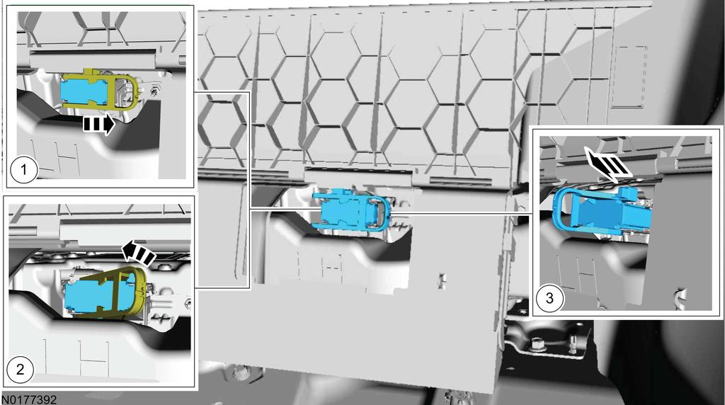
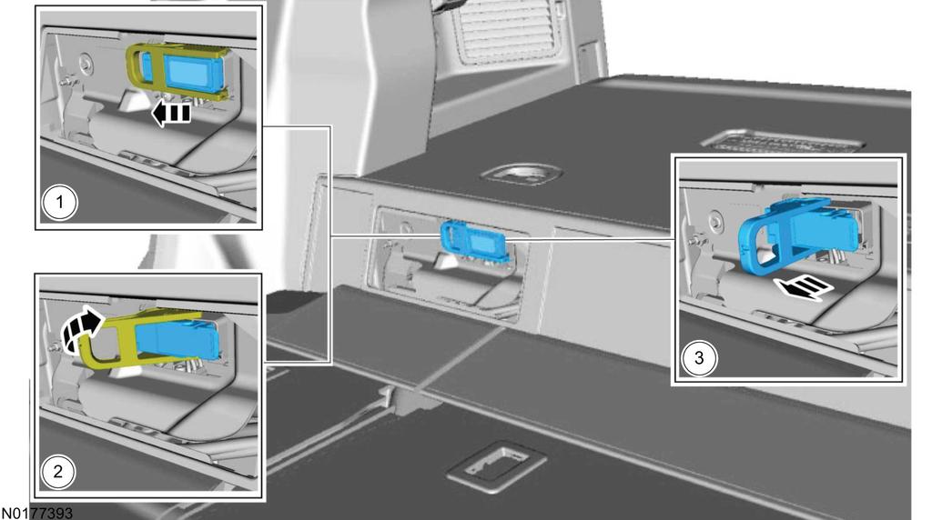
15 2-6 Electrical NOTE: C-MAX Energi shown.
16 Electrical Wait 5 minutes after the service disconnect has been removed before continuing service. This allows any residual voltage in the high voltage system to dissipate. 7. To repower the system, reverse the depowering procedure. DC/DC Converter The DC/DC converter is an air-cooled component that converts high voltage DC power to low-voltage DC power. It is located within the high voltage battery pack and maintains an electrical isolation between the 2 DC power systems. This system converts the high voltage (approximately 300 volts) to low voltage (12 volts) which in turn, provides power to the vehicle low-voltage battery systems. The PCM controls the DC/DC converter operation through an enabled input from the PCM to the DC/DC converter. DC/AC Inverter and AC Power Point (C-Max Hybrid and C-Max Energi only) NOTE: Do not keep an electrical device plugged into the power point when the device is not in use. It is not recommended to use any extension cord with the 110V AC power point, since it will defeat the safety protection design provided by the cap and twist tab. It will also cause the power point to overload due to powering multiple devices that can reach beyond the 150 watt load limit. The DC/AC inverter converts 12-volt DC to 110-volt AC to power a device that uses AC with a rating of less than 150 watts. The power point automatically shuts off if the load exceeds 150 watts. This prevents damage to the inverter or load. The inverter supplies 110-volt AC power only when the key is in the ON/START position. This reduces the draw on the 12-volt system when the vehicle is not running. The DC/AC inverter outlet (AC power point) is equipped with a green LED that indicates the system integrity. The green LED illuminates continuously when the key is in the ON/START position and the system is operating normally. The green LED flashes constantly if the key is in the ON/ START position and a fault is detected. Short circuits, overloads or overheating of the inverter causes the green LED to flash and the power to be cut off to the outlet. If the LED is flashing, the problem must be corrected. If the inverter has overheated, with no load connected, it must have time to cool off. The power outlet is not designed for the following electric appliances; they may not work properly: Cathode ray tube-type televisions. Motor loads, such as vacuum cleaners, electric saws and other electric power tools, compressor-driven refrigerators. Measuring devices, which process precise data, such as medical equipment, measuring equipment. Other appliances requiring an extremely stable power supply: microcomputer-controlled electric blankets, touch sensor lamps. Auxiliary Power Point 12V WARNING: The nominal High Voltage Traction Battery (HVTB) voltage is approximately 364 volts DC. The HVTB and charging system contain high voltage components and wiring. High voltage cables and wiring are orange in color. Before carrying out any vehicle modifications, the HVTB must be depowered. Any modification, service, or repairs to the high voltage system or it's components, must be done by a trained service technician. Failure to follow these instructions may result in severe personal injury or death. NOTICE: Power outlets are designed for accessory plugs only. Do not insert any other object in the power outlet as this will damage the outlet and blow the fuse. Do not hang any type of accessory or accessory bracket from the plug. Improper use of the power outlet can cause damage not covered by your warranty. NOTE: Do not use the power point for operating the cigarette lighter element (if equipped). To prevent the fuse from being blown, do not use the power point(s) over the vehicle capacity of 12V DC/180W. To prevent the battery from being discharged, do not use the power point longer than necessary. Electrical Systems Management Care must be given in deciding what equipment should be installed into a vehicle given the power demands of the equipment and the power available from the vehicle. Develop a power load strategy to minimize the risk of running out of power. Examine the proposed equipment for vehicle installation. Add up the current requirements. If the current requirements exceed what the vehicle can reasonably be expected to provide, the battery begins discharging to provide the power to the equipment that the generator is unable to provide. After some period of time, the vehicle shuts off as the battery voltage decreases to a level that cannot sustain vehicle operation.
17 2-8 Electrical There are alternatives that can be considered to minimize system electrical overload. Consider the current requirements of equipment before it is purchased and installed. For example, modern light bars and radios use a fraction of the current than units made as recently as The light bar is the most power intensive unit installed on most vehicles, considerable attention should be given to its current requirement. Changes in driver habits can make a difference in the electrical system load and will impact available power as well. When a vehicle is sitting and no one is in the car, certain electrical equipment can be turned off until the driver is ready to get back into the vehicle. Vehicle Component Electrical Loads Vehicle component electrical loads are shown in the table below. Not all features are powered all the time, so actual vehicle loads on the power supply system will vary. NOTE: The electric A/C compressor loads are included with the blower loads. Base Component Miscellaneous base loads 16.5 Cooling Cooling fan (high speed variable) 27.0 Climate Control A/C fan to face high speed (recirculating air) 25.0 A/C fan to face M/H speed (recirculating air) 16.0 Heater fan to foot M/H speed (fresh air) 16.0 Lighting Exterior and instrument panel lamps (non-dimmable) 3.5 Headlamps low beam 9.1 Brake lights (with CHMSL) 5.1 Heated Features Heated rear window (includes heated mirrors) 18.0 Heated front seat LH 4.5 Heated front seat RH 4.5 Other Radio 4.0 Typical Vehicle Load = Amps Typical Police/Taxi Equipment Loads for equipment commonly found on police vehicles are shown in the table below. Not all equipment will be operating at the same time, so actual loads on the power supply system will vary. Amps Component Amps Communications radio Light bar LED light bar 6.0 Siren Headlamp flasher
18 Electrical 2-9 (Continued) Component LED deck bars/led visor lights 2.0 Radar 0.8 Taximeter 3.3 Receipt printer 3.0 Spotlights (each) 7.8 Alley lights (each) 1.0 Camcorder 2.0 General Guidelines Do not modify the cooling system in any manner. Electric vehicle components could possibly be damaged if any cooling system modifications are attempted. Do not install any type of accessory push/bull bar as it may restrict air flow into the cooling system. Do not disable the air conditioning (A/C) system. The HVTB cooling system utilizes the cabin air to cool the HVTB. Do not backprobe, splice or repair the high voltage system (orange) wiring/cables. Do not mount to or modify the high voltage system (orange) wiring/cables in any way. Do not cut, weld or screw into the HVTB case or penetrate the batteries in any way. Air bag restraint systems must remain intact as received from Ford Motor Company. Before modifications are done to the vehicle, the system must be depowered by following the instructions provided in the current C-Max Hybrid/Energi Workshop Manual. Provide circuit protection (fuses) for all wiring. The fuse rating should not exceed either the rated wiring current capacity or the total current requirements for all the add-on components on the circuit. Install fuses as close to the point of tapped power as possible. Provide protective covering in all areas that could be damaged during normal equipment installations. Do not allow control panels attached to the instrument panel to protrude into the driver and passenger air bag deployment zones. For additional information, refer to Section 4: Reference in this guide. Do not install switches and gauges in the driver or passenger knee impact areas. Provide adequate retention for wiring harnesses so they are clear of bolts, corners or edges which could abrade the wires during normal vehicle operation. Properly secure all wiring relocated or removed while working behind the instrument panel to prevent chafing, squeaks and rattles. Anticipate misrouted wiring situations and protect all wiring from penetration by screws and raw edges. Weather-seal all electrical connectors exposed to the elements. Do not use quick splice connectors or wire nuts. Install the fuse panel so fuses are readily accessible. Make sure that connections are easily accessible for assembly and service. Inspect all Ford gauges, lights and switches for correct operation after instrument panel work is performed. Make sure submersible connectors do not lose their seals under extreme assembly conditions such as bending wires 90 degrees immediately after the connector. Whenever using connectors, use a socket (female) connector on the electrical source side and a plug (male) connector on the electrical load side to reduce the possibility of a short circuit when disconnected. Adherence to the above guidelines is not to be construed as approval by Ford Motor Company of any specific revisions or additions to the vehicles original electrical system. Document all revisions to the electrical system and place with the vehicle Owner's Literature. Color code and/or label all revisions or additions to wiring. Disconnect the negative battery cable of vehicles stored on-site to reduce the possibility of draining the battery by lights or other equipment. Keep-Alive Memory (KAM) Power The electronic motor and/or transmission control modules and the HVTB BECM require low battery voltage (12 volts) to be supplied at all times to maintain the KAM. Keep this in mind when installing load disconnect switches or solenoids. Equipment Grounding Guidelines Amps NOTICE: Do not use/modify any of the high voltage system grounds or damage to the high voltage components may occur.
19 2-10 Electrical Do not ground the body to the transmission or transmission crossmember. Ground accessories to the chassis or the vehicle battery. Splicing into circuitry relating to the electronic engine and/or transmission control systems is not acceptable because of the adverse effect on the electronic system operation. Adequately protect electrical connections exposed to the elements. Wire Insulation Polyvinyl chloride (PVC) rated at 90 C (194 F) is the standard wire insulation acceptable for inside body use but not acceptable for underhood/underbody wiring. Hypalon insulation should be used on links only (Ford specification ESB-M1L54-A). Cross-linked polyethylene (XPLPE or SXL) rated at 125 C (257 F) is the required insulation for underhood/underbody applications (Ford specification ESB-M1L123-A). GXL can be used as an alternate wire (Ford specification ESB-M7L85B) as long as the concentricity specifications are met. To provide a water-resistant seal in conjunction with crimp connectors, a Duraseal crimp connector is recommended since it is designed to account for outside wire diameter that is smaller than the present SXL wire. Terminals and Connectors Connector Types: Submersible (sealed) A connector that is capable of being immersed in water. Weather-resistant A connector that will retain its sealing and connection qualities while being exposed to adverse weather conditions. Duraseal crimp A supplier trade name for a sealed wiring repair or splice. When a connection is not defined (typical situation harness-to-harness connectors), the following suggestions should be implemented: Determine the connector type. If it will be located in a hostile environment, use a sealed connector; if not, use an open connector. A hostile environment is defined as being exposed to water and/or salt accumulation and/or high temperatures (that is; underhood, exterior panels and footwells). Use in-line connectors with secondary locks to prevent the terminal from being pushed out. Do not use single wires smaller than 14 gauge in a 2-way or larger weather-resistant connector (the very large style), since the wire may break during disengagement. Use Hypalon, XLPE or Elexar insulation in submersible connectors to maintain sealing integrity. PVC is not acceptable because its properties allow it to set in a deformed pattern, therefore compromising the integrity of the seal. Determine the terminal type. Base your decision on wire gauge, current carrying capacity, connector type and insulation type. Use non-detent low insertion force terminals whenever possible. Do not use low insertion force female terminals in weather-resistant connectors. Analyze circuit requirements (signal levels, current, voltage) to determine the proper plating material (such as gold). Use of non-plated terminals is not recommended. Do not use plugs to seal holes in micropin connector grommets. It is very easy to forget to insert them during manufacturing and ruin the seal. Use a grommet with only the necessary number of holes or use dummy wires at least 600 mm (24 in) long. Fully align connectors prior to terminal connection terminal cavities should have minimum tolerance to prevent terminals from floating, bending or pin push-out during mating/engagement. Make sure connectors of similar type and color are identifiable to the operator to eliminate crossed connections and minimize assembly time. Avoid using similar types and colors of connectors close together. Be sure that connectors have positive locking devices that allow easy installation with a low insertion force and easy removal. The connector snap should be easily felt and heard. Eliminate the use of edgeboard, tang-type and molded-over connectors. The use of blade-type weather-resistant connectors is restricted to high-current applications which cannot be handled by submersible connectors. Circuit Protection and Electrical Load Modification to the vehicles existing low-voltage (12 volts) wiring should be done only with caution and careful consideration of effects on the completed vehicles electrical system. Anticipated circuitry should be studied to determine the required circuit protection and to avoid feedback loops. Added circuitry must be protected either by a base vehicle fuse or circuit breaker, or by a similar device supplied by the modifier. When adding loads to a base vehicle-protected circuit, make sure the total electrical load through the base vehicle fuse or circuit breaker is less than the devices load rating. Use 80% of the fuse rating to determine maximum steady state load to reduce nuisance fuse failures. Use 135% of the fuse rating when sizing wiring to protect the circuit in the event of an overload. Fuses will last for one hour at 135% of their rating.
20 Electrical 2-11 Total current draw is the sum of the base vehicle's circuit current requirement (measured with an ammeter) and the anticipated add-on component current requirements. Never increase the rating of a factory installed fuse or circuit breaker. If the total electrical load including additional electrical components, on any circuit, is less than the fuse protection rating or the capacity of some limiting component (switch, relay), the items to be added can be connected directly to that circuit. The headlamp switch circuits should never have additional lighting or electrical components directly connected. Added devices that exceed the current capabilities of the factory-installed system are best controlled through the use of a relay or separate switch. The coil of the relay can be fed from the circuit in the factory harness (now acting as a signal circuit) with added wiring providing feeds to the added electrical device. The relay selection is important and depends on current requirements, number of cycles expected in the relay lifetime, whether the relay is to be operated intermittently or for long periods of time and whether the relay is exposed to weather conditions or is installed in a protected area. When the current requirements of a circuit exceed the capacity of an available relay, the load should be reduced or divided through the use of additional relays. Wire Protection Requirements General Notes Anticipate problems and design accordingly. Try to anticipate what could go wrong and modify your designs to address any adverse impact. Review all connector applications and electrical systems to determine the need for solder, grease, weather-resistant or sealed connectors. Make sure components and wire insulation are compatible with greased connectors (important for long-term durability). Make sure that drip loops or other means are provided to prevent water leakage into the vehicle through wiring assemblies that pass through the dash panel. Use greased or sealed connectors in floor pan troughs which are subject to moisture coming through the carpeting. Use XLPE insulation for uncovered runs that exceed 305 mm (12 in). Electrical Protection Properly route wires away from noise-generating wires or components. However, if routing near noisy wires or plugging into noisy components is unavoidable, design additional protection into the harness. Electromagnetic interference (EMI) shielding Consider shielding if you must route close to high-current or noisy circuits. Use shielded wire and ground one side. Seal all splices in wire assemblies that use bare coaxial shielding (braid or tape) for EMI suppression, and insulate or tape over all shielding ends that terminate near any open connectors. This prevents splice and terminal shorts to the shielding. Minimize the length of conductors which extend beyond the shield. Failure to do this reduces the effectiveness of the shield. Spike suppression, in general, is accomplished by connecting a diode or resistor-diode combination across the terminals of the noisy component. The diode should be sufficiently close to the component (both electrically and physically) so that inductive spikes are clamped off. Make sure the diode is connected with the proper polarity. Proper routing and retention reduces the likelihood of chafing or pinching. When this ideal routing is unattainable, the following additional protection is needed: Mechanical/Environmental Protection NOTE: This is not meant to be an all-inclusive list of methods for physically protecting the wires. There are other means of protection available that are not listed. Tape Tape is the most basic means of protection. It contains the wires in a loose bundle and provides limited environmental protection. It does not protect against chafing and pinching. Kendall polyken fiberglass base tape (Ford specification ESB-M3G38-A) is used for engine compartment applications. This durable tape provides protection against cut-through and abrasion commonly found in underhood applications. Polyken 267 is a substitute tape that may be used in lower temperature areas of the engine compartment (apron area). Convolute Use convolute for all underhood/underbody applications or when increased temperature, abrasion or pinch resistance is required. Convoluted tubing comes in different diameters and materials to accommodate different temperature ranges and harness sizes. Use polyethylene convolute when abrasion is the only consideration; this convolute is adequate up to 96 C (205 F) maximum. Use nylon convolute when underhood/underbody or abrasion and temperature are considerations; nylon convolute is adequate up to 177 C (350 F) maximum. On all engine-mounted wiring or bend points, use vinyl tape on the outside of the convolute to prevent wiring from looping out. This tape must be able to withstand temperatures 135 C (275 F) or higher. Tape convolute junctions with abrasion-resistant tape (Polyken 267, fiberglass). Scroll Similar to convolute, but without the ridges. Scroll is used where harness rigidity is required, especially for maintaining critical locator dimensions. Use scroll for short lengths only, as it is inflexible.
21 2-12 Electrical Grommets and Sealing Requirements Any additional wiring routed through sheet metal must pass through a grommet that both seals the opening and locates the wire(s). Two-piece grommets (rubber with plastic inserts) are recommended to facilitate installation and retention. Locate grommets so they are accessible for proper seating (achieved by pulling) in sheet metal holes. Ramp grommets at the insertion end to facilitate installation and sealing. Be sure the direction of the hole punch is in the direction of grommet seating and the hole is burr-free. Make sure the grommet molding compound adheres to the harness to prevent slippage. Make sure the grommet will withstand the environment (temperature, splash). Be sure the holes are large enough to allow the installation of the harness without causing circuit damage. Use adhesive tape on main trunks or branches with at least a 50% overlap to prevent wicking through grommets. Be certain to diaperwrap the takeouts. Wire Routing Wire harness routing should conform to the following: Protect wires routed through holes in sheet metal or castings with a grommet whether or not conduit is used (see figure below). Route wires to avoid metal edges, screws, trim fasteners and abrasive surfaces. When such routing is not possible, use protective devices (shields, caps) to protect the wires. Cover metal edges with a protective shield and fasten the wiring within 76 mm (3 in) on each side of the edge (see figure below). Route wires to provide at least 76 mm (3 in) of clearance to moving parts in their extreme movement location, unless positively fastened and protected by conduit. Avoid wire routing without conduit in areas where temperatures exceed 82 C (180 F). Heat insulation and heat shields must be used on the wires routed in high-temperature areas. Make certain that all underhood or underbody wiring is cross-linked polyethylene high-temperature insulation wire 135 C (275 F) (minimum rating) consistent with SAE specification J1128 Type SXL wire. Normal PVC wire must not be used in underhood or underbody applications.
22 Electrical 2-13 Make sure all ground locations are readily accessible for installation, service and verification. Do not place ground attachments in high-splash areas. Underhood/underbody wiring must be routed in conduit for protection. Minimum conduit rating is 177 C (350 F). Wire Retention and Routing Use the following criteria to determine the location of retainers: Size and weight of wire bundle. Holes with poor accessibility that prevent installation of locators. Movement of wires that can result in abrasion, squeaks and rattles. When wiring is routed between 2 components where relative motion can occur, the wiring should be secured to each component with enough wire slack to allow flexing without damaging the wire. Wiring exposed to weather must provide a drip loop to prevent moisture from being conducted into the device through the wire connection (see figure below). Avoid routing wires into areas exposed to wheel splash. When such routing cannot be avoided, adequate clipping and/or protective shields are required to protect the wires from stone and ice damage. Allow adequate slack in wiring between the engine and stationary components to compensate for engine roll. Avoid routing wires under the frame side members or at points lower than the bottom frame flange. Use plastic zip straps for bundling only (securing to other wires). The wire retainers and grommets installed by the assembly plant are usually designed to accommodate only the Ford-installed wires. Additional wiring or tubing should be retained by additional clips. When added wires or tubes are routed through sheet metal panels, new holes with proper wire protection and sealing must be used.
23 2-14 Electrical For retainer screws, the following guidelines apply: Avoid using fasteners that are too long for the application or are in an area which might damage vehicle components, including wiring, brake lines, fuel tank and lines, powertrain components, exhaust system and suspension. Do not use pointed screws for attachments. Make sure that screws used in the vicinity of the wiring are blunt-ended. To minimize the potential for wiring shorts, do not use drill point screws. Trim components (including wiring shields) should use pin-type attachments instead of screws. Always check areas that screws protrude into for verification that an interference condition to other components does not exist. Make sure that retainers used are capable of withstanding the environment over the vehicle's life expectancy. Splices and Repairs WARNING: Do NOT splice into or repair high voltage (orange) wiring/cables. The high voltage in this system is approximately 300 volts DC. Failure to follow these instructions may result in severe personal injury or death. Stagger the splices within a harness to reduce increased harness diameter. Splice only on straight areas as installed, not on bends. Strip wire ends, making sure that individual conductor strands are not damaged.
24 Electrical 2-15 When soldering, make sure an adequate mechanical joint exists before applying solder. Use only resin-core solder. Acid-core solder should not be used since it may result in corrosion. For crimp joints, use butt-type metal barrel fasteners and the proper tool at the appropriate setting for the wire size (such as Motorcraft Crimp Tool S-9796) specifically designed for this type of work. Make sure splice joints are adequately sealed and insulated. In an outside environment, use Duraseal butt connectors or equivalent. A durable substitute splice joint can be achieved by using a bare metal barrel, crimping, flow-soldering and covering with shrink tubing. Quality electrical tape can be used inside the vehicle but is not recommended for an outside environment. Be sure the new wire is not a lesser gauge than its original mating wire. Recommended Splicing Method Solder (For 16 AWG and Smaller Diameter Wire Only) 1. Disconnect the battery ground cable. 2. Strip wires to appropriate length. 3. Install heat shrink tubing. 4. Twist the wires together. 5. NOTE: Use resin-core mildly-activated (RMA) solder. Do not use acid-core solder. Solder wires together.
25 2-16 Electrical 6. NOTE: Wait for solder to cool before moving wires. Bend wire No. 1 back in a straight line. 7. NOTE: Overlap tubing on both wires. Evenly position heat shrink tubing over wire repair. 8. Use a shielded heat gun to heat the repaired area until adhesive flows out of both ends of heat shrink tubing.
26 Electrical Reconnect the battery ground cable. Sealed Connectors Ford Part Number Part Name Class E6FZ A E6FZ B E6FZ C Butt Connector Gauge: 18-22, Color: Red Butt Connector Gauge: 14-16, Color: Blue Butt Connector Gauge: 10-12, Color: Yellow C C C Heat Shrinkable Tubing (Heat Shrink) (Ford Specification ESB-M99D56-A2) Heat shrinkable tubing is available in various diameters for different splice sizes and configurations. When shrunk, it forms a small, flexible hermetic seal. Other methods (tape, PVC mold) do not provide a hermetic seal and are not recommended. Splice balancing is critical with heat shrink insulation. If the splice is extremely unbalanced (more circuits on one side than the other), heat shrink insulation will not provide a proper seal. Evaluate the use of double terminals instead of splices where practical in these situations. Recommended Splicing Method Crimp (For AWG Diameter Wire to Like Wire Diameter) 1. Disconnect the battery ground cable. 2. Strip wires to appropriate length. 3. Install heat shrink tubing. 4. Select the appropriate wire splice for the wires to be spliced from Rotunda Wire Splice Kit NAIAT-R NOTE:
27 2-18 Electrical Rotunda/Motorcraft Wiringpro 22-8 AWG Ratchet Action Crimp Tool supplied with the wire splice kit is the only tool that can be used with these splices. Identify the appropriate chamber on the Rotunda Pro-Crimper by matching the wire size on the dies with the wire size stamped on the butt splice. 6. Crimp the connector. (1) Center one end of the wire splice in the appropriate crimping chamber. (2) Insert stripped wire into the barrel. (3) Holding the wire in place, squeeze the tool handles until the ratchet releases. 7. Repeating Step 6, crimp the other half of the splice. 8. Check for acceptable crimp. (1) Crimp should be centered on each end of the butt splice. (2) Wire insulation does not enter the butt splice. (3) Wire is visible through the inspection hole of splices.
28 Electrical Evenly position supplied heat shrink tubing over wire repair. 10. Use a shielded heat gun to heat the repaired area until adhesive flows out of both ends for the heat shrink tubing. 11. Reconnect the battery ground cable. Heat Shrinkable Tubing (Heat Shrink) (Ford Specification ESB-M99D56-A2) Heat shrinkable tubing is available in various diameters for different splice sizes and configurations. When shrunk, it forms a small, flexible hermetic seal. Other methods (tape, PVC mold) do not provide a hermetic seal and are not recommended. Splice balancing is critical with heat shrink insulation. If the splice is extremely unbalanced (more circuits on one side than the other), heat shrink insulation will not provide a proper seal. Evaluate the use of double terminals instead of splices where practical in these situations. Wiring Reference Information C-Max Wiring Diagram Excerpts The following pages are from sections of the C-Max Wiring Diagrams manual. Ordering Information To obtain information about ordering complete copies of Ford publications, call In addition, a publications order form can be obtained by writing to: Ford Publications, C/O Helm Inc., PO Box 07150, Detroit, MI Available publications include Workshop Manuals, Wiring Diagrams manual, PC/ED Manuals and Owner's Literature. Wiring Diagrams - Charging Systems WARNING: The following wiring diagrams contain high voltage circuits. Do not backprobe, splice, modify or repair in any way. The nominal High Voltage Traction Battery (HVTB) voltage is approximately 300 volts DC. Failure to follow this instruction may result in severe injury or death.
29 2-20 Electrical
30 Electrical 2-21
31 2-22 Electrical
32 Electrical 2-23
33 2-24 Electrical
34 Electrical 2-25
35 2-26 Electrical
36 Electrical 2-27
37 2-28 Electrical
38 Electrical 2-29
39 2-30 Electrical
40 Electrical 2-31
41 2-32 Electrical
42 Electrical 2-33
43 2-34 Electrical Connector End Views
44 Electrical 2-35 Ground
45 SECTION 3: Mounting Table of Contents Contents PAGE Section 3: Mounting Push Bumpers Siren and Grille Lights Mounting Equipment to the Vehicle Occupant Restraint Component Locations Safety Belt Retractor Side Impact Sensor Restraints Control Module (RCM) Air Bag Deployment Interference Seat Bolts
46 3-2 Mounting Section 3: Mounting Section 3: Mounting Push Bumpers Ford Motor Company does not recommend the installation of any type of accessory bull bar/push bumper. Siren and Grille Lights NOTICE: Do not modify the cooling system. Electric vehicle components may be damaged if any cooling system modifications are attempted. The cooling system relies on proper airflow through the radiator to keep components at their proper operating temperature. When adding sirens and grille lights to a vehicle, make sure this airflow is not obstructed. Reduced airflow could put additional strain on the cooling system and shorten the operational life of related components. The cooling system also cools the electric motors and electronics. If the coolant exceeds certain temperatures, the components will attempt to protect themselves by limiting the power and torque available. During the installation process, keep the placement of components away from the grille area of the vehicle. Mounting Equipment to the Vehicle Do not mount equipment to the high voltage (orange) wiring/cables, the high voltage cover or the HVTB cooling plenum. Do not mount equipment on the instrument panel between the driver and passenger air bags due to deployment variability. Do not mount equipment on the instrument panel between the driver and the pedals, between the door and the console area due to knee air bag deployment variability. Do not mount equipment obstructing the HVTB service disconnects located behind the rear seatback and underneath the vehicle near the RH rear tire. Do not remove or block the HVTB cooling plenum or ducts. These components are necessary for the proper cooling of the HVTB. Do not cover any warning or vehicle labels. NOTICE: The side impact sensors are tuned to excite based on their mass (including wiring), as well as the host sheet metal. Avoid any alteration to these components. Do not use padding, wire connectors, retainers, tape or fasteners of any kind. All fasteners should be made of steel or a non-conductive plastic to guarantee retention and longevity. Any steel fastener that is used in a wet area should be plated to resist corrosion. Do not mount equipment to the A, B or C-pillars. Do not mount equipment on the headliner within 8 in. (200 mm) of the side edges. Do not mount equipment above the belt line within 8 in. (200 mm) of the side glass from the A-pillar leading edge to the rear edge of the C-pillar. Do not mount equipment on the headliner along the side rails. Do not install a partition, divider or equipment that spans the vehicle above the belt line. Occupant Restraint Component Locations The following graphics illustrate the location of the airbag and restraint components.
")
47 Mounting 3-3 Section 3: Mounting 1. Front door side impact sensor 2. PAD sensor 3. OCS sensor 4. Safety belt buckle with buckle switch and Belt Tension Sensor (BTS)
48 3-4 Mounting Section 3: Mounting 5. C-pillar side impact sensor 6. Safety belt buckle with buckle switch 7. Front door side impact sensor 8. Seat position sensor 9. Restraints Control Module (RCM) 10. Seat position sensor 11. Front impact severity sensor

49 Mounting 3-5 Section 3: Mounting 1. Passenger airbag 2. Safety belt retractor and pretensioner with adaptive load limiter 3. Side airbag 4. Clockspring
50 3-6 Mounting Section 3: Mounting 5. Safety belt retractor and pretensioner 6. Driver lower airbag 7. Driver airbag 8. Side air curtain Safety Belt Retractor The safety belt retractors are located in the base of the B-pillars. The pretensioner located in the retractor is referred to as the "safety belt retractor pretensioner". In the event the restraints control module (RCM) senses an impact, pretensioners provide improved occupant protection by rapidly removing slack from the safety belt. Removing slack from the safety belt helps to properly position the occupant and allows for maximum effectiveness of the safety belts and the air bags. Do not use the safety belt retractor bolts for mounting the partition. Do not mount any partition hardware on the inboard side of the B-pillar within the bottom 12 in (305 mm). Do not mount any partition hardware that will interfere with the proper sealing of the door. Side Impact Sensor The side impact sensors are located in the front doors and C-pillars; one sensor in each door and in each C-pillar. The location and orientation are critical for the correct operation of all the impact sensors. Do not use the attachment bolts of the impact sensors to mount any equipment. Restraints Control Module (RCM) The RCM is mounted under the front of the center console. The RCM orientation is critical for proper operation of the restraint systems. Do not relocate, or use the RCM mounting bolts for attachment purposes of any equipment. Air Bag Deployment Interference WARNING: Do not place objects or mount equipment in front of the air bag module cover or in the front seat area; this is to avoid contact with a deploying air bag. Placing objects on or over the air bag inflation area may cause those objects to be propelled by the air bag. Failure to follow these instructions may result in personal injury. WARNING: Dash, tunnel or console-mounted equipment should be placed only within their specified zone. Failure to follow this instruction may result in personal injury. WARNING: Do not mount equipment between the side of the front seat and the door trim that would block deployment of the side air bag. Failure to follow this instruction may result in personal injury. WARNING: Do not mount equipment on the instrument panel between the driver and the pedal area, between the door and the console that may come in contact with or block a deploying knee air bag. Failure to follow this instruction may result in personal injury. WARNING: Do not attempt to service, repair or modify the air bag supplemental restraint systems (SRS) or its fuses. See your Ford or Lincoln dealer. Failure to follow this instruction may result in personal injury. WARNING: Modifications to the front end of the vehicle, including frame, bumper, front end body structure, tow hooks and B-pillar surrounding parts may affect the performance of the air bag sensors, increasing the risk of injury. Do not modify the front end of the vehicle. WARNING:
51 Mounting 3-7 Section 3: Mounting Do not place objects or mount equipment on or near the headliner at the side rail that may come into contact with a deploying Safety Canopy System. Failure to follow this instruction may increase the risk of personal injury in the event of a collision. WARNING: Do not attempt to service, repair or modify the Safety Canopy System, its fuses, the A, B, or C-pillar trim, or the headliner on a vehicle containing a Safety Canopy System. See your Ford or Lincoln dealer. WARNING: To reduce risk of injury, do not obstruct or place objects in the deployment path of the inflatable Safety Canopy System. NOTICE: The side impact sensors are tuned to excite based on their mass (including wiring), as well as the host sheet metal. Avoid any alteration to these components. Do not use padding, wire connectors, retainers, tape or fasteners. All fasteners should be made of steel or a non-conductive plastic to guarantee retention and longevity. Any steel fastener used in a wet area should be plated to resist corrosion. Driver/passenger air bags affect the way equipment can be mounted in vehicles. Any surfaces that could come into contact with an air bag during deployment must not damage the air bag or alter its deployment path. Sharp edges, corners or protrusions could damage the nylon air bag material and reduce the effectiveness of the air bag. Do not mount or place any objects in the deployment path of an air bag. Air bags must be allowed to fully deploy without restriction. The deployment of air bags is not compatible with any configuration of equipment mounting that places objects in the air bag deployment path. Equipment mounted or placed in the deployment area of an air bag will reduce the effectiveness of the air bag, damage the air bag and potentially damage or dislodge the equipment. Air bag deployment drawings are provided in Section 4. Consult the drawings before equipment is installed inside the passenger compartment to make sure that the mounted equipment does not interfere with air bag deployment. Seat Bolts The vehicle safety belts and seat assemblies are factory installed in their correct location. Seat bolts are not to be used as attachment points for any equipment. Any added material between the seat bolt and the seat frame could have unpredictable effects on the seat bolt torque. If the safety belts are removed for any reason, all of the appropriate attaching hardware must be hand started and then tightened to the correct torque specifications as per the Workshop Manual. Verify proper operation before returning the vehicle to service.
52 SECTION 4: Reference Table of Contents Contents PAGE Section 4: Reference Air Bag Deployment Interference
53 4-2 Reference Section 4: Reference Section 4: Reference Air Bag Deployment Interference WARNING: Do not place objects or mount equipment in front of the air bag module cover or in the front seat area; this is to avoid contact with a deploying air bag. Placing objects on or over the air bag inflation area may cause those objects to be propelled by the air bag. Failure to follow these instructions may result in severe personal injury or death. WARNING: Dash, tunnel or console-mounted equipment should be placed only within their specified zone. Failure to follow this instruction may result in severe personal injury or death. WARNING: Do not mount equipment between the side of the front seat and the door trim that would block deployment of the side air bag. Failure to follow this instruction may result in personal injury. WARNING: Do not attempt to service, repair or modify the air bag supplemental restraint systems (SRS) in any way. Failure to follow this instruction may result in severe personal injury. See your Ford or Lincoln dealer. WARNING: Modifications to the front end of the vehicle, including frame, bumper, front end body structure, tow hooks and B-pillar surrounding parts may affect the performance of the air bag sensors, increasing the risk of injury. Do not modify the front end of the vehicle. Failure to follow these instructions may result in severe personal injury or death. WARNING: Do not place objects or mount equipment on or near the headliner at the side rail that may come into contact with a deploying safety canopy. Failure to follow this instruction may increase the risk of personal injury in the event of a collision. WARNING: Do not attempt to service, repair or modify the Safety Canopy System, its fuses, the A, B or C-pillar trim, or the headliner on a vehicle containing a Safety Canopy System. See your Ford or Lincoln dealer. Failure to follow these instructions may result in personal injury. NOTICE: The side impact sensors are tuned to excite based on their mass (including wiring), as well as the host sheet metal. Avoid any alteration to these components. Do not use padding, wire connectors, retainers, tape or fasteners. All fasteners should be made of steel or a non-conductive plastic to guarantee retention and longevity. Any steel fastener used in a wet area should be plated to resist corrosion. Driver/passenger air bags affect the way equipment is mounted in vehicles. Any surface that could come into contact with an air bag during deployment must not damage the air bag or alter its deployment path. Sharp edges, corners or protrusions could damage the nylon air bag material and reduce the effectiveness of the air bag. Do not mount or place any objects in the deployment path of an air bag. Air bags must be allowed to fully deploy without restriction. The deployment of air bags is not compatible with any configuration of equipment mounting that places objects in the air bag deployment path. Equipment mounted or placed in the deployment area of an air bag will reduce the effectiveness of the air bag, damage the air bag and potentially damage or dislodge the equipment. Some approximate dimensions for air bags, at full inflation, are provided. These dimensions are somewhat flexible and represent free-form deployments without the loading of occupants. The zone dimensions provided are approximate and will vary with the loading of occupants in the seats. All air bag and equipment mounting zone dimensions are approximate due to different air bag deployment characteristics. Do not mount equipment between the side of the front seat and the door trim that would block deployment of the side air bag.
54 Reference 4-3 Section 4: Reference NOTE: Do not mount equipment on the instrument panel between the driver and passenger air bags due to deployment variability in. (330 mm) from center of air bag door in. (400 mm) from center of air bag door in. (600 mm) in. (150 mm) in. (500 mm)
55 4-4 Reference Section 4: Reference in. (660 mm) from center of air bag door in. (660 mm) from center of air bag door
 from center of air bag door NOTICE: Any surfaces that could come into contact with side air curtain (Safety Canopy System) during deployment must not damage the curtain.")
56 Reference 4-5 Section 4: Reference in. (690 mm)from center of air bag door in. (500 mm) from center of air bag door NOTICE: Any surfaces that could come into contact with side air curtain (Safety Canopy System) during deployment must not damage the curtain. Sharp edges, corners or protrusions could damage the curtain and reduce the overall effectiveness of the side air curtain. NOTICE: The side impact sensors are tuned to excite based on their mass (including wiring), as well as the host sheet metal. Avoid any alteration to these components. Do not use padding, wire connectors, retainers, tape or fasteners. All fasteners should be made of steel or a non-conductive plastic to guarantee retention and longevity. Any steel fastener used in a wet area should be plated to resist corrosion. Do not mount equipment to the A, B and C-pillars. Do not mount equipment on the headliner within 8 in. (200 mm) of the side edges. Do not mount equipment above the belt line within 8 in. (200 mm) of the side glass from the A-pillar leading edge to the rear edge of the C-pillar. Do not mount equipment on the headliner along the side rails.
TABLE OF CONTENTS INTRODUCTION SECTIONS 1 General Information 2 3 Mounting 4 Reference NOTE: The descriptions and specifications contained in this gui
 2016 FOCUS ELECTRIC MODIFIERS GUIDE FCS-15128-16 2016 Focus Electric Modifier Guide 12/2015 TABLE OF CONTENTS INTRODUCTION SECTIONS 1 General Information 2 3 Mounting 4 Reference NOTE: The descriptions
2019 FUSION HYBRID MKZ HYBRID FUSION ENERGI
 2019 FUSION HYBRID MKZ HYBRID FUSION ENERGI MODIFIERS GUIDE 2019 Fusion Hybrid Modifiers Guide, 8/2018 Copyright Ford 2018 FoMoCo TABLE OF CONTENTS INTRODUCTION SECTIONS 8 2019 Fusion Hybrid Modifiers
2005 Police Interceptor Modifier Guide. Contents
 SECTION 2 2005 Police Interceptor Modifier Guide Contents...2-1 General Guidelines...2-1 Available Power Sources...2-14 How To Change Option Content...2-21 2-1 General Guidelines Circuit protection (fuses)
SECTION 2 Wiring. Contents
 SECTION 2 Wiring Contents...2-1 General Guidelines...2-1 Available Power Sources...2-14 How To Change Option Content...2-21 Wiring 2-1 General Guidelines Provide circuit protection (fuses) for all wiring.
2004 Police Interceptor Modifier Guide. Contents
 SECTION 2 2004 Police Interceptor Modifier Guide Contents...2-1 General Guidelines...2-1 Available Power Sources...2-14 How To Change Option Content...2-20 2-1 General Guidelines Circuit protection (fuses)
SVE BULLETIN Sedan & Utility Interceptor Wiring Guidelines
 P-016 SVE BULLETIN Police Modifier Bulletin SPECIAL VEHICLE ENGINEERING BODY BUILDERS ADVISORY SERVICE E-Mail via website: www.fleet.ford.com/truckbbas (click "Contact Us") Toll-free: (877) 840-4338 Date:
TABLE OF CONTENTS INTRODUCTION SECTIONS *HQHUDO,QIRUPDWLRQ (OHFWULFDO 0RXQWLQJ 5HIHUHQFH 127( 7KH GHVFULSWLRQV DQG VSHFLILFDWLRQV FRQWDLQHG LQ WKLV JX
 )86,21 +
PI1500X Power Inverter User s Manual
 PI1500X Power Inverter User s Manual featuring WARNING Failure to follow instructions may cause damage or explosion, always shield eyes. Read entire instruction manual before use. Warning: This product
Installation Instructions
 patent pending Portable Proportional Braking System Installation Instructions Part number 9400 Towing and Suspension Solutions ROADMASTER, Inc. 6110 NE 127th Ave. Vancouver, WA 98682 800-669-9690 Fax 360-735-9300
Installation and Operation Guide. Tundra HD 2500 Power Inverter. for the. Webasto BlueCool Truck System
 Installation and Operation Guide Tundra HD 2500 Power Inverter for the Webasto BlueCool Truck System www.tundrainternational.com www.techwebasto.com BCTSP0063A Table of Contents 1. Introduction 4 1.1 Disclaimer.................................................................................
OWNER'S MANUAL POWER BOOSTER. Rechargeable 12 Volt DC power supply. Item # Enclose copy of original sales receipt
 120 DAY LIMITED WARRANTY REGISTRATION FORM All NORTHERN TOOL+EQUIPMENT products are warranted to the original purchaser only for 120 days from the date of purchase, to be free of defects in materials and
Light condition and operation Windshield glass condition Wiper blade condition Paint condition and corrosion Fluid leaks Door and hood lock condition
 GENERAL CHECKS Engine Compartment The following should be checked regularly: Engine oil level and condition Transmission fluid level and condition Brake fluid level Clutch fluid level Engine coolant level
POWER INVERTER 700 WATT / 1800 WATT PEAK
 POWER INVERTER 700 WATT / 1800 WATT PEAK 91848 ASSEMBLY AND OPERATING INSTRUCTIONS 3491 Mission Oaks Blvd., Camarillo, CA 93011 Visit our Web site at http://www.harborfreight.com TO PREVENT SERIOUS INJURY,
2007 POLICE PREP PACKAGES
 2007 POLICE PREP PACKAGES OWNER S MANUAL (65A) BASE POLICE PREP (68P) COMPLETE POLICE PREP PACKAGE (Includes 65A components) (65W) VISIBILITY PACKAGE (Includes 68P) (65N) BASE VISIBILTY PACKAGE (Includes
650 Series Cargo Van Lift Mounting Instructions Fullsize Ford 1992-Present
 TOMMY GATE OWNER'S / OPERATOR'S MANUAL 650 Series 650 LB Capacity 650 Series Cargo Van Lift Mounting Instructions Fullsize Ford 1992-Present Installing the Base Plate 1. Examine the interior and exterior
O W N E R ' S M A N U A L
 1500 Watt DC to AC Power Inverter C o n v e r t s 1 2 V D C B a t t e r y P o w e r t o 1 1 0 V A C H o m e P o w e r O W N E R ' S M A N U A L SAVE THESE INSTRUCTIONS The recommended source of power is
User s Manual. Automatic Switch-Mode Battery Charger
 User s Manual Automatic Switch-Mode Battery Charger IMPORTANT Read, understand, and follow these safety rules and operating instructions before using this battery charger. Only authorized and trained service
OWNER S MANUAL. Please read installation and operation instruction before using this Power inverter.
 OWNER S MANUAL DP AUDIO Model No. DN350 12 Volt DC to 115 Volt AC 150 WATT 300WATT HIGH SURGE POWER INVERTER Please read installation and operation instruction before using this Power inverter. Contents
TABLE OF CONTENTS. 300 W Mobile Power Outlet SAVE THESE INSTRUCTIONS!
 300 W Mobile Power Outlet 011-1870-6 TECHNICAL SPECIFICATIONS... 3 Safety Information... 4 KEY PARTS diagram... 7 INTENDED USE... 9 Options for connecting devices to the power inverter... 9 Operation...
CAUTION. Even Brakes with a black cable need second vehicle kit Even Brakes with a blue cable need second vehicle kit 98450
 cable not included cable not included Even Brakes with a blue cable need second vehicle kit 98450 Even Brakes with a black cable need second vehicle kit 98400 Check the Even Brake serial number before
650 Series Cargo Van Lift Mounting Instructions Ford Transit (Standard Roof) 2015-Present
 2015-Present") TOMMY GATE OWNER'S / OPERATOR'S MANUAL 650 Series 650 LB Capacity 650 Series Cargo Van Lift Mounting Instructions Ford Transit (Standard Roof) 2015-Present Installing the Base Plate 1. Examine the interior
TOMMY GATE OWNER'S / OPERATOR'S MANUAL 650 Series 650 LB Capacity 650 Series Cargo Van Lift Mounting Instructions Ford Transit (Standard Roof) 2015-Present Installing the Base Plate 1. Examine the interior
2008 Crown Victoria/Grand Marquis Workshop Manual. REMOVAL AND INSTALLATION Procedure revision date: 01/25/2010
 SECTION 501-35: Body Repairs 2008 Crown Victoria/Grand Marquis Workshop Manual REMOVAL AND INSTALLATION Procedure revision date: 01/25/2010 Ballistic Door Panel Special Tool(s) Heavy Duty Riveter 501-D011
POWER INVERTER 1,000 WATT / 2,000 WATT PEAK
 POWER INVERTER 1,000 WATT / 2,000 WATT PEAK 94009 ASSEMBLY AND OPERATING INSTRUCTIONS 3491 Mission Oaks Blvd., Camarillo, CA 93011 Visit our Web site at http://www.harborfreight.com TO PREVENT SERIOUS
MASTERsine Inverter PXA Series Installation Guide
 Backup Power System Expert TM MASTERsine Inverter PXA Series Installation Guide Important Safety Instructions IMPORTANT: Read and save this Installation Guide for future reference. This chapter contains
Installation Instructions
 Portable Proportional Braking System Installation Instructions Part number 9400 Time Tested Time Proven ROADMASTER, Inc. 6110 NE 127th Ave. Vancouver, WA 98682 800-669-9690 Fax 360-735-9300 roadmasterinc.com
WIRING DIAGRAM 1. General Description
 Page 1. General Description...1 2. Wiring Diagram...10 (1) POWER SUPPLY ROUTING...10 (2) ENGINE CONTROL SYSTEM (SOHC)...14 (3) ENGINE CONTROL SYSTEM (2.0 DOHC NA)...18 (4) ENGINE CONTROL SYSTEM (2.5 )...22
Monicon Instruments Co., Ltd. CHR-1285/2485 CHR-1285/2485 BATTERY CHARGER
 CHR-1285/2485 BATTERY CHARGER TEL:886-4-2238-0698 FAX:886-4-2238-0891 Web Site:http://www.monicon.com.tw E-mail:sales@monicon.com.tw Copyright 2007 Monicon Instruments Co., Ltd. All right reserved. Contents
Model: SE-4020-CA Automatic Battery Charger
 OWNERS MANUAL Model: SE-4020-CA Automatic Battery Charger PLEASE SAVE THIS OWNERS MANUAL AND READ BEFORE EACH USE. This manual will explain how to use the battery charger safely and effectively. Please
P Original Series Cargo Van Lift Mounting Instructions Fullsize Ford Van present. Preparing the Gate
 Fullsize Ford Van- 1992-present Preparing the Gate 1. Remove the mounting hardware which is banded to the liftgate. 2. Verify mounting kit (Figure 1 and Table 1). S-400-40 STRAP VAN MOUNTING EAR BENT BRACKET
Optimized Idle Aftermarket Installation Kits On-Highway Truck Applications (P/N: )
") 18SP655 Optimized Idle Aftermarket Installation Kits On-Highway Truck Applications (P/N: 23538534) KIT DESCRIPTION The Optimized Idle Aftermarket Installation Kit provides the components necessary for
18SP655 Optimized Idle Aftermarket Installation Kits On-Highway Truck Applications (P/N: 23538534) KIT DESCRIPTION The Optimized Idle Aftermarket Installation Kit provides the components necessary for
Service Bulletin Published by Sudden Service, Inc.
 Service Bulletin Published by Sudden Service, Inc. Volume 09 / Number 3 / May 15, 2009 Louisville, Mississippi Pre-operational checks of the MM80 Pack-Rat should be performed before each use in order to
Battery Power Inverters
 Battery Power Inverters Renogy 500W 1000W 2000W Pure Sine Wave Inverter Manual 2775 E. Philadelphia St., Ontario, CA 91761 1-800-330-8678 1 Version 1.4 Important Safety Instructions Please save these instructions.
Table of Contents. SECTION 4: Trunk Mounting Considerations
 SECTION 4: Trunk Mounting Considerations Table of Contents Contents PAGE... 4-2 Trunk Equipment Mounting Guide... 4-2 Sedan Trunk Lockable Storage... 4-5 Trunk Pack TM and Trunk Loading... 4-8 Headlamp
10 AMP ON BOARD BATTERY CHARGER
 R A Valley Forge Company MODEL 2611A-1-B 10 AMP ON BOARD BATTERY CHARGER One Output OWNER S MANUAL IMPORTANT! READ THESE INSTRUCTIONS BEFORE INSTALLING AND USING THIS PRODUCT. Keep these instructions for
High Frequency SineWave Guardian TM
 High Frequency SineWave Guardian TM 380V 480V INSTALLATION GUIDE FORM: SHF-IG-E REL. January 2018 REV. 002 2018 MTE Corporation High Voltage! Only a qualified electrician can carry out the electrical installation
801 BUSINESS CENTER DRIVE MOUNT PROSPECT, ILLINOIS
 280-600 Send Warranty Product Repairs to: 1025 E. Thompson Ave., Hoopeston, IL 60942-0280. Call Customer Service if you have questions: 1-800-621-5485 A. IMPORTANT SAFETY INSTRUCTIONS 1. SAVE THESE INSTRUCTIONS
Installation Manual. English. French
 Installation Manual For model N400 - a 4.5 cu. ft., 2-way or 3-way, refrigerator. For model N500 - a 5.5 cu. ft., 2-way or 3-way, refrigerator. For model N510 - a 5.5 cu. ft., 2-way or 3-way, refrigerator.
801 BUSINESS CENTER DRIVE MOUNT PROSPECT, ILLINOIS Ext. 322
 277-999 ELECTRIC CORP. 801 BUSINESS CENTER DRIVE MOUNT PROSPECT, ILLINOIS 800-621-5485 Ext. 322 Send Warranty Product Repairs to: 605 South Vermilion, Suite C, Brownsville, TX 78521-6851 Call Customer
12VDC TO 230VAC INVERTERS
 12VDC TO 230VAC INVERTERS 12VDC TO 230VAC INVERTERS MODEL Nos: CI-200 CI-400 CI-600 CI-800 CI-1000 CI-1500 OPERATION & MAINTENANCE INSTRUCTIONS 0706 Thank you for purchasing this CLARKE Power Inverter.
29048, 29049, 29050, 29051, 29052, 29053, 29054,
 April 15, 2014 Lit. No. 29225, Rev. 11 29048, 29049, 29050, 29051, 29052, 29053, 29054, 29400 5 HARNESS KIT 3 PORT ISOLATION MODULE LIGHT SYSTEM w/2 PLUG SYSTEM HARNESSES Installation Instructions Read
FORD ECOSPORT Quick Reference Guide
 FORD ECOSPORT Quick Reference Guide About This Quick Reference Guide We have created this guide to help you get to know certain features of your vehicle quickly. It only contains basic instructions to
KING CANADA 950W PORTABLE GENERATOR MODEL: KCG-951G INSTRUCTION MANUAL COPYRIGHT 2011 ALL RIGHTS RESERVED BY KING CANADA TOOLS INC.
 KING CANADA 950W PORTABLE GENERATOR MODEL: KCG-951G INSTRUCTION MANUAL COPYRIGHT 2011 ALL RIGHTS RESERVED BY KING CANADA TOOLS INC. WARRANTY & SERVICE INFORMATION 1-YEAR LIMITED WARRANTY FOR THIS 950W
ARTICLE BEGINNING SERVICE PRECAUTIONS
 Page 1 of 96 ARTICLE BEGINNING SERVICE PRECAUTIONS WARNING: WARNING: CAUTION: When performing any inspection or service procedure on this vehicle, ensure following service precautions are followed to prevent
SP6. Automatic Battery Charger. Model
 Model SP6 Automatic Battery Charger OWNERS MANUAL PLEASE SAVE THIS OWNERS MANUAL AND READ BEFORE EACH USE. This manual will explain how to use the charger safely and effectively. Please read and follow
PAD-MOUNTED SWITCHGEAR INSPECTION & MAINTENANCE RECOMMENDATIONS TYPE PSI/II. 15kV 25kV. Qualified Persons
 Page 1 Qualified Persons... 1 Safety Information... 2 Procedures... 3 Maintenance... 3 Security Inspection (Exterior)... 3 Verify Securing Devices... 3 Maintaining the Exterior... 3 Replacing Labels...
Service Bulletin Trucks
 Volvo Trucks North America, Inc. Greensboro, NC USA Service Bulletin Trucks Date Group No. Page 9.2003 300 004 1(10) General Safety Practices Electrical and Electronics VN, VHD General Safety Practices
1000 Watt Power Inverter INSTRUCTION MANUAL HT87112-AUOXY
 1000 Watt Power Inverter INSTRUCTION MANUAL HT87112-AUOXY CONTENTS Warranty 2 Introduction 3 Environmental protection 3 Specifications 3 General safety warnings and instructions 4 Important safety instructions
FORD ECOSPORT Quick Reference Guide
 FORD ECOSPORT Quick Reference Guide About This Quick Reference Guide We have created this guide to help you get to know certain features of your vehicle quickly. It only contains basic instructions to
Art. No. EC-315. Art. No. EC-330. Art. No. EC-340 SWITCH-MODE BATTTERY CHARGER CONTENTS IMPORTANT SAFETY PRECAUTIONS... 2
 SWITCH-MODE BATTTERY CHARGER CONTENTS IMPORTANT SAFETY PRECAUTIONS... 2 DESCRIPTION AND FEATURES... 3 CHARGING STAGES... 4 Art. No. EC-315 Art. No. EC-330 Art. No. EC-340 PROTECTIONS... 5 INSTALLATION...
GSL Electronics Modified Sine Wave Power Inverters
 GSL Electronics Modified Sine Wave Power Inverters Congratulations on choosing one of our Modified Sine Wave Inverters for your application. There are 6 models in the range, which will meet most of your
C FORD F250 / F L POWERSTROKE DIESEL WITH AUTOMATIC TRANSMISSIONS ONLY
 EXHAUST BRAKES C40019 1999-2003 FORD F250 / F350 7.3L POWERSTROKE DIESEL WITH AUTOMATIC TRANSMISSIONS ONLY Getting Started Thank you and congratulations on your purchase of a Pacbrake exhaust retarder.
Deltran Battery Tender 6V/12V 4Amp 5 & 10 Bank Battery Management System TABLE 1. Length of Cord, Feet AWG Size of Cord
 Deltran Battery Tender 6V/12V 4Amp 5 & 10 Bank Battery Management System Designed for Six-cell and three-cell Flooded/AGM/GEL Lead-Acid Batteries and Four-Cell Lithium Iron Phosphate (LiFePO4) Batteries
MD10. Engine Controller. Installation and User Manual for the MD10 Engine Controller. Full Version
 MD10 Engine Controller Installation and User Manual for the MD10 Engine Controller. Full Version File: MartinMD10rev1.4.doc May 16, 2002 2 READ MANUAL BEFORE INSTALLING UNIT Receipt of shipment and warranty
INSTALLATION & OWNER S MANUAL
 INSTALLATION & OWNER S MANUAL CAB INSTALLATION INSTRUCTIONS MASSEY FERGUSON TGX SERIES SOFT SIDED CAB ENCLOSURE (p/n MFTGXSS) This Curtis Cab is designed and manufactured for use only as reasonable weather
8R - 2 FRONT WIPERS/WASHERS XJ
 8R - 2 FRONT WIPERS/WASHERS XJ Fig. 1 Front Wiper & Washer System 1 - FRONT WASHER NOZZLES 2 - FRONT WIPER MODULE 3 - FRONT WIPER ARMS & BLADES 4 - RIGHT MULTI-FUNCTION SWITCH 5 - WASHER RESERVOIR FILLER
SUNROOF - SERVICE INFORMATION ADJUSTMENTS
 SUNROOF - SERVICE INFORMATION DESCRIPTION OPERATION DIAGNOSIS AND TESTING POWER TOP - SUNROOF SUNROOF ASSEMBLY-MODULE REMOVAL INSTALLATION CHANNEL-DRAIN REMOVAL INSTALLATION COVER-GUIDE MECHANISM REMOVAL
 Page 1 of 29 Section 04-05: Suspension, Computer Controlled 1997 Town Car Workshop Manual DIAGNOSIS AND TESTING Procedure revision date: 05/16/2000 Suspension, Computer Controlled Inspection and Verification
WINDSHIELD WIPERS AND WASHERS
 JA WINDSHIELD WIPERS AND WASHERS 8K - 1 WINDSHIELD WIPERS AND WASHERS CONTENTS page GENERAL INFORMATION MULTI-FUNCTION SWITCH... 1 WINDSHIELD WASHERS... 2 DESCRIPTION AND OPERATION WINDSHIELD WASHERS...
Safety, Installation And Operating Instructions For The Following Battery Charger Models: i2412, i3612, i4809, i2425, i3625, and i4818
 Safety, Installation And Operating Instructions For The Following Battery Charger Models: i2412, i3612, i4809, i2425, i3625, and i4818 IMPORTANT NOTICE: Please save and read these safety, operating and
TABLE OF CONTENTS 1 INTRODUCTION THINGS TO KNOW BEFORE STARTING YOUR VEHICLE UNDERSTANDING THE FEATURES OF YOUR VEHICLE...
 SECTION TABLE OF CONTENTS PAGE 1 INTRODUCTION...3 2 THINGS TO KNOW BEFORE STARTING YOUR VEHICLE...5 3 UNDERSTANDING THE FEATURES OF YOUR VEHICLE... 19 4 UNDERSTANDING YOUR INSTRUMENT PANEL...25 5 STARTING
Wired Real Time GPS Installation Instructions
 Wired Real Time GPS Installation Instructions This page intentionally left blank. TABLE OF CONTENTS 1. Introduction 2 2. Selecting the Mounting Location for the Device. 3 3. Mounting the Device 5 4. Optional
AUTO CHARGE 4000 MODEL #: LOW PROFILE CHARGER AUTOMATIC DUAL OUTPUT BATTERY CHARGER INSTRUCTION MANUAL
 INSTRUCTION MANUAL AUTO CHARGE 4000 LOW PROFILE CHARGER AUTOMATIC DUAL OUTPUT BATTERY CHARGER Unit supplied with this display MODEL #: 091-89-12 INPUT: 120 Volt, 50/60 Hz, 5 Amps OUTPUT: 45 Amps File:
ATD WATT INVERTER
 ATD-5954 1500 WATT INVERTER Welcome. This ATD product has been carefully engineered and manufactured to give you dependable operation. Please read this manual thoroughly before operating your new ATD product,
MY F150 CrewCab 1. Tools Required 10X. Page 1 of 15 DL3J-19A014-AA Copyright Ford 2013 FoMoCo
 2013-2014MY F150 CrewCab 1 Tools Required A B C D E F G 4X H I J K 3X L 3X 2X 10X 2X Page 1 of 15 DL3J-19A014-AA Copyright Ford 2013 FoMoCo 2013-2014MY F150 CrewCab 2 Vehicles with selector lever in floor
User Manual SatStation Extreme Dock - Blue for IRIDIUM 9575
 User Manual SatStation Extreme Dock - Blue for IRIDIUM 9575 INDEX Page 2 Index 2 What s included 3 Installation warnings 4 Power Cable Installation 5 Stereo mute 5-6 Mounting of Cradle 6-7 Inserting &
MODEL 6010A 6 12 VOLT BATTERY CHARGER ASSOCIATE
 MODEL 600A 6 VOLT BATTERY CHARGER ASSOCIATE IMPORTANT SAFETY INSTRUCTIONS. SAVE THESE INSTRUCTIONS. This manual contains important safety and operating instructions for the battery charger you have purchased.
ARTICLE BEGINNING INTRODUCTION TO MOTORIST ASSURANCE PROGRAM (MAP)
") Article Text ARTICLE BEGINNING GENERAL INFORMATION Anti-Lock Brake System (ABS) Motorist Assurance Program Standards For Automotive Repair All Makes and Models INTRODUCTION TO MOTORIST ASSURANCE PROGRAM
Article Text ARTICLE BEGINNING GENERAL INFORMATION Anti-Lock Brake System (ABS) Motorist Assurance Program Standards For Automotive Repair All Makes and Models INTRODUCTION TO MOTORIST ASSURANCE PROGRAM
GP-1000 Inverter. Go Power! Electric Inc. PO Box 6033 Victoria, BC V8P 5L4 Tel: Fax:
 Go Power! Manual GP-1000 Inverter Go Power! Electric Inc. PO Box 6033 Victoria, BC V8P 5L4 Tel: 866-247-6527 Fax: 866-607-6527 Email: info@gpelectric.com Table of Contents 1. INTRODUCTION 3 2. SPECIFICATIONS
8436, 8437, 8438, 8439, 8442, 27480, 27780, 28028, & ISOLATION MODULE ELECTRICAL SYSTEM
 September 11, 2003 Lit. No. 27808 8436, 8437, 8438, 8439, 8442, 27480, 27780, 28028, & 28400 ISOLATION MODULE ELECTRICAL SYSTEM Installation Instructions Read this document before installing the snowplow.
AUXILIARY BATTERY BOX INSTALLATION INSTRUCTIONS
 AUXILIARY BATTERY BOX INSTALLATION INSTRUCTIONS The original TOMMY GATE hydraulic lift Assembling the Auxiliary Battery Box 1. Remove the cover from the auxiliary battery box by removing the two nuts and
82V LITHIUM-ION BATTERY CHARGER GC 400
 82V LITHIUM-ION BATTERY CHARGER GC 400 (2907302) Owner s Manual TOLL-FREE HELPLINE: 1-855-470-4267 www.greenworkstools.com/82v-commercial/ Read all safety rules and instructions carefully before operating
9-2 In case of emergency
 In case of emergency If you park your vehicle in case of an emergency... 9-2 Temporary spare tire... 9-2 Maintenance tools... 9-3 Flat tires... 9-5 Changing a flat tire... 9-5 Tire pressure monitoring
AUTO CHARGE DUAL MODEL #: AUTOMATIC DUAL OUTPUT BATTERY CHARGER INSTRUCTION MANUAL. Ph: Fax:
 INSTRUCTION MANUAL AUTO CHARGE DUAL AUTOMATIC DUAL OUTPUT BATTERY CHARGER MODEL #: 091-145-12 INPUT: 120 Volt, 50/60 Hz, 3.5 Amps OUTPUT BAT 1: 10 Amps OUTPUT BAT 2: 10 Amps File: IM_091-145-12_revb.indd
Accessory Kit Estimated Fitting Time: 120 Minutes
 Landcruiser LC00 Tow-Pro Wiring Kit - Landcruiser LC00 Kit Part No: TPWKIT - 005 Accessory Kit Estimated Fitting Time: 0 Minutes FI88 Page 0 of Issue: Date: 7/09/07 07 General Notes Safety Notes Parts
SCC-MPPT Solar Charge Controller
 Table 4: Alarm point for low battery voltage table Model Alarm point SCC-MPPT-300 10.5 V SCC-MPPT-600 21.0 V Table 5: Charging hour table for reference Battery Capacity To 90% capacity @ 25A charging current
ELECTRIC VEHICLE DISMANTLING MANUAL
 RAV4 EV Electric Vehicle ELECTRIC VEHICLE DISMANTLING MANUAL QEA38 Series Foreword This guide was developed to educate and assist dismantlers in the safe handling of Toyota RAV4 EV electric vehicles. RAV4
SECTION 6 4 SERVICE PROCEDURES AND SPECIFICATIONS. Electrical components
 SERVICE PROCEDURES AND SPECIFICATIONS Electrical components SECTION 6 4 Specifications........................................... 206 Checking battery condition................................ 210 Battery
IQS300 Series Quasi-Sine Inverter. Installation & Operation Manual
 IQS300 Series Quasi-Sine Inverter Installation & Operation Manual INTRODUCTION State of the Art MOSFET technology coupled with unique Soft-Start circuitry guarantees reliable operation. The ON-OFF switch
4 in 1 POWER STATION Model: 7226
 Please carefully read and save these instructions before attempting to assemble, maintain, install, or operate this product. Observe all safety information to protect yourself and others. Failure to observe
ITS-50R TRANSFER SWITCH OWNER S MANUAL
 ITS-50R OWNER S MANUAL IOTA Engineering Transfer Switches provide automatic power switching between two or three separate 120/240 volt AC input sources, including powercords, onboard generators, onboard
# and # FAST Fuel System Kits
 1 INSTRUCTIONS #307500 and #307501 Fuel System Kits Thank you for choosing products; we are proud to be your manufacturer of choice. Please read this instruction sheet carefully before beginning the installation.
MMA 160S ARC/MMA WELDER OPERATION INSTRUCTIONS
 www.r-techwelding.co.uk MMA 160S ARC/MMA WELDER OPERATION INSTRUCTIONS 2 Thank you for selecting the R-Tech MMA160S Inverter Arc Welder. The MMA160S has many benefits over traditional Arc welders, including
Important Safety Instructions
 SAVE THESE INSTRUCTIONS EAZ0042B04C Rev. C 2011 Snap-on Incorporated All rights reserved. ii For your own safety and the safety of others, and to prevent damage to the equipment and vehicles upon which
SCC-MPPT Solar Charge Controller
 Table 3: Charging voltage for 4 types of battery Battery Battery 12V battery system 24V battery system Type Type Code Bulk Floating Bulk Floating Vented 01 14.3 V 13.2 V 28.6 V 26.4 V Sealed 02 14.3 V
VENTILATION SYSTEM SECTION VTL CONTENTS VENTILATION, HEATER & AIR CONDITIONER VTL-1 SYSTEM DESCRIPTION... 3 PRECAUTION... 6 PREPARATION...
 VENTILATION, HEATER & AIR CONDITIONER SECTION VTL A VENTILATION SYSTEM B C D CONTENTS E SYSTEM DESCRIPTION... 3 AUTOMATIC AIR CONDITIONER SYSTEM... 3 WITH COLOR DISPLAY...3 WITH COLOR DISPLAY : Switches
29048, 29049, 29050, 29051, 29052, 20953, 29054,
 July 15, 2008 Lit. No. 29225, Rev. 06 29048, 29049, 29050, 29051, 29052, 20953, 29054, 29400-2 HARNESS KIT 3-PORT ISOLATION MODULE LIGHT SYSTEM w/2-plug SYSTEM HARNESSES Installation Instructions Read
ARTICLE BEGINNING FUSES & CIRCUIT BREAKERS * PLEASE READ FIRST * ALL BUT JETTA ( ) Fuses & Circuit Breakers Volkswagen ELECTRICAL
 Fuses & Circuit Breakers Volkswagen ELECTRICAL") Article Text ARTICLE BEGINNING Fuses & Circuit Breakers 1987-96 Volkswagen ELECTRICAL FUSES & CIRCUIT BREAKERS * PLEASE READ FIRST * The fuse panel is located under the left side of the dash board by the
Article Text ARTICLE BEGINNING Fuses & Circuit Breakers 1987-96 Volkswagen ELECTRICAL FUSES & CIRCUIT BREAKERS * PLEASE READ FIRST * The fuse panel is located under the left side of the dash board by the
Solar Charge Controller
 Table 3: Charging voltage for 4 types of battery Battery Type Battery Type Code SC-600W MPPT Bulk Voltage Floating Voltage Vented 01 28.6 V 26.4 V Sealed 02 28.6 V 26.8 V Gel 03 28.6 V 27.4 V NiCd 04 28.6
Road Service Quick Reference Guide 2016 Lincoln MKZ / MKZ Hybrid. Quality and Education Services AAA Automotive 1000 AAA Drive Heathrow, FL 32746
 Road Service Quick Reference Guide 2016 Lincoln MKZ / MKZ Hybrid Quality and Education Services AAA Automotive 1000 AAA Drive Heathrow, FL 32746 December 12, 2015 Index Towing, Loading and Transporting
AUTO CHARGE 12 AUTOMATIC BATTERY CHARGER
 INSTRUCTION MANUAL FILE: 091-165-12 reve Rev: E, page 8 DATE: 7-02-15 AUTO CHARGE 12 AUTOMATIC BATTERY CHARGER MODEL #091-165-12 NOTE : This charger is designed for vehicles with a single battery and negative
2015 F-250, 350, 450, 550 Super Duty DESCRIPTION AND OPERATION Procedure revision date: 04/28/2016. Climate Control System
 Page 1 of 9 412-00 Climate Control System General Information and Diagnostics Climate Control System 2015 F-250, 350, 450, 550 Super Duty DESCRIPTION AND OPERATION Procedure revision date: 04/28/2016 WARNING:
AUTO CHARGE 4000 MODEL #: AUTOMATIC DUAL OUTPUT BATTERY CHARGER INSTRUCTION MANUAL. Ph: Fax:
 INSTRUCTION MANUAL AUTO CHARGE 4000 AUTOMATIC DUAL OUTPUT BATTERY CHARGER MODEL #: 091-89-12 INPUT: 120 Volt, 50/60 Hz, 8 Amps OUTPUT BATTERY CHARGER: 40 Amps OUTPUT BATTERY SAVER: 5 Amps File: IM_091-89-12_reve.indd
Models: SP3, SPSS3 Automatic Battery Charger
 OWNERS MANUAL Models: SP3, SPSS3 Automatic Battery Charger PLEASE SAVE THIS OWNERS MANUAL AND READ BEFORE EACH USE. This manual will explain how to use the charger safely and effectively. Please read and
AUTO CHARGE 11 MODEL #: XX. AUTOMATIC BATTERY CHARGER U.L. Configuration INSTRUCTION MANUAL
 INSTRUCTION MANUAL AUTO CHARGE 11 AUTOMATIC BATTERY CHARGER U.L. Configuration MODEL #: 091-11-XX NOTE : This charger is designed for vehicles with dual batteries and negative ground. CAUTION This unit
and Original Series Pickup Lift Mounting Instructions Fullsize Nissan Titan Trucks present T-420 BOLT-ON GUSSET PART#5257
 and Original Series Pickup Lift Mounting Instructions Fullsize Nissan Titan Trucks- 2004-present Preparing the Gate 1. Remove the mounting hardware which is banded to the liftgate. 2. Verify mounting bracket
Service Bulletin Published by Sudden Service, Inc.
 Service Bulletin Published by Sudden Service, Inc. Volume 07 / Number 3 / June 13, 2007 Louisville, Mississippi Electrical System Maintenance Requirements Taylor Machine Works, Inc. has developed electrical
dv Sentry TM 208V 600V INSTALLATION GUIDE Quick Reference ❶ How to Install Pages 6 14 ❷ Startup/Troubleshooting Pages WARNING
 dv Sentry TM 208V 600V INSTALLATION GUIDE FORM: DVS-IG-E REL. January 2018 REV. 003 2018 MTE Corporation High Voltage! Only a qualified electrician can carry out the electrical installation of this filter.
INSTALLATION CONSTELLATION DRIVING LIGHTS 5009
 INSTALLATION CONSTELLATION DRIVING LIGHTS 5009 PARTS INCLUDED 1 Right Driving Light with Turn Signals 1 Left Driving Light with Turn Signals 1 Installation Component Kit Including: 8 Insulated Male Spades
1200W INVERTER GENERATOR
 1200W INVERTER GENERATOR MODEL NO: IG1200 PART NO: 8877070 OPERATION & MAINTENANCE INSTRUCTIONS LS0117 INTRODUCTION Thank you for purchasing this CLARKE 1200W Inverter Generator. Before attempting to use
SineWave Guardian TM 380V 600V INSTALLATION GUIDE. Quick Reference. ❶ How to Install Pages 6 17 ❷ Startup/Troubleshooting Pages WARNING
 SineWave Guardian TM 380V 600V INSTALLATION GUIDE FORM: SWG-IG-E REL. October 2018 REV. 003 2018 MTE Corporation High Voltage! Only a qualified electrician can carry out the electrical installation of