IMPORTANT: Always furnish the Distributor with the serial and model number when ordering parts.
|
|
|
- Gwendolyn Townsend
- 6 years ago
- Views:
Transcription
1
2 FOREWORD This manual has been prepared to provide the customer and the maintenance personnel with information and instructions on the maintenance and repair of the SPICER OFF-HIGHWAY product. Extreme care has been exercised in the design, selection of materials and manufacturing of these units. The slight outlay in personal attention and cost required to provide regular and proper lubrication, inspection at stated intervals, and such adjustments as may be indicated will be reimbursed many times in low cost operation and trouble free service. In order to become familiar with the various parts of the product, its principle of operation, trouble shooting and adjustments, it is urged that the mechanic study the instructions in this manual carefully and use it as a reference when performing maintenance and repair operations. Whenever repair or replacement of component parts is required, only SPICER approved parts as listed in the applicable parts manual should be used. Use of "will-fit" or non-approved parts may endanger proper operation and performance of the equipment. SPICER OFF-HIGHWAY does not warrant repair or replacement parts, nor failures resulting from the use of parts which are not supplied by or approved by SPICER OFF-HIGHWAY. IMPORTANT: Always furnish the Distributor with the serial and model number when ordering parts. TOWING OR PUSH STARTING Before towing the vehicle, be sure to lift the rear wheels off the ground or disconnect the driveline to avoid damage to the transmission during towing. NOTE : If the transmission has 4 wheel drive, disconnect both front and rear drivelines. Because of the design of the hydraulic system, the engine cannot be started by pushing or towing.
3 TABLE OF CONTENTS HOW THE UNITS OPERATE SECTIONAL VIEWS AND PARTS IDENTIFICATION Basic Design Silhouette Fig, A Converter Group....Fig. B Converter and Transmission Case Group...Fig, C 3&4 Speed Clutch and Gear Group...Fig. D Regulating Valve, Charging Pump and Filter Group...Fig. E Control Valve Assembly (Manual Shift)... Fig, F Control Valve Assembly (Electric Shift)...Fig, G Assembly Instruction Illustration (3 Speed)...Fig, H Mechanical Parking Brake... Fig. I DISASSEMBLY OF TRANSMISSION... 1 CLEANING AND INSPECTION...15 REASSEMBLY OF TRANSMISSION...16 SERVICING MACHINE AFTER TRANSMISSION OVERHAUL...34 SPECIFICATION AND SERVICE DATA...35 LUBRICATION...35 TROUBLESHOOTING GUIDE...36 MODULATION SECTION...37 RING GEAR INSTALLATION (16 Screw)...41 SHIELDED BEARING INSTALLATION...43 IMPELLER AND TURBINE HUB ASSEMBLY THREE SPEED POWERFLOW & 4 SPEED CLUTCH AND GEAR ARRANGEMENT...46 EXTERNAL PLUMBING DIAGRAM...47 FOUR SPEED SECTION...48 RING GEAR INSTALLATION (32 Screw)...56 R-MODEL SECTION...58 DRIVE PLATE INSTALLATION...68 NOTE : Metric Dimensions Shown in Brackets [ ]
4
5 TRANSMISSION ASSEMBLY The transmission and hydraulic torque portion of the power train enacts an important role in transmitting engine power to the driving wheels. In order to properly maintain and service these units it is important to first understand their function and how they operate. The transmission and torque converter function together and operate through a common hydraulic system. It is necessary to consider both units in the study of their function and operation, To supplement the text below, and for reference use therewith, the following illustrations are provided: Basic Design Silhouette Converter Group Converter and Transmission Case Group 3 & 4 Speed Clutch and Gear Group Regulating Valve, Charging Pump and Filter Group Control Valve Assembly (Mechanical & Electric Shift) Mechanical Parking Brake Assembly Instruction Ring Gear Installation Clutch and Gear Arrangement Shielded Bearing Installation 3 & 4 Speed Power Flow External Plumbing 4 Speed Section The R, HR, and MHR Model Transmissions are of three basic designs. The R Model consists of a separate torque converter, mounted to the engine with the powershift transmission remotely mounted and connected to the torque converter with a drive shaft. The HR Model consists of a torque converter and powershifted transmission in one package mounted directly to the engine. The MHR version is a mid-mount torque converter and transmission assembly connected to the engine by means of a drive shaft. (See Fig. A for basic design silhouette,) The shift control valve assembly may be mounted directly on the side of the converter housing or front transmission cover, or remote mounted and connected to the transmission by means of flexible hoses. The function of the control valve assembly is to direct oil under pressure to the desired directional and speed clutch, A provision is made on certain models to neutralize the transmission when the brakes are applied. This is accomplished through use of a brake actuated shutoff valve. The speed and direction clutch assemblies are mounted inside the transmission case and are connected to the output shaft of the converter either by direct gearing or drive shaft. The purpose of the speed or directional clutches is to direct the power flow through the gear train to provide the desired speed range and direction. An axle disconnect is optional and is located on the output shaft. The drive to the front or rear axle can be disconnected or connected by manual shifting.
6
7 HOW THE UNITS OPERATE With the engine running, the converter charging pump draws oil from the transmission sump through the removable oil suction screen and directs it through the pressure regulating valve and oil filter. The pressure regulating valve maintains pressure to the transmission control cover for actuating the direction and speed clutches. This requires a small portion of the total volume of oil used in the system. The remaining volume of oil is directed through the torque converter circuit to the oil cooler and returns to the transmission for positive lubrication. This regulator valve consists of a hardened valve spool operating in a closely fitted bore. The valve spool is spring loaded to hold the valve in a closed position, When a specific pressure is achieved, the valve spool works against the spring until a port is exposed along the side of the bore. This sequence of events provides the proper system pressure. After entering the converter housing the oil is directed through the stator support to the converter blade cavity and exits in the passage between the turbine shaft and converter support. The oil then flows out of the converter to the oil cooler, After leaving the cooler, the oil is directed to a fitting on the transmission. Then through a series of tubes and passages lubricates the transmission bearings and clutches. The oil then gravity drains to the transmission sump. The hydraulic torque converter consists basically of three elements and their related parts to multiply engine torque. The engine power is transmitted from the engine flywheel to the impeller element through the impeller cover. This element is the pump portion of the hydraulic torque converter and is the primary component which starts the oil flowing to the other components which results in torque multiplication. This element can be compared to a centrifugal pump in that it picks up fluid at its center and discharges at its outer diameter. The torque converter turbine is mounted opposite the impeller and is connected to the output shaft of the torque converter. This element receives fluid at its outer diameter and discharges at its center, Fluid directed by the impeller out into the particular design of blading in the turbine and reaction member is the means by which the hydraulic torque converter multiplies torque. The reaction member of the torque converter is located between and at the center or inner diameters of the impeller and turbine elements. Its function is to take the fluid which is exhausting from the inner portion of the turbine and change its direction to allow correct entry for recirculation into the impeller element. The torque converter will multiply engine torque to its designed maximum multiplication ratio when the output shaft is at zero RPM, Therefore, we can say that as the output shaft is decreasing in speed the torque multiplication is increasing. The shift control valve assembly consists of a valve body with selector valve spools, A detent ball and spring in the selector spool provides one position for each speed range. A detent ball and spring in the direction spool provides three positions, one each for forward, neutral and reverse. With the engine running and the directional control lever in neutral position, oil pressure from the regulating valve is blocked at the control valve, and the transmission is in neutral. Movement of the forward and reverse spool will direct oil, under pressure to either the forward or reverse direction clutch as desired.
8

9 When either directional clutch is selected the opposite clutch is relieved of pressure and vents back through the direction selector spool. The same procedure is used in the speed selector. The direction or speed clutch assembly consists of a drum with internal splines and a bore to receive a hydraulically actuated piston. The piston is "oil tight" by the use of sealing rings, A steel disc with external splines is inserted into the drum and rests against the piston, Next, a friction disc with splines at the inner diameter is inserted. Discs are alternated until the required total is achieved. A heavy back-up plate is then inserted and secured with a snap ring. A Hub with O.D. splines is inserted into the splines of discs with teeth on the inner diameter The discs and hub are free to increase in speed or rotate in the opposite direction as long as no pressure is present in that specific clutch. To engage the clutch, as previously stated, the control valve is placed in the desired position, This allows oil under pressure to flow from the control valve, through a tube, to a chosen clutch shaft. This shaft has a drilled passageway for oil under pressure to enter the shaft. Oil pressure sealing rings are located on the clutch shaft. These rings direct oil under pressure to a desired clutch. Pressure of the oil forces the piston and discs against the heavy back-up plate. The discs, with teeth on the outer diameter, clamping against discs with teeth on the inner diameter, enables the hub and clutch shaft to be locked together and allows them to drive as a unit. There are bleed balls in the clutch piston which allow quick escape for oil when the pressure to the piston is released. FIG. A
10
11 Figure B
12
13 HR32000 CONVERTER GROUP ITEM DESCRIPTION QTY. 1 Bearing Support Screw Bearing Support Screw Lockwasher Drive Gear Snap Ring Pump Drive Gear Bearing Pump Drive Bearing Support Pump Drive Gear Turbine Shaft Gear Turbine Shaft Gear Snap Ring Charging Pump Drive Sleeve Pump Sleeve Snap Ring Valve to Housing Gasket Valve Body "0" Ring Valve Body "0" Ring Charging Pump & Oil Filter Assembly Valve Body "0" Ring Turbine Shaft Bearing Turbine Shaft Piston Ring Turbine Shaft Stator Support Stator Support Screw Lockwasher Stator Support Screw Piston Ring Piston Ring Expander Spring Impeller Hub Gear Snap Ring Impeller Hub Gear Oil Baffle Oil Seal, Oil Baffle Seal Ring oil Baffle Oil Baffle Retainer Ring,... 1 ITEM DESCRIPTION QTY. 30 Hub to Impeller Screw Impeller Hub Screw Backing Ring Impeller Impeller Hub "0" Ring Impeller Hub Impeller Hub Bearing Bearing Snap Ring Reaction Member Spacer Reaction Member Reaction Member Snap Ring Turbine Hub Turbine Turbine Hub Backing Ring Turbine Hub Screw Impeller to Cover "0" Ring Impeller Cover Impeller Cover Bearing Bearing Cap to Impeller Cover "0" Ring Bearing Washer Bearing Snap Ring, Impeller Cover Bearing Cap Impeller Cover Sleeve Ring Gear Screw Plain Washer Flywheel Ring Gear Bearing Cap to Impeller Cover Screw Bearing Cap to Impeller Cover Screw Lockwasher Impeller to Cover Screw Impeller to Cover Screw Lockwasher... 24
14
15 Figure C
16
17 32000 CONVERTER HOUSING, TRANSMISSION CASE & REAR COVER GROUP 3 & 4 SPEED, SHORT DROP FOR R-MODEL FRONT COVER GROUP SEE R-MODEL SECTION ITEM DESCRIPTION QTY. 1 Converter Housing Adaptor Ring Pipe Plug Converter Housing & Tube Assembly Converter Housing to Front Cover Screw Lockwasher Converter Housing to Front Cover Screw Tube Sleeve Tube Sleeve Converter Housing Sleeve Converter Housing Sleeve Lock Converter Housing Sleeve Screw Lockwasher Converter Housing Sleeve Screw Converter Housing Sleeve Screw Converter Housing Sleeve Screw Lockwasher Converter Housing Sleeve Lock Converter Housing Sleeve Breather Street E II Breather Reducing Bushing Tube Sleeve Converter Housing to Transmission Housing Screw Lockwasher Converter Housing to Transmission Housing Screw Converter Housing to Transmission Housing Lockwasher Converter Housing to Transmission Housing Screw Lube Tube Retaining Screw Lockwasher Lube Tube Retaining Screw Suction Tube "0" Ring Suction Tube Spacer Ring Suction Tube Assembly Suction Tube Retainer Screw Lockwasher Suction Tube Retainer Screw Tube Clip Screw Tube Clip Screw Lockwasher Tube Clip Reverse Tube Assembly Reverse Tube "0" Ring Lube Tube Retainer Screw Lube Tube Retainer Screw Lockwasher Lube Tube Assembly Tube Clip Screw Tube Clip Screw Lockwasher Tube Clip rd Speed Tube Assembly rd Speed Tube "0" Ring Valve Oil Supply Tube PressureTube "0" Ring... 1 ITEM DESCRIPTION QTY, 46 Tube Sleeve Low Speed Clutch Pressure Tube Transmission Case to Converter Housing Screw Lockwasher Transmission Case to Converter Housing Screw Transmission Case Assembly Transmission Case to Rear Cover Dowel Pin Transmission Case to Rear Cover Gasket Transmission Case Rear Cover Rear Cover to Case Screw Lockwasher Rear Cover to Case Screw Rear Cover Pipe Plug Rear Cover to Transmission Case Stud Nut Rear Cover to Transmission Case Lockwasher Tube Sleeve "O' Ring Tube Sleeve Transmission Case to Rear Cover Stud Drain Plug Oil Level Plug Screen Assembly Screen Assembly Gasket Suction Tube Assembly Pipe Plug Suction Screen Assembly Suction Tube Retainer Washer Screw Suction Tube Retainer Washer Suction Tube "0" Ring Converter Housing to Transmission Case Gasket Converter Housing to Transmission Case Dowel Pin Front Cover Oil Seal Converter Housing Front Cover Converter Housing Front Cover Gasket Hose Fitting Hose Assembly Hose Fitting Converter Housing to Transmission Case Gasket Converter Housing to Transmission Case Spacer Oil Distributor Retainer Ring Pressure Tube "0" Ring th Clutch Pressure Tube Tube Sleeve Pressure Tube "0" Ring Tube Sleeve th Clutch Lube Tube Oil Distributor Retainer Ring OiI Distributor Oil Distributor Lock Ball... 1
18
19 Figure D
20
21 R OR HR32000 SHORT DROP 3 & 4 SPEED CLUTCH & GEAR GROUP ITEM DESCRIPTION OTY. 1 Reverse & 3rd Clutch Shaft Piston Ring Front Bearing Retainer Ring Reverse &3rd Shaft Front Bearing End Plate Reverse and 3rd Shaft Bearing End Plate Ball Reverse & 3rd Shaft Front Bearing Front Bearing Retainer Ring Clutch Driven Gear Bearing -Shield In Clutch Driven Gear Bearing Snap Ring Clutch Driven Gear Clutch Hub Oil Baffle Ring End Plate Retainer Ring End Plate -3rd Clutch Clutch Inner Disc -3rd Clutch Clutch Outer Disc -3rd Clutch Clutch Piston -3rd Clutch Clutch Piston Outer Seal Ring Clutch Piston Inner Seal Ring Reverse&3rdClutchDrum Clutch Piston Inner Seal Ring Clutch Piston Outer Seal Ring Clutch Piston Assembly -Reverse Clutch Clutch Inner Disc -Reverse Clutch Clutch Outer Disc -Reverse Clutch End Plate -Reverse Clutch End Plate Retainer Ring Spring Retainer Piston Return Belleville Washer/Spring Spring Retainer Spring Retainer Snap Ring Retainer Spring Retainer Snap Ring Clutch Driven Gear Bearing Clutch Driven Gear Bearing Snap Ring Spring Retainer Snap Ring Spring Retainer Piston Return Spring Spring Retainer Spring Retainer Snap Ring Retainer Spring Retainer Snap Ring rd Gear Bearing rd Gear Bearing Snap Ring Clutch Hub Oil Baffle Ring rd Gear... 1 ITEM DESCRIPTION OTY. 43 3rd Gear Bearing Spacer rd Gear Bearing Snap Ring rd Gear Bearing -Shield Out Reverse & 3rd Shaft Rear Bearing Low Clutch Drive Gear Gear Retaining Ring Low Speed Clutch Shaft Pilot Bearing nd Gear Bearing End Plate (4 Speed Trans only) ndGearBearing Bearing Retaining Ring Retainer Low Speed Gear Bearing Retainer Ring Low Speed Gear Bearing Assembly Low Speed Gear Clutch Hub Oil Baffle Ring Spring Retaining Ring Retainer Spring Retaining Ring Belleville Washer Piston to Belleville Washer Spacer End Plate Retainer Ring End Plate Clutch Outer Disc -Low Clutch Clutch Inner Disc -Low Clutch Clutch Piston -Low Clutch Clutch Piston Outer Seal Ring Clutch Piston Inner Seal Ring Low Speed Clutch Drum Low Speed Shaft Rear Bearing Bearing Lock ball Rear Bearing Retainer Plate Rear Bearing Retainer Plate Screw Rear Bearing Cap Gasket Rear Bearing Cap Rear Bearing Cap Screw Lockwasher Rear Bearing Cap Screw Rear Bearing Cap Plug Rear Bearing Cap O Ring Clutch Shaft Piston Ring Low Speed Shaft Rear Bearing Locating Ring Output Shaft Rear Bearing Lock Ball Rear Bearing Locating Ring...1 Continued on next page.
22 Figure D
23 R OR HR32000 SHORT DROP 3 & 4 SPEED CLUTCH & GEAR GROUP (continued) ITEM DESCRIPTION QTY. 83 Rear Bearing Spacer Output Shaft Bearing Cap Gasket Output Shaft Rear Bearing Cap Output Shaft Bearing Cap Oil Seal Rear Bearing Cap Screw Rear Bearing Cap Screw Lockwasher Output Shaft Rear Bearing Output Flange Output Flange "O" Ring Output Flange Washer Output Flange Nut Output Shaft Gear Spacer Output Shaft Gear Output Shaft Output Shaft Front Bearing Bearing Retaining Ring nd Gear Clutch Hub OiI Baffle Ring nd Gear Retaining Ring nd Gear Locating Ring Retainer nd Gear Locating Ring Retainer Snap Ring Spring Retainer Snap Ring Spring Retainer Snap Ring Retainer Spring Retainer Piston Return Spring Spring Retainer End Plate Retainer Ring End Plate 2nd Clutch Clutch Inner Disc -2nd Clutch Clutch Outer Disc -2nd Clutch Clutch Piston Assembly -2nd Clutch Clutch Piston Outer Seal Ring Clutch Piston Inner Seal Ring Forward & 2nd Clutch Drum Clutch Piston Inner Seal Ring Clutch Piston Outer Seal Ring Clutch Piston Assembly -Forward Clutch Clutch Inner Disc -Forward Clutch Clutch Outer Disc Forward Clutch End Plate -Forward Clutch End Plate Retainer Ring Spring Retainer...1 ITEM DESCRIPTION QTY. 125 Piston Return Belleville Washer/Spring Spring Retainer Spring Retainer Snap Ring Retainer Spring Retainer Snap Ring Clutch Driven Gear Bearing Clutch Driven Gear Bearing Snap Ring Clutch Hub Oil Baffle Ring Forward Clutch Driven Gear Clutch Driven Gear Bearing Snap Ring Clutch Driven Gear Bearing -Shield In Front Bearing Retainer Ring Front Bearing Locating Ring Forward & 2nd Shaft Front Bearing Forward & 2nd Shaft Front Bearing End Plate Front Bearing Retainer Ring Forward & 2nd Shaft Piston Ring Forward & 2nd Shaft Bearing End Plate Ball Spring Retainer Snap Ring End Plate End Plate Retainer Ring Clutch Inner Disc -4th Clutch Clutch Outer Disc -4th Clutch Clutch Piston Assembly -4th Clutch Clutch Piston Outer Seal Ring Clutch Piston Inner Seal Ring Not Used On This Model 151 4th Clutch Drum & Output Gear Assembly th Gear Oil Baffle Ring Spring Retainer Piston Return Spring Spring Retainer Spring Retainer Snap Ring th Gear Bearing th Gear Bearing Spacer th Gear Bearing Bearing Snap Ring Output Shaft Front Bearing Front Bearing Retainer Ring th Clutch Oil Sealing Ring... 3
24 Figure E
25 PRESSURE REGULATOR VALVE, CHARGING PUMP & OIL FILTER GROUP ITEM DESCRIPTION QTY. 1 Charging Pump Drive Sleeve Pump Sleeve Snap Ring Valve to Housing Gasket Valve Body "0" Ring Valve Body "0" Ring Pipe Plug Safety Valve Seat Safety Valve Spacer Safety Valve Plunger Safety Valve Spring Valve Stop "0" Ring Valve Stop Valve Stop Roll Pin Valve Stop Roll Pin Valve Stop Valve Stop "0" Ring Valve Piston Valve Spring Inner Valve Spring -Outer Valve to Converter Housing Stud Valve Body to Pump Gasket Pump Body Snap Ring Thrust Plate & Bearing Assembly Pump Driven Shaft Assembly Charging Pump Housing ITEM DESCRIPTION QTY. 26 Valve to Housing Stud Lockwasher Valve to Housing Stud Nut Thrust Plate & Bearing Assembly Wave Spring Pump Shaft Seal Pump to Filter Adaptor Screw Lockwasher Pump to Filter Adaptor Screw Pump Drive Shaft Assembly Pump Drive Shaft oil Seal Pressure Regulator Valve Valve Body Roll Pin Valve Body "0" Ring Pump to Filter Gasket Filter Adaptor Filter Adaptor Plug By-Pass Filter Disc Spring By-Pass Filter Disc By-Pass Filter Disc Seat Filter Seat Retainer Ring Oil Filter Element Assembly Oil Filter Element Spring Filter Housing Pipe Plug Optional Adaptor for Remote Filter...1
26 NOTE: Speed selector spacers (items 13 and 22) and the declutch valve (item 26) are not included when the control valve housing assembly (item 14) is ordered When ordering the control valve housing assembly (item 14) from the Service Parts List also order the spacer or spacers listed as items 13 and 22 and the declutch valve, spool and spring needed NOTE: Some valves will require no spacers, some valves will require 1 spacer and some will require 2 spacers CONTROL VALVE ASSEMBLY (AIR DECLUTCH) Figure F
27 CONTROL VALVE ASSEMBLY ITEM DESCRIPTION OTY. ITEM DESCRIPTION OTY. 1 Oil Seal OiI SeaI Retainer Ring Oil Seal Retainer Washer Forward & Reverse Valve Spool ControI Valve Gasket Detent Spring Detent Spring Detent Ball Neutral Switch Detent Ball Valve Housing Plug Valve Housing Plug "0" Ring Overshift Spacer (Not on all models) ControI Valve Housing Detent Spring Plug Detent Spring Plug Washer Detent Spring Valve to Adaptor Housing Screw Valve to Adaptor Housing Screw Lockwasher Speed Selector Spool Plug Speed Selector Spool Overshift Spacer (Not on all models) Oil Seal Retainer Washer OiI SeaI Retainer Ring Oil Seal Piston Housing Assembly Stop Plug Plug "0" Ring Piston "0" Ring" Glyd Ring Piston Piston Housing Oil Seal Band Seal "0"Ring"... 1 Figures A-B-C & D are various declutch options. 44 Adaptor Screw Adaptor Screw Lockwasher Valve Adaptor Valve Adaptor Gasket Adaptor Screw Adaptor to Plate Gasket Valve Adaptor Plate... 1
28 Figure G
29 SOLENOID CONTROL VALVE ASSEMBLY ITEM DESCRIPTION QTY. 1 Valve Housing to Converter Housing Gasket Forward Spool Forward & Reverse Spool Spring Range SpooI Spring, Range Spool Stop Plug "0" Ring Control Valve Spool Stop Plug Low Speed Spool Low Speed Spool Spring Control Valve Assembly Pipe Plug, Solenoid Housing to Control Valve Housing Gasket Solenoid...*5 14 O Ring...*5 15 O Ring...*5 16 O Ring...*5 17 Solenoid Control Housing Valve Mounting Screw Lockwasher Valve Mounting Screw... 5 *Quantity depending on 3 or 4 speed. (4 speed Qty 6) ITEM DESCRIPTION QTY. 20 Valve Mounting Screw Lockwasher Valve Mounting Screw Solenoid Housing to Control Valve Housing Screw Solenoid Housing to Control Valve Housing Screw Lockwasher nd Speed Spool Spring nd Speed Spool Reverse Spool Speed Selector Spool Speed Selector Spool Spring Speed Selector Spool Solenoid Plug "0" Ring Solenoid Plug "0" Ring Solenoid Plug Stop Nut...*5 34 Washer...*5 35 Set Screw...*5 36 Coil Cover...*5 37 Washer...*5 38 Coil...*5 39 Solenoid Sub Assembly...*5
30 SPEED TRANSMISSION Figure H
31 Impeller Hub and Turbine Hub Assembly with Backing Ring and Special Self Locking Screws 1 Clean hub mounting surface and tapped holes with solvent Dry thoroughly being certain tapped holes are dry & clean 2 Install backing ring and special self locking screws Tighten screws 40 to 45 Lbs Ft [54,3-61,0 N.m] Note Assembly of hub must be complete within a fifteen minute period from start of screw installation the special screw is to be used for one installation only If the screw is removed for any reason it must be replaced The epoxy left in the hub holes must be removed with the proper tap and cleaned with solvent Dry hole thoroughly and use a new screw for reinstallation Gear to be assembled with long hub length to this side Two clutches, 6-outer steel plates, 6-inner friction plates Assemble alternately, starting with outer steel plate See Elastic Stop Nut Torque Chart Low clutch,9-outer steel plates,9-inner friction plates. Assemble alternately, starting with outer steel plate Tighten oil screen assy 10 to 15 Lbs Ft 113,6-20,0 Nm] View "a" 2 Places Modulation only Low Clutch Return Springs. Concave side of first belleville washer to be placed against clutch piston. Remaining four washers to be stacked alternately reversed as shown View "S" Heat nose bushing to 200 FO (93 C) before assy. of bushing to cover Bearing shield out Must be loose internal fit bearings, No. "3" etched on bearing (12 Plate Modulation) Two clutches,12-outer steel plates,12-inner friction plates, Assemble alternately, starting with outer steel plate. Bearing shield in Notes A. -Use Permatex & Crane Sealer only where specified B -All lead in chamfers for oil seals, piston rings & "O" rings must be smooth & free from burrs Inspect at assy. C -Lubricate all piston ring grooves & "O" rings with oil before assy. D -Apply very light coat of Permatex No.2 to OD of all oil seals before assy E After assembly of parts using Permatex or Crane sealer, there must not be any free or excess material that could enter the oil circuit. F -Apply light coat of Crane Sealer to all pipe plugs. G -Apply a thin coating of grease between seal lips on lip type seals prior to assy H -Apply light coat of Permatex No 2 to all thru hole stud threads. NOTE. The friction discs in the low clutch has a higher co-efficient rating than the friction discs in the other clutches, therefore the discs must not be mixed. The low clutch inner disc can be identified byan "X" stamped on one side of the inner teeth The low clutch inner disc also has a strip of non-soluble yellow paint sprayed on the outer edge of the disc. View "R" Forward & Reverse Clutch Return Springs Concave side of first belleville washer tu be placed against clutch piston Remaining 3ix washers of each ciutch to be stacked alternately reversed as shown NOTE: Metric dimensions shown In brackets [ ] Enlarged view of Piston Ring & Expander Note. Expander gap to be approx. 180 from ring hook joint to aid ring assembly. ELASTIC STOP NUT TORQUE THREAD SIZE LB-FT [Nm] 1" [ ,1] 1 1/4 " [271,2-338,9] 1 1/2 " [406,8-474,5] 1 3/4 " [ ,1] NOMINAL SIZE TORQUE SPECIFICATION FOR LUBRICATED OR PLATED SCREWS AND NUTS GRADE 5 GRADE 8 FINE THREAD COARSE THREAD FINE THREAD COARSE THREAD lbf.ft [N.m] lbf-ft [N.m] Ibf.-ft [N.m] Ibf-ft [N.m] [ [ r [ [22-27] [16-22] [38-43] [35-41] [35-39] [31.34] [50-56] [45-49] [ [ [ [ [87-95] [77-85] [ ] [ [ ] [ [ [ [ ] [ ] [ ] [ ] [ ) [ ] [ ] [ ] Figure H
32 MECHANICAL PARKING BRAKE ITEM DESCRIPTION QTY. 1 Backing Plate Assembly Actuating Lever Brake Shoe and Lining Brake Flange Brake Drum Brake Drum to Flange Screw Lockwasher ITEM DESCRIPTION QTY. 8 Return Spring Brake Shoe (see item 3) Brake Lining Rivet Backing Plate Screw Backing Plate Screw Lockwasher Brake Drum to Flange Screw Figure I
33


 NOTE: The following converter")


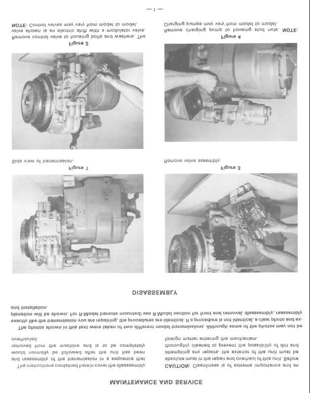
34 Figure 5 Remove charging pump assembly. Figure 8 Remove pump adaptor bolts and pump adaptor. (Adaptors may vary.) NOTE: The following converter disassembly was taken with a long drop transmission. Disassembly of the converter is identical on long and short drop transmissions. Figure 6 Remove pressure regulating valve assembly. Figure 9 Remove impeller cover bearing cap bolts Figure 10 Remove impeller cover bearing cap. 2


35 Remove impeller cover bolts. Figure 14 Remove impeller cover bearing snap ring and spacer. Separate impeller cover and turbine. Figure 12 Install aligning stud. Use pry slots to remove cover. Figure 15 Remove reaction member retainer ring. Figure 13 Remove impeller cover and turbine as an assembly. Figure 16 Remove reaction member and spacer. 3


36 Figure 17 Remove converter housing to engine housing spacer ring. Figure 20 Remove impeller assembly. Figure 18 Remove oil baffle retainer ring. Figure 21 Remove stator support to housing bolts. Figure 19 Using pry slots in converter housing, pry oil baffle and impeller from housing. NOTE: Impeller, oil baffle and impeller hub gear are removed as an assembly. Figure 22 Remove stator support. NOTE: Support must be turned to clear pump drive gear. 4


37 Figure 23 Remove converter housing to transmission housing bolts. Figure 26 Move center gear toward the rear of converter housing. Remove pump drive gear on the right. Figure 24 Support converter housing with chain tall and separate from transmission housing. Figure 27 Remove pump drive gear an the left. Figure 25 Remove pump drive gear bearing support bolts. 5 Figure 28 Remove center pump drive gear.


 Figure 33 Remove output flange.")
38 Figure 29 Use a spreading type snap ring pliers to spread the ears on forward clutch front bearing retainer ring. Remove forward clutch with pry bar. Figure 32 Remove output flange nut, washer and "0" ring. Figure 30 Remove converter to transmission spacer. (Used with 12 plate modulated clutches only.) Figure 33 Remove output flange. Figure 31 Remove 2nd clutch pilot bearing. Figure 34 Remove low clutch bearing cap. Note oil sealing ring. 6


39 Figure 35 Remove output shaft bearing cap. Figure 38 Remove output shaft and low clutch rear bearing locating ring. Cut and remove low clutch rear bearing retainer plate bolt lockwire. Remove low clutch shaft oil sealing ring. Figure 39 Remove rear cover bolts. Using pry slots provided, pry cover from transmission housing tapping on low clutch and output shaft to allow cover to be removed without shaft binding. NOTE: The use of alignment studs will facilitate cover removal. Figure 37 Remove retainer plate bolts and plate. Figure 40 Remove bearing lock balls. 7


 or the outer cage and rollers may be pulled trom the bearing inner")
40 Figure 41 Remove low clutch double bearing cup, outer cone bearing and spacer. Figure 43-A A Timken bearing cup, No must be used with the above bearing puller. Figure 42 CAUTION: Outer cone bearing, double bearing cup, spacer and inner cone bearing are replaced as a set only. Figure 44 Remove 2nd gear ring retainer snap ring. Figure 43 Remove low clutch inner bearing cone. NOTE: To remove the inner cone bearing without damage. a special bearing pulier must be made (see diagram Fig. 43-A) or the outer cage and rollers may be pulled trom the bearing inner race and the inner race can be removed after the low clutch assembly has been removed trom the transmission. See caution in Figure 42. Figure 45 Remove 2nd gear retainer ring retainer. 8

 Figure 46 Remove 2nd gear")


41 Figure 48 Remove output shaft assembly. (3 speed output shaft shown.) Figure 46 Remove 2nd gear retainer ring. Figure 49 Remove low speed drive gear retainer ring and drive gear. Figure 47 Remove 2nd gear. NOTE: On the 4 speed transmission there is a bearing end plate between the 2nd gear and bearing. Figure 50 Remove reverse and 3rd clutch assembly. Figure 51 Remove low clutch assembly.


42 Figure 52 Remove impeller hub gear retainer ring. Figure 55 Remove impeller to hub bolts. Figure 53 Remove impeller hub gear. Figure 56 Remove impeller hub, "0" ring and impeller hub screw backing ring. Figure 56 CLUTCH DISASSEMBLY NOTE: Each disc spring assembly is made up of selected springs to precisely match each part within this assembly. Failure to replace all piston return springs can result in unequal deflection within the spring pack. The result of this imbalance may adversely affect overall life of springs. The disc spring packs are to be used as complete assemblies and care should be taken not to intermix the individual disc springs with disc springs in another clutch or disc spring pack. Figure 54 Lift oil baffle and oil seal assembly from impeller. NOTE: DO NOT MIX THE FRICTION DISC IN THE LOW CLUTCH WITH THE FRICTION DISCS OF ANY OF THE OTHER CLUTCHES. (SEE NOTE FOLLOWNG FIGURE 104). 10


43 LOW CLUTCH DISASSEMBLY Figure 57 Remove low clutch shaft front bearing race. Figure 60 Remove low speed gear and outer taper bearing. Remove low clutch taper bearing spacer. Figure 58 Remove low speed gear taper bearing retainer ring retainer. Figure 61 Remove clutch end plate retainer ring. Remove clutch end plate and inner and outer clutch discs. Figure 59 Remove low speed gear taper bearing retainer ring. Figure 62 Remove low gear inner taper bearing. 11


![Sleeve shown is a common pipe, with a 1-1/2 x 1 [39,0 x 26,0 mm] opening.](/docs-images/72/68075925/images/44-4.jpg "The pipe is 6 x 3-1/4 x 2-3/4 [155,0 x 85,0 x 78,0 mm]. Compress disc springs washer.")

44 (Forward being disassembled) Forward and 2nd clutch and reverse and 3rd clutch disassemble and reassemble the same except forward and reverse clutches use disc springs for the piston return and the 2nd and 3rd clutches use a spring for the piston return. NOTE: If forward and reverse clutches are non-modulated, they will also use a spring for piston return instead of disc springs. Remove snap ring, ring retainer. Figure 66 Remove clutch shaft piston rings and expander springs. See page 67 for proper piston ring and expander spring installation. Figure 64 Remove clutch piston return disc spring retainer ring. A sleeve with a portion removed is recommended for removing the clutch piston return spring washers and retainer ring. Sleeve shown is a common pipe, with a 1-1/2 x 1 [39,0 x 26,0 mm] opening. The pipe is 6 x 3-1/4 x 2-3/4 [155,0 x 85,0 x 78,0 mm]. Compress disc springs washer. Through opening, remove retainer ring. Release tension on washers. Remove spring retainer ring. Figure 67 Remove front bearing retainer ring. Figure 65 Remove disc springs and spacer. Turn clutch over and tap clutch shaft on a block of wood to remove clutch piston. NOTE: Disc springs in the low clutch are different than disc springs in the forward and reverse clutch. Do not mix low clutch springs with forward and reverse springs. See page 40 for spring identification. Figure 68 Remove spacer and bearing. Caution: Do not lose lock ball. 12 FORWARD AND 2ND CLUTCH DISASSEMBLY


45 Figure 69 Pry front bearing inner race from shaft. Caution: Do not damage bearing roller surface. Figure 72 Remove clutch driven gear and outer bearing, Figure 70 Remove front bearing locating ring. Figure 73 Remove end plate retainer ring. Figure 71 Pry gear up to accommodate gear puller. 13 Figure 74 Remove end plate.


46 Figure 75 Remove inner and outer clutch discs. Figure 78 Compress spring retainer washer. Through opening remove spring retainer snap ring. Release tension on spring retainer. Figure 79 Remove snap ring and snap ring retainer. Figure 76 Remove inner bearing. Figure 80 Remove disc spring washers. NOTE: Non-modulated clutches will have a piston return spring in forward & reverse. See note in Figure 65. Figure 77 Remove hearing locating ring. 14

47 INSPECTION The importance of careful and thorough inspection of all parts cannot be overstressed. Replacement of all parts showing indication of wear or stress will eliminate costly and avoidable failures at a later date. BEARINGS Carefully inspect all rollers; cages and cups for wear, chipping or nicks to determine fitness of bearings for further use. Do not replace a bearing cone or cup individually without replacing the mating cup or cone at the same time. After inspection, dip bearings in Automatic Transmission Fluid and wrap in clean lintless cloth or paper to protect them until installed. Figure 81 Remove clutch piston. CAUTION: Care should be exercised to avoid skin rashes. fire CLEANING Clean all parts thoroughly using solvent type cleaning fluid. It is recommended that parts be immersed in cleaning fluid and moved up and down slow I y until all old lubricant and foreign material is dissolved and parts are thoroughly cleaned. hazards and inhalation of vapors when using solvent type cleaners. BEARINGS Remove bearings from cleaning fluid and strike flat against a block of wood to dislodge solidified particles of lubricant. Immerse again in cleaning fluid to flush out particles. Repeat above operation until bearings are thoroughly clean. Dry bearings using moisture-free com- pressed air. Be careful to direct air stream across bearing to avoid spinning. Do not spin bearings when drying. Bearings may be rotated slowiy by hand to facilitate drying process. HOUSINGS CLEANING AND INSPECTION Clean interior and exterior of housings, bearing caps, etc. thoroughly. Cast parts may be cleaned in hot solution tanks with mild alkali solutions providing these parts do not have ground or polished surfaces. Parts should remain in solution long enough to be thoroughly cleaned and heated. This will aid the evaporation of the cleaning solution and rinse water. Parts cleaned in solution tanks must be thoroughly rinsed with clean water to remove all traces of alkali. Cast parts may also be cleaned with steam cleaner. OIL SEALS, GASKETS, Etc. Replacement of spring load oil seals, "0" rings, metal sealing rings, gaskets and snap rings is more economical when unit is disassembled than premature overhaul to replace these parts at a future time. Further loss of lubricant through a worn seal may result in failure of other more expensive parts of the assembly. Sealing members should be handled carefully, particularly when being installed. Cutting, scratching, or curling under of lip of seal seriously impairs its efficiency. Apply a thin coat of Permatex No.2 on the outer diameter of the oil seal to assure an oil tight fit into the retainer. When assembling new metal type sealing rings, same should be lubricated with coat of chassis grease to stabilize rings in their grooves tor ease of assembly of mating members. Lubricate all "0" rings and seals with recommended type Automatic Transmission Fluid before assembly. GEARS & SHAFTS If magna-flux process is available, use process to check parts. Examine teeth on all gears carefully for wear, pitting, chipping, nicks, cracks or scores. If gear teeth show spots where case hardening is worn through or cracked, replace with new gear. Small nicks may be removed with suitable hone. Inspect shafts and quills to make certain they are not sprung, bent, or splines twisted, and that shafts are true. HOUSING. COVERS. etc. Inspect housings, covers and bearing caps to be certain they are thoroughly clean and that mating surfaces, bearing bores, etc., are tree from nicks or burrs. Check all parts carefully for evidence of cracks or condition which would cause subsequent oil leaks or failures. CAUTION: Care should be exercised to avoid inhalation of vapors and skin rashes when using alkali cleaners. AII parts cleaned must be thoroughly dried immediately by using moisture-free compressed air or soft, lintless absorbent wiping rags tree of abrasive materials such as metal filings, contaminated oil or lapping compound. 15


48 FORWARD AND 2nd CLUTCH REASSEMBLY (Forward being assembled) Figure 82 Install new clutch piston inner and outer sealing rings. Figure 85 Install 2nd disc spring washer with large diameter of bevel up. Install balance of washers, quantity (1) seven alternating bevel. Figure 83 Insert clutch piston in clutch drum. CAUTION: Do not damage sealing rings. See note in Figure 80. Figure 86 Install disc spring snap ring retainer and snap ring. Compress washers and snap ring retainer, install snap ring in lower snap ring groove. Install bearing locating ring. See page 40, Figure A. Figure 84 Install 1 st disc spring washer, large diameter of bevel down as shown. NOTE: Do not mix forward clutch disc spring washers with low clutch washers. See NOTE in Figure 65. Figure 87 Insert one steel disc. 16


49 Figure 88 Install one friction disc. Alternate steel and friction discs until the proper amount of discs are installed. First disc next to the piston is steel, last disc installed is friction. Figure 91 Install clutch driven gear inner bearing. NOTE: The inner bearing does not have a bearing shield. Figure 89 Install end plate. Figure 92 Install clutch driven gear into clutch drum. Align splines on clutch gear with internal teeth of friction discs. Tap gear into position. Do not force this operation. Gear splines must be in full position with internal teeth of all friction discs. Figure 90 Install end plate retainer ring. Figure 93 Install driven gear outer bearing. NOTE: Bearing shield in. See page


50 Figure 94 Install front bearing locating ring. Figure 97 Install lock bali and bearing spacer. Figure 95 Install front bearing inner race. Figure 98 Install hearing retainer ring. Figure 96 Install front bearing and outer race. 18 Figure 99 Install piston rings and expander springs as explained on page 67.


 five washers. See page 40, Figure C. Figure 104 Install low gear inner taper bearing. Install one steel disc. Install one friction disc.")

51 FORWARD & REVERSE NON-MODULATED CLUTCHES AND 2nd & 3rd CLUTCH PISTON RETURN SPRING REASSEMBLY Figure 102 Position piston return disc spring washer snap ring. Compress washers and install snap ring. Figure 100 Install new clutch piston inner and outer sealing ring. Insert piston into clutch drum using caution as not to damage seals. Position inner spring retainer, piston return spring, outer spring retainer and retainer snap ring retainer and snap ring. Compress spring and retainer and install snap ring. See page 40, Figure B. Assemble clutch discs and end plate as previously explained. LOW CLUTCH REASSEMBLY Figure 103 Install snap ring retainer. Figure 101 Install new clutch piston inner and outer sealing ring. Insert piston into clutch drum using caution as not to damage seals. Install piston to disc spring washer spacer. See NOTE in Figure 65. Install disc spring washers. First washer with large diameter of washer toward spacer. Alternate (5) five washers. See page 40, Figure C. Figure 104 Install low gear inner taper bearing. Install one steel disc. Install one friction disc. NOTE: The friction discs in the low clutch has 8 higher co-efficient rating than the friction discs in the other clutches, therefore the discs must not be mixed. The low clutch inner disc can be identified by an "X" stamped on one side of the inner teeth. The low clutch inner disc also has a strip of non-soluble yellow paint sprayed on the outer edge of the disc. Alternate steel and friction discs until the proper amount of discs are installed. First disc next to the piston is steel, last disc installed is friction. 19


52 Figure 105 Install end plate and retainer ring. Figure 108 Install low gear outer taper bearing. Figure 106 Install low clutch taper bearing spacer. NOTE: When installing the 3rd gear in the 3rd speed clutch a bearing spacer is used between the inner and outer 3rd gear bearing also. Figure 109 NOTE: Retainer ring is selected at assembly for proper thickness. A snap ring kit is available. Select the thickest of the three rings in the kit that can be fitted into the snap ring groove to assure s proper taper bearing tightness. Check ring as shown for tight ring to bearing fit. Figure 107 Install low gear into crutch drum. Align splines on low gear with internal teeth of friction discs. Tap gear into position. Do not force this operation. Gear splines must be in full position with internal teeth of all friction discs. 20 Figure 110 Install low clutch taper bearing retainer ring.


53 Figure 111 Install low speed gear taper bearing retainer ring retainer. Figure 114 Install low clutch assembly from rear of transmission case. Figure 112 Install low clutch shaft front bearing inner race with large diameter of race down. Figure 115 Install reverse and 3rd clutch assembly from the front of the transmission. Figure 113 Install low clutch front bearing. Roller bearing on 4 speed transmission and a ball bearing on the 3 speed transmission. Figure 116 Install low speed drive gear and retainer ring. 21


54 Figure 117 Press output gear on output shaft. Install output gear washer in undercut of gear. (3 speed shown). Figure 120 Install output shaft assembly in housing. (3 speed shown). See caution in Figure 42. Figure 118 Press inner taper bearing on output shaft. Insta!! double taper bearing spacer, double taper bearing cup and outer taper bearing. (3 speed shown). Figure 121 Install low clutch inner taper bearing. NOTE: Heat bearing in hot oil prior to installation. Figure 119 Output shaft assembly. (3 speed shown). Figure 122 Install bearing spacer and double bearing cup. 22


55 Figure 123 Install outer taper bearing. NOTE: Heat bearing in hot oil prior to installation. Figure 126 Install low clutch shaft oil sealing ring. Figure 124 Install bearing retainer plate, inner diameter chamfer toward bearing. Figure 127 Install alignment studs and new gasket. Place lock balls in low shaft and idler shaft. A light coat of grease will hold lock balls in place. Position shafts so lock balls align with notches in rear cover. Figure 125 Install bolts. block gears to prevent turning. Tighten bolts to specified torque. Lockwire bolts to prevent loosening. 23 Figure 128 Tap cover in place and secure with bolts and lockwashers.


56 Figure 129 Tighten cover bolts to specified torque. Figure 132 Install new "0" ring and gasket on low clutch bearing cap. Position cap over clutch shaft, use caution as not to damage oil sealing ring. Figure 130 Install the output shaft and low clutch shaft rear bearing locating ring. Be certain ring is in full position in ring groove. Figure 133 Install bolts and washers, tighten to specified torque. Figure 131 Coat outer diameter of oil seal with Permatex No.2 and press seal in the output shaft bearing cap with lip of seal in. Position new gasket on bearing cap. Install bearing cap on transmission housing. Install bolts and lockwashers, tighten to specified torque. Figure 134 Install output flange on output shaft. 24


57 Figure 135 Install the output flange "0" ring, washer and flange nut. Block output flange to prevent from turning. See elastic stop nut torque chart, Figure H. Figure 138 Install 2nd speed gear retaining ring retainer. Figure 139 Install 2nd gear ring retainer snap ring. Figure 136 Install 2nd speed gear on low clutch shaft. NOTE: The 4 speed transmission has a bearing end plate between the 2nd gear and bearing. Figure 140 Install transmission case gasket and "0" rings. Install housing spacer. NOTE: Housing spacer is used with 12 plate clutch modulation only. Figure 137 Install 2nd speed gear retainer ring. 25
 impeller hub special screws to approximately.06 inch [1,5] of seated position.")
![With a calibrated torque wrench, tighten screws to 40-45 Ibs. ft. [54,3-61,0 N.m] torque.](/docs-images/72/68075925/images/58-1.jpg "NOTE: Assembly of impeller to impeller hub must be completed within a fifteen minute period from start of screw installation.")


58 Figure 141 Install housing spacer gasket and "0" rings. See R-Model section for front cover installation. Figure 144 Install (12) impeller hub special screws to approximately.06 inch [1,5] of seated position. With a calibrated torque wrench, tighten screws to Ibs. ft. [54,3-61,0 N.m] torque. NOTE: Assembly of impeller to impeller hub must be completed within a fifteen minute period from start of screw installation. The screws are prepared with coating which begins to harden after installation in the impeller hub holes. If not tightened to proper torque within the fifteen minute period, insufficient screw clamping tension will result. The special screw is to be used for one installation only. If the screw is removed for any reason it must be replaced. The compound left in the hub holes must be removed with the proper tap and cleaned with solvent. Dry hole thoroughly and use a new screw for reinstallation. Figure 142 Clean impeller hub mounting surface and tapped holes with solvent. Dry thoroughly being certain tapped holes are dry and clean. Install new "0" ring on impeller hub. Position impeller hub screw backing ring. Figure 145 Apply a light coat of Permatex No.2 on the outer diameter of the oil baffle seal. Press seal in oil baffle with lip of seal down. (NOTE: When baffle is positioned on impel!er. lip of oil seal wil! be up.) Figure 143 Align holes in impeller hub with holes in impeller and backing ring. 26


59 Figure 146 Install a new oil baffle seal ring. Figure 149 Secure impeller hub gear with retainer ring. Figure 150 Install new turbine shaft piston ring. Figure 147 Install oil baffle on impeller assembly. See Note in Figure 145. DRIVE GEAR RETAINING RING TURBINE SHAFT NOTE: LONG HUB OF DRIVE GEAR TOWARD RETAINER RING Figure 148 Install impeller hub gear. Figure 151 Tap turbine shaft and bearing assembly into converter housing from front. At the rear of the converter housing install turbine shaft gear and retainer ring as shown. 27


60 Figure 152 Support converter housing with chain faji. Spread forward clutch front bearing retainer ring and tap fo~ard and 2nd clutch assembly into transmission case assembly. Be certain snap ring is in full position in ring groove. Figure 155 Install right pump drive gear. Figure 153 Position center pump drive gear. Figure 156 Align holes in pump drive gear bearing supports with holes in converter housing. Install bolts and washers and tighten to specified torque. Figure 154 Install left pump drive gear. Figure 157 Install 2nd speed clutch pilot bearing. 28


61 Figure 158 Install alignment studs and position converter housing on studs. NOTE: Turn output shaft to align clutch disc hub in clutch. Do not force this operation. Figure 161 Install stator support bolts and tighten to specified torque. Figure 159 NOTE: Bolts are not to be used to pull converter housing to Install converter housing to transmission housing bolts and tighten to specified torque. transmission housing. Figure 162 Grease stator support piston ring, oil baffle oil seal and seal ring to facilitate reassembly. Install impeller and oil baffle assembly in converter housing. Figure 160 Install new sealing ring expander spring and oil sealing ring on support. NOTE: Expander spring gap to be 180 from sealing ring hook joint. Position support on turbine shaft, turn support to clear pump drive gear. Align support holes with converter housing. Figure 163 Position oil baffle in housing. Secure with oil baffle retainer ring, being sure ring is in full position in ring groove 29


62 Figure 164 Install reaction member spacer with tang facing out. Install reaction member. Install spacer and turbine to impeller cover bearing snap ring. Figure 165 Install reaction member retainer ring. Figure 168 Position new impeller to impeller cover "0" ring on impeller. Install turbine and impeller cover. Figure 166 Position turbine in impeller cover. Figure 169 Install impeller cover bolts and torque to specifications. Figure


63 Figure 170 Install new "0" ring seal in impeller cover bearing cap. Figure 171 Install bearing cap and bolts, torque to specifications. Figure 174 Position a new gasket and "0" rings on the pressure regulating valve. Install valve assembly on studs. Figure 172 Position auxiliary pump adaptor on housing. Install adaptor bolts and washers, tighten to specified torque. (Adaptors may vary.) Figure 175 Install pump assembly on studs. NOTE: Pump assemblies may vary. 31


64 Figure 176 Tighten pump stud nuts to specified torque. Control valve assemblies may vary. The one shown being assembled on converter housing is an electric valve with modulated shift. Figure 179 Position valve plate to control valve gasket and control valve on studs. The use of aligning studs will facilitate valve to housing assembly. Figure 177 Position a new modulator to housing gasket and modulator valve assembly on aligning studs. Figure 180 Position new control valve to solenoid valve housing gasket and solenoid housing on studs. Figure 178 Position modulator valve opening plate gasket and plate on studs. Figure 181 Install control valve assembly to converter housing bolts and washers. Tighten to specified torque. 32

65 Figure 182 Install converter housing to engine flywheel housing spacer. NOTE: IF TRANSMISSION HOUSING OR CONVERTER HOUSING WAS REPLACED SEE PAGE 55 FOR SPEED SENSOR BUSHING INSTALLATION. 33


66 SERVICING MACHINE AFTER TRANSMISSION OVERHAUL The transmission, torque converter, and its allied hydraulic system are important links in the drive line between the engine and the wheels, The proper operation of either unit depends greatly on the condition and operation of the other; therefore, whenever repair or overhaul of one unit is performed, the balance of the system must be considered before the job can be considered completed. After the overhauled or repaired transmission has been installed in the machine, the oil cooler, and connecting hydraulic system must be thoroughly cleaned. This can be accomplished in several manners and a degree of judgment must be exercised as to the method employed. The following are considered the minimum steps to be taken: 1. Drain entire system thoroughly. 2. Disconnect and clean all hydraulic lines, Where feasible, hydraulic lines should be removed from machine for cleaning. 3. Replace oil filter elements, cleaning out filter cases thoroughly, 4. The oil cooler must be thoroughly cleaned, The cooler should be "back flushed" with oil and compressed air until all foreign material has been removed. Flushing in direction of normal oil flow will not adequately clean the cooler, If necessary, cooler assembly should be removed from machine for cleaning, using oil, compressed air and steam cleaner for that purpose, DO NOT use flushing compounds for cleaning purposes. 5, On remote mounted torque converters remove drain plug from torque converter and inspect interior of converter housing, gears, etc, If presence of considerable foreign material is noted, it will be necessary that converter be removed, disassembled and cleaned thoroughly. It is realized this entails extra labor; however, such labor is a minor cost compared to cost of difficulties which can result from presence of such foreign material in the system. 6. Reassemble all components and use only type oil recommended in lubrication section. Fill transmission through filler opening until fluid comes up to LOW mark on transmission dipstick. NOTE: If the dipstick is not accessible oil level check plugs are provided. Remove LOWER check plug, fill until oil runs from LOWER oil hole. Replace filler and level plug. Run engine two minutes at RPM to prime torque converter and hydraulic lines. Recheck level of fluid in transmission with engine running at idle ( RPM), Add quantity necessary to bring fluid level to LOW mark on dipstick or runs freely from LOWER oil level check plug hole. Install oil level plug or dipstick, Recheck with hot oil ( F.) [82, 2-93, 3 C], Bring oil level to FULL mark on dipstick or runs freely from UPPER oil level plug. 7, Recheck all drain plugs, lines, connections, etc., for leaks and tighten where necessary. TORQUE IN (LBS.-FT.) BOLTS, CAPSCREWS, STUDS AND NUTS Grade 5 Identification, 3 Radial Dashes 120 Apart on Head of Bolt Grade 8 Identification, 6 Radial Dashes 60 Apart on Head of Bolt LUBRICATED OR PLATED Grade 5 Grade 8 Nominal Fine Thread Course Thread Fine Thread Course Thread Size Torque Lbs. Ft./N.m. Torque Lbs. Ft./N.m. Torque Lbs. Ft./N.m. Torque Lbs. Ft./N.m [ ] [ ] [ ] [35.3-4O.7] [ ] [ ,9] [ ] [ ] [ ] [ ] [ ] [ ] [ ] [ ] [ ] 8O-88 [ ] [123, ] [ ] [ ] [
67 SPECIFICATIONS AND SERVICE DATA-POWER SHIFT TRANSMISSION AND TORQUE CONVERTER CONVERTER OUT Converter outlet oil temp F PRESSURE 182,3 933 C]. Transmission in NEUTRAL. Operating specifications 25 PS" 1172,4 kpal minimum pressure at 2000 RPM engine speed AND a maximum of 70 PSI 1482,6 kpal outlet pressure with engine operating at no load governed speed CONTROLS Forward and Reverse Manual Speed Selection Manual CLUTCH TYPE Multiple discs, hydraulically actuated spring released automatic wear compensation and no adjustment All clutches oil cooled and lubricated CLUTCH INNER DISC Friction CLUTCH OUTER DISC Steel OIL FILTRATION Full flow oil filter safety by-pass, also strainer screen in sump at bottom of transmission case. CLUTCH PRESSURE psi [1654,8 2068,4 kpa] With parking brake set (see note) oil temperature 180 o 200 o F Ci, engine at idle 1400 to 600 RPM). shift thru direction and speed clutches All clutch pressure must be equal within 5 psi kpa" If clutch pressure varies in anyone clutch more than 5 psi kpal repair clutch NOTE. Never use service brakes while making clutch pressure checks Units having brake actuated declutching in forward and/or reverse will not give a true reading. ALWAYS USE PARKING BRAKE WHEN MAKING CLUTCH PRESSURE CHECKS LUBRICATION TYPE OF OIL CAPACITY CHECK PERIOD NORMAL * DRAIN PERIOD See Lube Chart. Consult Operator's Manual on applicable machine model for system capacity. Torque Converter, Transmission and allied hydraulic system must be considered as a whole to determine capacity. Check oil level DAILY with engine running at RPM and oil at 180 to 200 F [82, 2 93, 3 C]. Maintain oil level to FULL mark. Every 500 hours, change oil filter element. Every 1000 hours, drain and refill system as follows: Drain with oil at 150 to 200 F. [65,6-93,3 C]. NOTE: it is recommended that filter elements be changed after 50 and 100 hours of operation on new and rebuilt or repaired units. (a) Drain transmission and remove sump screen.clean screen thoroughly and replace, using new gaskets. (b) Drain oil filters, remove and discard filter elements. Clean filter shells and install new elements. (c) Refill transmission to LOW mark. (d) Run engine at RPM to prime converter and lines. (e) Recheck level with engine running at RPM and add oil to bring level to LOW mark. When oil temperature is hot ( F.) [82,2-93,3 C] make final oil level check. BRING OIL LEVEL TO FULL MARK RECOMMENDED LUBRICANTS FOR CLARK-HURTH COMPONENTS POWER SHIFTED TRANSMISSION AND TORQUE CONVERTERS Prevailing Ambient Temperature.*Dexron is a registered trademark of General Motors Corp. (a) C2 Grade 30 Temperature (b) C3 Grade 30 Range1 (c) Engine Oil Grade 30 AP-CD/SE or CD/SF (d) MILL2104C Grade30 (e) MILL2104DGrade 30 (a) MILL2104C Grade 10 (b) MILL2104D Grade 10 Temperature (C) C2 Grade 10 Range 2 (d) C3 Grade 10 Temperature (e) Engine Oil Grade 10 AP-CD/SE or CD/SF (f) Quintolubric (Non Phosphate Ester Fire Resistant Fluid) (a).*dexron Range 3 (b).*dexron II D See Caution Below Temperature Range 4 (a) MILL46167 (b) MILL46167 A Temperature (a) Conoco High Performance Synthetic Motor Oil - Range 5 Spec No 6718 PREFERRED Oil VISCOSITY Select highest oil viscosity compatible with prevailing ambient temperatures and oil application chart Temperature ranges 2" and "3" may be used to lower ambient temperatures when sump preheaters are used Temperature range "4" should be used only in ambient temperature range shown MOOULATED SHIFT TRANSMISSIONS T & series transmissions with modulated shift use only C-3 0, temperature range 3 items (a) & (b) *Dexron D *Dexron II D SEE CAUTION BELOW & series transmissions with modulated shift use only C3 D, temperature range 3 item (a) only *Oexron D Do NOT use *Dexron II D SEE CAUTION BELOW CAUTION *Dexron II D is not compatible with graphitic clutch plate friction material UNLESS IT MEETS THE APPROVED C-3 SPECIFICATIONS. *Dexron II D cannot be used in the , or series powershift transmissions. or the HR28000 & HR32000 series having converter lock-up. or the C270 series converter having lock-up UNLESS IT MEETS THE APPROVED C3 SPECIFICATIONS. Any deviation from this chart must have written approval from the application department of the Spicer Off-Highway Engineering and Marketing Department * Normal drain periods and filter change intervals are for average environmental and duty-cycle conditions. Severe or sustained high operating temperatures or very dusty atmospheric conditions will cause accelerated deterioration and contamination. For extreme conditions judgment must be used to determine the required change intervals. 35
68 TROUBLE SHOOTING GUIDE For The R and HR Model, Transmission The following data is presented as an aid to locating the source of difficulty in a malfunctioning unit. It is necessary to consider the torque converter charging pump, transmission, oil cooler, and connecting lines as a complete system when running down the source of trouble since the proper operation of any unit therein depends greatly on the condition and operations of the others. By studying the principles of operation together with data in this section, it may be possible to correct any malfunction which may occur in the system. TROUBLE SHOOTING PROCEDURE BASICALLY CONSISTS OF TWO CLASSIFICATIONS: MECHANICAL AND HYDRAULIC. MECHANICAL CHECKS Prior to checking any part of the system from ii hydraulic standpoint, the following mechanical checks should be made: 1. A check should be made to be sure that the control lever linkage is properly connected and adjusted at all connecting points. 2. Check shift levers and rods for binding or restrictions in travel that would prevent full engagement. Shift levers by hand at control valve, if full engagement cannot be obtained, difficulty may be in control cover and valve assembly. HYDRAULIC CHECKS Before checking on the torque converter, transmission, and allied hydraulic system for pressures and rate of oil flow, it is essential that the following preliminary checks be made: Check oil level in transmission. This should be done with oil temperatures of 180 to 200 F. [82,2-93,3 C]. DO NOT ATTEMPT THESE CHECKS WITH COLD OIL. To bring the oil temperature to this specification it is necessary to either work the machine or "stall" out the converter. Where the former means is impractical, the latter means should be employed as follows: Engage shift levers in forward and high speed and apply brakes. Accelerate engine half to three-quarter throttle Hold stall until desired converter outlet temperature is reached. CAUTION: FULL THROTTLE STALL SPEEDS FOR AN EXCESSIVE LENGTH OF TIME WILL OVERHEAT THE CONVERTER. LOW CLUTCH PRESSURE Cause 1. Low oil level. 2. Clutch pressure regulating valve spool stuck open. 3. Faulty charging pump. 4. Broken or worn clutch shaft or piston sealing rings. 5. Clutch piston bleed valve stuck open. Remedy 1. Fill to proper level. 2. Clean valve spool and housing. 3. Replace pump. 4. Replace sealing rings. 5. Clean bleed valves thoroughly. LOW CONVERTER CHARGING PUMP OUTPUT 1. Low oil level. 2. Suction screen plugged. 3. Air leaks at pump intake hose and connections or collapsed hose. (R only) 4. Defective oil pump. 1. Fill to proper level. 2. Clean suction screen. 3. Tighten all connections or replace hose if necessary. 4. Replace pump. OVERHEATING 1. Worn oil sealing rings. 2. Worn oil pump. 3. Low oil level. 4. Pump suction line taking air. (R only) 1. Remove, disassemble, and rebuild converter assembly. 2. Replace. 3. Fill to proper level. 4. Check oil line connections and tighten securely. NOISY CONVERTER 1. Worn coupling gears. 2. Worn oil pump. 3. Worn or damaged bearings. 1. Replace. 2. Replace. 3. A complete disassembly will be necessary to determine what bearing is faulty. LACK OF POWER 1. Low engine RPM at converter stall. 2. See "Overheating" and make same checks. 1. Tune engine check governor. 2. Make corrections as explained in "Overheating." 36
69 MODULATED VALVE ASSEMBLY ITEM DESCRIPTION QTY 1 Accumulator Valve Stop Plug Accumulator Valve Stop Plug "0" Ring Accumulator Spring Outer Accumulator Spring Inner Accumulator Valve Pin Accumulator Valve Plug... 2 ITEM DESCRIPTION QTY. 9 Regulator Spool Regulator Spring Regulator Spool Stop Plug "0" Ring Regulator Spool Plug Modulator Valve to Plate Gasket Housing Spacer Gasket Housing Spacer Modulator Valve Housing
70 38
71 THEORY OF OPERATION TRANSMISSION MODULATOR VALVE OPERATIONAL DESCRIPTION Both directional clutch assemblies are controlled by individual modulator valves. The pressure rise at side "A" of the regulator spool is the same as that applying the clutch piston. Supply flow to the clutch and modulator is limited by a flow limiting orifice. From this limited flow the regulator spool drains flow to the vent port. The regulator spool restricts flow through the vent port to build clutch pressure at a predetermined rate. Once the vent flow is shut off, only minimal flow passes through the flow limiting orifice to make up for normal spool and clutch leakages. Pressure on either side of the orifice is virtually identical and full regulated system pressure is applied at the clutch piston. When forward direction is selected the oil under pressure enters the port on the "A" side of the regulator spool. This passes through the dampening orifice. The pressure force on the spool area shifts the spool to the right exposing the vent port. The time required to shift the regulator spool over to expose the vent port shows up as a pressure spike at the beginning of the pressure versus time chart. The movement of the regulator spool is opposed by the regulator and accumulator springs. This provides an initial low pressure head of approximately 20 psi [137,9 Kpa] on the "A" side of the spool. This 20 psi [137,9 Kpa] is represented as a horizontal line on the pressure versus time chart immediately following the spike. Oil flows through the regulator spool orifice due to a pressure imbalance. Pressure at side "A" is constantly 10 psi [68,9 Kpa] higher than side "B" as a result of the added force of the side "B" spring, The 10 psi [68,9 Kpa] supply through the regulator spool orifice gives a controlled flow rate. This controlled flow establishes the time it takes to fill the accumulated cavity. As the accumulator cavity is filled, the accumulator spool is forced against the accumulator springs. As the springs compress their force increases causing the hydraulic pressure in the accumulator cavity and "B" side of the regulator spool to increase. Pressure on the "A" side of the regulator spool increases with the opposing force on the "B" side. This causes the rising slope in the clutch pressure versus time chart. The rate of this rise is controlled by the accumulator spring force. Once the accumulator spool is stroked to its limit, pressure on "A" and "8" side of the regulator spool is balanced since no flow passes through the regulator spool orifice. The regulator spool spring pushes the regulator spool to the left shutting off the vent flow. The clutch and modulator pressure rapidly rise to the system regulated clutch supply pressure setting. This is the vertical line on the clutch pressure versus time chart. The entire modulator sequence of events occurs in less than two seconds. The steady rise of clutch pressure increases the clutch driving torque which results in a smooth clutch application. When forward direction is selected the reverse clutch and modulator are vented through the control valve to the transmission sump. The reverse accumulator cavity is vented back through the regulator spool orifice. To hasten the reset time of the accumulator, immediately preparing the transmission for a directional shift, full system regulated clutch supply pressure from the forward control valve is directed to the spring cavity of the reverse accumulator. When reverse direction is selected the reverse clutch and modulator function through the same sequence of events as the forward clutch and modulator. This same sequence of events also applies to the lock-up modulators. 39
72 FIG.A [ ] MODULATED FWD. & REV. CLUTCHES FIG.B { 2nd & 3rd & NONMODULATED FORWARD & REVERSE CLUTCHES FIG.C [ ] LOW (1st) CLUTCH FIG.D (4 SPEED ONLY) 40
73 16 SCREW RING GEAR INSTALLATION PROCEDURE (Non-Asbestos Ring Gear) 1. Remove all burrs from flywheel mounting face and pilot bores. Clean the torque converter ring gear flywheel mounting surface and the ring gear screw tapped holes with solvent. Dry thoroughly, being certain ring gear screw holes are dry and clean. 2. Check engine flywheel and housing or housing adaptor for conformance to standard S.A.E. No.3 -SAE J927 and J1033 tolerance specifications for pilot bores size, pilot bores eccentricities and mounting face deviations. Measure and record engine crankshaft end play. 3. Install torque converter ring gear as shown. NOTE; Assembly of the ring gear must be completed within a fifteen minute period from start of screw installation. The screws are prepared with an epoxy coating which begins to harden after installation in the flywheel mounting holes. If not tightened to proper torque within the fifteen minute period insufficient screw clamping tension will result. 4 Install backing ring and sixteen (16) special screws to approximately 06 inch 11,5 mm 1 of seated position It is permissible to use a power wrench for this installation phase. With a calibrated torque wrench tighten screws 30 to 33 pounds feet of torque [40, 7 44,7 Nm]. To obtain maximum effectiveness of the special screw's locking feature, a minimum time period after screw installation of twelve (121 hours is suggested before engine start-up The special screw is to be used for ONE installation only If the screw is removed for any reason it MUST BE REPLACED It is recommended that the epoxy left in the flywheel hole be removed with the proper tap and cleaned with solvent. Dry hole thoroughly and use a NEW screw for re-installation 5 Assemble torque converter to engine flywheel by sliding converter into position by hand before fastening housing attachment screws This may require more than one trial to match the drive gear teeth Pulling the converter into position with housing attachment bolts is not recommended. 6 Measure engine crankshaft end play after assembly of torque converter This value must be within one thousandth (.001) of an inch mm] of end play recorded (in Paragraph #21 before assembly of torque converter INCH [38-1] 16 SCREW RING GEAR KIT Torque Converter Ring Gear RingGearScrew15lnch l38, Installation Instruction Sheet INCH SCREW RING GEAR KIT Torque Converter Ring Gear Ring Gear Screw 15 Inch 138, Backing Ring Installation Instruction Sheet Backing Ring not included in Ring Gear Kit Must be Ordered Separately Dimensions are in inches Dimensions in [ ] are mm SEE PAGE 42 FOR INSTALLATION ILLUSTRATIONS SEE PAGE 56 FOR 32 SOL T INSTALLATION 41
74 42

75 SHIELDED BEARING INSTALLATION 43
76 IMPELLER HUB & TURBINE HUB ASSEMBLY WITH BACKING RING AND SPECIAL SELF LOCKING SCREWS. 1. CLEAN HUB MOUNTING SURFACE AND TAPPED HOLES WITH SOLVENT. DRY THOROUGHLY BEING CERTAIN TAPPED HOLES ARE DRY AND CLEAN. 2. INSTALL BACKING RING AND SPECIAL SCREWS TO APPROXIMATELY.06 INCH [1,5] OF SEATED POSITION. WITH A CALIBRATED TORQUE WRENCH, TIGHTEN SCREWS 40 TO 45 LBS. FT. TORQUE [54,3-61,0 N.m]. NOTE: ASSEMBLY OF IMPELLER OR TURBINE HUB MUST BE COMPLETED WITHIN A FIFTEEN MINUTE PERIOD FROM START OF SCREW INSTALLATION THE SCREWS ARE PREPARED WITH A COATING WHICH BEGINS TO HARDEN AFTER INSTALLATION IN THE HUB HOLES IF NOT TIGHTENED TO PROPER TORQUE WITHIN THE FIFTEEN MINUTE PERIOD, INSUFFICIENT SCREW CLAMPING TENSION WILL RESULT. THE SPECIAL SCREW IS TO BE USED FOR ONE INSTALLATION ONLY. IF THE SCREW IS REMOVED FOR ANY REASON IT MUST BE REPLACED. THE COMPOUND LEFT IN THE HUB HOLES MUST BE REMOVED WITH THE PROPER TAP AND CLEANED WITH SOLVENT DRY HOLE THOROUGHLY AND USE A NEW SCREW FOR REINSTALLATION. 44
77 SPEED TRANSMISSION 45

")
78 32000 SERIES - 3 AND 4 SPEED CLUTCH & GEAR ARRANGEMENT (SHORT DROP OUTPUT) 46
79 SHORT DROP SERIES PLUMBING DIAGRAM (WITH REMOTE FILTER) 47
80 320OO 4 SPEED TRANSMISSION 48

81 Impeller Hub and Turbine Hub Assembly with Backing Ring and Special Self Locking Screws 1 Clean hub mounting surface and tapped holes with solvent Dry thoroughly being certain tapped holes are dry & clean 2 Install backing ring and special self locking screws. Tighten screws 40 to 45 Lbs Ft [54,3-61,0 N.m] Note Assembly of hub must be complete within a fifteen minute period from start of screw installation the special screw is to be used for one installation only If the screw is removed for any reason it must be replaced The epoxy left in the hub holes must be removed with the proper tap and cleaned with solvent Dry hole thoroughly and use a new screw for reinstallation Gear to be assembled with long hub length to this side Two clutches, 6-outer steel plates, 6-inner friction plates Assemble alternately, starting with outer steel plate See Elastic Stop Nut Torque Chart Low clutch,9-outer steel plates,9-inner friction plates. Assemble alternately, starting with outer steel plate Tighten oil screen assy 10 to 15 Lbs Ft [13,6-20,0 Nm] View "a" 2 Places Modulation only Low Clutch Return Springs. Concave side of first belleville washer to be placed against clutch piston. Remaining four washers to be stacked alternatelv reversed as shown Heat nose bushing to 200 FO (93 C) before assy. of bushing to cover Bearing shield out Must be loose internal fit bearings, No. "3" etched on bearing (12 Plate Modulation) Two clutches,12-outer steel plates,12-inner friction plates, Assemble alternately, starting with outer steel plate. Bearing shield in Notes A. -Use Permatex & Crane Sealer only where specified B -All lead in chamfers for oil seals, piston rings & "O" rings must be smooth & free from burrs Inspect at assy. C -Lubricate all piston ring grooves & "O" rings with oil before assy. D -Apply very light coat of Permatex No.2 to OD of all oil seals before assy E After assembly of parts using Permatex or Crane sealer, there must not be any free or excess material that could enter the oil circuit. F -Apply light coat of Crane Sealer to all pipe plugs. G -Apply a thin coating of grease between seal lips on lip type seals prior to assy H -Apply light coat of Permatex No 2 to all thru hole stud threads. NOTE. The friction discs in the low clutch has a higher co-efficient rating than the friction discs in the other clutches, therefore the discs must not be mixed. The low clutch inner disc can be identified byan "X" stamped on one side of the inner teeth The low clutch inner disc also has a strip of non-soluble yellow paint sprayed on the outer edge of the disc. View "R" Forward & Reverse Clutch Return Springs Concave side of first belleville washer tu be placed against clutch piston Remaining 3ix washers of each ciutch to be stacked alternately reversed as shown View "S" Enlarged view of Piston Ring & Expander Note. Expander gap to be approx. 180 from ring hook joint to aid ring assembly. NOTE: Metric dimensions shown In brackets [ ] THREAD SIZE LB-FT [Nm] 1" [ ,1] 1 1/4 " [271,2-338,9] 1 1/2 " [406,8-474,5] 1 3/4 " [ ,1] NOMINAL SIZE TORQUE SPECIFICATION FOR LUBRICATED OR PLATED SCREWS AND NUTS GRADE 5 GRADE 8 FINE THREAD COARSE THREAD FINE THREAD COARSE THREAD lbf.ft [N.m] lbf-ft [N.m] Ibf.-ft [N.m] Ibf-ft [N.m] [ [ r [ [22-27] [16-22] [38-43] [35-41] [35-39] [31.34] [50-56] [45-49] [ [ [ [ [87-95] [77-85] [ ] [ [ ] [ [ [ [ ] [ ] [ ] [ ] [ ) [ ] [ ] [ ]
82 4th SPEED CLUTCH DISASSEMBLY (4 Speed Transmission Only) SPEED TRANSMISSION 50


83 Figure 183 Remove clutch shaft oil sealing rings. Figure 186 Remove outer bearing. Figure 184 Remove front bearing retainer ring. Figure 187 Remove 4th gear outer bearing retainer ring. Figure 185 Pry front bearing to accommodate bearing puller. Figure 188 Pry 4th gear up to accommodate gear puller. Remove 4th gear. 51


84 4th SPEED CLUTCH REASSEMBLY Press output gear and clutch drum assembly on output shaft. Press output shaft gear spacer in undercut in output gear. Figure 189 Remove bearing spacer. Figure 192 Install piston. and piston return spring. See page 40. Fig. D. Install inner and outer discs as explained in Fig. 87 & 88. Install 4th speed gear inner bearing. NOTE: Bearing Part Number must go down. See Figure 195. Figure 190 Remove 4th gear inner bearing. Remove end plate retainer ring and end plate. Remove inner and outer clutch discs. Compress spring retainer washer. Remove spring retainer snap ring. Release tension on spring retainer. Remove snap ring, spring retainer, return spring and clutch piston. Figure 193 Install bearing spacer between inner and outer 4th speed gear bearings. Instal14th speed gear into clutch drum. Align splines on clutch gear with internal teeth of friction discs. Tap gear into position. Do not force this operation. Gear splines must be in full position with internal teeth of all friction discs. Figure 191 If rear bearing, shaft or output gear and clutch drum are to be replaced, press shaft from rear bearing and output gear. 52


85 Figure 194 Install 4th speed gear outer bearing. NOTE: Bearing Part Number must go up. See Figure 195. It is recommended a rubber band be used to hold outer bearing rollers in position when installing bearing. Figure 197 Install clutch shaft front bearing. Figure 195 Figure 198 Install bearing retainer ring. Figure 196 Install outer bearing retainer ring. Figure 199 Install clutch shaft oil sealing rings. 53

86 Figure 200 Install output shaft and 4th speed clutch assembly in transmission housing. Refer to Figure 121 for remainder of transmission reassembly. 54
87 REAR VIEW Assemble Speed Sensor Bushing in housing to specified dimension with Loctite 262 and stake (3) three places. SPEED SENSOR BUSHING INSTALLATION 55
88 32 SCREW RING GEAR INSTALLATION PROCEDURE (Non-Asbestos Ring Gear) 1. Remove all burrs from flywheel mounting face and pilot bores. Clean the torque converter ring gear flywheel mounting surface and the ring gear screw tapped holes with solvent. Dry thoroughly, being certain ring gear screw holes are dry and clean. 2. Check engine flywheel and housing or housing adaptor for conformance to standard S.A.E. No.3 -SAE J927 and J1033 tolerance specifications for pilot bores size, pilot bores eccentricities and mounting face deviations. Measure and record engine crankshaft end play. 3. Install torque converter ring gear as shown. NOTE: Assembly of the ring gear must be completed within a fifteen minute period from start of screw installation. The screws are prepared with an epoxy coating which begins to harden after installation in the flywheel mounting holes. If not tightened to proper torque within the fifteen minute period insufficient screw clamping tension will result. 4. Install backing ring and thirty-two (32) special screws to approximately.06 inch [1,5 mm] of seated position It is permissible to use a power wrench for this installation phase. With a calibrated torque wrench tighten screws 23 to 25 pounds feet of torque [31,2 33,8 N.m] To obtain maximum effectiveness of the special screw's locking feature, a minimum time period after screw installation of twelve (12) hours is suggested before engine start-up The special screw is to be used for ONE installation only If the screw is removed for any reason it MUST BE REPLACED. It is recommended that the epoxy left in the flywheel hole be removed with the proper tap and cleaned with solvent. Dry hole thoroughly and use a NEW screw for re-installation 5 Assemble torque converter to engine flywheel by sliding converter into position by hand before fastening housing attachment screws. This may require more than one trial to match the drive gear teeth Pulling the converter into position with housing attachment bolts is not recommended 6. Measure engine crankshaft end play after assembly of torque converter This value must be within one thousandth of an inch [0,0254mml of end play recorded (in Paragraph #2) before assembly of torque converter INCH [38.1] 32 SCREW RING GEAR KIT Torque Converter Ring Gear Ring Gear Screw 1.5 Inch [38, 1] Installation Instruction Sheet INCH [63.5] 32 SCREW RING GEAR KIT Torque Converter Ring Gear Ring Gear Screw 2.5 Inch [63,5] Installation Instruction Sheet INCH [44.4] 32 SCREW RING GEAR KIT Torque Converter Ring Gear Ring Gear Screw 175 Inch [44,4] Installation Instruction Sheet INCH [76.2] 32 SCREW RING GEAR KIT Torque Converter Ring Gear Ring Gear Screw 30 Inch [76,2] Installation, Instruction Sheet INCH [50,8] 32 SCREW RING GEAR KIT Torque Converter Ring Gear Ring Gear Screw 20 Inch [50,8] Installation Instruction Sheet M832 SCREW RING GEAR KIT Torque Converter Ring Gear Ring Gear Screw [M8 x 1 25] Installation Instruction Sheet Backing Ring Not Included in Ring Gear Kit Must be Ordered Separately NOTE: The initial installation drive gear mounting kit includes a converter air breather. This breather is used on C & CL 2701C & CL 320 converters only and is not required for the HR & LHR HR & LHR applications SEE PAGE 57 FOR INSTALLATION ILLUSTRATIONS 56
89 57
90 R-MODEL SECTION 58
91 R32000 FRONT COVER GROUP ITEM DESCRIPTION QTY 1 Flange Nut Cotter Flange Nut Flange Nut Washer Flange"0"Ring Input Flange Input Flange OiI Seal Input Shaft Front Bearing Retaining Ring Input Shaft Front Bearing Input Shaft Front Bearing Retaining Ring Pipe Plug Front Cover & Tube Assembly "0" Ring rdSpeedTubeAssembly Tube Clip Tube Clip Screw Lockwasher Tube Clip Screw Reverse Tube Assembly Breather Front Cover Sleeve Front Cover Sleeve Lock Sleeve Lockscrew Lockwasher Sleeve Lockscrew...2 ITEM DESCRIPTION QTY 23 Input Shaft Input Shaft Rear Bearing Input Shaft Gear Input Shaft Gear Retaining Ring Tube Sleeve Tube Sleeve Detent Spring Detent Spring Valve to Converter Housing Screw Valve to Converter Housing Screw Lockwasher Control Valve Assembly Control Valve Gasket Detent Ball Detent Ball Pipe Plug Cover to Case Screw Cover to Case Screw Lockwasher Front Cover Plug Front Cover Plug Gasket Cover to Case Screw Cover to Case Screw Lockwasher
92 R ASSEMBLY INSTRUCTION ILLUSTRATION 60
93 61


94 MAINTENANCE AND SERVICE assemblies may vary on specific models. The units are very similar The instructions contained herein cover the disassembly and to trouble shoot, disassemble, repair and re- assemble. reassembly of the transmission in a sequence that would normally CAUTION: Cleanliness is of extreme importance and an absolute be followed after the unit has been removed from the machine and must in the repair and overhaul of this unit. Before attempting any is to be completely overhauled. It must also be understood that this repairs, the exterior of the unit must be thoroughly cleaned to is a basic transmission with many options. Companion prevent the possibility of dirt and foreign matter entering the flanges and output shafts with and without disconnect mechanism. DISASSEMBLY Figure 1 Remove control valve bolts and washers. Remove control valve. Use caution as not to lose detent springs and balls. Figure 3 Remove front cover plug. Figure 2 Remove companion flange nut, washer and "0" ring. Figure 4 Remove bolts securing front cover to transmission housing. 62


95 INSTALL INPUT SHAFT OIL SEAL IN FRONT COVER AS SHOWN ON PAGE 60. DRIVE GEAR RETAINER RING INPUT SHAFT NOTE : LONG HUB OF DRIVE GEAR TOWARD RETAINER RING Figure 5 Remove front cover and forward and 2nd clutch. Figure 8 Input shaft, rear bearing, drive gear and snap ring. Figure 6 Use a spreading type snap ring pliers to spread the ears on forward clutch front bearing retainer ring. Remove forward clutch with pry bar. Figure 9 Install input shaft into front bearing. Figure 7 If input shaft is to be removed, tap on threaded end of shaft, remove input shaft, gear and bearing. See cleaning and inspection page. Figure 10 Support converter housing with chain fall. Spread forward clutch front bearing retainer ring and tap forward and 2nd clutch assembly into transmission case assembly. Be certain snap ring is in full position in ring groove. 63


96 Figure 11 Install 2nd speed clutch pilot bearing. Figure 14 Support front cover with a chain fall. Install alignment studs in transmission case. Position front cover assembly on aligning studs. Turn output flange to align clutch disc hub in clutch. Do not force this operation. With front cover in position against the transmission case install cover to case bolts. Tighten to specified torque. Figure 12 Install transmission case gasket and "0" ring seals. Figure 15 Install front cover plug. Figure 13 Install housing spacer, gasket and "0" ring seals. NOTE: Housing spacer is used with 12 plate clutch modulation only. Figure 16 Install companion flange, flange "0" ring, washer and nut. Torque nut to specified torque. (See elastic stop nut torque chart). 64

97 Figure 17 Locate detent balls and springs in control valve. Position new gasket. Secure valve with bolts and washers. Tighten to specified torque. 65
Service Manual Torque Converter
 Service Manual Torque Converter CL9000 Series Note: This manual details a converter with lockup. Your converter may not include this feature. A Division of Allied Systems Company 80-1211 Rev: 12/2017 CONTENTS
MANUAL TRANS OVERHAUL - BORG-WARNER - T56 6-SPEED MANUAL TRANSMISSIONS Borg-Warner T56 (MM6) 6-Speed
 6-Speed") IDENTIFICATION MANUAL TRANS OVERHAUL - BORG-WARNER - T56 6-SPEED 1998 MANUAL TRANSMISSIONS Borg-Warner T56 (MM6) 6-Speed Transmission has 2 identification labels, located on lower left side of case. One
IDENTIFICATION MANUAL TRANS OVERHAUL - BORG-WARNER - T56 6-SPEED 1998 MANUAL TRANSMISSIONS Borg-Warner T56 (MM6) 6-Speed Transmission has 2 identification labels, located on lower left side of case. One
Service Manual. Fuller Mid Range Transmissions TRSM0195 October 2007
 Service Manual Fuller Mid Range Transmissions TRSM0195 October 2007 Caution - Before towing the vehicle, be sure to lift the rear wheels off the ground or disconnect the driveline to avoid damage to the
Service Manual. Fuller Mid Range Transmissions TRSM0194 October 2007
 Service Manual Fuller Mid Range Transmissions TRSM0194 October 2007 Caution - Before towing the vehicle, be sure to lift the rear wheels off the ground or disconnect the driveline to avoid damage to the
2001 Dodge RAM 3500 PICKUP
 1 of 76 9/14/2012 7:02 PM 2001 Dodge RAM 3500 PICKUP Submodel: Engine Type: L6 Liters: 5.9 Fuel Delivery: FI Fuel: DIESEL Subarticles MANUAL- NV3500 - DISASSEMBLY MANUAL- NV3500 - DISASSEMBLY MANUAL -
DRIVE AXLE Volvo 960 DESCRIPTION & OPERATION AXLE IDENTIFICATION DRIVE AXLES Volvo Differentials & Axle Shafts
 DRIVE AXLE 1994 Volvo 960 1994 DRIVE AXLES Volvo Differentials & Axle Shafts 960 DESCRIPTION & OPERATION All 960 station wagon models use type 1041 rear axle assembly. All 960 4-door models use type 1045
CLUTCH CONTENTS SERVICE DIAGNOSIS. (a) Worn or damaged disc assembly. (b) Grease or oil on disc facings. (c) Improperly adjusted cover assembly.
 Worn or damaged disc assembly. (b) Grease or oil on disc facings. (c) Improperly adjusted cover assembly.") CLUTCH CONTENTS -GROUP 6 Page CLUTCH HOUSING ALIGNMENT... 6 CLUTCH PEDAL FREE PLAY 1 CLUTCH RELEASE BEARING 5 CLUTCH RELEASE FORK... 5 CLUTCH SERVICING 2 PILOT BUSHING CRANKSHAFT TO TRANSMISSION DRIVE
CLUTCH CONTENTS -GROUP 6 Page CLUTCH HOUSING ALIGNMENT... 6 CLUTCH PEDAL FREE PLAY 1 CLUTCH RELEASE BEARING 5 CLUTCH RELEASE FORK... 5 CLUTCH SERVICING 2 PILOT BUSHING CRANKSHAFT TO TRANSMISSION DRIVE
STERNDRIVE UNIT 3 B GEAR HOUSINGS MR/ALPHA ONE/ALPHA ONE SS
 STERNDRIVE UNIT 3 B 23146 GEAR HOUSINGS MR/ALPHA ONE/ALPHA ONE SS Table of Contents Page Identification........................... 3B-1 Specifications.......................... 3B-1 Torque Specifications................
TC20 Chain Driven Power Take-Off Overhaul Instructions
 TC20 Chain Driven Power Take-Off Overhaul Instructions Table of Contents Section Page Introduction 4 Ordering Repair Parts 4 General Information 5 Special Tools 6 Disassembly See Page 2 Reassembly See
Maintenance Information
 45528270 Edition 1 June 2007 Barring Motor T480 Series Maintenance Information Save These Instructions WARNING Always wear eye protection when operating or performing maintenance on this Barring Motor.
TRANSMISSION PARTS BOOK
 TRANSMISSION PARTS BOOK SS-6, SS-636, SS-836 SS-8, SS-08 DATE: 7-3-96 CLARK 8000 SERIES INTERMEDIATE DROP BARAGA PRODUCTS, INC. 55 N. Superior Ave. Baraga, MI 9908-08 Ph. (906) 353-6675 Fax (906) 353-75J
Maintenance Instructions
 General Note These instructions contain information common to more than one model of Bevel Gear Drive. To simplify reading, similar models have been grouped as follows: GROUP 1 Models 11, 0, 1,, (illustrated),,
MODELNO~. 1_2_ 7_F_T_2 _3_1_7-_1_2 PARTNO~. 4_2_6_21_8_7 DATE ~2~4_-0~8~-~20~O~1. T20000 Series REFERENCE ONLY GRP-T
 MODELNO~. 1_2_ 7_F_T_2 _3_1_7-_1_2 PARTNO~. 4_2_6_21_8_7 DATE ~2~4_-0~8~-~20~O~1 T20000 Series 2 GRP-T20-05 04-00 ~p SPICER OFF-HIGHWAY MODEL: 1207FT20317-12 PN : 4262187 SPECIAL PARTS SECTION GRP NO.
Service Manual. Fuller Mid Range Transmissions TRSM0197 October 2007
 Service Manual Fuller Mid Range Transmissions TRSM0197 October 2007 Caution - Before towing the vehicle, be sure to lift the rear wheels off the ground or disconnect the driveline to avoid damage to the
Maintenance Information
 04581245 Edition 2 May 2014 Air Grinder, Die Grinder and Sander Series G2 (Angle) Maintenance Information Save These Instructions Product Safety Information WARNING Failure to observe the following warnings,
1984 Dodge W250 PICKUP
 1984 Dodge W250 PICKUP Submodel: Engine Type: V8 Liters: 5.2 Fuel Delivery: CARB Fuel: GAS Dana 44 MODELS THROUGH 1984 2. Raise and safely support the vehicle, then remove the wheel hub and bearings as
SPECIAL TOOLS Dodge Pickup 5.9L Eng R3500. Fig 1: Identifying Remover C-3985-B (Special Tool) 9/6/13 Printer Friendly View
 9/6/13 Printer Friendly View") Procedures 2003 Dodge Pickup 5.9L Eng R3500 manual transmission SPECIAL TOOLS Fig 1: Identifying Remover C-3985-B (Special Tool) www2.prodemand.com/print/index?content=tabs&module=true&tab=true&terms=true&ymms=false&classname=
Procedures 2003 Dodge Pickup 5.9L Eng R3500 manual transmission SPECIAL TOOLS Fig 1: Identifying Remover C-3985-B (Special Tool) www2.prodemand.com/print/index?content=tabs&module=true&tab=true&terms=true&ymms=false&classname=
Maintenance Information
 80234313 Edition 2 May 2014 Air Grinder, Die Grinder, Sander and Belt Sander Series G1 (Angle) Maintenance Information Save These Instructions Product Safety Information WARNING Failure to observe the
HYDRAULICS. TX420 & & lower. Hydraulic Tandem Pump Removal. 4. Remove the LH side panel (Fig. 0388).
.") TX420 & 425 240000299 & lower 4. Remove the LH side panel (Fig. 0388). Hydraulic Tandem Pump Removal Note: Cleanliness is a key factor in a successful repair of any hydraulic system. Thoroughly clean all
TX420 & 425 240000299 & lower 4. Remove the LH side panel (Fig. 0388). Hydraulic Tandem Pump Removal Note: Cleanliness is a key factor in a successful repair of any hydraulic system. Thoroughly clean all
AUTOMATIC TRANSMISSIONS Mitsubishi F3A20 Series TRANSMISSION APPLICATION TABLE
 Article Text ARTICLE BEGINNING AUTOMATIC TRANSMISSIONS Mitsubishi F3A20 Series APPLICATION TRANSMISSION APPLICATION TABLE Vehicle Application Transmission Model Colt 3-Speed (1990-94)... F3A21 Colt Vista
Maintenance Information
 80234313 Edition 1 June 2006 Air Grinder, Die Grinder, Sander and Belt Sander Series G1 (Angle) Maintenance Information Save These Instructions WARNING Always wear eye protection when operating or performing
DRIVE AXLE Nissan 240SX DESCRIPTION & OPERATION AXLE RATIO & IDENTIFICATION AXLE SHAFT & BEARING R & I DRIVE SHAFT R & I
 DRIVE AXLE 1990 Nissan 240SX 1990 DRIVE AXLES Rear Axle - R200 240SX, 300ZX DESCRIPTION & OPERATION The axle assembly is a hypoid type gear with integral carrier housing. The pinion bearing preload adjustment
TRANSMISSION 6.7 GENERAL HOME. See Figure The transmission is a five-speed constantmesh type housed in an extension of the crankcase.
 TRANSMISSION 6.7 GENERAL See Figure 6-45. The transmission is a five-speed constantmesh type housed in an extension of the crankcase. Mainshaft Neutral Mainshaft st Gear b06x6x Countershaft 4 Out 5 Countershaft
ASSEMBLY. Transmission Automatic Transmission 5R44E and 5R55E. Special Tool(s)
") 307-01-1 Automatic Transmission 5R44E and 5R55E 307-01-1 ASSEMBLY Transmission Special Tool(s) Holding Fixture, Transmission 307-262 (T93T-77002-AH) Special Tool(s) Installer, Transmission Extension Housing
307-01-1 Automatic Transmission 5R44E and 5R55E 307-01-1 ASSEMBLY Transmission Special Tool(s) Holding Fixture, Transmission 307-262 (T93T-77002-AH) Special Tool(s) Installer, Transmission Extension Housing
MANUAL TRANSAXLE Return to Main Table of Contents
 MANUAL TRANSAXLE Return to Main Table of Contents GENERAL... 2 MANUAL TRANSAXLE CONTROL... 12 SHIFT LEVER ASSEMBLY... 14 MANUAL TRANSAXLE... 15 MANUAL TRANSAXLE ASSEMBLY... 17 FIFTH SPEED SYNCHRONIZER
1988 Chevrolet Pickup V SUSPENSION - FRONT (4WD)' 'Front Suspension - "V" Series 1988 SUSPENSION - FRONT (4WD) Front Suspension - "V" Series
' 'Front Suspension - V Series 1988 SUSPENSION - FRONT (4WD) Front Suspension - V Series") 1988 SUSPENSION - FRONT (4WD) Front Suspension - "V" Series DESCRIPTION NOTE: Vehicle serial numbers used in this article has been abbreviated for common reference to Chevrolet and GMC models. Chevrolet
1988 SUSPENSION - FRONT (4WD) Front Suspension - "V" Series DESCRIPTION NOTE: Vehicle serial numbers used in this article has been abbreviated for common reference to Chevrolet and GMC models. Chevrolet
Installation Instructions
 Preparing your vehicle to install your brake system upgrade 1. Rack the vehicle. 2. If you don t have a rack, then you must take extra safety precautions. 3. Choose a firmly packed and level ground to
TRANSMISSION AND TRANSFER CASE
 DR TRANSMISSION AND TRANSFER CASE 21-1 TRANSMISSION AND TRANSFER CASE TABLE OF CONTENTS page MANUAL TRANSMISSION- G56- SERVICE INFORMATION...1 MANUAL TRANSMISSION- GETRAG 238- SERVICEINFORMATION...69 MANUAL
TRANSMISSION AND TRANSFER CASE
 TJ TRANSMISSION AND TRANSFER CASE 21-1 TRANSMISSION AND TRANSFER CASE TABLE OF CONTENTS page MANUAL TRANSMISSION - NSG370...1 AUTOMATIC TRANSMISSION - 42RLE...37 page TRANSFER CASE - NV231...165 TRANSFER
Maintenance Information
 16573370 Edition 2 February 2014 Air Grinder 99V Series Maintenance Information Save These Instructions Product Safety Information WARNING Failure to observe the following warnings, and to avoid these
REFERENCE ONLY. T12000 Series
 MODEL NO. 11_O_4_F_T_1_2_36_6_-_1_0_0 PART NO. 4261513 ------------------------------------------------ DATE 7-6-99 --------------------------------------------------- Series GRP-T12 " ",. CONVERTER HOUSING,::1,
Torqueflite Trans-Scat Kit
 TCI 220000 Torqueflite Trans-Scat Kit This kit can be installed in a few hours by carefully following directions. Read all instructions first to familiarize yourself with the parts and procedures. Work
Instruction Manual For DODGE. Airport Baggage Handling Systems Speed Reducers
 Instruction Manual For DODGE Airport Baggage Handling Systems Speed Reducers ABHS TXT109 - TXT115 - TXT125 ABHS TXT209 - TXT215 - TXT225 ABHS TXT309A - TXT315A - TXT325A ABHS TXT409A - TXT415A - TXT425A
CHAPTER 7 TRANSMISSION (MFO6S)
") 1 page INDEX1 Model SG1J (MF06S) TRANSMISSION 7-1 7-142E-07 CHAPTER 7 TRANSMISSION (MFO6S) Model SG1J 1 Models FE, FF and SG2J 1 Model FD 7 TROUBLESHOOTING...7-2 SPECIAL TOOLS...7-5 REMOVAL...7-7 GEAR
1 page INDEX1 Model SG1J (MF06S) TRANSMISSION 7-1 7-142E-07 CHAPTER 7 TRANSMISSION (MFO6S) Model SG1J 1 Models FE, FF and SG2J 1 Model FD 7 TROUBLESHOOTING...7-2 SPECIAL TOOLS...7-5 REMOVAL...7-7 GEAR
This file is available for free download at
 This file is available for free download at http://www.iluvmyrx7.com This file is fully text-searchable select Edit and Find and type in what you re looking for. This file is intended more for online viewing
CAUTION. 2. Remove the wheel cover or nut covers, as required. Remove the wheel and tire assembly.
 Стр. 1 из 16 REAR DRUM BRAKES CAUTION Brake shoes may contain asbestos, which has been determined to be a cancer causing agent. Never clean the brake surfaces with compressed air! Avoid inhaling any dust
TRANSMISSION 6.7 GENERAL HOME. See Figure The transmission is a five-speed constantmesh type housed in an extension of the crankcase.
 TRANSMISSION 6.7 GENERAL See Figure 6-46. The transmission is a five-speed constantmesh type housed in an extension of the crankcase. b06x6x Neutral st Gear Mainshaft Mainshaft 4 5 4 5 Countershaft Out
 a. SCOPE. g. : RA PD 28742 TM 9;1803B 2. MWO AND MAJOR UNIT ASSEMBLY REPLACEMENT RECORD. a. Description. b. _Instructions for Use. Early Modifications. CHAPTER 2 Section I 3. POWER TRAIN DESCRIPTION. a.
Maintenance Information
 16573321 Edition 3 February 2014 Air Grinder Series 61H Maintenance Information Save These Instructions Product Safety Information WARNING Failure to observe the following warnings, and to avoid these
Installation Manual For ISL98, ISL03, ISL07, ISC07
 Installation Manual For ISL98, ISL03, ISL07, ISC07 Table of Contents Section 1: Introduction... 3 Housing Identification... 3 Engine Identification... 3 Special Tools... 3 Automatic Transmissions... 3
PROPELLER SHAFT & DIFFERENTIAL CARRIER SECTIONPD CONTENTS
 PROPELLER SHAFT & DIFFERENTIAL CARRIER SECTIONPD CONTENTS PREPARATION...2 PROPELLER SHAFT...5 On-Vehicle Service...6 Removal and Installation...7 Inspection...7 Disassembly...7 Assembly...8 ON-VEHICLE
2005 Toyota RAV AUTOMATIC TRANSMISSIONS U240E & U241E Overhaul
 2001-05 AUTOMATIC TRANSMISSIONS U240E & U241E Overhaul APPLICATION CAUTION: Flush oil cooler and oil cooler lines prior to transaxle installation. Oil cooling system contamination may cause premature transaxle
Maintenance Information
 16573347 Edition 2 February 2014 Air Grinder Series 88H Maintenance Information Save These Instructions Product Safety Information WARNING Failure to observe the following warnings, and to avoid these
Transmission Overhaul Procedures-Bench Service
 How to Assemble the Lower Reverse Idler Gear Assembly Special Instructions In 1996 Eaton changed the reverse idler system design. In the nut design, the reverse idler bearing was lubricated through a hole
TROUBLESHOOTING SPECIAL TOOL ASSEMBLY AND ADJUSTMENT
 1 INDEX Models FD, FE, FF and SG REAR AXLE 10-1 10-108E-07 CHAPTER 10 REAR AXLE Models FD, FE, FF and SG TROUBLESHOOTING...10-2 10 SPECIAL TOOL...10-3 WHEEL HUB AND RELATED PARTS DISASSEMBLY...10-7 INSPECTION...10-9
FSO Transmission. Service Manual. Eaton Fuller Light Duty Transmissions. 3rd Ed. 03/10
 FSO-4505 Service Manual Transmission Eaton Fuller Light Duty Transmissions 3rd Ed. 03/10 General Information 1 Input Shaft Bearing Cover 2 Gear Shift Lever Housing 3 Main Section 4 Shifting System 5 Rear
Service Manual. Fuller Mechanical Transmissions TRSM0992 October 2007
 Service Manual Fuller Mechanical Transmissions TRSM0992 October 2007 Introduction Warnings and Precautions Before starting a vehicle always be seated in the driver s seat, place the transmission in neutral,
SECTION 5B MANUAL TRANSMISSION TABLE OF CONTENTS
 SECTION 5B MANUAL TRANSMISSION TABLE OF CONTENTS General Description and Operation... 5B-2 Shift Lever... 5B-2 Transmission Assembly... 5B-2 Specifications... 5B-3 Diagnostic Information and Procedures...
RF80C-76G9 RF80M-77K5
 Publication No. W561-0201E 01 Torque converter Transmission Model RF80C-76G9 RF80M-77K5 Foreword Foreword This service manual gives the disassembly and reassembly procedures for torque converters and transmissions
Transmission Overhaul Procedures-Bench Service
 How to Install the Auxiliary Countershaft Assembly Special Instructions To make auxiliary section assembly easier, you can make an auxiliary section fixture out of a 2" x 12" piece of wood. 3' 1' 3" 4.56"
ASSEMBLY. Transmission Automatic Transaxle/Transmission. Special Tool(s) Alignment Set, Fluid Pump 307-S039 (T74P X) Special Tool(s)
 Alignment Set, Fluid Pump 307-S039 (T74P X) Special Tool(s)") 307-01-1 Automatic Transaxle/Transmission 307-01-1 ASSEMBLY Transmission Special Tool(s) Adjustment Set, Transmission Band 307-S022 (T71P-77370-A) Special Tool(s) Alignment Set, Fluid Pump 307-S039 (T74P-77103-X)
307-01-1 Automatic Transaxle/Transmission 307-01-1 ASSEMBLY Transmission Special Tool(s) Adjustment Set, Transmission Band 307-S022 (T71P-77370-A) Special Tool(s) Alignment Set, Fluid Pump 307-S039 (T74P-77103-X)
NOTE: Visit our website at for video repair procedures, under the Tools section.
 Repair Instructions Hypro Repair Tools: Tool Box No. 3010-0168 1/4" Allen Wrench No. 3020-0008 Support Bars (2) No. 3010-0064 Port Brush No. 3010-0066 1/16" Allen Wrench No. 3020-0009 Brush Holder No.
Maintenance Information
 16575128 Edition 2 May 2014 Air Grinder, Sander or Polisher 77A Series Maintenance Information Save These Instructions Product Safety Information Failure to observe the following warnings, and to avoid
INTEGRAL POWER STEERING GEAR FORD Applies to F-100 F-350 (4X2), F-150 F-250 (4X4) And Bronco
, F-150 F-250 (4X4) And Bronco") Rockcrawler Steering Shop Manual page1 The following is from the Ford 1978 Truck Shop Manual, Volume 1 Chassis. It is provided here as a courtesy to classic Ford owners who would like to perform their
Rockcrawler Steering Shop Manual page1 The following is from the Ford 1978 Truck Shop Manual, Volume 1 Chassis. It is provided here as a courtesy to classic Ford owners who would like to perform their
TSM54/52 MANUAL TRANSMISSION
 3B-1 SECTION 00 3B TSM54/52 MANUAL TRANSMISSION Table of Contents GENERAL INFORMATION... 3B-3 Overview... 3B-3 Specifications... 3B-4 System components... 3B-5 Shifting mechanism... 3B-17 Diagnostic information
1989 Jeep Cherokee. STEERING COLUMN' '1989 STEERING Jeep Steering Columns STEERING COLUMN STEERING Jeep Steering Columns
 STEERING COLUMN 1989 STEERING Jeep Steering Columns DESCRIPTION All models use collapsible steering columns. All columns have integral ignition switch and locking device. Optional tilt wheel is available
REPAIR PROCEDURES MANUAL
 REPAIR PROCEDURES MANUAL PVX Series Vane Pumps A Design Series Step-by-Step Guide to Troubleshooting and Repairing PVX Series Vane Pumps Introduction Thank you for choosing Continental Hydraulics PVX Vane
Vickers. Overhaul Manual. Vane Pumps. Small and Large Series Combination Pumps VC(K)(S)-**-(*)*D*-6(1) VC(K)(S)-**-(*)-*-*D*-5(1)
(S)-**-(*)*D*-6(1) VC(K)(S)-**-(*)-*-*D*-5(1)") Overhaul Manual Vickers Vane Pumps Small and Large Series Combination Pumps VC(K)(S)-**-(*)*D*-6(1) VC(K)(S)-**-(*)-*-*D*-5(1) Revised 12/1/86 I-3150-S Table of Contents Section I. Introduction................................................................................
Overhaul Manual Vickers Vane Pumps Small and Large Series Combination Pumps VC(K)(S)-**-(*)*D*-6(1) VC(K)(S)-**-(*)-*-*D*-5(1) Revised 12/1/86 I-3150-S Table of Contents Section I. Introduction................................................................................
Overhaul Special Tools Required
 1 of 31 Overhaul - Special Tools Required - Cylinder end seal remover attachment, 07NAD-SR3020A - Pilot collar, 07GAF-PH70100 - Valve seal ring sizing tool, 07NAG-SR3090A - Ball joint boot clip guide,
Operating & Maintenance Manual For Steam Conditioning Valve
 For Steam Conditioning Valve 1 Table of Contents 1.0 Introduction 3 2.0 Product description 3 3.0 Safety Instruction 4 4.0 Installation and Commissioning 5 5.0 Valve Disassembly 6 6.0 Maintenance 6 7.0
REMOVAL & INSTALLATION
 REMOVAL & INSTALLATION AXLE SHAFTS & BEARINGS Removal CAUTION: Failure to turn off air suspension power before raising vehicle may result in unexpected inflation or deflation of air springs. DO NOT reconnect
Dura Force Disc Brake System Service Manual
 TS 20809_a 3501 Shotwell Drive ISO/TS 16949:2002 Registered (PH): 937.743.8125 Franklin, OH 45005 www.waltheremc.com (FX): 937.743.8232 Table of Contents General Description 1 3 Fastener Torque Chart 4
3.2 DRIVE TORQUE HUB. Roll, Leak and Brake Testing SECTION 3 - CHASSIS & TURNTABLE. 3-2 JLG Lift
 3.2 DRIVE TORQUE HUB Roll, Leak and Brake Testing 10 LUG PATTERN Torque-Hub units should always be roll and leak tested before disassembly and after assembly to make sure that the unit's gears, bearings
A/C COMPRESSOR SERVICING Article Text 1991 Saab 9000 For Copyright 1997 Mitchell International Friday, October 15, :22PM
 Article Text ARTICLE BEGINNING 1991 GENERAL SERVICING Compressor Service * PLEASE READ THIS FIRST * CAUTION: When discharging air conditioning system, use only approved refrigerant recovery/recycling equipment.
DIFFERENTIALS & AXLE SHAFTS
 DIFFERENTIALS & AXLE SHAFTS 2001 Chevrolet Camaro 2000-01 DRIVE AXLES General Motors Differentials & Axle Shafts Chevrolet; Camaro Pontiac; Firebird DESCRIPTION & OPERATION Drive axle is a semi-floating,
Table of Contents Visual Inspection and Neutralizing... 3 Disassembly
 1 Table of Contents Visual Inspection and Neutralizing... 3 Disassembly... 3... 4... 4 Cleaning... 4 Inspection... 4 Reconditioning of Valve Seats... 5 Lapping Procedures... 5 Lapping Blocks... 5 Lapping
SERVICE MANUAL L130B / L4130 Series Logstacker Drive Axle With Bolt-On Stub End Retainer
 SERVICE MANUAL L130B / L4130 Series Logstacker Drive Axle With Bolt-On Stub End Retainer Page 1 Allied Form #80-930 Rev 07/2009 SERVICE MANUAL LOG STACKER DA202 DRIVE AXLE TABLE OF CONTENTS PROCEDURE FOR
Telephone (925) Fax (925) Lawrence Drive,Livermore, California
 Fax (925) Lawrence Drive,Livermore, California") Telephone (925) 454-9500 Fax (925) 454-9501 151 Lawrence Drive,Livermore, California 94551 www.fabcoautomotive.com Fabco Automotive Corporation Transfer Case Service Manual Model TC-33 625 320 Copyright
Telephone (925) 454-9500 Fax (925) 454-9501 151 Lawrence Drive,Livermore, California 94551 www.fabcoautomotive.com Fabco Automotive Corporation Transfer Case Service Manual Model TC-33 625 320 Copyright
INSTRUCTION MANUAL INTERNAL GEAR PUMP TITAN G-4124A SERIES=> FLANGED TITAN G-124A SERIES => FLANGED MODELS:
 INSTRUCTION MANUAL INTERNAL GEAR PUMP TITAN G-4124A SERIES=> FLANGED TITAN G-124A SERIES => FLANGED MODELS: G-H, G-HL, G-K, G-KK, G-L, G-LQ, G-LL, GLS, G-Q, G-QS 1 Contents Maintenance Thrust bearing adjustment
DESCRIPTION FUEL AND VACUUM PUMP REMOVE AND REPLACE FUEL PUMP-OVERHAUL 6B PONTIAC SHOP MANUAL. S. Install battery and connect cables.
 6B-74 1955 PONTIAC SHOP MANUAL DESCRIPTION FUEL AND VACUUM PUMP All models are equipped with a combination fueland double acting vacuum pump operated by an eccentric bolted to the front end of the engine
Section X STEERING DATA AND SPECIFICATIONS. 21 degrees 45 minutes -f- or 1 degree (inner wheel when outer wheel is 20 degrees)
") 76 Section X DATA AND SPECIFICATIONS MODELS MC-1 MG-2 MC-3 MY-1 Steering Type Manual Power Worm and Three Tooth Roller None None None Rack and Gear Sector, Recirculating Ball Nut Ratio Manual 20.4... Power
76 Section X DATA AND SPECIFICATIONS MODELS MC-1 MG-2 MC-3 MY-1 Steering Type Manual Power Worm and Three Tooth Roller None None None Rack and Gear Sector, Recirculating Ball Nut Ratio Manual 20.4... Power
PRODUCT SERVICE MANUAL. BK6DHZ(C)-250, 275, 312 and 400 PUMPS
-250, 275, 312 and 400 PUMPS") PRODUCT SERVICE MANUAL BK6DHZ(C)-250, 275, 312 and 400 PUMPS WARNING This manual, and the GENERAL INSTRUCTION MANUAL, SRM00046, should be read thoroughly prior to pump installation, operation or maintenance.
PRODUCT SERVICE MANUAL BK6DHZ(C)-250, 275, 312 and 400 PUMPS WARNING This manual, and the GENERAL INSTRUCTION MANUAL, SRM00046, should be read thoroughly prior to pump installation, operation or maintenance.
SERVICE MANUAL TC 180 TRANSFER CASE SERVICE MANUAL
 TC 180 TRANSFER CASE SERVICE MANUAL Table of Contents MODEL TC-180, Transfer Case........1.0 Introduction.......1.1 Assembly Views.......... 1.2 LUBRICATION...... 2.0 Recommended Lubricants....2.1 Inspection.........
Maintenance Information
 Form 16573321 Edition 1 July 2004 Air Grinder Series 61H Maintenance Information Save These Instructions Always wear eye protection when operating or performing maintenance on this tool. Always turn off
1994 Mitsubishi Eclipse GS
 APPLICATIONS CHRYSLER MOTORS MANUAL TRANS OVERHAUL - MITSUBISHI W5M & W6M SERIES MANUAL TRANSMISSIONS Mitsubishi W5M31, TRANSMISSION APPLICATIONS (CHRYSLER MOTORS) Vehicle Application Transmission Model
Char-Lynn Hydraulic Motor. Repair Information Series. April, 1997
 Char-Lynn Hydraulic Motor April, 1997 Repair Information Geroler Motors 002 00 004 Parts Drawing 1 See Note 2 Page 1 22 1 9 1-1/4 Split Flange Ports 8 7 6 5 B 1 See Note 2 Page 2 24 4 14 19 20 15 1 18
HORSTMAN GREASED LIGHTNING CLUTCH
 HORSTMAN GREASED LIGHTNING CLUTCH Horstman s Greased Lightning (GL) clutch is designed for ultra high performance, and requires expert setup and a serious commitment to maintenance. Warning!!! 1. Clutch
Maintenance Information
 16575219 Edition 4 October 2013 Air Screwdrivers QP1P, QP1S and QP1T Series Maintenance Information Save These Instructions Product Safety Information WARNING Failure to observe the following warnings,
CLUTCH Nissan 240SX DESCRIPTION PEDAL HEIGHT & FREE PLAY ADJUST CLUTCH ASSEMBLY R & I Clutch. Pathfinder, Pickup, 240SX, 300ZX
 CLUTCH 1990 Nissan 240SX 1990 Clutch Pathfinder, Pickup, 240SX, 300ZX DESCRIPTION Clutch is of dry, single disc type, with a diaphragm spring type pressure plate. Clutch release bearing is prelubricated.
Steer Axles. Spicer. Service Manual. AXSM-0070 November Front Drive Steer Axle Model 60
 Spicer Steer Axles Service Manual AXSM-0070 November 2017 Front Drive Steer Axle Model 60 General Information The description and specifications contained in this service publication are current at the
Telephone (925) Fax (925) Lawrence Drive, Livermore, CA
 Fax (925) Lawrence Drive, Livermore, CA") Telephone (925) 454-9500 Fax (925) 454-9501 151 Lawrence Drive, Livermore, CA 94551 www.fabcoautomotive.com SERVICE MANUAL TC-140 TRANSFER CASE TWO SPEED, TC-141 SINGLE SPEED Table of Contents I. TC-140
Telephone (925) 454-9500 Fax (925) 454-9501 151 Lawrence Drive, Livermore, CA 94551 www.fabcoautomotive.com SERVICE MANUAL TC-140 TRANSFER CASE TWO SPEED, TC-141 SINGLE SPEED Table of Contents I. TC-140
INSTRUCTION MANUAL AND PARTS LIST FOR SERIES 8L-630J AND 630M WARNING
 INSTRUCTION MANUAL AND PARTS LIST FOR SERIES 8L-630J AND 630M WARNING READ CA-l AND TIDS INSTRUCTION MANUAL PRIOR TO INSTALLATION, OPERATION OR MAINTENANCE WARNING This Instruction Manual and General Instructions
2003 Dodge Pickup R DRIVE AXLES' 'Axle Shafts - Front - Ram Pickup WD DRIVE AXLES
 2002-04 DRIVE AXLES Axle Shafts - Front - Ram Pickup 1500 4WD DESCRIPTION Vehicles equipped with 4WD and C205F front axle assembly use equal length axle shaft system to deliver power from front differential
SECTION Front Drive Axle/Differential
 205-03-i Front Drive Axle/Differential 205-03-i SECTION 205-03 Front Drive Axle/Differential CONTENTS PAGE Axle... 205-03-2 205-03-2 Front Drive Axle/Differential 205-03-2 Axle Special Tool(s) C-Frame
LIFT TRUCK SERIES: G35S-2 G40S-2 G45S-2 G40SC-2 G45SC-2 G50SC-2. November 15, 2000 CODE 3150 LT3150-L0 SUBJECT: NEW DRIVE AXLE
 LIFT TRUCK SERIES: G35S-2 G40S-2 G45S-2 G40SC-2 G45SC-2 G50SC-2 November 15, 2000 CODE 3150 LT3150-L0 SUBJECT: NEW DRIVE AXLE A new drive axle has been introduced in the above model lift trucks. The purpose
IMPORTANT!!!! Read this manual before attempting any installation, wiring or operation.
 Industrial Turbo Meters Sizes 2" through 6" Installation & Operation Manual IMPORTANT!!!! Read this manual before attempting any installation, wiring or operation. BadgerMeter,Inc. IOM-003-15 Part No.
CYLINDER HEAD OVERHAUL
 ENGINE OVERHAUL PROCEDURES - GENERAL INFORMATION -2011 Mercedes-... Page 1 of 20 CYLINDER HEAD OVERHAUL * PLEASE READ THIS FIRST * Examples used in this article are general in nature and do not necessarily
PRODUCT SERVICE MANUAL FOR BK12DHZ PUMPS
 PRODUCT SERVICE MANUAL FOR BK12DHZ PUMPS WARNING This manual, and the GENERAL INSTRUCTION MANUAL SRM00046, should be read thoroughly prior to pump installation, operation or maintenance. Manual No. SRM00095
Models Series Series
 PumpAgents.com - Click here for Pricing/Ordering Models 11860-Series 11870-Series SELF-PRIMING PUMPS ELECTRO-MAGNETIC CLUTCH UNIT FEATURES Body: Impeller: Shaft: Seal: Ports: Bearings: Weight: Bronze Nitrile
2002 F-Super Duty /Excursion Workshop Manual
 Page 1 of 25 SECTION 307-01: Automatic Transaxle/Transmission 2002 F-Super Duty 250-550/Excursion Workshop Manual ASSEMBLY Procedure revision date: 05/23/2001 Transmission Special Tool(s) Remover, O-Ring
Turbo 400 Trans Brake Valve Body Shift Pattern: Park Reverse Neutral 1st 2nd 3rd
 TCI 221500 Turbo 400 Trans Brake Valve Body Shift Pattern: Park Reverse Neutral 1st 2nd 3rd This Valve Body will neutralize at shut-down by putting shifter In 2nd gear position This Kit Contains: (1) Turbo
Amerigear SL Spindle
 Amerigear SL Spindle Installation and Maintenance Manual Form No. 378-SH, 6/97 Spindle Installation and Maintenance Manual TABLE OF CONTENTS SECTION TITLE PAGE 1 Introduction...: 3 2 General Information...:
Parts List Single Reduction Models, Cast Iron Units
 Parts List Single Reduction Models, Cast Iron Units 60 51 51 10 24 11 11 9 24 12 19 17 27 31 8 23 7 14 20 28 26 5 1 2 6 44 60 50 23 7 6 30 27 30 4 3 30 13 29 14 22 18 27 43 48 50 8 15 16 12 25 9 51 51
Installation Manual. Model T675A Engine Brakes. For Mack 6 Cylinder, 2 valve Head ENDT-673, 675, 676 & E6 Series Engines.
 Engine Brakes Installation Manual Model T675A Engine Brakes For Mack 6 Cylinder, 2 valve Head ENDT-673, 675, 676 & E6 Series Engines TecBrake P.O. Box 27822 Houston, Texas 77227 INSTALLATION MANUAL TECBRAKE
4.2 WATER PUMP (GEAR CASE MOUNTED AND LATER) (GCM)
 (GCM)") SERIES 60 SERVICE MANUAL 4.2 WATER PUMP (GEAR CASE MOUNTED - 1991 AND LATER) (GCM) The centrifugal-type water pump circulates the engine coolant through the cooling system. The pump is mounted on the rear
SERIES 60 SERVICE MANUAL 4.2 WATER PUMP (GEAR CASE MOUNTED - 1991 AND LATER) (GCM) The centrifugal-type water pump circulates the engine coolant through the cooling system. The pump is mounted on the rear
INSTRUCTION AND REPAIR MANUAL MODELS 341A, 342A AND 344A 6
 SECTION 6 ITEM 0 DATED JUNE 1998 SUPERSEDES ITEMS 1, 2, DATED MARCH 1992 INSTRUCTION AND REPAIR MANUAL MODELS 1A, 2A AND A 6 NOTE This repair manual is applicable to pump Models 1A, 2A and A. All photos
Installation & Maintenance Manual SPRING ENGAGED FRICTION CLUTCHES THROUGH SHAFT MOUNT - BALL BEARING PILOT REGULAR DUTY
 Installation & Maintenance Manual SPRING ENGAGED FRICTION CLUTCHES THROUGH SHAFT MOUNT - BALL BEARING PILOT REGULAR DUTY Catalog Products: E3A2R-STH E4A2R-STH E5A2R-STH E6A2G-STH And non-catalog variations
CP-1, CP-2, CP-2L & CPD-2 Series Overhaul
 Replacement of Mechanical Seals for CM, CMU, CS and CSU Series Pumps Installation Instructions Form No. F-1031 Section 5013 Issue Date 03/01/85 Rev. Date 02/08/11 CP-1, CP-2, CP-2L & CPD-2 Series Overhaul
1 of 25 9/12/2013 9:07 PM
 1 of 25 9/12/2013 9:07 PM 46RE Automatic Transmission DISASSEMBLY 1. Clean exterior of transmission with suitable solvent or pressure washer. 2. Place transmission in vertical position. 3. Measure the
DISASSEMBLY AND ASSEMBLY
 307-01-1 Automatic Transaxle/Transmission 307-01-1 DISASSEMBLY AND ASSEMBLY Transaxle Special Tool(s) Dial Indicator Gauge With Holding Fixture 100-002 (TOOL-4201-C) Special Tool(s) Test Plate Screw Set,