SAFETY INFORMATION. The following trademarks are the property of Bombardier Recreational Products Inc. or its affiliates. Evinrude
|
|
|
- Augustus Mitchell
- 6 years ago
- Views:
Transcription

1
2 This booklet is written for qualified, factory-trained technicians who are already familiar with the use of Evinrude /Johnson Special Tools. This booklet is not a substitute for work experience. It is an organized guide for installation of the I-Command system. This booklet uses the following signal words identifying important safety messages. DANGER Indicates an imminently hazardous situation which, if not avoided, WILL result in death or serious injury. WARNING Indicates a potentially hazardous situation which, if not avoided, CAN result in severe injury or death. CAUTION Indicates a potentially hazardous situation which, if not avoided, MAY result in minor or moderate personal injury or property damage. It also may be used to alert against unsafe practices. IMPORTANT: Identifies information that will help prevent damage to machinery and appears next to information that controls correct assembly and operation of the product. These safety alert signal words mean: ATTENTION! BECOME ALERT! YOUR SAFETY IS INVOLVED! SAFETY INFORMATION Always follow common shop safety practices. If you have not had training related to common shop safety practices, you should do so to protect yourself, as well as the people around you. It is understood that this booklet may be translated into other languages. In the event of any discrepancy, the English version shall prevail. DO NOT perform any installation until you have read the instructions and checked the pictures relating to the installation procedures. Be careful, and never rush or guess a service procedure. Human error is caused by many factors: carelessness, fatigue, overload, preoccupation, unfamiliarity with the product, and drugs and alcohol use, to name a few. Damage to a boat and outboard can be fixed in a short period of time, but injury or death has a lasting effect. When replacement parts are required, use Evinrude/Johnson Genuine Parts or parts with equivalent characteristics, including type, strength and material. Using substandard parts could result in injury or product malfunction. Torque wrench tightening specifications must be strictly followed. Replace any locking fastener (locknut or patch screw) if its locking feature becomes weak. Definite resistance to turning must be felt when reusing a locking fastener. If replacement is specified or required because the locking fastener has become weak, use only authorized Evinrude/Johnson Genuine Parts. If you use procedures or service tools that are not recommended in this instruction booklet, YOU ALONE must decide if your actions might injure people or damage the outboard. The following trademarks are the property of Bombardier Recreational Products Inc. or its affiliates. Evinrude I-Command Evinrude E-TEC Johnson NMEA 2 is a registered trademark of the National Marine Electronics Association or its subsidiaries. DeviceNet is a registered trademark ODVA Deutsch is a registered trademark of The Deutsch Company 29 BRP US Inc. All rights reserved. TM, Trademarks and registered trademarks of Bombardier Recreational Products Inc. or its affiliates.
3 Before working on any part of the outboard, read the following SAFETY information. DANGER Contact with a rotating propeller is likely to result in serious injury or death. Assure the engine and prop area is clear of people and objects before starting engine or operating boat. Do not allow anyone near a propeller, even when the engine is off. Blades can be sharp and the propeller can continue to turn even after the engine is off. Remove propeller before servicing and when running the outboard on a flushing device. DO NOT run the engine indoors or without adequate ventilation or permit exhaust fumes to accumulate in confined areas. Engine exhaust contains carbon monoxide which, if inhaled, can cause serious brain damage or death. WARNING Wear safety glasses to avoid personal injury, and set compressed air to less than 25 psi (172 kpa). The motor cover and flywheel cover are machinery guards. Use caution when conducting tests on running outboards. DO NOT wear jewelry or loose clothing. Keep hair, hands, and clothing away from rotating parts. During service, the outboard may drop unexpectedly. Avoid personal injury; always support the outboard s weight with a suitable hoist or the tilt support bracket during service. To prevent accidental starting while servicing, disconnect the battery cables at the battery. Twist and remove all spark plug leads. The electrical system presents a serious shock hazard. DO NOT handle primary or secondary ignition components while outboard is running or flywheel is turning. Gasoline is extremely flammable and highly explosive under certain conditions. Use caution when working on any part of the fuel system. Protect against hazardous fuel spray. Before starting any fuel system service, carefully relieve fuel system pressure. Do not smoke, or allow open flames or sparks, or use electrical devices such as cellular phones in the vicinity of a fuel leak or while fueling. Keep all electrical connections clean, tight, and insulated to prevent shorting or arcing and causing an explosion. Always work in a well ventilated area. Replace any locking fastener (locknut or patch screw) if its locking feature becomes weak. Definite resistance to tightening must be felt when reusing a locking fastener. If replacement is indicated, use only authorized replacement or equivalent. 2
4 TABLE OF CONTENTS TABLE OF CONTENTS I-COMMAND SYSTEM DESCRIPTION I-COMMAND DIGITAL SERIES FEATURES I-Command Digital Displays NETWORK SPECIFICATIONS NMEA 2 Network Diagram Cable Requirements Grounding Maximum Number of Devices Load Equivalency Linear Architecture Network Buss Length Device Cable Lengths Open Network Device Connectors QUICK CONNECT STYLE CONNECTORS Connector Identification Terminating Resistors T-Connectors and Buss Cables QUICK CONNECT COMPONENTS IGNITION AND TRIM/TILT HARNESSES Ignition and Trim/Tilt Harness Ignition and Trim/Tilt Adaptor Harness Used for Two and Three Engine Installations IGNITION AND TRIM/TILT WIRING DIAGRAMS ACCESSORIES Instance Numbers Fuel Tank Level Converter Kits Fluid Level Converters Memory Module Kit Oil Tank Level Kits Engine Water Pressure Sensor Kit NMEA 2 Pressure Sensor Kits GPS Receiver/Antenna Transducers and Triducers Temperature Sensor Kit Fuel Flow Transducer Kit I-COMMAND INSTALLATION INSTRUMENTS Spacing of Instruments Panel Thickness Hole Sizes Fastening to Panel Warning Horn Navigation Lights Instrument Dimensions QUICK CONNECT NETWORK COMPONENTS
5 TABLE OF CONTENTS SAFETY INFORMATION DeviceNet-Style T-Connector Dimensions Mounting DeviceNet-Style T-Connectors Converter/Memory Module Dimensions QUICK CONNECT NETWORK QUICK CONNECT NETWORK DIAGRAMS NETWORK SET Engine Options System Setup NETWORK TROUBLESHOOTING CHART
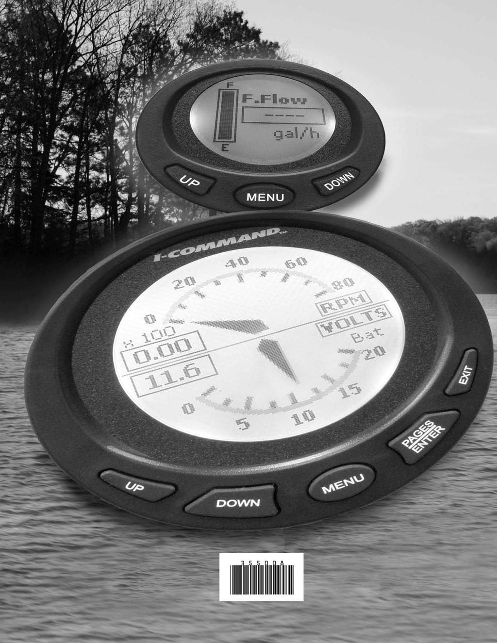
6 x 1 MENU I-COMMAND SYSTEM DESCRIPTION I-COMMAND SYSTEM DESCRIPTION The I-Command Digital Integrated Performance System uses plug and play networking technology based on NMEA 2 data communications standards (National Marine Electronics Association). These standards provide communications through a serial data network utilizing a Controller Area Network (CAN) integrated circuit (IC). This network operates at 25 kb/second and allows multiple electronic devices to be connected together on a common channel for easy information sharing. Multiple digital displays can be used to monitor and broadcast equipment and engine data RPM I-Command digital displays are designed specifically for NMEA 2 certified Evinrude E-TEC outboards. These displays provide enhanced engine and boat performance information. Multiple functions are integrated into the easy-to-use displays. Additional displays and accessories can be added with the plug and play design. 2 1 x 1 3 RPM 355 MENU psi 15.2 Water BAT:V 13.2 Volts MENU % FUL:L ALT:V 55 Volts 1 5 Water MPH 15.2 MENU U D Engine Trim 15 % MENU 5
7 I-COMMAND SYSTEM I-COMMAND DIGITAL SERIES FEATURES I-COMMAND DIGITAL SERIES FEATURES I-Command Digital Series Multifunction 3 ½ in. and 2 in. Displays 3 ½ in. Display 2 in. Display psi 15.2 Water BAT:V 13.2 Volts MENU % FUL:L ALT:V 55 Volts U D Engine Trim 15 % MENU 6 Functions & Screen Displays System Setup Adjustable Display Contrast and Audio Engine Warning Displays Single, Dual or Quad Page Display Single or Dual Page Display Displays in English or Metric Units Multi Engine RPM on Single Page Display (two or three engines) Tachometer Speedometer (1)or(2) GPS Position Longitude and Latitude (1) GPS Time (1) Engine Hour Meter Engine Trim Position (3) Engine Temperature Water Pressure (4) Alternator voltage (Evinrude E-TEC - 55 volt system) Battery voltage Engine Load percent of throttle Temperature (5) Sensor (water / air / fluid limit three) Barometric Pressure Fuel Tank Level (6)or(9)or(1) (three tank/engine limit) Oil Tank Level (7) (three tank limit) Depth (8) Fuel Flow Rate (9) (three engine limit) Fuel Consumption (9)and(1) Fuel Economy and Range (1)and(1) (three engine limit) Fuel Remaining and Fuel Used (6)and, or(1) Low Fuel Warning programmable Trip Fuel and Seasonal Fuel (1) (1) Requires NMEA 2 GPS receiver/antenna connected to network. Provides speed over ground (SOG). (2) Requires water speed input device - provides speed over water (SOW). (3) Available on V4/V6 Evinrude E-TEC outboards. (Not available on 25 HP through 9 HP Evinrude E-TEC.) (4) Requires accessory water pressure transducer kit. (5) Requires NMEA 2 depth transducer/triducer with temperature output or temperature sensor kit(s). (6) Requires accessory fuel tank level converter for each tank. See Select Fuel Remaining Source on page 33. (7) Requires accessory oil tank sending unit kit for each oil tank. (8) Requires NMEA 2 depth transducer. (9) Requires EMM interface. (1) Requires memory module. See Select Fuel Remaining Source on page 33.
 (1) Includes T-connector, PN 764151 (2) Includes adaptor, PN")
 764177 (1) 764176 (1)(2) 764178 (1)(2) Accessory Bezels 3 ½ in. 2 in.")

8 I-COMMAND SYSTEM I-COMMAND DIGITAL DISPLAYS I-Command Digital Displays Digital Display (black bezel) (1) Includes T-connector, PN (2) Includes adaptor, PN ½ in. 2 in (1) (1) (1)(2) (1)(2) Accessory Bezels 3 ½ in. 2 in. Gold White Chrome Black Trim Rings 3 ½ in. 2 in. Blue Red Black White Gold Chrome Platinum
9 I-COMMAND SYSTEM NETWORK SPECIFICATIONS NETWORK SPECIFICATIONS NMEA 2 Device NMEA 2 Network Diagram NMEA NMEA 2 2 Device Device Device cables Device cable Terminator NMEA 2 Device Buss cable (Network Buss) 6M (19 ft.) maximum Power supply & Ground connection Terminator 1M (328 ft.) Maximum Network Buss Length Cable Requirements NMEA 2 specifies wire requirements as follows: NMEA 2 Cable (Light / Micro Buss) Maximum Current 4 AMPS Resistance - Power Wire(s) 5.4 Ω per 1 M Power Wire Size 22 AWG Data Wire Size 24 AWG NMEA 2 specifies wire colors as follows: NMEA 2 Wire Designation Power supply (+VDC) Ground ( VDC) Shield (Drain) Data HI (Signal) Data LOW (Signal) Grounding Color Red Black Bare White Blue The network should be grounded at a SINGLE location. This is normally done at the power supply connection to the network and should be robustly connected to the boat s grounding system. There must be no other ground connections on the network to avoid ground loops, which can cause problems with network performance. Maximum Number of Devices A maximum of 5 devices can be attached to a NMEA 2 network. Load Equivalency The Engine Management Module (EMM) on Evinrude E-TEC outboards has a load equivalency number of 1. Less than 5 ma of the network s (CAN) power is used by the EMM. Linear Architecture NMEA 2 networks use a linear architecture. Linear describes the network buss as connected in a line. This design is easy to assemble and expand. The linear architecture must be maintained whenever an additional device is added to the network or the network is modified. This type of network also requires one terminator at each end of the network buss. Connect buss cables, terminators, and T-connectors to the buss connectors (side connectors) of the T-connectors. Connect devices to the device connector (center point) of the T-connector. 8
10 G P S R E C E I V E R MENU I-COMMAND SYSTEM NETWORK SPECIFICATIONS Network Buss Length Diagram x 1 RPM Network Buss Length The distance between any two points on the network must not exceed 1 meters (328 ft.). Measure the distance from the T-connector to the last device at each end of the network. Device cable lengths at the ends of the network must be included in the total network buss length calculation. Device Cable Lengths Network device cable lengths: Must not exceed 6 meters (19 ft.) for single device cable lengths Must not exceed 78 meters (256 ft.) for total device cable lengths Open Network Device Connectors Remove T-connectors to eliminate open network device connectors. There should be no open or unused network device connectors. 9
11 I-COMMAND SYSTEM QUICK CONNECT STYLE CONNECTORS QUICK CONNECT STYLE CONNECTORS Connector Identification Connectors have two configurations Male (pins) and Female (sockets) connected to the device connector of the T-connector Male (Pins) DeviceNet style 1. Shield (Drain) - Bare wire 2. Power (+VDC) - Red wire 3. Ground ( VDC) - Black wire 4. Data HI (Signal) - White wire 5. Data LOW (Signal) - Blue wire Terminating Resistors Female (Sockets) Terminating resistors are required for accurate network transmissions. Networks must be assembled with terminators positioned at both ends of the network buss. Each terminator uses a 12 Ω, 1/4 watt resistor to terminate data transmissions on the network. One terminator must be installed at each end of the I-Command network. DeviceNet style 1. Male buss connector 2. Female buss connector 3. Female device connector T-connectors can be installed at the end of a network. Connect a network buss cable to one side and a terminator into the other 2 1. Buss cable 2. Terminator 1 Multiple T-connectors can be installed in the middle or the end of a network. Use network buss cables to connect T-connectors Female (Sockets) Male (Pins) DeviceNet style) terminators T-Connectors and Buss Cables T-connectors provide device access to the network. T-connectors have two buss connectors and one device connector. Network devices must be 1. Buss cable 2. T-connectors IMPORTANT: An engine interface cable is required to connect an Evinrude E-TEC outboard to the network. 1
12 I-COMMAND SYSTEM QUICK CONNECT STYLE CONNECTORS SINGLE OUTBOARD A TWIN OUTBOARD A 1. Power harness, single engine 2. Terminator (Male) 3. Terminator (Female) 4. T-Connector 5. Buss cable 6. Engine Interface Cable (network to E-TEC outboard) 7. Power harness, multi-engine 11
13 I-COMMAND SYSTEM QUICK CONNECT COMPONENTS QUICK CONNECT COMPONENTS A 3A No. Description Part Number DeviceNet Style Connector 1 Terminator Kit (contains 1 male and 1 female) T-Connector Network Buss Cable - 1 ft Network Buss Cable - 6 ft Network Buss Cable - 15 ft Network Buss Cable - 25 ft Engine Interface Cable Kit (15 ft.) (1) Power Supply Kit - Single Engine (1) Power Supply Kit - Multiple Engines (1) Fuse ATO/ATC 3 Amp: (1) Includes T-Connector, P/N
14 IGNITION AND TRIM/TILT HARNESSES I-COMMAND SYSTEM IGNITION AND TRIM/TILT HARNESSES IMPORTANT: Do not use a MWS harness (or any other harness) in place of an I-Command Ignition and Trim/Tilt Harness or an I-Command Ignition and Trim/Tilt Adaptor Harness. These I-Command harnesses are built with 47 ohm resistors for the trim sender circuit and provide a switched B+ circuit for EMM operation. includes the 47 ohm resistor for the trim sender circuit. TO OUTBOARD Ignition and Trim/Tilt Harness Outboards rigged with I-Command use a unique Ignition and Trim/Tilt Harness. This harness provides a switched B+ connection for the EMM Harness and a 47 ohm resistor for the trim sender circuit. The Ignition and Trim/Tilt Harness is offered in various lengths and engine configurations. Single, twin and triple engine configurations are available. All twin and triple harnesses require the use of one Ignition and Trim/Tilt Adaptor Harness for each outboard. See Ignition and Trim/Tilt Adaptor Harness Used for Two and Three Engine Installations on p. 13 TO OUTBOARD PURPLE WIRE SWITCHED B+ Ignition and Trim/Tilt Adaptor Harness Used for Two and Three Engine Installations The Ignition and Trim/Tilt Adaptor Harness is used for twin and triple engine installations and connects to the outboard and a twin or triple Ignition and Trim/Tilt Harness. This required harness 13
15 I-COMMAND SYSTEM IGNITION AND TRIM/TILT HARNESSES No. Description Part Number Harness Lengths 12 ft. 15 ft. 2 ft. 25 ft. 28 ft. 1 Singe Outboard Ignition and Trim/Tilt Harness Twin Outboard Ignition and Trim/Tilt Harness Triple Outboard Ignition and Trim/Tilt Harness (1) Ignition and Trim/Tilt Adaptor Harness (2) 6 ft or 1 ft (1) Not shown (2) Must be used with Twin Outboard Ignition and Trim/Tilt Harness and Triple Outboard Ignition and Trim/Tilt Harness to connect to outboards. Use one Ignition and Trim/Tilt Adaptor Harnesses for each outboard (contains 47 ohm 1/4 watt resistor for trim sender circuit). 14
16 I-COMMAND SYSTEM IGNITION AND TRIM/TILT WIRING DIAGRAMS IGNITION AND TRIM/TILT WIRING DIAGRAMS SINGLE ENGINE OUTBOARD TRIM TILT CONNECTOR IGNITION/TRIM/TILT HARNESS OUTBOARD IGNITION CONNECTOR Not used on I-Command Digital Systems PURPLE WIRE (SWITCHED B+) BLACK WIRE (GROUND) KEY SWITCH IGNITION /TRIM/TILT ADAPTOR HARNESS (USE ONE FOR EACH OUTBOARD) TWIN ENGINE PURPLE WIRE (SWITCHED B+) IGNITION/TRIM/TILT HARNESS IGN IGN PURPLE WIRE (SWITCHED B+) Not used on I-Command Digital Systems BLACK WIRE (GROUND) KEY SWITCH NOTE: Multiple engine ignition/trim/tilt harnesses are avaialble in various lengths. 15
17 I-COMMAND SYSTEM ACCESSORIES ACCESSORIES Various NMEA 2 accessories are available to interface to the I-Command Digital System. This is achieved by adding an additional tee connector to the network buss. Description of Kit P/N Triducer, transom mount, Speed/Depth/Temp (1) Triducer, thru-hull, Plastic, Speed/Depth/Temp (1) Transducer, transom mount, Depth/Temp (No speed) (1) GPS Receiver/antenna (1) SOW Paddle Wheel Kit (1) Water Speed /Pressure Sensor Kit (1) Memory Module Kit (Fuel Manager) (1) Fluid Level Converter (unconfigured) (1)(2)(3) Fuel Level Converter Kit one fuel tank (instance ) (1)(4) Fuel Level Converter Kit two fuel tanks (instance and 1) (1)(4) Fuel Level Converter Kit three fuel tanks (instance, 1 and 2) (1)(4) Fuel Flow / Level Transducer Kit (1)(2)(4) Oil Tank Level Kit, 1.8 Gallon one engine one oil tank (instance ) (1)(4) Oil Tank Level Kit, 1.8 Gallon two engines two oil tanks (instance and 1) (1)(4) Oil Tank Level Kit, 3. Gallon one engine one oil tank (instance ) (1)(4) Oil Tank Level Kit, 3. Gallon two engines two oil tanks (instance and 1) (1)(4) Oil Tank Level Kit, 3. Gallon three engines three oil tanks (instance, 1 and 2) (1)(4) Oil Tank Level Converter Kit, 1 Gallon one oil tank (instance ) Engine Water Pressure Sensor (See Engine Water Pressure Sensor Kit on page 2) 583 (3) NMEA 2 Pressure Sensor Kit (See NMEA 2 Pressure Sensor Kits on page 2) (1)(2)(4) Temperature Sensor (water / air / fluid unconfigured) (1)(2) 3.5 inch I-Command Gauge Horn and Hardware Kit inch I-Command Gauge Horn and Hardware Kit (1) Includes T-connector(s), P/N (2) Configure using I-Command Digital display (3) Configure using Evinrude Diagnostics software (4) Connect to specific engine or accessory for correct network data to be displayed (Instance, 1, or 2) 16
18 I-COMMAND SYSTEM ACCESSORIES Instance Numbers I-Command networks (NMEA 2) allow multiple electronic devices to be connected together on a common network and can be configured to support many instances of duplicate or similar devices on the same network. Device identities and instance numbers are used to identify devices on a network. Additional devices (accessories) are added through careful network configuration. Refer to NETWORK SET on page 32 or I-Command User s Guides for engine and boat setup, fuel tank setup, oil tank setup, pressure sensor setup, and temperature sensor setup. Engines are identified from PORT to STAR- BOARD on the transom. See instance numbers in chart. Number of Outboards Port Instance Number Starboard or Center Starboard Fuel and oil tanks must be connected to the correct converter to provide accurate I-Command network information. Label converters and wiring by instance number (engine location or device location). Identify water pressure sensors and temperature sensors; and accurately label converters and wiring by instance number (engine location or device location). Device Description (1) Instance Number Engine Location or Device Location Is Device Configured on Network Engine 1 Port YES Engine 2 1 Starboard or Center YES Engine 3 2 Starboard YES Fuel Tank 1 Main fuel tank or tank 1 YES Fuel Tank 2 1 Auxiliary fuel tank or tank 2 Fuel Tank 3 2 Auxiliary fuel tank 2 or tank 3 Oil Tank 1 Label oil tank 1 YES Oil Tank 2 1 Label oil tank 2 Oil Tank 3 2 Label oil tank 3 Engine Water Pressure Sensor Use Evinrude Diagnostics Port, Center, Starboard NO NMEA 2 Pressure Sensor 1 Port YES NMEA 2 Pressure Sensor 2 1 Starboard or Center YES NMEA 2 Pressure Sensor 3 2 Starboard YES Temperature Sensor 1 Port or device location YES Temperature Sensor 2 1 Starboard / Center or device location Temperature Sensor 3 2 Starboard or device location (1) This chart provides device descriptions and instance numbers on a typical I-Command network and represents a boat assembled with three (3) engines. 17
19 I-COMMAND SYSTEM ACCESSORIES Fuel Tank Level Converter Kits Fuel tank level converter kits contain the fuel tank level converter(s) needed for specific I-Command network installations. Use the chart below to select the required kit or converter. Fuel tank level converters (analog to digital converters) must be installed to coincide with fuel tank instance (position). Refer to user information and setup information to reconfigure the instance numbers of converters. See Instance Numbers on page 17. Number of Fuel Tanks Fuel Tank Level Converter Kit P/N (1)(2) Fuel Tank Converter Instance Converter P/N (1)(2) (1)(2) (1)(2) (1)(2) Fluid Level Converters Fluid level converters (analog to digital converters) must be configured to provide proper input to the I-Command network. Fluid level converters must be configured to support a specific sending unit. Select fluid level converter(s) for fuel level, oil level, and water level as needed. Fluid level converters must be configured to support I-Command Digital displays. Refer to user information and setup information to reconfigure the instance numbers of converters. See Instance Numbers on page 17. Fluid Level Converter P/N Unconfigured (1)(2) (1) Includes T-connector, P/N (2) Configure with I-Command Digital display EP-15 Fuel Oil (1)(2) (1)(2) (1)(2) (1)(2) Length 12 ft. / 3.7 m (1) Includes T-connector(s), P/N (2) Connect the fuel tank level converter configured with the appropriate instance number to the specific fuel tank sending unit. Memory Module Kit A memory module kit provides fuel level and fuel management data for the I-Command network. Use with I-Command Digital displays ONLY. EP-15 Fuel Oil Memory Module Kit P/N (1) Length 12 ft. / 3.7 m (1) Includes T-connector, P/N EP- 85 Memory Module Length 2 ft. /.6 m 18
20 I-COMMAND SYSTEM ACCESSORIES Oil Tank Level Kits I-Command oil tank level kits include oil tank sending unit(s) and oil tank level converter(s). Oil tank level converters (analog to digital converters) provide oil tank information to the I-Command network and must be installed to coincide with oil tank instance (position). Refer to user information and setup information to reconfigure the instance numbers of converters. See Instance Numbers on page 17. Number of Oil Tanks Number of Sending Units and Converters Included in Kit Oil Tank Level Converter Instance Kit P/N 1.8 Gallon Oil Tank Level Kits (1)(2) 2 2 (1) Kit includes T-connector(s), P/N (2) Install the oil tank sending unit kit with the pre-configured oil tank level converter(s) in the appropriate oil tank. See Oil Tank Level Converters on page (1)(2) 3. Gallon Oil Tank Level Kits (1)(2) (1)(2) (1)(2) Oil Tank Level Converters A 1 gallon oil level converter kit is used in a single or a multiple engine installation which use one common oil tank. The oil level converter supplied with this kit is instance I. 1 Gallon Oil Tank Level Converter Kit Number of Converters Included in Kit Oil tank level converters must be installed to coincide with engine and oil tank instance (position). Refer to user information and setup information to reconfigure the instance numbers of converters. See Instance Numbers on page 17. Outboard Instance 1 2 Instance Converter P/N Engine Position Single engine Port engine on two or three engine installation Starboard engine on two engine installation Center engine on three engine installation Starboard engine on three engine installation Converter P/N Unconfigured (1) (1) Configure using the I-Command Digital display EP-15 Fuel Oil Length 12 ft. / 3.7 m 3 1. Sending Unit 2. Converter 3. T-connector 19
21 I-COMMAND SYSTEM ACCESSORIES Oil Tank Sending Units Oil tank sending units below are used to service I-Command digital oil tank sending unit kits. Sending Unit Height P/N 6.5 in. (1.8 gallon tank) (1) 8.5 in. (3. and 1 gallon tank) (1) (1) An oil tank level converter is required to connect to network NMEA 2 Pressure Sensor Kits NMEA 2 pressure sensor kits can be used to provide data for engine water pressure, fuel pressure, engine boost pressure, engine oil pressure, or transmission oil pressure. DO NOT mount this sensor under the engine cover. Refer to user information and setup information to reconfigure the instance numbers of converters. See Instance Numbers on page 17. Sensors (Converters) Included in Kit Sensor Converter Instance Kit P/N (1)(2)(3) (1)(2)(3) (1)(2)(3) Engine Water Pressure Sensor Kit An engine water pressure sensor kit provides water pressure input to the outboard s EMM. This input is processed by the EMM of the outboard then broadcast to the I-Command network. Used on 115 HP and larger Evinrude E-TEC outboards only. Configure this sensor using Evinrude Diagnostics software program. See NETWORK SET on page 32. (1) Kit includes T-connector, P/N (2) Install the pressure sensor kit with the pre-configured pressure sensor converter(s) in the appropriate location (3) Configure using the I-Command Digital display if needed Length 12 ft. / 3.7 m Engine Water Pressure Sensor Kit P/N 583 (1) (1) Configure using Evinrude Diagnostics software program 2

22 I-COMMAND SYSTEM ACCESSORIES GPS Receiver/Antenna These NMEA 2 GPS receivers provide location and speed over ground (SOG) input to the I-Command network. Network buss harnesses can be used to extend and make connections. Transducers and Triducers Transducers provide depth and temperature inputs to the I-Command network. Triducers provide depth, temperature and speed over water (SOW) inputs to the I-Command network. GPS Receiver/Antenna (NMEA 2) P/N Transducers (NMEA 2) P/N Transom Mount Transducer Transom Mount Triducer Thru-Hull Triducer G P S R E C 3 E I V E R Length 12 in. / 3cm Length 12 ft. / 3.7 m Transom Mount Transducer Length 12 ft. / 3.7 m Thru-Hull Triducer (plastic) IMPORTANT: Installations using I-Command Classic instruments require a Multifunction I-Command Classic Speedometer. 21
23 I-COMMAND SYSTEM ACCESSORIES Speed Transducer - Paddle Wheel A transom mount paddle wheel provides speed over water (SOW) input to the I-Command network. Speed Transducer (NMEA 2) P/N Length 12 ft. / 3.7 m Fuel Flow Transducer Kit Fuel flow transducer kits provide fuel flow data to the network. IMPORTANT: DO NOT use on 4-3 HP Evinrude E-TEC outboards. Fuel Flow Transducer Kit (1) Configure using I-Command Digital display P/N (1) Temperature Sensor Kit A temperature sensor kit provides air or fluid temperature. The sensor range is 4 to 176 F (-2 to 8 C). Length 12 ft. / 3.7 m Temperature Sensor Kit P/N (1) (1) Configure using I-Command Digital display EP- 35 TEMP Length 12 ft. / 3.7 m 22
24 I-COMMAND INSTALLATION INSTRUMENTS I-COMMAND INSTALLATION INSTRUMENTS Spacing of Instruments The minimum distances between instruments on a panel should be as follows: 3 13/16 (112 mm) center to center for 3 1/2 in. instruments 3 1/4 in. (95.5 mm) center to center for 3 1/2 in. instruments to 2 in. instruments 2 5/8 in. (77 mm) center to center for 2 in. instruments Panel Thickness Instruments can be mounted in panels up to 1 in. thick. Hole Sizes IMPORTANT: Check space behind panel to be sure adequate clearance for instruments exists before drilling panel. 3 1/2 in. Multifunction Gauge Cut 3 3/8 in. (99 mm) diameter hole in panel for 3 1/2 in. instruments. Secure instrument with nuts and bracket. 2 in. Gauge Cut 2 1/16 in. (52 mm) diameter hole in panel for 2 in. instruments. Secure instrument with spin nut. Fastening to Panel Insert instrument into panel hole. Thread spin nut onto threaded housing of instrument and tighten to back of panel. DO NOT exceed 1 in. lbs. (1.1 N m) If stud and bracket kits are used, tighten nuts finger tight. Warning Horn Connect the yellow wire from the instrument to the black wire of the warning horn. Connect the blue wire from the instrument to the red wire of the warning horn. 1. Warning horn Each instrument should be installed with a warning horn. Mount each warning horn in a protected area (out of the weather) and so horn is audible for operator. Navigation Lights Connecting the light wiring for the I-Command instrument to the boat s navigation lights will provide instrument lighting if the instrument backlight setting is set to lowest setting and the boat s navigation lights are turned ON. Connect the white wire from the instrument to the switched positive (B+) of the boat s navigation lights and the black wire from the instrument to ground (GND). 1 23
25 I-COMMAND INSTALLATION INSTRUMENTS Instrument Dimensions 3 1/2 in. Digital Series Multifunction Display.71 in. (18 mm) 1.95 in. (49.5 mm) 2.87 in. (72.9 mm) 2.2 in. (56 mm) 3.81 in. (96.9 mm) 3.34 in. (85 mm) 2 in. Digital Series Multifunction Display 2.36 in. (6 mm).54 in. (13.6 mm) 2. in. (51 mm) 2.8 in. (53 mm) 24
26 I-COMMAND INSTALLATION QUICK CONNECT NETWORK COMPONENTS QUICK CONNECT NETWORK COMPONENTS DeviceNet-Style T-Connector Dimensions Some T-connectors have different dimensions..813 in. (21 mm) 1.87 in. (47.5 mm) 3/16 in. (4.76 mm) Mounting DeviceNet-Style T-Connectors Mount T-connectors to flat mounting surfaces. Use washers or spacers behind the T-connector as needed. Check T-connector alignment. Incorrect mounting can damage the T-connectors resulting in broken wiring connections. T-connectors should be mounted with the Device connector facing down to prevent water intrusion. Tighten screws by hand to prevent damage. Groups of T-connectors can be stacked for mounting in larger network installations. CORRECT INCORRECT CORRECT CONNECTORS ARE DAMAGED Converter/Memory Module Dimensions.79 in. (2 mm) 3.44 in. (87 mm) 25
27 I-COMMAND INSTALLATION QUICK CONNECT NETWORK QUICK CONNECT NETWORK Lubricate all connector gaskets with Electrical Grease (dielectric) before assembly. T-Connectors or a terminator to the buss connectors of the T-connector. Refer to QUICK CONNECT NETWORK DIA- GRAMS on page 28. 1) Install ignition and trim/tilt wire harness. Ignition and trim/tilt harnesses are available in various lengths. Refer to IGNITION AND TRIM/TILT HARNESSES on page 13. Ignition and trim/tilt harnesses are available in various lengths for twin or triple engine installations. Use one ignition trim/tilt adaptor harness for each outboard connecting to a twin or triple configuration ignition and trim/tilt harness. 2) Organize the components required for the installation. Position components, identify harness routings, and determine locations for T-connectors. All network devices are installed by adding T-connectors. 3) Install power supply and T-connector. The I-Command network must be connected to a switched power source. Single Engine Power Supply Harness: Connect the red wire of the power supply harness to the purple switched B+ accessory wire of the ignition and trim/tilt wire harness. Connect the black wire of the power harness to the black ground wire of the ignition and trim/tilt harness. Multiple Engine Power Supply Harness: Connect the purple wire(s) of the power supply harness to the purple switched B+ accessory wires of the ignition and trim/tilt wire harness(s). Connect each black wire of the power harness to a black ground wire of the ignition and trim/tilt harness. (Optional: connect the red wire of the power harness to a switched B+ power supply of the boat.) Connect the network connector of the power supply harness to the device connector of the T-connector. Connect data cables, additional 4) Connect I-Command instrument(s). Add T-connectors to network as needed. Use one T-connector for each instrument. Connect the quick connect connector(s) from instrument(s) to the device connector of the T-connector. 5) Install the Engine Interface cable and T-connector. The outboard connects to the I-Command network as a device. Connect the 4-pin CANBus connector of the engine interface cable to the outboard. Route the 15 ft. (4.6 m) cable with the ignition and trim harness into the boat. Install the T-connector for the engine interface on the network. Connect the quick connect connector from engine interface cable to the device connector of the T-connector. For multiple outboards, install an additional T-connector and engine interface cable for each outboard. Remember to install a terminator to the open end of the T-connector if it is the last buss connector on the network Terminators 6) Connect buss cable(s). Use buss cables to extend the network s length and to connect T-connectors. Buss cables have a male connector on one end and a female connector on the other. Use the appropriate length buss cable to connect the T-connector group at the helm or console with 26
28 I-COMMAND INSTALLATION QUICK CONNECT NETWORK T-connectors positioned along the length of the hull. Connect the black wire (ground) of the converter to the sending unit s ground ( ) terminal. Use buss cables to extend the cable lengths between a device and a T-connector on the network. Limit total drop length to 19 ft. (6 m). Refer to NETWORK SPECIFICATIONS on page 8 7) Adding a network device. Other devices, such as another I-Command Digital gauge, an auxiliary fuel tank level sensor, or a GPS sensor can be added anywhere along the network buss Positive terminal 2. Ground terminal 1 Add a T-connector at the end of the network (between a T-connector and a terminator), between two T-connectors, or between a T-connector and a data cable. Add a new device by connecting device cable connector to the device (center) connector of T-connector. 8) Install fluid level converters. I-Command fluid level converters convert the standard analog electrical signal of sending units to the NMEA 2 signal. EP-15 Fuel Oil Remove excess cable length when connecting converters to sending units. IMPORTANT: If multiple unconfigured fluid level converters are installed, refer to NETWORK SET on page 32. Connect one fluid level converter to the network and configure converter. Once first converter is configured, connect second converter and configure. Continue connecting and configuring converters one at a time. Fuel Tank Level Converter Connect the red wire of the converter to the fuel tank sending unit s positive terminal (pink wire). Connect the fuel level converter connector to the device (center) connector of the T-connector. 9) Install terminators. Connect the appropriate terminator to the open buss connector of the T-connector at both ends of the network. 1) Set outboard identity For the outboard, run the latest version of Evinrude Diagnostics program and assign the outboard an identity for the network. Refer to Instance Numbers on page 17 and use Evinrude Diagnostics software to complete procedure. This procedure is required for multi-engine installations. 11) Check operation. Complete programming of the I-Command Network using an I-Command Multifunction Instrument. Refer to NETWORK TROUBLESHOOTING CHART on page 34 and the I-Command User s Guide for setup procedures. 12) Carefully route and secure all harnesses, converters, adaptors, and T-connectors. Once network is assembled and functional, position all harnesses and components carefully to prevent abrasion or contact with moving objects. T-connectors can be fastened with screws. Harnesses, converters, memory devices, and adaptors should be fastened using tie straps. 27
29 3A 3A MENU MENU MENU MENU MENU MENU I-COMMAND INSTALLATION QUICK CONNECT NETWORK DIAGRAMS QUICK CONNECT NETWORK DIAGRAMS TERMINATOR SINGLE OUTBOARD T-CONNECTORS NETWORK CABLE NETWORK CABLE TERMINATOR CONNECTIONS POWER SPLY HARNESS CONNECTIONS 3A ENGINE INTERFACE CABLE x 1 7 RPM 355 TWIN OUTBOARDS TERMINATOR T-CONNECTORS TERMINATOR NETWORK CABLE NETWORK CABLE CONNECTIONS CONNECTIONS ENGINE INTERFACE CABLES POWER SPLY HARNESS x 1 7 RPM x 1 7 RPM 355 TERMINATOR TRIPLE OUTBOARDS T-CONNECTORS TERMINATOR NETWORK CABLE NETWORK CABLE CONNECTIONS CONNECTIONS ENGINE INTERFACE CABLES POWER SPLY HARNESS x 1 7 RPM x 1 7 RPM x 1 7 RPM
30 MENU MENU I-COMMAND INSTALLATION QUICK CONNECT NETWORK DIAGRAMS G P S R E C 3 E I V E R x 1 7 RPM x 1 7 RPM 355 3A EP- 85 Memory Module I-COMMAND NETWORK DIAGRAM SINGLE OUTBOARDS 29
31 MENU MENU MENU I-COMMAND INSTALLATION QUICK CONNECT NETWORK DIAGRAMS G P S R E C 3 E I V E R x 1 7 RPM x 1 7 RPM x 1 7 RPM 355 IGN IGN 3A EP- 85 Memory Module I-COMMAND NETWORK DIAGRAM TWIN OUTBOARDS 3
32 MENU MENU MENU MENU I-COMMAND INSTALLATION QUICK CONNECT NETWORK DIAGRAMS x 1 7 RPM x 1 7 RPM x 1 7 RPM 355 G P S R E C 3 E I V E R x 1 7 RPM 355 IGN IGN IGN 3A EP- 85 Memory Module I-COMMAND NETWORK DIAGRAM TRIPLE OUTBOARDS 31

33 I-COMMAND INSTALLATION NETWORK SET NETWORK SET IMPORTANT: Set ENGINE OPTIONS on Evinrude E-TEC outboards before power is applied to the I-Command Network. Engine Options Use Evinrude Diagnostics software to set ENGINE OPTIONS. Settings include: Calibrate trim sensor Set multi engine identity (engine instance) See Instance Numbers on page 17 Engine water pressure sensor (if equipped) BOAT SET can be re configured after initial setup. Enter MENU and select SYSTEM SET. Press. Select ENG/TANK CFG (engine and tank configuration) and press. Engine Data Use ENG DATA (engine data) to assign a gauge to an engine. ENG DATA is only used in multiple engine installations. Enter MENU. Use / buttons to select SYSTEM SET. Press. Use / buttons to select ENG DATA. Press. Using / buttons select engine to be monitored. Press. Repeat for each I-Command gauge. Bus Devices Use BUS S (network buss devices) to view network devices. System Setup Refer to User s Guide provided with I-Command Digital gauge. Turn key switch to ON position. Display(s) should turn ON. (The default for new gauges is to display BOAT SET.) Boat Setup Use BOAT SET to select the appropriate number of engines and fuel tanks, and to enter fuel tank capacities. Press. Use / buttons to select the correct engine and tank configuration. Press. Use / buttons to enter the correct fuel tank capacity for each tank. Press to return to menu. IMPORTANT: Unconfigured devices such as temperature sensors and fluid level converters must be connected to network one at a time for proper identification and setup. Enter MENU. Use / buttons to select SYSTEM SET. Press. Use / buttons to select BUS S. Press. Using / buttons to select unconfigured device. Press. Continue ON-SCREEN PROCESS to configure. Fuel Tank Calibration Enter MENU. Use / buttons to select SYSTEM SET. Press. Use / buttons to select BUS S. Press. Use / buttons to select the fuel tank to be calibrated. Press. 32
34 I-COMMAND INSTALLATION NETWORK SET Select CALIBRATE. Press. Select TWO, THREE, or FIVE POINT CALIBRA- TION. Press. Continue ON-SCREEN PROCESS to calibrate. Select Fuel Remaining Source IMPORTANT: Perform the following procedure ON EACH GAUGE. Default setting is FLUID LEV SNSR. Enter MENU. Use / buttons to select SYSTEM SET. Press. Use / buttons to select FUEL SET. Press. Use / buttons to select FUEL REM SRC (Fuel Remaining Source). Press. Select ENG/FFLOW or FLUID LEV SNSR ENG/FFLOW (Engine Fuel Flow) - Requires installation of memory module kit. Uses Outboard s EMM software to calculate fuel consumption. Total fuel use is calculated based on EMM fuel tables and subtracted from fuel tank capacity entered during setup. IMPORTANT: Fuel flow data from EMM is required. User must enter amount of fuel added at each fill up or perform the refill tank procedure in FUEL MANAGER. A GPS antenna must be installed for Fuel Economy and Fuel Range features to be functional. FLUID LEV SNSR (Fluid Level Sensor) - Requires installation of a fuel tank level converter. Use s fuel tank sending unit to calculate remaining fuel and fuel used. Remaining fuel is calculated based on sending unit accuracy, capacity entered during setup, and fuel consumed from tank. Use the FIVE POINT CALIBRATION in TANK CALIBRA- TION to achieve best performance of this option. IMPORTANT: A GPS antenna and memory module kit must be installed to track seasonal fuel, trip fuel, fuel range, and fuel economy. Change Units Enter MENU. Use / buttons to select SYSTEM SET. Press. Use / buttons to select CHANGE UNITS. Press. Using / buttons to select option. Display Category Speed/Dist Temperature Pressure Depth GPS Coordinates Volume Speed Range Required for gauges set to analog display. Enter MENU. Use / buttons to select SYSTEM SET. Press. Use / buttons to select SPEED RANGE. Press. Using / buttons to select option. Pages - Add Unit of Measure Options Statute - Nautical - SI (metric) Farenheit - Celsius Imperial/US - SI (metric) Feet - Fathoms - Meters Deg/Min Deg/Min/Sec US Gallons - Liters IMPORTANT: Perform the following procedure on each gauge. Add analog or digital display pages to display additional data from added devices such as fluid level sensors, water pressure transducers, water pressure sensors and temperature sensors. Enter MENU. Use / buttons to select. Press. Use / buttons to select ADD PAGE. Press. Single - Analog or Digital Dual - Analog or Digital Quad - Analog or Digital Diagnostics Engine Trim Page Display Options Trim Tabs GPS Position Rudder Clock Fuel Manager 33
35 I-COMMAND INSTALLATION NETWORK TROUBLESHOOTING CHART NETWORK TROUBLESHOOTING CHART SYMPTOM POSSIBLE CAUSE / PROCEDURE (1) I-Command System does not work I-Command instrument display is erratic I-Command instrument turns on but ---- is displayed on LCD I-Command instrument displays are inconsistant. Some pages display data correctly and some pages only display dash marks On a multi-engine installation, I-Command instruments display data for one engine. Is red wire of power supply harness connected to switched B+ (purple wire) on dash board side of Ignition / trim and tilt harness. Is black wire of power supply harness connected to ground? Is the power supply harness connected to device connector of the T-connector? Blown 3 A fuse in Power Supply Harness? Check all wiring, connectors, T-connectors, network buss cables, and device connections. Disconnect device connectors from network. Isolate shorted T-connectors, cables, accessories or displays. Are two terminators installed in the network, one at each end? Check all wiring, connectors, T-connectors, network buss cables, and device connections. Check NMEA Line Voltage listed in the NMEA Information Menu. Is the EMM cable connected to the engine s EMM? Is the EMM cable connected to the device connector (center connector) of the T-connector? Check T-connector. Is housing cracked or pins bent? Is EMM programmed for engine position (instance). Set to, 1 or 2 using Evinrude Diagnostic software. This is required for multi-engine installations. Is I-Command display configured to match engine position (instance)? Pages displaying dash marks ---- are not receiving data from the device assigned to the page. Check related connections. Verify the device is listed on the BUS S list and configured properly. Is EMM programmed for engine position (instance). Set to, 1 or 2 using Evinrude Diagnostic software. This is required for multi-engine installations. Is I-Command display configured to match engine position (instance)? Check the EMM cables and the EMM cable connections for each engine. 34
36 I-COMMAND INSTALLATION NETWORK TROUBLESHOOTING CHART Fuel level will not display Fuel Manager Data will not display Oil tank level does not display SYMPTOM POSSIBLE CAUSE / PROCEDURE (1) Requires FLUID LEVEL CONVERTER (FUEL) and I-Command display configured with FUEL REM SRC set to FLUID LEV SNSR or memory module kit and I-Command display configured with FUEL REM SRC set to ENG/FFLOW. Is fuel tank sending unit correct - resistance range from 33 ohms to 24 ohms? Is the float arm of the sending unit moving without obstruction? Is the FLUID LEVEL CONVERTER connected to the fuel tank sending unit? Connect the red wire of FLUID LEVEL CONVERTER to the center terminal (positive terminal) of the fuel tank sending unit and black wire to ground terminal (black). Is the network connector of the FLUID LEVEL CON- VERTER connected to device connector of the T-connector? Is the T-connector damaged? Is T-connector housing cracked or electrical pins bent? Is FUEL LEVEL on the BUS S list of the I-Command display? Is a page for FUEL LEVEL or FUEL MANAGER added and configured? Is FLUID LEVEL calibrated for fuel tank(s)? Requires MEMORY MODULE and setup of the I-Command display. Is MEMORY MODULE on the BUS S list of the I-Command display? Is a page for FUEL MANAGER added and configured? Is I-Command display configured with FUEL REM SRC set to ENG/FFLOW? See Setup. Is the T-connector damaged? Is T-connector housing cracked or electrical pins bent? Requires FLUID LEVEL CONVERTER (OIL) with the proper instance program. Is the network connector of the FLUID LEVEL CON- VERTER connected to device connector of the T-connector? Is the T-connector damaged? Is T-connector housing cracked or electrical pins bent? Is OIL TANK on the BUS S list of the I-Command display? Is a page for OIL LEVEL added and configured? Is I-Command display configured with correct oil tank instance (position)? 35
37 I-COMMAND INSTALLATION NETWORK TROUBLESHOOTING CHART SYMPTOM POSSIBLE CAUSE / PROCEDURE (1) Requires input from a NMEA 2 GPS receiver. Is NMEA 2 GPS receiver connected to device connector of a T-connector of the network? Speed-Over-Ground (SOG) does not display Is the T-connector damaged? Is T-connector housing cracked or electrical pins bent? Is GPS MODULE on the BUS S list of the I-Command display? Is a page for Speed-Over-Ground (SOG) added? Requires input from a NMEA 2 speed transducer. Is NMEA 2 speed transducer connected to device connector of a T-connector of the network? Speed-Over-Water (SOW) does not display Is the T-connector damaged? Is T-connector housing cracked or electrical pins bent? Is SPEED OVER WATER on the BUS S list of the I-Command display? Is a page for Speed-Over-Water (SOW) added? Requires input from NMEA 2 depth transducer. Is NMEA 2 depth transducer connected to device connector of a T-connector of the network? Water depth does not display Is the T-connector damaged? Is T-connector housing cracked or electrical pins bent? Is WATER DEPTH TRANSDUCER on the BUS S list of the I-Command display Is a page for Water depth added? Requires input from NMEA 2 temperature transducer. Is I-Command display configured with correct temperature sensor information? Temperature does not display Is the T-connector damaged? Is T-connector housing cracked or electrical pins bent? Is TEMPERATURE TRANSDUCER on the BUS S list of the I-Command display Is a page for Temperature transducer added? Is the proper I-Command Ignition and Trim harness installed? For multiple engine installation, are Ignition and Trim Engine Trim information is not accurate or ADAPTOR HARNESSES installed? does not display Use the EVINRUDE DIAGNOSTICS software to set and trim limits (115 HP and higher) Is a page for Engine Trim added? Is a page for WATER PRESSURE added to the I-Command display and is the display configured for correct WATER PRESSURE information? Water Pressure does not display Is the T-Connector damaged? Is the T-Connector housing cracked or electric pins bent? (NMEA 2 (NMEA 2 pressure sensor) sensor) Is the WATER PRESSURE sensor on the bus devices list of the I-Command display? (NMEA 2 sensor). 36
38 I-COMMAND INSTALLATION NETWORK TROUBLESHOOTING CHART SYMPTOM POSSIBLE CAUSE / PROCEDURE (1) Water Pressure does not display (Evinrude E-TEC water pressure sensor) Is the WATER PRESSURE sensor setup using the Evinrude Diagnostics software? Is a page for WATER PRESSURE added to the I-Command display? Note: WATER PRESSURE is not listed on the Buss Devices list. (1) I-Command device must be connected to device connector (center) of T-connector. Check condition of all T-connector(s). Inspect pins and sockets of T-connectors and device connectors carefully. Damaged or shorted connectors can damage 5 amp fuse. 37
39 I-COMMAND INSTALLATION NETWORK TROUBLESHOOTING CHART 38
40
Installation Guide *353109*
 Installation Guide *353109* SAFETY INFORMATION This instruction booklet is written for qualified, factory-trained technicians who are already familiar with the use of Evinrude /Johnson Special Tools. This
POWERHEAD REPLACEMENT KIT INSTALLATION INSTRUCTIONS
 APPLICATION POWERHEAD REPLACEMENT KIT INSTALLATION INSTRUCTIONS Use this instruction sheet when installing powerhead replacement kits on Evinrude E-TEC 60 V outboards, 5 00 Hp. DO NOT install on any other
TILT ASSIST KIT, P/N INSTALLATION INSTRUCTIONS
 TILT ASSIST KIT, P/N 50069 INSTALLATION INSTRUCTIONS APPLICATION This kit is designed for use on the following -cylinder outboards with manual tilt: 00 and newer Evinrude E-TEC 0 HP recreational and 60
ELECTRIC START KIT, P/N INSTALLATION INSTRUCTIONS
 ELECTRIC START KIT, P/N 5005580 INSTALLATION INSTRUCTIONS APPLICATION This kit is designed for use on 004 and newer Evinrude E-TEC rope start outboards. DO NOT install on any other models. SAFETY INFORMATION
FUEL INJECTOR / VAPOR SEPARATOR SEAL KIT, P/N INSTALLATION INSTRUCTIONS
 FUEL INJECTOR / VAPOR SEPARATOR SEAL KIT, P/N 500793 INSTALLATION INSTRUCTIONS APPLICATION This kit is designed for use on 009 and newer Evinrude E-TEC 5 30 HP outboards. DO NOT install on any other models.
BATTERY CHARGING KIT, P/N INSTALLATION INSTRUCTIONS
 BATTERY CHARGING KIT, P/N 50658 INSTALLATION INSTRUCTIONS APPLICATION This kit is designed for use on 00 and newer Johnson and 5 HP, -stroke outboards. DO NOT install on any other models. SAFETY INFORMATION
REMOTE CONTROL CONVERSION KIT, P/N INSTALLATION INSTRUCTIONS
 REMOTE CONTROL CONVERSION KIT, P/N 5036662 INSTALLATION INSTRUCTIONS APPLICATION This kit is designed for use on 2005 (SO) and newer Johnson 9.9 and 5 HP (302 cc) 4-Stroke outboards. DO NOT install on
BINNACLE MOUNT REMOTE CONTROL INSTALLATION AND USER S GUIDE
 BINNACLE MOUNT REMOTE CONTROL INSTALLATION AND USER S GUIDE APPLICATION Use for Evinrude E-TEC binnacle mount remote control assemblies designed for Evinrude and Johnson outboards. SAFETY INFORMATION For
INSTALLATION INSTRUCTIONS REMOTE OIL TANK KIT APPLICATION
 INSTALLATION INSTRUCTIONS REMOTE OIL TANK KIT APPLICATION This instruction sheet is a guide for proper installation of components supplied in this kit. These components are designed for use on Evinrude
INSTALLATION INSTRUCTIONS OUTBOARD JET PUMP SECONDARY SHIFT CABLE
 APPLICATION INSTALLATION INSTRUCTIONS OUTBOARD JET PUMP SECONDARY SHIFT CABLE This instruction sheet is intended to supplement the aftermarket jet pump manufacturer s installation instructions. Evinrude
REMOTE CONTROL CONVERSION KIT, P/N INSTALLATION INSTRUCTIONS
 REMOTE CONTROL CONVERSION KIT, P/N 5035779 INSTALLATION INSTRUCTIONS APPLICATION This kit is designed for use on 003 (ST) and newer Johnson 4, 5, 6 HP (38 cc) 4-Stroke outboards. DO NOT install on any
Bombardier Recreational Products Inc.
 Bombardier Recreational Products Inc. REMOTE CONTROL CONVERSION KIT, P/N 5035775 INSTALLATION INSTRUCTIONS APPLICATION This kit is designed for use on 000 (SS) and newer Evinrude or Johnson 5 and 30 HP
REPLACEMENT POWERHEAD SEAL KIT INSTALLATION INSTRUCTIONS
 APPLICATION REPLACEMENT POWERHEAD SEAL KIT INSTALLATION INSTRUCTIONS This kit is used for Evinrude E-TEC 3.3 liter 90 V6 models. Later model outboards do not require all components supplied. Older models
PREWIRED SURFACE MOUNT REMOTE CONTROL INSTALLATION INSTRUCTIONS
 PREWIRED SURFACE MOUNT REMOTE CONTROL INSTALLATION INSTRUCTIONS APPLICATION This surface mount remote control assembly is designed for use on Evinrude and Johnson outboards. SAFETY INFORMATION For safety
TILLER HANDLE KIT, P/N and INSTALLATION INSTRUCTION
 TILLER HANDLE KIT, P/N 5005579 and 5005777 INSTALLATION INSTRUCTION APPLICATION This kit is designed for use on 004 (SR) and newer Evinrude E-TEC 75 and 90 HP outboards. DO NOT install on any other models.
FUEL INJECTOR FASTENER REPLACEMENT KIT INSTALLATION INSTRUCTIONS
 FUEL INJECTOR FASTENER REPLACEMENT KIT INSTALLATION INSTRUCTIONS APPLICATION Use the information contained in this instruction sheet to replace fuel injector retainer fasteners on 00, certain 004 and 005
TILLER HANDLE KITS, P/N , , , , , INSTALLATION INSTRUCTIONS
 TILLER HANDLE KITS, P/N 50075, 50076, 5007075, 5007076, 5007557, 5007558 INSTALLATION INSTRUCTIONS APPLICATION Use this instruction sheet when installing the above tiller handle kits on Evinrude E-TEC
*357683* EXHAUST BACK PRESSURE KIT - P/N SAFETY INFORMATION DANGER WARNING CAUTION NOTICE. Outboard Engines
 Outboard Engines EXHAUST BACK PRESSURE KIT - P/N 357682 Use this kit on 2007 2009 Evinrude E-TEC 115 HP V4 (1.7 L) outboards with 2-piece exhaust. Do NOT install on any other outboards SAFETY INFORMATION
TILLER HANDLE KIT, P/N and INSTALLATION INSTRUCTIONS
 TILLER HANDLE KIT, P/N 5005579 and 5005777 INSTALLATION INSTRUCTIONS APPLICATION This kit is designed for use on 004 (SR) and newer Evinrude E-TEC 75 and 90 HP outboards. DO NOT install on any other models.
EVINRUDE ICON GAUGES.
 EVINRUDE ICON 2 FROM THE MAKERS OF THE ULTIMATE OUTBOARD EVINRUDE ICON GAUGES. THE ULTIMATE GAUGES ARE HERE. FROM THE NO-NONSENSE BASIC SERIES TO THE FUNCTION- FILLED PRO SERIES, EVINRUDE ICON OFFERS BOATERS
EVINRUDE ICON GAUGES.
 EVINRUDE ICON 2 FROM THE MAKERS OF THE ULTIMATE OUTBOARD EVINRUDE ICON GAUGES. The ultimate gauges are here. FROM The no-nonsense BASIC SERIES TO ThE FUNCTIONfilled Pro Series, Evinrude ICON offers boaters
IMPORTANCE OF PROPER SET-UP, INSTALLATION, AND PRE-DELIVERY SERVICE
 IMPORTANCE OF PROPER SET-UP, INSTALLATION, AND PRE-DELIVERY SERVICE For Your Customer s Safety Proper set-up, installation and pre-delivery service are essential to the customer s safety and the reliability
IS0306 rev. B ecn /2013. MG Tachometer (NMEA2000 and J-1939) TACH 1760 RPM FUEL. Installation / User Manual.
 TACH 1760 RPM FUEL. Installation / User Manual.") IS0306 rev. B ecn 9055 11/2013 MG3000 - Tachometer (NMEA2000 and J-1939) TACH 1760 RPM FUEL Installation / User Manual www.faria-instruments.com IMPORTANT: This User s Guide outlines the functionality
IS0306 rev. B ecn 9055 11/2013 MG3000 - Tachometer (NMEA2000 and J-1939) TACH 1760 RPM FUEL Installation / User Manual www.faria-instruments.com IMPORTANT: This User s Guide outlines the functionality
IMPORTANCE OF PROPER SET-UP, INSTALLATION, AND PRE-DELIVERY SERVICE
 IMPORTANCE OF PROPER SET-UP, INSTALLATION, AND PRE-DELIVERY SERVICE For Your Customer s Safety Proper set-up, installation and pre-delivery service are essential to the customer s safety and the reliability
6 Gauge Box Set with Programmable Speedometer. Made in the USA. Caution. Speedometer Parts. Tachometer Parts. Fuel Level Gauge Parts.
 6 Gauge Box Set with Programmable Speedometer Caution Disconnect the battery during installation. Tighten nuts on the backclamp only slightly more than you can tighten with your fingers. Six inch-pounds
Commander IS0128 ISO128E ECR# /04. Tachometer/ Engine Hourmeter
 Commander Tachometer/ Engine Hourmeter Analog Tachometer Digitally displays Hours Engine Has Been Run Fuel Level Other Features if Available: Fuel anagement Fuel Flow in GPH or LPH Total or Trip Fuel Used
Installation and User's Guide
 Installation and User's Guide SYSEM OVERVIEW SYSEM OVERVIEW ABLE OF CONENS ABLE OF CONENS DESCRIPION...................................................................... DISPLAY FEAURES................................................................
Owner s Manual. MG2000 Speedometer IS0211. for use with SmartCraft Tachometer
 Owner s Manual MG2000 Speedometer for use with SmartCraft Tachometer IS0211 rev. E ecr#6395 08/2006 4/5/05 Changes 12/21 Index Description Available Functions for display page 1 Default Screens page 1
Operation Manual. For technical help please contact Livorsi Marine at or us at
 For technical help please contact Livorsi Marine at 4-5- or email us at info@livorsi.com This Operation Manual system is compatible with any Smartcraft, NMEA, J99 or Indmar engine. Livorsi Marine Inc 5
NMEA 2000 ENGINE INFORMATION Suzuki, Yamaha, Evinrude
 Suzuki NMEA 2000 ENGINE INFORMATION Suzuki, Yamaha, Evinrude Suzuki has engine models compatible with NMEA 2000 that can be configured using our head units and gauges. An engine interface cable (EP-20)
STANDARD STEEL PLOW BLADE ASSEMBLY INSTRUCTIONS
 WESTERN PRODUCTS, P.O. BOX 245038, MILWAUKEE, WI 53224-9538 FORM NO. 13590 September 1, 1999 STANDARD STEEL PLOW BLADE Blade No. 60120 or 60125, or 60018 A, Q, & L Box No. 61720 Hydraulics Box No. 56365
BRP US Inc. / Outboard Engines Division After Sales Support P.O. Box 597 Sturtevant, WI 53177
 IMPORTANT: This User s Guide outlines the functionality and usage of the I-Command Integrated Performance System. Before using the I-Command Digital gauge, first read and understand ALL of the supplied
29048, 29049, 29050, 29051, 29052, 29053, 29054,
 April 15, 2014 Lit. No. 29225, Rev. 11 29048, 29049, 29050, 29051, 29052, 29053, 29054, 29400 5 HARNESS KIT 3 PORT ISOLATION MODULE LIGHT SYSTEM w/2 PLUG SYSTEM HARNESSES Installation Instructions Read
Western Products, PO Box , Milwaukee, WI MOUNT KIT
 Western Products, PO Box 245038, Milwaukee, WI 53224-9538 www.westernplows.com January 1, 2009 Lit. No. 67941, Rev. 02 67865 MOUNT KIT Chevy/GMC 1500/2500/3500 4X4 1988-98 Chevy/GMC 2500 & 3500 Classic
SPORT/UTILITY BLADE ASSEMBLY INSTRUCTIONS
 WESTERN PRODUCTS, P.O. BOX 245038, MILWAUKEE, WI 53224-9538 FORM NO. 13629 September 1, 1999 SPORT/UTILITY BLADE ASSEMBLY INSTRUCTIONS Sport/Utility Blade No. 61300 A, Q & L Box No. 61930 Hydraulics Box
Western Products, PO Box , Milwaukee, WI WIDE OUT Snowplow 52225, Installation Instructions CAUTION
 Western Products, PO Box 245038, Milwaukee, WI 53224 9538 www.westernplows.com June 1, 2016 Lit. No. 49589, Rev. 02 WIDE OUT Snowplow 52225, 52810 Installation Instructions Read this document before installing
INSTALLATION INSTRUCTIONS
 INSTALLATION INSTRUCTIONS For safety reasons, this kit must be installed by an authorized Evinrude/Johnson dealer. These installation instructions contain information that can help prevent personal injury
AUTO GLIDE INSTALLATION GUIDE MANUAL A
 GLIDE INSTALLATION GUIDE MANUAL A TABLE OF CONTENTS.0 PRODUCT OVERVIEW 3-4. System Requirements 4.0 GLIDE MECHANICAL INSTALLATION 5-6. Auto Glide Key Pad Installation. Replacing Existing 3 LED Indicator
THIS MANUAL DESCRIBES THE SMARTCRAFT GAUGE SYSTEMS AVAILABLE FOR YOUR BOAT
 Systems Monitor Operation Manual THIS MANUAL DESCRIBES THE SMARTCRAFT GAUGE SYSTEMS AVAILABLE FOR YOUR BOAT 2004, Mercury Marine 90-895202 204 0 TABLE OF CONTENTS Legend..............................................
Model: AEM14 Analog Engine Monitor
 Model: AEM14 Analog Engine Monitor Installation and Setup Manual Version 1 Table of Contents Monitor Overview DMK Engine Monitor Kit Section 1: Initial Setup 1.1 Internal Settings Switches Figure 1. AEM14
29048, 29049, 29050, 29051, 29052, 20953, 29054,
 July 15, 2008 Lit. No. 29225, Rev. 06 29048, 29049, 29050, 29051, 29052, 20953, 29054, 29400-2 HARNESS KIT 3-PORT ISOLATION MODULE LIGHT SYSTEM w/2-plug SYSTEM HARNESSES Installation Instructions Read
P.O. Box 529 Rockland, Maine MOUNT KIT. Installation Instructions
 Fisher Engineering P.O. Box 529 Rockland, Maine 04841 www.fisherplows.com July 15, 2007 Lit. No. 29567, Rev. 02 Toyota Tundra MOUNT KIT Installation Instructions 2007 - This mount is for use with the Minute
MOUNT KIT PERSONAL PLOW
 August 1, 2018 Lit. No. 28476, Rev. 01 1233 MOUNT KIT PERSONAL PLOW Ford F-150 4X4 2004-08 Installation Instructions Read this document before installing the snowplow. See your sales outlet/website for
LIMITED WARRANTY * & FREE RIGGING **
 JULY 1, 2016 SEPTEMBER 6, 2016 E-TEC SUMMER SALES EVENT 6-YEAR LIMITED WARRANTY * & FREE RIGGING ** 2016 BRP US Inc. (BRP). All rights reserved. Trademarks of Bombardier Recreational Products Inc. or its
SUZUKI MODULAR INSTRUMENT SYSTEM
 SUZUKI MODULAR INSTRUMENT SYSTEM (SMIS) uses an easy to connect and expandable cable system to transmit graphic and numerical data to Multi-Function gauges. Easy to set up and install system can be used
MF 9520 / 9540 / 9560, Challenger 540C / 560C
 Ag Leader Combine Installation Note: Indented items indicate parts included in an assembly listed above Part Name/Description Part Number 9520 Quantity by Model 9540 540C Parts Kit 2001312-69 1 1 1 Drill
Installation Instructions for Remote Mount HMI 211 Display Panel Kit A045J206
 Instruction Sheet 7-2013 Installation Instructions for Remote Mount HMI 211 Display Panel Kit A045J206 1 Introduction The information contained within is based on information available at the time of going
6 Gauge Box Set IS0332
 Caution 6 Gauge Box Set IS0 Rev. A ecr 878 /0 Disconnect the battery during installation. Tighten nuts on the back clamp only slightly more than you can tighten with your fingers. Six inch-pounds of torque
MOUNT KIT. Polaris Ranger Installation Instructions CAUTION. Read this document before installing the snowplow. CAUTION
 December 1, 2017 Lit. No. 76854, Rev. 00 MOUNT KIT Polaris Ranger 1000 2018 - Installation Instructions Read this document before installing the snowplow. See your sales outlet/website for specific vehicle
MOUNT KIT. Arctic Cat 700 HDX Exmark 500S, 700S Toro 500 EFI, 700 EFI Installation Instructions CAUTION
 January 15, 2019 Lit. No. 76660, Rev. 02 35148 MOUNT KIT Arctic Cat 700 HDX 2014 17 Exmark 500S, 700S 2015 17 Toro 500 EFI, 700 EFI 2015 17 Installation Instructions Read this document before installing
Models 8100PP & 86110LP. Installation Instructions CAUTION. Read this document before installing the snowplow. CAUTION
 September 15, 2010 Lit. No. 48645, Rev. 02 POWER PLOW Snowplows Models 8100PP & 86110LP Installation Instructions Read this document before installing the snowplow. See your BLIZZARD outlet/web site for
MOUNT KIT PERSONAL PLOW
 November 15, 2018 Lit. No. 40942, Rev. 01 33923 MOUNT KIT PERSONAL PLOW Dodge Ram 1500 2009-18 Dodge Ram 1500 Classic 2019 Dodge Ram 1500 Rebel 2016-18 Dodge Ram 1500 Rebel Classic 2019 Installation Instructions
REGULATED BATTERY CHARGING KITS P/N & INSTALLATION INSTRUCTIONS
 REGULATED BATTERY CHARGING KITS P/N 505 & 505 INSTALLATION INSTRUCTIONS Used for installation of Regulated Battery Charging Kits P/N s 505 and 505 on 00 and newer Stroke 9.9 & 5 HP, Manual & Electric Start
MOUNT KIT PERSONAL PLOW
 August 15, 2007 Lit. No. 64608, Rev. 01 3723 MOUNT KIT PERSONAL PLOW Jeep Wrangler 1997-2006 Installation Instructions Read this document before installing the snowplow. See your sales outlet/web site
50 Gordon Drive, Rockland, Maine MOUNT KIT. Jeep Wrangler Installation Instructions
 Fisher Engineering 50 Gordon Drive, Rockland, Maine 04841-2139 www.fisherplows.com April 1, 2008 Lit. No. 29215, Rev. 01 MOUNT KIT Jeep Wrangler 1997-06 Installation Instructions Read this document before
Blizzard, PO Box , Milwaukee, WI B Undercarriage Kit. John Deere Gator XUV/HPX
 Blizzard, PO Box 245038, Milwaukee, WI 53224 9538 www.blizzardplows.com April 15, 2014 Lit. No. 41403, Rev. 01 B35126 Undercarriage Kit John Deere Gator XUV/HPX 2009-11 Heavy duty suspension required.
MOUNT KIT. Installation Instructions CAUTION. Read this document before installing the snowplow. CAUTION
 November 1, 2017 Lit. No. 72342, Rev. 00 MOUNT KIT Nissan Titan 2016 - Installation Instructions Read this document before installing the snowplow. See your sales outlet/website for specific vehicle application
MOUNT KIT PERSONAL PLOW
 August 1, 2006 Lit. No. 29316, Rev. 01 MOUNT KIT PERSONAL PLOW Nissan Frontier/Pathfinder 2005 - Installation Instructions Read this document before installing the snowplow. See your sales outlet for specific
MOUNT KIT Ford F-150 4X
 Fisher Engineering 50 Gordon Drive, Rockland, Maine 04841-2139 www.fi sherplows.com June 15, 2009 Lit. No. 64463, Rev. 03 MOUNT KIT Ford F-150 4X4 2004-08 Installation Instructions Read this document before
8100PP & 86110LP POWER PLOW Snowplows
 April 1, 2010 Lit. No. 40690, Rev. 02 8100PP & 86110LP POWER PLOW Snowplows Installation Instructions Read this document before installing the snowplow. See your BLIZZARD outlet/web site for specific vehicle
EJ212 Electric Jack 1 Ton (2,000 lbs) Assembly & Operating Instructions
 Assembly & Operating Instructions") EJ212 Electric Jack 1 Ton (2,000 lbs) Assembly & Operating Instructions READ ALL INSTRUCTIONS AND WARNINGS BEFORE USING THIS PRODUCT. This manual provides important information on proper operation & maintenance.
EJ212 Electric Jack 1 Ton (2,000 lbs) Assembly & Operating Instructions READ ALL INSTRUCTIONS AND WARNINGS BEFORE USING THIS PRODUCT. This manual provides important information on proper operation & maintenance.
Western Products, PO Box , Milwaukee, WI , 75700, 75710, 76901, 76974, 76980, ,
 Western Products, PO Box 245038, Milwaukee, WI 53224 9538 www.westernplows.com December 15, 2016 Lit. No. 43184, Rev. 02 PRO PLUS Snowplow 74750, 75700, 75710, 76901, 76974, 76980, 75700 1, 75710 1 Installation
Explorer S310. Speed Instrument Installation and Operation Manual.
 Explorer S310 Speed Instrument Installation and Operation Manual www.northstarnav.com IMPORTANT SAFETY INFORMATION Please read carefully before installation and use. DANGER! WARNING! CAUTION CAUTION This
50 Gordon Drive, Rockland, Maine MOUNT KIT
 Fisher Engineering 50 Gordon Drive, Rockland, Maine 04841 2139 www.fisherplows.com 7189 November 15, 2018 Lit. No. 40963, Rev. 01 MOUNT KIT Dodge Ram 1500 2009-18 Dodge Ram 1500 Classic 2019 Dodge Ram
TrynEx International, LLC, 531 Ajax Drive, Madison Heights, MI , POWER PLOW Snowplow
 TrynEx International, LLC, 531 Ajax Drive, Madison Heights, MI 48071 2429 www.snowexproducts.com December 15, 2016 Lit. No. 52238, Rev. 03 8100, 8611 POWER PLOW Snowplow 77750, 77755, 77850, 77850-1 Installation
Blizzard, PO Box , Milwaukee, WI UNDERCARRIAGE KIT. Dodge Ram 2500/3500. Installation Instructions CAUTION
 Blizzard, PO Box 245038, Milwaukee, WI 53224-9538 www.blizzardplows.com November 15, 2009 Lit. No. 41415, Rev. 00 33885 UNDERCARRIAGE KIT Dodge Ram 2500/3500 2010 - Installation Instructions Read this
Log Splitter. Owner/Operator Manual. Models HCWP1-26
 Log Splitter Owner/Operator Manual Models HCWP1-26 SAFETY..........................2 SAFETY WARNING SYMBOL.........3 SAFETY RULES.................. 4-5 SPECIFICATIONS................. 6 CONTROLS AND FEATURES.......
Throttle and Shift by Wire
 Throttle and Shift by Wire Full Electronic Engine Control is now available at your fingers tips Imagine you re planning your new ideal boat. It will have two, no, three large modern lowemission outboard
MOUNT KIT PERSONAL PLOW. Installation Instructions CAUTION. Read this document before installing the snowplow. CAUTION
 December 1, 2015 Lit. No. 78438, Rev. 01 32323-1 MOUNT KIT PERSONAL PLOW Toyota Tacoma 2005 - Installation Instructions Read this document before installing the snowplow. See your sales outlet/web site
Installation Instructions for Load Management Kit A051C329
 Instruction Sheet 12-2014 Installation Instructions for Load Management Kit A051C329 1 Introduction The information contained within is based on information available at the time of going to print. In
Mount Kit. Chevy/GMC 1500HD/2500/3500 4X Chevy/GMC Suburban 2500 Yukon XL Installation Instructions CAUTION
 April 15, 2014 Lit. No. 40774, Rev. 02 67981 2 Mount Kit Chevy/GMC 1500HD/2500/3500 4X4 1999-10 Chevy/GMC Suburban 2500 Yukon XL 2500 2000 - Installation Instructions Read this document before installing
Eco-Propel TM Variable Speed Pump Kit Instruction and Operation Manual, P/N: , Revision 1
 Eco-Propel TM Variable Speed Pump Kit Instruction and Operation Manual, P/N: 107065-01, Revision 1 March 03, 2017 Contents Introduction 2 Installation Pre-installation 3 Installation Procedure 4 Electrical
50 Gordon Drive, Rockland, Maine MOUNT KIT
 Fisher Engineering 50 Gordon Drive, Rockland, Maine 04841 2139 www.fisherplows.com 7168 May 15, 2016 Lit. No. 64025, Rev. 02 MOUNT KIT GM K1500 Silv/Sierra 2003-06 GM Avalanche 1500 2004-06 GM K1500 Silv/Sierra
TrynEx International, LLC, 531 Ajax Drive, Madison Heights, MI UTV Straight Blade
 TrynEx International, LLC, 531 Ajax Drive, Madison Heights, MI 48071-2429 www.snowexproducts.com October 1, 2016 Lit. No. 84983, Rev. 00 UTV Straight Blade Blade Assembly 77760 Big Box Assembly 77860 Installation
Installation & User Manual
 Installation & User Manual NMEA 2000 Gateway for Yanmar Engines Integrates with existing Yanmar B Panel MBW Technologies, LLC Email: sales@mbwtech.com Phone: (267) 932.8573 x340 www.mbwtech.com MBW Technologies,
1223 TRUCK MOUNT. Installation Instructions for Personal Plow. Ford F Ford Expedition
 April 1, 2003 Lit. No. 27423 1223 TRUCK MOUNT Installation Instructions for Personal Plow Ford F150 1997 2003 Ford Expedition 1997 2002 Read this document before installing the snowplow. See your sales
MOUNT KIT PERSONAL PLOW. Installation Instructions CAUTION. Read this document before installing the snowplow. CAUTION
 February 15, 2011 Lit. No. 48948, Rev. 00 31303-1 MOUNT KIT PERSONAL PLOW Nissan Titan 2004 - Installation Instructions Read this document before installing the snowplow. See your sales outlet/web site
MOUNT KIT. Dodge Ram 2500/ Installation Instructions CAUTION. Read this document before installing the snowplow.
 October 15, 2014 Lit. No. 29097 Rev. 02 63883-2 MOUNT KIT Dodge Ram 2500/3500 2003-09 Installation Instructions Read this document before installing the snowplow. See your sales outlet/web site for specific
WESTERN PRODUCTS, P.O. BOX , MILWAUKEE, WI MOUNT KIT. GM K1500 All New Silv/Sierra. Installation Instructions
 WESTERN PRODUCTS, P.O. BOX 245038, MILWAUKEE, WI 53224-9538 www.westernplows.com November 1, 2006 Lit. No. 29448, Rev. 00 31599 MOUNT KIT GM K1500 All New Silv/Sierra 2007 - Installation Instructions Read
Western Products, PO Box , Milwaukee, WI MVP 3 Snowplow
 Western Products, PO Box 245038, Milwaukee, WI 53224 9538 www.westernplows.com December 15, 2016 Lit. No. 43071, Rev. 05 MVP 3 Snowplow 74475, 74485, 74495, 74585, 74595, 74675, 74685, 74695 74300, 74310,
MOUNT KIT GM K2500 w/8600 GVW GM K GM K2500 Suburban w/8600 GVW
 Fisher Engineering 50 Gordon Drive, Rockland, Maine 04841-2139 www.fi sherplows.com January 15, 2009 Lit. No. 29042, Rev. 03 MOUNT KIT GM K2500 w/8600 GVW 1988-00 GM K3500 1988-00 GM K2500 Suburban w/8600
MOUNT KIT MODEL NO. 959
 WESTERN PRODUCTS, P.O. BOX 245038, MILWAUKEE, WI 53224-9538 Lit. No. 63811, Rev. 02 November 1, 2005 63760 MOUNT KIT MODEL NO. 959 Dodge Ram 1500 4X4 2002-05 Installation Instructions Read this document
WESTERN PRODUCTS, P.O. BOX , MILWAUKEE, WI TRUCK MOUNT. Installation Instructions
 WESTERN PRODUCTS, P.O. BOX 245038, MILWAUKEE, WI 53224-9538 Lit. No. 64090 June 2, 2004 3519 TRUCK MOUNT Installation Instructions Chevy/GMC 1500 4X4 1999 & Later Read this document before installing the
WARNING WARNING WARNING. Warnings and Cautions MOVING PARTS ENTANGLEMENT HAZARD CHEMICAL AND FIRE HAZARD FALLING OR CRUSHING HAZARD
 Warnings and Cautions As you read these instructions, you will see S, S, NOTICES and NOTES. Each message has a specific purpose. S are safety messages that indicate a potentially hazardous situation, which,
Service Manual Outline
 Service Manual Outline Section 1 - Important Information A - General Information B - Maintenance Section 2 - Removal, Installation and Adjustment A - All Models Section 3 - Sterndrive Unit A - Drive Shaft
Owner s Manual. IS0250a. ecr7106 9/2007
 TM Owner s Manual IS0250a ecr7106 9/2007 TABLE OF CONTENTS Part I: Introduction 3 Basic Operation 4 Part II: System Setup 6 Input Setup 6 Tank Setup 8 Depth Setup 9 Part III: Operating Instructions 10
HARNESS KIT 3 PORT ISOLATION MODULE LIGHT SYSTEM
 January 1, 2016 Lit. No. 92935, Rev. 01 52101 HARNESS KIT 3 PORT ISOLATION MODULE LIGHT SYSTEM Parts List and Installation Instructions Read this document before installing the snowplow. See your sales
Blizzard, PO Box , Milwaukee, WI UNDERCARRIAGE KIT. Dodge Ram 1500 Mega Cab Installation Instructions
 Blizzard, PO Box 245038, Milwaukee, WI 53224-9538 www.blizzardplows.com January 1, 2012 Lit. No. 40772, Rev. 01 33883 UNDERCARRIAGE KIT Dodge Ram 1500 Mega Cab 2003-09 Installation Instructions Read this
Serial Bus. Owners s Manual IS0210. for Navy Gateway GW0016
 Serial Bus for Navy Gateway GW0016 Owners s anual Visual/Audible Alert messages Easy Installation Waterproof Connections Easy to read Digital displays ultiple Interfaces IS0210 rev. A ecr#4821 Aug. 2004
Western Products, PO Box , Milwaukee, WI PRODIGY Snowplow 57700, 57800, 57810, ,
 Western Products, PO Box 245038, Milwaukee, WI 53224 9538 www.westernplows.com December 15, 2016 Lit. No. 42419, Rev. 02 PRODIGY Snowplow 57700, 57800, 57810, 57800-1, 57810-1 Installation Instructions
6 Gauge Box Set IS0333
 Caution 6 Gauge Box Set IS0 Rev. B ecr 882 9/202 Disconnect the battery during installation. Tighten nuts on the back clamp only slightly more than you can tighten with your fingers. Six inch-pounds of
Rostselmash Torum 740
 Note: Indented items indicate parts included in an assembly listed above Quantity by Model Part Name/Description Part Number 740 Combine Kit Torum 740 4100762 1 Threaded Arm Assembly 2000311-2 1 Header
HARNESS KIT 3 PORT ISOLATION MODULE LIGHT SYSTEM
 September 1, 2016 Lit. No. 73980, Rev. 01 73973 HARNESS KIT 3 PORT ISOLATION MODULE LIGHT SYSTEM Parts List and Installation Instructions Read this document before installing the snowplow. See your sales
MOUNT KIT. Installation Instructions CAUTION. Read this document before installing the snowplow. CAUTION
 October 15, 2014 Lit. No. 29537 Rev. 03 31139 MOUNT KIT Toyota Tundra 2007 - Installation Instructions Read this document before installing the snowplow. See your sales outlet/web site for specific vehicle
MOUNT KIT. Polaris General 1000 Polaris RZR 900, Installation Instructions CAUTION. Read this document before installing the snowplow.
 June 1, 2017 Lit. No. 76540, Rev. 01 MOUNT KIT Polaris General 1000 Polaris RZR 900, 1000 2016-2016 - Installation Instructions Read this document before installing the snowplow. See your sales outlet/website
FORD MOUNT INSTALLATION INSTRUCTIONS
 WESTERN PRODUCTS, P.O. BOX 245038, MILWAUKEE, WI 53224-9538 LIT. NO. 63719 FORD MOUNT INSTALLATION INSTRUCTIONS FORD BRONCO F-150 4x4 F-250/350 4x4 and 2WD FORD SUPER DUTY 1980-1991 Model No. 1349 Read
MOUNT KIT. Ford Bronco, F-150 4X Ford F-250/350/Super Duty Installation Instructions CAUTION
 December 1, 2014 Lit. No. 64289, Rev. 01 63710-1 MOUNT KIT Ford Bronco, F-150 4X4 1980-91 Ford F-250/350/Super Duty 1980-91 Installation Instructions Read this document before installing the snowplow.
INSTALLATION FORK MOUNTED DRIVING LIGHTS 5008
 5008 PARTS INCLUDED 1 Right Fork Mount Assembly 1 Left Fork Mount Assembly 2 H3 Driving Light Assemblies 1 12-Pin Wiring Adapter 1 Hardware Kit for Fork Mount Driving Lights, Including: 6 5/16-18 Nylock
B32207 UNDERCARRIAGE KIT. Parts List and Installation Instructions CAUTION. Read this document before installing the snowplow.
 April 1, 2008 Lit. No. B64116, Rev. 01 Jeep Liberty B32207 UNDERCARRIAGE KIT 2004 - Parts List and Installation Instructions Read this document before installing the snowplow. See your BLIZZARD outlet/web
Solid-State Compass with GPS Receiver
 Owner s Guide & Installation Instructions Solid-State Compass with GPS Receiver Model GH2183 Record the serial number found on the sensor. Serial No. Date of Purchase 17-489-01 rev. 01 04/22/08 1 WARNING