SGX3500 SGX5000 SGX7500
|
|
|
- Dominic Hines
- 6 years ago
- Views:
Transcription


1 SGX3500 SGX5000 SGX7500
2 CONTENTS Section Title Page 1. SPECIFICATIONS PERFORMANCE CURVES GENERAL DESCRIPTION RANGE OF APPLICATIONS MEASURING PROCEDURES MEASURING INSTRUMENTS AC OUTPUT MEASURING MEASURING INSULATION RESISTANCE CHECKING FUNCTIONAL MEMBERS RECEPTACLES CIRCUIT BREAKER STATOR ROTOR ASSEMBLY BRUSH A.V.R. (AUTOMATIC VOLTAGE REGULATOR) OIL SENSOR DISASSEMBLY AND ASSEMBLY PREPARATION and PRECAUTIONS DISASSEMBLY PROCEDURES COMPONENT PARTS ASSEMBLY PROCEDURES CHECKING, DISASSEMBLY and REASSEMBLY of the CONTROL PANEL TROUBLESHOOTING NO AC OUTPUT AC VOLTAGE IS TOO HIGH OR TOO LOW AC VOLTAGE IS NORMAL AT NO-LOAD, BUT THE LOAD CANNOT BE APPLIED WIRING DIAGRAM...43 NOTE This Service Manual excludes information for engine. As for the total servicing information as a generator set, please refer in conjunction with the Subaru EX series OHC Engine Service Manual
3 SGX Specification sheet Model SGX3500 SGX5000 SGX7500E Emission Compliancy 49 state 49 state 49 state CSA Compliant Yes Yes Yes Type Brush Type Brush Type Brush Type Voltage Regulation AVR AVR AVR Frequency 60HZ/Single 60HZ/Single 60HZ/Single Voltage 120/ / /240 Max Output (watts) Max Amps 29.2/ / /30.4 Rated Output (watts) Rated Amps 26.6/ / /27.9 rated output (7 meters) Current Protection Dual pole magnetic circuit breaker & GFCI Dual pole thermal magnetic circuit breakers & GFCI Dual pole thermal magnetic circuit breakers & GFCI Model EX21 7 HP EX30 10 HP EX40 14 HP Type Subaru OHC Subaru OHC Subaru OHC Low Oil System Low Oil Shutdown Low Oil Shutdown Low Oil Shutdown Fuel Tank Capacity 4 gallons 7 gallons 8 gallons Continuous Operation: Hours at rated load 8 hours 9.4 hours 7 hours Hours at rated 1/2 load 10.7 hours 12.7 hours 10.3 hours Starting System Recoil Recoil Electric w/recoil backup Battery Included Battery replacement or equal N/A N/A 12 V. 18 AH (nut & bolt type) Interstate BSL1116 Dimensions (LxWxH) 27"x25"x25" 31"x28"x27" 34"x28"x27" Dry Weight (includes wheel kit) 122 lbs. 154 lbs. 212 lbs. GFCI 120V, 20A duplex V. 20A Twistlock 1 1 N/A 120/240V. 20A Twistlock 1 1 N/A 120V. 30A Twistlock N/A N/A 1 120/240V, 30A Twistlock N/A N/A 1 Hourmeter * * * Wheel Kit * * * Oil SAE30W 1 Quart * * * Note: * Fuel tank capacity measured at a 20% incline is as follows: SGX gal., SGX gal., SGX7500E 5.94 gal. ** Dimensions and Dry Weight include battery and wheel kit, less extended handles
4 2. PERFORMANCE CURVES SGX Hz-240V Voltage (V) Frequency (Hz) O utput (VA) Current (A) Voltage (v) Frequency (Hz) Output (VA) SGX Hz-240V Voltage (V) Frequency (Hz) Current (A) O utput (VA) Voltage (v) Frequency (Hz) Output (VA) - 2 -
5 SGX Hz-240V Voltage (V) Frequency (Hz) Output (VA) Current (A) Voltage (v) Frequency (Hz) Output (VA) - 3 -

6 3. GENERAL DESCRIPTION - 4 -
7 CONTROL PANEL - 5 -


8 SERIAL NUMBER Serial number is stamped on the label stuck on the fuel tank. NOTE : Always specify serial number when inquiring about the generator or ordering spare parts in order to get correct parts and accurate service. PROD No. / SER No.(Label) CONSTRUCTION BRUSH HOLDER EARTH TERMINAL END COVER STATOR BOLT AVR UNIT REAR COVER FRONT COVER - 6 -
9 4. RANGE OF APPLICATIONS Generally, the power rating of an electrical appliance indicates the amount of work that can be done by it. The electric power required for operating an electrical appliance is not always equal to the output wattage of the appliance. The electrical appliances generally have a label showing their rated voltage, frequency, and power consumption (input wattage). The power consumption of an electrical appliance is the power necessary for using it. When using a generator for operating an electrical appliance, the power factor and starting wattage must be taken into consideration. In order to determine the right size generator, it is necessary to add the total wattage of all appliances to be connected to the unit. Refer to the followings to calculate the power consumption of each appliance or equipment by its type. (1) Incandescent lamp, heater, etc. with a power factor of 1.0 Total power consumption must be equal to or less than the rated output of the generator. Example : A rated 3000W generator can turn thirty 100W incandescent lamps on. (2) Fluorescent lamps, motor driven tools, light electrical appliances, etc.. with a smaller power factor Select a generator with a rated output equivalent to 1.2 to 2 times of the power consumption of the load. Generally the starting wattage of motor driven tools and light electrical appliances are 1.2 to 3 times lager than their running wattage. Example: A rated 250 W electric drill requires a 400 W generator to start it. NOTE 1: If a power factor correction capacitor is not applied to the fluorescent lamp, the more power shall be required to drive the lamps. NOTE 2: Nominal wattage of the fluorscent lamp generally indicates the output wattage of the lamp. Therefore, if the fluorescent lamp has no special indication as to the power consumption, efficiency should be taken into account as explained in ltem (5) on the following page. (3) Mercury lamps with a smaller power factor Loads for mercury lamps require 2 to 3 times the indicated wattage during start-up. Example : A 400 W mercury lamp requires 800 W to 1200 W power source to be turned on. A rated 3000 W generator can power two or three 400 W mercury lamps. (4) Initially loaded motor driven appliances such as water pumps, compressors, etc. These appliances require large starting wattage which is 3 to 5 times of running wattage. Example : A rated 900 W compressor requires a 4500 W generator to drive it. NOTE 1: Motor-driven appliances require the aforementioned generator output only at the starting. Once their motors are started, the appliances consume about 1.2 to 2 times their rated power consumption so that the excess power generated by the generator can be used for other electrical appliances. NOTE 2 : Motor-driven appliances mentioned in items (3) and (4) vary in their required motor starting power depending on the kind of motor and start-up load. If it is difficult to determine the optimum generator capacity, select a generator with a larger capacity
10 (5) Appliances without any indication as to power consumption Some appliances have no indication as to power consumption; but instead the work load (output) is indicated. In such a case, power consumption is to be worked out according to the numerical formula mentioned below. (Output of electrical appliance) = (Power consumption) (Efficiency) Efficiencies of some electrical appliances are as follows : Single-phase motor to 0.75 The smaller the motor, the Fluorescent lamp to 0.8 Lower the efficiency. Example 1 : A 40W fluorescent lamp means that its luminous output is 40W. Its efficiency is 0.7 and accordingly, power consumption will be = 57W. As explained in Item (2), multiply this power consumption value of 57 W by 1.2 to 2 and you will get the figure of the necessary capacity of a generator. In other words, a generator with a rated output of 1000W capacity can light nine to fourteen 40 W fluorescent lamps. Example 2 : Generally speaking, a 400 W motor means that its work load is 400 W. Efficiency of this motor is 0.7 and power consumption will be = 570 W. When this motor is used for a motor-driven tool, the capacity of the generator should be multiple of 570 W by 1.2 to 3 as explained in the ltem (3). 570 (W) 1.2 to 3 = 684 (W) to 1710 (W) Applications Applicable Wattage(approx. W) SGX3500 SGX5000 SGX7500 Incandescent lamp, Heater Fluorescent lamp, Electric tool Mercury lamp Pump, Compressor Table
11 NOTES : Wiring between generator and electrical appliances 1. Allowable current of cable Use a cable with an allowable current that is higher than the rated input current of the load (electrical appliance). If the input current is higher than the allowable current of the cable used, the cable will become excessively heated and deteriorate the insulation, possibly burning it out. Table 4-2 shows cables and their allowable currents for your reference. 2. Cable length If a long cable is used, a voltage drop occurs due to the increased resistance in the conductors decreasing the input voltage to the load (electrical product). As a result, the load can be damaged. Table 4-2 shows voltage drops per 100 meters of cable. Nominal cross section A.W.G. Allowable current No.of strands / strands dia. Resistance mm2 No. A No./mm Ω/100m 1A 3A 5A 8A 10A 12A 15A / V 7.5V 12.5V / V 4.5V 7.5V 12V 15V 18V / V 3V 5V 8V 10V 12V 15V to / V 2.5V 4V 5V 6.5V 7.5V to / V 2V 2.5V 3.5V 4V 5V Table.4-2 Current Amp. Voltage drop R means resistance (Ω/100 m) on the above table. I means electric current through the wire (A). L means the length of the wire (m). The length of wire indicates round length, it means twice the length from generator to electrical tools
12 (6) AC Receptacle AC receptacles are used for taking AC output power from the generator. The rated current for each receptacle is shown as follows; CAUTION Be careful not to use the receptacles beyond the specified amperage limits to prevent circuit breaker trinpping. CAUTION To connect the appliance the l ocking type rceptacle, insert the plug in to the receptacle and then turn it clockwise to l ock

13 Check the amperage of the receptacles used referring to table.4-3, and be sure not to take a current exceeding the specified amperage. Be sure that the total wattage of all appliances does not exceed the rated output of the generator. Table. 4-3 NOTE : When the AC circuit breaker turns off during operation, the generator is over loaded or the appliance is defective. Stop the generator immediately, check the appliance and / or generator for overloading or detect and have repaired as necessary by Subaru Industrial Power Products dealer or service shop
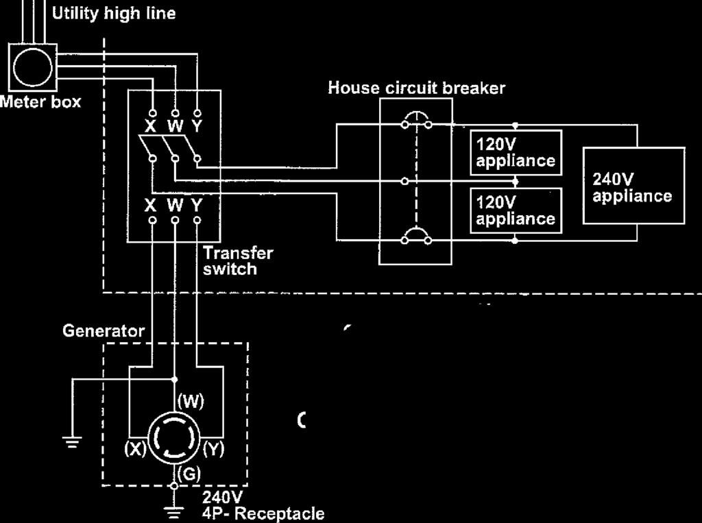
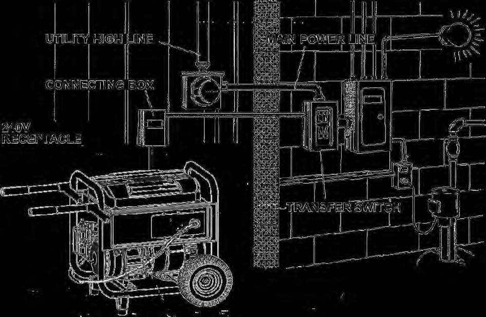
14 GFCI RECEPTACLE After starting the engine, check the GFCI for proper functioning by the following test procedure. Push the TEST button, The RESET button will pop out exposing the word TRIP. Power is now off at the outlets protected by the GFCI, indicating that the device is functioning properly. If TRIP dose not appear when testing, do not use the generator. Call a qualified electrician. To restore power, push RESET button. If the RESET button pops out during operation, stop the generator immediately and call a qua lified electrician for checking generator and a ppliances. CONNECTING TO DOMESTIC CIRCUIT (HOUSE WIRING) This generator is neutral bonded type. If a generator is to be connected to residential or commercial power lines, such as a stand by power source during power outage, all connections must be by a licensed electrician. Failure in connection may result in death, personal injury,damage to generator, damage to a ppliances, damage to the building's wiring or fire. (a) When connecting a Subaru generator to a house wiring, generator output power must be taken from the 240V-4P receptacle. (b) Install a transfer switch. A transfer switch must be installed to transfer the load from the commercial power source to the generator. This switch is necessary to prevent accidents caused by the recovery from power outage. Use a transfer switch of the correct capacity. Install transfer switch between the meter and the fuse or AC breaker box. [CAUTION] IF the neutral wire of house wiring is grounded, be sure to ground the ground terminal of the generator, Otherwise an electric shock may occur to the operator


15 - 13 -
16 5. MEASURING PROCEDURES 5-1 MEASURING INSTRUMENTS (1) VOLTMETER AC voltmeter is necessary. The approximate AC voltage ranges of the voltmeters to be used for various types of generators are as follows : 0 to 150 V : Type with an output voltage of 110 or 120 V 0 to 300 V : Type with an output voltage of 220, 230 or 240 V 0 to 150 V, 0 to 330 V : Dual voltage type (2) AMMETER AC ammeter is necessary. An AC ammeter with a range that can be changed according to the current rating of a given generator is most desirable. (About 10 A, 20 A, 100 A) (3) FREQUENCY METER Frequency range : About 45 to 65Hz NOTE : Be careful of the frequency meter's input voltage range
17 (4) CIRCUIT TESTER Used for measuring resistance, etc. (5) MEGGER TESTER Used for measuring generator insulation resistance. Select one with testing voltage range of 500V. (6) TACHOMETER Use the contactless type tacho meter

18 5-2 AC OUTPUT MEASURING Use a circuit above for measuring AC output. A hot plate or lamp with a power factor of 1.0 may be used as a load. Adjust the load and rpm. and check that the voltage range is as specified in the following table at the rated amperage and rated rpm. model Rated voltage 240V-60Hz SGX SGX SGX Voltage range 5-3 MEASURING INSULATION RESISTANCE Use a megger tester to check the insulation resistance. Remove the control panel, and disconnect the connector of GREEN lead for ground. Connect a megger tester to one of receptacle output terminals and the ground terminal, then measure the insulation resistance

 STATOR Measure the insulation resistance between each lead wire and the core.")
 CONTROL PANEL Measure the insulation resistance between the live parts and the grounded parts.")
19 An insulation resistance of 1 megohm or more is normal. (The original insulation resistance at the time of shipment from the factory is 10 megohm or more.) If it is less than 1 megohm, disassemble the generator and measure the insulation resistance of the stator, rotor and control panel individually. (1) STATOR Measure the insulation resistance between each lead wire and the core. (2) ROTOR Measure the insulation resistance between the slip ring and the core. (3) CONTROL PANEL Measure the insulation resistance between the live parts and the grounded parts. Any part where the insulation resistance is less than 1MΩ has faulty insulation, and may cause electric leakage and electric shock. Replace the faulty part

 6-2 CIRCUIT BREAKER Check continuity between each of two terminals at the rear of the circuit breaker while it is mounted on the control panel.")
 AC CIRCUIT BREAKER Frequency Rated output SGX3500 3200VA SGX5000 SGX7500 60Hz 4500VA 6700VA Max voltage 250V 250V 250V Rated fault current")
20 6. CHECKING FUNCTIONAL MEMBERS 6-1 RECEPTACLES Using a circuit tester, check continuity between the two terminals at the rear of the receptacles while the receptacle is mounted on the control panel. When continuity is found between the output terminals of the receptacle with a wire connected across these terminals, the receptacle is normal. When the wire is removed and no continuity is found between these terminals, the receptacles are also normal. CIRCUIT TESTER (Continuity test) 6-2 CIRCUIT BREAKER Check continuity between each of two terminals at the rear of the circuit breaker while it is mounted on the control panel. Normally, there is continuity between each of the two when the circuit breaker is on while there is no continuity when the circuit breaker is off. PUSH Type LEVER Type AC CIRCUI BREAKER (Type 1) AC CIRCUIT BREAKER Frequency Rated output SGX VA SGX5000 SGX Hz 4500VA 6700VA Max voltage 250V 250V 250V Rated fault current 18.75A 25A 37.5A AC CIRCUI BREAKER (Type 2) AC CIRCUIT BREAKER Frequency Rated output Rated voltage Rated fault current SGX Hz 6700VA 125V 20A

 (Ω) SGX3500 SGX5000 SGX7500 FREQUENCY 60Hz RATED VOLTAGE 120V/240V AC WINDING 1 BLACK1-WHITE 0.481 0.26 0.18 AC WINDING 2 BLACK2-WHITE 0.487 0.26 0.18 SUB COIL Blue-Blue 2.")
21 6-3 STATOR Disengage connectors on the wires from stator and check the resistance between wires with a circuit tester referring to the following table. NOTE : If the circuit tester is not sufficiently accurate, it may not show the values given and may give erroneous readings. Erroneous readings will also occur when there is a wide variation of resistance among coil windings or when measurement is performed at ambient temperatures different from 20 C (68 F). B W W 1 2 *Ambient temperature at 20 (68 F ) (Ω) SGX3500 SGX5000 SGX7500 FREQUENCY 60Hz RATED VOLTAGE 120V/240V AC WINDING 1 BLACK1-WHITE AC WINDING 2 BLACK2-WHITE SUB COIL Blue-Blue HOUR MATER COIL Red-White AC WINDING 1 Green-Black ROTOR ASSEMBLY 1) Field coil Remove the brush holder and measure resistance between the slip rings. *Ambient temperature at 20 (68 F ) ROTOR (SLIP RING) SGX Hz-120/240V 48.5 SGX SGX NOTE : If the circuit tester is not sufficiently accurate, it may not show the values given and may give erroneous readings. Erroneous reading will also occur when there is a wide variation of resistance among coil windings or when measurement is performed at ambient temperatures different from from 20 C (68 F). (Ω)

22 2) Cleaning Slip rings The slip ring surfaces must be uniformly bright. Slip rings showing black spots, excessive wear, or uneven wear must be repaired. A stained slip ring lowers generator efficiency and output voltage. Polish the slip rings with fine sandpaper while turning the rotor until rough spots disappear. Care should be taken not to touch the rotor coils with the sandpaper. 6-5 BRUSH The brushes must be smooth where they contact the slip rings. If not, polish smooth the brushes with sandpaper. A brush that is not smooth produces arcs between the brush and slip ring leading to possible damage. Usable brush lengths are from 5 mm to 11 mm (0.20 " to 0.43"). A brush shorter than 5 mm must be replaced because decreased contact pressure between the brush and slip ring lowers generator efficiency and output voltage. 6-6 A.V.R.. (AUTOMATIC VOLTAGE REGULATOR) 1) Features This A.V.R. operates to control the field current in order to maintain the output voltage for the AC current, which generated by the magnetic flux by the field coil. 2) A.V.R. trouble may be identified by simply looking at the A.V.R., or by the inter-lead resistance with a tester, or actually mounting it in the generator and operating it

23 (a) A.V.R. TROUBLE IDENTIFICATION by APPEARANCE If an A.V.R. electronic part is burnt dark, or the surface epoxy resin melted, it often indicates A.V.R. trouble. (b) IDENTIFYING A.V.R. TROUBLE by CHECKING INTER-LEAD RESISTANCE Check the inter-lead resistance of the A.V.R. with a tester, referring to the following table. If the tester readings very greatly from the values specified in the table on next page, the A.V.R. is faulty. NOTE : Take tester inaccuracy into account in reading the tester (c) IDENTIFYING A.V.R. TROUBLE by MOUNTING and OPERATING in THE GENERATOR SCR or transistor damage cannot be detected by simply looking at the A.V.R. or checking the lead resistance. Check it by mounting the suspectedly faulty A.V.R. in a normal generator, or mount a normal A.V.R. in a generator which fails to generate voltage. *Chacking table for analogue circuit tester (Resistance). (Ω)(R±20%) SGX3500/5000 apply black 一 needle of the circuit tester (60Hz-120/240V) Black Red White-1 White-2 Blue-1 Blue-2 Black 407K 6.07M 5.66M 5.12M 5.20M Red 5.47M 9.42M 9.72M 9.50M 9.68M Apply red 十 needle White M 6.90M 7.0M 6.75M 6.90M of the circuit tester White M 6.10M 6.2M 6.09M 6.25M Blue M 2.54M 12M 12.25M 12.18M Blue M 2.95M 12.45M 12.69M 11.92M (Ω)(R±20%) apply black 一 needle of the circuit tester SGX7500(60Hz-120/240V) Green Red Yellow-1 Yellow-2 Blue-1 Blue-2 Green 22.33k 2.88M 2.90M 2.52M 3.40M Red 23K 3.13M 3.17M 2.73M 3.60M Apply red 十 needle Yellow M 2,95M 5.41M 5.70M 6.56M of the circuit tester Yellow M 2.86M 6.02M 5.53M 6.40M Blue M 2.72M 5.98M 5.96M 13.5M Blue M 2.56M 13.06M 12.88M 12.3M
24 6-8 OIL SENSOR (1) Disconnect wires coming from the sensor at the connection. (2) Loosen the sensor to remove it from the engine. (3) Plug the opening of oil filler hole (created after sensor is removed) with suitable means such as oil gauge. (4) Connect the removed wires again with the oil sensor. (5) Start the engine with the oil sensor removed and confirm if ; a. Engine stops after 5 seconds which is normal, or b. Engine does not stop after more than 10 seconds which is unusual. NOTE : The sensor will not operate properly when wire is broken or poorly connected. Check the wires for correct connection. If it fails to stop within 5 seconds after the wirings have checked, the sensor is wrong. Replace the sensor with new one CONSTRUCTION AND OPERATION Disconnect wires coming from the sensor. The oil sensor is composed of the float, permanent magnet incorporated into the float and the oil sensor. In accordance with the oil level, the float moves up and down. When the oil level is upper level, the float moves up. When the oil level is lower level, the float moves down. The premanent magnet is close to the lead switch, and the lead switch is activated by the magnetic force. NOTE: With regards to the wiring diagram, please refer to the section 9 (Page 43)

 To prevent bolts and nuts from being misplaced or installed incorrectly, replace them temporarily to their original position.")
25 7. DISASSEMBLY AND ASSEMBLY 7-1 PREPARATION and PRECAUTIONS (1) Be sure to memorize the location of individual parts when disassembling the generator so that the generator can be reassembled correctly. Tag the disassembled part with the necessary information to facilitate easier and smoother reassembly. (2) For more convenience, divide the parts into several groups and store them in boxes. (3) To prevent bolts and nuts from being misplaced or installed incorrectly, replace them temporarily to their original position. (4) Handle disassembled parts with care; clean them before reassembly using a neutral cleaning fluid. (5) Remove the battery before disassembling the generator. (Electric start models) (6) Use all disassembly/assembly tools properly, and use the proper tool for each specific job. (7) Be sure to attach the foam rubber linings inside the covers on their original position when reassembling the generator. When deformation or damage or falling-off of foam rubber lining is found, replace it with new part. Failure to do so will result in poor performance and durability of the generator. (8) Bind the wires and fuel pipes using wire bands as they have been done in original configuration. NOTE : As to detailed information for servicing procedures on engine portion, please refer to Subaru engine service manual for "EX series". 7-2 DISASSEMBLY PROCEDURES FUEL TANK (1) Shut the fuel valve and discharge fuel from fuel tank and carburetor. (2) Disconnect rubber pipe from the strainer. (3) Remove the fuel tank. M6 flange bolt and nut... 4 pcs MUFFLER (1) Remove the Muffler Cover. Tapping screw pcs. M5 Flange bolt and nut pcs

 SGX3500")


 Remove the control box.")
 Loosen the control panel.")
26 (2) Loosen flange bolt and nut for the muffler stay. 5/16-18 x PC (SGX3500) 5/16-24 x PCS (SGX5000 / 7500) SGX3500 SGX5000 / 7500 (3) Remove the muffler from Exhaust pipe CONTROL BOX (1) Remove the end cover. M6 flange bolt... 2 pcs. (2) Disconnect the connectors on the wiring from the alternator. (3) Remove the wiring terminals from wiring board and disconnect all wiring from control box. (4) Remove the control box. M4 screw... 4pcs (5) Loosen the control panel. M4 screw... 2pcs BRUSH HOLDER EARTH TREMINAL AVR UNIT WIRING BOARD
 Set the generator set with the rear cover upwards.")
 Remove the two flange nuts (SGX3500: bolt) fixing rear cover onto the")
 Remove the stator NOTE) The rear cover and the stator are clamped")

-2 Loosen the bolt and nut.")
-3 Remove the rear cover (4)-4 Remove the stator cover with claws")
27 7-2-4 ALTERNATOR (1) Remove the AVR unit, brush holder. (2) Set the generator set with the rear cover upwards. NOTE) Before starting this work, make sure engine oil has been discharged. (3) Remove the two flange nuts (SGX3500: bolt) fixing rear cover onto the mount rubbers. M8 flange nut (bolts)... 2 pcs. (4) Remove the stator NOTE) The rear cover and the stator are clamped together by two of M6 bolts and nuts. Do not loosen these bolts prior to being removed of the rear cover united with the stator. (4)-1 Remove the rear cover united with the stater. Flange bolt M pcs. Do not loosen. (4)-2 Loosen the bolt and nut. (united the rear cover with the stator). Bolt M pcs. (4)-3 Remove the rear cover (4)-4 Remove the stator cover with claws (2pcs) Raised up by using screw driver. NOTE) The stator is heavy. Be careful do not hit the coil of the stator to the rotor
 3.")
28 (5) Take off the through bolt of the rotor. SGX3500 M8 X 195mm SGX5000 M8 X 195mm SGX7500 M8 X 252mm (10) Use a bolt and oil as a tool for pulling out rotor in the following procedures : 1. Pour engine oil into the center hole of rotor shaft. Fill with oil to the shaft end. 2. Prepare a bolt with the following thread size : M (SGX3500/5000/7500) 3. Apply a few turns of seal tape around the tip of the bolt 4. Screw the bolt into the thread of the rotor shaft. 5. Torque the bolt using a socket wrench until the rotor comes off loose. * The hydraulic pressure inside the rotor shaft takes apart the rotor from the engine shaft (11) Remove the front cover. M8 20 flange bolt... 4 pcs
29 7-3 COMPONENT PARTS
30 - 28 -
31 - 29 -
32 - 30 -
33 (3) Frame and accessories NOTE : Do not put fuel or lubricant in the generator before installing the feet, wheels and handles. INSTALLING THE WHEELS Wheels are provided to assist in moving the generator to the desired location and should be installed on the opposite side of the handle Locate the following items: 2 Bolts(3/ /4in.) 2 Washers(3/8 in.) 2 Spacers(0.38in.ID) 2 Wheels 2 Lock nuts(3/8-16) Tightening torque: 8 to 12N m (80 to 120kg cm) Locate the following items: 2 Rubber feet 2 Rubber support 2 Lock nuts(1/4-20) 2 Washers(M6) 2 Bolts(1/ mm) Tightening torque: 2 to 3N m (20 to 300kg cm) NOTE: Be careful not to over tighten so that foot material collapses. Repeat with remaining foot. Locate the following items: 2 Handles 2 Bolts(5/ /4in.) 2 Washers(5/16in.) 2 Lock nuts(5/16in.) 2 Nylon washer(5/16in.) Tightening torque: 4 to 6N m (40 to 60kg cm) 2 Handle lock pins 2 Lanyards


34 7-4 ASSEMBLY PROCEDURES ENGINE and FRAME (1) Attach the mount rubbers to the frame. Insert the setting tongue of mount rubber into the hole on the frame and tighten the nut from the bottom of the frame. M8 flange nut... 4 pcs. SGX3500 SGX5000 / 7500 NOTE : The mount rubbers are selected to reduce vibration most effectively by model. Be sure to use the correct mount rubber for your generator. Although mount rubbers have the same appearance, their characteristics are different. (2) Install the engine into the frame from the side of it. Tighten the nuts over the mount rubber bolts to fix


35 NOTE : Tighten nut together with air cleaner bracket in air cleaner side. (SGX3500 / 5000) SGX3500 / 5000 M8 flange nut... 2 pcs. NOTE : Remove the air cleaner cover for easier installation. NOTE : When tightening the nuts, slightly lift the engine so that the weight is not applied to the mount rubbers. (3) Install the engine into the frame from the side of it. Insert the bolt of mount rubbers into the hole on the mount base. Tighten the nuts over the mount rubber bolts to fix. M8 nut/washer/lock washer... 2 pcs ea. Tighten the temporally fixed bolt and nut for mount base. NOTE : When tightening the nuts, slightly lift the engine so that the weight is not applied to the mount rubbers

 Wipe off oil, grease and dust from the tapered portion of engine shaft and")

36 7-4-3 FRONT COVER (1) Attach the front cover to the engine main bearing cover. SGX3500 5/16-24 flange bolt... 4 pcs. SGX 5000 / /8-16 flange bolt... 4 pcs ROTOR (1) Wipe off oil, grease and dust from the tapered portion of engine shaft and matching tapered hole of rotor shaft. (2) Mount the rotor to the engine shaft. Tighten the through bolt. flange bolt... 1 pc STATOR (1) Put the rear cover on the stator and pull out the stator wirings through the opening of the rear cover. (2) Tighten the stator and the rear cover With flange bolt and nut
 Fix the rear cover with flange bolts. flange bolt... 4 pc. NOTE : Tighten the bolts evenly and in turns.")
 Install the brush holder, AVR unit and wiring board in the rear cover. M5 16 bolt... 5 pcs.")

 Connect the earth (ground) wire (green) with the rear cover at earth terminal with screw and washer.")
37 (3) Put on the stator with rear cover evenly with a plastic hammer to press the rotor bearing into the rear cover. (3) Fix the rear cover with flange bolts. flange bolt... 4 pc. NOTE : Tighten the bolts evenly and in turns. (SGX3500: Bolt) (4) Set the mount rubber bolts into the rear cover holes. Do not tighten the nut at this moment. (5) Install the brush holder, AVR unit and wiring board in the rear cover. M5 16 bolt... 5 pcs. (AVR unit, brush holder, wiring board) NOTE : If the brush is installed oblique to the slip ring, there is possibility that the brush holder can break when the screw is tightened : or the brush may break when generator of started. Make this process carefully. (6) Attach the connectors to the brush holder, AVR unit. (7) Set the wires on the wiring board and tighten with washers and nuts. (8) Connect the earth (ground) wire (green) with the rear cover at earth terminal with screw and washer. (9) Connect earth (ground) wire between frame and rear cover mount rubber nut (bolt). On frame side: M6 12 bolt... 1 pc. (commonly tighten the mount rubber bolt) BRUSH HOLDER EARTH TREMINAL AVR UNIT WIRING BOARD
. (11) Attach the end cover to the rear cover. M5 8 bolt.")
 Mount the Exhaust pipe and")
38 (10) Set stator cover with the claw inserted into slit and bent (2 pcs). (11) Attach the end cover to the rear cover. M5 8 bolt... 2 pcs MUFFLER and MUFFLER COVER (1) Mount the Exhaust pipe and the gasket on the cylinder head. M8 flange nut... 2 pcs

 Assemble the duct. M6 12 flange bolt... 3 pcs.")

39 (3) Temporally attach the muffler and gasket to the exhaust pipe. Temporally attach the muffler bracket 2 to After that, tighten the nuts and flange bolts. M8 flange nuts... 2 pcs. (exhaust pipe) 5/16-24 x 16 flange bolt... 2 pcs. SGX3500 5/16-18 x 38 bolt, nut and washer (1pc). (4) Assemble the duct. M6 12 flange bolt... 3 pcs. (5) Attach the muffler cover to the flame. Temporally attach the muffler cover to the Home. Tapping screw pcs. M5 12 flange bolt and nut... 2 pcs

, then tighten the lock")


40 7-4-7 FUEL TANK (1) Hand tighten the strainer screw as far as it will go, loosen it again by one or two rotations (fuel outlet faces down), then tighten the lock nut. (2) Mount the fuel tank on the frame. M6 x 25 mm flange bolt... 4 pcs. Washer M pcs. Spacer... 4 pcs. Tank mounting rubber... 4 pcs. Locking nut pcs. NOTE : For easy tank assembly, glue the rubber washers over the mounting holes of the frame
 Mount the control panel together with the control box (Control box Assembly) onto the frame. M4 12 mm flange bolt... 2 pcs.")

 Remove the end cover and disconnect the wires to the control panel. (2) Remove the control box from the frame and remove the control panel.")

41 7-4-8 CONTROL BOX ASSY (1) Pass wires drawn out generator and engine to the control box. (2) Connect the wires coming from the control panel with wires coming from generator and engine. NOTE : Connect the wires of the same color. (3) Mount the control panel together with the control box (Control box Assembly) onto the frame. M4 12 mm flange bolt... 2 pcs. (4) Install the control box onto the frame. M4 12 mm flange bolt... 4 pcs. 7-5 CHECKING, DISASSEMBLY and REASSEMBLY of the CONTROL PANEL CHECKING OF THE CONTROL PANEL Dismount the control box assy. from frame. Remove the control box from control panel and check each components and wiring. Refer to Section 6 for the detail of checking procedure for the components in the front panel DISASSEMBLY (1) Remove the end cover and disconnect the wires to the control panel. (2) Remove the control box from the frame and remove the control panel. (3) After disconnecting individual wires, remove the control panel components REASSEMBLY (1) Install the receptacles, circuit breakers, terminals, switches, etc. on the control panel and wire them. NOTE : Circuit diagrams are shown in Section 9. Colored wires are used for easy identification, and are of the correct capacity and size. Use heat-resistant type wires (permissible temperature range 75 C or over) in the specified gauge shown in the circuit diagrams. (2) Connect the wires of control panel components. (3) Attach the control panel and control box to the frame. (Refer to for details.)
42 8. TROUBLESHOOTING 8-1 NO AC OUTPUT CHECKING STATOR (1) Remove control panel and disconnect stator wires at the connectors. (2) Measure the resistance between terminals on stator leads. Refer to Table of Section 6-3 STATOR for normal resistance. If stator is faulty, replace it with a new one. (3) Check the insulation resistance between stator core and each stator lead using a megger tester. If insulation is bad, replace stator with a new one CHECKING ROTOR 1) Field coil Remove the brush holder and measure resistance between the slip rings. Refer to Section 6-4 ROTOR ASSEMBLY for normal Resistance NOTE : If the circuit tester is not sufficiently accurate, it may not show the values given and may give erroneous readings. Erroneous reading will also occur when there is a wide variation of resistance among coil windings or when measurement is performed at ambient temperatures different from from 20 C (68 F)
43 2) Cleaning Slip rings The slip ring surfaces must be uniformly bright. Slip rings showing black spots, excessive wear, or uneven wear must be repaired. A stained slip ring lowers generator efficiency and output voltage. Polish the slip rings with fine sandpaper while turning the rotor until rough spots disappear. Care should be taken not to touch the rotor coils with the sandpaper. 3) Checking brush Check brush referring to STEP AC VOLTAGE IS TOO HIGH OR TOO LOW CHECKING ENGINE SPEED If the engine speed is too high or too low, adjust it to the rated r.p.m. [How to adjust engine r.p.m.] * Loosen the lock nut on the adjusting screw. * Turn the adjusting screw clockwise to decrease engine speed or counterclockwise to increase engine speed CHECKING STATOR Check stator referring to Step CHECKING ROTOR Check rotor referring to Step


 Measure the insulation resistance between the live terminal of the receptacle and the ground terminal.")
44 8-3 AC VOLTAGE IS NORMAL AT NO-LOAD, BUT THE LOAD CANNOT BE APPLIED CHECK THE ENGINE SPEED. If the engine speed is low, adjust it to the rated r.p.m. *Refer to Step for engine speed adjustment CHECK THE TOTAL WATTAGE OF APPLIANCES CONNECTED TO THE GENERATOR. Refer to Section 4 RANGE OF APPLICATIONS for the wattage of the appliances. If the generator is overloaded, reduce the load to the rated output of the generator CHECK THE APPLIANCE FOR TROUBLE. If the appliance is faulty, repair it CHECK IF THE ENGINE IS OVERHEATED. If the cooling air inlet and/or cooling air outlet is clogged with dirt, grass, chaff or other debris, remove it CHECK THE INSULATION OF THE GENERATOR. (1) Stop the engine. Remove the control panel, and disconnect the connector of GREEN lead for ground. (2) Measure the insulation resistance between the live terminal of the receptacle and the ground terminal. If the insulation resistance is less than 1MΩ, disassemble the generator and check the insulation resistance of the stator, rotor and the live parts in the control box. (Refer to Section 5-4.) Any part where the insulation resistance is less than 1MΩ, the insulation is faulty and may cause electric leakage. Replace the faulty part

45 9. WIRING DIAGRAM SGX
46 - 44 -
FUJI HEAVY INDUSTRIES LTD.
 RGX6500 RGX7500 FUJI HEAVY INDUSTRIES LTD. 1 2 1. SPECIFICATIONS 3 2. PERFORMANCE CURVES RGX6500 60Hz 240V RGX7500 60Hz 240V 4 3. GENERAL DESCRIPTION Canister?? 5 CONTROL PANEL 50Hz-220V, 240V, 60Hz-220V,
SERVICE MANUAL RGX2900 RGX3600 RGX4800 GENERATORS. Models. PUB-GS2102 Rev. 05/06
 SERVICE MANUAL Models RGX2900 RGX3600 RGX4800 GENERATORS PUB-GS2102 Rev. 05/06 CONTENTS Section Title Page 1. SPECIFICATIONS 1-1 SPECIFICATIONS.................................................. 1 1-2
PRO6.4, PRO6.4E, PRO9.0, PRO9.0E Generator Service Manual
 PRO6.4, PRO6.4E, PRO9.0, PRO9.0E Generator Service Manual IMPORTANT: Read all safety precautions and instructions carefully before operating equipment. Ensure equipment is stopped and level before performing
GEN 5.0 Generator Service Manual
 GEN 5.0 Generator Service Manual IMPORTANT: Read all safety precautions and instructions carefully before operating equipment. Refer to operating instruction of equipment that this engine powers. Ensure
SERVICE MANUAL COMMERCIAL GENERATOR REV 11/06
 SERVICE MANUAL COMMERCIAL GENERATOR PX4800/e & 6100/e 0914-0504 REV 11/06 CONTENTS Section Title Page 1. SPECIFICATIONS... 1 2. PERFORMANCE CURVES... 3 3. FEATURES... 5 3-1 BRUSHLESS ALTERNATOR... 5 3-2
SERVICE MANUAL R1100 GENERATORS. Models. PUB-GS2363 Rev. 04/07
 SERVICE MANUAL Models R1100 GENERATORS PUB-GS2363 Rev. 04/07 CONTENTS Section Title Page 1. SPECIFICATIONS..................................................... 1 1-1 SPECIFICATIONS..................................................
Electrical Energy and Power Ratings
 Section 1 - From the Wall Socket Electrical Energy and ower Ratings Batteries and the mains are sources of electrical energy. Electrical appliances can then convert this into other forms of energy. e.g.
HEAVY DUTY POWER RELAYS FEATURES
 VDE VC HEAVY DUTY POWER RELAYS VC RELAYS Faston terminal Screw terminal mm 9 FEATURES VC power relays are designed for controlling heavy duty loads safely: Contact gap of 3 mm or more -point contacts for
SGB12000HX PORTABLE GENERATOR
 12KWG022004KOD PRINTED IN CANADA SGB12000HX PORTABLE GENERATOR OPERATING INSTRUCTIONS AND PARTS MANUAL John Brooks Company Limited Mississauga, Ontario L5N 7K5 12 1 Troubleshooting The majority of problems
RigMaster Power Service and Repair Manual Document # S901009
 Document # S901009 WARNING The following procedures present hazards which can result in injury or death. Only persons qualified to carry out electrical and mechanical servicing should undertake this work.
DC MOTOR MAINTENANCE ALL ELECTRIC LIFT TRUCKS PART NO SRM 294
 DC MOTOR MAINTENANCE ALL ELECTRIC LIFT TRUCKS PART NO. 897076 620 SRM 294 SAFETY PRECAUTIONS MAINTENANCE AND REPAIR When lifting parts or assemblies, make sure all slings, chains, or cables are correctly
SUBMERSIBLE PUMP HSE RANGE
 SUBMERSIBLE PUMP HSE RANGE OPERATION & MAINTENANCE INSTRUCTIONS 0806 SPECIFICATIONS Model No. HSE120* HSE200 HSE300*/ HSE360*/ HSEC400* HSE301 HSE361 Outlet Dia. (mm/inches) 32/1-1/4 38/1-1/2 50/2 50/2
PL Submersible, Semi-Vortex, Water Feature Pump
 TM M 2001992 Introduction Submersible, Semi-Vortex, Water Feature Pump This manual provides information and procedures to safely install, operate and maintain this TSURUMI model. For your own safety and
SUBMERSIBLE PUMP HSE RANGE
 SUBMERSIBLE PUMP HSE RANGE OPERATION & MAINTENANCE INSTRUCTIONS 0707 SPECIFICATIONS HSE300* HSE360* Model No. HSE130* HSE200A HSE300A HSE360A HSEC400* HSE301A HSE361A Outlet Dia. (mm/inches) 32/1-1/4 38/1-1/2
Electrical Equipment and Terminology
 Youth Explore Trades Skills Description Understanding the language of the electrical trade and knowing what electrical equipment is named and its purpose are very important. Anyone who is exposed to a
SERVICE MANUAL RGX2900 RGX3600 RGX4800 GENERATORS. Models. PUB-GS2377 Rev. 06/08
 SEVICE MANUAL Models GX2900 GX3600 GX4800 GENEATOS PUB-GS2377 ev. 06/08 CONTENTS Section Title Page 1. SPECIFICATIONS 1-1 SPECIFICATIONS.................................................. 1 1-2 PEFOMANCE
MANUAL. RGVl2000 /13OOOT GENERATORS. Models. PUB-GS1328 Rev. Ol/OO
 MANUAL Models RGVl2000 /13OOOT GENERATORS PUB-GS1328 Rev. Ol/OO o......... CONTENTS Section Title Page l l l l l l l l l l l l l l l l l l 4.CONSTRUCTlONANDFUNCTlON 4-l CONSTRUCTlON.............................
User s Manual. Automatic Switch-Mode Battery Charger
 User s Manual Automatic Switch-Mode Battery Charger IMPORTANT Read, understand, and follow these safety rules and operating instructions before using this battery charger. Only authorized and trained service
Art. No. EC-315. Art. No. EC-330. Art. No. EC-340 SWITCH-MODE BATTTERY CHARGER CONTENTS IMPORTANT SAFETY PRECAUTIONS... 2
 SWITCH-MODE BATTTERY CHARGER CONTENTS IMPORTANT SAFETY PRECAUTIONS... 2 DESCRIPTION AND FEATURES... 3 CHARGING STAGES... 4 Art. No. EC-315 Art. No. EC-330 Art. No. EC-340 PROTECTIONS... 5 INSTALLATION...
section-page Table 1. Transfer switching device ratings. Conditional short circuit current
 Operator s Manual 7000 Series ATS Automatic Transfer Switching Equipment D design 30 through 200 amperes TABLE OF CONTENTS section-page INSTALLATION... 1-1 Enclosures and Mounting... 1-1 Power Connections...
OPERATING AND MAINTENANCE INSTRUCTIONS. Generator Models SXA1900HX, SXA2800HX,SXB2800HX SXB4000HX, SXB5500HX(S), SXB7000HX(S)
, SXB7000HX(S)") GASOLINE POWERED PORTABLE GENERATORS OPERATING AND MAINTENANCE INSTRUCTIONS Generator Models SXA1900HX, SXA2800HX,SXB2800HX SXB4000HX, SXB5500HX(S), SXB7000HX(S) JOHN BROOKS COMPANY LIMITED TORONTO - MONTREAL
GASOLINE POWERED PORTABLE GENERATORS OPERATING AND MAINTENANCE INSTRUCTIONS Generator Models SXA1900HX, SXA2800HX,SXB2800HX SXB4000HX, SXB5500HX(S), SXB7000HX(S) JOHN BROOKS COMPANY LIMITED TORONTO - MONTREAL
CHARGING SYSTEM PRECAUTION CH 1
 1NZ-FE ARGING ARGING SYSTEM ARGING SYSTEM PRECAUTION 1 1. Check that the battery cables are connected to the correct terminals. 2. Disconnect the battery cables when the battery is given a quick charge.
Florham Park, NJ USA Call (ASCO) for sales or service
 for sales or service") Operator s Manual 4000 Series ATS Automatic Open-Transition Transfer Switches D design 30 230A, J design 260 600A, H-design 800 1200A, G-design 1600 4000A, F-design 4000A DANGER is used in this manual
Operator s Manual 4000 Series ATS Automatic Open-Transition Transfer Switches D design 30 230A, J design 260 600A, H-design 800 1200A, G-design 1600 4000A, F-design 4000A DANGER is used in this manual
Florham Park, NJ USA Call (ASCO) for sales or service
 for sales or service") Operator s Manual 7000 Series ATS Automatic Transfer Switches D design, 30 through 230 A DANGER is used in this manual to warn of a hazard situation which, if not avoided, will result in death or serious
Operator s Manual 7000 Series ATS Automatic Transfer Switches D design, 30 through 230 A DANGER is used in this manual to warn of a hazard situation which, if not avoided, will result in death or serious
L-SERIES PUMPS. Operating Manual. Includes Pumps: L-305 L PONDS
 L-SERIES PUMPS Operating Manual Includes Pumps: L-305 L-310 1-877-80-PONDS www.atlanticwatergardens.com Introduction Thank you for selecting the TidalWave L-305/L-310 series pumps. Before using this pump
Using Electricity. Summary Notes. 1. From the Wall Socket Household appliances. Earth wire and safety.
 Using Electricity Summary Notes Section Content 1. From the Wall Socket Household appliances. Earth wire and safety. 2. Alternating and Direct Battery and transformer. Current Circuit diagrams. Current
Matala. VersiFlow Series. Instruction and Maintenance Manual
 VersiFlow Series High Flow Multi-Purpose "Versatile " Pump V-3200 1/5HP 150W / Discharge 2 V-3900 1/3HP 250W / Discharge 2 V-4700 1/2HP 400W / Discharge 2 V-5600 1HP 750W / Discharge 2 Instruction and
Installation Operation Parts
 OWNER S MANUAL BATTERY BACKUP SUMP Installation Operation Parts For further operating, installation or maintenance assistance, Call 98-8-05 PRINTED IN U.S.A. M-8 (/9) RULES FOR SAFE INSTALLATION AND OPERATION
Maintenance Information
 Form 16575334 Edition 1 April 2005 Electric Screwdrivers EL, EP and ET 34V DC Series Maintenance Information Save These Instructions WARNING Maintenance procedures have the potential for severe shock hazard
LDG6000SA DIESEL GENERATOR OWNERS MANUAL
 LDG6000SA DIESEL GENERATOR OWNERS MANUAL BEFORE OPERATING THIS EQUIPMENT PLEASE READ THESE INSTRUCTIONS CAREFULLY Preface Thank-you for purchasing this generator. This operation manual contains information
MMA 160S ARC/MMA WELDER OPERATION INSTRUCTIONS
 www.r-techwelding.co.uk MMA 160S ARC/MMA WELDER OPERATION INSTRUCTIONS 2 Thank you for selecting the R-Tech MMA160S Inverter Arc Welder. The MMA160S has many benefits over traditional Arc welders, including
Electric motor testing
 Electric motor testing MOTOR (MODELS EJ4-4001 AND EJ8-4001A) 23 GENERAL INFORMATION The vehicle is equipped with a 48-volt DC, shunt-wound, reversible traction motor. The shunt-wound motor is designed
2015 EDITION SUBMERSIBLE MOTORS AIM MANUAL. APPLICATION INSTALLATION MAINTENANCE 60 Hz, Single-Phase and Three-Phase Motors. franklinwater.
 0 EDITION AIM MANUAL SUBMERSIBLE MORS APPLICATION INSTALLATION 60 Hz, Single-Phase and Three-Phase Motors franklinwater.com All Motors System Troubleshooting Motor Does Not Start A. No power or incorrect
GeyserMax-Flow Series
 GeyserMax-Flow Series 115V/60Hz Waterfall Pump GM-3900 1/5HP 150W / Discharge 1-1/2 GM-4700 1/3HP 250W / Discharge 2 GM-5400 1/2HP 400W / Discharge 2 GM-6200 3/4HP 750W / Discharge 2 230V/50Hz GM-3800
Installation Manual. D3600- Series Duplex Grinder Systems. Contents
 Installation Manual 7353000E D3600- Series Duplex Grinder Systems Features: 36 Diameter Fiberglass Tank Available in 48, 60, 72, 84, and 96 heights LSG Single or LSGX 2 Stage 2HP Grinder Pumps Factory
ISP-500B. Oil-free Scroll Vacuum Pump. Instruction Manual. View our inventory. Record of Pump Information. Serial Number: Purchase date:
 ISP-500B Oil-free Scroll Vacuum Pump Instruction Manual View our inventory Serial Number: Record of Pump Information Purchase date: In Service date: Dealer information: IM-500B 1/3/07 Page 1 of 26 Important
SEWAGE PUMP MODEL # Zoeller is a registered trademark of Zoeller Co. All Rights Reserved. Español p. 14
 SEWAGE PUMP Zoeller is a registered trademark of Zoeller Co. All Rights Reserved. MODEL #1261-0001 Español p. 14 ATTACH YOUR RECEIPT HERE Serial Number Purchase Date Questions, problems, missing parts?
KE-4 Installation/Operation Instruction Manual FT033
 KE-4 Installation/Operation Instruction Manual FT033 Electronic Control System Electronic Control System Thumb Tab Guide Trolling Module Handheld Control Engine Synchronization Trolling Module Handheld
Commercial Series Generator Operator Manual (with Kohler Command series engines)
") Commercial Series Generator Operator Manual (with Kohler Command series engines) PN: 220880 PREFACE Thank you for purchasing a Wanco Commercial Series portable generator set. This manual contains important
Commercial Series Generator Operator Manual (with Kohler Command series engines) PN: 220880 PREFACE Thank you for purchasing a Wanco Commercial Series portable generator set. This manual contains important
INDEX Section Page Number Remarks
 INDEX Section Page Number Remarks Synchronous Alternators 2 4 General Fault Finding Capacitors 5 6 Fault Finding & Testing Diodes,Varistors, EMC capacitors & Recifiers 7 10 Fault Finding & Testing Rotors
Ph: (07) Fax: (07) Pump Manual
 Fax: (07) Pump Manual") sales@scintex.com.au www.scintex.com.au Ph: (07) 3137 0135 Fax: (07) 3041 0541 Pump Manual 12V 75LPM Vane Pump & Vane Pump Station SPEP12V75 & SP12VFS75 SPEP12V75 SP12VFS75 Parts List No. Part Name QTY
sales@scintex.com.au www.scintex.com.au Ph: (07) 3137 0135 Fax: (07) 3041 0541 Pump Manual 12V 75LPM Vane Pump & Vane Pump Station SPEP12V75 & SP12VFS75 SPEP12V75 SP12VFS75 Parts List No. Part Name QTY
92 V. FRAME. 2. Compress each rear shock absorber spring, pull the upper joint upward and secure with the spring seat stops.
 92 V. FRAME Assembly To assemble, reverse the disassembly procedures, paying attention to the following: 1. When the upper joints have been removed, apply a coat of thread locking agent to the tapped portion
PRE-PLUMBED SEWAGE SYSTEM
 PRE-PLUMBED SEWAGE SYSTEM Zoeller is a registered trademark of Zoeller Co. All Rights Reserved. MODEL #1910-0009 Español p. 13 ATTACH YOUR RECEIPT HERE Serial Number Purchase Date Questions, problems,
1RECHARGEABLE APPLIANCES
 1RECHARGEABLE APPLIANCES 1 CAUTION Certain rechargers for small nickel cadmium batteries can be damaged if connected to the unit. Two types of equipment are particularly prone to this problem: 1. Small
CHAPTER 22 STARTER Models J05C-TD, J08C-TP and TR
 1 INDEX STARTER 22-1 22-114E-03 CHAPTER 22 STARTER TROUBLESHOOTING...22-2 STARTER...22-4 22 22-2 STARTER 1 page 1 TROUBLESHOOTING Symptom Possible cause Remedy Engine does not crank, or cranks slowly Key
Maintenance Manual 13 AMPERE POWER SUPPLY 19A704647P1-P3. Mobile Communications LBI-31801C
 C Mobile Communications 13 AMPERE POWER SUPPLY 19A704647P1-P3 CAUTION THESE SERVICING INSTRUCTIONS ARE FOR USE BY QUALI- FIED PERSONNEL ONLY. TO AVOID ELECTRIC SHOCK DO NOT PERFORM ANY SERVICING OTHER
GRINDER PUMP MODEL # Zoeller is a registered trademark of Zoeller Co. All Rights Reserved. Español p. 13
 GRINDER PUMP Zoeller is a registered trademark of Zoeller Co. All Rights Reserved. MODEL #2701-0005 Español p. 13 ATTACH YOUR RECEIPT HERE Serial Number Purchase Date Questions, problems, missing parts?
ELECTRICAL INSTALLER EXAMINATION 18 November 2017 QUESTION AND ANSWER BOOKLET
 Candidate Code No. EIN15 For Board Use Only Result Date Int Result Date Int ELECTRICAL INSTALLER EXAMINATION 18 November 2017 QUESTION AND ANSWER BOOKLET INSTRUCTIONS READ CAREFULLY Time Allowed: Three
SERVICE SHOP NOTES. Use ohmmeter to check the resistance between the leads.
 SERVICE SHOP NOTES LIMA MAC SELF VOLTAGE REGULATED GENERATORS Troubleshooting Tips Symptom: Engine bogs down or stalls even at no load. Problem: Main stator has one or more taps wound or connected incorrectly.
Fault Finding. Standard/Fundamental Faults
 Fault Finding There is a generally recognised method of approaching faultfinding, which is referred to as the 5-Point Fault Finding approach... the most important factor in this method concerns attaining
3 Phase Smart Controller
 3 Phase Smart Controller Installation and Owner s Manual STP-SCIII 208-230 VAC, 60Hz, 120 Volt Coil Franklin Fueling 3760 Marsh Rd. Madison WI 53718 USA Tel: +1 608 838 8786 800 225 9787 Fax: +1 608 838
Automatic taper of charge rate for superior battery life through good equalization of cells and low water use rate.
 FEATURES Automatic taper of charge rate for superior battery life through good equalization of cells and low water use rate. Silicon diodes with inherent surge protection operated at a conservative percentage
INFO. SHEET: E1:1 INSPECTION & TESTING OF ELECTRICAL EQUIPMENT
 INFO. SHEET: E1:1 INSPECTION & TESTING OF ELECTRICAL EQUIPMENT This Information Sheet provides guidance on how to carry out User Checks, Formal Visual Inspections and combined Inspection and Tests on portable
Chapter 21 Practical Electricity
 Chapter 21 Practical Electricity (A) Electrical Power 1. State four applications of the heating effect of electricity. Home: o Used in electric kettles o Used in electric irons o Used in water heaters
Submersible Pumps Model ST4125D Model ST6125D
 OPERATION AND PARTS MANUAL Submersible Pumps Model ST5D Model ST65D Revision #0 (0/05/0) To find the latest revision of this publication, visit our website at: www.multiquip.com THIS MANUAL MUST ACCOMPANY
C.E. Niehoff & Co. C653/C653A and C625 Alternators Troubleshooting Guide NOTICE. Hazard Definitions. Battery Charge Volt and Amp Values
 C.E. Niehoff & Co. C653/C653A and C625 Alternators Troubleshooting Guide Hazard Definitions These terms are used to bring attention to presence of hazards of various risk levels or to important information
MODEL D 10YB POWER TOOLS TECHNICAL DATA AND SERVICE MANUAL ANGLE DRILL D 10YB SPECIFICATIONS AND PARTS ARE SUBJECT TO CHANGE FOR IMPROVEMENT
 MODEL D 10YB POWER TOOLS D ANGLE DRILL D 10YB TECHNICAL DATA AND SERVICE MANUAL LIST No. 0193 Jun. 2000 SPECIFICATIONS AND PARTS ARE SUBJECT TO CHANGE FOR IMPROVEMENT Notice for use Specifications and
OWNER S MANUAL AND INSTALLATION INSTRUCTIONS
 EmerGen Switch Manual Transfer Switch OWNER S MANUAL AND INSTALLATION INSTRUCTIONS For A Series Models 6-5001, 6-7501, 10-7501, 10-12K1 PLEASE READ THIS MANUAL IN ITS ENTIRETY BEFORE INSTALLING AND/OR
ALTERNATOR - BOSCH 35/75-AMP & 40/90-AMP
 ALTERNATOR - BOSCH 35/75-AMP & 40/90-AMP 1988 Chrysler LeBaron Convert/Coupe 1988 ALTERNATORS & REGULATORS Chrysler Motors - Bosch 35/75 & 40/90 Amp Alternator All Models DESCRIPTION The charging system
CHARGING SYSTEM ON-VEHICLE INSPECTION
 CHARGING (2UZFE) CHARGING SYSTEM CHARGING SYSTEM ONVEHICLE INSPECTION CH1 CH0J603 CAUTION: Check that the battery cables are connected to the correct terminals. Disconnect the battery cables when the battery
Models- 8105, Commercial Vacuums. Product Information Product Dimensions. Important Safety Instructions
 Models- 8105, 9225 9235 Commercial Vacuums Page 2 Page 3 Page 4 Page 5 Page 5-8 Page 9 Page 10 Page 10 Page 11 Page 12-19 Page 20-24 Product Information Product Dimensions Specifications Important Safety
OPERATION INSTRUCTIONS
 www.r-techwelding.co.uk Email: sales@r-techwelding.co.uk Tel: 01452 733933 Fax: 01452 733939 ProArc 175 INVERTER ARC WELDER OPERATION INSTRUCTIONS Version 2017-10 2 3 Thank you for selecting the R-Tech
1. General Description
 General Description 1. General Description A: SPECIFICATION Front Rear Model Wheel arch height (Tolerance: +12 mm 24 mm ( +0.47 in 0.94 in)) mm (in) 376 (14.8) Camber (Tolerance: 0 45 Differences between
operation manual Model Numbers MC3100PR MC6500ER MC9000ER
 operation manual Model Numbers MC3100PR MC6500ER MC9000ER table of contents Introduction 4 Using the Operators Manual Product Identification 5 Generator 5 Engine Safety 6 Safety Rules 6 Hazard Symbols
OWNER S MANUAL SELF-PRIMING PORTABLE UTILITY PUMP
 Model 54011-0 OWNER S MANUAL SELF-PRIMING PORTABLE UTILITY PUMP Questions, problems, missing parts? Before returning to the store call AQUAPRO Customer Service 8 a.m. - 5 p.m., EST, Monday-Friday 1-844-242-2475
ON-VEHICLE INSPECTION
 CH2 P11586 CHARGING CHARGING SYSTEM ONVEHICLE INSPECTION 1. CHECK BATTERY ELECTROLYTE LEVEL Check the electrolyte quantity of each cell. MaintenanceFree Battery: CH03L01 If under the lower level, replace
TECHNICAL INFORMATION
 TECHNICAL INFORMATION Model. Description DDF481 (XFD07*1) 18V Cordless driver drill *1 Model number for USA CONCEPT AND MAIN APPLICATIONS Model DDF481 (XFD07*1) is a supreme class cordless driver drill
03561 SPEED BOOSTER INSTRUCTION MANUAL. for the Ultra Tugger
 INSTRUCTION MANUAL NRTL/C LR 91904-8 03561 SPEED BOOSTER for the Ultra Tugger Read and understand all of the instructions and safety information in this manual before operating or servicing this tool.
STARTING SYSTEM (1ZZ FE) (April, 2003)
 (April, 2003)") STARTING & CHARGING STARTING SYSTEM (1ZZ FE) (April, 2003) STARTING SYSTEM (1ZZ FE) (April, 2003) INSPECTION 19 1 190QO 02 1. INSPECT STARTER ASSY NOTICE: These tests must be performed within 3 to 5 seconds
STARTING & CHARGING STARTING SYSTEM (1ZZ FE) (April, 2003) STARTING SYSTEM (1ZZ FE) (April, 2003) INSPECTION 19 1 190QO 02 1. INSPECT STARTER ASSY NOTICE: These tests must be performed within 3 to 5 seconds
Instruction Sheet. 1/2 HP Portable Electric Pumps SAFETY FIRST. L2062 Rev. F 02/ IMPORTANT RECEIVING INSTRUCTIONS 2.
 Instruction Sheet 1/2 HP Portable Electric Pumps L2062 Rev. F 02/12 Index: English:...................................... 1-7 Français:.................................... 8-14 Deutsch:...................................
LED AC DRIVERLESS FLOODLIGHTS WITH PIR FOR MODEL: FLAC10BPIR, FLAC20BPIR, FLAC30BPIR & FLAC50BPIR
 INTRODUCTION The LED AC Driverless Floodlights with PIR include a hanging / mounting bracket and a 100cm cable. SPECIFICATION LED 800-4000lm IP65 180-240V IK07 6000K 50Hz >80 Ra 10W- 50W Dimensions: FLAC10BPIR:
Instruction Manual. Table of Contents. Powder Clutch, Brake MODEL ZKB-AN,BN Powder Clutch ZKB-YN,XN Powder Brake
 ZJ-267A Powder Clutch, Brake MODEL ZKB-AN,BN Powder Clutch ZKB-YN,XN Powder Brake Instruction Manual Table of Contents Cautions on Safety - - - - - - - - - - - - - - - - - 1 1. Cautions before use - -
ELECTRICAL SYSTEM CONTENTS LOCATION OF ELECTRICAL COMPONENTS 5-1 IGNITION SYSTEM 5-3 CHARGING SYSTEM 5-7
 ELECTRICAL SYSTEM CONTENTS LOCATION OF ELECTRICAL COMPONENTS 5-1 IGNITION SYSTEM 5-3 CHARGING SYSTEM 5-7 STARTER SYSTEM AND SIDE STAND IGNITION INTERLOCK SYSTEM 5-11 SWITCHES 5-15 LAMP 5-16 BATTERY 5-18
CHARGING SYSTEM PRECAUTION CH 1
 1GR-FE ARGING ARGING SYSTEM ARGING SYSTEM PRECAUTION 1 1. PRECAUTION (a) Check that the battery cables are connected to the correct terminals. (b) Disconnect the battery cables if the battery is charged
Installation and Construction Notes for EVSE4
 Installation and Construction Notes for EVSE4 You need to read and understand this if you want to build an EVSE that will be safe and need to pass a building inspectors review. Before beginning this process
LG Air conditioning CAC and Multi Split unit Fault code sheet Universal and Multi Split Units
 Universal and Multi Split Units If there is fault on any LG universal or multi unit a two digit number will appear on the remote controllers led display. If the unit does not have a remote controller the
Pure Sine Wave Power Inverter SSW A SSW A SSW A SSW A SSW A
 Pure Sine Wave Power Inverter SSW-350-12A SSW-600-12A SSW-1000-12A SSW-1500-12A SSW-2000-12A Owner's Manual Please read this manual before installing your inverter 1 IMPORTANT SAFETY INSTRUCTIONS THIS
Installation, Service and Parts List Series 56,800 for Class I & II, Division 2 Manual Adjust Brakes
 Spring-Set Disc Brakes P/N 8-078-905-8 effective /0/0 Installation, Service and Parts List Series 56,800 for Class I & II, Division Manual Adjust Brakes Tools required for installation and servicing: /8
1.Safe testing IMPORTANT:
 Electricity is dangerous and can cause injury and death. Always treat it with the greatest of respect and care. If you are not quite sure how to proceed, then stop, take advice from a qualified person.
STARTING/CHARGING SYSTEMS Brought to you by Eris Studios NOT FOR RESALE
 STARTING/CHARGING SYSTEMS General Description 1. General Description A: SPECIFICATION Vehicle model Starter Generator Item Specification Type Reduction type Model 428000-5760 Manufacturer DENSO Voltage
H.S. MACHINERY RING COMPRESSORS
 OPERATION & PARTS MANUAL Thank you for purchasing an H.S Machinery Limited Regenerative Blower. This product is manufactured under strict ISO-9001-2000 quality control guidelines to ensure your satisfaction.
WARNING. Electric Recovery Winch. General Safety Precautions
 1 Electric Recovery Winch Thanks for purchasing a WINCH. This manual covers operation and maintenance of the winch. All information in this publication is based on the latest production information available
2008 Toyota RAV ELECTRICAL Charging (2AZ-FE) - RAV4
 - RAV4") 2008 ELECTRICAL Charging (2AZ-FE) - RAV4 CHARGING SYSTEM PRECAUTION 1. Check that the battery cables are connected to the correct terminals. 2. Disconnect the battery cables if a quick charge is given
2008 ELECTRICAL Charging (2AZ-FE) - RAV4 CHARGING SYSTEM PRECAUTION 1. Check that the battery cables are connected to the correct terminals. 2. Disconnect the battery cables if a quick charge is given
Trouble Shooting Guide EWA, 3-phase (D2422)
") Trouble Shooting Guide EWA, 3-phase (D2422) Trouble Shooting Guide Problem Possible Cause Possible Remedy Unit does not start Breaker tripped, no power to unit Loose wire Defective contactor or coil Close
Trouble Shooting Guide EWA, 3-phase (D2422) Trouble Shooting Guide Problem Possible Cause Possible Remedy Unit does not start Breaker tripped, no power to unit Loose wire Defective contactor or coil Close
1. SPECIFICATION Typ. HPS EPS Capacity 120 A 140 A. 76/140 A at 1,800/6,500 rpm. 70/120 A at 1,800/6,500 rpm. Normal output.
 145300 093 1. SPECIFICATION Typ. HPS EPS Capacity 120 A 140 A Alternator Battery Normal output 70/120 A at 1,800/6,500 rpm 76/140 A at 1,800/6,500 rpm Regulator voltage 14.6 V Brush Length 12.5 mm Wear
Instruction Manual. * We reserve the right to amend specification without prior notice.
 An IS 9001:200 certified company by Instruction Manual SSW SERIES 0.7 KW / 0.5 HP to 11 KW / 15 HP Declaration of Conformity Company Name Indra Hydro Tech Pumps Pvt. Ltd. Address 16, 4th Phase, th Cross,
ARTICLE BEGINNING SERVICE PRECAUTIONS
 Page 1 of 96 ARTICLE BEGINNING SERVICE PRECAUTIONS WARNING: WARNING: CAUTION: When performing any inspection or service procedure on this vehicle, ensure following service precautions are followed to prevent
Installation Manual. Q Series Quadplex Grinder Systems. Contents
 Installation Manual 7759000A Q4800 - Series Quadplex Grinder Systems Features: 48 Diameter Fiberglass Tank Available in 84, 96, and 120 heights LSG Single or LSGX 2 Stage 2 HP Grinder Pumps Factory Installed
Class X Chapter 09 Electrical Power and Household circuits Physics
 EXERCISE- 9 (A) Question 1: Write an expression for the electrical energy spent in flow of current through an electrical appliance in terms of current, resistance and time. Solution 1: Electrical energy,
INSTALLATION INSTRUCTIONS
 INSTALLATION INSTRUCTIONS Universal Air Series!! NOTE!! Covers the following model: 6000 Series 85-0100B-AZ Rev 0 5/07 To ensure that the system is installed properly, provide your electrician with these
Instruction Manual. * We reserve the right to amend specification without prior notice.
 An IS 9001:200 certified company by Instruction Manual SSW SERIES 0.7 KW / 0.5 HP to 11 KW / 15 HP INDRA HYDR TECH PUMPS PVT. LTD. 16, 1st Floor, th Cross, 4th Phase, Peenya Industrial Area, Bengaluru
Butterfly Valve Type 57P
 Butterfly Valve Type 57P Contents Lever Type: 50-200 mm (2-8 ) Body Material: CPVC Gear Type: 50-200mm (2-8 ) Body Material: CPVC (1) Be sure to read the following warranty clauses of our product 1 (2)
3ZZ EG series EG301A EG381A, EG381AE EG511A, EG511AE EG711A, EG711AE EG781A, EG781AE
 3ZZ9990516 EG series EG301A EG381A, EG381AE EG511A, EG511AE EG711A, EG711AE EG781A, EG781AE (California Proposition 65) ARNING : The engine exhaust from this product contains chemicals known to the State
ELECTRICAL. Contents - Wiring Diagrams
 Contents - Wiring Diagrams T-Bar (Floating Deck - Hydro)............................................ 8-16 T-Bar (Fixed Deck - Gear)............................................... 8-17 T-Bar (Fixed Deck
PRODUCT MANUAL TILE CUTTING MACHINE. . Operation. Parts List and Diagram SPECIFICATIONS CAUTION:
 FLORCRAFTT TM PRODUCT MANUAL SKU NUMBER 709-4242 SERIAL NUMBER: CAUTION: FOR YOUR OWN SAFETY READ INSTRUCTION MANUAL COMPLETELY AND CAREFULLY BEFORE OPERATING THIS 7 TILECUTTING MACHINE SPECIFICATIONS
PARTS MANUAL. RGV6100/6101 Generators. Models. PUB-GP1201A Rev. 12/99
 PARTS MANUAL Models RGV6100/6101 Generators PUB-GP1201A Rev. 12/99 RGV6100 & RGV6101-2 - '99-12 GROUP INDEX Group Name Page GENERATOR GROUP - RGV6100... 4 GENERATOR GROUP - RGV6101... 6 FRAME for RECOIL
INSTRUCTION MANUAL FOR LINEAR COMPRESSORS
 CONTENTS INSTRUCTION MANUAL FOR LINEAR COMPRESSORS MODEL EL-60 EL-10W EL-80-15 EL-150 EL-80-17 EL-00 EL-100 1. Parts name. Instructions -1 Prior to operation 3 - Storage and transfer 3-3 Installation 4
M-150S Series 12-Volt Fuel Pump M-150S-B100-MU Manual Nozzle & M-150S-B100-AU Automatic Nozzle Owner s Manual
 SAVE THESE INSTRUCTIONS M-150S Series 12-Volt Fuel Pump M-150S-B100-MU Manual Nozzle & M-150S-B100-AU Automatic Nozzle Owner s Manual TABLE OF CONTENTS General Information...2 Safety Instructions...2 Installation...2
MODEL SCA Installation and Operation Manual Important:
 MODEL SCA Installation and Operation Manual Important: This manual contains specific cautionary statements relative to worker safety. Read this manual thoroughly and follow as directed. It is impossible
Indicates an impending dangerous situation. If this one is not prevented, it can cause death or severe injuries for the user..
 FR GB MANUEL d Utilisation / Instructions for use groupe électrogène / GENERATOR MODÈLES / MODELS CHALLENGER 3000 CHALLENGER 4000 CHALLENGER 5000 CHALLENGER 7000 MU_02GE_CHAL_30_40_50_70_FR_GB Thank you