2009 Sterling Bullet PTO Operation & Installation Guide
|
|
|
- Eugene Hutchinson
- 6 years ago
- Views:
Transcription
1 PTO Operation The Sterling Bullet Chassis Cab vehicle, when equipped with either the automatic Aisin 6spd or manual G-56 6spd transmissions, p will allow, for an aftermarket upfit with a transmission driven PTO (power take off). The customer will have the ability to operate the PTO in either a stationary or mobile mode. The vehicles will be factory set to the stationary mode when ordered with PTO Prep Package LBN. In order to select the mobile mode a Sterling Truck Dealership is required to modify the vehicles settings using their proprietary Dealer service tool. Stationary Mode To operate the PTO in this mode the vehicle must meet the following conditions: Be in park position ( vehicles equipped with automatic transmission) Upfitter provider (on/off) switch has been activated Parking brake applied (vehicles equipped with manual transmission) Vehicle must be running No vehicle, brake or clutch switch faults present PTO must be correctly installed using the vehicle provided circuits The customer has the choice to operate the PTO by utilizing the cruise control switches or by utilizing a remote control (provided by the PTO supplier). To operate the feature using the cruise control switches the customer must first activate the up fitter provided on/off switch. Next, the cruise control on switch is selected. Following this step the set switch must be depressed. The vehicle is now in the PTO mode and is ready for use. In order to increase or decrease the engine idle speed, to optimize the PTO function, the accel and decel cruise switches can be used respectively. To disengage PTO operation and return to standard vehicle operation simply turn the up fitter provided on/off switch to the off position. To operate the PTO via a remote switch the customer must make sure the above conditions are met. It is vital for proper operation that the PTO and remote have been installed correctly paying special attention to ensure the vehicle provided wiring has been connected properly. This is the responsibility of the installer of the PTO and switches/remote system. It is the responsibility of the PTO manufacturer to ensure that their electrical (switches and remote) system is compatible with the vehicle s electrical architecture and software functionality. Mobile Mode To operate the PTO in this mode the vehicle must meet the following conditions: Dealer selected mobile mode activated via Dealer proprietary service tool Upfitter provider (on/off) switch has been activated Vehicle must be in park or drive position (vehicles equipped with automatic transmission)
2 Parking brake must not be applied No vehicle, brake or clutch switch faults present Vehicle must be running PTO must be correctly installed using the vehicle provided d circuits it The customer may choose to use the PTO while the vehicle is moving. To do so the PTO function must be activated prior to taking the vehicle out of park. This is accomplished by activating the up-fitter provided PTO on/off switch. At this point the customer may place the vehicle in a forward or reverse gear and have PTO operation. To disengage PTO operation and return to standard vehicle operation simply turn the up fitter provided on/off switch to the off position. NOTE: For application specific information with respect to PTO and pump requirements and additional vehicle information (wiring schematics, preset idle values, engine speed limits, and vehicle hardware and software requirements) please refer to the Sterling Body Builders Guide by accessing Wiring Diagrams and choosing the appropriate links. Cummins Feature Description (6.7L Diesel) ECM: Engine Control Module FCI: 10 Way Connector left side bell housing (for 2007 MY only) Idle up I/O ECM Pins B40 & B56 Developed to aid Cabin Heating by elevating the idle speed upon operator command through the steering wheel mounted cruise switches. To engage, gg, the operator first presses the Cruise On switch. Then pressing and releasing the Set switch. The feature engages and engine speed increases to 900 RPM. The operator may ramp the engine speed up to 2000 RPM by holding the Res Accel switch. The operator may ramp the engine speed down to 900 RPM by holding the Coast switch. When Idle Up is engaged it can be disabled several ways. The Cruise Cancel switch, pressing the brake pedal, moving the PRNDL from Park or Neutral or vehicle speed greater than 2 MPH will disable Idle Up. Several calibrations are available for Idle Up. The engine speed range, max engine torque and engine speed ramp rate for example.
3 Stationary PTO I/O ECM B16 FCI Conn pin 9 This feature interacts with the transmission to utilize an auxiliary shaft to drive equipment. Activated by a switch inside the cab, this feature operates only when the vehicle is stationary. The input is switched to ground. Once active, the engine speed increased by holding the RES ACCEL button on the steering wheel or decreased by holding the COAST button. Stationary PTO is available only when the vehicle is stationary. When the truck is equipped with an automatic transmission, it must be in Park and the service brake must be released and functional. When the truck is equipped with a manual transmission, the Parking Brake must be Set and the service brake must be released and functional. Remote PTO I/O ECM Pin B18 FCI Conn pin 7 This feature interacts with the transmission to utilize an auxiliary shaft to drive equipment. Activated by a switch outside of the cab, this feature operates only when the vehicle is stationary. The input is switched to ground. Once active, the engine speed dis changed when the switch changes from Off ff( (open circuit) to On (closed to ground) or toggled in less than ½ second. Toggling the switch On-Off-On triggers the engine to change to the next calibrated engine speed. This can be repeated for up to five engine speed settings. Repeated toggles cycles through the engine speed and so on. Remote PTO can be calibrated for one to five selectable engine speeds. The engine speeds are also calibrated. Remote PTO feature has a higher priority than Idle Up. If the Remote PTO feature is active the Idle Up switches are ineffective. The Idle Up or Stationary PTO feature cannot be activated until the Remote PTO relinquishes control Mobile PTO Selected by service tools This feature interacts with the transmission auxillary shaft. The feature is activated by a switch (closed to ground) in the cab after selected by a service tool. When active, this feature limits engine speed and road speed to calibrated values. When this feature is selected stationary PTO and Remote PTO features are not available.
4 Remote Throttle and Remote Throttle Switch I/O: Remote Throttle Switch ECM B8 FCI conn Pin 4 Remote Throttle Signal ECM B37 FCI conn Pin 3 Remote Throttle 5 Volt Supply ECM B27 FCI conn Pin 1 Remote Throttle Sensor Return ECM B28 FCI conn Pin 2 This feature allows the user of a continuously variable throttle. This throttle potentiometer is power by the 5 volt supply and sensor return lines provided. This feature is activated when the Remote Throttle Switch is On (closed to ground) and the main throttle is closed. Remote Throttle does not require idle validation i switches and is not to be used for main vehicle accelerator. *MUST BE ENABLED BY STERLING DEALER! Accelerator Interlock I/O ECM B17 FCI conn Pin 6 This feature disables accelerator control of the engine speed when indicates a desired condition. The desired condition is indicated by a switch closed to ground. Switched Max Operating Speed I/O ECM B7 FCI conn Pin 5 This feature selects a lower maximum engine speed when the switch is On (closed to ground). The lowered engine speed is calibratible. Switch Return I/O ECM B33 FCI conn Pin 8 Electrical return/ground for switch circuits. Number of Remote PTO Speed Settings Total number of engine speed selections available to Remote PTO feature. Range 1-5. Remote PTO Speed Setting 1, 2, 3, 4 and 5 Individual engine speed settings available to Remote PTO feature. Electrical Connection to the Vehicle at Bell Housing The vehicle wiring provides an easy access point to connect your PTO. For the 2007 model year vehicles there is a 10 way connector located on the left side of the vehicle near the bell housing of the transmission. For 2008 and beyond the connector has been removed leaving only the blunt cut wires with heat shrink tubing on the ends. For all model years the circuits are in the same location. The circuits at this location along with the circuits found near the brake booster and inside the vehicle are provided for PTO integration to the vehicle s electrical system.
5 PTO Troubleshooting In response to many questions to the body builder s hotline about correctly wiring PTO systems, the Stering Truck Commercial team has created this troubleshooting guide. Wiring Types Sterling Trucks have used three different types of PTO wiring on our chassis cab models. Referring to the schematic diagrams, all Diesel models have common locations for: PTO ground Z914 (black) and PTO 12V power F922 (pink/red) these are always located as blunt cut wires in the engine compartment above the master cylinder on the dash panel. On the Diesel automatic the K427 (Orange/Green) wire which becomes a ground when in PTO mode is also always located in this same area. The V937 (Violet/Brown) and K425 (Pink/Yellow) are the two wires which when connected send and receive the signal to enter PTO mode. These wires are in three different locations depending on date of build Model Year (All 4500/5500 Models) Built from September 2007 until December 15, 2007 have the following condition: There are two K425 (Pink/Yellow) wires above the master cylinder area. Simply tie these two wires together and connect them to the mating wire on the PTO harness. There are also two (Violet/Brown) wires but only one is V937. They are located as blunt cut wires at the left side of the bell housing above the starter motor. Only one of these wires is the correct V937 wire. To determine the correct wire you must test for voltage with the key in the on position. The correct wire has zero volts. The incorrect wire has five volts. Connect the wire with the zero volt reading to the mating wire on the PTO harness Model Year (All 4500/5500 Models) Built after January 1, 2008 have the K425 (Pink/Yellow) and V9237 (Violet/Brown) wires available in the upfitter jumper that comes in the plastic bag. This connects to the mating connector located at the dash panel between the brake and park brake pedals where the main engine to instrument panel wiring harness goes through the dash panel. PTO System Test Below are two methods to test the truck s idle up and PTO mode systems. This is helpful to confirm that the truck software is correctly configured and that the PTO mode still correctly functions. It is possible that an incorrect connection during the PTO installation process can set a fault code in the powertrain control module and disable the PTO mode until the fault is cleared at the dealer.
6 Method one. With the vehicle idling, in park, turn on the cruise control switch and then press the set button. The engine speed should immediately increase to 900 RPM. If it does not, there is an issue with the idle up/pto mode. Method Two. With the vehicle idling in park connect the V937 and the K425 wires described above. The engine speed should immediately increase to 900RPM. If it does not, you are either using the incorrect wires or there is an issue with the idle up/pto mode. PTO U ith R t St t PTO Usage with Remote Start If the PTO is being used in conjunction a remote start device, the PTO switch must be turned off and then turned back on after each restart. To automate this function, many upfitters have been adding a timer function to the remote start logic that turns on the PTO switch after seconds.


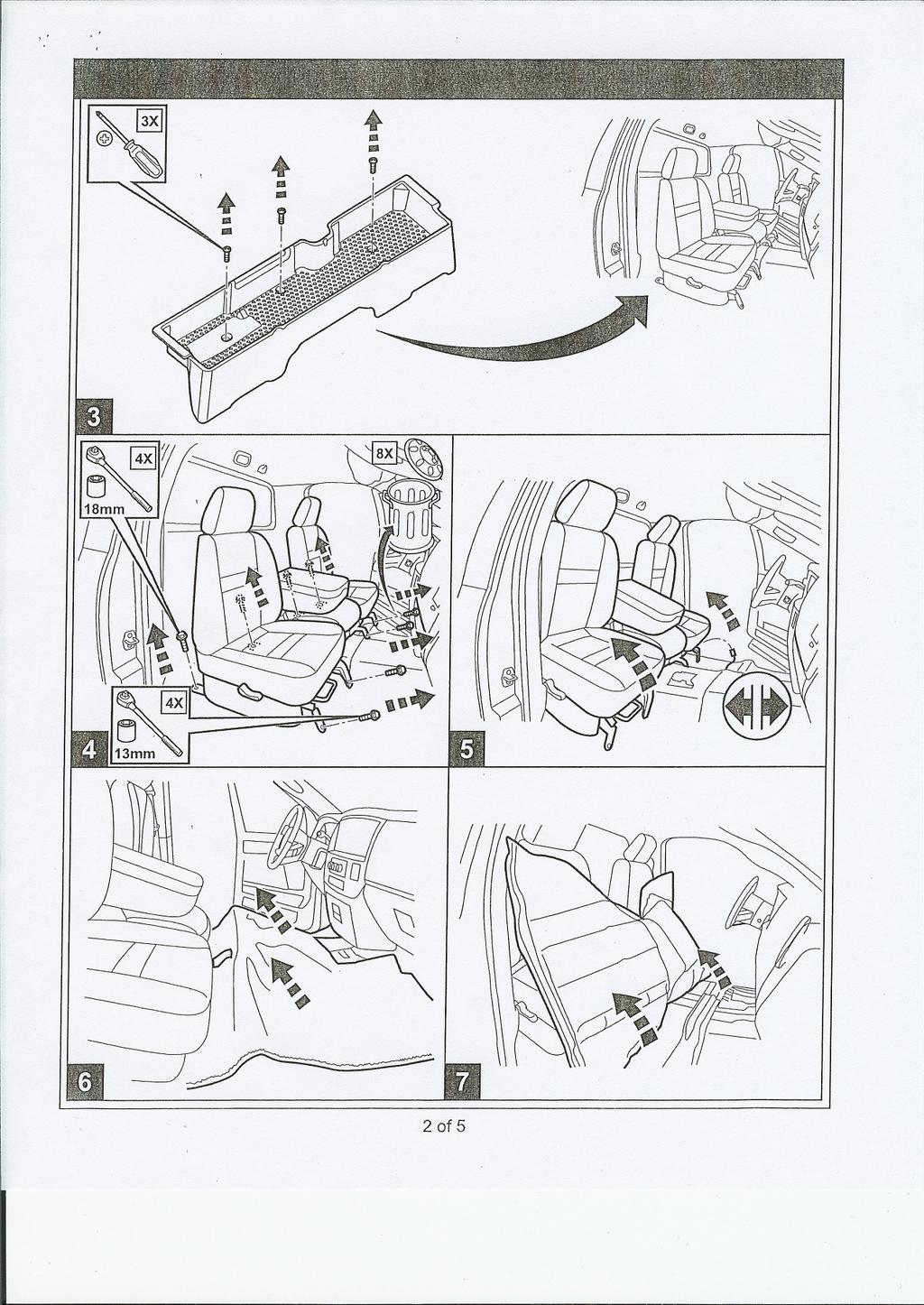
7 PTO Installation Alternative In addition to the current method of PTO installation from beneath the vehicle, an alternative method has been developed that allows the installation from above by removing the PTO patch panel in the floor. The instructions are as follows. 1. Remove the rear package tray located behind the seat from the vehicle. 2. Unbolt the seat and move it to the rear of the cabin where the package tray was removed. 3. Remove the sill guards (rocker panel covers) passenger side to allow the vinyl floor mat to be lifted. They are removed by prying straight up to disengage metal clips. 4. Lift the floor mat and fold it rearward and toward the drivers side to expose the patch panel


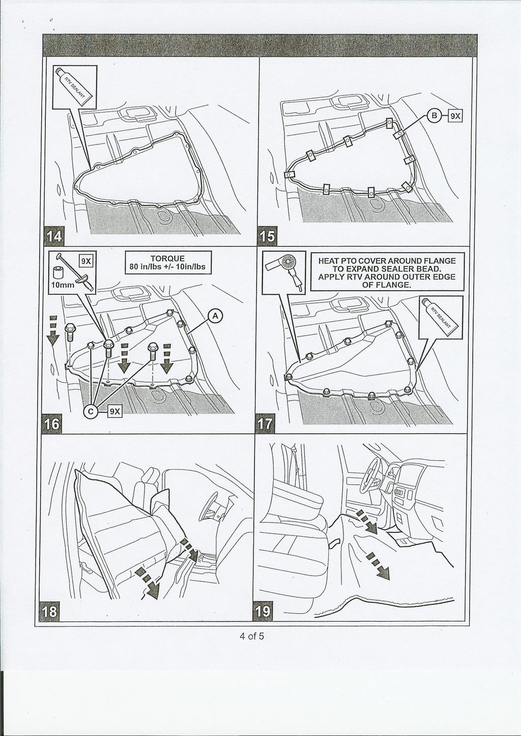
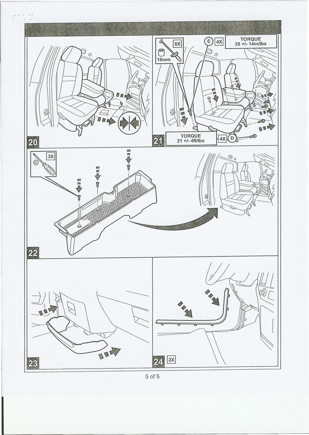
8 5. Remove the fasteners and sealer from around the patch panel. Cut away the sound deadener pad to expose the transmission PTO access. 6. You are now able to install and assemble the PTO and pump through the opening. Note: larger pumps must be inserted through the hole and moved toward the rear of the opening before installing the PTO. The pump is then slid forward to connect to the installed PTO. 7. To assemble, reverse the above procedure using RTV to reseal the PTO floor pan patch panel.
9 PTO Circuit Definition Chart The following chart is provided d to assist in correctly interfacing i the PTO with the vehicle: Circuit Name Type/Gauge/Color Circuit Functionality Description Usage K854F 18T - VT/BR - for T-DG- for 2008 remote throttle 5 volt supply 5 volt pwr supply to the remote potentiometer (remote's control power circuit). Supplied by the engine controller Remote throttle control K400E 18T - BR/VT remote throttle sensor return (gnd) K128 18T - DB/WT remote throttle signal K129 18T - DB/DG remote throttle switch K119 18T - LG/BK Maximum engine speed limit Remote's ground (ground to the potentiometer of remote). Supplied by the engine controller. Do not hook to other grounding location Remote signal sent to the engine controller. Signal from the remote's potentiometer. On/Off switch provided by customer to "turn on/off remote function. Remote switch closes to ground. Connect ground side of switch to pin #8 in this connector. Do not ground to vehicle. Feature selects a lower maximum engine speed when switch is "on". Switch closes to ground. Customer supplied switch.connect ground side of switch to pin #8 in this connector. Do not ground to vehicle. Remote throttle control Remote throttle control Remote throttle control Max operating speed switch K810 18T - VT/DG Accelerator interlock F425 18T - PK Remote PTO Swicth V937C 18T - VT/BR Cruise control switch return K425 18T - OR/BR - for T-PK/YL - for 2008 PTO switch Disable accelerator control of engine by closing an operator installed switch. This switch closes to ground. Connect ground side of switch to pin #8 in this connector. Do not ground to vehicle. Customer supplied switch Customer supplied remote PTO on/off switch. Switch closes to ground. Connect ground side of switch to pin #8 in this connector. Do not ground to vehicle. Remote PTO Electrical ground for switch circuits. Ground returns to the engine controller. Do not hook to other grounding location. All customer supplied PTO switches ground to this pin. Please make appropriate protected splice. Circuit switches to ground using operator installed switch. Connect ground side of switch to pin #8 in this connector. Do not ground to vehicle. Master ground for all added PTO switches. Do not apply any "dirty" grounds to this location. Stationary PTO
10 CHASSIS CAB UPFITTER KIT WIRING DETAIL
11 Location B Wiring
12
13
14 2009 Sterling Bullet PTO/Body Builder Interface Wiring Diagram TRANS CONTROLLER AUTOMATIC TRANS ONLY MANUAL TRANS ONLY UPFITTER JUMPER CONNECTOR UNDER THE INSTRUMENT PANEL LH SIDE 3 G425 18T VT/YL PTO INDICATOR 4 F922 16T PK/RD IGN RUN FEED 1 K425 16T PK/YL PTO ON/OFF SW 2 V937 18T VT/BR PTO SW RETURN A422 14T RD UPFITTER BAT TO 10A IN TIPM B+ DASH INLINE K427 18T OR/LG PTO ENGAGE G425 18T VT/YL PTO INDICATOR F922 16T PK/RD IGN RUN FEED PTO POWER RELAY 87A Z914 18T BK GROUND 7 UNTERMINATED AND HEATSHRUNK (LOCATED IN ENGINE COMPARTMENT BY MASTER CYLINDER) TOP VIEW OF PDC PTO POWER RELAY REPLACEMENT PART INFORMATION: RELAY (TYCO): P/N E Z912 20T BK F504 20T GY/PK A421 16T RD/WT IGN FEED 20A BAT FEED 25A BAT FEED 25A RELAY TERMINAL (MOLEX): P/N AND FUSE (LITTLEFUSE): P/N ZXOCR (20A) P/N ZXOCR (25A) DASH/ CHASSIS INLINE A423 14T PK A422 14T RD F922 16T PK/RD IGN BAT BAT 20A 25A 25A WIRE FUSE LINK NOTE: 14T IS SHOWN HERE AS THE CIRCUIT GAUGE TO BE USED IF THE CIRCUITS ARE PROTECTED BY EITHER A 25A MINI OR MAXI FUSE. THE TOTAL CIRCUIT RESISTANCE IS LESS THAN 20 Mohm AND THE CIRCUITS DO NOT HAVE A MINIMUM VOLTAGE DROP REQUIREMENT. CIRCUIT GAUGE MUST BE RE-EVALUATED IF THESE CONDITIONS CHANGE. PDC K119 18T LG/BK MAX OPERATING SPEED SW K129 18T DB/DG REMOTE THROTTLE SW Z993 18T BK 4 CLUTCH UPSTOP SWITCH T26 18T DG/OR CLUTCH UPSTOP INPUT 3 ENGINE CONTROLLER B15 K128 18T DB/WT REMOTE THROTTLE SIGNAL K400E 18T BR/VT PPS 2 RETURN K854F 18T DG PPS V+ SUPPLY K810 18T VT/DG ACC INTERLOCK SW F425 18T PK REMOTE PTO SW V937C 18T VT/BR SPD CNTL SW RETURN UNTERMINATED AND HEATSHRUNK (LOCATED UNDER VEHICLE LH SIDE NEAR TRANS BELL HOUSING) A423 14T PK UPFITTER BAT+ CONNECTION A422 14T RD UPFITTER BAT+ CONNECTION A426 14T VT PASS THRU TO CABIN UNTERMINATED AND HEATSHRUNK (LOCATED AT REAR OF LH FRAME RAIL)

15 6.7L Diesel Electric Air Shift with G56 Manual Transmission
16 6.7L Diesel PTO with G56 Manual Transmission Stationary Remote Preset Mode
17 6.7L Diesel PTO with G56 Manual Transmission Stationary and Mobile Mode

18 6.7L Diesel with Aisin Automatic Transmission in Cab Stationary and Mobile Mode


19 6.7L Diesel with Aisin Automatic Transmission Stationary Remote Mode
20 Location of the Pressure Plugs Right Side Veiw (Passenger side) Torque Converter Out (to Cooler) 5 C1 (Clutch No1) Pressure 2 B1 (Brake No1) Pressure 6 C2 (Clutch No2) Pressure 3 B2 (Brake No2) Pressure 7 C3 (Clutch No3) Pressure 4 L/U (Lock Up Clutch) Pressure Left Side Veiw (Driver side) Lubrication 9 Line (Main) Pressure 10 Torque Converter In (from Cooler) 2.5 φ Hole Detail (All) 45 1/2-20UNF-2B 15
21
22

23
24
25
2008 Chassis Cab PTO Operation & Installation Guide 05/06/2008
 05/06/2008 PTO Operation The 3500/4500/5500 Dodge Chassis Cab vehicle, when equipped with either the automatic Aisin 6spd or manual G56 6spd transmissions, will allow for an aftermarket upfit with a transmission
PTO General Guidelines
 PTO General Guidelines PTO PTO GENERAL General GUIDELES Guidelines The Dodge Ram 3500/4500/5500 Chassis cab models equipped with diesel engines that have the PTO prep option (LBN) have the capability of
PTO General Guidelines
 PTO General Guidelines PTO GENERAL GUIDELES The Ram 3500/4500/5500 Chassis cab models equipped with diesel engines that have the PTO prep option (LBN) have the capability of mounting and controlling a
Pump sizes. PTO Limitations Chassis Cab PTO Operation & Installation Guide 12/19/2013
 PTO GENERAL GUIDELINES The Ram 3500/4500/5500 Chassis cab models equipped with gas and diesel engines that have the PTO prep option (LBN or LBV) have the capability of mounting and controlling a PTO. The
PTO GENERAL GUIDELINES
 PTO GENERAL GUIDELES The Ram 3500/4500/5500 Chassis cab models equipped with gas and diesel engines that have the PTO prep option (LBN or LBV) have the capability of mounting and controlling a PTO. The
Owner s Manual Power Take-Offs
 Power Take-Offs Effective: June 2013 Supersedes: HY25-1240-M1/US January 2013 230 Series 231 Series 236 Series 238 Series 270 Series 271 Series 800 Series 852 Series 885 Series WARNING User Responsibility
DATE: 7/29/99. PAGE: 1 of 32
 UI BULLETIN # 24 SUBJECT: Engine Speed Control for 7.4L (LP4/L21) Gas Engines MODELS AFFECTED: C-Series Trucks MODEL YEAR(S): 1999/2000 DATE: 7/29/99 PAGE: 1 of 32 The purpose of this bulletin is to provide
2007 W-SERIES (CHEVROLET & GMC) N-SERIES (ISUZU) 274
 N-SERIES (ISUZU) 274") 2007 W-SERIES (CHEVROLET & GMC) N-SERIES (ISUZU) 274 2005 PTO SECTION FOR THE 4HK1-TC ENGINE (IL5) System Operating Instructions PTO Power Take Off Option Electrical Requirements SECTION OUTLINE Overview
2007 W-SERIES (CHEVROLET & GMC) N-SERIES (ISUZU) 274 2005 PTO SECTION FOR THE 4HK1-TC ENGINE (IL5) System Operating Instructions PTO Power Take Off Option Electrical Requirements SECTION OUTLINE Overview
New Stationary Elevated Idle Control for 2005 Model Year Light Trucks
 SVE BULLETIN SPECIAL VEHICLE ENGINEERING BODY BUILDERS ADVISORY SERVICE Toll-free: (877) 840-4338 E-Mail: bbasqa@ford.com (preferred) Fax: (313) 594-2633 Website: www.fleet.ford.com/truckbbas Q-108 Date:
Revision Update Revision Date
 Q-173R4 SVE BULLETIN SPECIAL VEHICLE ENGINEERING BODY BUILDERS ADVISORY SERVICE E-Mail via website: www.fleet.ford.com/truckbbas (click "Contact Us") Toll-free: (877) 840-4338 QVM Bulletin: Q-173R4 Date:
MaxxForce 11 and 13 (2010)
") MaxxForce 11 and 13 (2010) Overview: In Cab Control NAV_PTOIC_070511 In-Cab Control TABLE OF CONTENTS General Overview: In-Cab Control... 1 Description and Operation... 1 OPERATION...1 STATIONARY VARIABLE...1
MaxxForce 11 and 13 (2010) Overview: In Cab Control NAV_PTOIC_070511 In-Cab Control TABLE OF CONTENTS General Overview: In-Cab Control... 1 Description and Operation... 1 OPERATION...1 STATIONARY VARIABLE...1
International A26 (2017)
") International A26 (2017) Overview: Control - In Cab A26_ICESC_12292017 In-Cab Control TABLE OF CONTENTS General Overview: In-Cab Control... 1 Description and Operation... 1 OPERATION...1 STATIONARY VARIABLE...1
International A26 (2017) Overview: Control - In Cab A26_ICESC_12292017 In-Cab Control TABLE OF CONTENTS General Overview: In-Cab Control... 1 Description and Operation... 1 OPERATION...1 STATIONARY VARIABLE...1
QVM Bulletin: Q-180R4 Date: 26 April, Revision Update Revision Date and later F-Super Duty 6.7L Engine Stationary Elevated Idle Control
 Q-180R4 SVE BULLETIN SPECIAL VEHICLE ENGINEERING BODY BUILDERS ADVISORY SERVICE E-Mail via website: www.fleet.ford.com/truckbbas (click "Contact Us") Toll-free: (877) 840-4338 QVM Bulletin: Q-180R4 Date:
Subject: Power Take Off (PTO) Models Affected: ADVISORY:
 Models Affected: ADVISORY:") Subject: Power Take Off (PTO) Subsystem Operating Description and Application Guide Models Affected: All New C/K 3500HD CC Chevrolet Silverado / GMC Sierra. Models C/K 36003, 36403 & 36043 Model Years:
Subject: Power Take Off (PTO) Subsystem Operating Description and Application Guide Models Affected: All New C/K 3500HD CC Chevrolet Silverado / GMC Sierra. Models C/K 36003, 36403 & 36043 Model Years:
Torque Convertor Control System
 22 September 2015 PN#1030395 TorqLoc (I-00208) 1 BD TorqLoc Torque Convertor Control System Part# 1030395 Installation Manual for the following applications: BD Brakes for Dodge, Ford and Chevrolet Pac
Cruise Control Diagnosis
 1999 Pontiac Firebird Cruise Control Diagnosis Circuit Description The Cruise Control system is a speed control system that maintains a desired vehicle speed under normal driving conditions. The cruise
SVE BULLETIN and later Transit Stationary Elevated Idle Control
 Q-239 2016 and later Transit Stationary Elevated Idle Control Models Affected All 2016 and later Model Year Transit Vans, Wagons, Cutaways, and Chassis Cab Vehicles. Purpose To explain changes and functions
2008 Frequently Asked Questions BACK
 1. Where can I pick up the RPM or Vehicle Speed signal? The Dodge vehicles utilize CAN BUS type communication and therefore do not have traditional hard wiring for these signals. At this time Dodge does
SVE BULLETIN. QVM Bulletin: Q-248R1 Date: 16 June, 2016
 Q-248R1 SVE BULLETIN SPECIAL VEHICLE ENGINEERING BODY BUILDERS ADVISORY SERVICE E-Mail via website: www.fleet.ford.com/truckbbas (click "Contact Us") Toll-free: (877) 840-4338 QVM Bulletin: Q-248R1 Date:
MODEL YEAR(S): 2005 DATE: 09/08/2005 REVISION DATE: PAGE: 1 of 41 ADVISORY
: 2005 DATE: 09/08/2005 REVISION DATE: PAGE: 1 of 41 ADVISORY") UI BULLETIN # 74 SUBJECT: PTO Procedure for Tilt Cab Trucks with (7.8L) LG4 Engine MODELS AFFECTED: T-Series Medium Duty Truck (F6/F7/F8) (Chevrolet, GMC & Isuzu) MODEL YEAR(S): 2005 DATE: 09/08/2005 REVISION
UI BULLETIN # 74 SUBJECT: PTO Procedure for Tilt Cab Trucks with (7.8L) LG4 Engine MODELS AFFECTED: T-Series Medium Duty Truck (F6/F7/F8) (Chevrolet, GMC & Isuzu) MODEL YEAR(S): 2005 DATE: 09/08/2005 REVISION
Torque Convertor Control System
 1 BD AutoLoc Torque Convertor Control System Part# 1030390 Installation Manual for the following applications: BD Brakes for Dodge, Ford and Chevrolet Pac Brake for Dodge & Ford Jacobs E-Brake for 1994-98
Optimized Idle Aftermarket Installation Kits On-Highway Truck Applications (P/N: )
") 18SP655 Optimized Idle Aftermarket Installation Kits On-Highway Truck Applications (P/N: 23538534) KIT DESCRIPTION The Optimized Idle Aftermarket Installation Kit provides the components necessary for
18SP655 Optimized Idle Aftermarket Installation Kits On-Highway Truck Applications (P/N: 23538534) KIT DESCRIPTION The Optimized Idle Aftermarket Installation Kit provides the components necessary for
Power Take-Off (PTO) Description and Operation
 Description and Operation") Page 1 of 5 2007 Chevrolet Kodiak C-Series (Conventional) C4/C5 Kodiak, TopKick C-Series Service Manual Transmission/Transaxle Power Take-Off Description and Operation Document ID: 2033971 Power Take-Off
Page 1 of 5 2007 Chevrolet Kodiak C-Series (Conventional) C4/C5 Kodiak, TopKick C-Series Service Manual Transmission/Transaxle Power Take-Off Description and Operation Document ID: 2033971 Power Take-Off
NISSAN TRUCKS ELECTRONIC CRUISE CONTROL KIT AUTOMATIC & MANUAL TRANSMISSIONS PART NUMBER:
 General Applicability This cruise control was tested and verified on: 2008-2011 Nissan Frontier 2008-2011 Nissan Titan This cruise control may not function correctly on unverified vehicles. See www.rostra.com
MaxxForce 7 (2010) PTO Remote Engine Speed Control Navistar, Inc.
 PTO Remote Engine Speed Control Navistar, Inc.") MaxxForce 7 (2010) Overview: Remote Engine Speed Control NAV_R _041111 TABLE OF CONTENTS General Overview: Remote Engine Speed Control... 1 Description and Operation... 1 OPERATION...1 FEATURE INTERACTION...2
MaxxForce 7 (2010) Overview: Remote Engine Speed Control NAV_R _041111 TABLE OF CONTENTS General Overview: Remote Engine Speed Control... 1 Description and Operation... 1 OPERATION...1 FEATURE INTERACTION...2
Pressing and holding the + RES switch, when the Cruise Control System is engaged, will allow the vehicle to
 CRUISE CONTROL DESCRIPTION AN... CRUISE CONTROL DESCRIPTION AND OPERATION (CRUISE CONTROL) Document ID# 2088041 Cruise Control Description and Operation Cruise control is a speed control system that maintains
DIAMOND LOGIC CONTROL SYSTEMS ENGINE SPEED CONTROL FEATURES
 INTRODUCTION Section 1 International Truck Electrical System Overview This section gives an overview of the electrical system. Section 2 Electronic Service Tool Use and Feature Programming The Electronic
October 11, 2018 ADVISORY:
 Subject: Models Years Affected: 2015 thru 2019 Models Affected: Origination Date: Revision Date: Power Take Off (PTO) Subsystem Operating Description and Application Guide C/K 3500HD CC Chevrolet Silverado
Aftermarket Interface Module
 An ISO 9001:2008 Registered Company Aftermarket Interface Module (2015-2018 Ford Transit) AIM514-B High Side Solenoid type Coolant Valve Control AIM515-B Motor Reversing type Coolant Valve Control Introduction
GTWY505 Fast Idle, Shift Interlock, I/O Ford E-Series
 An ISO 9001:2008 Registered Company GTWY505 Fast Idle, Shift Interlock, I/O 2009-2018 Ford E-Series Introduction The Gateway 505 is a wheelchair lift safety interlock which will only work with the ignition
MaxxForce DT, 9, 10 (2010)
") MaxxForce DT, 9, 10 (2010) Overview: Remote Speed Control NAV_R _030411 TABLE OF CONTENTS General Overview: Remote Speed Control... 1 Description and Operation... 1 OPERATION...1 FEATURE INTERACTION...2
MaxxForce DT, 9, 10 (2010) Overview: Remote Speed Control NAV_R _030411 TABLE OF CONTENTS General Overview: Remote Speed Control... 1 Description and Operation... 1 OPERATION...1 FEATURE INTERACTION...2
ATS Diesel Performance INST. Installation Manual for 2003 Dodge Cummins Version 3.1
 Installation Manual for 2003 Dodge Cummins Version 3.1 Please read all instructions before the installation of the ATS Co-Pilot Module Thank you for purchasing the ATS Co-Pilot Module Torque converter/exhaust
SVE BULLETIN. QVM Bulletin: Q-236R4 Date: 12 August, 2015
 Q-236R4 SVE BULLETIN SPECIAL VEHICLE ENGINEERING BODY BUILDERS ADVISORY SERVICE E-Mail via website: www.fleet.ford.com/truckbbas (click "Contact Us") Toll-free: (877) 840-4338 QVM Bulletin: Q-236R4 Date:
2010 FORD TRANSIT ELECTRONIC CRUISE KIT Part Number:
 General Applicability Recommended Tools Item # Qty. Description 1. 250-2758 1 Cruise Control Module 2. 250-2760 1 Switch Harness 3. 250-2759 1 Main Wiring Harness 4. 250-2771 1 Pedal Interface Harness
Installation Manual v3.0: Dodge Cummins. Please read all instructions before the installation of the ATS Co-Pilot
 Installation Manual v3.0: 2004-2005 Dodge Cummins Please read all instructions before the installation of the ATS Co-Pilot Thank you for purchasing the ATS Co-Pilot Torque converter/exhaust brake controller.
Engine Function Module (EFM) Manual
 Manual") MY 2011 - Present (Manual # 99905297) Engine Function Module (EFM) Manual Model Year 2011 - Present Revised 20140609 IOWA MOLD TOOLING CO., INC. PO Box 189 Garner, IA 50438 Tel: 641-923-3711 FAX: 641-923-2424
MY 2011 - Present (Manual # 99905297) Engine Function Module (EFM) Manual Model Year 2011 - Present Revised 20140609 IOWA MOLD TOOLING CO., INC. PO Box 189 Garner, IA 50438 Tel: 641-923-3711 FAX: 641-923-2424
Installing the Throttle Commander Ford F250 F550 Super Duty
 Installing the Throttle Commander Ford F250 F550 Super Duty 7.3L Power Stroke Diesel 1996 up to 2001.25 T500011 and T500028 1.0 Preparing for Installation...5 2.0 Installing the Throttle Controller...5
GTWY605 Fast Idle, Shift Interlock, I/O Chevy 610 Van - 6.0L and 6.6L Engines Contact InterMotive for additional vehicle applications.
 An ISO 9001:2008 Registered Company GTWY605 Fast Idle, Shift Interlock, I/O 2009-2017 Chevy 610 Van - 6.0L and 6.6L Engines Contact InterMotive for additional vehicle applications. Introduction The Gateway
C FORD F250 / F L POWERSTROKE DIESEL WITH AUTOMATIC TRANSMISSIONS ONLY
 EXHAUST BRAKES C40019 1999-2003 FORD F250 / F350 7.3L POWERSTROKE DIESEL WITH AUTOMATIC TRANSMISSIONS ONLY Getting Started Thank you and congratulations on your purchase of a Pacbrake exhaust retarder.
GM PTO. Systems; Part 2 of 2
 GM PTO Systems; Part 2 of 2 GM PTO Systems; Part 2 of 2 by Steve Garrett www.atra.com Welcome back. In this segment we will look a little deeper into the GM Power Takeoff (PTO) system. GM PTO systems consist
Installing the Throttle Commander
 Installing the Throttle Commander Ford 6.0L Diesel Powerstroke 2005-2007 F250-550 Super Duty 2005-2010 E250-550 Econoline (8500+ GVW) Ford 6.4L Diesel Powerstroke 2008-2010 F250-550 Super Duty T500107
HL515-B Fast Idle, Lift Interlock Ford Transit
 An ISO 9001:2008 Registered Company HL515-B Fast Idle, Lift Interlock 2015-2018 Ford Transit Introduction The HighLock 515-B is a wheelchair lift safety interlock which will only work with the ignition
1999 Toyota RAV ACCESSORIES & EQUIPMENT Cruise Control Systems - RAV4
 1999 ACCESSORIES & EQUIPMENT Cruise Control Systems - RAV4 DESCRIPTION WARNING: Deactivate air bag system before performing any service operation. See AIR BAG RESTRAINT SYSTEMS article. DO NOT apply electrical
1. Cruise Control CRUISE CONTROL A: OPERATION B: LOCATION OF COMPONENTS. CC(STi)-2
-2") W1860BE.book Page 2 Tuesday, January 28, 2003 11:01 PM 1. Cruise Control A: OPERATION The cruise control system automatically controls the vehicle speed. It allows the vehicle to run at a constant speed
W1860BE.book Page 2 Tuesday, January 28, 2003 11:01 PM 1. Cruise Control A: OPERATION The cruise control system automatically controls the vehicle speed. It allows the vehicle to run at a constant speed
MaxxForce DT, 9, 10 ( )
") MaxxForce DT, 9, 10 (2007-2009) Overview: TABLE OF CONTENTS General Overview:... 1 Description and Operation... 1 OPERATION...1 Programmable Parameters... 2 Parameter Setup... 2 Frequently Asked Questions...
MaxxForce DT, 9, 10 (2007-2009) Overview: TABLE OF CONTENTS General Overview:... 1 Description and Operation... 1 OPERATION...1 Programmable Parameters... 2 Parameter Setup... 2 Frequently Asked Questions...
An ISO 9001:2015 Registered Company
 Introduction An ISO 9001:2015 Registered Company HL550-B Fast Idle, Lift Interlock 2011-2016 Ford F250-F550 2017-2019 Ford F250-F550 (B-HL550*) 2016-2017 Ford F650/750** *Uses the Ford 24-Pin Data Link
AFIS515VSX-B Fast Idle System Ford Transit 2015 American General MV-1 3.7L Engine
 An ISO 9001:2008 Registered Company AFIS515VSX-B Fast Idle System 2015-2018 Ford Transit 2015 American General MV-1 3.7L Engine Introduction The AFIS515VSX-B is a Fast Idle system that elevates engine
200C II BRAKE SYSTEM
 200C II BRAKE SYSTEM The braking system on the 200C II Kress Coal Hauler uses hydraulic oil pressure from both the System and Steering accumulator circuits. Using oil from both circuits provides braking
MaxxForce DT, 9, 10 ( )
") MaxxForce DT, 9, 10 (2007-2009) Overview: Idle Shutdown Timer (Non-CARB Certified Engines) NAV_IST_030711 Idle Shut Down Timer TABLE OF CONTENTS General Overview: Idle Shutdown Timer... 1 Description and
MaxxForce DT, 9, 10 (2007-2009) Overview: Idle Shutdown Timer (Non-CARB Certified Engines) NAV_IST_030711 Idle Shut Down Timer TABLE OF CONTENTS General Overview: Idle Shutdown Timer... 1 Description and
GTWY515, GTWY516* Fast Idle, Shift Interlock, I/O Ford Transit Introduction
 An ISO 9001:2015 Registered Company GTWY515, GTWY516* Fast Idle, Shift Interlock, I/O 2015-2019 Ford Transit Introduction The Gateway 515 and 516 are wheelchair lift safety interlocks which allows lift
CRUISE CONTROL SYSTEM
 CRUISE CONTROL SYSTEM 1994 Toyota Celica 1994 ACCESSORIES & EQUIPMENT Toyota Motor Sales, U.S.A., Inc. - Cruise Control Systems Celica DESCRIPTION Cruise control system consists of Cruise Control Electronic
An ISO 9001:2008 Registered Company
 Overview An ISO 9001:2008 Registered Company AFIS422VSX-B Advanced Fast Idle System - Transit Application 2009-2017 Ford E-Series, all engines 2009-2010 Ford F-250 - F-550, all engines 2014-2018 Ford F53/F59,
An ISO 9001:2008 Registered Company
 Introduction An ISO 9001:2008 Registered Company GTWY506 Fast Idle, Shift Interlock, I/O 2011-2016 Ford F250-F550 2017 Ford F250-F550 (Uses the Ford 24-Pin Data Link Harness) 2016-2017 Ford F650/750* *Transmission
QGP Allegro Bus (Tiffin's ECM Template)
") ISL9 EPA 2010 CM2250 Accelerator Interlock Accelerator Options Dual Accelerator Remote Accelerator Pedal or Lever Adjustable Low Air Speed Low Idle Speed Low Idle Speed Adjustment Switch Aftertreatment
ISL9 EPA 2010 CM2250 Accelerator Interlock Accelerator Options Dual Accelerator Remote Accelerator Pedal or Lever Adjustable Low Air Speed Low Idle Speed Low Idle Speed Adjustment Switch Aftertreatment
SCHEMATIC AND ROUTING DIAGRAMS
 2004 ACCESSORIES & EQUIPMENT Cruise Control - Corvette SCHEMATIC AND ROUTING DIAGRAMS CRUISE CONTROL SCHEMATICS Fig. 1: Cruise Control Switch, Throttle Actuator Control Motor And Cruise Control Release
2001 Honda Civic EX ACCESSORIES & EQUIPMENT' 'Cruise Control Systems - Civic & CR-V 2001 ACCESSORIES & EQUIPMENT
 DESCRIPTION 2001 ACCESSORIES & EQUIPMENT Cruise Control Systems - Civic & CR-V Cruise control system uses mechanical and electrically operated devices to maintain vehicle speed settings greater than 25
GM6B SERIES PTO INSTALLATION FOR GENERAL MOTORS 3600 CAB CHASSIS WITH ALLISON 1000 SERIES AUTOMATIC TRANSMISSION
 KEEP IN VEHICLE READ OPERATING INSTRUCTIONS INSIDE BEFORE OPERATING PTO GM6B SERIES PTO INSTALLATION FOR GENERAL MOTORS 3600 CAB CHASSIS WITH ALLISON 1000 SERIES AUTOMATIC TRANSMISSION Use this manual
Ford Super Duty F-250, F and up
 Ford Super Duty F-250, F-350 2005 and up Installing Upfitter Switches by Richard L. Ray If you want to add a few aftermarket options to your new Ford Super Duty, Ford Motor Company makes things easy for
CRUISE CONTROL SYSTEM
 CRUISE CONTROL 1. Cruise Control A: OPERATION The cruise control system automatically controls the vehicle speed. It allows the vehicle to run at a constant speed without need for the driver to keep the
MaxxForce 15 (2011) Overview: Idle Shutdown Timer (including Certified Clean Idle) 2011 Navistar, Inc.
 Overview: Idle Shutdown Timer (including Certified Clean Idle) 2011 Navistar, Inc.") MaxxForce 15 (2011) Overview: (including Certified Clean Idle) NAV_IST_070111 Idle Shut Down Timer TABLE OF CONTENTS General Overview:... 1 Description and Operation...1 OPERATION STANDARD IST... 2 OPERATION
MaxxForce 15 (2011) Overview: (including Certified Clean Idle) NAV_IST_070111 Idle Shut Down Timer TABLE OF CONTENTS General Overview:... 1 Description and Operation...1 OPERATION STANDARD IST... 2 OPERATION
Installing the Throttle Commander Ford F250 F550 Super Duty
 Installing the Throttle Commander Ford F250 F550 Super Duty 6.0 L Power Stroke Diesel 2003.25 2004 T500082, T500083 and T500084 1.0 Preparing for Installation...5 2.0 Installing the Throttle Control Box...5
AP500 FAULT FINDING NEW INSTALLATION
 AP500 FAULT FINDING NEW INSTALLATION This Bulletin covers the AP500 model which is identified by a black plastic Electronic Module with a silver printed label. This module would normally be mounted behind
DirectMount EXHAUST BRAKES
 DirectMount EXHAUST BRAKES APPLICATION: Fixed Orifice and PRXB Exhaust Brakes 2003 2005 Dodge Trucks with 3.5" & 4" Exhaust and 47RE & 48RE Automatic Transmissions Only Vehicles with an existing air compressor
CRUISE CONTROL SYSTEM
 CRUISE CONTROL SYSTEM 1992 Infiniti G20 1991-92 SAFETY EQUIPMENT Infiniti Cruise Control Systems G20, M30, Q45 DESCRIPTION & OPERATION NOTE: For system component locations, see SYSTEM COMPONENT LOCATIONS.
Electrical Systems - Machine Electrical System. Electrical System Components Diagram Electrical System Components
 Section 5.1 Electrical Systems - Machine Electrical System Electrical System Components Diagram... 5.1.2 Electrical System Components.... 5.1.3 Engine Electrical Load Center: Engine Electrical Load Center
CUMMINS FAULT CODE: 1239 PID: SPN: 2623 FMI: 3/3 LAMP: AMBER
 CUMMINS ACCELERATOR PEDAL OR LEVER POSITION SENSOR 2 CIRCUIT - VOLTAGE ABOVE NORMAL OR HORTED TO HIGH SOURCE FAULT CODE: 1239 PID: SPN: 2623 FMI: 3/3 LAMP: AMBER DESCRIPTION ISX and ISM Accelerator Pedal
CRUISE CONTROL SYSTEM
 CRUISE CONTROL SYSTEM 1994 Volvo 960 1994 ACCESSORIES/SAFETY EQUIPMENT Cruise Control System 960 DESCRIPTION & OPERATION MAIN SWITCH Cruise control main switch is located at end of directional signal lever.
MaxxForce 11 and 13 ( )
") MaxxForce 11 and 13 (2007-2009) Overview: TABLE OF CONTENTS General Overview:... 1 Description and Operation... 1 OPERATION...1 Programmable Parameters... 2 Parameter Setup... 3 Frequently Asked Questions...
MaxxForce 11 and 13 (2007-2009) Overview: TABLE OF CONTENTS General Overview:... 1 Description and Operation... 1 OPERATION...1 Programmable Parameters... 2 Parameter Setup... 3 Frequently Asked Questions...
On all settings above 100 horsepower the following precautions should be observed:
 ELECTRONIC FUEL INJECTED 5.0 COYOTE PLATE SYSTEM INSTALLATION INSTRUCTIONS Congratulations on the purchase of your Nitrous Express Coyote Plate system. Nitrous Express utilizes only the highest quality
HL610-B Fast Idle, Lift Interlock Chevy 610 Van 6.0L and 6.6L Contact InterMotive for additional vehicle applications
 An ISO 9001:2015 Registered Company HL610-B Fast Idle, Lift Interlock 2009-2019 Chevy 610 Van 6.0L and 6.6L Contact InterMotive for additional vehicle applications Introduction The HighLock 610 is a wheelchair
MINOTOUR SERVICE MANUAL
 MINOTOUR SERVICE MANUAL The following areas are covered in this manual: Interlock Feature Vandalock Feature AC System Heaters Passenger Advisory System MINOTOUR SERVICE MANUAL ELECTRICAL TROUBLESHOOTING
CRUISE CONTROL SYSTEM
 CRUISE CONTROL SYSTEM CONTROL SYSTEM PARTS LOCATION CRUISE CONTROL CRUISE CONTROL SYSTEM 1 ENGINE ROOM R/B AND J/B MAIN BODY ECU (INSTRUMENT PANEL J/B) B142328E05 2 CRUISE CONTROL CRUISE CONTROL SYSTEM
G - TESTS W/CODES - 2.2L
 G - TESTS W/CODES - 2.2L 1994 Toyota Celica 1994 ENGINE PERFORMANCE Toyota 2.2L Self-Diagnostics Celica INTRODUCTION If no faults were found while performing F - BASIC TESTING, proceed with self-diagnostics.
Installation Manual for VMAC Throttle Commander Throttle Control T500111
 Installation Manual for VMAC Throttle Commander Throttle Control T500111 2006-2007 Classic GMC CK2500-3500 6.0L Gasoline Engines 1.0 Preparation for Installation...4 1.1 Automatic Transmission Trucks...4
CRUISE CONTROL SPEED LIMITER Rev. 4.0
 INSTALLATION f MANUAL CRUISE CONTROL & SPEED LIMITER AP900Series SL900Series 231.0004530 Rev. 4.0 1 2 CONTENTS: Chapters 1 Kit contents. 3 2 Tools required 4 3 Electronics module location... 5 4 Input
CRUISE CONTROL SYSTEM
 CRUISE CONTROL CRUISE CONTROL SYSTEM CRUISE CONTROL SYSTEM PRECAUTION 1 1. HANDLING PRECAUTION FOR CRUISE CONTROL SYSTEM (a) Turn the cruise control main switch OFF when not using the cruise control system.
Quick Setup Guide for IntelliAg Model YP40 20 Air Pro
 STEP 1: Pre-Programming Preparation: The Quick Guide assumes the Virtual Terminal, Master Switch, Working Set Master, Working Set Member, and all sensors have been connected and properly installed. Reference
PRXB EXHAUST BRAKE MAXIMUM EXHAUST FLOW DESIGN
 MAXIMUM EXHAUST FLOW DESIGN PRXB EXHAUST BRAKE C44072/C44073/C44074/C44075/C44076 APPLICATION: 994-2002 DODGE RAM TRUCKS W/5.9L CUMMINS DIESEL ENGINES WITH MANUAL & AUTOMATIC TRANSMISSIONS STOCK DODGE
CRUISE CONTROL WITH ELECTRIC ACTUATOR. Group 61 - Chassis Electrics
 CRUISE CONTROL WITH ELECTRIC ACTUATOR Group 61 - Chassis Electrics Produced By: BMW of North America, Inc Issued 7/83 61-09 CRUISE CONTROL WITH ELECTRIC ACTUATOR The electric actuator type cruise control
Parameters (VIN:1FUJGLDR0BLAY1556, ESN:472903S )
") Page 1 of 6 CPC02T PGR002 Vehicle Parameters I Transmission Type PGR003 Common Limiters Adjusted Idle Configuration Eng Speed Limit While Veh Stop Max Adjusted Idle Speed Max Engine Speed Max Road Speed
Page 1 of 6 CPC02T PGR002 Vehicle Parameters I Transmission Type PGR003 Common Limiters Adjusted Idle Configuration Eng Speed Limit While Veh Stop Max Adjusted Idle Speed Max Engine Speed Max Road Speed
Activation of a split shaft power take-off. Function
 Function Function The function is intended to activate the power take-off from the driver area and from outside the cab. The power take-off is controlled by the BCI control unit. For the control of the
2002 F-150 Workshop Manual
 Page 1 of 23 SECTION 310-03: Speed Control 2002 F-150 Workshop Manual DIAGNOSIS AND TESTING Procedure revision date: 08/07/2006 Speed Control Refer to Wiring Diagrams Cell 31, Speed Control for schematic
Versaguard MAX Console OEM Guide
 Versaguard MAX Console OEM Guide TABLE OF CONTENTS SECTION PAGE 1 FUNCTION OVERVIEW 1.1 LCD INFMATION CENTER... 1 1.2 LCD QUICK BUTTONS... 2 1.3 LED INDICATS... 2 1.4 ELECTRONIC PARKING BRAKE... 2 1.5
PRXB EXHAUST BRAKE HIGH PERFORMANCE
 HIGH PERFORMANCE PRXB EXHAUST BRAKE C44059, C4406, C44063, C44065 APPLICATION 994-2002 DODGE RAM AUTOMATIC TRUCKS EQUIPPED WITH 47RE TRANSMISSIONS WITH 5.9L, 24 VALVE CUMMINS DIESEL ENGINES GETTING STARTED
Installation Manual for Dodge 12V Cummins Version 3.7. Please read all instructions before the installation of the ATS Co-Pilot
 Installation Manual for 1994-1998 Dodge 12V Cummins Version 3.7 Please read all instructions before the installation of the ATS Co-Pilot Thank you for purchasing the ATS Co-Pilot. This manual is to assist
CRUISE CONTROL SYSTEM
 Negative (-) Battery Terminal CRUISE CONTROL CRUISE CONTROL SYSTEM Cable System name METER / GAUGE SYSTEM D033496E01 CRUISE CONTROL SYSTEM PRECAUTION 1 1. DISCONNECT AND RECONNECT CABLE OF NEGATIVE BATTERY
CPC02T. PGR002 Vehicle Parameters I. PGR003 Common Limiters. PGR005 Limiters LIM0 and LIM1. PGR006 Limiters AC and LIM2
 Page 1 of 6 CPC02T PGR002 Vehicle Parameters I Drive Off Function drive off function Transmission Type Manual, without Neutral Switch PGR003 Common Limiters Adjusted Idle Configuration enabled if neutral
Allison Lockup Controller
 19 February 2018 1031311/1031312/1031313 Allison Transmission Lockup and Pressure Module (I-00413) 1 Allison Lockup Controller Transmission Lockup and Pressure Controller 1031311 1031312 1031313 2001-2010
SALDET SALES & SERVICE, INC. CLINTON TOWNSHIP, MICHIGAN
 Form 1254 BRAKETRON Electronic Motor Brake Instructions SALDET SALES & SERVICE, INC. CLINTON TOWNSHIP, MICHIGAN TABLE OF CONTENTS SECTION TITLE PAGE I. Introduction 1 II. Specifications 1 III. Principles
Body Builders Layout Book
 1 INDEX Application Information Page 2-5 Engine PCM Pins E-250/350/450 6 F-250/350/450/550 7 Battery Voltage Sources (VPWR) & Customer Access Signals E-250/350/450 F-250/350/450/550 8 9 Access & Pass-Thru
HINO PTO INTERFACE PTO INSTALLATION AND OPERATOR S MANUAL KEEP IN VEHICLE. FOR Allison 2500 With CS6B-A67**-S3*H PTO
 KEEP IN VEHICLE READ OPERATING INSTRUCTIONS INSIDE BEFORE OPERATING PTO HINO PTO INTERFACE PTO INSTALLATION AND OPERATOR S MANUAL FOR Allison 2500 With CS6B-A67**-S3*H PTO Muncie Power Products, Inc. Important
CRUISE CONTROL SYSTEM
 CRUISE CONTROL CRUISE CONTROL SYSTEM CRUISE CONTROL SYSTEM PRECAUTION 1 1. NOTICE FOR INITIALIZATION NOTICE: When the cable of the negative () battery terminal is disconnected, initialize the following
AutoControl Pressure Governor
 AutoControl Governor OPERATION and INSTALLATION MANUAL MODEL WSD-100: Cummins Electronics Engines-ISB, ISC, ISL, ISM WSD-200: DDEC electronics engines-series 50 and Series 60 WSD-240: DDEC Series 40 engines
Dodge Cummins Positive Air Shutoff
 10 June 2013 1998-2002 24V 5.9 Dodge Cummins Positive Air Shutoff 1 1998.5-2002 5.9 Dodge Cummins Positive Air Shutoff P/N# 1036719 P/N# 1036719-M UPLEASE READ ALL INSTRUCTIONS BEFORE INSTALLATION 10 June
Installation Manual for Dodge 24V Cummins Version 3.1. Please read all instructions before the installation of the ATS Co-Pilot
 10/1/12 601-900-2218-INST Installation Manual for 1998.5-2002 Dodge 24V Cummins Version 3.1 Please read all instructions before the installation of the ATS Co-Pilot Thank you for purchasing the ATS Co-Pilot
International A26 (2017)
") International A26 (2017) Overview: TABLE OF CONTENTS General Overview:... 1 Description and Operation... 1 OPERATION...1 Parameter Setup... 2 Programmable Parameters... 4 Frequently Asked Questions...
International A26 (2017) Overview: TABLE OF CONTENTS General Overview:... 1 Description and Operation... 1 OPERATION...1 Parameter Setup... 2 Programmable Parameters... 4 Frequently Asked Questions...
Engine Function Module
 EFM MODULE: 99903412: 20110829 PAGE - 1 Engine Function Module MODEL YEAR 1998-2010 IOWA MOLD TOOLING CO., INC. BOX 189, GARNER, IA 50438-0189 TEL: 641-923-3711 MANUAL PART NUMBER 99903412 Iowa Mold Tooling
Quick Setup Guide for IntelliAg Model YP Air Pro
 STEP 1: Pre-Programming Preparation: The Quick Guide assumes the Virtual Terminal, Master Switch, Working Set Master, Working Set Member, and all sensors have been connected and properly installed. Reference
Dodge Cummins Positive Air Shutoff
 1998-2002 24V 5.9 Dodge Cummins Positive Air Shutoff (I-00181) 1 INSTALL MANUAL 1998.5-2002 5.9 Dodge Cummins Positive Air Shutoff P/N# 1036719 P/N# 1036719-M UPLEASE READ ALL INSTRUCTIONS BEFORE INSTALLATION
CSI-400 Installation Instructions
 CSI-400 Installation Instructions Kit Contents Installation Precautions: Roll down window to avoid locking keys in vehicle during installation Avoid mounting components or routing wires near hot surfaces