AUTOMATED SUB SANDWICH FOLDING MACHINE FINAL REPORT
|
|
|
- Prudence Johnson
- 6 years ago
- Views:
Transcription

1 EML 4905 Senior Design Project Spring 2017 A B.S. THESIS PREPARED IN PARTIAL FULFILLMENT OF THE REQUIREMENT FOR THE DEGREE OF BACHELOR OF SCIENCE IN MECHANICAL ENGINEERING AUTOMATED SUB SANDWICH FOLDING MACHINE FINAL REPORT Mena Abd El Malak Nelvin J. Chery Hani Kazemzadeh Berry Lamy Faculty Advisor: Dr. Sabri Tosunoglu April 20th, 2017 This B.S. thesis is written in partial fulfillment of the requirements in EML The contents represent the opinion of the authors and not the Department of Mechanical and Materials Engineering.
2 Ethics Statement and Signatures The work submitted in this B.S. thesis is solely prepared by a team consisting of Mena Abd El Malak, Nelvin J. Chery, Hani Kazemzadeh, Berry Lamy and it is original. Excerpts from others work have been clearly identified, their work acknowledged within the text and listed in the list of references. All of the engineering drawings, computer programs, formulations, design work, prototype development and testing reported in this document are also original and prepared by the same team of students. ii
3 TABLE OF CONTENTS Chapter Cover Page Ethics Statement and Signatures Table of Contents List of Figures List of Tables Page i ii iii vi viii Abstract 1 1. Introduction Problem Statement Motivation Literature Survey Survey of Related Standards Discussion 3 2. Project Formulation Overview Project Objectives Design Specifications Machine Size Specification Holding Trays Cutting Blade Wrapping Component Selection Pneumatic Actuators Electrical Actuators Hydraulic Actuators Motors Microcontrollers Addressing Global Design Constraints and Other Considerations Discussion Design Alternatives Overview of Conceptual Designs Developed Design Alternate Conveyor Belt Cutter Cylinder Roller Design Alternate 2 17 iii
4 3.3.1 Rolling Mat Cutter Integration of Global Design Elements Feasibility Assessment Proposed Design Final Design Specifications Discussion Project Management Overview Breakdown of Work into Specific Tasks Gantt Chart for the Organization of Work and Timeline Breakdown of Responsibilities Among Team Members Engineering Design and Analysis Overview Kinematic Analysis and Animation Determining Wrapping Belt Length Motor Selection Stress Analysis Structural Design Material Selection Stainless Steel Finish on Effect on Food Processing Selection of Stainless Steels for the Food Processing Industries Microcontroller Integration and Automation Component Design and Selection Cost Analysis Prototype Construction Overview Parts List Construction Microcontroller Electrical Linear Actuators Power Supply Electrical Components and Setup Prototype Cost Analysis Testing and Evaluation Overview Design of Experiments Test Results and Data Evaluation of Experimental Results Improvement of the Design Design Considerations Health and Safety 69 iv
5 8.2 Assembly and Disassembly Manufacturability Maintenance of the System Regular Maintenance Major Maintenance Economic Impact Design Experience Overview Standards Used in the Project Contemporary Issues Impact of Design in a Global and Societal Context Professional and Ethical Responsibility Lifelong Learning Experiences Discussion Conclusion Conclusion and Discussion Evaluation of Integrated Global Design Aspects Evaluation of Intangible Experiences Patent/ Copyright Application Commercialization Prospects of the Product Future Work 79 Appendices A. Technical Drawings of the Machine and its Components 81 B. FDA Food Code C. Penn Engineering Stainless Steels Fasteners Catalog 95 D. Arduino Programming Code 96 E. Photographs of Prototype Construction 100 v
6 LIST OF FIGURES Figures Page Figure 1: Conceptual Cutting Blade Mechanism...6 Figure 2: Conceptual mechanism for folding edges of wrapping paper...6 Figure 3: Electrical Linear Actuator [8]...8 Figure 4: Extend and Retract diagram [8]...9 Figure 5. Servo Motor [11] Figure 6. Stepper Motor [12] Figure 7. DC Brush Motor [13] Figure 8. DC Brushless Motor [14] Figure 9: Grape Leaves Rolling Machine [6] Figure 10: Sushi Rolling Machine [3] Figure 11: Team 5, 2014 Senior Design CAD Model [1] Figure 12. Alternative Design 1, continuation of 2014 design Figure 13: CAD Model of Design Alternative Figure 14: Proposed Conceptual Design Figure 15: Final Conceptual Design Figure 16: Machine Operation Flow Chart Figure 17: Final Conceptual Design Arm Figure 18: Final Conceptual Design Details Figure 19: Final Conceptual Design Details Figure 20. Final design Figure 21. Shaft Loading with Torsional Motor Figure 22. Distributed Load Stress Analysis on Shaft Figure 23. Torsion Analysis on Shaft Figure 24. Distributed Load Stress Analysis on the frame Figure 25. Motor Mount Figure 26. Folding Arm Figure 27. Folding Arm Stopper Figure 28. Programming Logic Figure 29. McMaster-Carr Parallel Shaft DC Gearmotor Figure 30. High Voltage 1/5 Scale 7.4V Digital Servo Figure 31. Food-Grade Flange-Mounted Ball Bearing Figure 32. Cylinder shaft Figure 33. Outside Frame Figure 34. Moving shaft holder Figure 35. Arduino Uno Figure 36. Nema-17 Bipolar Stepper with 26.85: Figure 37. Metal Gear Premium Sport Servo vi
7 Figure volt power supply Figure 39. Sensitive Resistor Figure 40. Piezo Buzzer Figure 41. Sharp low range infrared sensor Figure 42. Analog Temperature sensor Figure 43. Red Latching Emergency Switch Figure 44. Switch with Cover Figure 45. Electrical Compartment of the Machine Figure 45. Experiment Designed for Obtaining Values from Sharp Distance Sensors Figure 46. Object (sandwich) placed in front of sensor Figure 47. Sharp Distance Sensor Values for 7in Figure 48. Sharp Distance Sensor Values for 6in Figure 49. Sharp Distance Sensor Values for 5in Figure 50. Sharp Distance Sensor Values for 4in Figure 51. Sharp Distance Sensor Values for 3in Figure 52. Sharp Distance Sensor Values for 2in Figure 53. First Prototype Frame Figure 54. First Prototype with Belt Figure 55. Manual Wrap with First Prototype Figure 56. Improved Prototype vii
8 LIST OF TABLES Table Page Table 1. Comparison of Motors...9 Table 2. Comparison of Microcontrollers Table 3: Task List Table 4: Gantt Chart Table 5: Responsibility Breakdown Table 6. Properties of Materials Table 7. Simulation results for each designed part Table 8. Motor Selection Requirement Table 9. Selected Components Table 10. Selected Components Cost Table 11. Prototype Parts List Table 12.. Manufacturing and Services Cost Per Machine Table 13. Microcontroller selection table based on different parameter Table 14. Power Supply Specification Table 15. Design, Programming and Manufacturing Process Time Table 16. Engineering Labor Costs Table 17. Sharp Distance Sensor Values viii
9 Abstract The integration of machines into the food making process have had a great impact on the food industry. Restaurants and vendors are able to efficiently deliver food products to customers in a fraction of the time, which increases profits as they able to serve more customers. All repetitive processes can be animated, which allow workers to complete other less labor intensive tasks, giving more energy to the work environment. Any investment made by a restaurant must eliminate a lost or gain a benefit, thus each machine that is designed, whether to automate or to assist in completing a task must complete the task more efficiently than a human worker. The machine being designed in this project attempts to increase efficiency and meet all the required qualifications to be adequately integrated into the sub sandwich making restaurants [2]. In assessing the feasibility of the machine, it's easily manufactured design and use of off the shelf components allows for fast and affordable mass production, considering its rate of return in benefits. 1
10 1. Introduction Many companies are continually trying to find new ways to cut costs and deliver more quality service and/or products to their customers. In order to meet these goals, they employ the services of technologist and engineers to design and manufacture machines that can optimize work processes. For example, the CEO of Carl Jr. and Hardee s restaurant as well as many other companies such as Wendy s are entertaining the idea of having kiosks taking customer orders and having the customer pay by either credit or debit card. Other examples of innovations in this industry are the automatic soda dispensing machines in drive thrus that fills up drinks for drive thru workers to give to customers, cash registers that automatically dispenses the change due in coins, and software to monitor sales and the customer trends. 1.1 Problem Statement Tasked in reducing customer wait time by optimizing up the process of folding, cutting, and wrapping a submarine sandwich by designing a fully automatic sub folding machine that meets all governmental regulations and requirements while being a safe, efficient, and cost effective solution. 1.2 Motivation The challenge of applying mechanical engineering fundamentals to innovate a machine that can increase restaurant efficiency. Also, gaining relevant experience of working on an idea that has been presented and sponsored by a customer. 1.3 Literature Survey In designing of any machine there are several criteria that has to be considered; such as size, cost, the ease of operation, maintenance of the parts, and what kind of system it uses to operates. Each of those mentioned criteria play an important role in the design of the automated sub-folding machine. Throughout 2
11 history there have been many products that were prototyped and sold that are similar to the design for a sub folding machine presented in this report. A few examples that exist is the sub folding machine produced in Asia. The sub folding machine produced in Asia consist of an edge position controller known as the EPC, and a length auto-digital counter, an auto tension control system for unwinder and rewinder. Infeed adopting magnetic clutches, and brakes for auto-tension control. This machine is driven by an AC motor. The sub folding machine being made can also be comparable to a paper folding machine, and the sushi making machines. These machines have to go through similar processes in order to complete the task of either folding papers or clothes, or make and fold sushi before it has to be cut. A sushi cutting machine made in the past and used today is the SVR-NXA sushi making machine by Suzumo, this machine can measure rice length that change the density of the rice when needed for rollup. The sushi rolling machine even has the option of making the rolls tighter. 1.4 Survey of Related Standards While focusing on improving customer experience and reducing company costs, standards from the Federal Food and Drug Administration (FDA), American National Standard Institute (ANSI), and the National Science Foundation (NSF) are to be met. Important standards that are required to be followed include the ANSI/NSF-2 which deals with food equipment detail, design, and construction, ANSI/NSF-4 that regulates internal and external characteristics of commercial cooking equipment, such as joints, fasteners, and framing. Also, the ANSI/NSF-51 which ensures surface cleanability and corrosion resistance of food handling machines. 3
12 1.5 Discussion This project has two significant aspects. First, is to be able to do the following tasks fold, cut, and wrap a submarine sandwich. Second, is to do the previously mentioned tasked as fast as possible without hand contact in order to reduce the waiting time as well as free up employees to focus on product preparation. In 2014, a group of engineers made an attempt to complete this project. However, the full automatic machine they built was only able to fold the sandwich. Our research revealed a significant difference between their design and our design. 4
13 2. Project Formulation 2.1 Overview Innovating a submarine sandwich folding machine that can be implemented in a variety of places that make sandwiches. 2.2 Project Objectives The main objective of this project is to tackle issues regarding time, quality, health issues and business costs in relation to the process of folding sub sandwiches are today. The challenges that will be faced are to figure out a way to make a sub folding machine that is reasonably priced that can fold, cut, wrap, and vacuum seal any sub sandwich while reducing customer wait time, business costs, cross contamination, and which helps the sub stay fresh longer. 2.3 Design Specifications In designing of any machine there are several criteria that has to be considered; such as size, cost, the ease of operation, maintenance of the parts, and what kind of system it uses to operates. Each of those mentioned criteria play an important role in the design of the automated sub-folding machine Machine Size Specification The wax papers which are used in subway and other stores as such are 18 in x 18 in wax paper, and the diameter of a regular sub is 1.5 in. The machine would be placed between the cash register and where they make subs, so the actual size of the machine has to be between 25 in to 30 in. 5


14 2.3.3 Cutting Blade In figure 2, a conceptual sandwich cutting mechanism is depicted which uses two hydraulic actuators to move a blade which will cut the sandwich. This conceptual design will soon include a safety guard which protects the user. Figure 1: Conceptual Cutting Blade Mechanism Wrapping The folding mat depicted in figure 3 is a conceptual design which will wrap the sub sandwich. The walls of the mechanism also allow for the edges of the paper to get folded. Figure 2: Conceptual mechanism for folding edges of wrapping paper 6
15 2.4 Component Selection Pneumatic Actuators Uses pressurized air inside of a cylinder to generate movement to the pistons to create linear force. They generate precise linear motion by providing accuracy, and they are relatively less expensive. Although pressure losses and air s compressibility make pneumatics less efficient than other linear-motion methods. Compressor and air delivery limitations mean that operations at lower pressures will have lower forces and slower speeds. A compressor must run continually operating pressure even if nothing is moving. To be truly efficient, pneumatic actuators must be sized for a specific job. Accurate control and efficiency requires proportional regulators and valves, but this raises the costs and complexity Electrical Actuators Electrical actuators offer the highest precision-control positioning. An electric linear actuator converts electrical energy into torque. Their setups are scalable for any purpose or force requirement, and are quiet, smooth, and repeatable. Electric actuators can be networked and reprogrammed quickly. They offer immediate feedback for diagnostics and maintenance. They provide complete control of motion profiles and can include encoders to control velocity, position, torque, and applied force. In terms of noise, they are quieter than pneumatic and hydraulic actuators. Because there are no fluids leaks, environmental hazards and health concerns are eliminated. 7
![Figure 3: Electrical Linear Actuator [8] The disadvantages of electrical linear actuators are that they are usually costlier than pneumatic and hydraulic units.](/docs-images/71/65528413/images/16-0.jpg "In addition, these are often not well suited for certain environments, especial where they make come in contact with fluids or in flammable areas.")
16 Figure 3: Electrical Linear Actuator [8] The disadvantages of electrical linear actuators are that they are usually costlier than pneumatic and hydraulic units. In addition, these are often not well suited for certain environments, especial where they make come in contact with fluids or in flammable areas. The fact that continuously running motor will overheat, increases the wear and tear on the reduction gear. Limitations includes speed and forces limited to fixed settings as well as installation problems because the large sizes [8] Hydraulic Actuators: Another actuator which can be used in the cutting mechanism is a hydraulic actuator. These actuators can produce up to 25 times greater than pneumatic cylinders of equal size, which makes the best for high force applications up to 4000 psi [8]. Other advantages of hydraulic actuators include high horsepower to torque ratio by 1 to 2 hp/lb greater than a pneumatic actuator. Also the holding torque capability of the hydraulic actuator without the pump supplying more fluid or pressure makes it a better choice. The two stages of the piston and cylinder are depicted in figure 5. 8
![Figure 4: Extend and Retract diagram [8] The disadvantages of hydraulic actuators include the possible fluid leakage which can significantly reduce efficiency as well as possible damage to](/docs-images/71/65528413/images/17-0.jpg "surrounding components and cleanliness issues.")
17 Figure 4: Extend and Retract diagram [8] The disadvantages of hydraulic actuators include the possible fluid leakage which can significantly reduce efficiency as well as possible damage to surrounding components and cleanliness issues. Since hydraulic actuators require additional parts such as fluid reservoir, motors, pumps release valves, heat exchangers, as well as noise reduction equipment it is often difficult or impractical to implement Motors For the rotating needs of the shaft stepper motors will be used stepper motors were chosen because of the amount of control and precision stepper motors allows a programmer to have over rotating motion. Table 1. Comparison of Motors Servo Stepper DC Brush DC Brushless Advantages Accelerating Loads Constant holding torque, low cost Brushed motors are cheap to produce and easily available More reliable, life expectancy of over hours, speeds over rpm Disadvantages Require feedback for accurate positioning, require gearbox Loss of torque as approach max driver speed Brushed wear out from rubbing against the contact point and axle, friction from contact reduces performance More expansive 9

![[11] Figure 6.](/docs-images/71/65528413/images/18-1.jpg "Stepper Motor")
![[12] Figure 7.](/docs-images/71/65528413/images/18-2.jpg "DC Brush Motor")
18 Figure 5. Servo Motor [11] Figure 6. Stepper Motor [12] Figure 7. DC Brush Motor [13] 10
![Figure 8. DC Brushless Motor [14]](/docs-images/71/65528413/images/19-0.jpg "2.4.5 Microcontrollers The Arduino microcontroller along with a motor controller will be used to program the sensors that will be used for the knife that is going to cut the sub sandwich as well as")
19 Figure 8. DC Brushless Motor [14] Microcontrollers The Arduino microcontroller along with a motor controller will be used to program the sensors that will be used for the knife that is going to cut the sub sandwich as well as control how the shafts rotate and using stepper motors. Table 2. Comparison of Microcontrollers Arduino Uno Raspberry Pi PLC Processing Speed 16 MHz 900 MHz Varies by brand Analog Inputs Cost () Addressing Global Design Global perspectives considered in this project are the ability of operators to use and maintain the machine regardless of language spoken; which will be ensured by creating user manuals in widely spoken languages such as English, Spanish, and French. Also, designing with SI and US Customary units. 11
20 2.6 Constraints and Other Considerations To ensure smooth integration into the sandwich making process, there are numerous constraints which must be strictly followed in the development of the machine. First, dimensional constraints of the space of operation for most sandwich making restaurants are 8 wide and can be more than 6 ft in length. Next, materials used in machine must adhere to the regulations of the NSF/ANSI and the FDA and also be aesthetically pleasing to customers [7]. Most importantly, moving parts must be incased and there must not be any sharp edges and protrusions which may injury workers. In addition to material constraints, the machine must be cost effective and more efficient than the human worker it is replacing, which will increase throughput and can increase the company s profit margins. Moreover, the machine must use standard wax paper 8 in x 12 in and wrapping paper 16 in x 20 in. Through observation of several restaurant workers at local restaurants and online videos, it is estimated that process of folding, cutting, and wrapping takes on average seconds to complete. 2.7 Discussion The primary purpose of this project is to save time, reduce labor cost and hand contact by creating a fully automatic machine that fold, cut, and wrap a submarine sandwich. While the machine doing the process of cutting, folding and wrapping the sandwich, employees will be able to assist other customers with other things such as making another sandwich, or helping in checking out. 12
21 3. Design Alternatives 3.1 Overview of Conceptual Designs Developed Each conceptual design addressed the ability of workers to clean and maintain the machine with minimal training and special tools. Several components, such as food trays and cutting blades are designed to be dishwasher safe and easily replaced with spare parts. All designs work with standard wrapping material already used at the restaurant, which eliminates the need for any special paper for the machine. Since the process always move from left to right, the machine is design to follow the same work flow and optimizes all linear movements, getting the sandwich to the customer faster. Analysis of each design are done extensively to ensure smooth operation and to also draft up contingency plans for any predicted or foreseen issues. In order to increase the workers, trust and confidence of the machines, pamphlets and small video clips are made available, which briefly explain what the machine does and how it does it. Lastly, the machine has had see-through areas to allow customers see the process that their food is going through. Design alternative 1 was inspired by the 2014 senior team. They were asked to complete the same tasks that our team is trying to achieve which are folding, wrapping, and cutting a sub sandwich. The machine is explained in details in section 3.2. The disadvantage of this machine are expensive, large, harder to clean, and customer will have to pay special kind of wrapping paper. Design alternative 2 was inspired by a grape leaves rolling machine. The machine illustrated in figure 10 is fast, small, and easy to use. Depending on thickness required, adjust the level to 1, 2 or 3. Level 3 is the Thinnest. Place the roller on a flat area, the level facing you. Lay the leaf on the roller band and pull back a little with your fingers. Spoon the material inside the leaf, in the amount based on required thickness. Push the lever forward and your stuffed leaf will be ready to be cooked. 13
![Figure 9: Grape Leaves Rolling Machine [6] Inspired by a sushi rolling machine. The sushi rolling machine illustrated is light, fast, simple, and easy to use.](/docs-images/71/65528413/images/22-0.jpg "The sushi rolling machine consist of two circular cylinders and a belt between them.")
22 Figure 9: Grape Leaves Rolling Machine [6] Inspired by a sushi rolling machine. The sushi rolling machine illustrated is light, fast, simple, and easy to use. The sushi rolling machine consist of two circular cylinders and a belt between them. The machine works by placing the seaweed on the white belt, then the rice on the seaweed, and finally the stuffing on the top of the rice. By closing the two shaft or bring them close to each other, the belt and the sushi on the belt will fall between the two bars. By rotating one of the circular cylinder, the belt will force the seaweed to roll over the rice in other words, the rice will be wrapped inside the seaweed. After allowing the fall seaweed paper to roll around the rice, pull the two circular cylinder a part to get the finished rolled sushi out of the machine. The whole process is illustrated in figure 7. 14
![Figure 10: Sushi Rolling Machine [3] 3.](/docs-images/71/65528413/images/23-0.jpg "2 Design Alternative 1 The first design was to continue working on the 2014 senior")

23 Figure 10: Sushi Rolling Machine [3] 3.2 Design Alternative 1 The first design was to continue working on the 2014 senior team design showing below. Our team were to add make the conveyor belt longer so it could hold more stations for each of the cutting and the wrapping process. Figure 11: Team 5, 2014 Senior Design CAD Model [1] 15

24 Figure 12. Alternative Design 1, continuation of 2014 design details below: The design contains a conveyor belt and 2 different stations. Each component is described in more Conveyor Belt This feature is made up of rollers, bearings, railings, and belt. It is composed of 2 separate conveyors that can be disassembled to allow easy sanitation. The purpose of this part is to take over the sub form the employee and carry it throughout the folding, cutting, and wrapping stations. The size of the railings will fit a regular restaurant dishwasher after disassembly Cutter The cutter would be attached to the mid-section of the folding pad as shown if figure 11. So that the folding and the cutting process is done at one step. As the sub pass through the folding tunnel, the two blades one from each side will come up and cut the sub into two halves. A sensor which is attached to the conveyor belt will stop the sub at the appropriate position and send signal to the cutter to come up and cut the sub. The blades will be placed into plastic covers for safety. 16

25 3.2.3 Cylinder Roller After the folding and cutting process is done the conveyor belt will feed the sandwich to a cylinder shape tunnel to finish the wrapping process. The idea of cylinder roller is driven from the roll bearing design which is circle within circle separated by ball bearing. The cylinder roller would look like an open circle so that the sandwich and the wrapping paper fit in it. After the sandwich is placed on the cylinder roller, the roller will close on the sandwich so that it shapes as a circle. While the outer circle is stationary, the inner circle will rotate to allow the wrapping paper to get fully wrapped around the sandwich The progress on this design had stopped because it was detected that disadvantage regarding the design is more than the advantage. The advantage is that a prototype of the folding task was built, and the design is patent. The disadvantage is after adding the cutting and wrapping station to the conveyor belt, the size of the conveyor belt will be incredibly large compare to other alternative designs, also the customer would have to buy special kind of wrapping paper that they do not have it in stock. In addition, the machine will be expensive, and hard to take apart and clean. 3.3 Design Alternative 2 Figure 13: CAD Model of Design Alternative 2 17
26 Design two is a smaller, easier to assemble, easier to clean design, as well as faster than the first design. Design two does not require a full conveyor belt. Instated, it requires a shorter version of a conveyor belt. It will contain a belt between two, design main body and motor to rotate the two shafts. The machine also contains a curvy part at the end for the sub to rest on after the wrapping process is done, and allow the worker an essay accesses to pick it up Rolling Mat The rolling mat is rolled around two-cylinder shaft on each end as well as a large sheet of clothing between the two cylinder shafts. The clothing sheet would be large and saggy from the bottom. After placing the sandwich on the clothing sheet. After placing the wrapping paper that is used to wrap the sub, and placing the sub on the top of it. Employees must place the sub near the shaft on the right side, and by turning the machine on the right shaft will move in an arc path to close on the sub and surrounding it with the wrapping sheet. As the two shaft start to rotate, the wrapping sheet will roll the sub and forcing the wrapping paper to roll on the sub from the outside and wrap it Cutter The cutter will be attach at the end of the machine and it will have a vertical movement that cut the sub in half. For safety, the cutter will be surrounded by a plastic box that act as cover. 3.4 Integration of Global Design Elements Global design elements incorporated in this project are multilingual user operations manuals, and the adaptation of both SI and US customary units in the design of all machine components. The user manuals are available in physical copies and also on machine manufacturer s website. Customers can also make special requests for operation manuals in any other language that is best suited for their business. In 18

27 addition, only standard and universally recognized symbols are used in instructions of how to operate the machine. 3.5 Feasibility Assessment In assessing the feasibility of each design, the cost of materials, manufacturing time and function ability are important considerations. 3.6 Proposed Design Inspired by a sushi rolling machine, the proposed design which is small in size, cheap in large manufactures scale, safe and easy to use. All the employees have to do is push a button and the process of folding, cutting, wrapping the sandwich will start and be done in less than 30 seconds. All the parts used in the machine will follow the standards from the Federal Food and Drug Administration (FDA). Figure 14: Proposed Conceptual Design 19
28 As shown in figure 9. This design consists of three-cylinder shaft, belt, and a body which has one column that moves back and forward As the machine power is on, the top right shaft will begin to rotate by rotation force applied using a servo motor. All three cylinder shafts will be attached to rolling bearing to avoid friction. The machine also contains a food grade silicon belt which act as a folding mat covering all 3 shafts. The belt will help the wrapping paper to roll around the sub sandwich and therefore wrap it. In addition, the machine has circular saw cutter that rotates using a step motor and moved up and down using actuator shown in figure 12. As well as a see through casing for the machine for safety. 3.7 Final Design Specifications The automatic sub folding machine design consists of two different parts in this system. Folding part and cutting part, similar to the proposed design but with some minors changes that was required for a better machine. To design the folding part, the previous blueprints of different machine was considered and pros and cons of them has been evaluated, and they have been modified to serve the purpose of the new idea of folding a sub. The design shown if figure 13 which also came from the idea of the sushi rolling machine, includes three 14in shafts which are mounted on two different arms, one of the arm which is stationary holds two of the shafts and the moving arm holds the other one. And the wide belt (the width of the shafts) goes over the shafts which the sub and wrapping paper would be placed on it. The moving shaft movement which energized by electric motor will bring the sub down to the bottom part of the system and rolling movement of all three shafts will wrap the sub around and the wall will wrap the sub on either sides. The moving shaft goes to lower position of its initial place to create an angle in order for the sub to tilt from to be belt and placed on a semi-cylindrical pot. The circular blade which is situated on top of the pot and hold by 20

29 two arms will come down and cut the sub in half. Figure 15: Final Conceptual Design All the customer has to do is to place the wrapping paper on the top of the folding mat, then place the sub sandwich on the top of the wrapping paper, and turn the power one. Once the power is on, right shaft will move toward the left shaft allowing the sub sandwich to fall between them. As the same right shaft rotate, the wrapping paper will roll on the sandwich. After 7 second which is the time it takes to wrap the sub sandwich, the right shaft will move back to its initial position allowing the wrapped sub sandwich to be back on the top. After the wrapping part the folding mate and the shaft will lean forward to allow the sub sandwich slide on the slider shown in figure 12. The sub sandwich will slide down until it reaches the cutter station. Using a sensor to locate the sandwich, as soon as the sub sandwich reaches the cutting station the cutter will move in the horizontal direction using the manipulation of links and come down using actuator and therefore cut the sub sandwich into two halves. The sub sandwich then will fall down to a safe area which is far from the cutter, to allow the customer to safely grasp it. 21
30 It s important to mention that is all parts used in the machine will follow the standards from the Federal Food and Drug Administration (FDA). The noticeable improvements and differences between this design and all other designs, especially the proposed design. This design are lighter, more efficient, cheaper and easier to assemble, which allow the design to achieve maximum productivity with minimum expense. Figure 16: Machine Operation Flow Chart All the customer has to do is to place the wrapping paper on the top of the folding mat, then place the sub sandwich on the top of the wrapping paper, and turn the power one. Once the power is on, right shaft will move toward the left shaft allowing the sub sandwich to fall between them. As the same right shaft rotate, the wrapping paper will roll on the sandwich. After 7 second which is the time it takes to wrap the sub sandwich, the right shaft will move back to its initial position allowing the wrapped sub sandwich to be back on the top. After the wrapping part the folding mate and the shaft will lean forward to allow the sub sandwich slide on the slider shown in figure 12. The sub sandwich will slide down until it reaches the 22

31 cutter station. Using a sensor to locate the sandwich, as soon as the sub sandwich reaches the cutting station the cutter will move in the horizontal direction using the manipulation of links and come down using actuator and therefore cut the sub sandwich into two halves. The sub sandwich then will fall down to a safe area which is far from the cutter, to allow them to safely grasp it. Figure 16 shows the arm used in the machine. The purpose for having the arm are, first, to allow the sub sandwich a flat surface area to lie on while the arm is open which is the initial position. Secondly, the arm help tightens the belt by closing on the sandwich therefore allowing the wrapping paper to roll around the sandwich. Figure 17: Final Conceptual Design Arm The Following two figures shows the initial and the final position for the arm. Where the initial position is allowing the belt to be flat so the sub sandwich can lie flat on it, and the final position is where the arm is closed to the fixed shaft to allow the paper to wrap tightly on the sandwich. 23
. As for the parts material used in this project.")

32 Figure 18: Final Conceptual Design Details Figure 19: Final Conceptual Design Details It s important to mention that is all parts used in the machine will follow the standards from the Federal Food and Drug Administration (FDA). As for the parts material used in this project. For the body food grade 304 stainless steel, for the rods food grade Acetal should be used because its light weight and the ease of clean ability, and the long life of the material, along some food grade plastic or food grade stainless steel for the bearing, the comparison and the different in prices are shown is For the belt a food grade vinyl should be used because of its grip on the Acetal rod as well as its light weight, and the ease of clean ability. To attach the belt to each shaft 24
33 rom both ends, Velcro is used for the ease to change and remove for maintenance or cleaning high torque and slow speed motor ( NEMA 17 stepper motor ). 3.8 Discussion The challenges facing the team to come with a design that does the desired tasks was huge since such a machine does not exist. Collaboration between the team members resulted in some great ideas for 3 different design making the process of folding, cutting, wrap] ping the sandwich easier than ever. The final design of this project has similar conceptual features but slight modifications to it. The third alternative design is the design that went into the prototype production phase. Many things led to this decision to go with the design alternative 3 as the final design. 25
34 4. Project Management 4.1 Overview Effective project management is an integral part of any task, it ensures the effective use of time, material resources, and talent of members involved. 4.2 Breakdown of Work into Specific Tasks The breakdown of tasks listed in Table 1 shows the different milestones set for the team to reach. Table 3: Task List Tasks Research Brainstorming Conceptual Design CAD Modeling Design Review Engineering Analysis Manufacturing Testing Final Report and Presentation 4.3 Gantt Chart for the Organization of Work and Timeline In early October the project begins with the research phase which includes a survey of similar products in the market, how the proposed task of folding, wrapping, cutting and bagging sandwiches handled by human workers. Throughout the research phase team members are continuously brainstorming ideas as well as developing conceptual designs. In early December, after conceptual designs have matured to 26
35 more feasible designs, CAD models are developed of the design and commence design review and engineering analysis. Once designs have through a series of rigorous testing and proof of concept, then manufacturing begins and eventually beta testing the machine in a local sub sandwich making establishment. Table 4: Gantt Chart Task Oct Nov Dec Jan Feb Mar Apr Research Brainstorming Conceptual Design CAD Modeling Design Review Engineering Analysis Manufacturing Testing Final Report and Presentation 4.4 Breakdown of Responsibilities Among Team Members Table 2 lists individual contributions by each team member. Member Mena Abd El Malak Nelvin J. Chery Hani Kazemzadeh Berry Lamy Table 5: Responsibility Breakdown Responsibilities Literature Survey, Market Research, Project Design Idea Design Specifications, Technical Drawings, 3D Modeling Survey of Standards, Global Design Integration, Environmental Issues, Cost Analysis Engineering Analysis and Simulations, Manufacturing, Testing 27


36 5. Engineering Design and Analysis 5.1 Overview In the design that was done many things had to be taken into account to ensure proper functionality of the design of the sub folding machine. 5.2 Kinematic Analysis and Animation Determining Wrapping Belt Length One of the most important considerations in designing the machine is kinematics, kinematics analysis allows the engineering designer to understand the movements of the dynamic parts in the machine and their limitations, especially when automating. The analysis process consists of using theoretical formulation as well as experimental methods using CAD software and manufactured proof of concepts. SolidWorks was used to determine the belt length for this machine as depicted in figure 15, with which a belt length of inches was determined. Figure 20. Final design Motor Selection 28
37 In selecting the motors for turning the conveyor, the required linear feet per minute (FPM) for wrapping the sandwich must first be determined. The equation for calculating this value is: FPM = 2Rπ N (1) R: The radius of the driving shaft N: Revolutions per minute of motor Other requirements for the motor are as followed; must be able to handle a 20 lb load, have adjustable speed, powered by a 12 V DC source. The required revolutions per minute are determined by theoretical equations developed by the Bodine Electric Company. N = (9.55 V Load )/r (2) r: radius of roller V Load : linear velocity of load(in/sec), same as FPM The equation for calculating the required accelerated torque for a gearbox motor is the following: T Accel = [(W Load r 2 )/386 + (nw Roller r 2 )/772 + (W Belt r 2 /386) + J Motor R 2 E ] ( V Load r n:number of rollers W: weight J: motor inertia R: gear motor ratio E: gear motor efficiency t a : time to accelerate t a )(3) 29
38 5.3 Stress Analysis Stress Analysis is conducted on each component to predict failure based on strength limits of the materials used. The properties for the materials selected for this design are listed in Table 4. Mass Density (lb/in^3) Table 6. Properties of Materials Young s Modulus, E (Psi) Yield Strength, δ δ (Psi) Tensile Strength, δ δ (Psi) Poisson Ratio, δ Stainless Steel E Aluminum E Silicon Rubber (GPa) 10 (MPa) The shafts the used in the machine are analyzed using SolidWorks Simulation, the results of the simulations have allowed for prediction of shaft failure in which case changes of the geometry are made or a different material with better mechanical properties are selected. In order to properly analyze the stress concentrations in the two different loading conditions, it is important to understand where the loads are applied and the fixtures of the component. In Figure 16, the SolidWorks fixture and loading conditions are depicted, which shows a distributed load of 4 lb. as a result of the load applied by the wrapping belt. The fixtures for figure 16 are each end of the shaft which is where it will be held by bearings and the frame of the machine. Likewise, Figure 17 displays the loading conditions and fixtures for the torsional loading of the shaft as a result of the torque from the 12VC DC motor. The motor applies a torque of 29 lb-in on the shaft, and one end of the shaft is fixed to simulate maximum torsional effects of the motor on the shaft. 30

39 Table 7. Simulation results for each designed part Material Yield Strength, S Y (Psi) Maximum Von Misses Stress, σ Von Misses (Psi) Maximum Deflection δ Max (in) Factor of Safety, F. S. Machine Frame DC Motor Mount Folding Arm Folding Arm Stoppers Stainless Steel 316 Aluminum 6061 Stainless Steel 316 Stainless Steel E e E E E Figure 21. Shaft Loading with Torsional Motor In Figure 18, the distributed load stress analysis is simulated with SolidWorks simulations. The theoretical equation is the following: 31

40 Figure 22. Distributed Load Stress Analysis on Shaft In Figure 20, the torsional load stress analysis is simulated with SolidWorks simulations and Figure 21 shows the factor of safety which is 62. The theoretical equation is the following: 32


41 Figure 23. Torsion Analysis on Shaft Figure 24. Distributed Load Stress Analysis on the frame Figure 25. Motor Mount 33


42 Figure 26. Folding Arm Figure 27. Folding Arm Stopper 34
43 5.4 Structural Design The design of this project consist of three shafts, a conveyor belt, a cutting blade, pneumatic actuators and links and joints to bring all the parts together. The machine has 3 walls around it in which the two sidewalls will be see through. This machine will also be automated and for the automated parts Arduino will be used to add speed to the cutting blade, as well as rotate the shafts and to program sensors for the entire system. There will be bearings attached to the shafts to help rotate them in the specified directions they need to rotate in. The bearings in the shaft are cylindrical with a 0.75 in. inner diameter, 1.75 outer diameter, and 0.5 depth. The bearings will be press fitted the shaft that is going to be rotated. The criteria for choosing the bearings were the bearing life, the ability for the bearing to handle the radial load on the bearing for the desired life span, and for the bearing to be able to endure the required speed simultaneously. For the ¾ diameter acetal shaft it is found that the radial loading on the bearing is.1688 pounds per bearing. In which there will be two bearings on each side per shaft. The required tangential speed for the shaft to operate was found to be 5 inches per second in order to wrap the sandwich faster than the average subway worker independently folding a sandwich. The desired bearing life is 3 years which is There is also a belt pull force that the bearing will experience in which the equation can be found below that adds to the load on the bearing. For bearing selection the equation for dynamic radial load are found by the equation P= XFr + YFa where X is the load factor for radial loads, Y is the load factor for axial load, Fr represents radial loads, Fa is representative of axial loads. For this project the only loads acting on the bearing are radial loads. The radial loads acting on the bearing are the loads from the weight of the shaft and the belt pull from the belt that acts on the shaft which can be found from the equation Tt = (Tst/0.9) - (0.9W*(V/60)^2 * (1/g))+(Te/2) where Tt stands for tight tension, Tst stands for the actual static tension of the belt, V stands for the velocity which is in inches per minute, and Te is the effective tension. The next important 35
44 equation in calculating belt pull is the equation for the effective tension, Te, and and the static tension equation Tst given by Te = (33000* P transmitted)/ V*(Nb) and Tst=15 (2.5- K/K)*(Pd*10^3)/Nb*V + (0.9W)(V/60)^2*)(1/g) where P is the power transmitted by the motor, and Nb is the number of belts connected to the shaft. The equation for the Ts for the slack tension of the shaft is Ts= Tt-Te in which once the slack tension and the tight tension is known the dyanmic loading from the belt can be calculated which is given by Fdy = Nb *sqrt(tt^2 + Ts^2 - (2*Ts*Tt*Nb)) where Fdy is the dynamic loading experienced by the bearing from the belt. With all the calculations done it was found that the dynamic loading given from the belt is lbs. Along with the weight acting on the shaft the total dynamic loading on the bearing is lbs. The dynamic load rating of the chosen ball bearing is 749lbs which yields the basic life rating given by 90% reliability (1 million revolutions) as which translates to 108, life hours running at 706 rev/min and with a factor of safety of in order to achieve the goal of the machine wrapping the sandwich in 4 seconds. In which the load rating is given by the equation L10 = (C/P)^p in which C is the basic load rating of the bearing and P is the equivalent load rating and p is the exponent of the life equation which is 3 for ball bearing. While the Life hours is found by the equation L10h= (10^6/60*n)*L Material Selection The food grade stainless steel 304 is the metal that will be used in the design of the sub folding machine. Stainless steel 304 which is an iron-based alloy consist of 10.5% -30% chromium. This material is resistant to corrosion from food, chemicals, or the atmosphere which makes it a good selection for this design project because it will make this easier to clean and more resistant to getting dirty and having permanent 36
45 stains and is safe to come into contact of the food for the consumer. The modulus of elasticity of this material is ksi ( MPa) in Tension and ksi ( MPa) in torsion. For the conveyor belt E-Line 2-Ply PU X F FDA Conveyor Belt will be used. Stainless steel is durable, easy to sanitize and corrosion resistant to various acids found in milk, meats, fruits and vegetables. And most importantly, stainless steel is a safe option when it comes to food and beverage, as there are no chemicals that can migrate into your food from these products. The grade of stainless steel refers to its quality, durability and temperature resistance. The numbers (18/8, 18/10, etc.) are the composition of the stainless steel and refer to the amount of chromium and nickel (respectively) in the product. These are also known as 304 Grade, are part of the 300 series of stainless steel and are the two most common grades of stainless steel used for food preparation and dining. The first number, 18, refers to the amount of chromium present and the second number represents the amount of nickel. For example, 18/8 stainless steel is comprised of 18% chromium and 8% nickel. 304 grade stainless steel is also comprised of no more than 0.8% carbon and at least 50% iron. Chromium helps bind oxygen to the surface of the stainless steel product to protect the iron from oxidation (rust). Nickel enhances the corrosion resistance of stainless steel and therefore, the higher the nickel content, the more resistant the stainless steel is to corrosion. The bearings that are used for the machine are food grade ball bearings. For simplicity the shafts that will be press fitted into the bearings are taken as beams for calculation purposes. When taking into account the analysis that must be done on the bearing chosen for the actual mass production product there is a belt 37
46 pull that has to be taken into account when doing the dynamic loading calculations on the bearing to compare to catalog rating values. The belt is in tension on the shaft and there is a calculation for the tension of for when the belt on the shaft is slack and when it is tightly wound around the shaft. When in movement the belt experiences centrifugal forces that would normally have to be taken into account but it counteracts the centrifugal tension component of the belt installation Stainless Steel s Finish Effect on Food Processing Stainless steel is famous for being able to resist corrosion, but just because the surface of the steel looks shiny and smooth doesn t mean that it s food-grade. To meet key sanitary standards, the finish of the steel MUST eliminates any surfaces that could result in bacterial growth while being easy to clean/sanitize. Here, processes such as electropolishing are favored over manually grinding down surfaces. The reason for this is that electro polishing strips away the surface layer of steel to reveal a microscopically-smooth substrate. This not only enhances the strength of the oxide layer in stainless steel; it removes the microscopic flaws in a surface that could harbor bacteria. Steel wire brushes are a popular choice for cleaning deep-set stains from metal surfaces. However, such brushes should NEVER be used to clean a stainless steel object. Particles from the plain steel in the brush could become embedded in the surface of the stainless steel, compromising the integrity of the protective oxide layer. Over time, this will allow the stainless steel to 38
47 rust like ordinary steel. Additionally, you should avoid using the same tools to clean both stainless and ordinary steels. Particles picked up from the plain steel could transfer to the stainless. Just because a steel alloy is marketed as being food grade doesn t mean it s the right material for your production process. There are a number of different stainless steel alloys on the market, each with its own strengths and weaknesses when it comes to resisting specific chemicals and production environments. For example, salt is known for being exceptionally corrosive to metal compounds. While grade 304 stainless steel is resistant to most corrosives, prolonged exposure to salt can still eat away at it. So, grade 304 stainless wouldn t be suitable for any process requiring repeated, prolonged exposure to salt or saltwater. Grade 316 stainless, on the other hand, is much more resistant to salt exposure than grade 304. This makes grade 316 stainless steel preferable for food makers that use salt or saltwater in their products. Getting to know the strengths and weaknesses of stainless steel prior to implementing it in your food production process is critical for ensuring safety, sanitation, and efficiency. Learn more about stainless steel from the experts at Marlin Steel today! Selection of Stainless Steels for the Food Processing Industries Stainless steels are widely used in food and beverage manufacturing and processing industries for manufacture, bulk storage and transportation, preparation and presentation applications. Depending on the 39
48 grade of stainless steel selected, they are suitable for most classes of food and beverage products. Guidelines on the Materials of Construction for Equipment in Contact with Food have been published by the European Hygiene Engineering and Design Group (EHEDG). This includes an extensive section on stainless steels. Stainless steels used in food processing Most containers, pipework and food contact equipment in stainless steels is manufactured from either 304 or 316 type austenitic stainless steels. The 17% chromium ferrite stainless steel (430 type) is also used widely for such applications as splash backs, housings and equipment enclosures, where corrosion resistance requirements are not so demanding. Hardenable "martensitic" type stainless steels are widely used for cutting & grinding applications, especially as knives. Is 316 type the only stainless steel that is classed as the 'food' grade The '316' grades ( / ) are often referred to as the 'food' grades. There is no known official classification for this and so, depending on the application, the equally common and grades may be suitable for food processing and handling, Surface finish and condition is very important to the successful application of stainless steels. Smooth surfaces not only promote good clean ability but also reduce the risk of corrosion. The types of corrosion to which stainless steels can be susceptible are summarized below. This can be useful in identifying problems due to wrong grade selection or inappropriate use of equipment. Pitting and Crevice Corrosion Both crevice and pitting corrosion occur most readily in aqueous chloride-containing solutions. Although attack can occur in neutral conditions, acidic conditions and increases in temperature promote pitting and crevice corrosion. Pitting corrosion is characterized by local deep pits on free surfaces. Crevice corrosion is occurring in narrow, solution-containing crevices or sharp re-entrant features in a structure. Examples of potential sites for crevice corrosion are under washers, flanges and soil deposits or growths on the stainless steel surface. Stress Corrosion Cracking 'SCC' is a localized form of corrosion characterized by the appearance of cracks in materials subject to both stress and a corrosive environment. It usually occurs in the presence of chlorides at temperatures generally above 40
49 50 C. Intergranular Corrosion 'IGC' or 'ICC' (known in the past as 'weld decay') is the result of localized attack, generally in a narrow band around heat affected zones of welds. This is more likely to occur in the 'standard' carbon austenitic. The risk of IC attack is virtually eliminated if the low carbon (0.030% maximum, e.g ) or the 'stabilized' (e.g ) types are selected. Cleaning of stainless steel equipment Effective cleaning is essential in maintaining the integrity of the process and in prevention of corrosion. The choice of cleaning method and the frequency of its application depends on the nature of the process, the food being processed, the deposits formed, hygiene requirements etc. The cleaning methods listed are suitable for stainless steel equipment. Water and Steam Mechanical Scrubbing Scouring Powder and Detergents Alkaline Solutions Organic Solvents Nitric Acid Disinfection of stainless steel equipment Chemical disinfectants are often more corrosive than cleaning agents and care must be exercised in their use. Hypochlorite, chloramine and other disinfectants can liberate free chlorine, which can cause pitting. Sodium hypochlorite or potassium hypochlorite are often used in commercial sterilizing agents. If these substances are used with stainless steel, the duration of the treatment should be kept to minimum and followed by thorough rinsing with water. At higher temperatures, chloride-containing sterilizing agents should not be used with stainless steel. Milton solutions (hypochlorite & chloride) can be very aggressive to stainless steels. Tetravalent ammonium salts Tetravalent ammonium salts are much less corrosive than hypochlorite, even when halogens are present in their formulation. Iodine Compounds Iodine compounds may be used for the disinfection of stainless steel. Nitric acid Even at low concentrations, nitric acid has a strong bactericidal action and can be a low cost disinfectant for stainless steel equipment, especially in dairies and pasteurizing equipment. Maintenance of food process equipment Stainless steel equipment often contains gaskets or other components that can absorb or retain fluids. These liquids may be become concentrated by evaporation and corrosion may ensue. Equipment should be disassembled occasionally for thorough cleaning. If the disassembled equipment exhibits corrosion 41
50 (crevice corrosion usually), then the corroded surfaces should be cleaned. Typical applications of the various stainless steel types Typical Applications 420 (martensitic) Cooks and professional knives, spatulas etc. 430 (ferrite) Table surfaces, equipment cladding, panel (i.e. components requiring little formability or weld ability). Used for moderately corrosive environments (e.g. vegetables, fruits, drinks, dry foods, etc.). 304 (austenitic) Vats, bowls, pipework, machinery parts (i.e. components requiring some formability or weld ability). Corrosion resistance superior to Components used with more corrosive foods (e.g. meat/blood, foods (austenitic) with moderate salt contents), which are frequently cleaned, with no stationary solids and not under excessive stress (austenitic) Used with corrosive foods (e.g. hot brine with solids that act as crevice forms, stagnant and slow moving salty foods) (duplex) Used with corrosive foods (e.g. hot brine with solids, stagnant and slow moving salty foods). Higher strength than austenitic. Good resistance to stress corrosion cracking in salt solutions at elevated temperatures. 6%Mo. types (austenitic) Used with corrosive foods (e.g. hot brine with solids, which act as crevice formers, stagnant he and slow moving salty foods). Good resistance to stress corrosion cracking in salt solutions at elevated temperatures. Used in steam heating and hot work circuits, hot water boilers, etc. 42

51 5.6 Microcontroller Integration and Automation To automate the wrapping of the sandwich, here is the logic of the programming Figure 28. Programming Logic 5.7 Component Design and Selection For the sandwich cutting needs of this design a stainless steel blade is used along with stainless steel links. The blade has a degree of freedom in the horizontal direction. A force analysis was conducted in order to better mechanically control the speed of the blade since it will be powered by a motor with links in the system in order to manipulate the blade to move in the desired side to side motion. The blade autonomously cuts sandwiches similarly to how a person normally cuts a sandwich by hand. There are actuators added to the system to allow the blade to move straight up and down in the vertical direction in a controlled manner to thoroughly cut the sandwich. 43
52 Table 8. Motor Selection Requirement Power Source 12 Volts DC Torque Rating (lb-in) 29 Linear Speed (in/s) 3 Acceleration time (s) 1 Shaft Diameter (in) 3/8 Maintenance Zero gearmotor maintenance Table 9. Selected Components Item Description Vendor Design Requirement Specifications DC Motor Parallel Shaft DC Gearmotor McMaster- Carr 12 V DC, 29 lb-in minimum torque rating 12 V DC, 36 lb-in torque rating Servo Motor High Voltage 1/5 Scale 7.4V Digital Servo DollarHobbyz.com 5-12 V DC, 30 minimum holding torque 7.4 V, lb-in torque rating Bearings Food-Grade Flange- Mounted Ball Bearing McMaster- Carr 300 Stainless Steel Series Food Grade Bearing, 3/4in shaft Dia. Four-Bolt, 420 Stainless Steel, 3/4in shaft Dia. 44


53 Figure 29. McMaster-Carr Parallel Shaft DC Gearmotor Figure 30. High Voltage 1/5 Scale 7.4V Digital Servo 45
 Quantity (100 Machines) Vendor Unit Price Unit Price Per 100 Total Cost Per Machine")

54 Figure 31. Food-Grade Flange-Mounted Ball Bearing 5.7 Cost Analysis Table 10. Selected Components Cost Item Quantity (Per Machine) Quantity (100 Machines) Vendor Unit Price Unit Price Per 100 Total Cost Per Machine Mass Production Cost (100) NEMA-17 Bipolar Stepper with 26.85: Phidgets , High Voltage 1/5 Sacle 7.4V Digital Servo DollarHob byz.com , Food-Grade Flange- Mounted Ball Bearing, 420 Stainless Steel, 3/8in Bore McMaster -Carr , ,
55 1-1/4 inch Diameter x 14-1/4in Natural Acetal Rod Profession al Plastics , /4 inch Diameter x 14-1/4in Natural Acetal Rod Profession al Plastics , Piezo Buzzer Adafruit Texas Instrument LM35DZ/NO PB Temperature Sensor Mouser Electronic s Swivel Hub Karlsson Robotics , Budget Pack for Arduino (Arduino Uno R3) (Uno w/328) Adafruit , Pk 3 Pin 5.08mm Pitch PCB Mount Srew Terminal Block AC 250 8A Amazon mm Illuminated Pushbutton Adafruit Circuitboard, pph, 2-sides, 2x3in wide Allied Electronic s
56 Meanwell Enclosed 150W 12V UL Approved 120 to 12 Volt Arrow , Standard Illuminated Rocker Switch Del City Keyes KY Arduino Compatible DC 5V Relay Mode Gear Best USB Type-B Female Connector King Cart NEMA 5-15P to Standard ROJ Power, Black, 18/3 (18AWG 3Conductor) SVT 10 AMP / 125 Volt Cable Wholesale in x48in Cold Roll Stainless 2B Sheet 316/316L OnlineMet als.com Total Component Cost ,
57 6. Prototype Construction 6.1 Overview The prototype was constructed out of wood and has screws added to the system as fasteners. The parts were drawn and laid out on the wood and were cut to specification using a jigsaw and drills. Then after the pieces were cut they were nailed in place to each other. In order to make the belt pieces of the material backpacks are made of was used and sewed together. 6.2 Prototype Parts List Table 11. Prototype Parts List Component Quantity Vendor Unit Price () Shipping Cost () Cost () 3/4in Dia. PVC 10ft length 1-1/14in Dia. PVC 10ft length 3/16 X 24 X 48 Aluminum Alloy Plate #8 Machine Screws (32 x 1/2in) pk 17 1 Home Depot 1 Home Depot 1 Simmons s Aluminum 4 Home Depot #8 Washers Flat pk 45 3/4in Corner Braces pk 2 1 Walmart Walmart PC Power Cable 1 Walmart Vinyl Conveyor 1 Publix
58 NEMA 17 Bipolar Stepper with 26.85:1 Gearbox Stepper Mounting Bracket (NEMA 17) 2 Phidgets Phidgets Stepper Motor Drive 2 Amazon Illuminated Toggle Switch with Cover IR Distance Sensor Includes Cable (10cm -80cm) (GP2Y.0A21YK0F) 2 Adafruit Adafruit Piezo Buzzer 2 Adafruit TMP36 Analog Temperature Sensor 1 Adafruit Swivel Hub 2 Karlsson Robotics Budget Pack for Arduino (Arduino Uno R3) (Uno w/328) Square Force- Sensitive Resistor (FSR) (Interlink) Premium Male/Male Jumper Wires 20 x 6 Meanwell Enclosed 150W 12V UL Approved 120 to 12 Volt 1 Adafruit Adafruit Adafruit Amazon
 Cost (/hr) Total Cost () CNC Milling 3.49 35 122.15 CNC Lathe Machining 6 35 210 Programming 15 35 525 Total Cost 857.15 6.")
59 Hitec S HS- 645MG High Torque 2BB Metal Gear Servo 1 Amazon Total Porotype Cost Table 12.. Manufacturing and Services Cost Per Machine Process Estimated Time (hr) Cost (/hr) Total Cost () CNC Milling CNC Lathe Machining Programming Total Cost Prototype Construction In the following 5 figure, the components used in the prototype will be shown. For the shaft Plastic was used just to show the concept in a process as well as it was cheaper them all other material that could ve been used. Figure 32. Cylinder shaft The outside frame was constructed using a 316 stainless steel sheet metal which is cheap and FDA approved. The walls were attached to the bottom part by an L shape bracket. 51
60 Figure 33. Outside Frame The following figure shows that moving shaft holder which is used to close the belt on the sub so that wrapping process could be done. Figure 34. Moving shaft holder Microcontroller When it comes to choosing the right micro controller for the project, many aspects and details played an important role in selecting the best fitted for our project. And because we are a team of only 52

61 mechanical engineering working on an electromechanical project. bellow: We selected some microcontrollers that we could find, and made a selection based on the aspects Processing brand. Cost. processing speed. Memory size. Number of digital inputs and outputs. Number of analog inputs and outputs. Accessories required getting the job done. Table 13. Microcontroller selection table based on different parameter After all the information needed has been collected, Arduino Uno was the best choice for our project. Our selection was mostly based on the cost, stability, and the total number of the analog input/output available on it. 53


62 Figure 35. Arduino Uno Electrical Linear Actuators The selection for our motors was based on different parameters, cost, application, availability, Torque needed, and whether or not if we needed feedback. After we made some engineering calculation, and inducted some experiments, we determined that two Nema 17 Gearbox Stepper motors to rotate the shafts, and one servo motor for the moving bar. The 3 motor are shown in the next two figures. Figure 36. Nema-17 Bipolar Stepper with 26.85:1 54

63 6.3.3 Power Supply Figure 37. Metal Gear Premium Sport Servo In order to run our circuit and its different components, we needed to have a power supplier which is illustrated in the figure below. Mean Well power supplies are some of the highest quality power supplies made. They are great for commercial/industrial use where they will be on all the time. Input Voltage Range: Table 14. Power Supply Specification 88 ~ 132VAC / 176 ~ 264VAC selected by switch Input Current 3A at 115VAC / 2A at 230VAC Overload Protection type Short circuit/over load/over voltage Over Temp Protection type Shut down o/p voltage, re-power on to recover Minimum Rated Hours Before Fail (MTBF) 244K hrs min Efficiency Level 83 % Cooling By free air convection High Operating Temperature Up to 70 C 55


64 Figure volt power supply Electrical Components and Setup The Figure shown below is sensors that allow you to detect physical pressure, squeezing and weight. They are simple to use and low cost. This sensor is an Interlink model 406 FSR with a 38mm square sensing region. Note that this sensor can't detect where on the square you pressed Figure 39. Sensitive Resistor Below is Piezo buzzers which is used for making beeps, tones and alerts. This one is petite but loud! Drive it with 3-30V peak-to-peak square wave. To use, connect one pin to ground (either one) and 56


65 the other pin to a square wave out from a timer or microcontroller. Figure 40. Piezo Buzzer This SHARP distance sensor bounces IR off objects to determine how far away they are. It returns an analog voltage that can be used to determine how close the nearest object is. Comes with 12" long 3- JST interface wire. These sensors are good for short-range detection. For over 1 m distance, we suggest using sonar sensors Figure 41. Sharp low range infrared sensor Analog Temperature sensor is Wide range, low power temperature sensor outputs an analog voltage that is proportional to the ambient temperature. To use, connect pin 1 (left) to power (between 2.7 and 5.5V), pin 3 (right) to ground, and pin 2 to analog in on your microcontroller. 57


66 Figure 42. Analog Temperature sensor The figure below shows is used for an emergency stop. In case something went wrong in the process of wrapping the sub, the red bottom will turn off the machine. Figure 43. Red Latching Emergency Switch The figure below shows the on and off switch, which turn the machine on and off. The bottom has a LED light that turns on while the machine is in use. 58


67 Figure 44. Switch with Cover Figure 45. Electrical Compartment of the Machine 59
68 6.4 Prototype Cost Analysis Table 15. Design, Programming and Manufacturing Process Time Process Time (hr) Metal Cutting/ Shearing 23 Metal Bending 11 Metal Drilling 10 Sanding/Polishing 15 Research and Development 800 Programming 30 Table 16. Engineering Labor Costs Total Hours Hourly Wage Total Cost () Mena Abd El Malak Nelvin J. Chery Hani Kazemzadeh Berry Lamy Total Cost
69 7. Testing and Evaluation 7.1 Overview In order to ensure that machine functions as was designed, numerous are tests are conducted on the full operation of the machine. These tests aid in evaluating the overall functionality of the machine in the environment of intended use. 7.2 Design of Experiments The automated machine goes through a series of beta tests where it is compared to its human counterpart. These tests consist of process time, machine running time, workload handling, surveys of how human workers feel about the machine, and extreme conditions such component jamming or falling on the floor. 7.3 Test Results and Data Sensor Data Collection and Calibration The first test conducted on the machine was for senor data collection and calibration. In this test, an object was placed on specific points from the Sharp distance sensor and the corresponding values were recorded and used for determining the right placement for the sandwich when wrapping. The values obtained from the Arduino Serial Monitor are tabulated in Table


70 Figure 45. Experiment Designed for Obtaining Values from Sharp Distance Sensors Figure 46. Object (sandwich) placed in front of sensor 62
71 Table 17. Sharp Distance Sensor Values Distance of sandwich (in) Serial Monitor Values Figure 47. Sharp Distance Sensor Values for 7in 63
72 Figure 48. Sharp Distance Sensor Values for 6in Figure 49. Sharp Distance Sensor Values for 5in 64
73 Figure 50. Sharp Distance Sensor Values for 4in Figure 51. Sharp Distance Sensor Values for 3in 65

74 Figure 52. Sharp Distance Sensor Values for 2in 7.4 Evaluation of Experimental Results In evaluating the data collected from the Sharp Distance sensor, a best fit curved was plotted to analyze the values. 7.5 Improvement of the Design Improvements that were made to the final design after testing includes reducing the size of the machine and adding guides to the machine to aide in sandwich wrapping and to prevent belt misalignment. The first prototype was bulky with a lot of moving parts and was 15 inches tall as compared to the improved prototype which is only 7 inches tall and takes a 20 x 12-inch table space. 66


75 Figure 53. First Prototype Frame Figure 54. First Prototype with Belt 67


76 Figure 55. Manual Wrap with First Prototype The improved prototype allowed for better integration of the electrical components and overall automation. The machine also has considerable less pinch points and takes less space. Figure 56. Improved Prototype 68
77 8. Design Considerations 8.1 Health and Safety Safety of the public is the most important consideration in this design, the machine will be in contact with food products and can potentially harbor food borne illnesses which can often be fatal. In addition to using only food grade and FDA approved construction materials, measures are taken to ensure that food products do not fall in gaps or cavities that are difficult to clean and providing procedures for cleaning areas that does come in contact. Next, the machine contains plenty of moving parts which may pose a danger to operator, thus requiring that guards, appropriate component housing, and warning labels are properly integrated. 8.2 Assembly and Disassembly Fasteners are used to assemble this machine as opposed to welding to allow for easy disassembly to in removing damaged components and also in transporting. The fasteners used to join the stainless steel sheets are PEM 300 Self-Clinching nuts which provides strong load-bearing internal threads. This fastener is used along with a flat head socket cap screw. These fasteners maintained the corrosion resistance quality of the stainless and allow for maintaining load on operation. The rotating belt is joined by a scarfed belt joint with stitching and can easily be removed by taking out the rotating rods. 8.3 Manufacturability Manufacturability is a crucial consideration in designing the sub sandwich folding the machine and all of its components. Through an initial assessment of the proposed design is determined that the machine should be assembled with standard fasteners appropriate for stainless steel specifically PEM 300 Self-Clinching nuts along with flat head socket cap screws. Computer Numerical Control (CNC) machines are used to bend the stainless steel sheets as well as machining customs parted needed for the design. The 69
78 design allows for the use of standard components like bearings, screws and fasteners to reduce the need to machine custom parts thus reducing manufacturing cost significantly. 8.4 Maintenance of the System Maintenance of the designed machine involves servicing of equipment, procedures, and departmental budgets to achieve better maintainability, reliability, and availability of equipment. Since the final design is on progress, any idea on this matter would be conceptual and derived within the definition of the mentioned subject. Maintenance of the machine is described in the section 4-5 MAINTENANCE AND OPERATION of the FDA 2013 handbook. Equipment components such as doors, seals, hinges, fasteners, and kick plates shall be kept intact, tight, and adjusted in accordance with manufacturer's specifications. Cutting or piercing parts of can openers shall be kept sharp to minimize the creation of metal fragments that can contaminate food when the container is opened. Surfaces such as cutting blocks and boards that are subject to scratching and scoring shall be resurfaced if they can no longer be effectively cleaned and SANITIZED, or discarded if they are not capable of being resurfaced. Warewashing Equipment, Cleaning Frequency. A WAREWASHING machine; the compartments of sinks, basins, or other receptacles used for washing and rinsing EQUIPMENT, UTENSILS, or raw FOODS, or laundering wiping cloths; and drainboards or other EQUIPMENT used to substitute for drain boards as specified under shall be cleaned: (A) Before use; (B) Throughout the day at a frequency necessary to prevent recontamination of EQUIPMENT and UTENSILS and to ensure that the EQUIPMENT performs its intended function; and (C) If used, at least every 24 hours. 70
79 Equipment Food-Contact Surfaces and Utensils. (A) EQUIPMENT FOOD-CONTACT SURFACES and UTENSILS shall be cleaned: (1) Except as specified in (B) of this section, before each use with a different type of raw animal FOOD such as beef, FISH, lamb, pork, or POULTRY; Each time there is a change from working with raw FOODS to working with READY-TO-EAT FOODS; Between uses with raw fruits and vegetables and with TIME/TEMPERATURE CONTROL FOR SAFETY FOOD; Before using or storing a FOOD TEMPERATURE MEASURING DEVICE; At any time during the operation when contamination may have occurred. [1] Regular Maintenance Regular maintenance includes disassembling conveyor belt to clean up food residue at the end of each workday. As well as removing and sanitizing cutting blades routinely. Preventive measures such as applying lubrication and replacing parts that are near life spans will be routinely done to maintain the quality of the machine Major Maintenance Major maintenance includes replacing damaged components which requires that the machine is easily disassembled by a service professional. Other major maintenance includes integrated new components to the machine that were not there before and must in compliance with the same regulations. 71
80 8.5 Economic Impact The automatic sub folding machine was presented to the group by Mr. Norman Wartman, whom sponsoring it as well. The idea of producing such machine is to maximize productivity by minimizing the time to fold, wrap and cut the sub sandwich. By saving the time, the person who is in charge that would be free and could attend other customers which leads to higher and more efficient productivity. The market for the final product would be Subway chain stores and other such businesses like Quiznos. Since the designed machine has the capability of being modified for different thickness of bread, consequently not only sub sandwiches but wraps could be made with this machine as well. 72
81 9. Design Experience 9.1 Overview To design any machinery tool which is going be used in the food industry, the standards which have been applied in order to producing them supposed to be considered. The initial design of the machine must comply with the FDA (United States Public Health Service Food and Drug Administration), as well as ANSI (American national standard institute). Model codes provide a guide for use in establishing what is required. 9.2 Standards Used in the Project In chapter four of the food code handout, Equipment, Utensils, and Linens. 4-1 MATERIALS FOR CONSTRUCTION AND REPAIR 4-2 DESIGN AND CONSTRUCTION 4-3 NUMBERS AND CAPACITIES 4-4 LOCATION AND INSTALLATION 4-5 MAINTENANCE AND OPERATION 4-6 CLEANING OF EQUIPMENT AND UTENSILS 4-7 SANITIZATION OF EQUIPMENT AND UTENSILS 4-8 LAUNDERING 4-9 PROTECTION OF CLEAN ITEMS Characteristics: Materials that are used in the construction of UTENSILS and FOOD-CONTACT SURFACES of EQUIPMENT may not allow the migration of deleterious substances or impart colors, odors, or tastes to FOOD and under normal use conditions shall be: (A) Safe; (B) Durable, CORROSION-RESISTANT, and nonabsorbent; 73
82 (C) Sufficient in weight and thickness to withstand repeated WAREWASHING; (D) Finished to have a SMOOTH, EASILY CLEANABLE surface; and, (E) Resistant to pitting, chipping, crazing, scratching, scoring, distortion, and decomposition. Design of the sub folding machine the FDA (food and drug administration) standards was considered. [6] Other standard which was taking to account is ANSI (American National Standards Institute). The sections that are in design and safety consideration; According to the handbook there are limitations in usage of certain elements such as: cast iron, leads, galvanized metals and so on. That has been considered in the design. ANSI standards for the mechanism: ANSI uses the other standards that they have been developed by other organizations, government agencies, and even standard considering by other companies. These set of standards guarantee the performance of the machine to be in accordance with the standards. They even use the global standards (i.e. ISO) for the part that they are going to be used internationally. ANSI uses the other standards that are developed by other standards organizations, government agencies. These standards ensure that the characteristics and performance of products are consistent, that people use the same definitions and terms, and that products are tested the same way. ANSI also accredits organizations that carry out product or personnel certification in accordance with requirements defined in international standards. ANSI B Performance Criteria for Safeguarding This standard provides performance requirements for the design, construction, installation, operation and maintenance of the safeguarding listed below when applied to machines. 74
83 a) Guards; b) Safeguarding devices; c) Awareness devices; d) Safeguarding methods. This standard also provides performance requirements for complementary equipment and measures, safe work procedures, and safety functions. This standard does not provide the requirements for the selection of the safeguarding for a particular application. ANSI B11.TR6 Safety Control Systems for Machines This Technical Report provides guidance in understanding and implementing safety-related control functions (functional safety) as they relate to electrical, electronic, mechanical, pneumatic, hydraulic components and systems for machine tools covered by the B11 series of safety standards. This document also identifies the relationship between ANSI B11.TR3 risk level (now included within ANSI B11.0) and that of the Categories and PLs of ISO NOTE 1: The terminology used in this document may not be used consistently throughout the industry, but this document does represent concepts which are important when using and designing safety-related control systems. NOTE 2: Usage of [machine] in the following text means any of the specific machine tools covered by the ANSI B11 base series of safety standards. NOTE 3: This document is not intended to address programmable electronic systems / programmable 75
84 electronic devices (PES / PED). See B11.TR4. [6] ANSI B X Functional Safety for Equipment (Electrical/Fluid Power Control Systems) Application of ISO General Principles for Design This standard provides guidance in understanding and implementing safety-related control functions (functional safety) and specifications as they relate to electrical, electronic, mechanical, pneumatic, hydraulic components and systems for machines covered by the B11 series of safety standards. [6] 9.3 Contemporary Issues As the US society becomes more technology driven, trends suggests that customers are becoming less patient with repetitive processes and command efficiency. Most of these customers are working class people with busy lives who make regular visits to fast food restaurants, whether in drive thrus or walkins. As health concerns become more of an issue, most customers began to see sub sandwiches as a healthier alternative, in fact, Americans consume over 300 million sandwiches a day, of which subs are the majority [10]. 9.4 Impact of Design in a Global and Societal Context This design impacts society on a global level because one of the main reason why this project was made was to help because it is designed to make franchise spend less time making sandwiches for customers and a chance to serve more customers. If more sandwiches can be made more efficiently that has an affect globally because it saves time and time increments are globally the same everywhere. 9.5 Professional and Ethical Responsibility This product has many restrictions as to what materials are safe enough to be used in order for it to be constructed. A lot the restriction of materials that can be used came from standards that were put in 76
85 place in order to make sure engineers do not make deadly and costly mistakes. 9.6 Lifelong Learning Experiences This project has many learning experiences which will shape future engineering design projects. Numerous opportunities are given on not only to how to deliver a professionally designed product, but as well as embracing the unique engineering perspectives brought by cultural differences to engineer the best possible product. In addition, the familiarization with published standards and regulations to ensure that the product designed will be safe for the public. 9.7 Discussion This product has many restrictions as to what materials are safe enough to be used in order for it to be constructed. A lot the restriction of materials that can be used came from standards that were put in place in order to make sure engineers do not make deadly and costly mistakes. 77
86 10. Conclusion 10.1 Conclusion and Discussion In conclusion this project was great experience to work a real engineering project and how to overcome the challenges along the way with a limited budget. The group learned was how to use the different machinery in manufacturing the product also learning programming to run the machine semi-automated even though it was from different engineering major Evaluation of Integrated Global Design Aspects The integrated global design aspects include that this machine has an instruction manual in 3 different languages. The languages are in English, Spanish, and French. While designing the machine the team decided to use standard components that could be easily found in other parts of the world in order for the users to maintain it easily and properly Evaluation of Intangible Experiences Intangible experiences that have been experienced during this project was the experience of having a sponsor and feeling pressured to perform though we were not being highly compensated for our efforts and job. But as engineers it is our duty while making this machine to make sure that our product design would be safe for public use. During this time the group member learned how to work out with each other s schedule and treat each other with respect Patent/ Copyright Application Sole ownership of the product is by the members within this group and the sponsor of the project Mr. Wortman Commercialization Prospects of the Product 78
87 The project sponsor, Mr. Norman Wartman is interested in licensing the machine to sub making restaurants such as Subway and Quiznos Future Work Future work that should be done on this project to make it better is to integrate a faster processor, more reliable sensors and better organize the electrical components. Also to optimize and to find ways to cut costs in materials and a more efficient and easy way to clean the machine. Mr. Norman s idea must be divided into different tasks and each year have a senior design team work to improve on them. The cutting part which was the part of the original project could not be accomplished because of the time limitation and financial boundary. This project could be divided into different engineering disciplines such as electrical as well as computer engineering since the project consists of parts that could not be accomplished by sole mechanical engineering. 79
88 References 1. Carlos Bonilla, Omar Taverez, Daniel Pijeira, SUB-AUTOMATIC, Final Report, EML 4905 Senior Design Project, FIU MME, Taylor, Kate, Fast-food CEO Says He s Investing in Machines Because the Government Is Making It Difficult to Afford Employees., Food Safety Magazine, Business Insider Inc, Sandwich Trends, 4. Mechanics and Mechanical Movements 1st edition, New York, Industrial Press Henry T. Brown, 507 Mechanical Movements, Mechanism and Devices 18th edition, April 2, H. Janocha (Ed), Actuators: Basics and Applications, Springer Science & Business Media, Aug 17, Michael F. Ashby, Materials Selection in Mechanical Design, Butterworth-Heinemann, Waltham, Massachusetts, Robert H. Bishop, Mechatronic Systems, Sensors, and Actuators: Fundamentals and Modeling, CRC Press, Boca Raton, FL, Food Code, U.S. Public Health Service, 2013, U.S. Department of Health and Human Services, Food and Drug Administration(FDA), Ch. 4, Equipment, Utensils, and Linens 10. How to Select and Size Gearmotor for Conveyor Applications, Bodine Electric Company. Northfield Illinois 80
89 Appendix A. Detailed Engineering Drawing of All Parts, Subsystems and Assemblies 81
90 82
91 83
92 84
93 85
94 86
95 87
96 88
97 89
98 90
99 91

100 B. FDA Food Code 2013, Ch.4 92
101 93

102 C. Penn Engineering Stainless Steel Catalog 94
103 D. Arduino Programming Code /* Automated Sub Sandwhich Folding Machine Code Written by: Mena Abd El Malak Nelvin J. Chery Hani Kazemzadeh Berry Lamy */ #include <Wire.h> #include <AFMotor.h> #include <Servo.h> #include <LiquidCrystal_I2C.h> //LiquidCrystal_I2C lcd(0x27, 2, 1, 0, 4, 5, 6, 7, 3, POSITIVE); // Servo object Servo Servo1; // Connect a stepper motor with 5373 steps per revolution (0.067 degree) AF_Stepper nemastepper1(5373, 1); //Port #1 (M1 and M2) AF_Stepper nemastepper2(5373, 2); //Port #2 (M3 and M4) // Analog sensor pins int irdistsensorpin = A3; // Sharp IR distance sensor int tempsensorpin = A2; // Analog temp sensor // Buttons int killswitchbutton = 3; // All operations are halted when button is pressed int resetbutton = 2; // Resets the microcontroller and restarts program int manualwrapbutton = 4; // Manually Wrapping the sandwich int resetbuttonstate = 0; // int sysrestart; //reset // Servo pins int servopin1 = 9; // Hitec Servo //int servopin2 10; //Servo 2 // LEDs int indicatorledpin = 12; //LED 1 int led2 = 13; //LED 2 95
104 // Collecting data from analog sensors // Sensor Values int irdistval = 0; // variable to store the values from sharp distance sensor(initially zero) int tempval = 0; // variable to store the values from temp sensor(initially zero) int a = 0; int n = 0; int c = 0; int o = 0; int s = 0; int w = 0; int u = 0; void setup() { Serial.begin(9600); // set up Serial library at 9600 bps } nemastepper1.setspeed(4000); // 174 rpm, speed of Nema motor 1 nemastepper2.setspeed(4000); // 174 rpm, speed of Nema motor 2 Servo1.attach(servoPin1); // Attaching servo to used pin pinmode(resetbutton, INPUT); void loop() { irdistval = analogread(irdistsensorpin); // reads the value of the sharp sensor tempval = analogread(tempsensorpin); // reads the value of the temperature sensor Serial.println(iRDistVal); Serial.println(iRDistVal); delay(500); resetbuttonstate=digitalread(resetbutton); //while (resetbuttonstate == HIGH) /* for (int t = 0; t <31000; t++) { nemastepper2.step(1, BACKWARD, DOUBLE); nemastepper1.step(1, BACKWARD, DOUBLE); Servo1.write(50); } } 96
105 */ Servo1.write(58); if (irdistval > 320) { delay(1000); loosensandwich(); s+=1; } if (s==1) { servoarmclose(); w+=1; } if (w==1) { wrapsandwich(); o+=1; } if (o==1) { servoarmopen(); u+=1; } if (u==1) { beltup(); } } void loosensandwich() { for (int f =0; f <32000; f++) { nemastepper2.step(1, FORWARD, DOUBLE); } } void beltup() { for (int h =0; h <31000; h++) { nemastepper1.step(1, BACKWARD, DOUBLE); } 97
106 } void servoarmclose() { Servo1.write(95); } void servoarmopen() { Servo1.write(58); } void wrapsandwich() { for (int x = 0; x < 35000; x++) { nemastepper1.step(1,forward,double); nemastepper2.step(1, FORWARD,DOUBLE); } } 98

107 E. Photographs of Prototype Construction 99
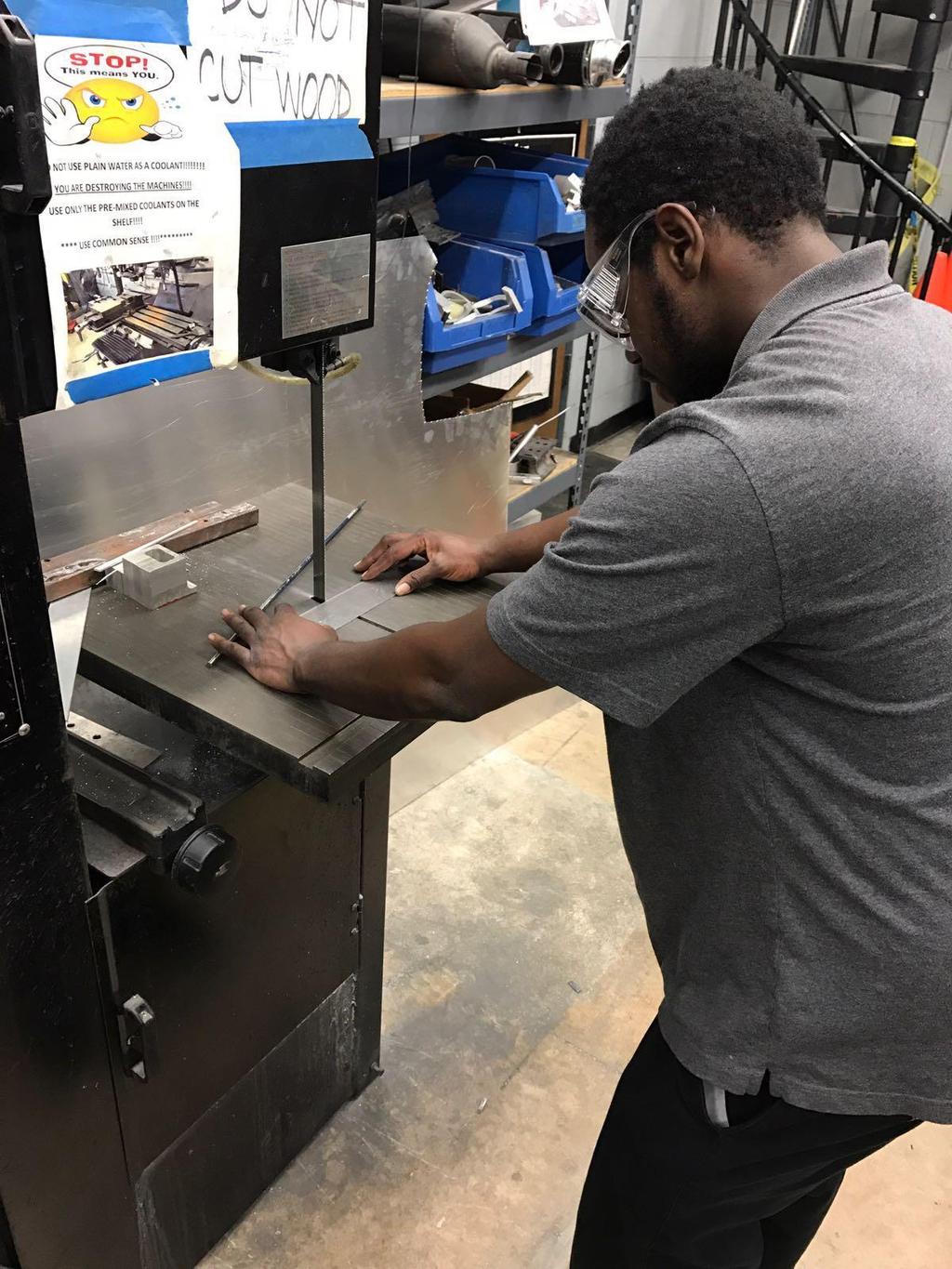
108 100
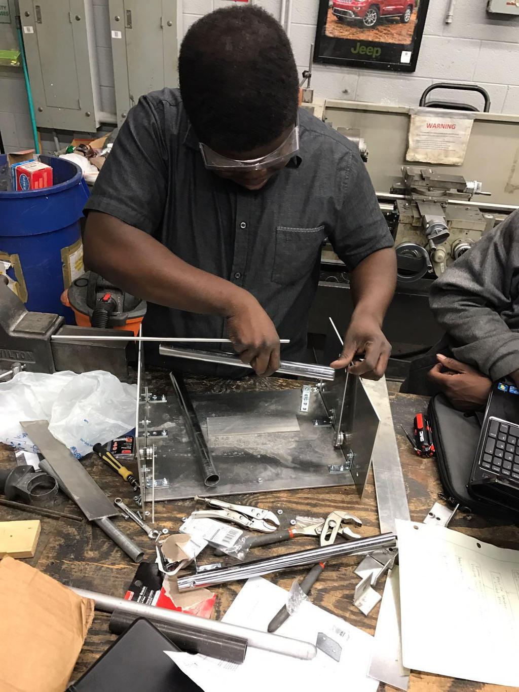
109 101
110 102
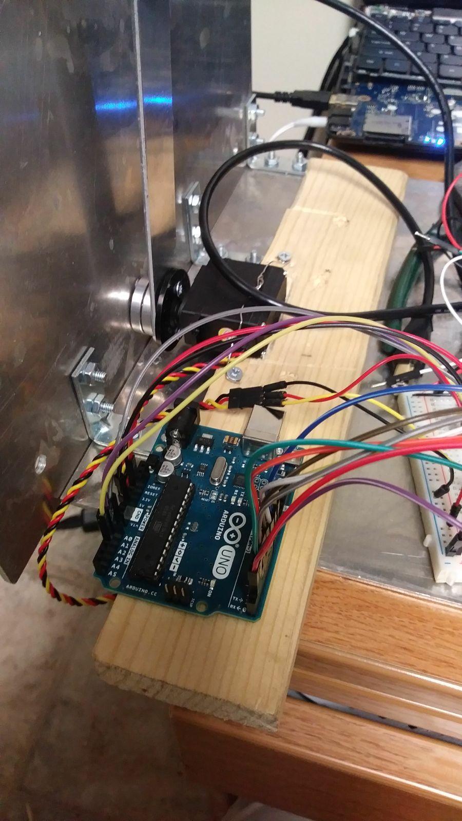
111 103
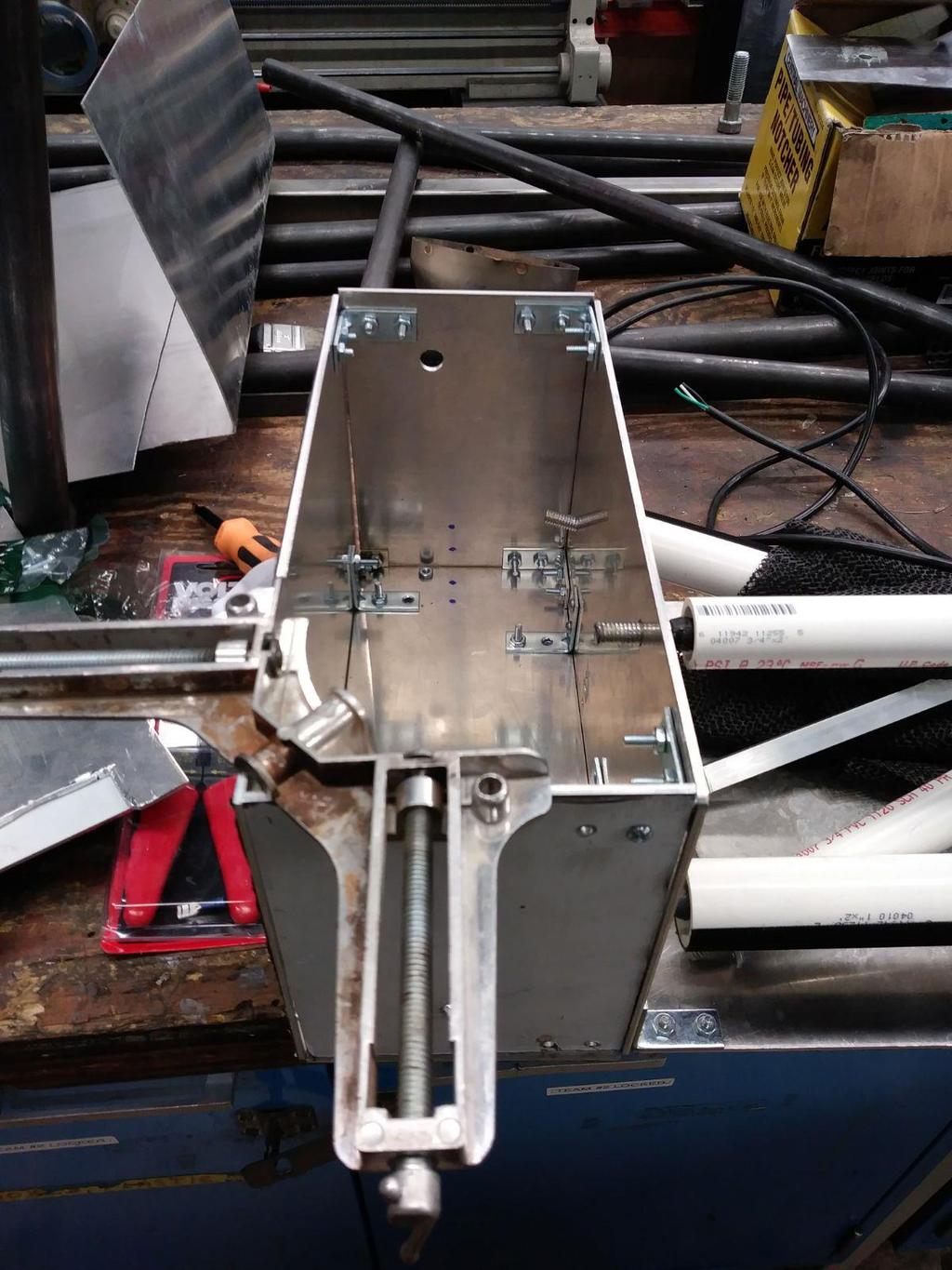
112 104
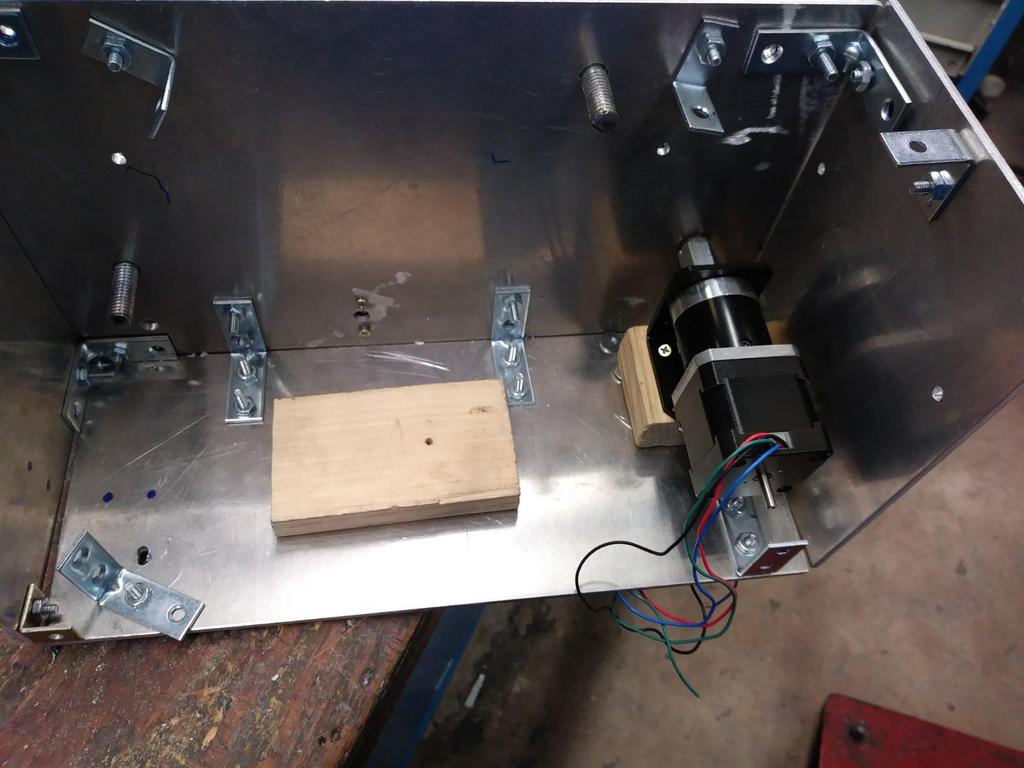
113 105

114 106
115 107
116 108
Application Note : Comparative Motor Technologies
 Application Note : Comparative Motor Technologies Air Motor and Cylinders Air Actuators use compressed air to move a piston for linear motion or turn a turbine for rotary motion. Responsiveness, speed
Experimental Validation of a Scalable Mobile Robot for Traversing Ferrous Pipelines
 Project Number: MQP TP1- IPG1 Experimental Validation of a Scalable Mobile Robot for Traversing Ferrous Pipelines A Major Qualifying Project (MQP) Submitted to the Faculty of WORCESTER POYTECHNIC INSTITUTE
Understanding the benefits of using a digital valve controller. Mark Buzzell Business Manager, Metso Flow Control
 Understanding the benefits of using a digital valve controller Mark Buzzell Business Manager, Metso Flow Control Evolution of Valve Positioners Digital (Next Generation) Digital (First Generation) Analog
ASME Human Powered Vehicle
 ASME Human Powered Vehicle By Yousef Alanzi, Evan Bunce, Cody Chenoweth, Haley Flenner, Brent Ives, and Connor Newcomer Team 14 Mid-Point Review Document Submitted towards partial fulfillment of the requirements
Gear Drive Solutions a Dedicated and Reliable Partner
 Gear Drive Solutions a Dedicated and Reliable Partner /// Gears, spindle gears, actuators, motors etc. /// Flange bearing and pillow block bearing units /// Standard or customized products /// Complete
Orbital Test Stand. By Mary Begay, Brett Booen, Calvin Boothe, James Ellis and Nicholas Garcia. Team 7. Project Proposal Document
 Orbital Test Stand By Mary Begay, Brett Booen, Calvin Boothe, James Ellis and Nicholas Garcia Team 7 Project Proposal Document Submitted towards partial fulfillment of the requirements for Mechanical Engineering
Selecting the Optimum Motion Control Solution for the Application By Festo Corporation
 Selecting the Optimum Motion Control Solution for the Application By Festo Corporation The successful machine builder develops products that offer superior price, performance, reliability, and the ability
Introduction: Problem statement
 Introduction: Problem statement The goal of this project is to develop a catapult system that can be used to throw a squash ball the farthest distance and to be able to have some degree of accuracy with
Proven to be better. Development trends in industrial rolling bearings
 Proven to be better Development trends in industrial rolling bearings Contents 1. General trends in power transmission and in machine construction and plant engineering Page 3 2. General trends in rolling
New Frontier in Energy, Engineering, Environment & Science (NFEEES-2018 ) Feb
 Feb") RESEARCH ARTICLE OPEN ACCESS DESIGN AND IMPACT ANALYSIS OF A ROLLCAGE FOR FORMULA HYBRID VEHICLE Aayush Bohra 1, Ajay Sharma 2 1(Mechanical department, Arya College of Engineering & I.T.,kukas, Jaipur)
RESEARCH ARTICLE OPEN ACCESS DESIGN AND IMPACT ANALYSIS OF A ROLLCAGE FOR FORMULA HYBRID VEHICLE Aayush Bohra 1, Ajay Sharma 2 1(Mechanical department, Arya College of Engineering & I.T.,kukas, Jaipur)
Bearings. Rolling-contact Bearings
 Bearings A bearing is a mechanical element that limits relative motion to only the desired motion and at the same time it reduces the frictional resistance to the desired motion. Depending on the design
M3 Design Product Teardown Kobalt Double-Drive Screwdriver
 19 Jun, 2013 Why do the product teardowns? M3 Design Product Teardown Kobalt Double-Drive Screwdriver Part of the product development process is to apply knowledge gained from prior experience during the
SAE Baja - Drivetrain
 SAE Baja - Drivetrain By Ricardo Inzunza, Brandon Janca, Ryan Worden Team 11A Concept Generation and Selection Document Submitted towards partial fulfillment of the requirements for Mechanical Engineering
Continuous Splicing Techniques
 Continuous Splicing Techniques R. Duane Smith Process Manager Web Handling & Specialty Winding Davis-Standard, LLC ICE USA 2017 Technical Conference April 26 th Trends for higher productivity Running Thinner
SAE Mini BAJA: Suspension and Steering
 SAE Mini BAJA: Suspension and Steering By Zane Cross, Kyle Egan, Nick Garry, Trevor Hochhaus Team 11 Progress Report Submitted towards partial fulfillment of the requirements for Mechanical Engineering
ECSE-2100 Fields and Waves I Spring Project 1 Beakman s Motor
 Names _ and _ Project 1 Beakman s Motor For this project, students should work in groups of two. It is permitted for groups to collaborate, but each group of two must submit a report and build the motor
External Hard Drive: A DFMA Redesign
 University of New Mexico External Hard Drive: A DFMA Redesign ME586: Design for Manufacturability Solomon Ezeiruaku 4-23-2013 1 EXECUTIVE SUMMARY The following document serves to illustrate the effects
FOLDING SHOPPING CART
 1 EDSGN 100: Introduction to Engineering Design Section 10 Team 6 FOLDING SHOPPING CART Submitted by: Kevin Chacha, Ugonna Onyeukwu, Patrick Thornton, Brian Hughes Submitted to: Xinli Wu October 28, 2013
TECHNICAL INFORMATION
 General Nomenclature Spherical Roller Bearings The spherical roller bearing is a combination radial and thrust bearing designed for taking misalignment under load When loads are heavy, alignment of housings
Stationary Bike Generator System
 Central Washington University ScholarWorks@CWU All Undergraduate Projects Undergraduate Student Projects Spring 2017 Stationary Bike Generator System Rakan Alghamdi Central Washington University, rk_rk11@hotmail.com
Propeller Blade Bearings for Aircraft Open Rotor Engine
 NTN TECHNICAL REVIEW No.84(2016) [ New Product ] Guillaume LEFORT* The Propeller Blade Bearings for Open Rotor Engine SAGE2 were developed by NTN-SNR in the frame of the Clean Sky aerospace programme.
Synthesis of Optimal Batch Distillation Sequences
 Presented at the World Batch Forum North American Conference Woodcliff Lake, NJ April 7-10, 2002 107 S. Southgate Drive Chandler, Arizona 85226-3222 480-893-8803 Fax 480-893-7775 E-mail: info@wbf.org www.wbf.org
DESIGN AND ANALYSIS OF PRE- INSERTION RESISTOR MECHANISM
 DESIGN AND ANALYSIS OF PRE- INSERTION RESISTOR MECHANISM Bhavik Bhesaniya 1, Nilesh J Parekh 2, Sanket Khatri 3 1 Student, Mechanical Engineering, Nirma University, Ahmedabad 2 Assistant Professor, Mechanical
Electromagnetic Fully Flexible Valve Actuator
 Electromagnetic Fully Flexible Valve Actuator A traditional cam drive train, shown in Figure 1, acts on the valve stems to open and close the valves. As the crankshaft drives the camshaft through gears
SIMULATION WORK ON AUTO-FEEDER BY SCISSOR LIFTER CONCEPT FOR DOOR PANELS PRODUCTION
 SIMULATION WORK ON AUTO-FEEDER BY SCISSOR LIFTER CONCEPT FOR DOOR PANELS PRODUCTION I. Nawi 1, B. A. M. Zain 1, O. Pauline 1, M. Ismon 2 and N. A. Zainudin 2 1 Advanced Dynamic Control Research Group,
Electric vs. Hydraulic Cylinders A Comparison of Technologies
 Electric vs. Hydraulic Cylinders A Comparison of Technologies Agenda: Electric vs. Hydraulic Cylinders Electric Value Proposition vs. Hydraulic Total Cost of Ownership Motion Control Capabilities System
LESSON Transmission of Power Introduction
 LESSON 3 3.0 Transmission of Power 3.0.1 Introduction Earlier in our previous course units in Agricultural and Biosystems Engineering, we introduced ourselves to the concept of support and process systems
Remote Control Helicopter. Engineering Analysis Document
 Remote Control Helicopter By Abdul Aldulaimi, Travis Cole, David Cosio, Matt Finch, Jacob Ruechel, Randy Van Dusen Team 04 Engineering Analysis Document Submitted towards partial fulfillment of the requirements
Capstone Design Project: Developing the Smart Arm Chair for Handicapped People
 Capstone Design Project: Developing the Smart Arm Chair for Handicapped People Kwang Sun Kim 1, Jun Young Kim 2, Kyung Min Jang 3 and Kang Wo Joo 4 1 School of Mechatronics Engineering, Korea University
FSAE SUSPENSION SYSTEM
 EML 4905 Senior Design Project A B.S. THESIS PREPARED IN PARTIAL FULFILLMENT OF THE REQUIREMENT FOR THE DEGREE OF BACHELOR OF SCIENCE IN MECHANICAL ENGINEERING FSAE SUSPENSION SYSTEM Michael Benitez Yussimil
Linear Induction Motor (LIMO) Modular Test Bed for Various Applications
 Modular Test Bed for Various Applications") Linear Induction Motor (LIMO) Modular Test Bed for Various Applications ECE 4901 Senior Design I Fall 2013 Fall Project Report Team 190 Members: David Hackney Jonathan Rarey Julio Yela Faculty Advisor
Linear Induction Motor (LIMO) Modular Test Bed for Various Applications ECE 4901 Senior Design I Fall 2013 Fall Project Report Team 190 Members: David Hackney Jonathan Rarey Julio Yela Faculty Advisor
FEASIBILITY STYDY OF CHAIN DRIVE IN WATER HYDRAULIC ROTARY JOINT
 FEASIBILITY STYDY OF CHAIN DRIVE IN WATER HYDRAULIC ROTARY JOINT Antti MAKELA, Jouni MATTILA, Mikko SIUKO, Matti VILENIUS Institute of Hydraulics and Automation, Tampere University of Technology P.O.Box
LANSCE WIRE SCANNING DIAGNOSTICS DEVICE MECHANICAL DESIGN
 LANSCE WIRE SCANNING DIAGNOSTICS DEVICE MECHANICAL DESIGN Sergio Rodriguez Esparza, Los Alamos National Laboratory, Los Alamos, NM USA INTRODUCTION The Los Alamos Neutron Science Center (LANSCE) is one
Folding Shopping Cart Design Report
 Folding Shopping Cart Design Report EDSGN 100 Section 010, Team #4 Submission Date- 10/28/2013 Group Image with Prototype Submitted by: Arafat Hossain, Mack Burgess, Jake Covell, and Connor Pechko (in
Magnetostrictive Actuator
 Magnetostrictive Actuator Project Proposal Randall Bateman, Aaron Bolyen, Chris Cleland Alex Lerma, Xavier Petty, Michael Roper December 11, 2015 Overview Introduction Need Statement/Goals Constraints
Stationary Bike Generator System (Drive Train)
") Central Washington University ScholarWorks@CWU All Undergraduate Projects Undergraduate Student Projects Summer 2017 Stationary Bike Generator System (Drive Train) Abdullah Adel Alsuhaim cwu, 280zxf150@gmail.com
Central Washington University ScholarWorks@CWU All Undergraduate Projects Undergraduate Student Projects Summer 2017 Stationary Bike Generator System (Drive Train) Abdullah Adel Alsuhaim cwu, 280zxf150@gmail.com
RACK JACK. Synchronous Lifting Systems
 RACK JACK Synchronous Lifting Systems RACK JACK (ROUND RACK TYPE) Operation The Rack Jack from WMH Herion provides simple synchronous lifting motion. The system of rack and pinion transforms linear motion
CHAPTER THREE DC MOTOR OVERVIEW AND MATHEMATICAL MODEL
 CHAPTER THREE DC MOTOR OVERVIEW AND MATHEMATICAL MODEL 3.1 Introduction Almost every mechanical movement that we see around us is accomplished by an electric motor. Electric machines are a means of converting
SAE Baja - Drivetrain
 SAE Baja - Drivetrain By Ricardo Inzunza, Brandon Janca, Ryan Worden Team 11 Engineering Analysis Document Submitted towards partial fulfillment of the requirements for Mechanical Engineering Design I
Mechanical Considerations for Servo Motor and Gearhead Sizing
 PDHonline Course M298 (3 PDH) Mechanical Considerations for Servo Motor and Gearhead Sizing Instructor: Chad A. Thompson, P.E. 2012 PDH Online PDH Center 5272 Meadow Estates Drive Fairfax, VA 22030-6658
Composite Long Shaft Coupling Design for Cooling Towers
 Composite Long Shaft Coupling Design for Cooling Towers Junwoo Bae 1,#, JongHun Kang 2, HyoungWoo Lee 2, Seungkeun Jeong 1 and SooKeun Park 3,* 1 JAC Coupling Co., Ltd., Busan, South Korea. 2 Department
Advanced Electromechanical Actuation Components to Solutions Systems
 Advanced Electromechanical Actuation Components to Solutions Systems Components to Solutions For over 25 years, Exlar has been providing advanced and robust electromechanical actuators for applications
Stopping Accuracy of Brushless
 Stopping Accuracy of Brushless Features of the High Rigidity Type DGII Series Hollow Rotary Actuator The DGII Series hollow rotary actuator was developed for positioning applications such as rotating a
Variable Valve Drive From the Concept to Series Approval
 Variable Valve Drive From the Concept to Series Approval New vehicles are subject to ever more stringent limits in consumption cycles and emissions. At the same time, requirements in terms of engine performance,
Racing Tires in Formula SAE Suspension Development
 The University of Western Ontario Department of Mechanical and Materials Engineering MME419 Mechanical Engineering Project MME499 Mechanical Engineering Design (Industrial) Racing Tires in Formula SAE
Members: Sponsor: Dalton Hamilton Preston-Eastin Levi Edens Kenneth Mui Brice Abbott
 Members: Dalton Hamilton Levi Edens Brice Abbott Sponsor: Preston-Eastin Kenneth Mui Mission Statement Wolf Pack Engineering strives to provide our customer with innovative solutions. We take the problem
RAT PACK RAT TREADMILL COLIN BURKHALTER, STU SATER, STEPHEN SCHOONEN, MITCHELL WILLIAMS
 RAT PACK RAT TREADMILL COLIN BURKHALTER, STU SATER, STEPHEN SCHOONEN, MITCHELL WILLIAMS INTRODUCTION/BACKGROUND Project Objective: To redesign and fabricate an improved neonatal rat research treadmill
Harmonic Analysis of Reciprocating Compressor Crankcase Assembly
 IOSR Journal of Engineering (IOSRJEN) www.iosrjen.org ISSN (e): 2250-3021, ISSN (p): 2278-8719 PP 16-20 Harmonic Analysis of Reciprocating Compressor Crankcase Assembly A. A. Dagwar 1, U. S. Chavan 1,
KISSsys Application 008: Gearbox Concept Analysis
 KISSsoft AG Frauwis 1 CH - 8634 Hombrechtikon Telefon: +41 55 264 20 30 Calculation Software for Machine Design Fax: +41 55 264 20 33 www.kisssoft.ch info@kisssoft.ch 1. Abstract KISSsys: Efficient Drivetrain
USE AN ENGINEERED APPROACH TO TAILOR A PERFECT STANDARD GAS SPRING FOR YOUR DESIGN A GUIDE TO GAS SPRING DESIGN AND CUSTOMIZATION WH ITE PA P E R
 WH ITE PA P E R USE AN ENGINEERED APPROACH TO TAILOR A PERFECT STANDARD GAS SPRING FOR YOUR DESIGN A GUIDE TO GAS SPRING DESIGN AND CUSTOMIZATION When your machine design calls for an industrial gas spring,
Dunkermotoren VENETIAN BLIND DRIVES
 Dunkermotoren VENETIAN BLIND DRIVES Your Partner for accuracy, compact and high efficient motion solutions. Synergy effects through:» Quick availability of samples and prototypes» Qualified systems for
MARITIME AFTERNOON. Torben Ole Andersen. June 14, 2017 Aalborg University, Denmark
 MARITIME AFTERNOON HYDRAULICS Torben Ole Andersen June 14, 2017 Aalborg University, Denmark Agenda Marine Propellers Digital Hydraulics in a Hydraulic Winch Secondary Control in of Multi -Chamber Cylinders
A Simple and Scalable Force Actuator
 A Simple and Scalable Force Actuator Eduardo Torres-Jara and Jessica Banks Computer Science and Artificial Intelligence Laboratory Massachusetts Institute of Technology 200 Technology Square, Cambridge,
Automated Seat Belt Switch Defect Detector
 pp. 10-16 Krishi Sanskriti Publications http://www.krishisanskriti.org/publication.html Automated Seat Belt Switch Defect Detector Department of Electrical and Computer Engineering, Sri Lanka Institute
White paper: Pneumatics or electrics important criteria when choosing technology
 White paper: Pneumatics or electrics important criteria when choosing technology The requirements for modern production plants are becoming increasingly complex. It is therefore essential that the drive
Static And Modal Analysis of Tractor Power Take Off (PTO) Gearbox Housing
 Gearbox Housing") Static And Modal Analysis of Tractor Power Take Off (PTO) Gearbox Housing Gopali S Lamani 1, Prof: S.R.Basavaraddi 2, Assistant Professor, Department of Mechanical Engineering, JSPM NTC RSSOER,India1 Professor,
Static And Modal Analysis of Tractor Power Take Off (PTO) Gearbox Housing Gopali S Lamani 1, Prof: S.R.Basavaraddi 2, Assistant Professor, Department of Mechanical Engineering, JSPM NTC RSSOER,India1 Professor,
TRANSLATION (OR LINEAR)
") 5) Load Bearing Mechanisms Load bearing mechanisms are the structural backbone of any linear / rotary motion system, and are a critical consideration. This section will introduce most of the more common
5) Load Bearing Mechanisms Load bearing mechanisms are the structural backbone of any linear / rotary motion system, and are a critical consideration. This section will introduce most of the more common
ALCOA Project Design Engineering Design 009 Team 7 12/16/13 Submitted to Wallace Catanach
 ALCOA Project Design Engineering Design 009 Team 7 12/16/13 Submitted to Wallace Catanach Tim O Neill (tjo5125@psu.edu) Jacob Eaton (jne5074@psu.edu) Andrew McDonagh (apm186@psu.edu) Bryan O Donnell (byo5060@psu.edu)
COMPUTATIONAL ANALYSIS OF TWO DIMENSIONAL FLOWS ON A CONVERTIBLE CAR ROOF ABDULLAH B. MUHAMAD NAWI
 COMPUTATIONAL ANALYSIS OF TWO DIMENSIONAL FLOWS ON A CONVERTIBLE CAR ROOF ABDULLAH B. MUHAMAD NAWI Report submitted in partial of the requirements for the award of the degree of Bachelor of Mechanical
Flywheel energy storage retrofit system
 Flywheel energy storage retrofit system for hybrid and electric vehicles Jan Plomer, Jiří First Faculty of Transportation Sciences Czech Technical University in Prague, Czech Republic 1 Content 1. INTRODUCTION
F.I.R.S.T. Robotic Drive Base
 F.I.R.S.T. Robotic Drive Base Design Team Shane Lentini, Jose Orozco, Henry Sick, Rich Phelan Design Advisor Prof. Sinan Muftu Abstract F.I.R.S.T. is an organization dedicated to inspiring and teaching
Direct Drive Rotary An Increasingly Attractive Servo Choice
 Direct Drive Rotary An Increasingly Attractive Servo Choice DDR systems are available in frameless, housed and the newly developed Cartridge motor format. While many engineers are familiar with the basics
Fundamentals of Engineering High-Performance Actuator Systems. Kenneth W. Hummel
 Fundamentals of Engineering High-Performance Actuator Systems Kenneth W. Hummel Author Name Chapter 1: Introduction...1 1.1 Fundamentals... 2 1.2 Performance... 2 1.3 Loads... 3 1.4 Constraints... 3 1.5
ULTRALIGHT TRANSFERS TECHNICAL PRESENTATION
 ULTRALIGHT TRANSFERS TECHNICAL PRESENTATION 012118 The Company Since its creation in 1979, Misati has designed and manufactured high-quality pneumatic fastening elements, also known as pincers & pneumatic
AUTOMATIC CLOSING WINDOW
 MECHANICAL ENGINEERING DEPARTMENT AUTOMATIC CLOSING WINDOW ASSESSMENT III- GRADUATION PROJECT Advisor: Dr. Emad Y. Tanbour Mohd. Abdul Mohsin Khan Mohd. Al- Ghamdi Nemer Saab Contents Introduction Problem
INTRODUCTION Team Composition Electrical System
 IGVC2015-WOBBLER DESIGN OF AN AUTONOMOUS GROUND VEHICLE BY THE UNIVERSITY OF WEST FLORIDA UNMANNED SYSTEMS LAB FOR THE 2015 INTELLIGENT GROUND VEHICLE COMPETITION University of West Florida Department
IT'S MAGNETIC (1 Hour)
") IT'S MAGNETIC (1 Hour) Addresses NGSS Level of Difficulty: 4 Grade Range: 3-5 OVERVIEW In this activity, students will create a simple electromagnet using a nail, a battery, and copper wire. They will
IT'S MAGNETIC (1 Hour) Addresses NGSS Level of Difficulty: 4 Grade Range: 3-5 OVERVIEW In this activity, students will create a simple electromagnet using a nail, a battery, and copper wire. They will
Smart Spinner. Age 7+ Teacher s Notes. In collaboration with NASA
 Smart Spinner Age 7+ Teacher s Notes In collaboration with NASA LEGO and the LEGO logo are trademarks of the/sont des marques de commerce de/son marcas registradas de LEGO Group. 2012 The LEGO Group. 190912
Focus Area Level Report Including Knowledge and Skills, and Performance Indicators
 Including Knowledge and Skills, and PST 01. Use physical science principles and engineering applications with power, structural and technical systems to solve problems and improve performance. PST 01.01.
STEAM TURBINE MODERNIZATION SOLUTIONS PROVIDE A WIDE SPECTRUM OF OPTIONS TO IMPROVE PERFORMANCE
 STEAM TURBINE MODERNIZATION SOLUTIONS PROVIDE A WIDE SPECTRUM OF OPTIONS TO IMPROVE PERFORMANCE Michael W. Smiarowski, Rainer Leo, Christof Scholten, Siemens Power Generation (PG), Germany John Blake,
Seals Stretch Running Friction Friction Break-Out Friction. Build With The Best!
 squeeze, min. = 0.0035 with adverse tolerance build-up. If the O-ring is made in a compound that will shrink in the fluid, the minimum possible squeeze under adverse conditions then must be at least.076
Finite Element Modeling and Analysis of Vehicle Space Frame with Experimental Validation
 Finite Element Modeling and Analysis of Vehicle Space Frame with Experimental Validation Assoc. Prof Dr. Mohammed A.Elhaddad Mechanical Engineering Department Higher Technological Institute, Town of 6
FEM Analysis of Combined Paired Effect on Piston & Connecting Rod using ANSYS
 FEM Analysis of Combined Paired Effect on Piston & Connecting Rod using ANSYS Kunal Saurabh Assistant Professor, Mechanical Department IEC Group of Institutions, Greater Noida - India kunalsaurabh.me@ieccollege.com
Design of Alternative Automatic Transmission for Electric Mopeds Ameya Bhusari 1, Saurabh Rege 2
 Design of Alternative Automatic Transmission for Electric Mopeds Ameya Bhusari 1, Saurabh Rege 2 1 Department of Mechanical, Maharashtra Institute of Technology, PUNE-38 2 Department of Mechanical, Modern
INDIAN INSTITUTE OF TECHNOLOGY KHARAGPUR NPTEL ONLINE CERTIFICATION COURSE. On Industrial Automation and Control
 INDIAN INSTITUTE OF TECHNOLOGY KHARAGPUR NPTEL ONLINE CERTIFICATION COURSE On Industrial Automation and Control By Prof. S. Mukhopadhyay Department of Electrical Engineering IIT Kharagpur Topic Lecture
Step Motor. Mechatronics Device Report Yisheng Zhang 04/02/03. What Is A Step Motor?
 Step Motor What is a Step Motor? How Do They Work? Basic Types: Variable Reluctance, Permanent Magnet, Hybrid Where Are They Used? How Are They Controlled? How To Select A Step Motor and Driver Types of
Design of Back stopper Mechanism for Automobiles
 Design of Back stopper Mechanism for Automobiles Sneha.H.Dhoria #1, B.Sandeep #2, G.Narendra Santosh Kumar #3, M.Srivatsava #4 #1,2 Assistant Professor, Department of Mechanical Engineering, R.V.R& JC
REU: Improving Straight Line Travel in a Miniature Wheeled Robot
 THE INSTITUTE FOR SYSTEMS RESEARCH ISR TECHNICAL REPORT 2013-12 REU: Improving Straight Line Travel in a Miniature Wheeled Robot Katie Gessler, Andrew Sabelhaus, Sarah Bergbreiter ISR develops, applies
Wind Energy Solutions
 Wind Energy Solutions Around the world, wind turbine designers and operators are turning to Timken for power transmission and friction management solutions that increase uptime and improve total system
Using Hydraulic Systems
 Lesson A6 7 Using Hydraulic Systems Unit A. Mechanical Systems and Technology Problem Area 6. Agricultural Power Systems Lesson 7. Using Hydraulic Systems New Mexico Content Standard: Pathway Strand: Power,
EMC-HD. C 01_2 Subheadline_15pt/7.2mm
 C Electromechanical 01_1 Headline_36pt/14.4mm Cylinder EMC-HD C 01_2 Subheadline_15pt/7.2mm 2 Elektromechanischer Zylinder EMC-HD Short product name Example: EMC 085 HD 1 System = ElectroMechanical Cylinder
Robotic Device for Cleaning of Photovoltaic Arrays V2
 Robotic Device for Cleaning of Photovoltaic Arrays V2 Design Team Greg Belogolovsky, Steve Bennett, Istvan Hauer, Salome Morales, Leonid Nemiro Design Advisor Constantinos Mavroidis, Ph.D. Richard Ranky,
Building Blocks of Automation
 Building Blocks of Automation Manufacturing systems can generally be classified as fixed (hardware) or flexible (software). These classifications are normally bestowed on both the processing equipment
1 a) Not complying with the requirements of the Health and Safety at Work Act can have serious consequences.
 Not complying with the requirements of the Health and Safety at Work Act can have serious consequences.") Qualification title: Level 2 Technical Certificate in Automotive (4292-21) Exam title: Externally set, externally marked Version: Past Paper Base mark: 65 1 a) Not complying with the requirements of the
Qualification title: Level 2 Technical Certificate in Automotive (4292-21) Exam title: Externally set, externally marked Version: Past Paper Base mark: 65 1 a) Not complying with the requirements of the
Design, Cad Modeling & Fabrication of Geneva Operated Roller Conveyor
 Design, Cad Modeling & Fabrication of Geneva Operated Roller Conveyor Mr M. V. Ingalkar 1, Mr A. R. Sonekar 2, Mr Y. D. Bansod 3 Lecturer in Mechanical Engineering Department P. R. Patil Institute of Polytechnic
Artesis MCM Case Studies. March 2011
 Artesis MCM Case Studies March 2011 Case 1 Automotive Company: Automobile Manufacturer A Equipment: Pump Stator Isolation Breakdown Decreasing current unbalance level Case 1 Automotive Company: Automobile
Beyond Standard. Dynamic Wheel Endurance Tester. Caster Concepts, Inc. Introduction: General Capabilities: Written By: Dr.
 Dynamic Wheel Endurance Tester Caster Concepts, Inc. Written By: Dr. Elmer Lee Introduction: This paper details the functionality and specifications of the Dynamic Wheel Endurance Tester (DWET) developed
Simulating Rotary Draw Bending and Tube Hydroforming
 Abstract: Simulating Rotary Draw Bending and Tube Hydroforming Dilip K Mahanty, Narendran M. Balan Engineering Services Group, Tata Consultancy Services Tube hydroforming is currently an active area of
Shaft Grounding and Sliding Electrical Contacts
 Shaft Grounding and Sliding Electrical Contacts Jeff D. Koenitzer, P.E. Vice President - Engineering December 2016 Milwaukee, Wisconsin, USA Introduction A sliding electrical contact is a component that
DESIGN CONSIDERATIONS FOR ROTATING UNIONS SEALING TECHNOLOGIES
 DESIGN CONSIDERATIONS FOR ROTATING UNIONS SEALING TECHNOLOGIES Rotating unions convey fluid from a stationary supply line to equipment or a rotating tool. They are critical elements in a variety of applications
CSDA Best Practice. Hi-Cycle Concrete Cutting Equipment. Effective Date: Oct 1, 2010 Revised Date:
 CSDA Best Practice Title: Hi-Cycle Concrete Cutting Equipment Issue No: CSDA-BP-010 : Oct 1, 2010 Revised : Introduction Hi-cycle/high frequency concrete cutting equipment has become more prevalent in
Design and Analysis of Pressure Die Casting Die for Side Differential Cover of Mini truck
 Design and Analysis of Pressure Die Casting Die for Side Differential Cover of Mini truck 1 A Chakravarthi P.G student, Department of Mechanical Engineering,KSRM CE, kadapa-516003 2. R Rama Krishna Reddy,
MSMA LATERAL LOADING DEVICE
 MSMA LATERAL LOADING DEVICE PROJECT PROPOSAL Presented by: Matthew Batten, Cody Burbank, Jonathan McCurdy, Thaddeus Grudniewksi, & Joy Weber December 10, 2013 Overview I. Problem Identification II. MSMA
Applications in Design & Engine. Analyzing Compound, Robotic Machines
 v2.1 Compound Machines ering Applications in Design & Engine Analyzing Compound, Robotic Machines Educational Objectives At the conclusion of this lesson, students should be able to: Understand the relationship
Six keys to achieving better precision in linear motion control applications
 profile Drive & Control Six keys to achieving better precision in linear motion control applications Achieving precise linear motion Consider these factors when specifying linear motion systems: Equipped
ME 455 Lecture Ideas, Fall 2010
 ME 455 Lecture Ideas, Fall 2010 COURSE INTRODUCTION Course goal, design a vehicle (SAE Baja and Formula) Half lecture half project work Group and individual work, integrated Design - optimal solution subject
PC-Series Precision Linear Actuators. Optimize Your Machine and Save Energy With Reliable, High Performance, Compact Actuators
 PC-Series Precision Linear Actuators Optimize Your Machine and Save Energy With Reliable, High Performance, Compact Actuators Make the Change to Electric Enjoy superior performance and save time and energy
More Than Just a Motor Company
 More Than Just a Motor Company RIGHT-ANGLE AND PARALLEL SHAFT AC & DC GEARMOTORS FRACTIONAL AND SUB-FRACTIONAL HORSEPOWER Bulletin 1830 GEARMOTORS Your First Source for Off-The-Shelf or Custom Gearmotors
ITT Industrial Products
 ITT Industrial Products Providing custom industrial solutions to meet customers application needs globally. ITT Control Technologies GmbH under the ITT Enidine brand provides quality energy absorption
Instructor Training Manual. Chapter 6 HYDRAULICS & PNEUMATICS
 Instructor Training Manual Chapter 6 HYDRAULICS & PNEUMATICS Learning Objectives 1. The purpose of this chapter is to provide a basic introduction to the principles of hydraulics & pneumatics and their