Table of Contents. Safety Procedures...2. Warranty...3. Placement and Installation Electrical Connection Visual Display Setup...
|
|
|
- Ezra Austin
- 5 years ago
- Views:
Transcription
1 Table of Contents Topic Page Safety Procedures...2 Warranty...3 Placement and Installation Electrical Connection...10 Visual Display Setup...11 Control Board Layout...12 Control Board Wiring Diagram...13 Alarm Board Wiring Diagram...14 Maintenance...15 Handle Diagram...16 Bar Graph Service Indicator Coin/Bill counter. 19 Alarm...20 Microcoin QL Instruction Page...21 MA-820 Instruction Page
2 Safety Procedures IMPORTANT SAFETY INSTRUCTIONS READ ALL INSTRUCTIONS BEFORE USING THIS APPLIANCE WARNING: TO REDUCE THE RISK OF FIRE, ELECTRICAL SHOCK OR INJURY: Use only manufacturer s options and attachments. Do not spray near open flame. Do not spray on electrical equipment. If any disposal of product is necessary, adhere to all local, state and federal laws governing its disposal. Avoid contact with skin and eyes. Do not spray directly on plastic or vinyl surfaces. DANGER: This equipment incorporates parts such as switches, motors, or the like that tend to produce arcs or sparks which can cause an explosion. When located in gasoline dispensing and service stations install and use at least 20 feet horizontally from the exterior enclosure of any pump and at least 18 inches above driveway or ground level. PAGE 2
3 Limited Warranty Fragra*Matics Mfg. Co., Inc. warrants its equipment against defects in workmanship and material and will remedy any defect according to the terms of this Limited Warranty. Fragra*Matics will repair or replace at its option, any defective part(s) or component(s) for a period of one (1) year from the date of purchase. This Limited Warranty extends to the original purchaser only. Fragra*Matics will repair or replace at its option, any defective vacuum motors for a period of six (6) months from the date of purchase. This Limited Warranty extends to the original purchaser only. This Limited Warranty does not cover equipment that has been damaged due to misuse, mis-application, attempted theft, vandalism, accident, connection to an improper voltage supply or as a result of modification by other than Fragra*Matics. Components such as hose and handle assemblies, vacuum hoses and nozzles, filters, gaskets, electrical components, rubber, plastic parts, or similar items are subject to wear or consumption during normal operation and this normal disintegration is not covered by the Limited Warranty. Fragra*Matics makes no warranty concerning the compliance of the equipment with any local, state, or federal/national laws or regulations. The purchaser agrees to accept full responsibility for complying with such laws. There are no warranties other than those on the face hereof described above and they are in lieu of all other warranties whether expressed or implied, including but not limited to the implied warranties of merchantability and fitness for particular purpose. Fragra*Matics Mfg. Co., Inc. shall not be liable for incidental, special, or consequential damages including without limitation damages resulting from personal, bodily injury or death or damages to or loss of use of property. Returns To make a request or claim for service under the terms of this warranty, the original purchaser must contact Fragra*Matics and provide the product serial number, a description of the problem (including some indication of the part(s) or component(s) felt to be defective) and the date of purchase. No parts, components or the equipment should be returned without authorization from Fragra*Matics. The original purchaser shall be responsible for all shipping charges. Any item authorized by Fragra*Matics for return under the terms of this Limited Warranty must be shipped prepaid, in the original shipping container or equivalent to Fragra*Matics or to a local service center as authorized and determined by Fragra*Matics. The purchaser assumes the risk of loss or damage in transit. (Please refer to your owner s manual or contact Fragra*Matics if you need further information about proper shipping procedures). Replacement or repair of parts or components in accordance with the above Limited Warranty shall be the purchaser s sole and exclusive remedy against Fragra*Matics. PAGE 3

4 Proper Placement Consider vehicle traffic, ease of access, weather protection and lighting to enhance vacuum serviceability and income. Refer to SAFETY INSTRUCTIONS sheet in this manual for restrictions concerning placement of these units in gasoline dispensing locations and service stations. For vacuum island layouts, see next four (4) pages. CAUTION ELECTRICAL SHOCK HAZARD DISCONNECT POWER PRIOR TO BEGINNING ANY SERVICE OR INSTALLATION WORK. CONTACT A TRAINED ELECTRICIAN IF YOU ARE UNSURE OF THESE PROCEDURES. Site Planning Select and prepare a solid, level site for a concrete or similar base. Consult local codes for foundation requirements. Note: We recommend base height above grade. To protect your island investment place bollards 18 from each corner of the Vac Island. Always protect your investment with bollards. Bollard (4 Reqd.) Must be at 45 degree angle from island corner PAGE 4
5 Vacuum Island Layout Trash Typical Layout Brick or Concrete PAGE 5

6 Vacuum Island Layout Typical concrete base with Fragramatics canopy PAGE 6


")
7 Island Base Layout Fragramatics Stainless Steel Dual 108 Island Meets ADA Requirements (American Disabilities Act) FV3 21 7/ PAGE 7
8 Island Base Layout FV3 Incorporates 32 Gallon Standard Garbage can Note: Ensure top surface of pad is level. Figure 1 Concrete Pad 6 Thick Vacuum Power 30 Amp Canopy Power 10 Amp Allowable Stub-In Areas TYPICAL BOTH ENDS OF PAD 6 Sloped Site 1 Minimum 4 Maximum Exposure Above Grade Level Site ½ Exposure Above Grade PAGE 8
 while forming concrete or masonry base.")

9 Guide to Easy Installation Using J Bolts: J-Bolts (new construction only). Carefully locate 4 J bolts (not provided) while forming concrete or masonry base. The plywood shipping base can be used as a locating fixture for the J bolts while the concrete is formed. See illustration to the left. Masonry Anchors: Anchors are used for existing construction only. Drill and install suitable masonry anchors to accommodate a 3/8 inch lag screw. Check anchor supplier information for proper drill size. HINT: Use the plywood base as a template for drilling the anchoring pilot holes. See illustration to the left. PAGE 9

10 Electrical Connection IMPORTANT SAFETY INSTRUCTIONS READ ALL INSTRUCTIONS BEFORE USING APPLIANCE. Connect to electrical service. All units require a 30 amp breaker and #10 awg. Check local codes and requirements and refer to IMPORTANT SAFETY INSTRUCTIONS sheet in this manual. CAUTION ELECTRICAL SHOCK HAZARD. DISCONNECT POWER PRIOR TO BEGINNING ANY SERVICE OR INSTALLATION WORK. GET ASSISTANCE IF YOU ARE UNSURE OF THESE PROCEDURES. Connect to properly grounded 30 amp, 120 VAC 60 Hz power source. Installation should only be performed by a qualified electrician. The electrical power should be stubbed in under the 18 vacuum tank cylinder (refer to installation instructions). Maintain approximately 2 of clearance from the edge of the vacuum cylinder. There is 4 of vertical clearance from the mounting surface to the underside of the vacuum. Route the power cable through either of the holes in the vacuum tank wall, through the cabinet front to the electrical connection box. The cable should be inserted through the grommet at the base of the junction box. Connect the three wires: black (power), white (common), and green (ground) to the corresponding leads found inside the box. Finally, replace both the clear plastic and metal cover. THIS IS THE ONLY ELECTRICAL CONNECTION NECESSARY. Power cable routing through vacuum tank wall to cabinet Electrical power connection to unit must be made in this junction box. * PAGE 10
 in Figure B. WITH POWER OFF! Step 2: Connect additional tubing to Visual Barb #2 & drop into visual fluid.")


11 Fill Visual VISUAL PUMP Step 1: Connect Tube #1 (the inlet tube from the pump) to Visual Barb #1 on Cylinder #1 (Cylinder closest to door hinge) in Figure B. WITH POWER OFF! Step 2: Connect additional tubing to Visual Barb #2 & drop into visual fluid. Turn power on creating suction and allowing fluid to fill the cylinder. A Repeat Steps 1 & 2 for others colors, filling cylinders 2 & 3. *Additional tubing to fill visual only. Step 3: Re-Affix sleeve onto Visual Barbs, tightening hand tight. Use arrows as flow guide. B NO TOOLS REQUIRED Photo on left shows completed visual display. To Empty Visual Display: Connect Tube #2 (outlet tube from the pump) in Figure A to Visual Barb #1 in Figure B. Turn power on to create pressure that will push out the visual fluid. PAGE 11
 5-Amp Fuse (115 VAC) Primary to the Transformer, Compressor 4) Green Fuse Indicator LED *Lit(2-Amp fuse is good) 5) Yellow Fuse Indicator LED *Lit(3-Amp fuse is")
12 Control Board 1) 2-Amp Fuse (24 VDC) Fuse for Relays located on the Relay Board 2) 3-Amp Fuse (24 VAC) Secondary to the Transformer, Under Cabinet Light, Bill Acceptor/Coin Acceptor, Controller, Fragrance Valves, Diverter Valve 3) 5-Amp Fuse (115 VAC) Primary to the Transformer, Compressor 4) Green Fuse Indicator LED *Lit(2-Amp fuse is good) 5) Yellow Fuse Indicator LED *Lit(3-Amp fuse is good) 6) Red Fuse Indicator LED *Lit(5-Amp fuse is good) 7) Main Circuit Breaker 8) Turbo-Vac Fuse 15-Amp 9) Super-Vac Fuse 15-Amp 10) Hidden Alarm Reset Switch 11) Smart Card (Must stay in machine at all times.) 12) Battery Indicator LED *Red: Alarm Battery is charging *Green: Alarm Battery is fully charged. *Not Lit: battery has discharged below 10.50V, the battery isn t connected, or the 115 VAC power connection has been lost. PAGE 12
13 Control Board Wiring Diagram PAGE 13
14 Alarm Board Wiring Diagram PAGE 14


 from your distributor to simplify this process. Empty & shake bags weekly.")
15 Maintenance Exterior & Vacuum General Maintenance: Keep the outer appearances of the unit looking good by using a glass cleaner to clean the front door decal and lexan faceplate in front of visual display. Apply a stainless steel polish to the cabinet to maintain the appearance. Take care not to use abrasive cleaners or rags for these applications to avoid scratching the surfaces. *DO NOT USE STEEL WOOL OR OTHER FERROUS BRUSHES TO CLEAN STAINLESS STEEL SURFACES. The visual display fluid should be maintained at approximately 60% of cylinder height. The visual pumps should be replaced as necessary in order to assure that all cylinders are operating properly. Add fluid as needed. Check motor brushes for wear and replace as necessary. Inspect gaskets and replace with factory replacements. IMPORTANT! ONE TAMPER PROOF WRENCH IS INCLUDED WITH YOUR UNIT. THIS IS USED FOR REMOVAL OF DOME. SAVE FOR FUTURE USE! Daily/Weekly Maintenance: Remove dirt & debris from vacuum. HINT: Consider ordering a debris catcher (VAC-067) from your distributor to simplify this process. Empty & shake bags weekly. Exchange bags and wash bi-monthly. Check hand tools, as suction will be impaired if vacuum nozzle wears excessively. Always make sure vacuum doors are closed. Check hose for signs of wear, replace if excessive. Test vacuum suction and airflow. Suction Test: Place hand tightly over cuff feel for pull. Air Test: Hold cupped hand near hose inlet feel for breeze. PAGE 15
16 Handle Diagram Hose & Handle Assembly Complete VAC-049 Air Line A B D C C H G E D FV3 Item Part # Description A VAC-109 Handle Only B VAC-063 FV-3 Tubings with Wire & Ferrules C VAC-043 FV-3 Atomizer includes D D VAC-116 Compression Fitting E VAC-117 Set of Ferrules F VAC-053 Hose Assembly G VAC-110 Push Button H VAC-092 Switchguard PAGE 16
17 Bar Graph Service Indicator Fragrance-Orange Bar Graph MAXIMUM SERVICE REMAINING SERVICE REMAINING SERVICE ELAPSED Super Vac-Green Bar Graph MAXIMUM SERVICE REMAINING SERVICE REMAINING SERVICE ELAPSED Turbo Vac-Red Bar Graph MAXIMUM SERVICE REMAINING SERVICE REMAINING SERVICE ELAPSED PAGE 17

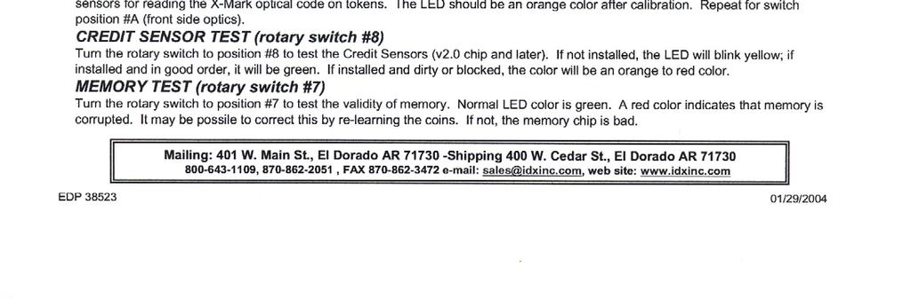
18 Bar Graph Service Indicator TM Perma-Scroll allows the operator to have his own custom sales messages and instructions. Your customer can easily switch between Super vac, Turbo Vac, and Spot Remover. A computer-controlled timer adjusts the remaining time of service being used. Internally lit dome advertises around the clock Lit instructions encourages night sales Easy-to-Understand instructions. Internally locked strong box coin vault Built in coin counter activated by hand-held unit Timer and LED display unit provide visual and beeper warning messages when time is expired and asks your customer if more time is needed Here s How It Works Until your customer drops coins, and LED display scrolls the message below : When the vac starts, the LED bargraph displays a countdown of remaining service. (see example below: 50% remaining service) Or your own custom message: (see example below) After your customer s time expires, the X-TRA TIME message scrolls for 20 seconds encouraging an additional purchase without having to restart at the full price. (see example below) After the X-TRA TIME message expires, an exit message scrolls. (see example below) PAGE 18

19 Coin/Bill Counter PAGE 19
 indicates that")
 disarms Alarm, after Alarm has been triggered.")
20 Burglar Alarm (optional, D-1 Models Only) Alarm LED Indicators Constant Green Standby Mode Flashing Red Alarm Set Fast Flashing Red & Green Alarm Activated and Battery Back Up Supports Alarm *Approximate actuation distance 24 Keyfob Idle Mode (Button 1) indicates that Alarm is ON but disengaged. Set Mode (Button 2) indicates Alarm in Alert state. Reset Mode (Button 3) disarms Alarm, after Alarm has been triggered. Battery Shipped in separate box Molex Plug for easy installation Unit is equipped with automatic battery charger PAGE 20


21 Microcoin QL Instruction Page PAGE 21


22 MA 820 Instruction Page PAGE 22


23 MA 820 Instruction Page PAGE 23
24 Notes PURCHASE DATE: SERIAL #:
PowerVac Model Installation & Owner s Guide
 PowerVac Model 0000 Installation & Owner s Guide CAUTION: Read the instructions before using the appliance! www.ivs-vacuum.com 800.968.87 0000 Table of Contents IMPORTANT SAFETY INSTRUCTIONS Limited Warranty
OWNER S MANUAL. CAUTION: Read the instructions before using the appliance!
 OWNER S MANUAL CAUTION: Read the instructions before using the appliance! PART #INST-510003 1 TABLE OF CONTENTS Safety Instructions...2 Limited Warranty...3 Typical Installation and Proper Placement...4
Model Parts Guide. CAUTION: Read the instructions before using the appliance!
 Model 0000 s Guide CAUTION: Read the instructions before using the appliance! 000 Table of Contents Limited Warranty... s Guide... s Sheet - Vac s... s Sheet - Cabinet Top Doors... s Sheet - Mechanical...
J.E. ADAMS INDUSTRIES OWNERS MANUAL VACUUMS AIR/VACUUMS AIR/WATER/VACUUMS
 J.E. ADAMS INDUSTRIES OWNERS MANUAL AIR/ AIR/WATER/ PAGE 1-3 SPECIFICATIONS PAGE 4-6 INSTALLATION PAGE 7-10 WIRE DIAGRAMS PAGE 11 TIMER INFORMATION PAGE 12-16 DRAWINGS & PART NUMBERS PAGE 17 TROUBLESHOOTING
BAD BOY GRASS BAGGING SYSTEM
 BAD BOY GRASS BAGGING SYSTEM TABLE OF CONTENTS WILL FIT ALL 2019 OUTLAW SERIES MOWERS SAFETY RULES AND INFORMATION.. 2 GENERAL OPERATION.... 3 WARRANTY INFORMATION.... 5 INSTALLATION INSTRUCTIONS.. 6 PAGE
Models- 8105, Commercial Vacuums. Product Information Product Dimensions. Important Safety Instructions
 Models- 8105, 9225 9235 Commercial Vacuums Page 2 Page 3 Page 4 Page 5 Page 5-8 Page 9 Page 10 Page 10 Page 11 Page 12-19 Page 20-24 Product Information Product Dimensions Specifications Important Safety
CTFRP Series Power Supplies
 CTFRP Series Power Supplies Ferroresonant Non-Standby Power Supplies User Manual Myers Power Products 6/2013 CTFRP Series Manual Chapter 1 General Information The Myers CTFRP Series Power Supply provides
Installation and Operation Guide
 Bus-Scan 500 RF Installation and Operation Guide All Content and Information are Copyright 2018-2019 Robotics Technologies, Inc. Features and Information are subject to change without notice. All Rights
Motorized Stainless 2-Way Valves
 Installation and Operation Manual Motorized Stainless 2-Way Valves Safety Valve ETV Applications WARNING This Heat-Timer valve is strictly an operating valve; it should never be used as a primary limit
Operator's Manual. Storage System. Ultrasound Probe Cabinet. Manufactured by:
 Storage System Ultrasound Probe Cabinet Operator's Manual Manufactured by: CIVCO Medical Solutions 102 First Street South Kalona, IA 52247 USA 319.248.6757 / 800.445.6741 WWW.CIVCO.COM Copyright 2018 All
Part Number Mini Linear Lift Assembly Installation & Operator s Instruction Manual
 Part Number 39644 Mini Linear Lift Assembly Installation & Operator s Instruction Manual April 1999 MV1505C Chore-Time Warranty Mini Linear Lift Assembly Manual Chore-Time Warranty Chore-Time Equipment
INSTRUCTION MANUAL. 12-Station HD Shop 12V Portable Battery Charger
 INSTRUCTION MANUAL 12-Station HD Shop 12V Portable Battery Charger IMPORTANT SAFETY INSTRUCTIONS 1. SAVE THESE INSTRUCTIONS This manual contains important safety and operating instructions for your HD
INSTALLATION & OWNER'S MANUAL
 INSTALLATION & OWNER'S MANUAL THE EAGLE POWER I BATTERY BACK UP PHONE (818) 764-6690 / TOLL FREE (800) 708-8848 PRE INSTALLATION INSTRUCTIONS BEFORE PROCEEDING WITH INSTALLATION READ THIS MANUAL THOROUGHLY
i n s t r u c t i o n m a n u a l
 i n s t r u c t i o n m a n u a l 8006 Six-Station AC Timer Residential/Light Commercial Independent Program Irrigation Controllers Installation, Programming and Operating Instructions Features Operates
READ AND SAVE THESE INSTRUCTIONS. ComfortBreeze UV360-1 SYSTEM 24V Ultra-Violet Air Cleaner. Trion
 READ AND SAVE THESE INSTRUCTIONS ComfortBreeze UV360-1 SYSTEM 24V Ultra-Violet Air Cleaner Trion www.trioniaq.com Installation, Operation, & Maintenance Manual 1. Warranty 2. Safety & Warnings ComfortBreeze
14", 18" & 24" Fiberglass Turbo Fans Installation & Operator s Instruction Manual
 14", 18" & 24" Fiberglass Turbo Fans Installation & Operator s Instruction Manual 09484:09#52
D Instructions/Parts. Siphon Feed Detail Spray Gun D
 Instructions/Parts D-5-55 Siphon Feed Detail Spray Gun FOR PRODUCT INFORMATION CALL: 1-800-742-7731 309991D Important Safety Instructions Read all warnings and instructions in this manual. Save these instructions.
LED LARGE WALL PACK (CUTOFF & STANDARD)
") General Safety Information To reduce the risk of death, personal injury or property damage from fire, electric shock, falling parts, cuts/abrasions, and other hazards read all warnings and instructions
General Safety Information To reduce the risk of death, personal injury or property damage from fire, electric shock, falling parts, cuts/abrasions, and other hazards read all warnings and instructions
OWNER S MANUAL SELF-PRIMING PORTABLE UTILITY PUMP
 Model 54011-0 OWNER S MANUAL SELF-PRIMING PORTABLE UTILITY PUMP Questions, problems, missing parts? Before returning to the store call AQUAPRO Customer Service 8 a.m. - 5 p.m., EST, Monday-Friday 1-844-242-2475
MGFHVLP. Instructions/Parts. Mini Gravity Feed System E. Part No Includes MGFHVLP Mini Gravity Feed Spray Gun and MGC 125 Gravity Cup.
 Instructions/Parts MGFHVLP Mini Gravity Feed System FOR PRODUCT INFORMATION CALL: 1-800-742-7731 309989E For gravity feed spraying of automotive colors and clears. Ideal for touch-up and detail work. Important
Installation & Operators Manual
 Installation & Operators Manual Model Serial Number Purchase Date 2007-2008 SegVator, LLC Patent Pending All Rights Reserved Important Safety Information Make sure the vehicle has a properly installed
Firstmate Installation Manual and User's Guide May, 2003
 Firstmate Installation Manual and User's Guide May, 2003 Aqualogic Marine, Inc. 506-D Terry Lane - Washington - Missouri - 63090 Warning No user serviceable parts are located inside your Firstmate unit.
Model LA 4400 Time Delay OFF Controller
 ISIMET LA Series Model LA 4400 Time Delay OFF Controller Installation, Operation and Maintenance Manual Application: The Time Delay OFF Controller with integral 24-hr. programmable time clock operates
ATD-5598 Self-Powered Inductive Clamp Timing Light
 ATD-5598 Self-Powered Inductive Clamp Timing Light The original battery powered timing light, built with quality to last. There's no need to connect to a 12V battery for power. Unit is powered by (2) D
LESTRONIC II BATTERY CHARGER MODEL 19740
 *01679* LESTRONIC II BATTERY CHARGER MODEL 19740 PLEASE SAVE THESE IMPORTANT SAFETY AND OPERATING INSTRUCTIONS For correct operation of the equipment, it is important to read and be familiar with this
Read this entire manual before operation begins.
 Read this entire manual before operation begins. Record below the following information which is located on the serial number data plate. Serial No. Model No. Date of Installation Contents Specifications.............
Read this entire manual before operation begins.
 Read this entire manual before operation begins. Record below the following information which is located on the serial number data plate. Serial No. Model No. Date of Installation Contents Specifications.............
DC to AC Power Inverters
 Manufacturer of Dimensions TM Inverters 4467 White Bear Parkway St. Paul, MN 55110 Phone: 651-653-7000 Fax: 651-653-7600 E-mail: inverterinfo@sensata.com Web: www.dimensions.sensata.com ISO 9001:2000 Certified
DC to AC Power Inverters
 Manufacturer of Dimensions TM Inverters 4467 White Bear Parkway St. Paul, MN 55110 Phone: 651-653-7000 Fax: 651-653-7600 E-mail: inverterinfo@sensata.com Web: www.dimensions.sensata.com 121114C OWNERS
LESTRONIC II BATTERY CHARGER BUILT-IN OR PORTABLE CHARGERS
 LESTRONIC II BATTERY CHARGER BUILT-IN OR PORTABLE CHARGERS PLEASE SAVE THESE IMPORTANT SAFETY AND OPERATING INSTRUCTIONS For correct operation of the equipment, it is important to read and be familiar
INSTALLATION/OWNER'S MANUAL DP " Woofer in Enclosure
 INSTALLATION/OWNER'S MANUAL DP1000 10" Woofer in Enclosure Installation Thank you for purchasing the DP1000 10" Woofer with enclosure. Although Dual has attempted to make sure all of the information contained
OWNER S MANUAL SUBMERSIBLE UTILITY PUMP
 Model 51101-0 OWNER S MANUAL SUBMERSIBLE UTILITY PUMP Questions, problems, missing parts? Before returning to the store call AQUAPRO Customer Service 8 a.m. - 5 p.m., EST, Monday-Friday 1-844-242-2475
Operator s Manual. Automatic Electric Jack Leveling. The leveling system shall only be operated under the following conditions:
 Operator s Manual with Automatic Leveling Touchpad #140-1226 Control Box #140-1224 co Copyright PowerGear 1/07 #82-L0368 Rev. 0D Contents Before You Level Your Coach 1 Caution 1 Leveling System Operating
SYSTEM CONTROL KIT. Model: CK-41F. Designed for use with the SWG Series Power Venter for controlling Natural Gas or L.P. Gas appliances.
 SYSTEM CONTROL KIT Model: CK-41F Designed for use with the SWG Series Power Venter for controlling Natural Gas or L.P. Gas appliances. ITEMS INCLUDED IN KIT: 1- Junction box with mounted pressure switch
Level One Electric Vehicle Charging Station FREE STANDING Product Guide
 Level One Electric Vehicle Charging Station FREE STANDING Product Guide Model # SC2-120 Shorepower Technologies 2351 NW York St. Portland, OR 98664 503-892-7345 info@shorepower.com www.shorepower.com 2
OPW Installation and Maintenance Instructions OPW Series Primary and Secondary Bucket Replacement Instructions
 OPW Installation and Maintenance Instructions OPW 1-3100 Series Primary and Secondary Bucket Replacement Instructions IMPORTANT: Please read these warnings and follow the assembly instructions completely
Model LA 4100 Time Delay OFF Controller
 ISIMET LA Series Model LA 4100 Time Delay OFF Controller Installation, Operation and Maintenance Manual Application: The Time Delay OFF Controller operates as a single output controller where the application
MaxLite LED UTILITY WRAP FIXTURES
 General Safety Information To reduce the risk of death, personal injury or property damage from fire, electric shock, falling parts, cuts/abrasions, and other hazards read all warnings and instructions
Linear Actuator. Installation Manual. warranty installation parts list. Linear Actuator Installation Manual Page 1
 Linear Actuator Installation Manual warranty installation parts list January 2004 Linear Actuator Installation Manual Page 1 MA1221B12 Warranty Information Chore-Time Equipment ( Chore-Time ) warrants
ELECTRONIC FIREPLACE DAMPER
 ELECTRONIC FIREPLACE DAMPER Model: FSE Low Profile Series The Flue Sentinel Electronic Fireplace Damper is designed to increase the comfort and energy efficiency of residential homes with gas-fired fireplaces.
Description of the Power Nozzle Accessory Kit 4
 Contents IMPORTANT SAFETY INSTRUCTIONS 2 Polarization Instructions 3 Description of the Power Nozzle Accessory Kit 4 Operating the Power Nozzle & Accessories 5 Inserting the hose Turning on the power nozzle
Installation Instructions
 Installation Instructions AMP RESEARCH Power Step by Bestop Automatic Retracting Running Board Vehicle Application Nissan Titan King Cab 2004 and newer (5 ft.) Part Number: 75106-01 Nissan Titan Crew Cab
JETPAC SERIES VACS 1 Re v B
 JETPAC SERIES VACS 1 TABLE OF CONTENTS Product Information.. 3 Specifications.. 4 Installation Timer Setup o Requirements..5 o Vac Installation. 6 o Footprint and Dimensions 7 SSAC Setup 8 Timer Settings
IMPORTANT SAFETY INFORMATION
 Specifications Outer Dimensions Inner Dimensions Lockbox Inner Dimensions Panel Features Includes 21 W x 15 D x 59 H 20-1/2 W x 12 D x 49-1/2 H 20-1/2 W x 11 D x 7-5/8 H Dual Security System for Keyed
Air Curtain. Installation, Operating and Maintenance Instructions
 Installation, Operating and Maintenance Instructions Save this manual for future reference. Air Curtain Model Numbers: ES026, ES036, ES042, ES048, ES060, ES072 READ THIS OWNER S MANUAL CAREFULLY BEFORE
Countertop B.I.B. Butter Dispenser Instruction Manual Model #2496
 Part No. 39177 Countertop B.I.B. Butter Dispenser Instruction Manual Cincinnati, OH 45241-4807 USA SAFETY PRECAUTIONS Installation Instructions Countertop B.I.B. Checking Shipment Unpack all cartons and
Installation and Operation Instructions Safety Director Arrow
 Installation and Operation Instructions Safety Director Arrow! WARNING! Failure to install or use this product according to manufacturers recommendations may result in property damage, serious bodily/personal
Dimensions 12/800N 12/1200N D. DC to AC Power Inverters. OWNERS MANUAL for Models: OWNERS MANUAL April ISO 9001:2000 Certified Company
 Manufacturer of Dimensions Inverters 4467 White Bear Parkway St. Paul, MN 55110 Phone: 651-653-7000 Fax: 651-653-7600 E-mail: inverterinfo@sensata.com Web: www.dimensions.sensata.com OWNERS MANUAL April
Hazardous Location Direct-Drive Exhaust Fans. Operating Instructions & Parts Manual
 Operating Instructions & Parts Manual EN Hazardous Location Direct-Drive Exhaust Fans Models 10D996 thru 10D999, 10E001 thru 10E007, 10E009 thru 10E020, 32ZN53 and 32ZN54 474904 PLEASE READ AND SAVE THESE
Condensate Pump. Installation and Safety Instructions CP-22 CP CP-22LP CP-22LP-230
 Condensate Pump Installation and Safety Instructions CP-22 CP-22-230 CP-22LP CP-22LP-230 CP-22 CP-22LP CP-22T CP-22LPT CP-22-230 CP-22LP-230 CP-22T-230 CP-22LPT-230 Rated Voltage 120 Volts / 60 Hz 220
Instructions 3A4793B EN. See page 3 for a complete list of model descriptions and part numbers.
 Instructions Variable Frequency Drives 3A4793B EN Variable frequency drives (VFDs) to power and control electric motor driven agitators. For professional use only. Not approved for use in explosive atmospheres
Condensate Pump. Installation and Safety Instructions CP-22 CP CP-22LP CP-22LP-230
 Condensate Pump Installation and Safety Instructions CP-22 CP-22-230 CP-22LP CP-22LP-230 CP-22 CP-22LP CP-22T CP-22LPT CP-22-230 CP-22LP-230 CP-22T-230 CP-22LPT-230 Rated Voltage 120 Volts / 60 Hz 220
OWNERS MANUAL JANUARY 2007 ISO
 Manufacturer of Dimensions TM Inverters 4467 White Bear Parkway St. Paul, MN 55110 Phone: 651-653-7000 Fax: 651-653-7600 E-mail: inverterinfo@sensata.com Web: www.dimensions.sensata.com 121231B OWNERS
MIL-24/2600Q MIL-24/3200DQ
 Manufacturer of Dimensions TM Inverters 4467 White Bear Parkway St. Paul, MN 55110 Phone: 651-653-7000 Fax: 651-653-7600 E-mail: inverterinfo@sensata.com Web: www.dimensions.sensata.com 121473B OWNER'S
24 VOLT AUTOMATIC BATTERY CHARGER PART NO
 24 VOLT AUTOMATIC BATTERY CHARGER PART NO. 957732 AC Input: DC Output: Battery Type: Specifications 230 volts, 50 hertz, 3.5 amps, single-phase 24 volts, 20 amps initially tapering to 6 amps 24 volt, 12
AC Irrigation and Propagation Controllers I Four Station, 5006-I and 5006-IP Six Station
 AC Irrigation and Propagation Controllers 5004-I Four Station, 5006-I and 5006-IP Six Station I N S T R U C T I O N M A N U A L Table of contents Introduction 1 1. Specifications 1 2. Controller Mounting
Read this entire manual before operation begins.
 Read this entire manual before operation begins. Record below the following information which is located on the serial number data plate. Serial No. Model No. Date of Installation Contents Specifications.............
SUBMERSIBLE SUMP PUMPS
 SUBMERSIBLE SUMP PUMPS Zoeller is a registered trademark of Zoeller Co. All Rights Reserved. MODEL #1099-0001 Español p. 11 ATTACH YOUR RECEIPT HERE Serial Number Purchase Date Questions, problems, missing
Extension Hopper Installation & Operator s Instruction Manual for Model 55, 75, 90, & HMC FLEX-AUGER Feed Delivery Systems
 Extension Hopper Installation & Operator s Instruction Manual for Model 55, 75, 90, & HMC FLEX-AUGER Feed Delivery Systems April 02 Chore-Time Warranty Chore-Time Equipment warrants each new product manufactured
Prime Attachments & Custom Fab Brush Mower Owners/Operators Manual
 Prime Attachments & Custom Fab Brush Mower Owners/Operators Manual The operator is responsible for the safe operation and maintenance of the machine. It is important that anyone who uses the machine is
OWNERS MANUAL JANUARY 2007 ISO
 Manufacturer of Dimensions TM Inverters 4467 White Bear Parkway St. Paul, MN 55110 Phone: 651-653-7000 Fax: 651-653-7600 E-mail: inverterinfo@sensata.com Web: www.dimensions.sensata.com OWNERS MANUAL JANUARY
# and # FAST Fuel System Kits
 1 INSTRUCTIONS #307500 and #307501 Fuel System Kits Thank you for choosing products; we are proud to be your manufacturer of choice. Please read this instruction sheet carefully before beginning the installation.
ATD Gallon Pressurized Oil Drain Owner s Manual
 ATD-5203 30 Gallon Pressurized Oil Drain Owner s Manual TECHNICAL SPECIFICATIONS Model: ATD-5203 Capacity: 30 Gallon Drain Funnel Working Height: 47.25 to 70.5 Drain Funnel Diameter: 15.75 Plastic Tray:
Read this entire manual before operation begins.
 Read this entire manual before operation begins. Record below the following information which is located on the serial number data plate. Serial No. Model No. Date of Installation Contents Specifications.............
Read this entire manual before operation begins.
 Read this entire manual before operation begins. Record below the following information which is located on the serial number data plate. Serial No. Model No. Date of Installation Contents Specifications.............
CAPACITOR ACTUATED PORTABLE STARTER CAPS USER GUIDE. INST048 Doc 3.01
 CAPACITOR ACTUATED PORTABLE STARTER CAPS USER GUIDE INST048 Doc 3.01 CONTENTS General Information...2 Charts...3 Before First Use...4 Safety Requirements...5 What to Expect from the CAPS...5 CAPS Diagram...6
T1-Titanium Non-HVLP Spray Gun
 T1-Titanium Non-HVLP Spray Gun THE SPRAY GUN PEOPLE FOR PRODUCT INFORMATION CALL: 1-800-742-7731 Important Safety Instructions Read all warnings and instructions in this manual. Save these instructions.
Installation and Operation Guide
 Bus-Scan CR2 RF Installation and Operation Guide All Content and Information are Copyright 2018 Robotics Technologies, Inc. Features and Information are subject to change without notice. All Rights Reserved.
PRYCO, INC. P. O. BOX 108 Mechanicsburg, IL OPERATIONS AND MAINTENANCE MANUAL For PUMP SETS
 PRYCO, INC. P. O. BOX 108 Mechanicsburg, IL 62545 Telephone: 217 / 364-4467 Fax: 217 / 364-4494 OPERATIONS AND MAINTENANCE MANUAL For PUMP SETS WHAT TO DO FIRST Upon receiving your new pump set system
36 VOLT AUTOMATIC BATTERY CHARGER PART NO
 36 VOLT AUTOMATIC BATTERY CHARGER PART NO. 957727 AC Supply: DC Output: Battery Type: Specifications 120 volts, 60 Hertz, 10 amps, single-phase 36 volts, 20 amps initially tapering to 6 amps 36 volt, 18
Installation Power Management Unit Battery Cables and Battery Harness
 Installation Power Management Unit Battery Cables and Battery Harness Important Safety Messages SAVE THESE INSTRUCTIONS - This manual contains important instructions that should be followed during installation
Operating Instructions
 Operating Instructions PRO- If you sell, inventory or service lead-acid batteries, you want the battery you take off the shelf to be as new as the day it was manufactured. However, batteries that sit idle
Laboratory Series. Ultraviolet Ozone Destruct System Installation, Operation and Maintenance Manual. One Source for All Your UV Needs!
 Laboratory Series Ultraviolet Ozone Destruct System Installation, Operation and Maintenance Manual KEEP THIS MANUAL ON HAND IT IS IMPORTANT THAT THOSE RESPONSIBLE FOR THE INSTALLATION OF THIS EQUIPMENT,
AUTOMATIC BURNISHER MODEL FURY 21 HSB
 AUTOMATIC BURNISHER MODEL FURY 21 HSB INTRODUCTION OPERATING & MAINTENANCE INSTRUCTIONS This operator s book has important information for the use and safe operation of this machine. Read this book carefully
Model LA 4300 Time Delay OFF Controller
 ISIMET LA Series Model LA 4300 Time Delay OFF Controller Installation, Operation and Maintenance Manual Application: The Time Delay OFF Controller operates as a single output controller where the application
AEROMOTIVE Part # INSTALLATION INSTRUCTIONS
 AEROMOTIVE Part # 16302 INSTALLATION INSTRUCTIONS CAUTION: Installation of this product requires detailed knowledge of automotive systems and repair procedures. We recommend that this installation be carried
SOLO VACUUM OPERATING & MAINTENANCE
 SOLO VACUUM INTRODUCTION OPERATING & MAINTENANCE INSTRUCTIONS This operator s book has important information for the use and safe operation of this machine. Read this book carefully before starting the
The Ultimate Smart Grid Solution INSTRUCTION MANUAL
 ECOWISE EW30/1 The Ultimate Smart Grid Solution INSTRUCTION MANUAL Welcome! Congratulations on selecting the ECOWISE unit to manage your energy supply needs. ECOWISE units reduce the amount of electric
Sprinter Van A
 I N S T A L L A T I O N G U I D E APPLICATION MODEL YR PART # Sprinter Van 2007-2016 75163-01A INSTALLATION TIME 3-5 Hours Professional installation recommended SKILL LEVEL 1 2 3 4 4= Experienced TOOLS
Installation Instructions: Bumper (Part # SB76854) XJ Jeep Cherokee XRC Body Armor 4-Door
 XJ Jeep Cherokee XRC Body Armor 4-Door") NOTE: Carefully read entire instructions thoroughly before attempting to install this part. Parts Included Qty 93-7818 XRC Front Fender Skin: Drvr 1 93-7862 XRC Front Door Skin: Drvr 1 93-7863 XRC Rear
NOTE: Carefully read entire instructions thoroughly before attempting to install this part. Parts Included Qty 93-7818 XRC Front Fender Skin: Drvr 1 93-7862 XRC Front Door Skin: Drvr 1 93-7863 XRC Rear
VICE MOUNTED BEAD ROLLER
 VICE MOUNTED BEAD ROLLER Owner s Manual WARNING: Read carefully and understand all ASSEMBLY AND OPERATION INSTRUCTIONS before operating. Failure to follow the safety rules and other basic safety precautions
Model , Series A 9 in. (23 cm) roller frame with 45 angle and 12 in. reach 1/2 in. (13 mm) nap roller cover
 roller frame with 45 angle and 12 in. reach 1/2 in. (13 mm) nap roller cover") Operating Instructions 309899 Rev. A This manual contains important warnings and information. READ AND KEEP FOR REFERENCE. INSTRUCTIONS Manufactured by Model 246818, Series A 9 in. (23 cm) roller frame
Operating Instructions 309899 Rev. A This manual contains important warnings and information. READ AND KEEP FOR REFERENCE. INSTRUCTIONS Manufactured by Model 246818, Series A 9 in. (23 cm) roller frame
ClipperCreek, Inc. Innovative Infrastructure for Electric and Hybrid Vehicles. User s Manual. Model ACS
 ClipperCreek, Inc. Innovative Infrastructure for Electric and Hybrid Vehicles User s Manual Model ACS PLEASE NOTE This user s manual includes the latest information at the time of printing. ClipperCreek,
TRAILER AUXILIARY POWER SYSTEM (TAPS) INSTALLATION GUIDE V1.10
 INSTALLATION GUIDE V1.10") TRAILER AUXILIARY POWER SYSTEM (TAPS) INSTALLATION GUIDE V1.10 TAPS INSTALLATION GUIDE V1.10 1 TRAILER AUXILIARY POWER SYSTEM CONTENTS General Information and System Logic... 2 Diagrams... 3 System Diagram
TRAILER AUXILIARY POWER SYSTEM (TAPS) INSTALLATION GUIDE V1.10 TAPS INSTALLATION GUIDE V1.10 1 TRAILER AUXILIARY POWER SYSTEM CONTENTS General Information and System Logic... 2 Diagrams... 3 System Diagram
4-SIDED BASKETBALL SCOREBOARD LED BAR DIGIT INSTRUCTION MANUAL REVISION DATE: PART#:
 4-SIDED BASKETBALL SCOREBOARD LED BAR DIGIT INSTRUCTION MANUAL REVISION DATE: 12-04-07 PART#: 98-0001-09 SERVICE & CUSTOMER INFORMATION CUSTOMER MUST HAVE PART NUMBER WHEN ORDERING ITEMS THROUGH THE SERVICE
37SCENE 46SCENE 79SCENE
 Installation and Operation Instructions LED SCENE LIGHT LED SCENE LIGHT 37SCENE 46SCENE 79SCENE 37SCENE 46SCENE Introduction The 37SCENE, 46SCENE, 79SCENE LED Scene Lights are designed for the emergency
MODEL L/R/EF Sectional Tire Spreader
 MODEL L/R/EF Sectional Tire Spreader Installation, Operation & Repair Parts Information Branick Industries, Inc. 4245 Main Avenue P.O. Box 1937 Fargo, North Dakota 58103 REV08032016 P/N: 81-0195E TABLE
Installation and Service Manual for SRC25, SRC252, SRC50, SRC502, SRC75, SRC752
 Rocking Piston Compressors Installation and Service Manual for SRC25, SRC252, SRC50, SRC502, SRC75, SRC752 Thank you for purchasing the Stratus SRC series rocking piston compressor. This instruction manual
INSTALLATION GUIDE. AMP RESEARCH TECH SUPPORT (Press 2) Monday - Friday, 6:00 AM - 5:00 PM PST
 Monday - Friday, 6:00 AM - 5:00 PM PST") INSTALLATION GUIDE APPLICATION AMP Part # Jeep Wrangler Unlimited (JK) 2007 2015 75122-01A (-Door Only) INSTALLATION TIME 3-5 Hours Professional installation recommended SKILL LEVEL 1 2 3 = Experienced
INSTALLATION GUIDE APPLICATION AMP Part # Jeep Wrangler Unlimited (JK) 2007 2015 75122-01A (-Door Only) INSTALLATION TIME 3-5 Hours Professional installation recommended SKILL LEVEL 1 2 3 = Experienced
model ps600 Address all communications and shipments to: FEDERAL SIGNAL CORPORATION
 MODEL: PS600 HZ: 60 A model ps600 installation and service manual for federal model ps600 FEDERAL SIGNAL CORPORATION POWER SUPPLY VOLTS: SERIES: 120VAC FEDERAL SIGNAL CORPORATION UNIVERSITY PARK, IL. U.S.A.
Effective June 1, 2013 This guide supersedes all previous versions
 Effective June 1, 2013 This guide supersedes all previous versions 3842 Redman Drive 1-800-797-7974 Fort Collins, CO 80524 www.commandlight.com L-CAS THANK YOU Please allow us to express a simple thank
APOLLO Gate Operators, Inc.
 APOLLO Gate Operators, Inc. Model BA12 12 VOLT DC BARRIER ARM OPERATOR INSTALLATION MANUAL 0707 CONTENTS IMPORTANT SAFETY INSTRUCTIONS... 3 Applications... 4 Pre-Installation Checklist... 5 Operator Installation...
Benron Equipment & supply, Inc.
 Benron Equipment & supply, Inc. Service Manual G5 Part Number 6-00A. and 6-00M Edition 0/008 Ez-Tex G5 Operational Instructions. Before attempting to use the G5 check material manufacturer for mixing and
INFINITY-1 HALOGEN LIGHT BAR INSTALLATION MANUAL 7000 SERIES
 INFINITY-1 HALOGEN LIGHT BAR INSTALLATION MANUAL 7000 SERIES Your purchase of a Wolo warning light is the perfect choice to compliment your vehicle. Wolo s warning lights are manufactured with the finest
I N S T A L L A T I O N G U I D E
 I N S T A L L A T I O N G U I D E APPLICATION AMP Part # Ford Super Duty - Crew Cab 2008-2010, 2013-2015 77134-01A Note:The application works only on the Crew Cab model Vehicles. INSTALLATION TIME 3-5
INFINITY-3 STROBE LED BAR INSTALLATION MANUAL 7700 SERIES
 INFINITY-3 STROBE LED BAR INSTALLATION MANUAL 7700 SERIES Your purchase of a Wolo warning light is the perfect choice to compliment your vehicle. Wolo s warning lights are manufactured with the finest
2-Pack Indoor Simulated Dome Security Cameras
 2-Pack Indoor Simulated Dome Security Cameras Owner s Manual WARNING: Read carefully and understand all ASSEMBLY AND OPERATION INSTRUCTIONS before operating. Failure to follow the safety rules and other
Spray Nozzle Adapters
 INSTRUCTIONS-PARTS LIST 306 788 INSTRUCTIONS This manual contains important warnings and information. READ AND KEEP FOR REFERENCE. First choice when quality counts. Rev. G Supersedes Rev. F DIRECTIONAL
4" ENVIRONMENTAL E-SERIES PUMPS OWNER'S MANUAL. DANGER warns about hazards that will cause. WARNING warns about hazards that can cause
 4" ENVIRONMENTAL E-SERIES PUMPS OWNER'S MANUAL BEFORE INSTALLING PUMP, BE SURE TO READ THIS OWNER S MANUAL CAREFULLY. CAUTION Fill pump with water before starting or pump will be damaged. The motor on
CRD600 Automatic Fitting Inserter
 CRD600 Automatic Fitting Inserter OPERATIONS MANUAL VERSION 2.3 LAST EDITED 12.07.2018 cleanroomdevices.com 1 Table of Contents Title Page.. 1 Table of Contents. 2 1.0 General Product & Safety Information...3