Operating and Maintenance Manual APCU Series All Purpose Container Unloader
|
|
|
- Jordan Stevenson
- 5 years ago
- Views:
Transcription

1 Operating and Maintenance Manual APCU Series All Purpose Container Unloader Model #: APCU Serial # Placed in Service Southworth Products Corp P.O. Box 1380 Portland, ME Telephone: Fax: December 2018
2 This label (part # ) is required by California law. For more information visit This label (part # ) is required by California law. For more information visit 2 APCU Owner s Manual
3 CONTENTS INTRODUCTION... 4 RESPONSIBILITY OF OWNERS AND USERS... 5 SAFETY ALERT SYMBOLS AND SIGNAL WORDS... 6 SAFETY... 7 Safety devices... 8 INSTALLATION INSTRUCTIONS Preparation Positioning the lift Hydraulic connections Testing Electrical connections Checking the hydraulic system OPERATOR CONTROLS OPERATING INSTRUCTIONS OPTIONAL APCU SUPPORT STANDS MAINTENANCE Hazards Servicing the unit safely Routine maintenance-weekly Routine maintenance-monthly Routine maintenance - 6 months or 500 hours TROUBLESHOOTING Troubleshooting Table ADJUSTMENT & REPLACEMENT PROCEDURES Aligning the photo eyes About the proximity switches Setting end of travel for tilt down function Setting end of travel for tilt up function Setting end of travel for dump up function Setting end of travel for dump down function Inspecting and cleaning a control valve Removing a cylinder Repacking a cylinder Replacing a cylinder ORDERING REPLACEMENT PARTS WARRANTY List of Figures and Tables Fig. 1 Overall View - Load Enclosure Lowered... 8 Fig. 2A Operating Sequence - Loading Position... 9 Fig. 2B Operating Sequence - Tilt 90 degree Position... 9 Fig. 2C Operating Sequence - Dump Position Fig. 3A-G Label diagrams and positions Fig. 3H APCU Support Stand Procedure Fig. 4 Control panel Fig. 5A Using the retainer bar Fig. 5B Proper retaining Table 1 Hydraulic Oil Specifications Fig. 6 Repacking the cylinder Fig. 7 Hydraulic schematic Fig. 8 Wiring Diagram Fig. 9 DC Power Supply Kit Fig. 10 APCU Program Ladder Logic Fig. 10A-C Hydraulic power unit APCU Owner s Manual 3
4 Introduction The Southworth All-Purpose Container Unloader (APCU) is designed to unload containers and pallets. APCU units are designed for tilting and dumping of equipment and materials in a general indoor industrial setting. This manual contains instructions on the safe and proper installation, use, and maintenance of the All Purpose Container Unloader unit. Be sure that this manual is available to the people who install, use, or service the unit. Be sure that all personnel read this manual before they install, use, or service the unit. The instructions in this manual are not necessarily all-inclusive, as Southworth cannot anticipate all conceivable or unique situations. In the interest of safety, please read this whole manual carefully. Please understand the material in this manual before you install, use, or service the APCU unit. If you have any questions about any of the instructions in this manual, please contact Southworth Products Corp. Southworth s product warranty is shown on the rear cover of this manual. This instruction manual is not intended to be or to create any other warranty, express or implied, including any implied warranty of merchantability or fitness for a particular purpose, all of which are hereby expressly excluded. As set forth more specifically in the product warranty, Southworth s obligation under that warranty is limited to the repair or replacement of defective components, which shall be the buyer s sole remedy, and Southworth shall not be liable for any loss, injury, or damage to persons or property, nor for any direct, indirect, or consequential damage of any kind resulting from the APCU unit. This manual is intended for stand alone APCU machines shipped about May 2015, and after with control panels supplied Southworth Products. Please contact Southworth Products for information about APCU machines shipped before May 2015 or machines with control panels, control and hydraulic schematics, PLC logic, or other differences that do not match those shown in this manual. 4 APCU Owner s Manual
5 Responsibility of Owners and Users Inspection and Maintenance The device shall be inspected and maintained in proper working order in accordance with Southworth s owner s manual. Removal from Service Any device not in safe operating condition such as, but not limited to, excessive leakage, missing rollers, pins, or fasteners, any bent or cracked structural members, cut or frayed electric, hydraulic, or pneumatic lines, damaged or malfunctioning controls or safety devices, etc. shall be removed from service until it is repaired to the original manufacturer s standards. Deflection It is the responsibility of the user/purchaser to advise the manufacturer where deflection may be critical to the application. Repairs All repairs shall be made by qualified personnel in conformance with Southworth s instructions. Operators Only trained personnel and authorized personnel shall be permitted to operate the lift. Before Operation Before using the device, the operator shall have: Read and/or had explained, and understood, the manufacturer s operating instructions and safety rules. Inspected the device for proper operation and condition. Any suspect item shall be carefully examined and a determination made by a qualified person as to whether it constitutes a hazard. All items not in conformance with Southworth s specification shall be corrected before further use of the equipment. During Operation The device shall only be used in accordance with this owner s manual. Do not overload. Ensure that all safety devices are operational and in place. Modifications or Alterations Modifications or alterations to any Southworth industrial positioning equipment shall be made only with written permission from Southworth. APCU Owner s Manual 5

6 SAFETY ALERT SYMBOLS AND SIGNAL WORDS The safety of all persons operating, maintaining, repairing, or in the vicinity of this equipment is of paramount concern. This is a powerful machine with moving parts, and is capable of causing personal injury if proper precautions are not taken. Therefore, throughout this manual, certain hazards have been identified which may occur in the use of the machine, and there are appropriate instructions or precautions which should be taken to avoid these hazards. In some cases, there are consequences which may occur if instructions or precautions are not followed. Below are the symbols and signal words along with their definitions referenced from ANSI Z Product Safety Signs and Labels Safety Alert Symbols: A symbol that indicates a hazard. It is composed of an equilateral triangle surrounding an exclamation mark. The safety alert symbol is only used on hazard alerting signs. It is not used on safety notice and safety instructions signs. A): for use with DANGER signal word; (safety white triangle, safety red exclamation mark, safety red background) B): for use with WARNING signal word; (safety black triangle, safety orange exclamation mark) C): for use with CAUTION signal word; (safety black triangle, safety yellow exclamation mark) D) and E): for use with DANGER, WARNING, or CAUTION signal word; (D: is a safety yellow triangle with a black border and safety black exclamation mark; E: is a safety yellow triangle with a safety black exclamation mark and a safety yellow border around a safety black band) NOTE: D and E are provided to allow for consistency with certain ISO standards such as ISO and ISO Signal Words: The words used in the signal word panel. The signal words for hazard alerting signs are DANGER, WARNING, and CAUTION. Safety notice signs use the signal word NOTICE. Safety instruction signs use signal words that are specific to the situation. DANGER indicates a hazardous situation which, if not avoided, will result in death or serious injury. WARNING indicates a hazardous situation which, if not avoided, could result in death or serious injury. CAUTION indicates a hazardous situation which, if not avoided, could result in minor or moderate injury. NOTICE is used to address practices not related to physical injury. SAFETY INSTRUCTIONS (or equivalent) signs indicate specific safetyrelated instructions or procedures. NOTE: DANGER, WARNING or CAUTION should not be considered for property damage accidents unless personal injury risk appropriate to these levels is involved. 6 APCU Owner s Manual
7 Safety Southworth is concerned about the safety of everyone who operates, maintains, repairs, or works near the APCU unit. The unit is a powerful machine with moving parts, and is capable of causing personal injury if proper precautions are not taken. For this reason, throughout this manual, we have pointed out some of the hazards which may occur as you use the unit. We have also listed the instructions or precautions you should take to avoid these hazards. In some cases, we have also pointed out the consequences which may occur if you do not follow these instructions or precautions. We will use the following system to identify the severity of the hazards: DANGER! Immediate hazard which will result in severe personal injury or death. WARNING! Hazard or unsafe practice which could result in severe personal injury or death. CAUTION! Hazard or unsafe practice which could result in minor personal injury or property damage. Please read and follow this instruction manual, including all safety instructions and precautions, carefully and completely. APCU Owner s Manual 7
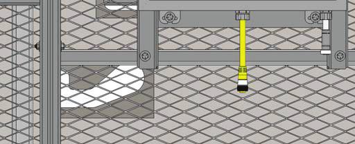
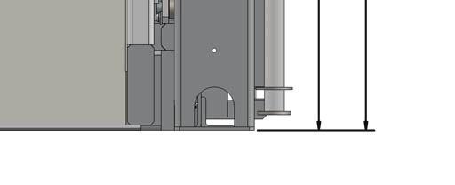
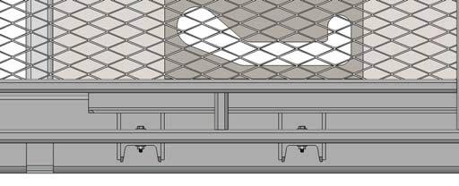
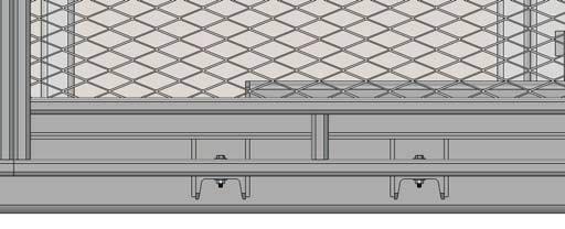
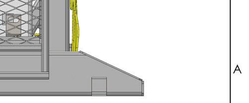
8 Safety Devices This unit has two kinds of safety devices. Guard fences protect each side of the unit. These are designed to keep everyone away from the moving parts of the unit while it is operating. These guards should always be in place when the unit is operating normally. There may be some cases where you will want to do maintenance work with the safety guards removed. You should be especially careful during these procedures. As the load enclosure moves up and down, pinch points are created where the moving parts meet. If you are standing too close to the load enclosure when it is moving, your arm or leg may be caught in the moving parts, and you may be hurt. Stay away from the pinch points when the safety guards are removed and the load enclosure is moving. Always replace the safety guards as soon as you are done with the maintenance work. The unit also includes three photo-eye systems. Each photo-eye system includes a light source on one side of the unit, and a reflector on the other side. If any of the light beams is broken, the unit will not start, and the load enclosure will not move. This helps to ensure that everyone is out of the way before the load enclosure moves. Before using the unit, please be sure that the guards are in place, and that the photo-eye system is working. If the guards are missing, or the photo-eyes are not working, turn off the machine right away and call a supervisor. Never operate the unit without these important safety features. Figure 3 shows the positions of the warning labels on the unit. These labels have been included for your safety. If you find that the labels are worn or missing, or have been painted over, ask Maintenance to replace the labels before you use the unit. Fig. 1 Overall View Safety photo-eyes Slots for retainer bar Wire mesh enclosure You should never operate the unit with the safety guards removed. This machine is equipped with an external power unit, which is mounted a short distance away from the machine. 8 APCU Owner s Manual
9 Fig. 2A Operating Sequence - Loading Position Fig. 2B Operating Sequence - Tilt 90 degree Position APCU Owner s Manual 9
 During the tilt part of the operating cycle, the load enclosure tilts up 90.")
 This manual contains information about the safe and proper installation, use, and maintenance of an APCU unit. Be sure that this manual is available to anyone who works with the unit.")

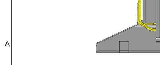
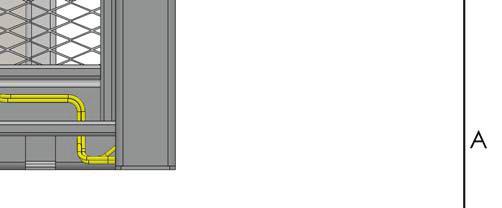
10 Figure 2 shows the operating sequence for the unit. At the start of the process, the operator places the pallet or container on the load enclosure. This enclosure is positioned at ground level, so it is easy to load the unit. (See Part A of the illustration.) During the tilt part of the operating cycle, the load enclosure tilts up 90. (See Part B.) Next, during the dump part of the cycle, the enclosure can be tilted an additional 50 to dump the items being loaded onto a conveyor or other device. (See Part C.) This manual contains information about the safe and proper installation, use, and maintenance of an APCU unit. Be sure that this manual is available to anyone who works with the unit. Be sure that everyone who uses the unit has read this manual. The instructions included in this manual are not necessarily all-inclusive, because Southworth cannot anticipate all conceivable or unique situations. In the interest of safety, please read this whole manual carefully. Please understand the material in this manual before you install, use, or service the APCU unit. If you have questions about any of the instructions in this manual, please contact Southworth Products Corp. Fig. 2C Operating Sequence - Dump Position 10 APCU Owner s Manual


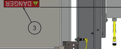


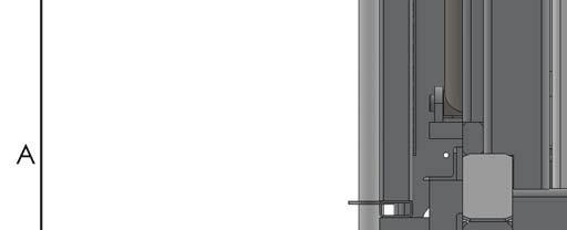
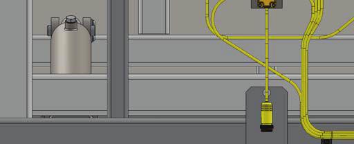

11 Fig. 3 - Label Diagrams and Positions APCU Owner s Manual 11


12 Fig. 3A - Label Diagrams and Positions APCU Owner s Manual 12


13 Fig. 3B - Label Diagrams and Positions APCU Owner s Manual 13


14 Fig. 3C - Label Diagrams and Positions APCU Owner s Manual 14


15 Fig. 3D - Label Diagrams and Positions APCU Owner s Manual 15


16 16 APCU Owner s Manual Fig. 3E - Label Diagrams and Positions


17 Fig. 3F - Label Diagrams and Positions APCU Owner s Manual 17


18 Fig. 3G - Label Diagrams and Positions "NOTICE" label p/n t 18 APCU Owner s Manual
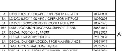
19 Fig. 3H STATUS: USE OF PROPRIETARY INFORMATION LIMITED TO WRITTEN AGREEMENT 063Z8 CAGE CODE DWG NO. PROJECT: IN INCHES TITLE MODEL C D T SHEET 4 OF 4 SIZE REV 1 FRACTIONS 1/ 8.XXX.005.XX.01 ANGLES:.5 UNLESS OTHERWISE SPECIFIED. DIMENSIONS ARE LABEL LOCATION DIAGRAM, SUPPORT STAND REF 3RD ANGLE PROJECTION P.O. Box 1380 Portland Maine LB WT SCALE 1:1 SOUTHWORTH PRODUCTS CORP. DR DATE A A TO RETURN APCU TO REGULAR SERVICE: 1. REMOVE LOCK OUT AND TURN ON THE MAIN POWER DISCONNECT ON THE APCU POWER CONTROL PANEL APCU SUPPORT STAND USE PROCEDURE DO NOT USE SUPPORT STANDS FOR HYDRAULIC, ELECTRICAL, MECHANICAL SERVICE OR MAINTENANCE. WHEN ENTERING THE MACHINE'S LOAD AREA FOR OTHER PURPOSES BOTH SUPPORT STANDS MUST BE USED. NOTICE: FAILURE TO FOLLOW THESE SPECIFIC USE PROCEDURES MAY SERIOUSLY DAMAGE THIS EQUIPMENT 1. USING THE CONTROL PUSHBUTTON, RAISE THE TILT FRAME TO THE HIGHEST POSITION. 2. TURN OFF AND LOCK OUT MAIN POWER DISCONNECT ON THE APCU POWER CONTROL PANEL. 3. NOTE: IF EQUIPPED WITH A GRACE VOLTAGE INDICATOR, ENSURE THAT NO LIGHTS ARE ILLUMINATED. SET THE SUPPORT STAND AT THE LOWEST EXTENSION HEIGHT PIN POSITION. NOTICE: BOTH SUPPORT STANDS MUST BE USED. NEVER HAVE ONLY ONE STAND UNDER TILT FRAME FOR SUPPORT. 4. POSITION EACH SUPPORT STAND IN THE LOAD AREA AS SHOWN IN DRAWING T, THE LOCATION IS IDENTIFIED BY THE ALIGNMENT LABEL ON THE INSIDE OF THE BASE FRAME RAIL. NOTE: IF NOT PRESENT, ATTACH LABEL T TO THE DIMENSIONS DETAILED IN DRAWING T THE AREA AROUND THE SUPPORT STANDS MUST BE FREE OF DEBRIS. NEVER HAVE ANYTHING UNDER THE SUPPORT STANDS WHEN THEY ARE IN USE. 5. AFTER PERSONNEL ARE CLEAR FROM LOAD AREA REMOVE LOCK OUT AND TURN ON THE SWITCH ON THE APCU POWER CONTROL PANEL. 6. USING THE CONTROL PUSHBUTTON, LOWER THE TILT FRAME UNTIL IT IS WITHIN 1/4" OF THE SUPPORT STAND B NOTICE: IF THE FRAME STARTS TO CONTACT THE SUPPORT STANDS THE MACHINE MOTION MUST BE STOPPED BY THE OPERATOR. DO NOT OVER POWER THE TILT FRAME ON TO THE SUPPORT STANDS. THIS MAY DAMAGE THE MACHINE AND MAY OVER STRESS THE FLOOR ANCHORS. TURN OFF AND LOCK OUT THE SWITCH ON THE APCU POWER CONTROL PANEL. IT IS NOW SAFE TO ACCESS THE LOAD AREA. USING THE CONTROL PUSHBUTTON RAISE THE TILT FRAME TO THE HIGHEST POSITION. TURN OFF AND LOCK OUT THE SWITCH ON THE APCU POWER CONTROL PANEL. REMOVE THE SUPPORT STANDS FROM THE LOAD AREA. 5. AFTER PERSONNEL ARE CLEAR FROM THE LOAD AREA REMOVE LOCK OUT AND TURN ON THE MAIN POWER DISCONNECT ON THE APCU POWER CONTROL PANEL. USING THE CONTROL PUSHBUTTON, LOWER THE LIFT FROM TO THE LOAD POSITION. B C C D D REVISIONS REV. ZONE DESCRIPTION DATE REVISED BY ECN # D UPDATED VIEWS 11/30/2017 KHS v T SHEET 4 OF 4 DWG NO. APCU Owner s Manual 19
20 Installation Instructions Preparation 1. Before you start to use the unit, check for local codes and ordinances which may apply. It is your responsibility to obtain any necessary permits. 2. Read all of these installation instructions carefully. Be sure to read and understand all of the warnings. 3. Select the location where the unit will be installed. Choose a location where the floor is firm, flat and level. As the unit operates, it is very important that the front edge (the load edge) of the load enclosure touches the floor at the same time as the rest of the bottom plate touches. CAUTION! If the middle or back edge of the bottom plate touches the floor before the front edge of the load enclosure, the machine may try to tip itself off the floor. This can happen if the floor surface is not flat. WARNING! If the unit is mounted on an unstable surface, it may tip over when in use. You may be hurt, and the unit and load may be damaged. Protect the unit from rain or moisture. If the electrical parts in the power unit get wet, workers may be hurt by electrical shock. The electrical parts may fail if they are wet. The electric motor on the remote power unit can create sparks. Do not install the power unit in an area where flammable gases may be present. 4. You will need these tools to install the unit: A lift truck that can lift the unit safely. Shims and appropriate lag bolts. A masonry drill and bit to drill the holes for the lag bolts. Extra hydraulic oil for flushing the hydraulic lines and refilling the tank. Level. Positioning the Lift 1. Remove the shipping material and unskid the unit. On the front of this manual, write down the model number, serial number, and date the unit is placed in service. You can find the model number and serial number on the name plate. 2. Move the unit into position, supporting the base of the unit. The base frame is fitted with eyes for the lag bolts. Drill the necessary holes and install the bolts. CAUTION! Do not hang the unit from the load enclosure. This can damage the unit. 3. Check the movement of the load enclosure through its full range. CAUTION! Take care not to create any pinch points. Hydraulic Connections 1. Install the power unit. Run the hydraulic line between the power unit and the APCU but do not make the connections yet. Be sure that the hydraulic line is protected from passing traffic, and that it will not be damaged. WARNING! Be sure that the hydraulic line will not be pinched by the unit as it raises or lowers. If you allow the line to be pinched, the unit may not work properly. A hose may break, the load enclosure may drop suddenly, and someone may be hurt. 2. Before connecting the power unit, blow out the hydraulic lines with compressed air. CAUTION! It is very important to keep the hydraulic oil free of dirt, dust, metal chips, water, and other contamination. Most of the problems with hydraulic systems are caused by contamination in the oil. Be sure all hydraulic lines are free of contamination before connecting them to the remote power unit. 20 APCU Owner s Manual
21 Testing 1. Clear the area around the unit. Remove any materials which might get in the way of the load enclosure as it raises or lowers. Be sure that the safety guards are in place on both sides of the unit. 2. Warn others to stay away from the unit. Operate the unit through its full range of travel. The load enclosure should rise smoothly with a quiet humming sound, and lower smoothly and quietly. Raise and lower the load enclosure a few times to check the operation. 3. As the load enclosure lowers, notice how the bottom of the enclosure meets the floor. The front edge (load edge) of the enclosure should touch at the same time as any other part of the enclosure. If any other part of the base of the load enclosure touches before the front edge, the floor is not flat. Insert shims above the low spots on the floor, so that the base is flat and level. WARNING! If another part of the load enclosure touches the floor before the front edge, the machine may not stop automatically at the correct moment. This may cause the machine to try to lift itself off of the floor. WARNING! If the Tilt Down proximity switch is out of adjustment, the machine may continue to run when it should be stopped. This may cause the machine to try to lift itself off of the floor. This could cause damage to the unit. 4. As a final step, clean up all spilled hydraulic fluid. Spilled hydraulic oil is slippery, and may present a fire hazard. If you clean up any spilled fluid, you will be able to tell right away if the unit begins to leak. Electrical Connections DANGER! This unit requires three-phase 460V AC. This voltage can kill you. Don t work with the electrical parts unless you are a qualified electrician. WARNING! The fuses or circuit breakers are designed to reduce any fire hazard. Be sure to install the fuses or circuit breakers. 1. Because the unit is designed for three-phase AC, you must be sure the pump motor is turning in the right direction. The load enclosure should start to move quickly when you press the up or down button. If the load enclosure does not move in 2 or 3 seconds, don t try to operate the unit! Exchange any two of the three-phase leads. If this does not correct the problem, see the troubleshooting instructions at the end of this manual. CAUTION! The power unit is designed for three-phase AC. If you connect the power so the motor runs backwards, the load enclosure will not move, and you may damage the pump. Do not operate the unit for more than 2 or 3 seconds if you think the motor might be turning backwards. Checking the Hydraulic System 1. Check the level of the hydraulic fluid in the system. With the load enclosure lowered completely, the hydraulic fluid can be checked by viewing the sight gauge on the reservoir of the power unit. Photo eyes and proximity switches may need occasional adjustments over time. See the Adjustments and Replacement Procedures section of this manual. APCU Owner s Manual 21

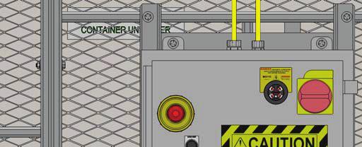
22 Operator Controls The control panel on the unit includes several standard controls. See Fig. 4. Main Disconnect Switch - This switch controls all electrical power to the unit. Fig. 4 Control Panel Tilt Up Button - When the operator presses this button, the unit tilts the load enclosure 90. See Part B of Fig. 2. Once the button is pressed, the machine will complete this part of the cycle - it is not necessary to hold the button. Dump Up Button - This button is used to unload the load enclosure. When the operator presses and holds the Dump Up button, the load enclosure begins to raise above the 90 tilt position. See Part C of Fig. 2. The load enclosure only moves when the operator is pressing the button. This allows the operator to move the load enclosure by small amounts to unload the load enclosure. (The Dump Up button will not operate until the load enclosure has reached the 90 tilt position.) Down Button - When the operator presses this button, the load enclosure lowers completely, back to the floor level. If the Dump Down button has been pressed, the unit begins by returning the load enclosure to the 90 tilt position. Next, the load enclosure lowers the rest of the way to the floor. Once the button is pressed, the machine will complete this part of the cycle - it is not necessary to hold the button. Emergency Stop Switch - In an emergency, the operator can press this button to stop the action of the load enclosure quickly. The unit will not operate again until the control system has been reset. If an E-stop is triggered, the E-stop reset button on the APCU control panel must be held down for 3 seconds to reset the system. If the system does not reset contact maintenance before proceeding any further. Safety Photo-Eyes (supplied) - This machine has three photo-eyes positioned near the front of the frame. See Fig. 1. They are designed to provide a signal to stop the unit if one of the beams is broken. Before the machine will operate again, the control system must be reset, indicating that both photoeyes are clear. Inspect the photo-eyes and verify their operation regularly. Operating Instructions 1. Before operating the unit, please read all of this section. If your unit has any optional modifications or accessories, information on these will be included at the end of the manual. DANGER! The unit requires three-phase 460 Volts AC. This voltage can kill you. Do not work with the electrical parts unless you are a qualified electrician. 2. Check the area around the APCU to be sure it is clean and clear of obstructions. Be sure that the load enclosure will be able to travel freely through its full range. 3. Load the enclosure correctly: Be sure that the load weighs no more than the maximum rated for the unit (3,000 lb.). Lower the load enclosure completely. Place the load as far back on the load enclosure as possible. Center the load in the sideto-side direction. 22 APCU Owner s Manual
23 As you load the load enclosure, you will break one or more of the 3 photo-eye beams at the front of the unit. See Fig. 1. As soon as you break any of the beams, the unit will be prevented from starting. When you are finished loading, the controls of the machine must be reset to return to a Ready condition. Be sure to back away from the front of the unit completely, so that the beams are not blocked. 4. As the load enclosure tilts, the top of the container or pallet will try to fall forward. See Fig. 5. To prevent this, you should install the retainer bar in the correct position on the unit. When you are loading the load enclosure, before it is tilted, the retainer bar should be set to hold the upper part of the container or pallet. (If the bar is set farther toward the back of the container or pallet, it may block some of the items as they fall free.) Notice that the bar will slide in the slots as the angle of the load enclosure changes. WARNING! Always place the retainer bar in the correct position before tilting the container or pallet. If you do not do this, the top of the container or pallet may fall forward. The items being loaded may be damaged. Never try to load the load enclosure while it is moving. 6. Operate the unit. Press the Tilt Up button. The load enclosure will tilt 90. (The machine will complete this part of the cycle by itself - it is not necessary to hold the button.) CAUTION! If the unit does not operate right away, turn off the unit and call a qualified maintenance worker. The next job is to dump the items being loaded onto the conveyor. To do this, press and hold the Dump Up button until the load enclosure dumps about half of the load. Once this has happened, press and hold Dump Up again to dump the rest of the load. (The Dump Up control will only operate while you are actually pressing it.) CAUTION! Avoid bumping the load enclosure into position by pressing the Dump Up control many times for short periods. This will cause the hydraulic equipment to wear much more quickly. 7. Once the load has been dumped, lower the load enclosure. Press the Down button. The load enclosure will lower to the Tilt 90 position, then lower the rest of the way to the floor. (Once you press the Down button, it is not necessary to hold it.) 5. Before operating, be sure everyone is clear of the unit. WARNING! Do not try to lift a load that exceeds the maximum rating. If you try this, the unit may fail suddenly. Someone may be hurt, and the unit and load may be damaged. Never allow anyone to ride on the load enclosure while its moving. This unit includes two important kinds of safety devices. The guard fences on the sides of the unit are designed to keep anyone from touching the moving parts of the unit while it is operating. The photo eyes at the front of the unit are designed to stop the unit if anyone is standing in the way. Do not operate the unit unless both kinds of safety devices are in position and are functional. APCU Owner s Manual 23

24 Note: Different containers utilize different retaining bar positions. Please keep this in mind as you load each container and make sure that the retaining bar is in the proper position to prevent injury or damage to equipment. The retaining bar should be placed in a position which is as close as possible to the rear of the container unloader. The retainer bar is placed above the rear edge of the container. The retainer bar holds the rear edge of the container. The retainer bar is placed above the rear edge of the pallet. The retainer bar holds the rear edge of the pallet. The pallet is placed as far back as possible. Fig. 5A Using the retainer bar 24 APCU Owner s Manual


25 Fig. 5B Proper Retaining - Using the retainer bar The Post Office supply s markings for containers and where the retaining bar should be used. These locations should be adhered to for retaining containers and skids. Examples of properly retained containers and skids: When you have BMC or OTR that are over load you will have to level them out before putting it into the unloaders. Do not put the top bar into the Postal Pak Position. APCU Owner s Manual 25
26 APCU with controls Operational Description Indicator Proximity Switches 1. Tilt Down (PRS2) 2. Tilt Up (PRS1) 3. Dump Down (PRS4) 4. Dump Up (PRS3) Load Area Retroreflective Photo-Eyes Quantity three Control Buttons 1. E-STOP -- lighted red, located on the control panel front 2. E-STOP RESET -- lighted green, located on the control panel front 3. GUARD RESET -- lighted amber, located on the control panel front 4. UP -- located on the control panel front and on remote pushbutton station 5. DOWN -- located on the control panel front and on remote pushbutton station 6. STOP -- located on the remote pushbutton station 7. MANUAL/AUTO -- Located on the control panel front Operational Sequence 1. Operator turns rotary disconnect switch to ON. The red E-STOP pushbutton light will turn on. 2. Operator pulls or releases E-STOP pushbutton in the door of the control panel or the STOP pushbutton on the remote pushbutton station. If additional E-stops have been added, these also have to be released. 3. Operator presses the E-STOP RESET pushbutton. The E-STOP pushbutton light will turn off, the green E-STOP RESET pushbutton light will turn on, and the GUARD RESET pushbutton light will turn on. 4. Operator turns the MANUAL/AUTO selector switch to the AUTO position. 5. To operate the machine the amber-lighted GUARD RESET pushbutton must be pressed. If the photoeyes are clear the GUARD RESET pushbutton light will turn off. The machine is ready to operate. 6. Operator places a container inside the enclosure and sets the retention bar. This process will disrupt at least one of the Guard Photo Eyes. 7. Operator leaves the enclosure and presses the GUARD RESET pushbutton. If the photoeyes are clear the GUARD RESET pushbutton light will turn off. The machine is ready to operate. 8. Operator presses one of the UP pushbuttons. The operator must hold the pushbutton for one second. During this one second, the motion alarm will flash and beep. After holding the pushbutton for one second, the Enclosure rises to the PRS1 proximity switch and stops. The operator does not have to hold the button during this first stage of motion. The alarms will continue to flash and beep as long as the machine is in motion. 9. To tilt the enclosure and dump the contents, the operator must press and hold one of the UP pushbuttons until the machine has tilted to the desired position. The operator must hold the push button for three seconds before the machine will start to tilt. During this three seconds, the motion alarm will flash and beep. If the operator releases the UP pushbutton, the machine will stop movement, and the operator will have to hold the pushbutton for three seconds before the machine will tilt again. This prevents rapid jogging of the machine. This process may be repeated until the tilt frame reaches the PRS3 proximity switch. 10. If the enclosure is not at the PRS3 or PRS4 proximity switches, the DOWN pushbuttons can be used to tilt the enclosure down without returning the machine to full down. The operator must hold the pushbutton for three seconds before the machine will start to tilt. The machine will stop when either the DOWN button is released, or the PRS4 proximity switch is reached. 11. To return the machine to full down, the operator 26 APCU Owner s Manual
27 presses with of the DOWN pushbuttons. The operator must hold the pushbutton for three seconds. During this time, the motion alarm will flash and beep. After holding the pushbutton for three seconds, the machine will tilt the enclosure back to the PRS4 switch. If the machine was at either the PRS3 or PRS4 switches the DOWN button doesn t have to be held on. The machine will lower to the PRS4 switch, wait for a half second, and then the enclosure will lower to the PRS2 switch. If the machine is not at the PRS3 or PRS4 switches, the operator will hold the DOWN button until the machine reaches the PRS4 switch, release the DOWN button, and then press it again for three seconds to start the machine lowering to the PRS3 switch. Once the motion starts, the operator does not have to hold the button. The motion alarm will continue to flash and beep as long as the machine is in motion. the problem has been corrected, the machine can be reset by turning the MANUAL/AUTO switch to the MANUAL position and pressing the GUARD RESET pushbutton for 5 seconds. The light will turn off, and machine operation can be resumed. Manual Mode There are two uses of the MANUAL mode. 1. To stop and correct and automatic motion started in error. Turning the MANUAL/AUTO switch to the MANUAL position will stop the automatic motion. The machine can be manually operated with the UP or DOWN pushbuttons to return the machine to a particular starting position. 2. The second use is for qualified personnel to test and diagnose problems with the machine by use of the UP or DOWN pushbuttons. Notes: If Photo Eye is obstructed at any time, all motion will stop and the GUARD RESET pushbutton light will turn on. No motion can occur until the operator has cleared the obstruction and pressed the GUARD RESET pushbutton. If the E-STOP or STOP is pressed, the operator must perform steps 2, and 3 to resume operation. OPTIONAL APCU SUPPORT STANDS Run Time Fault Sequence 1. If any motion takes longer than 20 seconds, a Run Time Fault has occurred. The fault could be caused by a tripped overload relay, blown fuses, damaged hydraulic lines, faulty valve, damaged wiring, or a damaged or faulty proximity switch. 2. Once a run Time Fault is detected, all machine motion stops, and the lighted GUARD RESET pushbutton will flash. Qualified personnel should examine and check the machine for the cause of the problem before it is returned to operation. After Do not use the support stands for hydraulic, electrical, mechanical service or maintenance. Read and understand the APCU support stand use procedure on page 19, Figure 3H, before attempting to use this device. Failure to follow specific use procedures may seriously damage the equipment. APCU Owner s Manual 27
28 Maintenance All servicing should be done by qualified personnel. Qualified personnel should be able to read and understand wiring and hydraulic diagrams. They should be able to troubleshoot live electrical circuits safely and in accordance with accepted practice. For safety s sake, if in doubt, please contact your dealer or Southworth Products Corporation Customer Service Department at (207) Before servicing the unit, please read and understand all of this section and the section entitled Operating Instructions. Hazards There are several hazards you should be aware of as you service the unit: WARNING! As the unit moves up and down, pinch points are created where moving parts meet. Keep hands, feet, and loose clothing away from these pinch points. If your hand or arm or a part of your clothing is caught, you may be hurt. Before performing any maintenance on the unit, lower the tilt platform completely. Failure to do so could result in severe personal injury. The relief valve has been included for the protection of all of the workers who use the unit. Don t change the relief setting! If the relief valve does not open when it should, the unit may fail. Someone may be hurt, and the unit and load may be damaged. If the hydraulic fluid is released under high pressure, it can cause personal injury. Before you open any part of the hydraulic system, be sure to release the hydraulic pressure. You can do this by lowering the tilt platform all the way down. The warning labels have been included for the safety of the operator. If the labels are worn or missing, or have been painted over, replace them before releasing the lift for operation. Fig. 1 shows the safety markings on this unit. Servicing the Unit Safely It is important to immobilize parts of the tilt and dump mechanisms before you service the unit. Please follow all of these steps whenever you work on the unit: Lower the load enclosure completely to the loading position. The cylinders and other parts can be removed safely from either the tilt or dump mechanisms when the load enclosure is completely lowered. Normally, you should never need to work under the load enclosure. Always stay clear of the space under this enclosure. Turn off the electrical power at the main disconnect or circuit breaker. Follow standard lock-out, tag-out procedures. Do not let anyone else use the controls on the unit. When you are finished, operate the machine, without a load, through at least one cycle. Be sure that it is operating smoothly and properly before returning it to regular operation. Routine Periodic Maintenance Every week: On the tilt mechanism and dump mechanism, check all of the hydraulic fittings and hoses, and repair as necessary. Sometimes the fittings can be worked loose by the vibrations in the hydraulic system. WARNING! If a hydraulic fitting becomes loose, or if a hydraulic hose breaks, the hydraulic fluid may escape from the system under pressure. If the load enclosure is elevated when this happens, this can cause it to drop. Someone may be hurt, or the unit or load may be damaged. Be sure all hydraulic fittings are free of leaks. Check the operation of the three photo eyes on the entry side of the machine. With the load enclosure in the fully lowered position, break the beam of each photo eye. Here are the test conditions for the photo eyes: Beam unbroken - LED on photoeye is lit. Beam is broken - LED on photoeye is out. When you break any beam, this should trigger a stop condition which requires the controls on the machine to be reset to return to Ready condition. The reflectors for the photo eyes should be replaced if they are cracked or otherwise damaged. Check and tighten all hardware. 28 APCU Owner s Manual
29 Routine Maintenance - Monthly On the tilt and dump mechanisms, inspect the main pivot pins and bushings and the cylinder clevis pins and bushings for signs of wear. WARNING! If you are going to repair the main pivot pins and bushings on either the tilt or dump mechanisms, you must return the load enclosure to the loading position. The retainage bar should be inspected and maintained. The safety yellow color will require painting periodically. Check the level and appearance of the hydraulic fluid. When the load enclosure is fully lowered, the oil should be at the correct level as viewed through the sight glass on the reservoir. Add oil as necessary. Change the oil and filter if the oil has darkened, or feels gritty or sticky. Routine Maintenance - Every six months or 500 hours of operation, whichever comes first: The hydraulic system includes a replaceable oil filter. Replace this filter as part of your routine maintenance. Inspect the oil, and replace it if necessary. If the oil is changed, thoroughly clean the reservoir, including the suction strainer. Be sure all of the warning labels are in position and legible. See Fig. 3. The warning labels are intended to protect your workers. If the labels are missing, or if they have been painted over, replace them. WARNING! Before working under any raised parts of the unit, always lower the load enclosure to the floor. This will support the parts of the unit and relieve any hydraulic pressure in the system. If you do not do this, and attempt to work on the unit, you may be badly hurt and the unit may be damaged. This unit has two lifting actions. Each of these lifting actions is provided by a separate pair of lifting cylinders: 90 tilting action - inner cylinders 50 dumping action - outer cylinders Both sets of cylinders are powered by the same hydraulic power unit. As you troubleshoot the unit, notice whether just one of the lift functions is not working, or all of the lift functions are not working. Troubleshooting All servicing should be done by qualified personnel. Qualified personnel should be able to read and understand wiring and hydraulic diagrams. They should be able to troubleshoot live electrical circuits safely and in accordance with accepted practice. For safety s sake, if in doubt, please contact Southworth Products Corporation at (207) Before servicing the unit, read and understand this entire section and the section entitled Operating Instructions. APCU Owner s Manual 29
30 Symptom Possible Cause Remedy Neither lift mechanism is working: CAUTION! If the tilt function does not begin right away, don t continue to operate the up control for more than 2 or 3 seconds. You may damage the pump. The power for the unit may be switched off. The belt conveyor may not be operating. One of the fuses or circuit breakers may have opened. The Emergency Stop switch may have been pressed. One of the protective light beams at the front of the unit may be blocked. There may be a problem with one of the photo eyes. The motor for the pump may have stopped. The motor controls have built-in overcurrent protection in case of an overload. The motor may be running backwards. The motor may be single phasing. The motor may be running backwards. The motor may be single phasing The voltage to the motor may be too low. The level of the hydraulic oil may be low. The filler/breather cap on the hydraulic tank may be plugged. There may be a vacuum leak in the suction line. (This could cause cavitation and loss of suction in the pump.) The coupling between the pump and motor may be missing. Turn on the Main Disconnect switch. The belt conveyor must be operating for the APCU to operate. Replace the fuse, or reset the circuit breaker. If the condition repeats, determine the cause of the problem. Reset the Emergency Stop switch, and reset the control system. Be sure the space in front of the unit is clear. Check the alignment of each photo eye and its reflector. When the eye can see the reflector, the LED on the photo eye should light. Check the power supply to the photo eye. Replace the part if it is faulty. The protective circuit will reset after it has cooled. Look for anything which may be preventing the motor from turning. If this is happening, the pressure valve will indicate zero pressure even though the motor is running. Reverse any two electrical leads on the motor. This causes the motor to hum, but not turn. Check for a break in one lead to the three-phase motor. Check the motor wiring and line fuses. If this is happening, the pressure valve will indicate zero pressure even though the motor is running. Reverse any two electrical leads on the motor. This causes the motor to hum, but not turn. Check for a break in one lead to the three-phase motor. Check the wiring and line fuses. Check the voltage at the starter when the motor is under load. The supply voltage should be within + 10% of the rating. When the unit is lowered completely, check the oil level by viewing the reservoir sight gauge. Remove the cap and clean the baffles inside it. Check the suction line hose and fittings. CAUTION! Do not allow cavitation to continue -- this may damage the pump. Remove the pump as described in this section. Check to see that the coupling is in place. The tilt mechanism will not raise. The up-proximity switch for the tilt lift function may be out of adjustment. The up side of the control valve for this function may not be working. Check the adjustment of the switch. (See the section on Adjustment and Alignment.) The up side of the valve must be energized and fully open. Check the solenoid on the up side of the valve with a voltmeter. Check for a problem with the wiring to the control valve. The valve must be clean and free to operate. Release the pressure from the system and clean the valve. (See the section on Inspecting and Cleaning a Control Valve.) 30 APCU Owner s Manual
31 Symptom Possible Cause Remedy The tilt mechanism raises slowly. The counter-balance valve in this circuit may be plugged. Release the pressure from the system and clean the valve. The tilt mechanism does not lower. Warning! Before working under any raised parts of the unit, support the body of the unit using a set of strong supports. When the load enclosure is lowered, the center or rear touches the floor before the front edge (load edge). The pump motor continues to run after the front edge (load edge) of the load enclosure touches the floor. The Tilt Down part of the cycle begins prematurely. The dump mechanism will not raise. The down side of the control valve for this part of the system may not be working. The floor is not flat. The proximity switch for the Tilt Down function may be out of adjustment. The tilt frame may be hitting the stop pads at the upper limit of travel too hard. The up-proximity switch for the dump lift function may be out of adjustment. The up side of the control valve for this function may not be working The down side of the valve must be energized and fully open. Check the solenoid on the down side of the valve with a voltmeter. Check for a problem with the wiring to the control valve. The valve must be clean and free to operate. Release the pressure from the system and clean the valve. (See the section on Inspecting and Cleaning a Control Valve.) Insert shims above the low spots in the floor. The base frame of the machine must be flat and level. Adjust the position of the target for this switch. Adjust the position of the target for the Tilt Up proximity switch. Check the adjustment of the switch. (See the section on Adjustment and Alignment.) The down side of the valve must be energized and fully open. Check the solenoid on the down side of the valve with a voltmeter. Check for a problem with the wiring to the control valve. The valve must be clean and free to operate. Release the pressure from the system and clean the valve. (See the section on Inspecting and Cleaning a Control Valve.) The dump mechanism raises slowly. The pump motor continues to run after the load enclosure has reached the upper limit of the dump travel. The dump mechanism does not lower. The dump mechanism lowers slowly. At the end of the cycle, the load enclosure drops onto the base frame. The counter-balance valve in this circuit may be out of adjustment. The Dump Up proximity switch may be out of adjustment. The down side of the control valve for this part of the system may not be working. The counter-balance valve in the circuit may be plugged. The proximity switch for the Dump Down function may be set too high. When the motor is shut off, this allows the load enclosure to drop. Release the pressure from the system and clean the valve. Check the adjustment of the switch. (See the section of Adjustment and Alignment.) The down side of the valve must be energized and fully open. Check the solenoid on the down side of the valve with a voltmeter. Check for a problem with the wiring to the control valve. The valve must be clean and free to operate. Release the pressure from the system and clean the valve. (See the section on Inspecting and Cleaning a Control Valve.) Release the pressure from the system and clean the valve. Check the adjustment of the switch. (See the section on Adjustment and Alignment.) APCU Owner s Manual 31
32 Table 1 Hydraulic Oil Specifications If the lift will be used at normal ambient temperatures, Southworth Products supplies the unit with Conoco AW 32 oil. This may be replaced by any other good quality oil with 150 SSU at 100 F and rust and oxidation inhibitors and anti-wear properties. If the lift will be used at ambient temperatures below 0 F, use aircraft hydraulic oil. Use Type 15 aircraft hydraulic oil. The following are equivalent to Conoco AW 32: TYPE MANUFACTURER DTE EXXON/MOBIL NUTO H32... EXXON/MOBIL AMOCO AW32... CHEVRON (AMOCO CO.) AW32... CITGO CAUTION! It is very important to keep the hydraulic oil free of dirt, dust, metal chips, water, and other contamination. Most of the problems with hydraulic systems are caused by contamination in the oil. 32 APCU Owner s Manual
33 Adjustment and Replacement Procedures Aligning the Photo-Eyes: 1. The photo-eyes are part of a system which protects the operators from moving parts which are potentially dangerous. If an operator moves close to the loading end of the machine, and breaks any of the 3 light beams, the unit will stop immediately. The unit will not run again until the control system has been reset. Each eye sends a light beam to a matching reflector. The beam is then returned to the light sensor. 2. When the machine is turned on, check the LED indicator on the side of the photo-eye. If the photo eye is properly aligned and is not blocked, with the beam returning from the reflector, the LED will light. If the photo-eye cannot see the reflector, or the beam is blocked, the LED will be out. If necessary, move the reflector until the LED lights. 3. If the LED will not light, yet the reflector seems to be aligned, check that the photo eye is receiving power. About the Proximity/Limit Switches: 1. On this machine, proximity switches are used as limit switches. Each switch has two parts - a sensor and a target. Each switch is a normally open type. 2. The nominal distance between each sensor and its target is 3/16. If the sensor can see the target, the LED on the side of the sensor will light. If necessary, change the alignment of the target or sensor until the LED lights. 3. If the LED will not light, yet the target seems to be aligned, check that the proximity switch is receiving power. Setting End of Travel for Tilt Down Function: This proximity switch is located on the mid-point of one side of the machine base. The target for this switch is located on the bottom back outside corner of the load enclosure. 1. Set the unit so that the loading edge of the load enclosure is touching the floor. WARNING! If any part of the base plate contacts the floor, except for the front lip, you must shim the base of the machine. 2. Position this switch so that the load enclosure stops lowering when the front lip of the load enclosure just contacts the floor. When the load enclosure reaches this limit, the switch should send a signal to stop the motor on the hydraulic power unit. WARNING! If the motor continues to run after the front of the load enclosure touches the floor, the unit may try to lift itself off of the floor. This can damage the machine. To correct this problem, move the target so that it activates the switch sooner. Setting End of Travel for Tilt Up Function: This proximity switch is located on the top outside edge of the tilt frame. It is positioned close to the discharge end of the machine. The target for this switch is located on the top back outside edge of the load enclosure. 1. Set this switch so that the tilt function of the load enclosure stops just as the frame of the load enclosure hits the stop pads, or just a moment before. When the load enclosure reaches this limit, the switch should send a signal to stop the motor on the hydraulic power unit. A clearance of 1/8 from the pads is acceptable. WARNING! If the frame of the load enclosure is allowed to hit the stop pads with too much force, it will have an erratic motion. It may even bounce off of the pads and begin the Tilt Down part of the cycle by itself. Setting End of Travel for Dump Up Function This proximity switch is located on top of the back upright tube of the base frame. The target for this switch is located on the top back side of the tilt frame. 1. Position this switch so that the load enclosure stops dumping at the desired angle. When the load enclosure reaches this limit, the switch should send a signal to stop the motor on the hydraulic power unit. APCU Owner s Manual 33
34 WARNING! If the motor continues to run after the dump motion should stop, the machine may be damaged. Move the target so that the motor stops at the point where the dump motion should stop. Setting End of Travel for Dump Down Function: This proximity switch is located on top of the base tube of the base frame, toward the dump side of the machine. The target is located on the bottom back outside of the tilt frame. 1. Position this switch so that, at the end of the Dump Down cycle, the bottom of the tilt frame rests on the cross tube at the dump end of the base frame. The tilt frame must be supported by the base frame when it is in the down position. This switch must be activated when the bottom stop pads of the tilt frame are as close as possible to the base frame. The distance should be 1/8 or less. WARNING! If this switch activates too soon, the tilt frame will stop before it reaches the base frame. When the hydraulic power unit is switched off, the tilt frame will drop onto the base frame and cause erratic motion of the load enclosure. Inspecting and Cleaning a Control Valve 1. Check that the valve is receiving the correct control voltage. When the valve is supposed to be energized, the solenoid should receive 24V DC. 2. Check the continuity through the solenoid coil. With the power off, check the resistance through the coil using an Ohmmeter. There should be a low resistance (a few Ohms). If the meter shows no resistance, the coil may be shorted. Substitute a coil which is known to be good. If the meter shows an infinitely high resistance, the coil should be replaced. 3. Each valve used on this machine is designed with a solenoid coil which can be changed without removing the valve or spilling any hydraulic fluid. To change the solenoid: Disconnect the wire leads to the solenoid. Loosen the knurled nut at the top of the solenoid, and remove the nut and O-ring. Slide the solenoid off of the core tube. 4. To clean the parts on the valve spool, you must remove it from the valve body. De-pressurize the hydraulic system by lowering both lifting mechanisms completely. Be sure to turn off the power to the machine. 5. Unscrew the core tube. Remove the valve plunger and inspect it for dirt or metal chips which could block the valve action. Clean the valve plunger as required, then blow it clean with compressed air. Before reassembly, verify that the inside of the valve body is clean and free of debris. Depress the plunger by hand several times to be sure it moves freely. 6. To reassemble, reverse the steps listed above. The nut which holds the solenoid should be finger-tight only! Removing a Cylinder This section will tell you how to remove a cylinder from the tilt mechanism or the dump mechanism. Two cylinders are used on each mechanism. Both types of cylinders are double-acting, and both have the same bore diameter. The following procedure will apply to both cylinder types. Before beginning this procedure, please read and understand this entire section. WARNING! Before removing the cylinder from either mechanism, lower the load enclosure completely to the loading position. See the section Servicing the Unit Safely before starting work. 1. Before you remove a cylinder, be sure that you have these items on hand: Replacement cylinder or cylinder packing kit. A supply of new hydraulic oil. Contaminated oil may damage the new packing. Containers to catch the used oil. A clean place to work which will not be damaged if you spill some oil (especially if repacking the existing cylinder). 2. Lower the load enclosure completely to the loading position (as discussed earlier). 3. Turn off the electrical power at the main disconnect or circuit breaker. Follow standard lock-out/tag-out procedures. 4. Disconnect the hydraulic supply line to the bottom end of the cylinder. Place the free end into a container to collect the used oil. 5. Repeat the same procedure for the hydraulic supply line to the top end of the cylinder. 34 APCU Owner s Manual
35 6. At the top end of the rod remove the keeper from the upper cylinder clevis and drive out the upper clevis pin. Repeat the same procedure to remove the lower cylinder clevis pin. 7. Push the rod back into the cylinder to drive the hydraulic fluid out through the hose and into the container. You may use air pressure at the hydraulic port to do this. 8. Now the cylinder can be removed for repacking or replacement. CAUTION! The cylinder is heavy! Be careful not to drop it as it comes free! Repacking a Cylinder CAUTION! Repacking the cylinders requires special training and tools. If you are not familiar with repacking procedures, this work should be left to a qualified hydraulic repair shop. 1. Begin by removing the cylinder as described in the last section. 2. Figure 6 shows the parts inside a cylinder. Secure the cylinder in a vise so that it cannot turn. Clear the work area so that you can lay the parts on a clean surface. 3. At the upper end of the cylinder, remove the snap ring. Pull the rod to within 3 inches of full extension. Compress the ring and, at the same time, pull outward on the rod. This will pull the gland out of the cylinder. 4. Pull the rod and piston all of the way out of the cylinder. This assembly is heavy! Be careful not to drop it as it comes free. 5. Remove the piston from the cylinder rod. (Be careful to protect the cylinder rod as you do this. Any burrs on the rod could damage the packing.) Note the position of the piston ring and remove it. Remove the leather BU washer and larger O-ring from the piston. Remove the smaller O-ring which fits around the cylinder rod. 6. Remove the gland from the cylinder rod by sliding it off of the end which holds the piston. Notice how the wiper ring sits in the gland. Note the positions of the quad ring and BU washer. Remove the wiper ring, quad ring and BU washer from the gland. Fig. 6 Repacking a Cylinder APCU Owner s Manual 35
36 CAUTION! During reassembly, it is very important to keep all of the parts free of dirt, dust, metal chips, water, and other contamination. Most of the problems with hydraulic systems are caused by contamination in the oil. 7. Clean all of the surfaces on the gland. Install a new quad ring and BU washer. Install a new wiper ring in the correct orientation. Coat the inner diameter of the gland with light grease and replace it on the rod. CAUTION! Be careful not to install the wiper backwards. 8. Clean the piston surfaces. Install a new larger O- ring and leather BU washer on the piston. Install a new piston ring. Install a new smaller O-ring. Attach the piston to the rod and tighten the large nut. 9. Clean the bore of the cylinder tube thoroughly. Inspect the bore of the tube for scratches which run up and down, along the length of the cylinder. If you do see any scratches, hone the inner surface of the cylinder. Be sure to clean the tube thoroughly after you do this. 10. Lubricate the inner diameter of the cylinder tube with a light coating of hydraulic oil. Carefully insert the piston and rod back into the cylinder. Be very careful not to damage the piston ring, O-ring or BU washer as you do this. It may be helpful to tip the rod assembly and twist it as you slide it into the cylinder. Once the piston is inside the cylinder, it should slide easily. 11. Slide the gland assembly into the cylinder. Rotate the gland so the port lines up with the hole in the cylinder tube. Install a new snap ring. Compress the snap ring, tap the gland into place, then relax the snap ring. Be sure that the snap ring is in place in the groove. 12. Install the cylinder in the unit as described below. Replacing a Cylinder Before beginning this procedure, please read and understand this entire section. 1. Before beginning, read steps 2 through 4 in the procedure Removing a Cylinder listed above. 2. Place the cylinder near the point where it will fit into the mechanism. Be sure the cylinder ports are oriented correctly. 3. Align the lower cylinder with each lower cylinder clevis and insert the lower cylinder clevis pin. Be careful! The cylinder is heavy! Replace the keeper and secure it with the button-head cap screws (supplied). Repeat the same procedure to replace and secure the clevis pin for the upper cylinder. 4. Attach the lower and upper hydraulic supply lines. 5. Be sure everyone is clear of the equipment. Turn on the power and test the unit. Run the mechanism through a couple of cycles to completely purge any air trapped in the hydraulic lines. 36 APCU Owner s Manual

37 Figure 7 Hydraulic Schematic APCU Owner s Manual 37
Operating and Maintenance Manual APCU Series All Purpose Container Unloader
 Operating and Maintenance Manual APCU Series All Purpose Container Unloader Model #: APCU Serial # Placed in Service Southworth Products Corp P.O. Box 1380 Portland, ME 04104-1380 Telephone: 207-878-0700
Upender / Tilt Tables Owner s Manual
 Upender / Tilt Tables Owner s Manual SOUTHWORTH PRODUCTS CORP PO Box 1380, Portland, ME 04104-1380 Telephone: 1-800-743-1000 or 207-878-0700 Fax: 207-797-4734 www.southworthproducts.com service@southworthproducts.com
PTU-4 Series E-Z Reach 4000 Lb. Capacity Portable Container Tilter
 Operating and Maintenance Manual PTU-4 Series E-Z Reach 4000 Lb. Capacity Portable Container Tilter Model #: PTU-4 Serial # Placed in Service Southworth Products Corp P.O. Box 1380 Portland, ME 04104-1380
PTU-2 Series E-Z Reach Portable Container Tilter
 Operating and Maintenance Manual PTU-2 Series E-Z Reach Portable Container Tilter Model # PTU-2 Serial # Placed in Service Southworth Products Corp P.O. Box 1380/ Portland, Maine 04104-1380 Telephone:
OWNER S MANUAL GUN SAFE LOADER
 OWNER S MANUAL GUN SAFE LOADER This manual contains an instructional video on how to use this machine. The video must be viewed by the operator(s) before attempting to use this machine. Model # Serial
U.S. Postal Service PTU-4 Series E-Z Reach 4000 Lb. Capacity Portable Container Tilter
 Operating and Maintenance Manual U.S. Postal Service PTU-4 Series E-Z Reach 4000 Lb. Capacity Portable Container Tilter Model #: PTU-4 Serial # Placed in Service Southworth Products Corp P.O. Box 1380
OWNER S MANUAL Roll-On Level Loader
 OWNER S MANUAL Roll-On Level Loader Model # Serial # Placed in Service Southworth Products Corp P.O. Box 1380 Portland, Maine 04104-1380 Phone: 207-878-0700 Fax: 207-797-4734 July 2015 Roll-On Level Loader
U-Lift Roll-In Lift Table
 Owner s Manual U-Lift Roll-In Lift Table Installation, Operation and Service Manual Model Number Serial # Date placed in service IMPORTANT: READ CAREFULLY BEFORE INSTALLING OR OPERATING LIFT Part orders
PhantomPark Lift Tables
 Owner s Manual PhantomPark Lift Tables Model # Serial # Date placed in Service SOUTHWORTH PRODUCTS CORP P.O. Box 1380 Portland, ME 04104-1380 Telephone: (207) 878-0700 or (800) 743-1000 Fax: (207) 797-4734
Presto TT & WT and ECOA HTT & HUE Series Tilt Tables
 Presto TT & WT and ECOA HTT & HUE Series Tilt Tables Installation, Operation and Service Manual Model Number Serial # Date Placed in Service IMPORTANT: READ CAREFULLY BEFORE INSTALLING OR OPERATING LIFT
Dura-Dock Dock Lift Series
 Owner s Manual Dura-Dock Dock Lift Series Model # Serial # Date placed in Service SOUTHWORTH PRODUCTS CORP P.O. Box 1380 Portland, ME 04104-1380 Telephone: (207) 878-0700 or (800) 743-1000 Fax: (207) 797-4734
LS Series Lift Tables LS, LSD, LST, LSW & PPH Models
 OWNER S MANUAL LS Series Lift Tables LS, LSD, LST, LSW & PPH Models Model # Serial # Date placed in Service SOUTHWORTH PRODUCTS CORP P.O. Box 1380 Portland, ME 04104-1380 Telephone: (207) 878-0700 or (800)
Vertical Reciprocating Conveyor
 OWNER S MANUAL For machines manufactured in 1994 and newer Vertical Reciprocating Conveyor Model # Serial # Placed in Service Southworth Products Corp P.O. Box 1380, Portland, ME 04104-1380 Telephone (800)
Owner s Manual. Powered Dandy Lifts PLM-100, PLM100W, PLM150, PLM-150W. (See separate manual for PLM-250) Model # Serial #
 Model # Serial #") Owner s Manual Powered Dandy Lifts PLM-00, PLM00W, PLM50, PLM-50W (See separate manual for PLM-250) Model # Serial # Southworth Products Corp P.O. Box 380/Portland, Maine 0404-380 Phone 800-743-000 FAX
Owner s Manual Powered Dandy Lifts PLM-00, PLM00W, PLM50, PLM-50W (See separate manual for PLM-250) Model # Serial # Southworth Products Corp P.O. Box 380/Portland, Maine 0404-380 Phone 800-743-000 FAX
Product Information Responsibilities of Owners Safety Instructions Warning Labels Installation Instructions...
 Table of Contents Product Information... 2 Responsibilities of Owners... 3 Safety Instructions... 4 Warning Labels... 5 Installation Instructions... 6 Electrical Installation... 7 Load Capacity... 8 Daily
LS Series Lift Tables L, LS, LSD, LST, LSTW & PPH Models
 OWNER S MANUAL LS Series Lift Tables L, LS, LSD, LST, LSTW & PPH Models Model # Serial # Date placed in Service SOUTHWORTH PRODUCTS CORP P.O. Box 1380 Portland, ME 04104-1380 Telephone: (207) 878-0700
SSLS & SSLS4-27 Series Lift Tables
 Owner s Manual SSLS2.5-27 & SSLS4-27 Series Lift Tables Southworth Products Corp P.O. Box 1380, Portland, Maine 04104-1380 Phone: 800-743-1000 / 207-878-0700 Fax: 207-797-4734 www.southworthproducts.com
LS Series Lift Tables L, LS, LSD, LST, LSTW & PPH Models
 OWNER S MANUAL LS Series Lift Tables L, LS, LSD, LST, LSTW & PPH Models Model # Serial # Date placed in Service SOUTHWORTH PRODUCTS CORP P.O. Box 1380 Portland, ME 04104-1380 Telephone: (207) 878-0700
Product Information Responsibilities of Owners Safety Instructions Warning Labels Installation Instructions...
 Table of Contents Product Information... 2 Responsibilities of Owners... 3 Safety Instructions... 4 Warning Labels... 5 Installation Instructions... 6 Electrical Installation... 7 Load Capacity... 8 Daily
LS Series Lift Tables LS, LSD, LST, LSW & PPH Models
 OWNER S MANUAL LS Series Lift Tables LS, LSD, LST, LSW & PPH Models Model # Serial # Date placed in Service SOUTHWORTH PRODUCTS CORP P.O. Box 1380 Portland, ME 04104-1380 Telephone: (207) 878-0700 or (800)
ECOA HH SERIES. Installation, Operation and Service Manual. Model Number. Serial # Date placed in service
 ECOA HH SERIES Installation, Operation and Service Manual Model Number Serial # Date placed in service IMPORTANT: READ CAREFULLY BEFORE INSTALLING OR OPERATING LIFT Part orders are subject to a $50 minimum
Owner s Manual. The ELPH. Elevating Powered Helper. Model# Serial# For equipment manufactured after May 1999.
 Owner s Manual The ELPH Elevating Powered Helper Model# Serial# For equipment manufactured after May 1999. Southworth Products Corporation P.O. Box 1380/Portland, Maine 04104-1380 Phone 800-743-1000 FAX
PT & PTS Series Portable Container Tilters
 PT & PTS Series Portable Container Tilters Installation, Operation and Service Manual Model Number Serial # Date placed in service IMPORTANT: READ CAREFULLY BEFORE INSTALLING OR OPERATING LIFT Part orders
ZPL Series Industrial Lifts
 ZPL Series Industrial Lifts Service & Parts Manual ECOA INDUSTRIAL PRODUCTS, INC. 7700 NW 74 th AVE Medley, Fl 33166-7502, USA 305-885-2111 800-433-3833 1 PM-ZPL-12/06 Table of Contents GETTING STARTED...3
XBP & WBP Series Scissor Lifts
 XBP & WBP Series Scissor Lifts Installation, Operation and Service Manual Model Number Serial # Date placed in service IMPORTANT: READ CAREFULLY BEFORE INSTALLING OR OPERATING LIFT Part orders are subject
Operator Manual. The most important component is you. This operator manual. has information for. all models of series. B plus some options and
 Operator Manual This operator manual has information for all models of series B plus some options and accessories. Some of the illustrations and information may not apply to your truck. The most important
PLM 250 Elevating Powered Helper
 Powered Dandy Owner s Manual PLM 250 Elevating Powered Helper Model# Serial# For equipment manufactured after May 1999. Southworth Products Corp P.O. Box 1380/Portland, Maine 04104-1380 Distributed by
Low Profile Service Jack
 Low Profile Service Jack Operating Instructions & Parts Manual Model Number JSA200LCX Capacity 2 Ton MAC TOOLS INC. 2005 505 N. Cleveland Ave. Suite 200 Westerville, OH 43082 Printed in PRC Save these
OPERATOR S MANUAL 7(5 & ( 8&. $5.00 P/N REV.B
 OPERATOR S MANUAL &281 2817( 7(5 %$/$1&( /,)7 7758& 8&. $5.00 P/N 901345 REV.B As a lift truck operator, you are responsible for a machine that is useful, powerful, and can be hazardous if not operated
Hydraulic Wheel Dolly
 Hydraulic Wheel Dolly Operating Instructions & Parts Manual Model Number HW93766 Capacity 3/4 Ton Made in the U.S.A. This is the safety alert symbol. It is used to alert you to potential personal injury
Heavy Duty Engine Cranes
 Heavy Duty Engine Cranes Operating Instructions & Parts Manual Model Number Atd-7484 Atd-7485 (Foldable Legs) Capacity 2 Ton 2 Ton Model Atd-7484 Model Atd-7485 Atd Tools Inc. 160 Enterprise Drive, Wentzville,
Air Actuated Hydraulic Bottle Jack on Wheels
 Operating Instructions & Parts Manual Air Actuated Hydraulic Bottle Jack on Wheels Model Number 18127 18207 Capacity 12 Ton 20 Ton Shinn Fu Co. of America, Inc. 2002 10939 N. Pomona Avenue Kansas City,
Hydraulic Bead Breaker Kit
 Hydraulic Bead Breaker Kit Owner s Manual WARNING: Read carefully and understand all ASSEMBLY AND OPERATION INSTRUCTIONS before operating. Failure to follow the safety rules and other basic safety precautions
Heavy-Duty Drywall Dolly Cart
 Heavy-Duty Drywall Dolly Cart Owner s Manual WARNING: Read carefully and understand all ASSEMBLY AND OPERATION INSTRUCTIONS before operating. Failure to follow the safety rules and other basic safety precautions
jegs.com. Installation Instructions for Ton Aluminum Floor Jack
 Installation Instructions for 80077 3-Ton Aluminum Floor Jack Contents: Specifications Warning Information Setup and Operating Instructions Preventive Maintenance and Troubleshooting Hydraulic Maintenance
FTFR Maintenance and Parts Manual SQ-1 FLOOR TRUSS FINISH ROLLER. Operators Manual
 FTFR Maintenance and Parts Manual SQ-1 FLOOR TRUSS FINISH ROLLER Operators Manual FOREWORD This manual explains the proper maintenance of Square 1 Design Floor Truss Finish Roller as well as the daily
Dura-Dock Dock Lift Owner s Manual
 Dura-Dock Dock Lift Owner s Manual (DDL 5-59M, DDL6-59M & DL8-59M) Model: Serial Number: Date placed in service: SOUTHWORTH PRODUCTS CORP. P.O. Box 1380, Portland, ME 04104-1380 Telephone: 800-743-1000
Atd Tools Inc. 160 Enterprise Drive, Wentzville, MO 63385
 Owner's Manual Trolley Jack Model ATD-7304 Capacity 2 Ton! This is the safety alert symbol. It is used to alert you to potential personal injury hazards. Obey all safety messages that follow this symbol
Adjustable Steel Welding Table
 Adjustable Steel Welding Table Owner s Manual WARNING: Read carefully and understand all ASSEMBLY AND OPERATION INSTRUCTIONS before operating. Failure to follow the safety rules and other basic safety
PW Operator Manual PW This operator manual. has information for all. models of series PW plus some options. and accessories.
 Operator Manual PW 3000 S E R I E S This operator manual has information for all models of series PW 3000 plus some options and accessories. Some The most of the illustrations and important component information
2 TON CAPACITY PROFESSIONAL SERIES ALUMINUM JACK OWNER'S MANUAL SPECIFICATIONS
 80006 OWNER'S MANUAL CONTENTS: Page 1 Specifications 2 Warning Information 3 Setup, Operating and Preventative Maintenance 4 Troubleshooting 5 Maintenance 6 Exploded View Drawing and Replacement Parts
Heavy-Duty Welding Fabrication Table
 Heavy-Duty Welding Fabrication Table with Fix-Up Kit Owner s Manual WARNING: Read carefully and understand all ASSEMBLY AND OPERATION INSTRUCTIONS before operating. Failure to follow the safety rules and
DC TO AC POWER INVERTER PWRIC150012W INSTRUCTION MANUAL
 DC TO AC POWER INVERTER PWRIC150012W INSTRUCTION MANUAL SAVE THIS MANUAL You will need the manual for the safety warnings and precautions, assembly instructions, operating and maintenance procedures, parts
Heavy Duty Engine Cranes
 Heavy Duty Engine Cranes Operating Instructions & Parts Manual Model Number ATD-7484 ATD-7485 (Foldable Legs) Capacity 2 Ton 2 Ton Model ATD-7484 Model ATD-7485 WARNING: This product may contain chemicals,
Heavy Duty Jack Stands
 Heavy Duty Jack Stands Operating Instructions & Parts Manual Made in the U.S.A. Model Number HW93511 Capacity per pair 10 Ton Model Number HW93512 Capacity per pair 10 Ton This is the safety alert symbol.
SRK12KX Battery-powered Crimping Tool
 OPERATION MANUAL Serial Number SRK12KX Battery-powered Crimping Tool Read and understand all of the instructions and safety information in this manual before operating or servicing this tool. 52080066
Operation Guide. Operation Guide. Winnebago Hydraulic Leveling Systems by Kwikee. Introduction. Table of Content WARNINGS
 Operation Guide 05/07 Kwikee #1422192 Rev. 0F Table of Content Page Introduction 1 Safety Information 1 Operation 2 Control Panel 3 Manual Leveling 3 Automatic Leveling 3 Remote Operation 4 Stabilizing
BLAZER 9000 LUBE LIFT OPERATOR AND PARTS MANUAL
 BLAZER 9000 LUBE LIFT OPERATOR AND PARTS MANUAL Blazer 9000 Lube Lift Operator s Manual Note: Instructions must be read thoroughly before installing, operating, or maintaining the lift. Devon Lube Center
MODEL HD-BTC. Installation, Operation & Repair Parts Information REV041416
 MODEL HD-BTC Installation, Operation & Repair Parts Information REV041416 TABLE OF CONTENTS SAFETY INSTRUCTIONS 1 DEFINITIONS 1 SPECIFICATIONS 2 INSTALLATION INSTRUCTIONS 2 OPERATING INSTRUCTIONS 2 MAINTENANCE
DBP Series Scissor Lifts
 DBP Series Scissor Lifts Installation, Operation and Service Manual Model Number Serial # Date placed in service IMPORTANT: READ CAREFULLY BEFORE INSTALLING OR OPERATING LIFT Part orders are subject to
Long Chassis Hydraulic Service Jacks
 Long Chassis Hydraulic Service Jacks Operating Instructions & Parts Manual Model Number Atd-7390 Atd-7391 Capacity 5 Ton 10 Ton Atd Tools Inc. 160 Enterprise Drive, Wentzville MO 63385 Printed in China
Presto XL Series and ECOA HLT Series Scissor Lifts
 Presto XL Series and ECOA HLT Series Scissor Lifts Installation, Operation and Service Manual Model Number Serial # Date placed in service IMPORTANT: READ CAREFULLY BEFORE INSTALLING OR OPERATING LIFT
Important. Contents. Contact us:
 Operator's Manual Third Edition Third Printing Important Read, understand and obey these safety rules and operating instructions before operating this machine. Only trained and authorized personnel shall
Important. Contents. Contact us:
 Operator's Manual First Edition Ninth Printing Important Read, understand and obey these safety rules and operating instructions before operating this machine. Only trained and authorized personnel shall
APCO CRF-100A RUBBER FLAPPER SWING CHECK VALVES
 APCO CRF-100A RUBBER FLAPPER SWING CHECK VALVES Instruction D12043 June 2016 DeZURIK Instructions These instructions provide installation, operation and maintenance information for APCO CRF-100A Rubber
XBP & WBP Series Scissor Lifts
 XBP & WBP Series Scissor Lifts Installation, Operation and Service Manual Model Number Serial # Date placed in service IMPORTANT: READ CAREFULLY BEFORE INSTALLING OR OPERATING LIFT Part orders are subject
Installation, operation and maintenance manual
 Installation, operation and maintenance manual HCT1LX30 FULL RISE SCISSOR LIFT READ THIS ENTIRE MANUAL BEFORE INSTALLATION TO ENSURE CORRECT OPERATION AND A LONG SERVICE LIFE 2 Tiraines str. Riga, LV 1058
Manual Operated Floor Jack
 Manual Operated Floor Jack OPERATING INSTRUCTIONS Note: There may be some slight differences in the appearance of the various manually-operated floor jacks, however the instructions in this manual apply
OPERATOR S MANUAL ECB-22 ELECTRIC FORKLIFT WARNING
 OPERATOR S MANUAL ECB-22 ELECTRIC FORKLIFT WARNING Do not operate or service this product unless you have read and fully understand the entire contents of this manual. Failure to do so may result in property
Adjustable Angled Incline Conveyor Owners Manual with Operating Instructions
 Adjustable Angled Incline Conveyor Owners Manual with Operating Instructions Revision 012211 Table of Contents Basic Conveyor Features 3 Getting Started 4 Setting Up the Incline Conveyor 5 Belt Removal
Owner s Information Manual
 50ES---A and 50VL---C Comfort 13SEERThreePhase2½---5NominalTons (Sizes 30---60) Comfort 14 SEER Single and Three Phase 2---5 Nominal Tons (Sizes 24---60) Single Packaged Air Conditioner System With Puronr
Important. Contents. Contact us:
 Operator's Manual Second Edition First Printing Important Read, understand and obey these safety rules and operating instructions before operating this machine. Only trained and authorized personnel shall
PowerLevel s e r i e s
 Owner s Manual Hydraulic Leveling CONTENTS Introduction Operation Control Panel Automatic Leveling Manual Leveling Retracting Jacks Remote Operation Care & Maintenance Troubleshooting Error Codes 1 2 2
MODEL G300 BRAKE BLEEDER
 MODEL G300 BRAKE BLEEDER Installation, Operation & Repair Parts Information Branick Industries, Inc. 4245 Main Avenue P.O. Box 1937 Fargo, North Dakota 58103 REV120716 P/N: 81-0035H THIS PAGE INTENTIONALLY
Instruction Manual. Single Acting Hydraulic Aluminium Pull Cylinders RAP Series. Maximum Operating Pressure 700 bar
 Single Acting Hydraulic Aluminium Pull Cylinders RAP Series Maximum Operating Pressure 700 bar ABSOLUTE EQUIPMENT PTY LTD 2/186 Granite Street, GEEBUNG QLD 4034 Australia sales@absoluteequipment.com.au
Hydraulic Wheel Dolly
 Hydraulic Wheel Dolly Operating Instructions & Parts Manual Model Number HW93765 Capacity 3/4 Ton Made in the U.S.A. This is the safety alert symbol. It is used to alert you to potential personal injury
Operator Manual. This operator manual has. information for all models. of series M plus some. options and accessories. Some of the illustrations
 M S E R I E Operator Manual S This operator manual has information for all models of series M plus some options and accessories. Some of the illustrations and information may not The most apply to your
4400-Lb. Capacity Pallet Jack
 Read carefully and understand all ASSEMBLY AND OPERATION INSTRUCTIONS before operating. Failure to follow the safety rules and other basic safety precautions may result in serious personal injury. Item#
Wind and Temperature Tip Over Hazard Do not add notice boards or similar
 Lift & Work Platform Safety Information Safety Information: Boom Lifts Safety Information: Scissor Lifts Safety Information: Boom Lifts Power Lines Electrocution Hazard Maintain safe clearance from Electrical
6602LP CAPACITY: 2 TON LOW RIDER SERVICE JACK
 CONTENTS: Page 1 Specifications 2 Warning Information 3 Setup Instructions 4 Operating Instructions, Preventative Maintenance, Inspection and Proper Storage 5 Hydraulic Jack Maintenance Guide and Regular
OPERATOR S MANUAL. 20-bu 3-Point Hitch Material Collection System. LP65048 Supplier ST /07/2017 English. North American Edition Printed in USA
 OPERATOR S MANUAL 20-bu 3-Point Hitch Material Collection System LP65048 Supplier ST48289 11/07/2017 English North American Edition Printed in USA Introduction Using Your Operator s Manual Read this entire
SCISSOR LIFT Model MR6K-38 /161108A 6,000lb Capacity Operation Manual
 SCISSOR LIFT Model MR6K-38 /161108A 6,000lb Capacity Operation Manual (Version A) 2009. Apr. CONTENT 1. Safety Note, Caution and Warning Important Information Safety Instructions 2. Technical Manual Product
Atd Tools Inc. 160 Enterprise Drive, Wentzville, MO 63385
 Owner's Manual Garage Jack Model RHO-10113 Capacity 3 Ton This is the safety alert symbol. It is used to alert you to potential personal injury hazards. Obey all safety messages that follow this symbol
RollSeal 1733 County Road 68 Bremen, Alabama Part No Rev Owner s Manual RS-Divider Curtain
 1. 2. 7 3. 4. RollSeal 1733 County Road 68 Bremen, Alabama 35033 256-287-7000 Part No 4801-5176 Rev 12-11-17 Owner s Manual RS-Divider Curtain Table of Contents 1 Warnings (Avertissements)... 3 2 Limited
Owner s Manual & Safety Instructions
 Owner s Manual & Safety Instructions Save This Manual Keep this manual for the safety warnings and precautions, assembly, operating, inspection, maintenance and cleaning procedures. Write the product s
182-LED Solar-Powered Motion Security Light. Owner s Manual
 182-LED Solar-Powered Motion Security Light Owner s Manual WARNING: Read carefully and understand all ASSEMBLY AND OPERATION INSTRUCTIONS before operating. Failure to follow the safety rules and other
Owner s Manual & Safety Instructions
 Owner s Manual & Safety Instructions Save Save This This Manual Keep Keep this this manual manual for for the the safety safety warnings warnings and and precautions, assembly, assembly, operating, inspection,
Instruction Manual. Maximum Operating Pressure 510 bar
 Single Speed Diesel Power Unit Model HPD11 Maximum Operating Pressure 510 bar ABSOLUTE EQUIPMENT PTY LTD 2/186 Granite Street, GEEBUNG QLD 4034 Australia sales@absoluteequipment.com.au Phone: +61 7 3865
Strut Spring Compressor
 Strut Spring Compressor Operating Instruction & Parts Manual Model Number Atd-7553 Model Atd-7553 Atd Tools Inc. 114 I-70 Trade Center Drive, St. Peters, MO 63376 Printed in Taiwan Save these instructions.
Package Contents Part A (3) I-Beam (1) Base (2) Other parts
 I-Beam (1) Base (2) Other parts") Page 1 Installation Instructions for 81245 Adjustable Height Gantry Crane 1-Ton Capacity Table of Contents Important Safety Information pg. 2 Specific Operation Warnings pg. 2 Main Parts of Product pg.
Page 1 Installation Instructions for 81245 Adjustable Height Gantry Crane 1-Ton Capacity Table of Contents Important Safety Information pg. 2 Specific Operation Warnings pg. 2 Main Parts of Product pg.
COOKSON OWNER'S MANUAL
 COOKSON OWNER'S MANUAL FDO-A10 INDUSTRIAL DUTY FIRE DOOR OPERATOR R L I S T E D 3040233 US CONTROL PANEL SERIAL# OPERATOR SERIAL# 9001.DWG ECN 0959 REV 4 SPECIFICATIONS MOTOR TYPE:...INTERMITTENT HORSEPOWER:...1/8
Part Number Mini Linear Lift Assembly Installation & Operator s Instruction Manual
 Part Number 39644 Mini Linear Lift Assembly Installation & Operator s Instruction Manual April 1999 MV1505C Chore-Time Warranty Mini Linear Lift Assembly Manual Chore-Time Warranty Chore-Time Equipment
ACCUSENSE CHARGE SERIES ON/OFF BOARD FULLY AUTOMATIC BATTERY CHARGER
 ACCUSENSE CHARGE SERIES ON/OFF BOARD FULLY AUTOMATIC BATTERY CHARGER SPECIFICATIONS: *Photo for reference only* Part number 8890439 Mode Select: Selects Battery Type Refer to Section 6. IMPORTANT: READ
High Lift Transmission Jack Max. Capacity: kg (1,000 lbs.)
") 655 EISENHOWER DRIVE OWATONNA, MN 55060-0995 USA PHONE: (507) 455-7000 TECH. SERV.: (800) 533-6127 FAX: (800) 955-8329 ORDER ENTRY: (800) 533-6127 FAX: (800) 283-8665 INTERNATIONAL SALES: (507) 455-7223
655 EISENHOWER DRIVE OWATONNA, MN 55060-0995 USA PHONE: (507) 455-7000 TECH. SERV.: (800) 533-6127 FAX: (800) 955-8329 ORDER ENTRY: (800) 533-6127 FAX: (800) 283-8665 INTERNATIONAL SALES: (507) 455-7223
Engine Crane Owner s Manual
 Engine Crane Owner s Manual Model Number ATD04 Capacity Ton WARNING: This product may contain chemicals, including lead, known to the State of California to cause cancer, birth defects or other reproductive
Operating instructions Form no safety definitions
 Operating instructions Form no. 1000437 safety definitions safety symbols are used to identify any action or lack of action that can cause personal injury. Your reading and understanding of these safety
50 Ft. Retractable Cord Reel
 50 Ft. Retractable Cord Reel with Triple Tap Owner s Manual WARNING: Read carefully and understand all ASSEMBLY AND OPERATION INSTRUCTIONS before operating. Failure to follow the safety rules and other
Owner s Manual GLASSLINED PUMP TANK
 Owner s Manual GLASSLINED PUMP TANK ANSI/NSF 61 Annex G Thank You for purchasing a pump tank. Properly installed and maintained, it should give you years of trouble free service. If you should decide that
HORTICULTURE EQUIPMENT & SERVICES
 HORTICULTURE EQUIPMENT & SERVICES OPERATOR S MANUAL PEAT BALE PROCESSOR Model Number: LH00 Serial Number: 30000 & UP Contents Introduction Page Safety Safety 2 Safety Decal Instructions 2 Specifications
3/4 Ton Heavy Duty Wheel Dolly
 3/4 Ton Heavy Duty Wheel Dolly Operating Instructions & Parts Manual BH8075 SFA Companies 2004 10939 N. Pomona Ave. Kansas City, MO 64153 816-891-6390 sales@blackhawk-automotive.com - Before using this
Operator Manual. This operator manual. has information for all. models of series PR plus some options. and accessories. Some
 Operator Manual This operator manual has information for all models of series PR 3000 plus some options and accessories. Some of the illustrations and information may not apply to your truck. New Bremen,
1250 LB. CAPACITY MECHANICAL WHEEL DOLLY
 1250 LB. CAPACITY MECHANICAL WHEEL DOLLY 67287 SET-UP AND OPERATING INSTRUCTIONS Visit our website at: http://www.harborfreight.com Read this material before using this product. Failure to do so can result
Technical Publications AWP. Operator's Manual. Fourth Edition, First Printing Part No
 Technical Publications AWP Operator's Manual Fourth Edition, First Printing Part No. 424 Operator s Manual Fourth Edition Important Read, understand and obey these safety rules and operating instructions
Aluminum Plus Low Profile Service Jack
 Aluminum Plus Low Profile Service Jack Operating Instructions & Parts Manual Model Number ATD7344 ATD7345 Capacity 1.5 Ton 2.5 Ton Model ATD7344 Model ATD7345! This is the safety alert symbol. It is used
Operator s Manual. Automatic Electric Jack Leveling. The leveling system shall only be operated under the following conditions:
 Operator s Manual with Automatic Leveling Touchpad #140-1226 Control Box #140-1224 co Copyright PowerGear 1/07 #82-L0368 Rev. 0D Contents Before You Level Your Coach 1 Caution 1 Leveling System Operating
6722 Rev. A CAPACITY: 22 TON TRUCK AXLE JACK WITH AIR RETURN
 CONTENTS: Page Specifications 2 Warning Information Setup Instructions and Operating Instructions 4 Preventative Maintenance, Inspection and Proper Storage 5 Troubleshooting, Owner/User Responsibility
MODEL TC400 TIRE CART. Installation, Operation & Repair Parts Information REV P/N:
 MODEL TC400 TIRE CART Installation, Operation & Repair Parts Information REV061614 P/N: 81-0245 1 TABLE OF CONTENTS SAFETY INSTRUCTIONS 2 DEFINITIONS 2 SPECIFICATIONS 3 INSTALLATION INSTRUCTIONS 3 OPERATING
Installation and operating instructions. Solar charge controller MPPT 10 A / 20 A Z Z
 Installation and operating instructions Solar charge controller MPPT 10 A / 20 A EN 1 Contents 1. About these instructions... 3 1.1 Applicability... 3 1.2 Users... 3 1.3 Description of symbols... 3 2.
Operating Instructions & Parts Manual
 Hydraulic Long Ram Operating Instructions & Parts Manual Model Number ATD-7486 Capacity 8 Ton WARNING: This product may contain chemicals, including lead, known to the State of California to cause cancer,
MODEL 5500 Tire Repair Station
 MODEL 5500 Tire Repair Station Installation, Operation and Repair Parts Information Branick Industries, Inc. 4245 Main Ave P.O. Box 1937 Fargo, North Dakota 58103 P/N: 81-0047C TABLE OF CONTENTS SAFETY