Frame contained PDF file, click here to view
|
|
|
- Eugenia Harmon
- 5 years ago
- Views:
Transcription
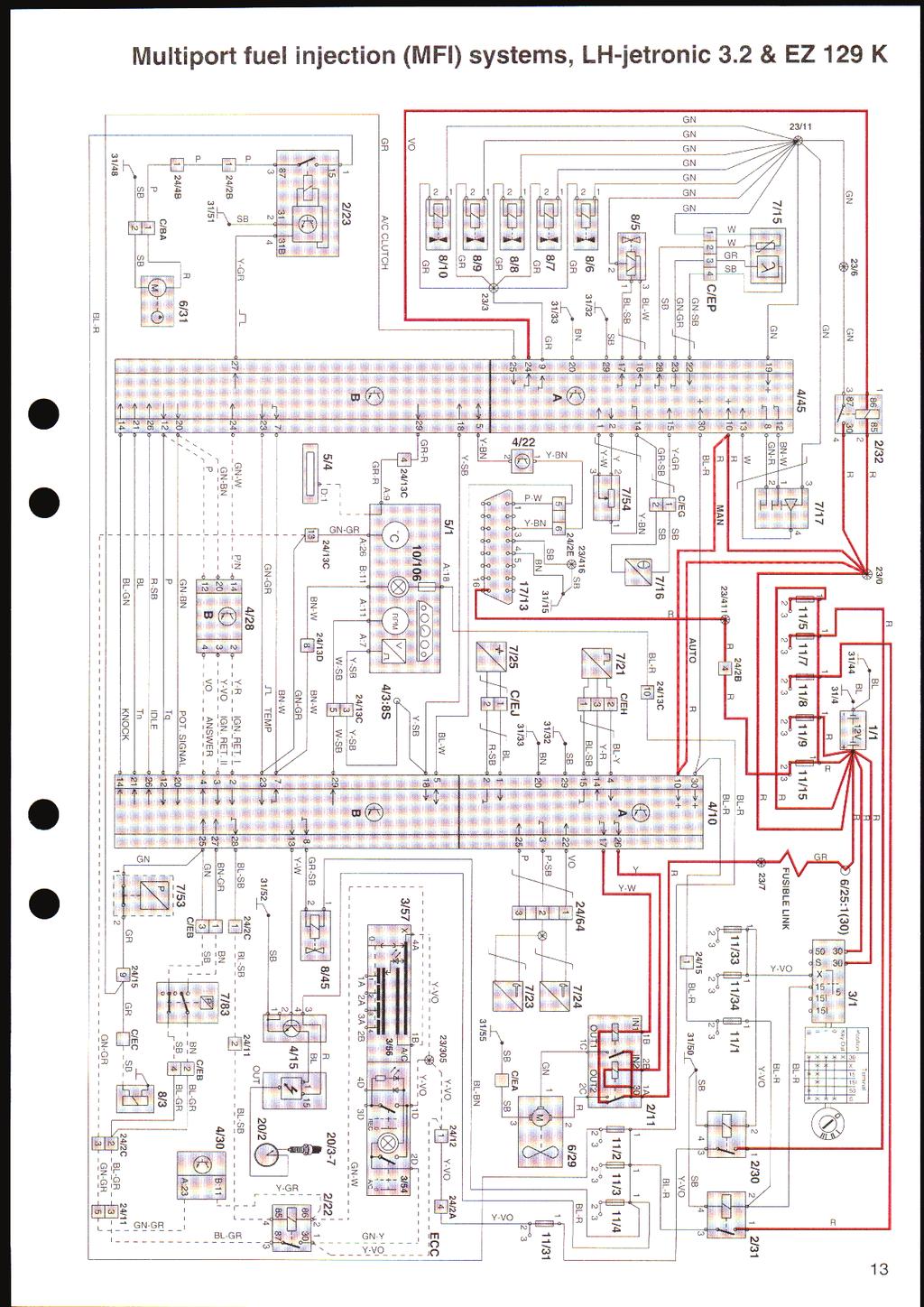
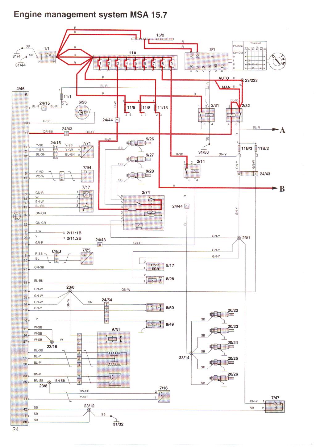
1 Cars with SRS Contents Fuses 1:2, 2:2 Fuses, Diesel 1:4, 2:4, 3:4, 4:4 Relays in positions Engine management system relays, Diesel Electrical distribution Electrical distribution, Diesel Ground point 31/71 Diesel ground point 31/32 Group 23/28 Frame contained PDF file, click here to view Multiport fuel injection (MFI) system, LH-jetronic 3.2 & EZ 129 K Multiport fuel injection (MFI) system, Fenix 5.2 Multiport fuel injection (MFI) system, Fenix 5.2 2:2 Sequential fuel injection (SFI) system, Motronic 4.3 (B 5204 T, B 5234 T) Sequential fuel injection (SFI) system Motronic 4.3 (B 5204 T, B 5234 T) 2:2 Sequential fuel injection (SFI) system, Motronic 4.3 (B 5254 S) Sequential fuel injection (SFI) system, Motronic 4.3 (B 5254 S) 2:2 Sequential fuel injection (SFI) system, Motronic 4.4 (B 5254 S) Sequential fuel injection (SFI) system, Motronic 4.4 (B 5254 S) 2:2 Sequential fuel injection (SFI) system, Motronic 4.4 (B 5254 T) Sequential fuel injection (SFI) system, Motronic 4.4 (B 5254 T) 2:2 Engine management system MSA 15.7 Engine management system MSA :2 Group 26 Engine coolant fan (FC), Diesel Group 27 Cruise control, Diesel Group 32/33
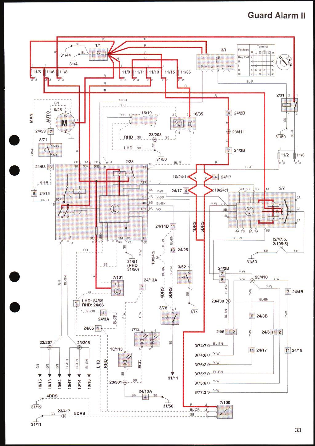
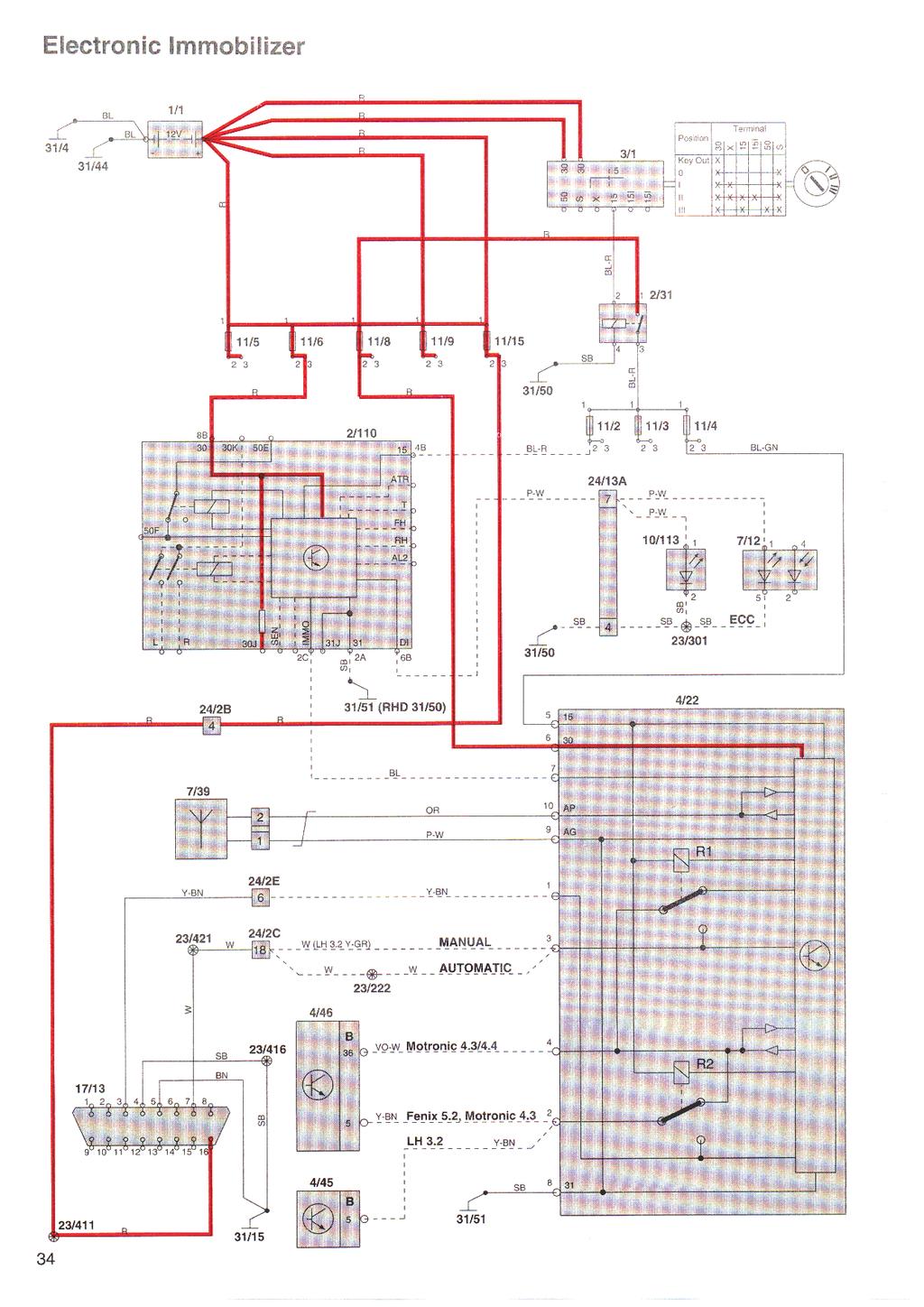
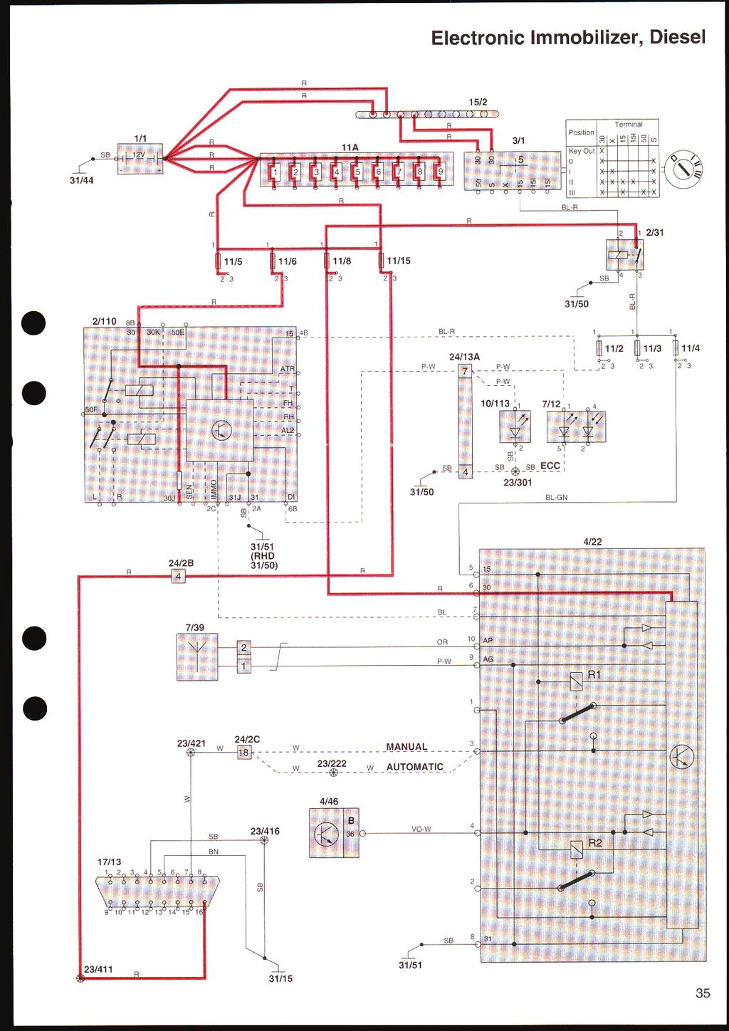
2 Power supply and starting system, Diesel Group 35 High and low beams High and low beam, Diesel Courtesy light, (4-door) Courtesy light, (5-door) Group 36 Guard Alarm II Electronic Immobilizer Electronic Immobilizer, Diesel Group 37 On-board diagnostic system (OBD system) On-board diagnostic system (OBD system), Diesel Group 38 Seat belt reminder Seat belt and key warning, USA, Canada, Korea Seat belt and key warning, Australia Combined instrument panel VDO Combined instrument panel VDO, Diesel Group 39 Radio with 4x50 W extra amplifier, 4-door Radio with 4x50 W extra amplifier, 5-door Group 43 AW electronically controlled automatic transmission (Fenix 5.2, Motronic 4.3/4.4) AW electronically controlled automatic transmission (MSA 15.7) Group 59 ABS Brake system and TRACS ABS Brake system and TRACS, Diesel Group 83 Central locking, 4-door Central locking, 5-door 2-stage central locking, 4-door 2-stage central locking, 5-door Central locking with deadlock, 4-door Central locking with deadlock, 5-door Remote control central locking
3 List of components (foldout) Feedback
4
5
6 This book deals with the electronic systems and their functions which are specific for 1997 cars or which differ from the corresponding electrical functions in the 1996 model year cars. Service Manual Section. 3 (39) Wiring diagrams can be referred to when Contents Fuses... 2 Fuses, Diesel... 4 Relays in positions Engine management system relays, Diesel... 9 Electrical distribution Electrical distribution, Diesel Ground point 31/ Diesel ground point 31/ Group 23/28 Multiport fuel injection (MFI) system, LH-jetronic 3.2 & EZ 129 K Multiport fuel injection (MFI) system, Fenix Sequential fuel injection (SFI) system, Motronic 4.3 (B 5204 T, B 5234 T) Sequential fuel injection (SFI) system, Motronic 4.3 (B 5254 S) Sequential fuel injection (SFI) system, Motronic 4.4 (B 5254 S) Sequential fuel injection (SFI) system, Motronic 4.4 (B 5254 T) Engine management system MSA Group 26 Engine coolant fan (FC), Diesel Group 27 Cruise control, Diesel Group 32/33 Power supply and starting system, Diesel Group 35 High and low beams High and low beam, Diesel Courtesy light, (4-door) Courtesy light, (5-door) Group 37 On-board diagnostic system (OBD system) On-board diagnostic system (OBD system), Diesel Group 38 Seat belt reminder Seat belt and key warning, USA, Canada, Korea Seat belt and key warning, Australia Combined instrument panel VDO Combined instrument panel VDO, Diesel Group 39 Radio with 4x50 W extra amplifier, 4-door Radio with 4x50 W extra amplifier, 5-door Group 43 AW electronically controlled automatic transmission (Fenix 5.2, Motronic 4.3/4.4) AW electronically controlled automatic transmission (MSA 15.7) Group 59 ABS Brake system and TRACS ABS Brake system and TRACS, Diesel Group 83 Central locking, 4-door Central locking, 5-door stage central locking, 4-door stage central locking, 5-door Central locking with deadlock, 4-door Central locking with deadlock, 5-door Remote control central locking List of components (foldout)... at end of manual Feedback... on last page of this manual Group 36 Guard Alarm II Electronic Immobilizer Electronic Immobilizer, Diesel Order no. TP (UK) Order no. TP (USA/CDN) We reserve the right to make alterations without prior notification 1
7
8
9
10
11
12
13
14
15
16
17
18
19
20
21
22
23
24
25
26
27
28
29
30
31
3/25 Switch, power sunroof 3/26 Control module, driver's seat 3/27 Control module, passenger's seat 3/28 Switch for heated driver's seat 3/29 Switch
 List of Components 1/1 Battery 2/1 Headlight relay with bulb failure sensor 2/2 Foglight relay 2/3 Regulator DIM-DIP 2/4 Intermittent wiper relay, windshield wipers 2/5 Relay, seat belt reminder/ignition
3/22 Switch for rear power window lifts 3/23 Switch for power door mirror, driver's side 3/24 Switch for power door mirror, passenger's side 3/25
 List of Components 1/1 Battery 2/2 Relay, front foglights USA/CDN 2/3 Regulator DIM-DIP 2/4 Intermittent relay, windshield wipers 2/5 Relay, seat belt reminder/ignition key warning 2/6 Bypass relay 151
Powertrain Management: Electrical Diagrams Fuel Injection System
 1995 Volvo 940 L4-2.3L SOHC VIN 88 B230F Copyright 2009, ALLDATA 9.70 Page 1 Powertrain Management: Electrical Diagrams Fuel Injection System Wiring Diagram 1995 Volvo 940 L4-2.3L SOHC VIN 88 B230F Copyright
Part 8 Dimensions and weight Engine SPECIFICATIONS
 Part 8 Dimensions and weight Engine SPECIFICATIONS Dimensions and weight Engine Fuel Service specifications Tires Fuses Overall length mm (in.) 4515 (177.7) Overall width mm (in.) 1810 ( 71.3) Overall
2000 Volkswagen Jetta GL
 Fig. 8: Locating Battery Fuse Panel Fuses Courtesy of VOLKSWAGEN UNITED STATES, INC. FUSE IDENTIFICATION (BATTERY FUSE PANEL) Fuse No. Amp Circuits Protected Rating 162 Engine Codes 50 Secondary Air Injector
Motronic September 1998
 The Motronic 1.8 engine management system was introduced with the 1992 Volvo 960. The primary difference between this Motronic system and the previous generation of Volvo LH-Jetronic engine management
Toledo 2005 Current Flow Diagram No. 651 / 1 Edition
 Page 1 of 6 Toledo 2005 Current Flow Diagram No. 651 / 1 Edition 12.2005 CAN bus network, drive train and diagnosis, LIN bus network from May 2005 Notes: For information concerning Position of relays and
Passat Fitting Locations No. 208 / 1 Edition
 Sivu 1/11 Passat Fitting Locations No. 208 / 1 Edition 02.2007 Relay and fuse assignment From May 2002 Relay locations on 13 position additional relay carrier above relay plate 1 - Radiator fan relay -
Part 8 SPECIFICATIONS
 Part 8 SPECIFICATIONS Dimensions and weight Engine Fuel Service specifications Tires Fuses Dimensions and weight P195/70R 14 tire Overall length 4783 (188.3) Overall width 1780 (70.1) Overall height 1416
POWER SOURCE (Current Flow Chart)
") POWER SOURCE (Current Flow Chart) The chart below shows the route by which current flows from the battery to each electrical source (Fusible Link, Circuit Breaker, Fuse, etc.) and other parts. The next
POWER SOURCE (Current Flow Chart) The chart below shows the route by which current flows from the battery to each electrical source (Fusible Link, Circuit Breaker, Fuse, etc.) and other parts. The next
FILE / FOR KEFICO ECU SERVICE MANUAL
 08 November, 2017 FILE / FOR KEFICO ECU SERVICE MANUAL Document Filetype: PDF 141.67 KB 0 FILE / FOR KEFICO ECU SERVICE MANUAL We aim for a 24-hour turnaround service. For more information please call
2011 AUDI A3 EXHAUST SYSTEM MANUAL WIRING DIAGRAM
 26 December, 2017 2011 AUDI A3 EXHAUST SYSTEM MANUAL WIRING DIAGRAM Document Filetype: PDF 158.39 KB 0 2011 AUDI A3 EXHAUST SYSTEM MANUAL WIRING DIAGRAM Audi A6 C6 2004 2011 Repair Manual. 1995 nissan
CIRCUIT DIAGRAMS GROUP CONTENTS HOW TO READ CIRCUIT DIAGRAMS VANITY MIRROR LIGHT JUNCTION BLOCK...
 90-1 GROUP 90 CONTENTS HOW TO READ................................. 90-4 JUNCTION BLOCK.............. 90-10 JOINT CONNECTOR............. 90-12 CENTRALIZED JUNCTION........ 90-13 POWER DISTRIBUTION SYSTEM..
SECTION 8 SPECIFICATIONS. Dimensions Service specifications
 SPECIFICATIONS SECTION 8 Dimensions... 342 Engine... 342 Fuel... 342 Service specifications... 343 Tires... 346 Fuses... 347 341 Dimensions Engine Fuel Overall length mm (in.) 4825 (190.0) Overall width
Position of Parts in Engine Compartment
 ELECTRICAL WIRING ROUTING [3S GTE] Position of Parts in Engine Compartment A 1 A/C Ambient Temp. Sensor D 1 Date Link Connector 1 (Check Connector) A 2 A/C Condenser Fan Motor D 2 Distributor A 4 A/C Magnetic
SECTION 6 4 SERVICE PROCEDURES AND SPECIFICATIONS. Electrical components
 SERVICE PROCEDURES AND SPECIFICATIONS Electrical components SECTION 6 4 Specifications........................................... 214 Checking battery condition and fluid level................... 218 Battery
ISUZU NPR LABOR TIME PDF
 23 November, 2018 ISUZU NPR LABOR TIME PDF Document Filetype: PDF 176.31 KB 0 ISUZU NPR LABOR TIME PDF Labor costs are estimated between $484 and $888 while. Isuzu Reach Van Warranty Limitations (time
Function description of crankcase ventilation. Engine CFI-Jetronic P
 01-0400 Function description of crankcase ventilation Engine 104.98 CFI-Jetronic 2 Air admission opening in crankcase 11 Cylinder head cover 2a Opening for oil outlet 12 Air cleaner 3 Gasket 13 Oil separator
G ELECTRICAL WIRING ROUTING
 G ELECTRICAL WIRING ROUTING Position of Parts in Engine Compartment A 1 A/C Condenser Fan Motor A 2 A/C Magnetic Clutch and Lock Sensor A 3 A/C Triple Pressure SW (A/C Dual and Single Pressure SW) A 4
G ELECTRICAL WIRING ROUTING
 G ELECTRICAL WIRING ROUTING Position of Parts in Engine Compartment A 1 A/C Condenser Fan Motor A 2 A/C Magnetic Clutch and Lock Sensor A 3 A/C Triple Pressure SW (A/C Dual and Signal Pressure SW) A 4
SECTION 6 4 SERVICE PROCEDURES AND SPECIFICATIONS. Electrical components
 SERVICE PROCEDURES AND SPECIFICATIONS Electrical components SECTION 6 4 Specifications........................................... 206 Checking battery condition................................ 210 Battery
MR2 U SECTION 8 SPECIFICATIONS. Dimensions and weight Service specifications MR2 (OM17475U)
") SPECIFICATIONS SECTION 8 Dimensions and weight...................................... 192 Engine.................................................... 192 Fuel.......................................................
SPECIFICATIONS SECTION 8 Dimensions and weight...................................... 192 Engine.................................................... 192 Fuel.......................................................
1.2 HFM Sequential Multiport Fuel injection/ignition System (HFM-SFI) Engine 111
 Engine 111") Preliminary work: Diagnosis - Malfunction Memory...................................... 11 Preparation for Test 1. Ignition: OFF 2. Connect test cable with socket box to engine control module (N3/4) according
Preliminary work: Diagnosis - Malfunction Memory...................................... 11 Preparation for Test 1. Ignition: OFF 2. Connect test cable with socket box to engine control module (N3/4) according
SECTION 8 SPECIFICATIONS. 06Camry_U (L/O 0507) Specifications. Dimensions and weights Service specifications
 Specifications. Dimensions and weights Service specifications") SPECIFICATIONS SECTION 8 Specifications Dimensions and weights.................................... 336 Engine.................................................... 336 Fuel.......................................................
SPECIFICATIONS SECTION 8 Specifications Dimensions and weights.................................... 336 Engine.................................................... 336 Fuel.......................................................
CONFIGURATION DIAGRAMS
 80-1 GROUP 80 CONFIGURATION DIAGRAMS CONTENTS CONFIGURATION DIAGRAMS......................... 80A SPLICE LOCATIONS................................. 80B 80A-2 GROUP 80A CONFIGURATION DIAGRAMS CONTENTS OVERALL
POWER SOURCE (Current Flow Chart)
") The chart below shows the route by which current flows from the battery to each electrical source (Fusible Link, Circuit Breaker, Fuse, etc.) and other parts. The next page and following pages show the
The chart below shows the route by which current flows from the battery to each electrical source (Fusible Link, Circuit Breaker, Fuse, etc.) and other parts. The next page and following pages show the
D D
 GF00.19-D-3100-24B Arrangement and assignment of terminal MODEL 901.6, 902.6, 903.6, 904.6, blocks of instrument cluster 905.6 with CODE (J58) Seat belt warning device with CODE (J59) Vehicle speed limit
BATTERY - HEADLIGHTS Special notes 80
 BATTERY - HEADLIGHTS Special notes 80 BATTERY - HEADLIGHTS Special notes 80 BATTERY - HEADLIGHTS Lens units 80 BATTERY - HEADLIGHTS Lens units 80 BATTERY - HEADLIGHTS Lens units 80 BATTERY - HEADLIGHTS
SECTION 8 SPECIFICATIONS 05 HIGHLANDER_U (L/O 0409) Specifications. Dimensions and weights Service specifications
 Specifications. Dimensions and weights Service specifications") SPECIFICATIONS SECTION 8 Specifications Dimensions and weights.................................... 406 Engine.................................................... 406 Fuel.......................................................
SPECIFICATIONS SECTION 8 Specifications Dimensions and weights.................................... 406 Engine.................................................... 406 Fuel.......................................................
SECTION 6 4 SERVICE PROCEDURES AND SPECIFICATIONS. Electrical components
 SERVICE PROCEDURES AND SPECIFICATIONS Electrical components SECTION 6 4 Specifications........................................... 220 Checking battery condition................................ 224 Battery
CONFIGURATION DIAGRAMS
 80A-1 GROUP 80A CONFIGURATION DIAGRAMS CONTENTS OVERALL CONFIGURATION DIAGRAM...................... 80A-2 HOW TO READ CONFIGURATION DIAGRAMS.................... 80A-3 ENGINE COMPARTMENT......... 80A-4
5/16/2017 ALLDATA Repair - Vehicle Information Volvo V L5-2.4L VIN 61 B5244S
 1/1 Battery 2/16 Relay, Intermittent Rear Window Wiping On/Off 2/17 Horn Relay 2/22 AC Relay 2/23 Fuel Pump Relay 2/29 Relay, Extended D1 Feed 2/30 X Feed Overload Relay 2/31 15-Feed Overload Relay 2/32
MAINTENANCE INFORMATION
 MAINTENANCE INFORMATION 1994 Volvo 960 1992-96 MAINTENANCE Volvo Maintenance Information 960 Sedan 960 Wagon * PLEASE READ THIS FIRST * NOTE: For scheduled maintenance intervals and the related fluid capacities,
2UZ-FE ENGINE. Engine Control System TOYOTA TUNDRA - NEW FEATURES
 2UZ-FE ENGINE Engine Control System General The engine control system of the 2UZ-FE engine on the 06 has following systems. System SFI Sequential Multiport Fuel Injection ESA Electronic Spark Advance ETCS-i
Fuses. Fuses FUSE BOX LOCATIONS
 FUSE BOX LOCATIONS 206 When a fuse box lid is removed, take care to protect the box from moisture, and refit the lid at the earliest opportunity. Engine compartment - fuse box access: 1. Remove the two
1996 Mustang. 1. Remove air cleaner outlet tube (9B659). Refer to Section Disconnect battery ground cable (14301). Refer to Section
. Refer to Section Disconnect battery ground cable (14301). Refer to Section") REMOVAL AND INSTALLATION Fuel Charging Wiring Removal and Installation 1. Remove air cleaner outlet tube (9B659). Refer to Section 03-12. 2. Disconnect battery ground cable (14301). Refer to Section 14-01.
REMOVAL AND INSTALLATION Fuel Charging Wiring Removal and Installation 1. Remove air cleaner outlet tube (9B659). Refer to Section 03-12. 2. Disconnect battery ground cable (14301). Refer to Section 14-01.
Instrument cluster. Стр. 1 из 9. The following components are integrated in the instrument cluster: Instrument Cluster Control Module J285
 Volkswagen Passat B6 2005 - Instrument cluster Стр. 1 из 9 90-1 Instrument cluster General information The following components are integrated in the instrument cluster: Instrument Cluster Control Module
L PART NUMBER OF CONNECTORS
 L PART NUMBER OF CONNECTORS Code Part Name Part Number Code Part Name Part Number A 1 A/C Ambient Temp. Sensor 90980-11070 B15 Blower Motor Controller (Rear) 90980-11136 A 2 A/C Magnetic Clutch 90980-11271
FILE - WIRING DIAGRAM FOR VOLVO 850 FUEL PUMP RELAY ARCHIVE
 15 February, 2019 FILE - WIRING DIAGRAM FOR VOLVO 850 FUEL PUMP RELAY ARCHIVE Document Filetype: PDF 226.81 KB 0 FILE - WIRING DIAGRAM FOR VOLVO 850 FUEL PUMP RELAY ARCHIVE Volvo 240 fuel relay location
G ELECTRICAL WIRING ROUTING
 2 6 G ELECTRICAL WIRING ROUTING [2JZ-GTE] Position of Parts in Engine Compartment A 1 A/C Ambient Temp Sensor A 2 A/C Condensor Fan Motor A 3 A/C Triple Pressure SW (A/C Dual and Single Pressure SW) A
SC300/400 NEW FEATURES. 1UZ FE Engine Item No. of Cyls. & Arrangement 8 Cylinder, V Type
 51 1UZ FE ENGINE 1. Description Various improvement have been made to the 1UZ FE engine in order to realize weight reduction and low friction performance. As a result, the engine provides both high power
J POWER SOURCE (Current Flow Chart)
") J POWER SOURCE (Current Flow Chart) 374 J 375 J POWER SOURCE (Current Flow Chart) Driver Side J/B (See Page 26) 7.5A ECU ACC Automatic Air Conditioning (Front) Automatic Light Control Back Door Opener
J POWER SOURCE (Current Flow Chart) 374 J 375 J POWER SOURCE (Current Flow Chart) Driver Side J/B (See Page 26) 7.5A ECU ACC Automatic Air Conditioning (Front) Automatic Light Control Back Door Opener
G ELECTRICAL WIRING ROUTING
 2 6 G ELECTRICAL WIRING ROUTING Position of Parts in Engine Compartment A1 A/C Front Magnetic Valve A3 A/C Magnetic Clutch A6 A/T Flud Temp. Sensor A7 ABS Actuator A8 ABS Actuator A10 ABS Speed Sensor
Lotus Service Notes Section MVc
 Lotus Service Notes MVc - CIRCUIT DIAGRAMS Exige Sport 350 models from '16my start of production For '12my - '16my exige s models refer to separate section mva for manual or mvb for automatic transmission
GROUP CONTENTS FUSIBLE LINK, FUSE AND IOD OR STORAGE CONNECTOR RELAY SENSOR INSPECTION TERMINAL...
 70-1 GROUP 70 CONTENTS FUSIBLE LINK, FUSE AN IO OR STORAGE......... 70-2 INSPECTION TERMINAL......... 70-3 GROUNING................... 70-4 GROUNING CABLE............ 70-8 RELAY........................
Passenger Car Drive Authorization Systems. Service Technology Guide
 Passenger Car Drive Authorization Systems Service Technology Guide Mercedes-Benz Service Passenger Car Drive Authorization Systems Service Technology Guide Daimler AG Technical Information and Workshop
Symptom Suspected Area See page Ignition switch is not set to each position. 11.Ignition switch BE 14
 BE2 BODY ELECTRICAL PROBLEM SYMPTOMS TABLE IGNITION SWITCH AND KEY UNLOCK WARNING SWITCH BE0ON18 Ignition switch is not set to each position. 11.Ignition switch BE14 Key unlock warning system does not
Lotus Service Notes Section MVd
 Lotus Service Notes MVd - CIRCUIT DIAGRAMS EXIGE SPORT 380 MODELS FROM '17MY START OF PRODUCTION FOR '12MY - '16MY EXIGE S MODELS REFER TO SEPARATE SECTION MVa FOR MANUAL OR MVb FOR AUTOMATIC TRANSMISSION
Position of Parts in Engine Compartment
 [1UZ FE] Position of Parts in Engine Compartment A 1 A/C Ambient Temp. Sensor E 4 Engine Coolant Temp. Sensor (Water Temp. Sensor A 2 A/C Dual Pressure SW and A/C High Pressure SW (for Cooling Fan)) A
Fuse/Relay Information
 BD 10/24/91 kd 11/12 smk 11/14/91 MC 4/8/92 bd 4/14/92 92 PRELUDE /Relay Information Under-hood /Relay Box 47 46 45 44 43 42 41 40 39 31 49 48 51 50 37 36 35 34 33 32 C941 (To ABS motor relay) 38 C942
CONFIGURATION DIAGRAMS
 80A-1 GROUP 80A CONFIGURATION DIAGRAMS CONTENTS OVERALL CONFIGURATION DIAGRAM...................... 80A-2 HOW TO READ CONFIGURATION DIAGRAMS.................... 80A-3 ENGINE COMPARTMENT......... 80A-4
List of components 1:9
 List of components 1:9 1/1 Battery 1/1 Battery 2/22 Relay, climate control system 2/32 Main relay, engine management system 2/35 Relay, starter motor 2/64 Auxiliary light relay 2/64 Auxiliary light relay
SECTION 6 4 SERVICE PROCEDURES AND SPECIFICATIONS. Electrical components
 SERVICE PROCEDURES AND SPECIFICATIONS Electrical components SECTION 6 4 Specifications........................................... 214 Checking battery condition................................ 218 Battery
Transporter Current Flow Diagram No. 80 / 1 Edition
 Side 1 av 13 Transporter Current Flow Diagram No. 80 / 1 Edition 05.2003 2.5 l/65 kw direct injection turbo diesel, engine code AJT From May 1999 2.5 l/75 kw direct injection turbo diesel, engine codes
Caddy Current Flow Diagram No. 86 / 1 Edition
 Page 1 of 9 Caddy Current Flow Diagram No. 86 / 1 Edition 09.2003 1.9 l/47 kw Naturally aspirated diesel engine with direct injection, engine code AYQ From May 2000 Relay locations 3 - Terminal 30 voltage
CIRCUIT DIAGRAMS GROUP CONTENTS HOW TO READ CIRCUIT DIAGRAMS BACKUP LIGHT TURN SIGNAL LIGHT AND HAZARD WARNING LIGHT...
 90-1 GROUP 90 CIRCUIT DIAGRAMS CONTENTS HOW TO READ CIRCUIT DIAGRAMS................................. 90-4 JUNCTION BLOCK.............. 90-10............. 90-12 CENTRALIZED JUNCTION........ 90-18 POWER
TECHNICAL DEVELOPMENT OF VEHICLE JE0X LAUNCH DATE OF VEHICLE EQUIPPED WITH THE PASSENGER COMPARTMENT CONNECTION UNIT (BII)
") TECHNICAL NOTE Edition Anglaise 77 11 201 886 SEPTEMBER 1998 Type 3100A Service 0422 Sub-section JE0 X 87 87 Engine: Gearbox: XXX XXX Basic manual: M.R. 315 N.T. 3028A TECHNICAL DEVELOPMENT OF VEHICLE
TECHNICAL NOTE Edition Anglaise 77 11 201 886 SEPTEMBER 1998 Type 3100A Service 0422 Sub-section JE0 X 87 87 Engine: Gearbox: XXX XXX Basic manual: M.R. 315 N.T. 3028A TECHNICAL DEVELOPMENT OF VEHICLE
List of components 1:6
 List of components 1:6 1/1 Battery 1/1 Battery 2/14 Relay, glow plug unit 2/22 Relay, climate control system 2/32 Main relay, engine management system 2/33 Relay, fuel system 2/35 Starter motor relay 2/64
ENGINE 1UZ FE ENGINE DESCRIPTION 35 ENGINE 1UZ FE ENGINE
 35 ENGINE 1UZ FE ENGINE ENGINE 1UZ FE ENGINE DESCRIPTION The 1UZ FE engine in the 95 LS400 is a V8, 4.0 liter, 32 valve DOHC engine. Its construction and operation are basically the same as those of the
Section 3 Electrical system
 S40(04-) Section 3 Electrical system Section 3 Electrical system Group 31 Battery System voltage, with ignition off: A newly charged battery may have a higher voltage. 12.5-12.7 V Battery capacity Cold
Index. Abbreviation list Alphabetical index What to do if
 Index Abbreviation list... 470 Alphabetical index... 471 What to do if...... 481 469 Abbreviation list Abbreviation/Acronym list ABBREVIATIONS ABS ACC ALR CRS DISP ECU EDR ELR GAWR GVWR I/M LATCH LED LSD
Fuse/Relay Information
 /Relay Information Under-dash /Relay Box C901 (To turn signal/hazard relay) C902 (To blower motor relay) C903 (To rear window defogger relay) C405 C404 C904 (To integrated control unit) C602 (To dashboard
Index. Abbreviation list Alphabetical index What to do if
 Index Abbreviation list... 478 Alphabetical index... 479 What to do if...... 489 477 Abbreviation list Abbreviation/Acronym list ABBREVIATIONS ABS ACC ALR CRS DISP ECU EDR ELR GAWR GVWR I/M LATCH LED LSD
1993 ENGINE PERFORMANCE Volkswagen Basic Diagnostic Procedures. Cabriolet, Corrado SLC, EuroVan, Fox, Golf, GTI, Jetta, Passat GL, Passat GLX
 Article Text ARTICLE BEGINNING 1993 ENGINE PERFORMANCE Volkswagen Basic Diagnostic Procedures Cabriolet, Corrado SLC, EuroVan, Fox, Golf, GTI, Jetta, Passat GL, Passat GLX INTRODUCTION The following diagnostic
1993 FD3S Touring Trim Electrical FSM Index/Supplement
 1993 FD3S Touring Trim Electrical FSM Index/Supplement Purpose: This is simply a searchable index of connectors that are found in the various 1993 FD3S wiring harnesses. Each entry shows the purpose of
EPUB - VW GOLF TDI MANUAL GEARBOX DIAGRAM
 19 February, 2018 EPUB - VW GOLF TDI MANUAL GEARBOX DIAGRAM Document Filetype: PDF 522.88 KB 0 EPUB - VW GOLF TDI MANUAL GEARBOX DIAGRAM The way is by getting vw golf tdi manual gearbox diagram as one
Fast Fuel Injection Parts Manual READ ONLINE
 Fast Fuel Injection Parts Manual READ ONLINE Diesel Injection Pump, Diesel Injector Pump - Buy Auto Parts - Browse our parts catalog to find any other auto parts or Diesel Injector Pump - Manual The Diesel
FUSES & CIRCUIT BREAKERS Ford Taurus LX
 Page 1 of 7 ARTICLE BEGINNING FUSES & CIRCUIT BREAKERS Interior Fuse Panel Identification Fuse panel is located to left of steering column under instrument panel. To expose fuse panel, pull release bar
BMW 850 IS PRODUCTS MANUAL
 16 February, 2018 BMW 850 IS PRODUCTS MANUAL Document Filetype: PDF 378.32 KB 0 BMW 850 IS PRODUCTS MANUAL The best air cleaner that captures and cleans mist and smoke. BMW F 750 GS and F 850 GS India
1993 WIRING DIAGRAMS Volkswagen Wiring Diagrams. Volkswagen; Corrado
 Article Text Tuesday, December 07, 1999 11:21PM ARTICLE BEGINNING 1993 WIRING DIAGRAMS Volkswagen Wiring Diagrams Volkswagen; Corrado COMPONENT LOCATION MENU COMPONENT LOCATIONS TABLE ÄÄÄÄÄÄÄÄÄÄÄÄÄÄÄÄÄÄÄÄÄÄÄÄÄÄÄÄÄÄÄÄÄÄÄÄÄÄÄÄÄÄÄÄÄÄÄÄÄÄÄÄÄÄÄÄÄÄÄÄÄÄÄÄÄ
Bars Professional. CODE WORK SUPPORT ENGINE Petrol Engine. + Nissan Anti-Theft System
 Bars Professional INFINITI / NISSAN 1990-2011 VERSION: 2V09 DATE: NOV, 2012 MODELS EQUIPPED WITH 14-PIN CONNECTOR AND OBD-II CONNECTOR ( NON-CAN VEHICLES) (NOTE 1) SYSTEM YEAR CAN COMMUNICTION CLEAR ACTIVATION
Volvo Fuel Injection Fault Tracing Volvo 1800 Picture
 We have made it easy for you to find a PDF Ebooks without any digging. And by having access to our ebooks online or by storing it on your computer, you have convenient answers with volvo fuel injection
Diagnostic Trouble Code (DTC) memory, checking and erasing
 memory, checking and erasing") Page 1 of 49 01-12 Diagnostic Trouble Code (DTC) memory, checking and erasing Check DTC Memory (function 02) - Connect VAS5051 tester Page 01-7 and select vehicle system "01 - Engine electronics". Engine
Page 1 of 49 01-12 Diagnostic Trouble Code (DTC) memory, checking and erasing Check DTC Memory (function 02) - Connect VAS5051 tester Page 01-7 and select vehicle system "01 - Engine electronics". Engine
file://f:\alfa\elearn\web\tempschprint.html AUTOMATIC TRANSMISSION
 Strona 1 z 8 AUTOMATIC TRANSMISSION 166 Strona 2 z 8 AUTOMATIC TRANSMISSION - Description An electronic management system supervises and governs the operation of the AISIN automatic transmission. An electronic
3.2 LH Sequential Multiport Fuel Injection System (LH-SFI) Engine 120
 Engine 120") Preliminary work: Diagnosis - Diagnostic Trouble Code (DTC) Memory.......................... 11 Preparation for Test 1. Ignition: OFF 2. Remove LH-SFI control module (N3/2 or N3/3). 3. After determining
Preliminary work: Diagnosis - Diagnostic Trouble Code (DTC) Memory.......................... 11 Preparation for Test 1. Ignition: OFF 2. Remove LH-SFI control module (N3/2 or N3/3). 3. After determining
FUSES & CIRCUIT BREAKERS
 FUSES & CIRCUIT BREAKERS FUSES & CIRCUIT BREAKERS 1989-95 FUSES & CIRCUIT BREAKERS Ford Motor Co. INTERIOR FUSE PANEL IDENTIFICATION (1983-88 MODELS) On all models, the fuse panel is located under the
VALEO HEVAC (P38 NRR) - System Overview
 - System Overview") VALEO HEVAC (P38 NRR) - System Overview Custom Manufactured by Valeo for the P38 Range Rover as an Air condition control module option on everything except the very base model, which has only 3 rotary
VALEO HEVAC (P38 NRR) - System Overview Custom Manufactured by Valeo for the P38 Range Rover as an Air condition control module option on everything except the very base model, which has only 3 rotary
FUSES & CIRCUIT BREAKERS
 FUSES & CIRCUIT BREAKERS FUSES & CIRCUIT BREAKERS 1995 General Motors Corp. FUSES & CIRCUIT BREAKERS FUSE PANEL IDENTIFICATION (INSTRUMENT PANEL) Friday, November 27, 2009 5:05:35 5:05:39 PM Page 1 2005
Position of Parts in Engine Compartment
 ELECTRICAL WIRING ROUTING [5S FE] Position of Parts in Engine Compartment A 1 A/C Condenser Fan Motor E 4 Engine Coolant Temp. Sensor (EFI Water Temp. A 2 A/C Magnetic Clutch and Lock Sensor Sensor) A
Audi A3 Current Flow Diagram No. 75 / 1 Edition Audi A3 (1,8 l litre fuel injection engine, 110 kw, Motronic, 4-cylinder) engine codes AQA
 engine codes AQA") Strona 1 z 10 Audi A3 Current Flow Diagram No. 75 / 1 Edition 09.1999 Audi A3 (1,8 l litre fuel injection engine, 110 kw, Motronic, 4-cylinder) engine codes AQA From model year 1999 Audi A3 (1,8 l litre
Strona 1 z 10 Audi A3 Current Flow Diagram No. 75 / 1 Edition 09.1999 Audi A3 (1,8 l litre fuel injection engine, 110 kw, Motronic, 4-cylinder) engine codes AQA From model year 1999 Audi A3 (1,8 l litre
G ELECTRICAL WIRING ROUTING [2ZZ GE] Position of Parts in Engine Compartment
![G ELECTRICAL WIRING ROUTING [2ZZ GE] Position of Parts in Engine Compartment](/thumbs/82/84806793.jpg "G ELECTRICAL WIRING ROUTING [2ZZ GE] Position of Parts in Engine Compartment") G ELECTRICAL WIRING ROUTING [2ZZ GE] Position of Parts in Engine Compartment A 1 A/C Magnetic Clutch A 2 ABS Speed Sensor Front LH A 3 ABS Speed Sensor Front RH A 4 Airbag Sensor Front LH A 5 Airbag Sensor
G ELECTRICAL WIRING ROUTING [2ZZ GE] Position of Parts in Engine Compartment A 1 A/C Magnetic Clutch A 2 ABS Speed Sensor Front LH A 3 ABS Speed Sensor Front RH A 4 Airbag Sensor Front LH A 5 Airbag Sensor
Position of Parts in Engine Compartment
 ELECTRICAL WIRING ROUTING [5S FE] Position of Parts in Engine Compartment A 1 A/C Ambient Temp. Sensor D 1 Distributor A 2 A/C Condenser Fan Motor A 3 A/C Idle Up VSV E 1 ECT Solenoid A 4 A/C Magnet Clutch
Lotus Service Notes - Exige - all Models from '18 MY VIN KH_ CCT Diagrams Section MVg
 Lotus Service Notes - Exige - all Models from '18 MY VIN KH_10083 - CCT Diagrams Section MVg MVg - CIRCUIT DIAGRAMS EXIGE - ALL MODELS FITTED WITH A138M0195F AIR BAG CONTROL UNIT - FROM '19MY VIN KH_10083
ABS DIAGRAM 97 RAV USER GUIDE E-BOOK
 29 December, 2018 ABS DIAGRAM 97 RAV USER GUIDE E-BOOK Document Filetype: PDF 420.2 KB 0 ABS DIAGRAM 97 RAV USER GUIDE E-BOOK Details of all Service Brakes/Brake Light On problems of Toyota RAV4. - the
Driver information module (DIM), installation/removal, component replacement
, installation/removal, component replacement") 1(4) Driver information module (DIM), installation/removal, component replacement Note! As the illustrations in this service information are used for different model years and / or models, some variation
1(4) Driver information module (DIM), installation/removal, component replacement Note! As the illustrations in this service information are used for different model years and / or models, some variation
1 of :51
 1 of 5 13.05.2012 19:51 Μεταχειρισμένα Αυτοκίνητα Βρες τις πληροφορίες που ψάχνεις στην οθόνη του υπολογιστή σου! www.xo.gr 4x4 Αυτοκίνητο Αναζήτησε Ανάμεσα σε 76 Μοντέλα, Aυτό που Σου Ταιριάζει από 12.690
Audi A6. Automatic gearbox multitronic 01J from model year 2005 Notes: Current Flow Diagram No. 22 / 1. Edition For information concerning
 Current Flow Diagram No. 22 / 1 Edition 08.2007 Automatic gearbox multitronic 01J from model year 2005 Notes: For information concerning Position of relays and fuses Multi-pin connections Control units
AUTOMOTIVE TECHNOLOGY Service and Maintenance
 AUTOMOTIVE TECHNOLOGY Service and Maintenance Don Knowles Knowles Automotive Training Moose Jaw, Saskatchewan CANADA Jack Erjavec, Series Editor Professor Emeritus Columbus State Community College Columbus,
Vehicle health check ABS - ANTI LOCK BRAKE MODULE. Fault Codes. Parameters Snapshot ACM - AUDIO CONTROL MODULE. Fault Codes. Parameters Snapshot
 Vehicle health check Health check done on: 11/06/2015 08:17:25 VIN: xxxxxxxxxxxxxx Plate Number: Not Registered ABS - ANTI LOCK BRAKE MODULE Brake / Configuration and programming version --------- DTC
C915 - A147 Powertrain control module (PCM) C916 - A7 ABS control module
 C916 - A7 ABS control module") C915 - A147 Powertrain control module (PCM) C916 - A7 ABS control module C1152 - K11 Intermittent wiper relay, front C1153 - K1 Rear window heater relay C1154 - K18 ABS main relay C1155 - K25 ABS Pump
C915 - A147 Powertrain control module (PCM) C916 - A7 ABS control module C1152 - K11 Intermittent wiper relay, front C1153 - K1 Rear window heater relay C1154 - K18 ABS main relay C1155 - K25 ABS Pump
COOLING FAN DEFOGGERS HORN POWER ANTENNA POWER DOOR LOCKS POWER MIRRORS POWER SEATS POWER WINDOWS RADIO 2.3L. Fig. 1: 2.3L Turbo, Cooling Fan Circuit
 COOLING FAN 2.3L Fig. 1: 2.3L Turbo, Cooling Fan Circuit DEFOGGERS Fig. 2: Defogger Circuit, W/ Electronic ATC Fig. 3: Defogger Circuit, W/O Electronic ATC HORN Fig. 4: Horn Circuit POWER ANTENNA Fig.
ENGINE 1UZ-FE ENGINE 45. System Outline GS LS400 SFI
 ENGINE 1UZ-FE ENGINE 45 ENGINE CONTROL SYSTEM 1. General The engine control system of the new 1UZ-FE engine is basically same in construction and operation as that of the 1UZ-FE engine for the 98 LS400.
Fuses and Relays CONTENTS FUSE AND RELAY BOARDS ( ) K4M690-K4M694 ENGINES 13
 K4M690-K4M694 ENGINES 13") CONTENTS PASSENGER COMPARTMENT FUSE UNIT (1016) 2 CHILD SAFETY RELAY (750) 8 PASSENGER COMPARTMENT CENTRAL UNIT (645) 9 FUSE AND RELAY BOARDS (233-299-336-597-784-1047-1639) K4M690-K4M694 ENGINES 13 FUSE
CONTENTS PASSENGER COMPARTMENT FUSE UNIT (1016) 2 CHILD SAFETY RELAY (750) 8 PASSENGER COMPARTMENT CENTRAL UNIT (645) 9 FUSE AND RELAY BOARDS (233-299-336-597-784-1047-1639) K4M690-K4M694 ENGINES 13 FUSE
ENGINE AND EMISSION CONTROL
 17-1 GROUP 17 ENGINE AND EMISSION CONTROL CONTENTS ENGINE CONTROL 17-2 GENERAL INFORMATION 17-2 AUTO-CRUISE CONTROL SYSTEM 17-3 GENERAL INFORMATION 17-3 CONSTRUCTION AND OPERATION 17-5 17-7 GENERAL INFORMATION
LIST OF COMPONENTS (SECTION 1) B001: mixed bridge block 1 B002: mixed bridge block 2 B003: mixed bridge block 3 BB00: battery BB01: battery assembly
 B001: mixed bridge block 1 B002: mixed bridge block 2 B003: mixed bridge block 3 BB00: battery BB01: battery assembly") LIST OF COMPONENTS (SECTION 1) B001: mixed bridge block 1 B002: mixed bridge block 2 B003: mixed bridge block 3 BB00: battery BB01: battery assembly (rear) BB02: battery assembly (lower front) ВВ0З: battery
LIST OF COMPONENTS (SECTION 1) B001: mixed bridge block 1 B002: mixed bridge block 2 B003: mixed bridge block 3 BB00: battery BB01: battery assembly (rear) BB02: battery assembly (lower front) ВВ0З: battery
Bosch Motronic Engine Management Manual File Type
 BOSCH MOTRONIC ENGINE MANAGEMENT MANUAL FILE TYPE PDF - Are you looking for bosch motronic engine management manual file type Books? Now, you will be happy that at this time bosch motronic engine management
GM HUMMER H2 SERVICE MANUAL (230 MB) - DOWNLOAD! DIY Factory Service_Repair_Maintenance Manual ! - PDF Service Manual
 - DOWNLOAD! DIY Factory Service_Repair_Maintenance Manual ! - PDF Service Manual") 2003-2007 GM HUMMER H2 SERVICE MANUAL (230 MB) - DOWNLOAD! DIY Factory Service_Repair_Maintenance Manual 2004 2005 2006! - PDF Service Manual DOWNLOAD HERE "2003-2007 GM HUMMER H2 SERVICE MANUAL (230 MB)
2003-2007 GM HUMMER H2 SERVICE MANUAL (230 MB) - DOWNLOAD! DIY Factory Service_Repair_Maintenance Manual 2004 2005 2006! - PDF Service Manual DOWNLOAD HERE "2003-2007 GM HUMMER H2 SERVICE MANUAL (230 MB)
Symptom Suspect Area See page. 11.Ignition Switch 12.Power Source Circuit. Symptom Suspect Area See page
 BE2 PROBLEM SYMPTOMS TABLE IGNITION SWITCH: BE18204 Ignition switch is not set to each position. KEY UNLOCK WARNING SWITCH: 11.Ignition Switch 12.Power Source Circuit BE15 Key unlock warning system does
SAAB ACC DIAGRAM EPUB
 07 December, 2017 SAAB ACC DIAGRAM EPUB Document Filetype: PDF 365.55 KB 0 SAAB ACC DIAGRAM EPUB LH Fuel Injection System Overview. The cabin temperature sensor is positioned in the dashboard under the
Function description
 30-0006 Function description Electronic accelerator (EA) Block diagram Overvoltage protection EA control relay, Models 124, 202 (power supply) Idle speed control Base, Models (ISC) 129,140, 124.034/036