1628 State Road 114 Rensselaer, IN Phone Facsimile
|
|
|
- Cecil Bond
- 5 years ago
- Views:
Transcription

1 1628 State Road 114 Rensselaer, IN Phone Facsimile 1
2 1. Introduction And Warranty Introduction Warranty Safety Safety Alert Symbol and Signal Words Towing Hazards Driving Too Fast Trailer Not Properly Coupled to Truck Overloading Improper Load Distribution Inappropriate Cargo Brakes and Lights Clearance Hydraulics Maintenance Loading and Unloading Hazards from Modifying Equipment Safety Warning Labels Reporting Safety Defects Detachable Gooseneck Trailers Coupling Truck to Trailer Providing an Adequate Truck Trailer Information Before Attempting to Couple Truck to Trailer Couple Truck to Trailer Pre-trip Inspection Loading and Unloading Detach Gooseneck from Trailer Deck Connect Gooseneck to Trailer Deck Uncouple Truck Uncouple Truck from Trailer Fold Tail Trailers Coupling Truck to Trailer Providing an Adequate Truck Trailer Information Before Attempting to Couple Truck to Trailer Couple Truck to Trailer Pre-trip Inspection Loading and Unloading Fold Tail Operation Position Folding Tail For Loading/Unloading Position Fold Tail For Transport Deck Ramp Operation Winch Operation Extend Winch Cable Using Remote Extend Winch Cable Manually Extend Winch Cable Using Hydraulic Control Lever Retract Winch Cable with Remote Retract Winch Cable with Hydraulic Control Lever Uncouple Truck Uncouple Truck from Trailer Traveling Axle Trailers Coupling Truck to Trailer Providing an Adequate Truck Trailer Information Before Attempting to Couple Truck to Trailer Couple Truck to Trailer Pre-trip Inspection Loading and Unloading Hydraulic Controls Position Trailer for Loading/Unloading
3 Position Trailer for Transport Winch Operation Extend Winch Cable Using Remote Extend Winch Cable Manually Extend Winch Cable Using Hydraulic Control Lever Retract Winch Cable with Remote Retract Winch Cable with Hydraulic Control Lever Uncouple Truck Uncouple Truck from Trailer Towing Trailer Wheels and Tires Alignment Inspections And Maintenance Every Day Pre-Trip Inspections Inspect Trailer Every Week Drain Trailer Air Tanks Lubrication Detachable Gooseneck Trailers Fold Tail and Traveling Axle Trailers Traveling Axle Trailers As Necessary Hydraulic System Tires Wheels Wheel Ends
4 1. INTRODUCTION AND WARRANTY 1.1 INTRODUCTION Read and understand this manual before using your trailer and follow all of the safety instructions. Keep all manuals provided with your trailer in a safe place inside your truck at all times. Some components may have separate instruction manuals. Where this manual indicates that you should read another manual, and you do not have that manual, contact your dealer or Talbert Mfg for assistance. Information provided in this manual was current as of the issue date. Talbert Mfg reserves the right to make design changes without further notice or liability. 1.2 WARRANTY TALBERT MANUFACTURING One Year Limited Structural Warranty Effective Limited Structural Warranty: Talbert Manufacturing, Inc. warrants each new trailer structure manufactured by us to be free from defects in material and workmanship under normal usage and service for a period of one (1) year after THE DATE OF MANUFACTURE of the trailer. Trailer structure shall be considered the framework of the trailer (gooseneck, main frame and/or rear frame) which is fabricated by Talbert Manufacturing, Inc. This warranty is not transferable. Structural Warranty Coverage Schedule: Talbert Manufacturing, Inc. shall bear that portion of the cost of repairing or replacing any trailer structure found to be defective within the one year warranty period based on the following schedule: Up to One year: 100% Beyond One year 0% Talbert Manufacturing, Inc. warrants other manufactured components of its trailers (other than the trailer structure), for a period of one (1) year after THE DATE OF MANUFACTURE of the trailer. Talbert Manufacturing, Inc. makes no warranty of loading ramps, or of components supplied by other manufacturers and suppliers of components or accessories. Talbert Manufacturing, Inc. will assign to the customer any warranty rights it receives from the component manufacturer or supplier. Please contact your dealer in the event of a problem with the trailer or its components. In general, components will be subject to the manufacturers warranties: Wear parts, including light bulbs, brake lining and flooring: Are not warranty items. Regulatory Warranty: Our trailers are manufactured to conform to all applicable Federal Motor Vehicle Safety Standards in effect on the date of manufacture. We do not warrant trailers to be in compliance with any other federal, state or local laws, rules, regulations, or orders. Specific Exclusions: Our limited warranty is subject to specific exclusions, and does not apply to any trailer which has been: 1) subjected to or operated with loads which, at any time, have exceeded the trailer s rated capacity or design limits; 2) repaired or altered outside of Talbert s factory in any way so as, in our judgment, to affect its stability or reliability; and 3) subject to misuse, negligence, accident, or has been operated in a manner expressly prohibited in the instructions; or not operated in accordance with practices approved by Talbert Manufacturing, Inc. Please contact the factory prior to undertaking any repair or alteration including welding, burning, or drilling holes on or in the frame of your Talbert Trailer. Our Obligation: Under the specific warranties set forth above, our obligation is limited to making good at our factory any trailer structure or Talbert Manufacturing, Inc. manufactured component which shall be returned to us, transportation charges prepaid, up to one year after THE DATE OF MANUFACTURE of the trailer (one (1) year in the case of Talbert Manufacturing, Inc. manufactured components) and which our examination discloses to have been defective. Coverage of the trailer structure shall be in accordance with the schedule set forth above. Any warranty claim must be made immediately to the dealer who, in turn, notifies our Warranty Department. Talbert will not be obligated to pay for any repairs, alterations or parts which are made prior to authorization from our warranty department. Exclusive Warranty: This warranty is the exclusive warranty given for trailers sold by Talbert Manufacturing, Inc. It is expressly in lieu of all other warranties, whether oral, written or implied, including the implied warranties of merchantability or fitness for a particular purpose, and of all other obligations or liabilities on the part of Talbert Manufacturing, Inc. We neither assume nor authorize any dealers or other persons to assume for us, any other liability in connection with the sale of our trailers. Limitation of Liability: In no case will we be liable for any consequential or incidental damages incurred by you, including, but limited to, loss of sales, profit or goodwill; loss of use of the trailer or any associated equipment; cost of rentals, substitute equipment, facilities or services; downtime costs; attorneys fees; or losses or claims of your customers or other third parties. This warranty card, within, must be executed and returned to Talbert Manufacturing, Inc. accompanied by a copy of the original sales invoice/bill of sales within ten (10) days of first retail sale. Failure to return and execute warranty card within this proposed time frame will void all warranty obligations expressed or implied. 4
5 Introduction And Warranty This contract shall be governed by and continued in accordance with the laws of the state of Indiana, and actions or lawsuits shall be tried exclusively in the state court located in Jasper County, Indiana or the federal court located in Lafayette Indiana Talbert Warranty Card Dealer Name Date of manufacture Customer Name Customer Address State Zip Serial Number Model Date of Sale Customer Signature Date This card must be returned signed by the customer within 10 working days from date of sale to activate warranty. Lack of either signature will void the warranty. 5
6 2. SAFETY 2.1 SAFETY ALERT SYMBOL AND SIGNAL WORDS This Owner s Manual covers trailers produced by Talbert Mfg. Before towing, operating or servicing a Talbert trailer, you must read, understand and follow the instructions and safety warnings in this manual. Your trailer may not be equipped with some of the optional equipment shown in the illustrations in this manual. The safety information in this manual is denoted by the safety alert symbol: ^ The level of risk is indicated by the following signal words. ^ DANGER DANGER Indicates a hazardous situation, which, if not avoided, will result in death or serious injury. WARNING Indicates a hazardous situation, which, if not avoided, could result in death or serious injury. ^ CAUTION CAUTION Indicates a hazardous situation, which, if not avoided, could result in minor or moderate injury. NOTICE NOTICE Indicates a situation that could result in damage to the equipment or other property. The following are general safety issues pertaining to the use of the trailer, please read prior to use. 2.2 TOWING HAZARDS Loss of control of the truck/trailer combination can result in death or serious injury. The most common causes for loss of control are: Driving too fast. Incorrect coupling. Overloading. Improper load distribution. Shifting cargo DRIVING TOO FAST If you drive too fast, the trailer is more likely to sway, thus increasing the possibility for loss of control. Collision hazard. Driving too fast for conditions can result in loss of control and may result death or serious injury. Adjust speed down when towing trailer. 6
7 Safety TRAILER NOT PROPERLY COUPLED TO TRUCK A secure coupling is vital. Uncoupling can result in death or serious injury. Collision hazard. An improperly coupled trailer can result in death or serious injury. Before towing trailer, verify that: The coupler is properly secured and locked. Trailer landing gear is fully retracted. Lights and air hoses connected. Perform pre-trip inspection OVERLOADING An overloaded trailer can result in loss of control, which may result in death or serious injury. Overloading may also result in tire, wheel, axle or structural failure, and also increased stopping distances. Loss of control hazard. Overloading can result in death or serious injury. Do not load a trailer so that the Gross Vehicle Weight Rating (GVWR) or Gross Axle Weight Rating (GAWR) is exceeded IMPROPER LOAD DISTRIBUTION Improper load distribution can result in poor stability and handling. Refer to Loading and Unloading for more information. Uneven load distribution can cause tire, wheel, axle or structural failure. Be sure your load is evenly distributed frontto-rear and side-to-side. OPERATOR is responsible for determining proper load distribution. Collision hazard. An improperly loaded trailer can result in failure or loss of control, leading to death or serious injury. Evenly distribute the load throughout the trailer. 7
8 Safety INAPPROPRIATE CARGO Carry only the cargo that your trailer was designed for. A trailer must not be used to carry certain items, such as people, hazardous and/or flammable substances. Never transport people on a trailer. Do not transport flammable, explosive, poisonous or other dangerous materials on your trailer unless the trailer is specifically designed to do so. 2.3 BRAKES AND LIGHTS Be sure that the trailer brakes and all of the trailer lights are functioning properly, prior to each tow. Collision hazard. 2.4 CLEARANCE Failure to connect the electrical connector and air hoses will result in inoperable trailer lights and brakes, and can lead to collision. Before each tow, verify that all lights and brakes work properly. Collision hazard. Know the height, width and length of the trailer and the load on the trailer. Always be aware of clearances. 2.5 HYDRAULICS Pressurized fluids can penetrate the skin. Hydraulic hoses can fail from age, damage and exposure. Do not search for hydraulic leaks without body and face protection. A tiny, almost invisible leak can penetrate the skin, thereby requiring immediate medical attention. Use wood or cardboard to detect hydraulic leaks, never use your hands. 8
9 Safety 2.6 MAINTENANCE Crushing hazard. Before performing inspections, service or maintenance: Park trailer on firm level ground. Set brakes and turn truck engine off and remove ignition key. Chock tires. Support trailer with properly rated and placed stands. 2.7 LOADING AND UNLOADING ^ DANGER Electrocution hazard. Contact with overhead electrical lines will cause serious injury or death. Electrocution can occur without contact. Be sure the load on your trailer does not contact an electrical line. Falling hazard. The trailer deck may be slippery if wet or ice and snow covered. Use caution while on the trailer to avoid falling. Crushing and severing hazard. The moving fold tail and deck ramp can crush and sever hands and limbs. Keep away from moving parts. 2.8 HAZARDS FROM MODIFYING EQUIPMENT Altering the trailer may cause an unsafe condition and may void the manufacturers warranty. Before making any alteration to your Talbert Trailer, contact your dealer or Talbert Mfg and describe the alteration you are contemplating. 9


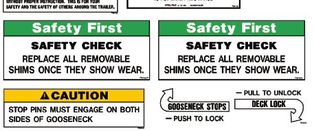
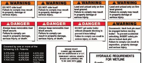
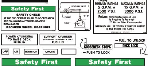
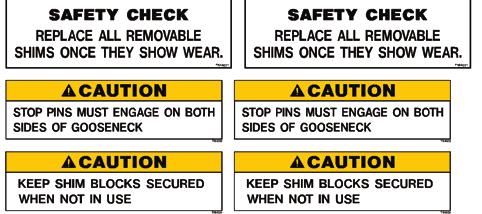
10 Safety 2.9 SAFETY WARNING LABELS 10
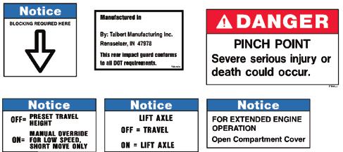
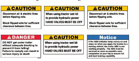
11 Safety 11
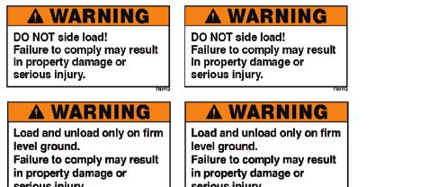

12 Safety 12
13 Safety 13

 in addition to notifying Talbert Mfg.")
14 Safety To protect against death or serious injury, labels must be on the trailer and must be legible. If any of these labels are missing or cannot be read, call Talbert Manufacturing Inc. at for replacement labels REPORTING SAFETY DEFECTS If you believe that your vehicle has a defect that could cause a crash or could cause injury or death, you should immediately inform the National Highway Traffic Safety Administration (NHTSA) in addition to notifying Talbert Mfg. If NHTSA receives similar complaints, it may open an investigation, and if it finds that a safety defect exists in a group of vehicles, it may order a recall and remedy campaign. However, NHTSA cannot become involved in individual problems between you, your dealer, or Talbert Mfg. To contact NHTSA, you may either call the Vehicle Safety Hotline toll-free at (TTY: ), go to or write to: Administrator, NHTSA, 1200 New Jersey Avenue S.E. Washington, DC You can also obtain other information about motor vehicle safety from 14
15 3. DETACHABLE GOOSENECK TRAILERS 3.1 COUPLING TRUCK TO TRAILER PROVIDING AN ADEQUATE TRUCK The truck must be matched to the Gross Vehicle Weight Rating (GVWR) of your trailer. If you already have a truck, know your truck s tow rating and make certain the trailer s rated capacity is less than or equal to the truck s rated towing capacity. ^ DANGER Loss of control hazard. Use of an under-rated truck could result in loss of control, and can lead to death or serious injury. Be sure your truck is rated for the Gross Vehicle Weight Rating (GVWR) of your trailer TRAILER INFORMATION The Certification / VIN tag is located on the front of the gooseneck. See Figure 3-1. Figure 3-1: Certification / VIN Tag Location The trailer Certification / VIN tag contains the following information: MANUFACTURER: Talbert Mfg. See Figure 3-1. DATE: Month and year the trailer was manufactured. See Figure 3-1. GVWR: The Gross Vehicle Weight Rating is the maximum allowable gross weight of the trailer and its contents with the listed wheel rims. See Figure 3-1. GAWR ALL AXLES: The Gross Axle Weight Rating is the maximum gross weight that all axles can support. See Figure 3-1. TIRE: The tire size recommended for your trailer and load range. See Figure 3-1. RIMS: The rim size recommended for your trailer. See Figure
16 Detachable Gooseneck Trailers COLD INFLATION PRESSURE: The pounds per square inch is the tire pressure (Kilopascals / Pounds per Square Inch) measured when cold. See Figure 3-1. VIN: The Vehicle Identification Number. See Figure 3-1. TYPE: Type of trailer. See Figure 3-1. MODEL: The model number for your trailer. See Figure 3-1. CAPACITY: The trailer capacity in tons. See Figure BEFORE ATTEMPTING TO COUPLE TRUCK TO TRAILER 1. Check the condition of the kingpin and mounting plate. Wipe the kingpin clean and inspect it for flat spots, cracks and pits. Uncoupling hazard. A worn, bent or damaged kingpin can fail while towing, which can result in death or serious injury. Inspect the kingpin and kingpin plate for wear and damage. Replace a worn or damaged kingpin or kingpin plate before towing trailer. 2. Verify that the kingpin plate and fifth wheel fasteners are tight and welds are sound. Uncoupling hazard. A loose kingpin or fifth wheel can result in the trailer uncoupling, which can result in death or serious injury. Verify the kingpin and fifth wheel are tight. 3. Lubricate the fifth wheel lock mechanism and verify it will move freely. 4. Clear all hoses and electrical cables from the coupling area. 5. Verify the fifth wheel locks are open. Crushing hazard. Death or serious injury may occur if the trailer drops. Keep bystanders away from trailer while coupling COUPLE TRUCK TO TRAILER 1. Place wheel chocks behind the trailer tires. 2. Place the truck directly in front of the trailer in a straight line. See Figure 3-2. NEVER back under the trailer at an angle. 16
17 Detachable Gooseneck Trailers 3. Back the truck until close to the trailer. Figure 3-2: Align Truck with Trailer for Coupling 4. Apply the truck parking brakes and place transmission in neutral. 5. Release air from truck suspension (if equipped). 6. Inspect the height of the trailer vs the fifth wheel. The kingpin plate on the front of the trailer should first contact the fifth wheel 4-6 inches rearward of the fifth wheel centerline. The trailer should rise slightly when the truck is backed under it. If the trailer is too low, the truck may strike and damage the front of the trailer. If the trailer is too high, it will not couple correctly. Uncoupling hazard. Trailer must be at the correct height to couple to truck. Verify trailer is at the proper height before coupling. Failure to couple properly could cause an uncoupling of truck to trailer, and dropping of the trailer and load. 7. Verify that the kingpin and fifth wheel are aligned. 8. Slowly back the truck keeping the kingpin aligned with the fifth wheel. Continue backing until the fifth wheel locks firmly on the kingpin. Attempt to pull forward as a test to verify the fifth wheel is locked. Do not attempt to move the truck and trailer at this time. 9. Apply the truck parking brake, place transmission in neutral, stop truck engine and remove ignition key. 10. Inspect the coupling. See Figure 3-4. Verify there is no space between the kingpin plate and the fifth wheel. If there is space, the kingpin may be on top of the fifth wheel jaws. Raise the trailer with the landing gear, pull the fifth wheel release lever and pull the truck ahead. Repeat steps 6-10 again to couple the trailer correctly. Figure 3-4: Fifth Wheel Checks 11. Go under the trailer with a flashlight and look into the back of the fifth wheel. Verify the fifth wheel jaws (A) have closed around the shank of the kingpin and the fifth wheel lock lever is in the locked position. See Figure
, service hose to glad hand (2) and supply hose to glad hand (3). See Figure 3-6. 14.")
18 Detachable Gooseneck Trailers 12. Inflate the truck suspension (if equipped). Figure 3-5: Fifth Wheel Jaws Closed Around Kingpin Shank 13. Connect the 7-pin harness to electrical connector (1), service hose to glad hand (2) and supply hose to glad hand (3). See Figure Connect the pressure and return hydraulic hoses to hydraulic connectors (4). See Figure 3-6. Figure 3-6: Connect Hoses and Electrical Connector Pressurized fluids can penetrate the skin. Hydraulic hoses can fail from age, damage and exposure. Do not search for hydraulic leaks without body and face protection. A tiny, almost invisible leak can penetrate the skin, thereby requiring immediate medical attention. Use wood or cardboard to detect hydraulic leaks, never your hands. 15. Start the hydraulic system. 16. Push power cylinders lever (1) in to raise the trailer deck. See Figure 3-7. Raise the trailer deck until the stop pins (2) are above the adjustment shim blocks (3) on each side of the gooseneck. See Figure
19 Detachable Gooseneck Trailers Figure 3-7: Power Cylinders Lever Figure 3-8: Pin and Adjustment Shim Block 17. Push the stop pin control (4) to extend the stop pins. Verify stop pins are extended on both sides of gooseneck. See Figure 3-9. Figure 3-9: Stop Pin Control 18. Pull power cylinders lever out to lower the deck and transfer the load onto the shim blocks. Release the power cylinders lever. 19. Press the trailer air supply valve in the truck to fill the trailer air tanks. Do not release parking brakes. 20. Disengage the hydraulic system. 21. Perform pre-trip inspection PRE-TRIP INSPECTION Perform the inspections and checks before towing trailer: 19
20 Detachable Gooseneck Trailers Check all lights for proper operation. Check that ABS light on street side rear corner of the trailer is not illuminated. If lamp is illuminated, see the axle and brake manufacturers manual. Check that all safety decals are in place and in good, readable condition. Check that all reflectors are in place and in good condition. Check air pressure on all tires. Air pressure is listed on the Certification/VIN tag. Check and inspect all tires. If a tire has a bald spot, bulge, cut or cords showing, replace the tire(s) before towing trailer. Check wheel lug torque. Check the wheel hub fluid level and also for signs of lubricant leakage. Verify that air suspension springs are inflated. Check all electrical harness and air hoses from for damage. Listen for air leaks in hoses and air suspension. Check brakes for wear and verify the brakes function properly. Ensure all ramps are folded and secured in storage position. Repair or replace any worn, damaged, leaking, broken or non-functioning items before towing the trailer. Failure to perform a pre-trip inspection could cause damage to the trailer or serious injury or death. 20
21 3.2 LOADING AND UNLOADING Detachable Gooseneck Trailers Improper trailer loading causes many accidents and deaths. To safely load a trailer, you must consider the overall load weight and load distribution. The load distribution must be such that no component part of the trailer is loaded beyond its rating. You must be sure that the load distribution does not exceed the rating of the tires, wheels and axles. Collision hazard. An overloaded trailer may result in death or serious injury. Do not load a trailer so that the Gross Vehicle Weight Rating (GVWR) or Gross Axle Weight Rating (GAWR) is exceeded DETACH GOOSENECK FROM TRAILER DECK 1. Park the trailer on firm and level ground and engage the parking brakes on truck. 2. Connect hydraulic hoses to trailer if not already connected. 3. Start the hydraulic system. 4. Pull and rotate manual gooseneck/deck lock safety pin (1). See Figure Pull gooseneck /deck lock control (2) to unlock gooseneck from deck. See Figure Figure 3-10: Gooseneck/Deck Safety Pin Figure 3-11: Gooseneck/Deck Lock Control 5. Push power cylinders lever (3) in to raise the trailer deck. See Figure Raise the trailer deck until the gooseneck stops (4) are above the shim blocks (5) on each side of the gooseneck. See Figure
22 Detachable Gooseneck Trailers Figure 3-12: Power Cylinder Lever Figure 3-13: Pin and Adjustment Shim Block 6. Pull the stop pin control (6) to retract the stop pins. See Figure Verify stop pins are retracted on both sides of gooseneck. Crushing and severing hazard. Figure 3-14: Gooseneck Stop Pin Control The moving trailer deck can crush and sever feet. Keep away from trailer deck while in motion. 7. Pull the power cylinder lever out and lower deck to the ground. Ensure the deck pin (7) on each side of gooseneck does not bind against surrounding frame. See Figure
 and air hoses (9) between")
 at base of")


23 Detachable Gooseneck Trailers Figure 3-15: Deck Pin Clearance 8. Disconnect electrical connection (8) and air hoses (9) between gooseneck and deck. See Figure This will set trailer brakes. Store electrical and air lines in storage area (10) at base of gooseneck. See Figure Figure 3-16: Electrical and Air Hoses Figure 3-17: Storage Area 9. Push support control lever (11) in and engage truck frame with gooseneck support arm. See Figure Support cylinder must NOT be used to lift the deck. Figure 3-18: Support Cylinder Lever 23
24 Detachable Gooseneck Trailers Avoid sharp turns. Making sharp turns with gooseneck supported on truck may result in gooseneck falling from truck which could result in serious injury. Do not make sharp turns. 10. Pull truck forward with gooseneck, moving straight ahead if possible to simplify re-attaching later. After disconnecting from trailer deck, further adjustment of the gooseneck may be required to prevent gooseneck from contacting the ground. 11. Shut off the hydraulic system. 12. Load trailer. To prevent serious injury or death during equipment loading: 1. Load on level ground. 2. Do not attempt to side load equipment. 3. Keep the equipment straight with the ramps and trailer throughout the loading process. Use a spotter. 4. Chock the truck and trailer tires. 5. Equipment loading is dangerous. Proceed slowly and cautiously at all times. 6. Load only with sufficient light. 7. Secure the load with properly rated chains or straps. 8. DO NOT exceed the Gross Vehicle Weight Rating (GVWR) of the trailer. 9. Keep bystanders clear when vehicle is being loaded. 10. Review loading safety instructions with all operators. 13. Secure load to trailer with properly rated devices CONNECT GOOSENECK TO TRAILER DECK 1. Align truck with trailer, and slowly back truck with gooseneck until gooseneck guide engages deck ramp. Continue until guide seats. Set truck brakes. Pull support cylinder control arm (1) out and retract support arm fully. 24
. See Figure 3-21.")

25 Detachable Gooseneck Trailers Figure 3-19: Gooseneck Support Cylinder Control Lever 2. Push gooseneck/deck lock control (2) in. See Figure If pin locks, insert safety pin (3). See Figure If pin does not lock, bump truck slightly until pin locks, then insert safety pin. See Figure Figure 3-20: Gooseneck/Deck Lock Control Figure 3-21: Gooseneck/Deck Safety Pin 3. Connect the electrical connection (4) and air hoses (5) between gooseneck and deck. See Figure Activate the hydraulic power system. Figure 3-22: Electrical and Air Hoses 25
 in, see Figure 3-23 and raise deck until gooseneck stop pins (7) are free to engage both sides of the gooseneck. See Figure 3-24.")

. See Figure 3-25.")
26 Detachable Gooseneck Trailers 4. Push power cylinder lever (6) in, see Figure 3-23 and raise deck until gooseneck stop pins (7) are free to engage both sides of the gooseneck. See Figure Push the stop pin control (8) to extend the stop pins. See figure Ensure both stop pins are fully extended and are not obstructed. Figure 3-23: Power Cylinder Lever Figure 3-24: Stop Pin and Stop Pin Control 5. Pull power cylinder lever out, and lower deck until gooseneck stop pins hold the weight of the deck. Shut off the hydraulic system. 6. Fold ramps onto deck and fasten to deck with chains (9). See Figure Figure 3-25: Ramp Chains Note: Metal shim blocks (10) of equal thickness may be provided to regulate deck height and/or fifth wheel height. To gain deck height (or decrease fifth wheel height) adjustment blocks may be located between stop pins and diagonal gooseneck section. Both sides of gooseneck MUST be the same. See Figure Failure to properly install shim blocks could cause serious injury or death. 26


27 Detachable Gooseneck Trailers Figure 3-26: Shim Block 7. Perform pre-trip inspection. See Section UNCOUPLE TRUCK UNCOUPLE TRUCK FROM TRAILER 1. Park the trailer on firm and level ground. 2. Connect hydraulic hoses to trailer if not already connected. 3. Start the hydraulic system. 4. Push power cylinders lever (1) in to raise the trailer deck. See Figure Raise the trailer deck until the gooseneck stop pins (2) are above the shim blocks (3) on each side of the gooseneck. See Figure Figure 3-27: Power Cylinders Lever Figure 3-28: Pin and Adjustment Block Crushing and severing hazard. The moving trailer deck can crush and sever feet. Keep away from trailer deck while in motion. 5. Pull the stop pin control (4) to retract the stop pins. See Figure Verify both stop pins are fully retracted. 27

28 Detachable Gooseneck Trailers Figure 3-29: Stop Pin Control 6. Pull power cylinder lever out, and lower deck to the ground. Shut off the hydraulic system. 7. Disconnect the hydraulic hoses, air hoses and electrical connector from the couplers on the front of the trailer. Install dust covers on hydraulic fittings. See figure Pull the truck fifth wheel release lever. Figure 3-30: Disconnect Hoses and Electrical Connector 9. Release air in truck suspension (if equipped) and pull truck forward until fifth wheel comes out from under the trailer. 10. Stop with truck frame under trailer. 11. Apply parking brake and place transmission in neutral. 12. If necessary, adjust the gooseneck height so the gooseneck is not resting on the truck frame. 13. Check the area and drive truck forward until clear of trailer. 28

29 4. FOLD TAIL TRAILERS 4.1 COUPLING TRUCK TO TRAILER PROVIDING AN ADEQUATE TRUCK The truck must be matched to the Gross Vehicle Weight Rating (GVWR) of your trailer. If you already have a truck, know your truck s tow rating and make certain the trailer s rated capacity is less than or equal to the truck s rated towing capacity. ^ DANGER Loss of control hazard. Use of an under-rated truck could result in loss of control, and can lead to death or serious injury. Be sure your truck is rated for the Gross Vehicle Weight Rating (GVWR) of your trailer TRAILER INFORMATION The Certification / VIN tag is located on the street side of the trailer, near the front. Figure 4-1: Certification / VIN Tag Location The trailer Certification / VIN tag contains the following information: MANUFACTURER: Talbert Mfg. See Figure 4-1. DATE: Month and year the trailer was manufactured. See Figure 4-1. GVWR: The Gross Vehicle Weight Rating is the maximum allowable gross weight of the trailer and its contents with the listed wheel rims. See Figure 4-1. GAWR ALL AXLES: The Gross Axle Weight Rating is the maximum gross weight that all axles can support. See Figure 4-1. TIRE: The tire size recommended for your trailer and load range. See Figure 4-1. RIMS: The rim size recommended for your trailer. See Figure
30 Fold Tail Trailers COLD INFLATION PRESSURE: The pounds per square inch is the tire pressure (Kilopascals / Pounds per Square Inch) measured when cold. See Figure 4-1. VIN: The Vehicle Identification Number. See Figure 4-1. TYPE: Type of trailer. See Figure 4-1. MODEL: The model number for your trailer. See Figure 4-1. CAPACITY: The trailer capacity in tons. See Figure BEFORE ATTEMPTING TO COUPLE TRUCK TO TRAILER 1. Check the condition of the kingpin and mounting plate. Wipe the kingpin clean and inspect it for flat spots, cracks and pits. Uncoupling hazard. A worn, bent or damaged kingpin can fail while towing, which can result in death or serious injury. Inspect the kingpin and kingpin plate for wear and damage. Replace a worn or damaged kingpin or kingpin plate before towing trailer. 2. Verify that the kingpin plate and fifth wheel fasteners are tight and welds are sound. Uncoupling hazard. A loose kingpin or fifth wheel can result in the trailer uncoupling, which can result in death or serious injury. Verify the kingpin and fifth wheel are tight. 3. Lubricate the fifth wheel lock mechanism and verify it will move freely. 4. Clear all hoses and electrical cables from the coupling area. 5. Verify the fifth wheel locks are open. Crushing hazard. Death or serious injury may occur if the trailer drops. Keep bystanders away from trailer while coupling COUPLE TRUCK TO TRAILER 1. Place wheel chocks behind the trailer tires. 2. Place the truck directly in front of the trailer in a straight line. See figure 4-2. NEVER back under the trailer at an angle. 30
31 Fold Tail Trailers 3. Back the truck until close to the trailer. Figure 4-2: Align Truck with Trailer for Coupling 4. Apply the truck parking brakes and place transmission in neutral. 5. Release air from truck suspension (if equipped). 6. Inspect the height of the trailer vs the fifth wheel. The kingpin plate on the front of the trailer should first contact the fifth wheel 4-6 inches rearward of the fifth wheel centerline. See Figure 4-3. The trailer should rise slightly when the truck is backed under it. If the trailer is too low, the truck may strike and damage the front of the trailer. If the trailer is too high, it will not couple correctly. Adjust the landing gear as needed to achieve the correct trailer height. Uncoupling hazard. Trailer must be at the correct height to couple to truck. Verify trailer is at the proper height before coupling. 7. Verify that the kingpin and fifth wheel are aligned. Figure 4-3: Coupling Truck to Trailer 8. Slowly back the truck keeping the kingpin aligned with the fifth wheel. Continue backing until the fifth wheel locks firmly on the kingpin. Attempt to pull forward as a test to verify the fifth wheel is locked. Do not attempt to move the truck and trailer at this time. 9. Apply the truck parking brake, place transmission in neutral, stop truck engine and remove ignition key. 10. Inspect the coupling. See Figure 4-4. Verify there is no space between the kingpin plate and the fifth wheel. If there is space, the kingpin may be on top of the fifth wheel jaws. Raise the trailer with the landing gear, pull the fifth wheel release lever and pull the truck ahead. Repeat steps 6-10 again to couple the trailer correctly. 31
32 Fold Tail Trailers Figure 4-4: Fifth Wheel Checks 11. Go under the trailer with a flashlight and look into the back of the fifth wheel. Verify the fifth wheel jaws (A) have closed around the shank of the kingpin and the fifth wheel lock lever is in the locked position. See Figure Inflate the truck suspension (if equipped). Figure 4-5: Fifth Wheel Jaws Closed Around Kingpin Shank 13. Connect the 7-pin harness to electrical connector (1), service hose to glad hand (2) and supply hose to glad hand (3). See Figure Connect the pressure and return hydraulic hoses to hydraulic connectors (4). See Figure 4-6. Figure 4-6: Connect Hoses and Electrical Connector Pressurized fluids can penetrate the skin. Hydraulic hoses can fail from age, damage and exposure. Do not search for hydraulic leaks without body and face protection. A tiny, almost invisible leak can penetrate the skin, thereby requiring immediate medical attention. Use wood or cardboard to detect hydraulic leaks, never your hands. 32
33 Fold Tail Trailers 15. Move crank handle (1) from the storage position (left portion of Figure 4-7) to installed position (right portion of figure). Talbert Mfg uses a two speed landing gear from several different manufacturers. High speed may be in on some models and out on others. Engage the crank handle (1) to the shaft and turn to retract the landing gear. Return the landing gear crank handle to the storage position. Figure 4-7: Two Speed Landing Gear 16. Press the trailer air supply valve in the truck to fill the trailer air tanks. Do not release parking brakes. 17. Perform pre-trip inspection PRE-TRIP INSPECTION Perform the inspections and checks before towing trailer: Check all lights for proper operation. Check that ABS light on street side rear corner of the trailer is not illuminated. If lamp is illuminated, see the axle and brake manufacturers manual. Check that all safety decals are in place and in good, readable condition. Check that all reflectors are in place and in good condition. Check air pressure on all tires. Air pressure is listed on the Certification/VIN tag. Check and inspect all tires. If a tire has a bald spot, bulge, cut or cords showing, replace the tire(s) before towing trailer. Check wheel lug torque. Check the wheel hub fluid level and also for signs of lubricant leakage. Verify that air suspension springs are inflated. Check all electrical harness and air hoses from for damage. Listen for air leaks in hoses and air suspension. Check brakes for wear and verify the brakes function properly. Ensure all ramps are folded and secured in storage position. Repair or replace any worn, damaged, leaking, broken or non-functioning items before towing the trailer. Failure to perform a pre-trip inspection could cause damage to the trailer or serious injury or death. 33

34 4.2 LOADING AND UNLOADING Fold Tail Trailers Improper trailer loading causes many accidents and deaths. To safely load a trailer, you must consider the overall load weight and load distribution. The load distribution must be such that no component part of the trailer is loaded beyond its rating. You must be sure that the load distribution does not exceed the rating of the tires, wheels and axles. Collision hazard. An overloaded trailer may result in death or serious injury. Do not load a trailer so that the Gross Vehicle Weight Rating (GVWR) or Gross Axle Weight Rating (GAWR) is exceeded FOLD TAIL OPERATION Figure 4-8: Fold Tail Controls 1 Front Deck Ramp Control 2 Rear Ramp Control 3 Rear Flip Tail Control POSITION FOLDING TAIL FOR LOADING/UNLOADING Crushing and severing hazard. The moving fold tail can crush and sever hands and limbs. Keep away from moving parts and pinch points. 1. Park the trailer on firm and level ground. 2. Connect hydraulic hoses to trailer if not already connected. 3. Start the hydraulic system. 4. Lower the trailer suspension by moving the valve to the ON position. This will stabilize the trailer for loading and unloading. 34
 to extend tail to the load position. See figure 4-11. Figure 4-11: Rotate Flip Ramp to Load Position 7.")
35 Fold Tail Trailers Figure 4-9: Lower Trailer Suspension 5. Pull rear ramp control (2) to raise tail ramp to the highest position. See figure Figure 4-10: Raise Tail Ramp to Highest Position 6. Pull rear flip tail control (3) to extend tail to the load position. See figure Figure 4-11: Rotate Flip Ramp to Load Position 7. Push rear ramp control (2) to lower the rear ramp to the load/unload position. Support brackets (5) on each side of the tail ramp must be resting on the ground or surface. See figure

 of the trailer. 9. Keep bystanders clear when vehicle is being loaded. 10. Review loading safety instructions with all operators. 9. Secure load to trailer with properly rated devices.")
36 Fold Tail Trailers 8. Safely load equipment onto trailer. Figure 4-12: Lower Tail Ramp to Load/Unload Position To prevent serious injury or death during equipment loading: 1. Load on level ground. 2. Do not attempt to side load equipment. 3. Keep the equipment straight with the ramps and trailer throughout the loading process. Use a spotter. 4. Chock the truck and trailer tires. 5. Equipment loading is dangerous. Proceed slowly and cautiously at all times. 6. Load only with sufficient light. 7. Secure the load with properly rated chains or straps. 8. DO NOT exceed the Gross Vehicle Weight Rating (GVWR) of the trailer. 9. Keep bystanders clear when vehicle is being loaded. 10. Review loading safety instructions with all operators. 9. Secure load to trailer with properly rated devices POSITION FOLD TAIL FOR TRANSPORT Crushing and severing hazard. The moving fold tail can crush and sever hands and limbs. Keep away from moving parts and pinch points. 1. Pull rear ramp control (2) to raise tail ramp to the highest position. See Figure
 to rotate flip ramp to the transport position. See Figure 4-14.")

37 Fold Tail Trailers Figure 4-13: Raise Tail Ramp to Highest Position 2. Push rear flip tail control (3) to rotate flip ramp to the transport position. See Figure Figure 4-14: Rotate Flip Ramp to Transport Position 3. Push rear ramp control to lower rear ramp to the transport position. See Figure Figure 4-15: Lower Tail Ramp to Transport Position 4. Raise the trailer suspension by moving the valve to the OFF position. See Figure
 to raise deck ramp.")
38 Fold Tail Trailers Figure 4-16: Raise Trailer Suspension DECK RAMP OPERATION Crushing and severing hazard. The moving deck ramp can crush and sever hands and limbs. Keep away from moving parts and pinch points. 1. Connect hydraulic hoses to trailer if not already connected. 2. Start the hydraulic system. 3. Pull front deck ramp control (1) to raise deck ramp. See Figure Ensure the deck ramp is fully raised before placing a load on the deck ramp. Do not place a load on a partially raised deck ramp. NOTICE Risk of damage to deck ramp cylinders. Placing a load on a partially raised deck ramp may cause damage to the deck ramp hydraulic cylinders. Deck ramp must be fully lowered or fully raised before placing a load on the deck ramp. 38

39 Fold Tail Trailers Figure 4-17: Deck Ramp in Raised Position 4. Push front deck ramp control (1) to lower deck ramp. See Figure Figure 4-18: Deck Ramp in Lowered Position WINCH OPERATION To prevent serious injury or death during equipment loading: 1. Load on level ground. 2. Keep the equipment straight with the ramps and trailer throughout the loading process. Use a spotter. 3. Chock the truck and trailer tires. 4. Equipment loading is dangerous. Proceed slowly and cautiously at all times. 5. Load only with sufficient light. 6. Secure the load with properly rated chains or straps. 7. DO NOT exceed the Gross Vehicle Weight Rating (GVWR) of the trailer. 8. Keep bystanders clear when vehicle is being loaded. 9. Review loading safety instructions with all operators. Severing hazard. The moving winch cable can sever fingers. Keep away from winch and cable during winch operation. 39
40 Fold Tail Trailers The winch on your trailer is hydraulic powered and controlled by a 12 volt wireless remote. The winch drive can be disengaged so you can manually pull the cable out. The winch can also be operated using the hydraulic control lever EXTEND WINCH CABLE USING REMOTE 1. Connect hydraulic hoses and the 7-pin connector to trailer if not already connected. 2. Start the hydraulic system. 3. Press the WINCH OUT button to extend the winch cable. See Figure Release button when cable is at desired length. The indicator lamp will flash when the system is active. 4. Stop the hydraulic system. Figure 4-19: Extend Winch Cable EXTEND WINCH CABLE MANUALLY Falling hazard. The trailer deck may be slippery if wet or ice and snow covered. Use caution while on the trailer to avoid falling. 1. Disengage the winch gearbox by engaging the air clutch switch (1). See Figure Lift the red switch cover and raise the switch. Pull the cable out to the desired length and connect to equipment. 2. Engage the winch gearbox by closing the red cover on the air clutch switch as shown in illustration. See figure
 to release the desired length of cable and connect to equipment. See Figure 4-21. 4.2.3.4. RETRACT WINCH CABLE WITH REMOTE Figure 4-21: Winch Hydraulic Control Lever 1.")
41 Fold Tail Trailers Figure 4-20: Switch Off, Winch Engaged EXTEND WINCH CABLE USING HYDRAULIC CONTROL LEVER 1. Start the hydraulic system. 2. Push the hydraulic control lever (2) to release the desired length of cable and connect to equipment. See Figure RETRACT WINCH CABLE WITH REMOTE Figure 4-21: Winch Hydraulic Control Lever 1. Connect hydraulic hoses and 7-pin connector to trailer if not already connected. 2. Start the hydraulic system. 3. Press the WINCH IN button to retract the winch cable. See Figure Release button when cable is at desired length. The indicator lamp will flash when the system is active. 41
42 Fold Tail Trailers Figure 4-22: Retract Winch Cable RETRACT WINCH CABLE WITH HYDRAULIC CONTROL LEVER 1. Start the hydraulic system. 2. Pull the hydraulic control lever (1) to retract cable. See Figure Figure 4-23: Winch Hydraulic Control Lever 4.3 UNCOUPLE TRUCK UNCOUPLE TRUCK FROM TRAILER 1. Park the trailer on firm level ground. 2. Set the parking brakes and pull trailer air supply valve out. 3. If trailer is loaded, place blocks or pads under landing gear legs to prevent settling. 42
 from the storage position (Figure 4-24) and engage the crank handle (1) to the shaft (Figure 4-25).")

43 Fold Tail Trailers 4. Lower the landing gear. Talbert Trailers use a two speed landing gear from several different manufacturers. High speed may be in on some models and out on others. Remove the crank handle (1) from the storage position (Figure 4-24) and engage the crank handle (1) to the shaft (Figure 4-25). Turn to extend the landing gear until it makes firm contact with the pavement, blocks or pads. Switch to low gear and crank an additional 4-8 turns. Return the landing gear crank handle to the storage position. Figure 4-24: Landing Gear Handle Stored Figure 4-25: Handle Engaged 5. Disconnect the electrical connector (1), service hose (2) and supply hose (3). Disconnect pendent remote from connector, if equipped. Disconnect the hydraulic hoses from the couplers (4) on the trailer. See Figure Pull the fifth wheel release lever. Figure 4-26: Disconnect Hoses and Electrical Connector 8. Release air in truck suspension (if equipped) and pull truck forward until fifth wheel comes out from under the trailer. 9. Stop with truck frame under trailer. This will prevent the trailer from falling to the ground if the landing gear should collapse or sink. 10. Apply parking brake and place transmission in neutral. 11. Make sure ground is supporting the trailer. Make sure landing gear is not damaged. 12. Check the area and drive truck forward until clear of trailer. 43

44 5. TRAVELING AXLE TRAILERS 5.1 COUPLING TRUCK TO TRAILER PROVIDING AN ADEQUATE TRUCK The truck must be matched to the Gross Vehicle Weight Rating (GVWR) of your trailer. If you already have a truck, know your truck s tow rating and make certain the trailer s rated capacity is less than or equal to the truck s rated towing capacity. ^ DANGER Loss of control hazard. Use of an under-rated truck could result in loss of control, and can lead to death or serious injury. Be sure your truck is rated for the Gross Vehicle Weight Rating (GVWR) of your trailer TRAILER INFORMATION The Certification / VIN tag is located on the front of the trailer. Figure 5-1: Certification / VIN Tag Location The trailer Certification / VIN tag contains the following information: MANUFACTURER: Talbert Mfg. See Figure 5-1. DATE: Month and year the trailer was manufactured. See Figure 5-1. GVWR: The Gross Vehicle Weight Rating is the maximum allowable gross weight of the trailer and its contents with the listed wheel rims. See Figure 5-1. GAWR ALL AXLES: The Gross Axle Weight Rating is the maximum gross weight that all axles can support. See Figure 5-1. TIRE: The tire size recommended for your trailer and load range. See Figure 5-1. RIMS: The rim size recommended for your trailer. See Figure 5-1. COLD INFLATION PRESSURE: The pounds per square inch is the tire pressure (Kilopascals / Pounds per Square Inch) measured when cold. See Figure
45 Traveling Axle Trailers VIN: The Vehicle Identification Number. See Figure 5-1. TYPE: Type of trailer. See Figure 5-1. MODEL: The model number for your trailer. See Figure 5-1. CAPACITY: The trailer capacity in tons. See Figure BEFORE ATTEMPTING TO COUPLE TRUCK TO TRAILER 1. Check the condition of the kingpin and mounting plate. Wipe the kingpin clean and inspect it for flat spots, cracks and pits. Uncoupling hazard. A worn, bent or damaged kingpin can fail while towing, which can result in death or serious injury. Inspect the kingpin and kingpin plate for wear and damage. Replace a worn or damaged kingpin or kingpin plate before towing trailer. 2. Verify that the kingpin plate and fifth wheel fasteners are tight and welds are sound. Uncoupling hazard. A loose kingpin or fifth wheel can result in the trailer uncoupling, which can result in death or serious injury. Verify the kingpin and fifth wheel are tight. 3. Lubricate the fifth wheel lock mechanism and verify it will move freely. 4. Clear all hoses and electrical cables from the coupling area. 5. Verify the fifth wheel locks are open. Crushing hazard. Death or serious injury may occur if the trailer drops. Keep bystanders away from trailer while coupling COUPLE TRUCK TO TRAILER 1. Place wheel chocks behind the trailer tires. 2. Place the truck directly in front of the trailer in a straight line. See Figure 5-2. NEVER back under the trailer at an angle. 45
46 Traveling Axle Trailers 3. Back the truck until close to the trailer. Figure 5-2: Align Truck with Trailer for Coupling 4. Apply the truck parking brakes and place transmission in neutral. 5. Release air from truck suspension (if equipped). 6. Inspect the height of the trailer vs the fifth wheel. The kingpin plate on the front of the trailer should first contact the fifth wheel 4-6 inches rearward of the fifth wheel centerline. See Figure 4-3. The trailer should rise slightly when the truck is backed under it. If the trailer is too low, the truck may strike and damage the front of the trailer. If the trailer is too high, it will not couple correctly. Adjust the landing gear as needed to achieve the correct trailer height. Uncoupling hazard. Trailer must be at the correct height to couple to truck. Verify trailer is at the proper height before coupling. 7. Verify that the kingpin and fifth wheel are aligned. Figure 5-3: Coupling Truck to Trailer 8. Slowly back the truck keeping the kingpin aligned with the fifth wheel. Continue backing until the fifth wheel locks firmly on the kingpin. Attempt to pull forward as a test to verify the fifth wheel is locked. Do not attempt to move the truck and trailer at this time. 9. Apply the truck parking brake, place transmission in neutral, stop truck engine and remove ignition key. 10. Inspect the coupling. See Figure 5-4. Verify there is no space between the kingpin plate and the fifth wheel. If there is space, the kingpin may be on top of the fifth wheel jaws. Raise the trailer with the landing gear, pull the fifth wheel release lever and pull the truck ahead. Repeat steps 6-10 again to couple the trailer correctly. 46
47 Traveling Axle Trailers Figure 5-4: Fifth Wheel Checks 11. Go under the trailer with a flashlight and look into the back of the fifth wheel. Verify the fifth wheel jaws (A) have closed around the shank of the kingpin and the fifth wheel lock lever is in the locked position. See Figure Inflate the truck suspension (if equipped). Figure 5-5: Fifth Wheel Jaws Closed Around Kingpin Shank 13. Connect the 7-pin harness to electrical connector (1), service hose to glad hand (2) and supply hose to glad hand (3). See Figure Connect the pressure and return hydraulic hoses to hydraulic connectors (4). See Figure 5-6. Figure 5-6: Connect Hoses and Electrical Connector Pressurized fluids can penetrate the skin. Hydraulic hoses can fail from age, damage and exposure. Do not search for hydraulic leaks without body and face protection. A tiny, almost invisible leak can penetrate the skin, thereby requiring immediate medical attention. Use wood or cardboard to detect hydraulic leaks, never your hands. 47
48 Traveling Axle Trailers 15. Move crank handle (1) from the storage position (left portion of Figure 5-7) to installed position (right portion of figure). Talbert Mfg uses a two speed landing gear from several different manufacturers. High speed may be in on some models and out on others. Engage the crank handle (1) to the shaft and turn to retract the landing gear. Return the landing gear crank handle to the storage position. Figure 5-7: Two Speed Landing Gear 16. Press the trailer air supply valve in the truck to fill the trailer air tanks. Do not release parking brakes. 17. Perform pre-trip inspection PRE-TRIP INSPECTION Perform the inspections and checks before towing trailer: Check all lights for proper operation. Check that ABS light on street side rear corner of the trailer is not illuminated. If lamp is illuminated, see the axle and brake manufacturers manual. Check that all safety decals are in place and in good, readable condition. Check that all reflectors are in place and in good condition. Check air pressure on all tires. Air pressure is listed on the Certification/VIN tag. Check and inspect all tires. If a tire has a bald spot, bulge, cut or cords showing, replace the tire(s) before towing trailer. Check wheel lug torque. Check the wheel hub fluid level and also for signs of lubricant leakage. Verify that air suspension springs are inflated. Check all electrical harness and air hoses from for damage. Listen for air leaks in hoses and air suspension. Check brakes for wear and verify the brakes function properly. Ensure all ramps are folded and secured in storage position. Repair or replace any worn, damaged, leaking, broken or non-functioning items before towing the trailer. Failure to perform a pre-trip inspection could cause damage to the trailer or serious injury or death. 48
49 5.2 LOADING AND UNLOADING Traveling Axle Trailers Improper trailer loading causes many accidents and deaths. To safely load a trailer, you must consider the overall load weight and load distribution. The load distribution must be such that no component part of the trailer is loaded beyond its rating. You must be sure that the load distribution does not exceed the rating of the tires, wheels and axles. Collision hazard. An overloaded trailer may result in death or serious injury. Do not load a trailer so that the Gross Vehicle Weight Rating (GVWR) or Gross Axle Weight Rating (GAWR) is exceeded HYDRAULIC CONTROLS Figure 5-8: Hydraulic Controls 1 Tilt Deck Control 2 Traveling Axle Control 3 Winch Control POSITION TRAILER FOR LOADING/UNLOADING Crushing and severing hazard. The moving fold tail can crush and sever hands and limbs. Keep away from moving parts and pinch points. 1. Park the trailer on firm level surface. 2. Connect hydraulic hoses to trailer if not already connected. 3. Start the hydraulic system. 4. Release the trailer brakes only. 5. Push traveling axle control (2) in to move axles forward. See Figure
50 Traveling Axle Trailers Figure 5-9: Move Axle(s) Forward 6. Push tilt deck control lever (1) in to tilt rear deck down to loading level. See figure Safely load equipment onto trailer. Figure 5-10: Tilt Rear Deck Down To prevent serious injury or death during equipment loading: 1. Load on level ground. 2. Keep the equipment straight with the ramp and trailer throughout the loading process. Use a spotter. 3. Chock the truck and trailer tires. 4. Equipment loading is dangerous. Proceed slowly and cautiously at all times. 5. Load only with sufficient light. 6. Secure the load with properly rated chains or straps. 7. DO NOT exceed the Gross Vehicle Weight Rating (GVWR) of the trailer. 8. Keep bystanders clear when vehicle is being loaded. 9. Review loading safety instructions with all operators. 50
 out to tilt rear deck up. See Figure 5-11.")
51 Traveling Axle Trailers 8. Secure load to trailer with properly rated devices POSITION TRAILER FOR TRANSPORT Crushing and severing hazard. The moving deck can crush and sever hands and limbs. Keep away from moving parts and pinch points. 1. Pull tilt deck control lever (1) out to tilt rear deck up. See Figure Figure 5-11: Tilt Rear Deck Up 2. Pull traveling axle control (2) out to move axles rearward. See Figure Figure 5-12: Move Axle(s) Backward 51

52 Traveling Axle Trailers WINCH OPERATION Figure 5-13: Winch To prevent serious injury or death during equipment loading: 1. Load on level ground. 2. Keep the equipment straight with the ramps and trailer throughout the loading process. Use a spotter. 3. Chock the truck and trailer tires. 4. Equipment loading is dangerous. Proceed slowly and cautiously at all times. 5. Load only with sufficient light. 6. Secure the load with properly rated chains or straps. 7. DO NOT exceed the Gross Vehicle Weight Rating (GVWR) of the trailer. 8. Keep bystanders clear when vehicle is being loaded. 9. Review loading safety instructions with all operators. Severing hazard. The moving winch cable can sever fingers. Keep away from winch and cable during winch operation. The winch on your trailer is hydraulic powered and controlled by a 12 volt wireless remote. The winch drive can be disengaged so you can manually pull the cable out. The winch can also be operated using the hydraulic control lever EXTEND WINCH CABLE USING REMOTE 1. Connect hydraulic hoses and the 7-pin connector to trailer if not already connected. 52

53 Traveling Axle Trailers 2. Start the hydraulic system. 3. Press the WINCH OUT button to extend the winch cable. See Figure Release button when cable is at desired length. The indicator lamp will flash when the system is active. 4. Stop the hydraulic system. Figure 5-14: Extend Winch Cable EXTEND WINCH CABLE MANUALLY Falling hazard. The trailer deck may be slippery if wet or ice and snow covered. Use caution while on the trailer to avoid falling. 1. Disengage the winch gearbox by engaging the air clutch switch (1). See Figure5-15. Lift the red switch cover and raise the switch. Pull the cable out to the desired length and connect to equipment. 2. Engage the winch gearbox by closing the red cover on the air clutch switch as shown in illustration. 53
54 Traveling Axle Trailers Figure 5-15: Switch Off, Winch Engaged EXTEND WINCH CABLE USING HYDRAULIC CONTROL LEVER 1. Start the hydraulic system. 2. Push the hydraulic control lever (3) to release the desired length of cable and connect to equipment. See Figure RETRACT WINCH CABLE WITH REMOTE Figure 5-16: Winch hydraulic control lever 1. Connect hydraulic hoses and the 7-pin connector to trailer if not already connected. 2. Start the hydraulic system. 54
55 Traveling Axle Trailers 3. Press the WINCH IN button to retract the winch cable. See Figure Release button when cable is at desired length. The indicator lamp will flash when the system is active. Figure 5-17: Retract Winch Cable RETRACT WINCH CABLE WITH HYDRAULIC CONTROL LEVER 1. Start the hydraulic system. 2. Pull the hydraulic control lever (3) to retract cable. See Figure Figure 5-18: Winch Hydraulic Control Lever 5.3 UNCOUPLE TRUCK UNCOUPLE TRUCK FROM TRAILER 1. Park the trailer on firm level ground. 2. Set the parking brakes and pull trailer air supply valve out. 55


56 Traveling Axle Trailers 3. If trailer is loaded, place blocks or pads under landing gear legs to prevent settling. 4. Lower the landing gear. Talbert Trailers use a two speed landing gear from several different manufacturers. High speed may be in on some models and out on others. Remove the crank handle (1) from the storage position (Figure 4-19) and engage the crank handle (1) to the shaft. Turn crank handle to extend the landing gear until it makes firm contact with the pavement, blocks or pads. Switch to low gear and crank an additional 4-8 turns. Return the landing gear crank handle to the storage position. Figure 5-19: Landing Gear Handle Stored Figure 5-20: Handle Engaged 5. Disconnect the harness from electrical connector (1), service hose from glad hand (2) and supply hose from glad hand (3). Disconnect the hydraulic hoses from the couplers (4) on the trailer. See figure Pull the fifth wheel release lever. Figure 5-21: Disconnect Hoses and Electrical Connector 7. Release air in truck suspension (if equipped) and pull truck forward until fifth wheel comes out from under the trailer. 8. Stop with truck frame under trailer. This will prevent the trailer from falling to the ground if the landing gear should collapse or sink. 9. Apply parking brake and place transmission in neutral. 10. Make sure ground is supporting the trailer. Make sure landing gear is not damaged. 11. Check the area and drive truck forward until clear of trailer. 56
57 6. TOWING TRAILER 6.1 WHEELS AND TIRES Uneven tread wear can be caused by tire imbalance, axle misalignment or improper inflation. If you observe uneven tread wear, take the trailer to an authorized truck/trailer service center for diagnosis. Trailer wheels and lugs are subjected to high side loads. This can cause the wheel lugs to become loose. Check to be certain wheel lugs are tightened to lb ft of torque. Refer to the maintenance section for the proper tightening procedure. Failure to perform this check may result in a wheel parting from the trailer, and a crash leading to death or serious injury. You must use a torque wrench to obtain the proper tightening of the lug nuts. 6.2 ALIGNMENT Properly aligned trailer axles optimize fuel economy and drivability, and help prevent excessive tire wear. A perfect alignment scenario has all trailer wheels parallel to one another and perpendicular to the centerline of the trailer. However due to uncontrollable factors, this perfect scenario is often an unreasonable expectation. A more likely alignment scenario has the trailer wheels parallel within a very small tolerance range to one another and perpendicular within a very small tolerance range to the centerline of the trailer. There are two important trailer axle angles that must be kept within recommended tolerance ranges: thrust angle and scrub angle. These angles, when out of tolerance, can lead to increased rolling resistance, excessive tire wear and can contribute to trailer dog tracking. Dog tracking is a condition where the trailer does not follow or track directly behind the truck as the vehicle is being operated in a straight line and is influenced by trailer frame alignment, king pin location, axle side-to-side location, and other things. If realignment is necessary, take the trailer to your dealer or an authorized trailer service center. 57
58 7. INSPECTIONS AND MAINTENANCE Talbert Mfg uses components on their trailers such as landing gear, axle assemblies, tires, rims and brakes which are produced by other manufacturers. Refer to the OEM manufacturer s information for specific maintenance instructions. If you do not have the manufacturers information, contact Talbert Mfg or your dealer for assistance. Routine inspections, maintenance and service must be performed on a regular basis to insure safe and reliable operation. Inspections can be performed by a person trained in spotting potential problems. Service and repairs must be performed by a trained, qualified technician. Note: In addition to this manual, also check the relevant component manufacturer's manual. Crushing hazard. 7.1 EVERY DAY Before performing trailer Inspections, service or maintenance: Park trailer on firm level ground. Set parking brakes and turn truck engine off and remove ignition key. Chock tires. If raising trailer, support trailer with properly rated and placed stands PRE-TRIP INSPECTIONS Perform the following inspections and checks before towing trailer. This list is also covered in the pre-trip inspection: Check all lights for proper operation. Check that ABS light on street side rear corner of the trailer is not illuminated. If lamp is illuminated, see the axle and brake manufacturers manual. Check that all safety decals are in place and in good, readable condition. Check that all reflectors are in place and in good condition. Check air pressure on all tires. Air pressure is listed on the Certification/VIN tag. Check and inspect all tires. If a tire has a bald spot, bulge, cut or cords showing, replace the tire(s) before towing trailer. Check wheel lug torque. Check the wheel hub fluid level and also for signs of lubricant leakage. Verify that air suspension springs are inflated. Check all electrical harness and air hoses from for damage. Listen for air leaks in hoses and air suspension. Check brakes for wear and verify the brakes function properly. Ensure all ramps are folded and secured in storage position. Repair or replace any worn, damaged, leaking, broken or non-functioning items before towing the trailer INSPECT TRAILER 1. Inspect the trailer for damage daily. 2. Inspect all of the fasteners, welds and structural frame members for bending and other damage, cracks, or failure. Inspect the trailer deck for broken or missing deck planks. Repair or replace any damaged part of the trailer. If you have any questions about the condition or method of repair, get the recommendation of, or have the repair done by Talbert Mfg or your dealer. Welds must be repaired by a qualified technician. 58


59 Inspections And Maintenance Broken or damaged fasteners or welds can cause injury and/or damage to trailer and contents. 7.2 EVERY WEEK Inspect for and repair all damaged parts DRAIN TRAILER AIR TANKS Drain moisture from trailer air tanks by opening petcock on the bottom of each air tank. Close petcocks after draining LUBRICATION Lubricate the following grease fittings at least once every week with a high quality lithium grease DETACHABLE GOOSENECK TRAILERS FOLD TAIL AND TRAVELING AXLE TRAILERS Figure 7-1: Lubricate Stop Pins Figure 7-2: Lubricate Landing Gear (2 Zerks Per Side) 59


60 Inspections And Maintenance TRAVELING AXLE TRAILERS Figure 7-3: Lubricate Slide Rollers Figure 7-4: Lubricate Suspension (2 Zerks Per Axle) Figure 7-5: Tilt Cylinder-Piston End Figure 7-6: Tilt Cylinder-Rod End Access 60
61 7.3 AS NECESSARY Inspections And Maintenance Lubricate the kingpin wear plate as necessary with a quality lithium grease. 7.4 HYDRAULIC SYSTEM Use an oil viscosity based on the expected air temperature range during the period between oil changes. Use of a good quality hydraulic oil and oil filter is critical to the performance and life of the hydraulic system. Check the hydraulic pump and filter information for service and maintenance intervals, recommended oil viscosity and oil additives. Do not adjust pump pressure or relief valve settings. If the hydraulic system is not functioning properly, contact a qualified hydraulics technician. Risk of hydraulic system malfunction. Adjusting pump pressure and/or relief valve settings can cause the hydraulic system to malfunction. Never adjust the pump pressure and/or relief valve settings. Contact Talbert Mfg or a qualified hydraulics technician. Pressurized fluids can penetrate the skin. Relieve pressure in the hydraulic system before opening a hose, line or fitting. Do not search for hydraulic leaks without body and face protection. A tiny, almost invisible leak can penetrate the skin, thereby requiring immediate medical attention. Use wood or cardboard to detect hydraulic leaks, never your hands. 7.5 TIRES Before towing the trailer, be sure the tire pressure is at the value indicated on the Certification / VIN label. Tire pressure must be checked while the tires are cold. Do not check the tire pressure immediately after towing the trailer. If the trailer has been towed for as much as one mile, allow at least three hours for a tire to cool. Replace tires that have the wear bands showing before towing trailer. A bubble, cut or bulge in a side wall can result in a tire blowout. Inspect both side walls of each tire for any bubble, cut or bulge; and replace a damaged tire. Collision hazard. Worn, damaged or under-inflated tires can cause loss of control, injury and damage. Inspect tires before towing trailer. 61
 for your trailer. Wheel failure hazard. Never weld on a wheel for any reason Never install aluminum wheels on an axle designed for steel wheels.")
62 7.6 WHEELS Inspections And Maintenance Whenever tires/wheels are removed, check the condition of the wheel, wheel lugs, hubs and studs. Replace any damaged, corroded or worn parts. Use the correct wheel lugs and wedges (if equipped) for your trailer. Wheel failure hazard. Never weld on a wheel for any reason Never install aluminum wheels on an axle designed for steel wheels. The stud length is greater for aluminum wheels than steel wheels. Always use the correct lugs and wedges (if equipped) WHEEL ENDS Your trailer is equipped with oil bath wheel ends. Figure 7-7: Wheel End Lubrication Refer to your axle manufacturers manual for the recommended lubricant. Remove the rubber plug (1). Add lubricant to the bottom full line on hub cap. See the axle manual for the lubricant specifications. Install rubber plug (1). 62
1628 State Road 114 Rensselaer, IN Phone Facsimile
 1628 State Road 114 Rensselaer, IN 47978 219-866-7141 Phone 219-866-5437 Facsimile www.talbertmfg.com 1 1. Introduction And Warranty... 4 1.1 Introduction... 4 1.2 Warranty... 4 2. Safety... 6 2.1 Safety
Salem, OhioSalem, Ohio
 OWNER S MANUAL FLATBED TRAILERS Alliance, Ohio Salem, Ohio Salem, Ohio 14599 Commerce St. 1453 Allen 1453 Rd. Allen Rd. Alliance, Ohio 44601 Salem, OhioSalem, Ohio Phone: 330.823.9900 Phone: 330.829.1680
Alliance, Ohio Commerce Street, Alliance, Ohio Salem, Ohio 1453 Allen Rd., Salem, Ohio
 O W N E R S M A N U A L Alliance, Ohio 14599 Commerce Street, Alliance, Ohio 44601 Salem, Ohio 1453 Allen Rd., Salem, Ohio 44460 800-795-8454 330-823-9900 www.mactrailer.com OOOOOOOO 11-4-10 1. Introduction
BULK FEED BODIES & TRAILERS BULK NITRATE BODIES & TRAILERS
 BULK FEED BODIES & TRAILERS BULK NITRATE BODIES & TRAILERS 1. Introduction And Warranty...3 1.1 Introduction...3 1.2 Warranty...3 2. Safety...4 2.1 Safety Alert Symbol and Signal Words...4 2.2 Towing Hazards...4
Owner s Manual Enclosed Cargo
 Owner s Manual Enclosed Cargo 1 This manual contains safety information and instructions for your trailer. You must read this manual before loading or towing your trailer. You must follow all safety precautions
Air-Pin Detachable Gooseneck Operations Supplement
 Air-Pin Detachable Gooseneck Operations Supplement TOWMASTER WARRANTY SUMMARY This warranty effective on trailers manufactured after 01/01/2009. Towmaster, Inc. (herein referred to as Towmaster) offers
Trailer Assembly Guide Model MMT5X GVWR All Steel Trailer
 DETAIL K2 INC. 1080 Clay Ave., Unit #2 Burlington Ont. L7L 0A1 1-888-277-6960 Trailer Assembly Guide Model MMT5X7 2050 GVWR All Steel Trailer 7.5 ft. (229 cm) Utility Trailer MMT5X7 man v.160328 STEP 1
GORE TRAILER MANUFACTURING INCORPORATED 305 Gore Trailer Road Whiteville, North Carolina 28472
 (Revised September, 2005) GORE TRAILER MANUFACTURING INCORPORATED 305 Gore Trailer Road Whiteville, North Carolina 28472 WARRANTY TEN YEAR WARRANTY Subject to the requirements, exclusions and limitations
Owner s Manual Hybrid/Crossover
 Owner s Manual Hybrid/Crossover This manual contains safety information and instructions for your trailer. You must read this manual before loading or towing your trailer. You must follow all safety precautions
ASSEMBLY / OPERATION INSTRUCTIONS. Low Profile Motorcycle Dolly
 ASSEMBLY / OPERATION INSTRUCTIONS 1,500LB CAPACITY Low Profile Motorcycle Dolly Model: 03-CG1500-01(B1) WARNING BEFORE USE PLEASE READ ALL WARNINGS AND INSTRUCTIONS TO PREVENT SERIOUS INJURY Drop-Tail
BX7322 Adventurer Tow Bar Operator Manual & Installation Instructions
 Please visit www.blueox.com for the latest version of these installation instructions. BX7322 Operator Manual & Installation Instructions Serial Number (5,000 lb) 2 Inch Coupler 292-1263 Rev J Page 1 of
BX7322 Adventurer Tow Bar Operator Manual & Installation Instructions
 Please visit www.blueox.com for the latest version of these installation instructions. BX7322 Operator Manual & Installation Instructions Serial Number (5,000 lb) 2 Inch Coupler 292-1263 Rev J Page 1 of
Mulcher Operators Manual
 Mulcher Operators Manual Skid Pro Attachments PO Box 982 Alexandria, MN 56308 October 2015 1 2 Contents 1. Introduction And Warranty... 4 1.1 Introduction... 4 1.2 Warranty... 4 2. Component Identification...
ASSEMBLY / OPERATION INSTRUCTIONS. Low Profile / Stand-Up Motorcycle Dolly
 ASSEMBLY / OPERATION INSTRUCTIONS 1,500LB CAPACITY Low Profile / Stand-Up Motorcycle Dolly Model: 03-CGPR1500-01(C) WARNING BEFORE USE PLEASE READ ALL WARNINGS AND INSTRUCTIONS TO PREVENT SERIOUS INJURY
WELCOME TO THE FAMILY OF GENESIS SUPREME RV OWNERS!
 WELCOME TO THE FAMILY OF GENESIS SUPREME RV OWNERS! This Owner s Guide describes many features and components of your RV. It is intended to help you operate, care for and maintain your RV. We have tried
4745 Drill OWNER'S MANUAL (06-08) #
 #") 4745 Drill OWNER'S MANUAL (06-08) # 605865 Identification Your CrustBuster drill is identified by a Serial Number and Model Number. Record these numbers in the spaces provided in this manual and refer
4745 Drill OWNER'S MANUAL (06-08) # 605865 Identification Your CrustBuster drill is identified by a Serial Number and Model Number. Record these numbers in the spaces provided in this manual and refer
TABLE OF CONTENTS TRAILER INFORMATION... 3 COUPLING TO THE TOW VEHICLE... 4 LOADING THE TRAILER... 9 CHECKING THE TRAILER... 10
 TABLE OF CONTENTS TRAILER INFORMATION... 3 COUPLING TO THE TOW VEHICLE... 4 COUPLING AND UNCOUPLING THE TRAILER FROM THE TOW VEHICLE... 4 BALL-HITCH COUPLER... 4 INSTRUCTIONS ON COUPLING TO THE TOWING
Heavy Duty Engine Cranes
 Heavy Duty Engine Cranes Operating Instructions & Parts Manual Model Number Atd-7484 Atd-7485 (Foldable Legs) Capacity 2 Ton 2 Ton Model Atd-7484 Model Atd-7485 Atd Tools Inc. 160 Enterprise Drive, Wentzville,
20K - Fifth Wheel Hitch
 You can take it with you. INSTRUCTION & OPERATION MANUAL 20K - Fifth Wheel Hitch DEALER/INSTALLER: (1) Provide this Manual to end user. (2) Physically demonstrate hitching and unhitching procedures in
1250 LB. CAPACITY MECHANICAL WHEEL DOLLY
 1250 LB. CAPACITY MECHANICAL WHEEL DOLLY 67287 SET-UP AND OPERATING INSTRUCTIONS Visit our website at: http://www.harborfreight.com Read this material before using this product. Failure to do so can result
Q20 5th wheel hitch WARNINGS. warning: never exceed your vehicle manufacturer's recommended towing capacity
 Installation instructions warning: never exceed your vehicle manufacturer's recommended towing capacity Q20 5th wheel hitch Table of contents Page# Description 1 Warnings & Precautions 2 Assembly & Installation
Prime Attachments & Custom Fab Brush Mower Owners/Operators Manual
 Prime Attachments & Custom Fab Brush Mower Owners/Operators Manual The operator is responsible for the safe operation and maintenance of the machine. It is important that anyone who uses the machine is
Premium Supply. Tilt Deck. Models PCK-TD PCK-PTD CTD-310-K. Operator s Manual and Installation Instructions
 Tilt Deck Models PCK-TD PCK-PTD CTD-310-K Operator s Manual and Installation Instructions Premium Supply 2038 West Interstate 30 866-934-0777 Proud members of: and April 20, 2018 Table of Contents Introduction...
BX4330 Acclaim Tow Bar Operator Manual & Installation Instructions
 Please visit www.blueox.com for the latest version of these installation instructions. BX4330 Operator Manual & Installation Instructions Serial Number (5,000 lb) 2 Inch Coupler 292-2205 Rev L Page 1 of
INSTRUCTION MANUAL TITAN 16K - Fifth Wheel Hitch Plymouth MI
 You can take it with you. INSTRUCTION MANUAL TITAN 16K - Fifth Wheel Hitch Plymouth MI Product No. 30866 DEALER/INSTALLER: END USER: (1) Provide this Manual to end user. (2) Physically demonstrate hitching
E5 5 th Wheel Hitch Assembly
 E5 5 th Wheel Hitch Assembly 1. Hitch Handle Assembly a) Rotate the handle shaft so the bolt hole is oriented at the top. b) Hold the handle with the grip pointed downward and slide the handle onto the
Installation instructions
 Installation instructions warning: never exceed your vehicle manufacturer's recommended towing capacity Q16 5th wheel hitch Table of contents Page# Description 1 Warnings & Precautions 2 - Assembly & Installation
Read the owner s manual completely before you use the trailer.
 OWNER S MANUAL Read the owner s manual completely before you use the trailer. MODEL MPT-UM6096 IMPORTANT SAFETY CHECK LIST PLEASE NOTE: Trailers are not generally used every day. A trailer may sit for
INSTRUCTION MANUAL 16K - Fifth Wheel Hitch
 You can take it with you. INSTRUCTION MANUAL 16K - Fifth Wheel Hitch Plymouth MI Product No. 30047 DEALER/INSTALLER: END USER: (1) Provide this Manual to end user. (2) Physically demonstrate hitching and
Operating Instructions & Parts Manual
 Swift Lift Hydraulic Service Jack Operating Instructions & Parts Manual Model Number ATD7341 Capacity 3-1/2 Ton U.S. Patent No's. 5,946,912 6,199,379! This is the safety alert symbol. It is used to alert
R20 - Fifth Wheel Hitch
 You can take it with you. INSTRUCTION MANUAL R20 - Fifth Wheel Hitch Plymouth MI Product No. 30867 DEALER/INSTALLER: END USER: (1) Provide this Manual to end user. (2) Physically demonstrate hitching and
Hydraulic Bead Breaker Kit
 Hydraulic Bead Breaker Kit Owner s Manual WARNING: Read carefully and understand all ASSEMBLY AND OPERATION INSTRUCTIONS before operating. Failure to follow the safety rules and other basic safety precautions
OPERATORS MANUAL SAFETY & WARRANTY SECTION
 OPERATORS MANUAL SAFETY & WARRANTY SECTION KMW Ltd. 198 N. Hwy 281 Great Bend, Kansas 67530 800 445-7388 Fax 620 793-6737 ïïïkâãïäç~çéêëkåçã SAFETY FIRST This symbol, the industry s Safety Alert Symbol,
Instruction Manual 30K - Fifth Wheel Hitch Part Number 30054
 You can take it with you. ELKHART, IN., OAKVILLE, ONT. Instruction Manual 30K - Fifth Wheel Hitch Part Number 30054 DEALER/INSTALLER: (1) Provide this Manual to end user. (2) Physically demonstrate hitching
Installation Instructions GOOSENECK MOUNTING KIT Chevrolet/GMC 1500/2500/3500 All except 4-door Crew-Cab
 GOOSENECK MOUNTING KIT Equipment Required: Fastener Kit: F Wrenches: 3/4, 7/8, 15/16 Drill Bits: 1/4 Other Tools: Drill WARNING: Under no circumstances do we recommend exceeding the towing vehicle manufacturers
Premium Supply. Tilt Deck. Models PCK-TD PCK-PTD. Operator s Manual and Installation Instructions
 Tilt Deck Models PCK-TD PCK-PTD Operator s Manual and Installation Instructions Premium Supply 2038 West Interstate 30 866-934-0777 Proud members of: and June 1, 2015 Table of Contents Introduction...
Hi-Rise 18K 5TH WHEEL CONVERSION HITCH
 ASSEMBLY INSTRUCTIONS Hi-Rise 18K 5TH WHEEL CONVERSION HITCH DEALER/INSTALLER: (1) Provide this Manual to end user. END USER: (1) Read and follow this Manual every time you use Hitch. (2) Save this Manual
Heavy Duty Jack Stands
 Heavy Duty Jack Stands Operating Instructions & Parts Manual Made in the U.S.A. Model Number HW93511 Capacity per pair 10 Ton Model Number HW93512 Capacity per pair 10 Ton This is the safety alert symbol.
TABLE OF CONTENTS. Warranty Disclaimers Delivery Checklist After Sale Checklist Safety Set Up... 8
 TABLE OF CONTENTS Pickett Equipment Warranty... 2 Warranty Disclaimers... 3 Delivery Checklist... 4 After Sale Checklist... 4 Safety... 5-7 Set Up... 8 Machine Adjustments and Operation... 9 Maintenance
FRICTION SWAY CONTROL OWNER S MANUAL
 FRICTION SWAY CONTROL OWNER S MANUAL WARNING: Read carefully and understand all INSTRUCTIONS before operating. Failure to follow the safety rules and other basic safety precautions may result in serious
Heavy Duty Bottle Jacks
 Heavy Duty Bottle Jacks Models: 10300 & 10500 10300 10500! This is the safety alert symbol. It is used to alert you to potential personal injury hazards. Obey all safety messages that follow this symbol
Installation Instructions
 Equipment Required: Fastener Kit: F Wrenches: 3/4, 15/16 Drill Bits: 1/4 Other Tools: Drill, Reciprocating saw WARNING: Under no circumstances do we recommend exceeding the towing vehicle manufacturers
Heavy Duty Four Wheeled Walker
 Heavy Duty Four Wheeled Walker Weight Capacity: 500 lbs. ITEM # W1802 Made in China 2011 ESSENTIAL MEDICAL SUPPLY, INC. Manufactured for Orlando, FL 32822 -- SAVE THESE INSTRUCTIONS -- Do not attempt to
AUTOMATIC SUBMERSIBLE UTILITY PUMP
 AUTOMATIC SUBMERSIBLE UTILITY PUMP Zoeller is a registered trademark of Zoeller Co. All Rights Reserved. MODEL #1043-0006 Español p. 9 ATTACH YOUR RECEIPT HERE Serial Number Purchase Date Questions, problems,
Instruction Manual 15K - Fifth Wheel Hitch Part Number 6030 & 6031
 DEALER/INSTALLER: (1) Provide this Manual to end user. (2) Physically demonstrate hitching and unhitching procedures in this Manual to end user. (3) Have end user demonstrate that he/she understands procedures.
Extreme Duty Grapple (Rock, Skeleton, Scrap & Tine) Operation and Maintenance Manual
 Operation and Maintenance Manual") Extreme Duty Grapple (Rock, Skeleton, Scrap & Tine) Operation and Maintenance Manual Revision Date: May 12, 2017 Skid Pro PO Box 982 Alexandria, MN 56308 Toll Free: 877-378-4642 www.skidpro.com TABLE OF
Extreme Duty Grapple (Rock, Skeleton, Scrap & Tine) Operation and Maintenance Manual Revision Date: May 12, 2017 Skid Pro PO Box 982 Alexandria, MN 56308 Toll Free: 877-378-4642 www.skidpro.com TABLE OF
Installation / Owners Manual
 DEALER/INSTALLER: (1) Provide this Manual to end user END USER: Part Number: 94621 94622* *Packaged for Individual sale. (1) Read and follow this Manual for Reese Installation. (2) Save this Manual for
1000-lb Hydraulic Truck Crane
 1000-lb Hydraulic Truck Crane Owner s Manual WARNING: Read carefully and understand all ASSEMBLY AND OPERATION INSTRUCTIONS before operating. Failure to follow the safety rules and other basic safety precautions
BX7445 Aventa LX Tow Bar Operator Manual & Installation Instructions
 Please visit www.blueox.com for the latest version of these installation instructions. BX7445 Operator Manual & Installation Instructions Serial Number (10,000 lb) 2 Inch Receiver 292-2938 Rev D Page 1
2000-LB. ENGINE STAND
 2000-LB. ENGINE STAND WARNING: Read carefully and understand all ASSEMBLY AND OPERATION INSTRUCTIONS before operating. Failure to follow the safety rules and other basic safety precautions may result in
Assembly, Installation, Operation and Maintenance Instructions. OEM 2-5/16 Gooseneck Ball
 Assembly, Installation, Operation and Maintenance Instructions P/N: 33055 OEM 2-5/16 Gooseneck Ball Dealer / Installer: End User: Provide a copy of these Instructions to the end user of this product. These
610 BUSHEL MANURE SPREADER
 610 BUSHEL MANURE SPREADER RODA MANUFACTURING 1008 LOCUST ST. HULL, IA. 51239 Art s-way Manufacturing 712-439-2366 Co., Inc. Hwy 9 West - PO Box 288 WWW.RODAMFG.COM Armstrong, IA. 50514 U.S.A 2 INTRODUCTION
1000-LB. ENGINE STAND
 1000-LB. ENGINE STAND WARNING: Read carefully and understand all ASSEMBLY AND OPERATION INSTRUCTIONS before operating. Failure to follow the safety rules and other basic safety precautions may result in
Owner s Manual. Instructions for Assembly, Testing, Operation, and Servicing. Trailer Kit: High speed upgrade kit used with Item# WARNING
 M268176D.1 ITEM NUMBER: 268176 SERIAL NUMBER: Owner s Manual Instructions for Assembly, Testing, Operation, and Servicing Trailer Kit: High speed upgrade kit used with Item# 268175 WARNING READ and UNDERSTAND
Installation Instructions
 85-4341 rev. 04 10-15 Installation Instructions Thank you for purchasing this antisway bar kit. Please read through these instructions before installation. Rear Anti-Sway Bar Kit for Chevy 2500/3500/4500
ULTRA WEIGHT DISTRIBUTING HITCH SYSTEM INSTALLATION/OPERATION INSTRUCTIONS
 ULTRA-FAB PRODUCTS, INC. 57985 St. Rd. 19 South, Elkhart, Indiana 46517 ULTRA WEIGHT DISTRIBUTING HITCH SYSTEM ULTRA WEIGHT DISTRIBUTING HITCH SYSTEM INSTALLATION/OPERATION INSTRUCTIONS ITEM # 1 EXPLODED
Model 240K / 240KL Coupling
 MANUFACTURING CO. THE FIRST NAME IN QUALITY COUPLINGS Installation, Inspection, Operation & Maintenance Guide Model 240K / 240KL Coupling IMPORTANT Read these instructions completely before installing,
Air Lift. Kit Honda Prelude ( ) PERFORMANCE INSTALLATION GUIDE
 PERFORMANCE INSTALLATION GUIDE") Air Lift PERFORMANCE Kit 75532 Honda Prelude (1992-2001) Cover illustration may not depict actual kit. MN-542 (06708) ECR 6206 INSTALLATION GUIDE For maximum effectiveness and safety, please read these
Air Lift PERFORMANCE Kit 75532 Honda Prelude (1992-2001) Cover illustration may not depict actual kit. MN-542 (06708) ECR 6206 INSTALLATION GUIDE For maximum effectiveness and safety, please read these
SUNC1200 / ITEM #40882 SUBMERSIBLE UTILITY PUMP OPERATIONS MANUAL
 SUNC1200 / ITEM #40882 SUBMERSIBLE UTILITY PUMP OPERATIONS MANUAL WWW.SUNRUNNERPOOL.COM Performance Model HP GPH of Water @ Total Feet Of Lift 0 ft. 5 ft. 10 ft. 15 ft. 20 ft. 25 ft. Max. Lift SUNC1200
OWNER S MANUAL Z SERIES TRACKS. Rev. 355_05
 OWNER S MANUAL Z SERIES TRACKS Rev. 355_05 LOEGERING 800-373-5441 15514 37 th Street SE 701-347-5441 Casselton, ND 58012 USA Fax: 701-347-4323 E-Mail: lmi@loegering.com Internet: www.loegering.com Loegering
CUSTOM CARRIERS. Crane Carrier Company Standard Warranty
 CUSTOM CARRIERS Crane Carrier Company Standard Warranty CRANE CARRIER COMPANY ("Manufacturer") warrants each new Crane Carrier sold by it or any of its authorized distributors to be free from defects in
W & A 12 ROW TOP LEVELING STACKER LEVEL BANDER
 W & A 12 ROW TOP LEVELING STACKER LEVEL BANDER NO. 3640 OPERATOR S MANUAL TO THE OWNER: Congratulations on your purchase of a new W & A Top Leveling Stacker Level Bander. Your selection is an indication
Installation Instructions
 Equipment Required: Installation Instructions Fastener Kit: F Wrenches: 8mm, 13mm, 3/4, 15/16 Drill Bits: 1/4 Other Tools: Drill, Reciprocating Saw, File WARNING: Under no circumstances do we recommend
before serial number 2214
 before serial number 2214 Contents Page Safety Rules... 3 Pre-operational & Safety Inspection... 4 Operating Instructions... 6 Transport... 12 Maintenance & Routine Service... 12 Specifications... 14 SAFETY
Log Splitter. Owner/Operator Manual. Models HCWP1-26
 Log Splitter Owner/Operator Manual Models HCWP1-26 SAFETY..........................2 SAFETY WARNING SYMBOL.........3 SAFETY RULES.................. 4-5 SPECIFICATIONS................. 6 CONTROLS AND FEATURES.......
Operator s Manual. Nitro 1000 Nitro 1000X. Nitro 750 Nitro 750X. September REV0
 Operator s Manual Nitro 750 Nitro 750X Nitro 1000 Nitro 1000X September.27.2018REV0 Table of Contents Introduction...3 Safety.....4 Equipment Requirements......5 What You Have Received. 5 Serial Number...6
Installation Instructions
 Equipment Required: Fastener Kit: F Wrenches: 3/4, 15/16 Drill Bits: 1/4 Other Tools: Drill WARNING: Under no circumstances do we recommend exceeding the towing vehicle manufacturers recommended vehicle
Operating Instructions & Parts Manual
 Aluminum / Steel Hybrid Service Jack Operating Instructions & Parts Manual Model 26017 26028 26033 Capacity 1.5 Ton 2.5 Ton 3 Ton! This is the safety alert symbol. It is used to alert you to potential
Premium Supply. Direct Push. Models PCK-3530-DP PCK DP PCK-530-DP. Operator s Manual and Installation Instructions
 Direct Push Models PCK-3530-DP PCK-3530-2DP PCK-530-DP Operator s Manual and Installation Instructions Premium Supply 2038 West Interstate 30 866-934-0777 Proud members of: and June 20, 2018 Table of Contents
Installation Instructions
 Part Numbers: ALL 5AB-XXXX DEALER/INSTALLER: (1) Provide this Manual to end user END USER: (1) Read and follow this Manual every time you use this product. PIN BOX SHOWN ASSEMBLED Equipment Required: Wrenches:
SPECIFICATIONS GENERAL SAFETY RULES PERSONAL SAFETY. Save This Manual TOOL USE AND CARE WORK AREA
 SPECIFICATIONS 2 Forged Safety Latch Hooks Cable extends to: 44 Drop forged steel hanging bracket Heavy duty 3/16 Steel Cable Pulling Capacity: 1200 LB. One piece double ratchet gear Save This Manual You
Installation Instructions
 85-4592 rev. 08 02-18 Installation Instructions Thank you for purchasing our sway bar kit. Please read through these instructions before installation. Auxiliary Rear Anti-Sway Bar Kit for Ford F53 part
OWNER S MANUAL 40 LAWN AERATOR SAT-40 BH. Assembly Installation Operation Repair Parts. Visit us on the web! MODEL:
 OWNER S MANUAL 40 LAWN AERATOR MODEL: SAT-40 BH Assembly Installation Operation Repair Parts For the latest product updates & setup tips: Visit us on the web! www.brinly.com Important: This manual contains
INSTALLATION INSTRUCTIONS MOUNTING KIT 2010-CURRENT Dodge 2500 & 3500
 INSTALLATION INSTRUCTIONS MOUNTING KIT 2010-CURRENT Dodge 2500 & 3500 DEALER/INSTALLER: (1) Read all instructions before installation (2) Provide this Manual to end user. END USER: (1) Save this Manual
W & A 12 ROW TOP LEVELING STACKER LEVEL BANDER
 W & A 12 ROW TOP LEVELING STACKER LEVEL BANDER NO. 3640 OPERATOR S MANUAL TO THE OWNER: Congratulations on your purchase of a new W & A Top Leveling Stacker Level Bander. Your selection is an indication
Low Profile Service Jack
 Low Profile Service Jack Model GMG29031 Capacity 3 Ton U.S. Patent No. 6,199,379! This is the safety alert symbol. It is used to alert you to potential personal injury hazards. Obey all safety messages
Installation Precautions. Use Precautions. Specifications
 Important Safety Information Safety Setup Operation Maintenance Read all safety warnings and instructions. Failure to follow the warnings and instructions may result in serious injury. Save all warnings
INSTALLATION INSTRUCTIONS MOUNTING KIT FOR ELITE SERIES
 INSTALLATION INSTRUCTIONS MOUNTING KIT FOR ELITE SERIES DEALER/INSTALLER: (1) Provide this Manual to end user. END USER: (1) Save this Manual for future reference. (2) Pass on copies of Manual to any other
Ultimate 5th Wheel Connection Rail Mount. Part #3200 Gooseneck Mount, 20,000 lbs GTWR - 4,500 lbs Tongue INSTALLATION MANUAL
 Ultimate 5th Wheel Connection Rail Mount Part #3200 Gooseneck Mount, 20,000 lbs GTWR - 4,500 lbs Tongue INSTALLATION MANUAL andersenhitches.com Table of Contents Table of Contents Important Safety Information...
Installation Instructions
 Equipment Required: Fastener Kit: F Wrenches: 15/16, 10 mm Drill Bits: 1/4 Other Tools: Drill, Reciprocating Saw 9464/9474 HIDE-A-GOOSE HITCH INSTALLATION All Fasteners Typical, Both Sides WARNING: Under
Clevis Plunger & Base Instruction Manual
 MODELS: CED09 & CED16 SFA Companies 10939 N. Pomona Ave. Kansas City, MO 64153 Tel: 888-332-6419 - Fax: 816-448-2142 E-mail: sales@bvahydraulics.com Website: www.bvahydraulics.com CED09-M0_102017 Clevis
580RK SERVICE GUIDELINES For coupling models: 580 & 580J
 580 Coupling THE FIRST NAME IN QUALITY COUPLINGS 580RK SERVICE GUIDELINES For coupling models: 580 & 580J BEFORE GETTING STARTED: This procedure should only be performed by a qualified mechanic. Measure
4400-Lb. Capacity Pallet Jack
 Read carefully and understand all ASSEMBLY AND OPERATION INSTRUCTIONS before operating. Failure to follow the safety rules and other basic safety precautions may result in serious personal injury. Item#
SIDE-WIND, A-FRAME TRAILER JACK. Model Due to continuing improvements, actual product may differ slightly from the product described herein.
 SIDE-WIND, A-FRAME TRAILER JACK Model 95157 Assembly And Operation Instructions Due to continuing improvements, actual product may differ slightly from the product described herein. 3491 Mission Oaks Blvd.,
6-TON DOUBLE LOCKING JACK STANDS OWNER S MANUAL
 6-TON DOUBLE LOCKING JACK STANDS OWNER S MANUAL WARNING: Read carefully and understand all ASSEMBLY AND OPERATION INSTRUCTIONS before operating. Failure to follow the safety rules and other basic safety
Low Profile Service Jack Jack Stand Combo
 Low Profile Service Jack Jack Stand Combo Jack Stands Low Profile Service Jack U.S. Patent No. 6,199,379! This is the safety alert symbol. It is used to alert you to potential personal injury hazards.
Kit INSTALLATION GUIDE. For maximum effectiveness and safety, please read these instructions completely before proceeding with installation.
 Kit 25690 MN-369 (111512) ECR 8349 INSTALLATION GUIDE For maximum effectiveness and safety, please read these instructions completely before proceeding with installation. Failure to read these instructions
Owner s Manual 2,000 lb. to 60 ton Load Capacities
 Owner s Manual 2,000 lb. to 60 ton Load Capacities OM-105 Drop-Deck Deck-Over Hydraulic Dump Tilt Deck (Utility, IT-E, IT-I, Deck-Over Hyd., Air Tilt) Rigid Neck Semi Hydraulic Detach Gooseneck Dear Customer,
Installation Instructions
 Equipment Required: Fastener Kit: F Wrenches: 3/4, 15/16, 13mm Drill Bits: 1/4, some older models a 1/2 Other Tools: Drill, Saber Saw 5/8 Fasteners From Hitch Fastener Kit Installation Instructions GOOSENECK
Please visit for the latest version of these installation instructions.
 Please visit www.blueox.com for the latest version of these installation instructions. BX1728 2017-18 GMC Acadia (Includes Denali & All-Terrain) (No Limited) Attachment Tab Height: 16 Serial Number Attachment
Gooseneck Hitch Ball plate with 2-5/16" ball spins in/out 30,000 lb. rating. (5,000 lb. vertical load) Requires only one 3" hole in truck bed
 Requires only one 3 hole in truck bed") OWNER'S MANUAL 18,000 lb. rating (3,500 lb. vertical) No towing hardware in your bed when you don t need it. Easy on/off design No drilling into your truck frame Side-to-side pivot of 10 degrees Gooseneck
OWNER'S MANUAL 18,000 lb. rating (3,500 lb. vertical) No towing hardware in your bed when you don t need it. Easy on/off design No drilling into your truck frame Side-to-side pivot of 10 degrees Gooseneck
Hydraulic Truck Jack
 Operating Instructions & Parts Manual Hydraulic Truck Jack Model Capacity 23221C 22 Ton 23222C (Low Profile) 22 Ton 23301 30 Ton Models 23221C & 23222C Model 23301! U.S. Patent No's. 5,341,723 & 5,94,912
Please visit for the latest version of these installation instructions.
 Please visit www.blueox.com for the latest version of these installation instructions. Attachment Tab Height: 19-1/2 Serial Number Attachment Tab Width: 19 Please read BOTH these and the General Information
Please visit for the latest version of these installation instructions.
 Please visit www.blueox.com for the latest version of these installation instructions. BX3623 2017-19 Subaru Impreza (Manual) (No Fog Lights) Attachment Tab Height: 13 Serial Number Attachment Tab Width:
Installation Instructions
 Equipment Required: Fastener Kit: F Wrenches: 3/4, 15/16 Drill Bits: 1/4 Other Tools: Drill Short & Long Bed All Megacabs 9464/9474 HIDE-A-GOOSE HITCH INSTALLATION WARNING: Under no circumstances do we
Coupling & Uncoupling a Tractor-Trailer
 TRAINING TOOL Coupling & Uncoupling a Tractor-Trailer DRIVING THE FUTURE 2 Coupling and Uncoupling a Tractor-Trailer TRAINING TOOL Coupling a Tractor-Trailer 1 When operating articulating vehicles such
600-lb. Trailer Dolly
 600-lb. Trailer Dolly Owner s Manual WARNING: Read carefully and understand all ASSEMBLY AND OPERATION INSTRUCTIONS before operating. Failure to follow the safety rules and other basic safety precautions
Fifth Wheel Power Hitch Operations Manual
 Fifth Wheel Power Hitch Operations Manual ITD1253 Fifth Wheel Power Hitch 208 587 7960 www.intheditch.com This page is intentionally left blank. Operations Manual 1 TABLE OF CONTENTS TABLE OF CONTENTS...
Installation & Operators Manual
 Installation & Operators Manual Model Serial Number Purchase Date 2007-2008 SegVator, LLC Patent Pending All Rights Reserved Important Safety Information Make sure the vehicle has a properly installed
2,000 LB. GVWR MANUAL & SAFETY GUIDE. 4x6M, 4x8M, 5x7M & 5x8M. 4x6MG, 4x8MG & 5x7MG. 5x8MG & 5x10 MG 5x8SG (Not Shown) 5x10WG2K
 5x10WG2K") 2,000 LB. GVWR MANUAL & SAFETY GUIDE 4x6M, 4x8M, 5x7M & 5x8M 4x6MG, 4x8MG & 5x7MG 5x8MG & 5x10 MG 5x8SG (Not Shown) Note: Not all Trailers are Shown on Cover M = Mesh Floor W = Wood Floor G = Ramp Gate
2,000 LB. GVWR MANUAL & SAFETY GUIDE 4x6M, 4x8M, 5x7M & 5x8M 4x6MG, 4x8MG & 5x7MG 5x8MG & 5x10 MG 5x8SG (Not Shown) Note: Not all Trailers are Shown on Cover M = Mesh Floor W = Wood Floor G = Ramp Gate