DMC T T
|
|
|
- Willa Barker
- 5 years ago
- Views:
Transcription
1 DMC T T Operator s manual Translated from the original operator s manual Revision 01 Date printed Language EN-US Machine number KT Document number A Index
2 Machine identification In order for your dealer to assist you as efficiently as possible, you will need to provide some information about your machine. Please enter the details here. Designation DMC T T Operating width Weight 8028: 2.8 m (9 2 ) // 8032: 3.2 m (10 6 ), : 3.6 m (11 10 ) // 8540: 4.0 m (13 1½ ), 8028: 1820 kg (4013 lbs) // 8032: 1972 kg (4348 lbs), 8036: 2158 kg (4758 lbs) // 8536: 2426 kg (5350 lbs), 8540: 2500 kg (5512 lbs) Machine number Accessories Address of supplier Address of manufacturer Kverneland Group Kerteminde AS Taarupstrandvej 25 DK-5300 Kerteminde - Denmark Tel. / fax: / web: Copyright Kverneland Group Kerteminde AS, Denmark. Copying, reproduction in any form, translation, or use of excerpts or parts of this document are not permitted without specific permission from Kverneland. All rights reserved. The contents of this manual may be changed without prior warning. Rights reserved for technical amendments and printing errors in this manual.
3 Table of contents Table of contents Preface... 4 Target group for the instruction manual 4 The meaning of the symbols 5 Safety... 7 For your own safety 7 Who can operate the machine? 13 Attachment 13 Load capacity 14 Transport on public roads 15 Use 16 Disconnection 18 Maintenance 19 Further safety instructions 21 Blank Page About the machine The machine's field of application 23 Machine characteristics 24 Synopsis 25 Technical data 27 Tractor requirements 33 Preparation Preparing the machine 34 Length of P.T.O. shaft 35 Assembly - attachment Attachment of the tractor 44 P.T.O. shaft 46 Lighting equipment 47 Hydraulic 49 Connection 50 Initial startup of machine 51 Machine in the transport position 58 Transport on public roads Safety 62 Before traveling on public roads 62 Checking the machine 63 Traveling on public roads 63 Operation Safety 64 Before operating 65 Operation 66 Cleaning Before cleaning 90 Cleaning 91 After cleaning 91 Parking and Storage Before storage 92 Parking/disconnection of the machine 92 Storage 94 Maintenance For your own safety 95 General instructions 97 Lubrication 101 Service - check 106 Replacement 154 Extra equipment Spreading device 196 High skids 197 Throwing wings 197 Rotor RPM 198 Weights 199 P.T.O. shaft 199 Hour counter 199 Chain for locking the lift arms 200 Troubleshooting Electric and hydraulic system 201 Cutterbar 201 P.T.O. shaft 202 Warranty Guidelines for warranty 203 Disposal Metal parts 204 Rubber parts 204 Plastic 204 Hydraulic oil and lubricants 204 Electronic parts 204 EU Declaration of Conformity EU Directive 2006/42/EC 205 Notes Technical information Conversion table 207 Lubricants 207 Torque moment 208 Index
4 Preface Preface Target group for the instruction manual \ NOTICE Simplified illustrations to improve understanding All of the illustrations of the machine in this instruction manual show it without the guards or with the protective equipment open to improve understanding. Ensure that the safety instructions are complied with and the instructions in the instruction manual are followed. Failure to do so can endanger lives. This manual is intended for trained farmers and others who are qualified to work in agriculture and who are familiar with assembling equipment. Minimum age For your own safety For the employer Instructions Children under the age of 16 are not permitted to operate the machine. Read this instruction manual thoroughly prior to assembly and use of the machine. This will allow you to work under optimal conditions and in safety. Every employee must be trained in how to use this machinery at regular intervals (at least once a year) in accordance with the employer's insurance guidelines. Untrained or unauthorized persons must not use this machine. Your dealer will assist you with the instructions on how to use and maintain this machinery. 4
5 Preface The meaning of the symbols We have used different symbols to make the text clear. An explanation follows: A dot symbol marks a list of instructions or information. A triangle marks an action you must carry out. An arrow refers you to other parts of the text. We have also used pictograms to help you find relevant places in the text. Denotes tips or instructions on use. Denotes information that requires particular attention. A spanner indicates tips for assembling and settings. This pictogram indicates that the tractor can be started. This pictogram indicates that the tractor must be stopped, the handbrake applied and the ignition key removed. 5
6 Preface \ WARNING California Proposition 65 Engine exhaust, some of its constituents, certain machine components and fluids, contain or emit chemicals known to the State of California to cause cancer and birth defects or other reproductive harm. \ SAFETY FIRST This symbol, the industry's "Safety Alert Symbol", is used throughout this manual and on labels on the machine itself to warn of the possibility of personal injury. Read these instructions carefully. It is essential that you read the instructions and safety regulations before you attempt to assemble or use this unit. \ DANGER: Indicates an imminently hazardous situation which, if not avoided, will result in death or serious injury. \ WARNING: Indicates a potentially hazardous situation which, if not avoided, could result in death or serious injury. \ CAUTION: Indicates a potentially hazardous situation which, if not avoided, could result in minor or moderate injury. 6
7 Safety Safety For your own safety Know your equipment and its limitations. Read this entire manual before attempting to start and operate the unit. This chapter includes general safety instructions. In addition, each chapter in the instruction manual includes specific safety instructions not set out here. The safety instructions must be followed For your own safety. For the safety of others. To ensure the safety of the machine. When working with agricultural machinery, incorrect handling can pose a number of dangers. Therefore, you should always be very careful and never rush your work under pressure. The operator must be receive regular training Make sure that persons working with the machine are regularly reminded of these safety instructions. The safety instructions should be followed in accordance with local statutes concerning agricultural machines. 7
8 Safety Safety labels On the machine, you will find labels relating to your safety. These labels must not be removed. If the labels become illegible or detached, new labels can be ordered and affixed in the appropriate areas. 80xx model DANGER CAUTION WARNING DANGER READ THE MANUAL THE MACHINE MUST NOT BE USED BEFORE READING THE OPERATING MANUAL. TO AVOID FATAL OR SERIOUS INJURY: READ THE MANUAL FIRST VF INADVERTENT OPERATION RISK OF DEATH OR INJURY BY INADVERTENT OPERATION. TO AVOID DEATH OR SERIOUS INJURY: SWITCH OFF THE ENGINE VF ROTATING DRIVELINE CONTACT CAN CAUSE DEATH KEEP AWAY! DO NOT OPERATE WITHOUT- ALL DRIVELINE, TRACTOR AND EQUIPMENT SHIELDS IN PLACE. DRIVELINES SECURELY ATTACHED AT BOTH ENDS. DRIVELINE SHIELDS THAT TURN FREELY ON DRIVELINE. KEEP AWAY - ROTATING BLADES TO AVOID SERIOUS INJURY OR DEATH FROM BLADE CONTACT AND THROWN OBJECTS: KEEP ALL PERSONS CLEAR OF OPERATING MOWER AND MOWING AREA. KEEP CURTAIN GUARD IN PLACE AND IN GOOD CONDITION. DO NOT OPERATE MOWER WITH CURTAIN GUARD REMOVED. WARNING PRE-LOADED SPRING SPRING MAY UNEXPECTEDLY EXPAND IN CASE OF INCORRECT INSTALLATION. TO AVOID SERIOUS INJURY: SERVICE BY TRAINED PERSONNEL ONLY VF CAUTION CAUTION max 210 bar MAXIMUM HYDRAULIC PRESSURE THE TRACTOR S HYDRAULIC PRESSURE MUST NOT EXCEED 210 BAR (3045 PSI). TO AVOID MACHINE DAMAGE AND INJURY: CHECK THE HYDRAULIC PRESSURE VF max 1000 RPM PTO SHAFT SPEED 1000 RPM THE SPECIFIED MAXIMUM SHAFT SPEED OF 1000 RPM MUST NOT BE EXCEEDED. TO AVOID MACHINE DAMAGE AND INJURY: MAINTAIN THE PERMITTED SHAFT SPEED VF DANGER WARNING WARNING CAUTION KEEP AWAY - ROTATING BLADES TO AVOID SERIOUS INJURY OR DEATH FROM BLADE CONTACT AND THROWN OBJECTS: KEEP ALL PERSONS CLEAR OF OPERATING MOWER AND MOWING AREA. KEEP CURTAIN GUARD IN PLACE AND IN GOOD CONDITION. DO NOT OPERATE MOWER WITH CURTAIN GUARD REMOVED. RISK OF CRUSHING NEVER REACH INTO AN AREA WHERE PARTS ARE STILL LIKELY TO MOVE. TO AVOID FATAL OR SERIOUS INJURY: KEEP YOUR HANDS OUT VF UNEXPECTED MOVEMENT MACHINE PARTS MAY STILL ROTATE AFTER ENGINE IS SWITCHED OFF. TO AVOID FATAL OR SERIOUS INJURY: KEEP AWAY UNTIL PARTS STOP MOVING VF READ THE MANUAL THE MACHINE MUST NOT BE USED BEFORE READING THE OPERATING MANUAL. TO AVOID FATAL OR SERIOUS INJURY: READ THE MANUAL FIRST VF DANGER ROTATING DRIVELINE CONTACT CAN CAUSE DEATH KEEP AWAY! DO NOT OPERATE WITHOUT- ALL DRIVELINE, TRACTOR AND EQUIPMENT SHIELDS IN PLACE. DRIVELINES SECURELY ATTACHED AT BOTH ENDS. DRIVELINE SHIELDS THAT TURN FREELY ON DRIVELINE. DANGER SHIELD MISSING DO NOT OPERATE 8
9 Safety 85xx model DANGER CAUTION WARNING DANGER READ THE MANUAL THE MACHINE MUST NOT BE USED BEFORE READING THE OPERATING MANUAL. TO AVOID FATAL OR SERIOUS INJURY: READ THE MANUAL FIRST VF INADVERTENT OPERATION RISK OF DEATH OR INJURY BY INADVERTENT OPERATION. TO AVOID DEATH OR SERIOUS INJURY: SWITCH OFF THE ENGINE VF ROTATING DRIVELINE CONTACT CAN CAUSE DEATH KEEP AWAY! DO NOT OPERATE WITHOUT- ALL DRIVELINE, TRACTOR AND EQUIPMENT SHIELDS IN PLACE. DRIVELINES SECURELY ATTACHED AT BOTH ENDS. DRIVELINE SHIELDS THAT TURN FREELY ON DRIVELINE. KEEP AWAY - ROTATING BLADES TO AVOID SERIOUS INJURY OR DEATH FROM BLADE CONTACT AND THROWN OBJECTS: KEEP ALL PERSONS CLEAR OF OPERATING MOWER AND MOWING AREA. KEEP CURTAIN GUARD IN PLACE AND IN GOOD CONDITION. DO NOT OPERATE MOWER WITH CURTAIN GUARD REMOVED. WARNING PRE-LOADED SPRING SPRING MAY UNEXPECTEDLY EXPAND IN CASE OF INCORRECT INSTALLATION. TO AVOID SERIOUS INJURY: SERVICE BY TRAINED PERSONNEL ONLY VF CAUTION max 210 bar MAXIMUM HYDRAULIC PRESSURE THE TRACTOR S HYDRAULIC PRESSURE MUST NOT EXCEED 210 BAR (3045 PSI). TO AVOID MACHINE DAMAGE AND INJURY: CHECK THE HYDRAULIC PRESSURE VF CAUTION 1000 max RPM PTO SHAFT SPEED 1000 RPM THE SPECIFIED MAXIMUM SHAFT SPEED OF 1000 RPM MUST NOT BE EXCEEDED. TO AVOID MACHINE DAMAGE AND INJURY: MAINTAIN THE PERMITTED SHAFT SPEED VF DANGER WARNING WARNING CAUTION KEEP AWAY - ROTATING BLADES TO AVOID SERIOUS INJURY OR DEATH FROM BLADE CONTACT AND THROWN OBJECTS: KEEP ALL PERSONS CLEAR OF OPERATING MOWER AND MOWING AREA. KEEP CURTAIN GUARD IN PLACE AND IN GOOD CONDITION. DO NOT OPERATE MOWER WITH CURTAIN GUARD REMOVED. RISK OF CRUSHING NEVER REACH INTO AN AREA WHERE PARTS ARE STILL LIKELY TO MOVE. TO AVOID FATAL OR SERIOUS INJURY: KEEP YOUR HANDS OUT VF UNEXPECTED MOVEMENT MACHINE PARTS MAY STILL ROTATE AFTER ENGINE IS SWITCHED OFF. TO AVOID FATAL OR SERIOUS INJURY: KEEP AWAY UNTIL PARTS STOP MOVING VF READ THE MANUAL THE MACHINE MUST NOT BE USED BEFORE READING THE OPERATING MANUAL. TO AVOID FATAL OR SERIOUS INJURY: READ THE MANUAL FIRST VF DANGER ROTATING DRIVELINE CONTACT CAN CAUSE DEATH KEEP AWAY! DO NOT OPERATE WITHOUT- ALL DRIVELINE, TRACTOR AND EQUIPMENT SHIELDS IN PLACE. DRIVELINES SECURELY ATTACHED AT BOTH ENDS. DRIVELINE SHIELDS THAT TURN FREELY ON DRIVELINE. DANGER SHIELD MISSING DO NOT OPERATE 9

10 Safety DANGER KEEP AWAY - ROTATING BLADES TO AVOID SERIOUS INJURY OR DEATH FROM BLADE CONTACT AND THROWN OBJECTS: KEEP ALL PERSONS CLEAR OF OPERATING MOWER AND MOWING AREA. KEEP CURTAIN GUARD IN PLACE AND IN GOOD CONDITION. DO NOT OPERATE MOWER WITH CURTAIN GUARD REMOVED. DANGER DANGER ROTATING DRIVELINE CONTACT CAN CAUSE DEATH KEEP AWAY! DO NOT OPERATE WITHOUT- ALL DRIVELINE, TRACTOR AND EQUIPMENT SHIELDS IN PLACE. DRIVELINES SECURELY ATTACHED AT BOTH ENDS. DRIVELINE SHIELDS THAT TURN FREELY ON DRIVELINE. SHIELD MISSING DO NOT OPERATE


11 Safety WARNING PRE-LOADED SPRING SPRING MAY UNEXPECTEDLY EXPAND IN CASE OF INCORRECT INSTALLATION. TO AVOID SERIOUS INJURY: SERVICE BY TRAINED PERSONNEL ONLY VF WARNING WARNING WARNING UNEXPECTED MOVEMENT MACHINE PARTS MAY STILL ROTATE AFTER ENGINE IS SWITCHED OFF. TO AVOID FATAL OR SERIOUS INJURY: KEEP AWAY UNTIL PARTS STOP MOVING VF INADVERTENT OPERATION RISK OF DEATH OR INJURY BY INADVERTENT OPERATION. TO AVOID DEATH OR SERIOUS INJURY: SWITCH OFF THE ENGINE VF RISK OF CRUSHING NEVER REACH INTO AN AREA WHERE PARTS ARE STILL LIKELY TO MOVE. TO AVOID FATAL OR SERIOUS INJURY: KEEP YOUR HANDS OUT VF CAUTION CAUTION CAUTION max 210 bar max 1000 RPM READ THE MANUAL THE MACHINE MUST NOT BE USED BEFORE READING THE OPERATING MANUAL. TO AVOID FATAL OR SERIOUS INJURY: READ THE MANUAL FIRST VF MAXIMUM HYDRAULIC PRESSURE THE TRACTOR S HYDRAULIC PRESSURE MUST NOT EXCEED 210 BAR (3045 PSI). TO AVOID MACHINE DAMAGE AND INJURY: CHECK THE HYDRAULIC PRESSURE VF PTO SHAFT SPEED 1000 RPM THE SPECIFIED MAXIMUM SHAFT SPEED OF 1000 RPM MUST NOT BE EXCEEDED. TO AVOID MACHINE DAMAGE AND INJURY: MAINTAIN THE PERMITTED SHAFT SPEED VF

 Rear lights/brake lights (red) Yellow reflector SMV sign 2 x red reflectors 2 x amber reflectors Yellow reflector Reflective equipment for slow-moving")
 on public roads.")
12 Safety Lighting and reflective devices - USA The machine is equipped with lighting and reflective devices as a standard, which serve to ensure safety on the roads. Lighting and reflective equipment shall be in good and sound condition at all times. Lights and labels must not be removed from the machine. Illegible or missing labels must be replaced. You can get new labels as spare parts from your dealer. Indicators (amber) Rear lights/brake lights (red) Yellow reflector SMV sign 2 x red reflectors 2 x amber reflectors Yellow reflector Reflective equipment for slow-moving vehicles SMV This triangular sign must be placed in the centre at the rear of the tractor or machine, so that it is clearly visible at all times when the machine is in the transport position. This sign is compulsory for machines that are being transported at speeds of less than 40 km/h (25 mph) on public roads. Transport on public roads This machine must be transported on public roads at speeds of less than 40 km/h (25 mph) only.»speed when driving on public roads«page 63 12
13 Safety Who can operate the machine? Attachment fr fr This machine should only be operated by trained farmers and others who are qualified to work in agriculture and who are familiar with assembling equipment. Untrained or unauthorized persons must not use this machine. Correct attachment of the machine The machine must be correctly attached according to the instructions. The machine can become detached from the tractor if the attachment is not done properly. Incorrect attachment can lead to accidents. When attaching the machine to the tractor you must therefore: Make sure that the tractor can not roll. Make sure that the tractor and the machine belong to the same category. Never stand between the tractor and the machine during attachment. Use the hydraulic three-point suspension slowly and carefully. Paying full attention to the above mentioned points ensures your safety and that of others. Failure to follow the above instructions may result in serious injury. P.T.O. shaft check Refer to the manufacturer's servicing and maintenance instructions with regard to the P.T.O shaft. Make the electrical connection after attachment When fitting the lighting device, the power supply to the tractor must be turned off. This will prevent short circuits and damage to the electric circuit. There is a risk of burns and other serious injuries if the electrical systems short circuit. 13
14 Safety fr Only connect the hydraulics when the system is depressurized You should only connect the hydraulic hoses to the tractor's hydraulics when the hydraulic systems on both the tractor and the machine are depressurized. There is a risk that the machine will move accidentally. Unintentional movement of the machine may result in serious injuries. The hydraulic system should be checked regularly All hoses and fittings should be checked regularly for visible damage. Hydraulic hoses also wear without any visible damage. Defective hydraulic hoses can cause injury or fire. Color markings of the hydraulic connections The hydraulic connections between the tractor and the machine must be marked in different colors. By marking the hydraulic connections, you prevent the machine from being incorrectly operated. Incorrect operation or unintentional movement of the machine may result in serious injuries. Load capacity fr Compliance with total weight, axle pressure, carrying capacity of the tires and minimum weight Neither the tractor's total weight, axle pressure or the carrying capacity of the tires may be exceeded on front/mounted and rear- mounted machines. To ensure the maneuverability of the tractor, the load on the front axle must be at least 20% of the tractor's weight. Failure to do so can result in a loss of control and cause accidents fr Be careful when working around the P.T.O shaft When working on the P.T.O. shaft, the tractor's P.T.O. outlet must be disconnected, the tractor must be stopped and the ignition key removed. This prevents the P.T.O. shaft from suddenly beginning to rotate. If the tractor and the P.T.O. shaft have not been connected in accordance with the instructions, serious accidents causing injury to limbs can occur fr kg HP/kW Weight/power ratio between machine and tractor The machine may only be connected to a tractor of the correct size and power. The tractor's size and P.T.O. outlet must correspond to the power consumption of the machine and its weight. Wrong weight/power ratio can result in damage to both machine and tractor. 14
15 Safety Transport on public roads Ensure that the machine meets the Road Traffic Act's requirements concerning its condition When driving on public roads, the machine must comply with the Road Traffic Act's current requirements. This ensures your safety and that of other road users. Failure to meet the requirements can result in accidents fr fr fr Compliance with the Road Traffic Act's current requirements includes, for example: Installation of lights, warning and safety equipment. Compliance with permitted transport width, weight, axle pressure, tire carrying capacity and total weight. Carrying passengers on the machine is prohibited It is dangerous and illegal to carry passengers on the machine. The machine is not approved for personal transportation. Transporting persons on the machine may result in serious injuries and death. Attached machines change the driving and braking abilities of the tractor Be aware of the changed driving and braking abilities when driving with machines attached. You should be especially aware of the machine's width and length when driving around bends and turns. Serious accidents and a loss of control may result if this is not taken into account. Adjust the speed according to the road conditions Adjust driving speed according to the conditions on the road. Poor road conditions and high speeds can lead to parts of the tractor and machine being overloaded. Driving too fast can lead to accidents and damage both the machine and the tractor. 15
16 Safety Use fr fr The operator should receive careful instructions before using the machine The machine should only be used if the operator has been given thorough instructions. Thorough machine instruction allows safe usage. Insufficient training may lead to incorrect usage of the machine and accidents. Check that the machine has no technical faults Only use the machine if it has no technical faults. This ensures that the machine is operating correctly and safely. A machine with technical faults and defects can be dangerous fr fr Do not remove the protective guards Check that all protective guards are in place before use. This ensures that the machine will give maximum protection to the operator. If the safety guards are removed or not used, it may result in serious injuries and accidents. Check the tire pressure regularly Check of the tire pressure in regular intervals.. This ensures the machine is being driven under optimum conditions and prevents accidental banking on curves or corners. Careening on bends and turns can lead to accidents. Carrying passengers on the machine is prohibited It is dangerous and illegal to carry passengers on the machine. The machine is not approved for personal transportation. Transporting persons on the machine may result in serious injuries and death. 16
17 Safety Check the surrounding area before starting to use the machine Check the surrounding area before driving and using the machine. This prevents persons and animals in the vicinity from being harmed. If the surrounding area is not checked, it may result in serious injuries to persons or animals. Keep away from the machine No unauthorized persons should be close to the machine during operation. This will ensure that no dangerous situations can arise. Persons close to the machine during operation are at risk of being severely injured. Safety for children Never assume that children will remain where you last saw them. Be alert and shut your machine down if children is in the work area. Never allow children to play on or operate the machine fr Checking bolts on moving parts Check that all bolts on moving parts are correctly tightened. Tightening parts prevents moving parts jarring. Parts which are not correctly tightened can work themselves loose and damage the machine fr fr Maintain the rotational speed on the tractor's P.T.O. outlet It is dangerous to connect a tractor with a P.T.O. of 1000 RPM to a machine intended for a P.T.O. of 540 RPM. The machine is not designed for this speed. It can result in damage to the machine and be dangerous to any persons in the vicinity. Check the transmission oil level regularly Check that the transmission is filled with oil and that the oil level is correct. A correct oil level ensures the transmission a long and trouble free service life. An incorrect oil level will damage the transmission fr Stop the machine immediately in case of malfunction In case of malfunction, the machine should be stopped immediately. A mechanical malfunction can endanger persons and animals in the vicinity. Malfunctioning machines can give rise to dangerous situations. 17
18 Safety Disconnection fr Increased risk of injury when disconnecting There is an increased risk of injury when disconnecting the machine from the tractor. Paying full attention to the aforementioned point ensures your safety and that of others. Failure to pay attention to the aforementioned point may result in serious injuries. Therefore, when disconnecting: Make sure that the tractor can not roll. Never stand between the tractor and the machine during disconnection. Use the hydraulic three/point suspension slowly and carefully. Make sure that the machine is standing on a safe, level surface. When depressurizing the hydraulic system for both tractor and machine, first disconnect the hydraulic hoses. 18
19 Safety Maintenance Comply with the service and maintenance intervals given in the instructions Comply with the intervals for service and maintenance as given in the instructions. By complying with the maintenance intervals, you ensure that the machine will operate without malfunctions and provide maximum protection for the environment. An incorrectly maintained machine is a danger to the environment fr fr Always use original spare parts on the machine Always use original spare parts. Original spare parts should be used for safety reasons The manufacturer assumes no warranty responsibility in cases where non-original spare parts are used. High risk when performing service and maintenance work When performing service or maintenance work, there is a higher risk of injury. Paying full attention to the aforementioned point ensures your safety and that of others. Failure to observe to this point may result in serious injuries. Therefore, when you perform maintenance work: Disconnect the P.T.O. shaft. Depressurize the hydraulic system. Stop or disconnect the tractor. Check that the machine is parked safely; support it if necessary. Do not use parts of the machine to climb onto it; the correct climbing devices must be used. Make sure that the machine can not start rolling. Disconnect the power source when working on the electrical systems Always disconnect the power source before you start working on the electrical system. This will prevent short circuits and damage to the electric circuit. There is a risk of burns and other serious injuries if the electrical systems short circuit. Replacing the hydraulic hoses Replace the hydraulic hoses at least once every 4 years. Hydraulic hoses also wear without any visible damage. Defective hydraulic hoses may cause serious injury. 19
20 Safety fr fr Be careful when cleaning with high pressure cleaning equipment Only use low-pressure cleaning equipment to clean bearings, hydraulic hoses, plastic components, electrical control boxes and electrical equipment. Using low water pressure to clean will protect the sensitive equipment on the machine. Using high water pressure to clean could damage vital parts of the machine. Disconnect the battery, ECU and the alternator before welding The tractor battery and alternator should be disconnected before performing welding work on the machine. This will protect the tractor alternator during welding work. The tractor alternator could be damaged or destroyed if the electric connections are not disconnected before performing welding work. Tighten all fittings on moving parts Check that bolts on moving parts are tightened after performing maintenance work. Tightening parts prevents moving parts from jarring. Parts which are not correctly tightened can work loose and damage the machine. Do not alter the machine construction The technical construction of the machine should not be altered and machine maintenance should be performed. A well maintained machine will offer maximum protection. A poorly maintained machine will not offer proper protection and could be dangerous. 20
21 Safety Further safety instructions Follow the instructions when working on the machine The machine safety instructions should always be followed. This will protect you and others from injury. Failure to follow the safety instructions may result in serious injuries fr In addition to the safety instructions, the following should be followed: Environmental legislation. The general technical, medical and road act regulations. Instructions in this instruction manual. Instructions for use, maintenance and service fr 21
22 Blank Page Blank Page 22
23 About the machine About the machine This chapter includes general information about your machine. In addition, the following information is included: The machine's field of application. The machine characteristics. View of the machine. Technical data. The machine's field of application 8028T T T T T is a towed mower designed for mowing common sorts of grass and grain crops. The instructions for use are given in the following chapters. Correct usage of the machine The machine can be used in fields for mowing the following crops: All types of grass All types of clover Whole crop Alfalfa Sorghum Incorrect use of the machine The machine must not, under any circumstances, be used for the following: Cutting grass in park facilities and lawns Cutting grass on the boulevard strips of public roads Harvesting corn Clearing forest floors or other densely wooded areas Similar use is outside the intended applications of the machine. The manufacturer is not liable for any damages caused by incorrect usage of the machine. The user is wholly liable for the machine. 23
24 About the machine Machine characteristics Description of the machine 8028T T T T T is a trailer mower, whereas: the 80xx model only operates on the right-hand side of the tractor. the 85xx model operates on both sides of the tractor. The machine is towed behind the tractor via a drawbar which is coupled to the tractor's lift arms. The drawbar is connected to the main frame of the machine which carries the whole machine on two powerful wheels. The machine can be set in either the transport mode or the working position using the drawbar which is operated using the tractor's hydraulic system. The machine's cutting unit is hydraulically connected to the main frame of the machine and can be lowered using the tractor's hydraulic system. The cutting unit is balanced using strong springs which secure the machine's cutterbar, following the ground precisely and cutting the crop uniformly. The machine's cutting discs are equipped with durable, reversible blades, which have a high capacity when used at a high speed of rotation, even for difficult crops. Even at high mowing speeds, the machine is able to mow the crop cleanly and uniformly. For safety reasons, it is recommended that the speed not exceed 9 mph (15 km/h). The cutting unit is fitted with a powerful rotor that provides effective conditioning of the crop. The cutting unit is fitted with a guard, which protects it against moving objects. The guard, or parts of the guard, must never be removed from the machine and must always be kept in good condition. Solid construction Thanks to its solid construction and flexibility, the machine is both strong and reliable. Quick and easy lifting of the cutterbar when turning on the headland The machine's cutterbar is raised hydraulically without the use of tools on the headland. Your safety when using the machine To make working with the machine as safe as possible, the machine complies with EU regulations. The machine is CE labeled. 24
25 About the machine Synopsis 80xx model Swivel hitch Drawbar Cutting unit Main frame Hydraulic cylinder Swivel hitch Support leg P.T.O. shaft Guard Main gear Spring 25
26 About the machine 85xx model Swivel gear Drawbar Cutting unit Center gear Main frame Hydraulic cylinder Swivel hitch Support leg P.T.O. shaft Guard Main gear Spring 26
27 About the machine Technical data Machine dimensions 80xx model D C A B E F G I H J K 27
28 About the machine Dim. Unit 8028T 8032T 8036T A mm ( - ) 5200 (17 1 ) 5650 (18 6 ) 5650 (18 6 ) B mm ( - ) 5125 (16 10 ) 5600 (18 4 ) 5600 (18 4 ) C mm ( - ) 350 (1 2 ) 350 (1 2 ) 350 (1 2 ) D mm ( - ) 2700 (8 10 ) 3050 (10 ) 3050 (10 ) E mm ( - ) 1200 (3 11 ) 1400 (4 7 ) 1400 (4 7 ) F mm ( - ) 2800 (9 2 ) 3200 (10 6 ) 3600 (11 10 ) G mm ( - ) 2100 (6 10 ) 2400 (7 10 ) 2800 (9 2 ) H mm ( - ) 675 (2 2 ) 675 (2 2 ) 675 (2 2 ) I mm ( - ) 3450 (11 4 ) 3750 (12 4 ) 4150 (13 7 ) J mm ( - ) 1700 (5 7 ) 1700 (5 7 ) 1700 (5 7 ) K mm ( - ) 425 (1 5 ) 425 (1 5 ) 425 (1 5 ) 28
29 About the machine 85xx model D C A B E F G I H J K 29
30 About the machine Dim. Unit 8536T 8540T A mm ( - ) 7225 (23 8 ) 7900 (25 11 ) B mm ( - ) 5900 ( 19 4 ) 6550 (21 6 ) C mm ( - ) 350 (1 2 ) 350 (1 2 ) D mm ( - ) 6875 (22 7 ) 7400 (24 3 ) E mm ( - ) 1650 (5 5 ) 1750 (5 9 ) F mm ( - ) 3600 (11 10 ) 4000 (13 1½ ) G mm ( - ) 2800 (9 2 ) 3200 (10 6 ) H mm ( - ) 675 (2 2 ) 675 (2 2 ) I mm ( - ) 4150 (13 7 ) 4650 (15 3 ) J mm ( - ) 1700 (5 7 ) 1700 (5 7 ) K mm ( - ) 425 (1 5 ) 425 (1 5 ) 30
 8032T 1472 (3246) 500 (1102) 1972 (4348) 8036T 1628 (3590) 530 (1168) 2158 (4758) 8536T 1870 (4123) 556 (1226) 2426 (5349) 8540T 1925 (4244) 575 (1268) 2500 (5512)")
31 About the machine Machine weight Weight bearing Axle Load Coupling point Model Load Axle kg (lb) Load Coupling point kg (lb) Total weight kg (lbs) 8028T 1340(2955) 480 (1058) 1820 (4013) 8032T 1472 (3246) 500 (1102) 1972 (4348) 8036T 1628 (3590) 530 (1168) 2158 (4758) 8536T 1870 (4123) 556 (1226) 2426 (5349) 8540T 1925 (4244) 575 (1268) 2500 (5512) 31
32 About the machine Machine specifications Unit 8028T 8032T 8036T-8536T 8540T Unladen weight 80xx model kg (lbs) 1820 (4013) 1972 (4348) 2158 (4758) - Unladen weight 85xx model kg (lbs) (5349) 2500 (5512) P.T.O. (Power takeoff) RPM 540/ Power requirement, minimum kw (hp) 50 (70) 60 (80) 66 (90) 74 (100) Number of cutting discs parts Number of blades parts RPM, cutting discs RPM 3000 RPM, rotors RPM /600/900/ Stubble height mm ( ) ( 10 / 16-4 ) Hydraulic pressure bar (psi) 150 (2175) Wheel dim 15.0/55-17 Tire pressure bar (psi) 2.6 (37) Noise level db(a) 90 Cutting width m ( ) 2.8 (9 2 ) 3.2 (10 6 ) 3.6 (11 10 ) 4.0 (13 1½ ) Cutting speed km/h (mph) 6-15 ( ) Transport width m ( ) 2.7 (8 10 ) 3.0 (9 10 ) 3.4 (11 2 ) 3.8 (12 5½ ) 1 P.T.O.»Number of revolutions on the P.T.O. outlet«page 38 2 Extra equipment.»rotor«page 73 3 Extra equipment»high skids«page
33 About the machine Tractor requirements \ WARNING Tractor weight and size The tractor must have a proper weight. Local legislation governing this ratio must be observed. The correct ratio between tractor and machine ensures correct braking functions and manoeuvrability. An incorrect ratio between tractor and machine can be dangerous. 33

34 Preparation Preparation Preparing the machine The machine is divided into its main components for transport to the user. The machine must be assembled in accordance with the specific assembly instructions delivered with each machine. \ CAUTION Do not attempt to assemble the machine alone Personnel must be trained before assembling the machine. Do not carry out assembly work alone. The following must be observed to ensure that the machine is in good working order: Adhere to the sequence of the work steps. Adhere to the tolerances and tightening torques of bolts, screws and component parts of the machine. Knowledge of occupational safety when assembling the machine. Incorrect assembly can cause accidents or damage to the machine. If any parts are missing or were damaged during transport, kindly contact the distributor, importer or manufacturer without delay. Parts checklist Number P.T.O. shaft 1 Instruction manual 1 Spare parts list 1 Additional parts See packing list Instruction manual The instruction manual is a part of the machine and must always be kept on or at the machine. Storage for operators manual 34
35 Preparation Length of P.T.O. shaft The length of the P.T.O. shaft is set at the factory to fit almost every kind of tractor. Only in exceptional cases is it necessary to adjust the P.T.O. shaft in order to get the correct length for the particular tractor. Check the length of the P.T.O. shaft on each tractor before using it for the first time. The P.T.O. shaft comes with a user manual. The user manual contains detailed information on the version of the P.T.O. shaft in question and a description of how the length of the P.T.O. shaft can be adjusted to the tractor. The description and information in the user handbook must be observed. Safety \ WARNING Stop the tractor and secure it Before uncoupling: Disengage the P.T.O. on the tractor. Lower the implement to the ground. Place the hydraulic controls in neutral. Stop the tractor. Remove the ignition key. Set the parking brake. Secure the tractor to prevent it from rolling. Failure to secure the tractor to prevent it from rolling could endanger lives. Checking the angle of the lock The PTO shaft has a wide hinged joint which gives the tractor a steering angle of up to 80. Ensure that the PTO shaft is not damaged when performing sharp turns. This can result in damage to the machine. Correct length If the PTO shaft is too long, it must not be used. It will damage the tractor and the machine. 35

36 Preparation Check the length of the P.T.O. shaft Connect the machine to the tractor without the P.T.O. shaft. Stop the tractor, remove the ignition key and secure the tractor to prevent it from rolling. Shorten the P.T.O. shaft Pull the P.T.O. shaft apart. Install one half to the tractor's P.T.O. socket. Install the other half to the machine's P.T.O. input shaft. Place the two halves of the shaft next to each other and: Check to see that the halves of the shafts have a minimum overlap of 200 mm (8") [b]. Check to see that the P.T.O. shaft has a minimum clearance of 20 mm (7/8") [a]. Shorten both profiled and protective tubes to the same dimensions. Deburr the ends of both profile tubes. Clean the profile tubes of metal bits and the like. Lubricate the sliding surfaces of the profile tubes well. Install and put together the two halves of the shaft. 36

37 Preparation Swivel gear Checking the RPM \ WARNING Maintain the rotational speed on the tractor PTO outlet It is dangerous to connect a tractor with PTO = 1000 rpm to a machine intended for PTO = 540 rpm. The machine is not designed for this speed. It can result in damage to the machine and be dangerous to any persons in the vicinity. The swivel gear can be switched to two modes, so that both rotational speeds, 540 RPM or 1000 RPM, can be used. From the factory the machine is adapted to tractors that run at 1000 RPM on the P.T.O.. Whenever possible, one should always aim to run the P.T.O. outlet at 1000 RPM. It is particularly recommended that a tractor with a power of more than 70 kw (90 hp) at the P.T.O. socket be run at 1000 RPM as a higher RPM results in less strain on the P.T.O. shaft. The swivel gear's RPM can be checked in 2 ways: The swivel gear is factory-fitted with a sign that gives the tractor's P.T.O. shaft RPM. If the sign shows 1000 RPM, the machine must run at a rotational speed of 1000 RPM. If the sign shows 540 RPM, the machine must run at a rotational speed of 540 RPM. P.T.O. shaft RPM 37


38 Preparation The swivel gear's RPM can also be checked by observing the transmission's pivot joint. Check the swivel gear in the following way: Observe the transmission profile in the middle of the swivel gear. If the swivel gear's profile on the lower part of the swivel gear is wide, the machine should be run at a rotational speed of 1000 RPM. If the swivel gear's profile on the lower part of the swivel gear is narrow, the machine should be run at a rotational speed of 540 RPM. The rotational speed of the tractor's P.T.O. outlet = 1000 RPM. Wide profile The rotational speed of the tractor's P.T.O. outlet = 540 RPM. Narrow profile Number of revolutions on the P.T.O. outlet 1000 RPM Model 8036T T T only PTO shaft on tractor must have 21 splines 540 RPM Model 8028T T only PTO shaft on tractor must have 6 splines 38
39 Preparation If the machine is to be fitted to a tractor's P.T.O. socket with a different RPM, the following procedure must be followed: Remove the P.T.O. shaft. P.T.O. shaft Bracket Remove the bolts on both sides of the transmission. Remove the bracket. Bolt Force the corners of the lock plate away from the bolt heads. 39

40 Preparation Bolt Remove the bolts shown on both sides of the transmission. Remove the transmission. Air release plug Remove the air release plug and the oil plug and switch them over so that they exchange places. Remove the adapter for the P.T.O. shaft. Oil plug Adapter Rotate the transmission 180 degrees. 40
41 Preparation Bolt Install the transmission. Do not forget the lock plate. Affix the bolts on both sides of the transmission Tighten all bolts to the indicated torque. Install the adapter. 225 Nm 165 ft/lb. Adapter Lock plate Bracket Install the bracket. Affix the bolts on both sides of the transmission. Tighten all bolts to the indicated torque. 225 Nm 165 ft/lb. Bolt Force the corners of the lock plate back in against all the bolt heads. Affix the P.T.O. shaft. 41

42 Preparation Tool box The machine is equipped with a tool box for storing common hand tools, extra blades etc The tool box is used like this: Remove the pin. Pull the tool box out. The tool box can be used to store common hand tools, extra blades etc. Push the tool box in. Place the pin back. 42
43 Assembly - attachment Assembly - attachment \ WARNING Coupling a tractor and a machine together When connecting the machine and the tractor there is an increased risk of personal injury. Attention to the safety instructions assures your and others personal safety. Failure to follow the safety instructions may result in serious injuries. Therefore, when connecting the machine and the tractor you should: Make sure that the tractor cannot roll. Make sure that the tractor and the machine belong to the same category. Never stand between the tractor and the machine during attachment. Use the hydraulic three point suspension slowly and carefully. Attachment of the machine When connecting the machine on the tractor there is an increased risk of personal injuries. Attention to the task will ensure your safety and that of others. Failure to follow the safety instructions may result in serious injuries. When carrying out an attachment you must make sure that: The machine is placed on an even surface. The machine is secured with a sturdy support. 43

44 Assembly - attachment Attachment of the tractor \ WARNING Connecting the machine When connecting the machine there is an increased risk of injury. Attention to the task will ensure your safety and that of others. Failure to follow the safety instructions may result in serious injuries. Lock the tractor's lift arms Lock the tractor's lift arms at the correct height. If the lift arms are at the correct height,it will prevent damage to the PTO shaft and injury to persons in the vicinity. Lowering or raising the lift arms can lead to injury and can damage the PTO shaft. Secure the attachment with the locking pin The attachment must be secured to the machine with the locking pin. The locking pin secures the machine against becoming detached from the tractor. Attachment without the locking pin can result in the machine becoming detached, leading to serious or fatal injury. Lifter Therefore, when connecting the machine you should be sure that: The machine cannot become detached from the tractor. The coupling is secured with the locking pin. The tractor PTO shaft should be 1 3/8, with 6 or 21 splines and able to run at 540 or 1000 rpm. Adjust the right and left lift arm so they are at the same height. Lower link crossbar Swing the lower link crossbar to the side or remove the lower link crossbar. Raise or lower the tractor's lift arms until the swivel hitch can be mounted on the tractor's lift arms. Fit the swivel hitch on the tractor's lift arms. 44

45 Assembly - attachment Secure the attachment with the locking pin on both lift arms. Locking pin Stabilizer chains Tighten the tractor's stabilizer chains. Adjust the tractor's lift arms to the height shown mm (24 3 / / 4 ) 45

46 Assembly - attachment Safety chain for USA and Canada \ WARNING Safety chain When driving on public roads, the machine must always be secured with a safety chain between the tractor and the machine. Use a safety chain with a reinforcement suited to at least the total weight of the machine. If the machine should accidentally become detached, this could cause serious injury or death. Attach the safety chain between the tractor and the machine. Choose an appropriate length of the chain so that it does not negatively affect the movement of the drawbar and hang too low. Observe the national regulations concerning the length and the attachment of safety chains. P.T.O. shaft \ WARNING Initial connection of the machine Exercise caution when a new machine is connected for the first time. Make sure that all safety instructions are complied with. Following the safety instructions will increase your personal safety. Failure to follow the safety instructions may result in serious injuries and accidents. Installation of P.T.O. shaft Make sure that you install the P.T.O. shaft in the correct position. Marking of protective tubes Check to see if it is necessary to shorten the P.T.O. shaft prior to installing it. Shorten the P.T.O. shaft if necessary.»length of P.T.O. shaft«, page 35 Check to see that the tractor's P.T.O. socket is cleaned and lubricated. Install the P.T.O. shaft between the tractor and the machine. A wide-angle joint on the P.T.O. shaft (if there is one), must be installed at the tractor's P.T.O. socket. Make sure that the P.T.O. shaft is fastened to both the tractor and to the machine. Make sure that the protective pipes are secured with chains so that they can not rotate along with the shaft. 46

.")
47 Assembly - attachment Lighting equipment Connect the electrical Check the electric cable. The insulation of the electric leads must not be unduly worn, and the cables must not be hanging loose. Electric cables with cable insulation that is missing or worn through must be replaced. Otherwise, this will damage the machine. Connect the accompanying cable to the tractor. Lighting equipment Connect the plug for the 12 V power supply to the 7-pole plug socket on the tractor. Lighting equipment - USA Amber Red The machine is equipped with a light for road transportation. The lighting equipment is installed on the rear of the machine and is connected to the tractor using a 7-pole plug. The corresponding connection must be on the tractor (SAE J560). If the tractor does not have the corresponding connection, this must be subsequently installed. Contact your dealer. This lighting is controlled by the tractor. The lights are only lit if the tractor's parking lights are lit or the tractor's headlights are lit. 47
 4 Red Brake light 5 Green Right flasher (amber) 6 Brown Tail light (red) 7 Blue Not in use Connect the plug for the 12 V power supply to the")
48 Assembly - attachment SAE J560 plug - overview Pin Cable Connected to: 1 White Ground, alt. light 2 Black Not in use 3 Yellow Left flasher (amber) 4 Red Brake light 5 Green Right flasher (amber) 6 Brown Tail light (red) 7 Blue Not in use Connect the plug for the 12 V power supply to the 7-pole plug socket on the tractor. Comply with the local regulations for lighting and marking for road use. Contact your dealer if the lighting does not work as specified. 48
49 Assembly - attachment Hydraulic Safety \ WARNING Only connect the hydraulics when the system is depressurised You should only connect the hydraulic hoses to the tractor's hydraulics when the hydraulic system on both the tractor and the machine is depressurised. There is a risk that the machine will move accidentally. Unintentional movement of the machine may result in serious injuries. Avoid mixing oil Avoid using different tractors for the same machine. It can lead to various oil types being improbable mixed. Improbable mixing of various oil types can damage the hydraulic system of the tractor. The hydraulic system should be checked regularly All hoses and fittings should be checked regularly for visible damage. Hydraulic hoses also wear without any visible damage. Defective hydraulic hoses can cause injury or fire. Color marking of hydraulic connections The hydraulic connections between the tractor and the machine must be color marked. By color marking the hydraulic connections you avoid wrong operation of the machine. Incorrect operation or unintentional movement of the machine may result in serious injuries. Connecting hydraulics When connecting the hydraulics there is an increased risk of personal injuries. Adherence to the above instructions will ensure your own safety and that of others. Failure to follow the above instructions may result in serious injuries. Securing the hydraulics in transport position The tractor hydraulic system must not be activated unintentionally in transport position. Accidental activation of the tractor hydraulic system can result in unexpected movement. Unexpected movement can result in injuries. 49

50 Assembly - attachment Connection Connecting hydraulics \ WARNING Checking that the hydraulic system is correctly connected Ensure that the hydraulic system is correctly connected. Otherwise, this can cause injuries, and damage to the machine. Stop the tractor and remove the ignition key. Hydraulic connection Drawbar The tractor must be fitted with 2 sets of double acting hydraulic outlets, which are connected as follows: Hydraulic hose for: Drawbar Cutting unit Function right left up down Cutting unit When connecting the hydraulic hoses you should check that: The hydraulic hoses are connected in pairs to the tractor's hydraulic pressure and return outlet on the tractor. 50
51 Assembly - attachment Initial startup of machine \ WARNING The initial test drive of the machine is important When the machine is connected to the tractor for the first time it must be test driven. Attention to the task will ensure your safety and that of others. Failure to follow the safety instructions may result in serious injuries. Do not remove the protective guards Check that all protective guards are in place before use. This ensures that the machine will offer maximum protection to the operator from the cutting blades. If the safety guards are removed or not used, it may result in serious injuries and accidents. The guard for the cutting unit must be correctly positioned before start up The guard for the cutting unit must be folded down and correctly positioned before the machine is started. This ensures that the machine will give maximum protection to the operator from thrown objects. Thrown objects may cause serious injuries and accidents. Check that the machine's guards are in place. Check that the side guard on the cutting unit is folded out and correctly positioned. Valve Check that the mechanical safety valve is open. Carefully connect the tractor's P.T.O. shaft. Carefully increase the speed on the P.T.O. shaft to 540/1000 RPM.»Number of revolutions on the P.T.O. outlet«page 38 Check that the machine runs smoothly without any vibrations. Reduce the P.T.O. shaft to idle speed. Activate all the hydraulic functions of the machine, one by one. Disconnect the tractor's P.T.O. shaft. 51
52 Assembly - attachment Checking the cutting unit Equalizing the hydraulic system! After a prolonged period without use with the cutting unit raised, there is a risk that the machine's cutting unit may sink unevenly in the machine's hydraulic cylinder. This means that the cutting unit is not parallel with the machine's main frame. The problem can be solved by equalizing the machine's hydraulic system, which is carried out as follows: Activate the tractor's hydraulics and lower the machine's cutting unit down to the ground. Continue to run the tractor's hydraulic system for approx. 2-5 minutes.! This ensures the machine's hydraulic cylinders are emptied of any air and excess hydraulic oil. Raise the machine's cutting unit and check that the cutting unit is parallel with the main frame of the machine. Repeat the procedure if the cutting unit is not parallel with the main frame of the machine. 52
53 Assembly - attachment Friction clutch \ WARNING Safety in connection with maintenance work on the machine When working on the machine the tractor must be stopped and secured. This prevents the PTO shaft from suddenly starting to rotate. If the tractor and the PTO shaft have not been connected in accordance with the instructions, serious accidents causing damage to limbs can occur. When working on the machine: The P.T.O. is disengaged. Lower the implement to the ground. The hydraulic controls is in neutral. The tractor engine must be stopped. The ignition key is removed. The parking brake is set. Secure the tractor to prevent it from rolling. Failure to secure the tractor to prevent it from rolling could endanger lives. Only carried out when staring for the first time 80xx model The friction clutch is bled in the following way: Open the protection and dismantle the lock on the friction clutch. Pull the P.T.O. shaft back, free of the drawbar. Guard Bolt Tighten all bolts on the friction clutch. Affix and tighten the P.T.O. shaft fully on the drawbar. 53
54 Assembly - attachment 85xx model Remove the bolts Remove the cover. Bolts Bolt Tighten all bolts on the friction clutch. Bolt 80xx and 85xx model Remove the linchpins shown here. Open the first guard. 54
55 Assembly - attachment Suspend the guard in the chain as shown. Block the cutterbar by placing a wooden block between the two cutting discs. Start the tractor and connect the tractor's P.T.O. outlet. Wooden block Let the friction clutch rotate freely for approx. 5 seconds at the lowest possible speed, until it is warm to the touch. Do not allow the friction clutch to rotate for more than approx. 5 seconds at a time, as this may damage the friction discs. Disconnect the P.T.O. outlet and stop the tractor. 55
56 Assembly - attachment 80xx model Bolt Remove the P.T.O. shaft on the main gear. Loosen all the bolts on the friction clutch. Affix and tighten the P.T.O. shaft fully on the drawbar. Close the guard. Guard 85xx model Bolt Loosen all the bolts on the friction clutch. Bolt 56
57 Assembly - attachment Fit the cover. Fit the bolts. Bolts 80xx and 85xx model Remove the wooden block from the cutter bar. Wooden block Close the front guard. Fit the linchpins shown here. 57
58 Assembly - attachment Machine in the transport position Valve \ WARNING Check and clear the surrounding area before starting to use machine Before driving and using the machine the surrounding area should be checked and cleared. This prevents persons and animals in the vicinity from being harmed. If the surrounding area is not checked, it may result in serious injuries to persons or animals. The machine is placed in its transport mode in the following way: Check that the mechanical safety valve is open. Activate the tractor hydraulics and raise the machine's cutting unit. 85xx model Activate the tractor's hydraulics and set the machine's drawbar as shown. 80xx model Activate the tractor's hydraulics and set the machine's drawbar as shown. 58


59 Assembly - attachment Guard Right-hand side Swivel the guard around as shown. Tilt the whole guard up as shown. Fit the linchpin as shown. Linchpin 59
60 Assembly - attachment Left-hand side 80xx model Swivel the guard round as shown. Take hold of the bar and lift the guard up as shown. Secure the guard with the linchpin. If the side guard is in the transport mode, the machine must not be started. 60


61 Assembly - attachment 85xx model Swivel the guard around as shown. Tilt the whole guard up as shown. Fit the linchpin as shown. If the side guard is in the transport mode, the machine must not be started. 61
62 Transport on public roads Transport on public roads Safety \ WARNING Read the safety instructions carefully before driving on public road Before driving on public road, you must read the safety instructions carefully. This will ensure that dangerous situations and accidents are avoided. Lack of information can cause accidents. General \ WARNING Comply with the local laws concerning lights, warning reflective requirements. The driver and/or the owner of the machine has the responsibility of complying with local requirements for use on public roads. The tractor's manoeuvrability should not be adversely affected. The tractor's steering shaft should bear at least 20% of the tractor s net weight. The tractor's braking distance should not be reduced. At least 50% of the vehicle's total weight must rest on the braked wheel. Carrying passengers on the machine is strictly prohibited. Before traveling on public roads All of the hydraulic functions of the machine should be placed in neutral and in locked position. The tractor hydraulic system must be disconnected. Be sure there are no children in the machine's hazard area. Check the surrounding area before starting the machine. 62
63 Transport on public roads Checking the machine Before traveling on the road the machine should be checked according to this check list: Is the machine in the transport mode? Is the mowing device lifted all the way up? Are the machine side guards folded in? Are all hydraulic functions in neutral? Are the machine attachment points secured by a pin? Is the tire pressure of the transport wheels correct? Does the lighting kit of the machine work correctly? Traveling on public roads Speed when driving on public roads Check the area around the machine before you start. Be sure there are no children in the machine's hazard area. Do not exceed the maximum permitted speed. Adjust the speed according to the road conditions. Avoid sudden sideways movement of the machine. Make sure that steering and braking ability is sufficient. When driving on public roads with this machine, the speed must be less than 40 km/h (25 mph). 63
64 Operation Safety Operation \ WARNING The operator should receive careful instructions before using the machine The machine should only be used if the operator has been given thorough instructions. Thorough machine instruction allows safe usage. Insufficient training may lead to incorrect usage of the machine and accidents. Read the safety instructions before using the machine Before using the machine, the operator should read the safety instructions carefully.»safety«page 7 Attention to the task will ensure your safety and that of others. Failure to follow the instructions may result in serious injuries. Do not remove the protective guards Check that all protective guards are in place before use. This ensures that the machine will offer maximum protection to the operator. If the safety guards are removed or not used, it may result in serious injuries and accidents. 64
65 Operation Before operating \ WARNING Make sure that the initial start of the machine is unhindered Make sure the area around the machine is checked before start up. Paying attention to the area around the machine will prevent injury to persons or animals. Insufficient attention to the area around the machine can result in serious injuries. Safety for children Never assume that children will remain where you last saw them. Be alert and shut your machine down if children is in the work area. Never allow children to play on or operate the machine. \ WARNING The following instructions should be complied with: Check all points mentioned in the maintenance section.»specific safety information«page 95»Lubrication safety and use of oil«page 96 Check blades are not worn down. The knives can be turned so as to gain the opposite rotational direction.»blades«page 115 Operating \ WARNING The machine is operated in the following way: Make sure that there are no persons in the surrounding area. Check that the machine is in the working position. Fasten all the guards on the machine. Carefully engage the tractor's PTO shaft. Carefully increase the speed of the PTO shaft to 540 rpm.»machine specifications«page 32. Start the tractor s forward drive If none of the machine's functions are working: Stop the tractor s forward motion. Stop the tractor. Disconnect the tractor's P.T.O. shaft. Immediately disconnect the tractor's hydraulic system. If the machine is too noisy or vibrates too much, stop the machine immediately.»troubleshooting«page
66 Operation Operation Safety \ WARNING The operator should receive careful instructions before using the machine The machine should only be used if the operator has been given thorough instructions. Thorough machine instruction allows safe usage. Insufficient training may lead to incorrect usage of the machine and accidents. The guard for the cutting unit must be correctly positioned before start up The guard for the cutting unit must be folded out and correctly positioned before the machine is started. This ensures that the machine will give maximum protection to the operator from thrown objects. Thrown objects may cause serious injuries and accidents. The machine is operated in the following way: Make sure that there are no persons in the surrounding area. Fasten all the guards on the machine. Check that the side guard on the cutting unit is folded out and correctly positioned. Position the tractor and the machine in a straight line. 66
67 Operation Valve Check that the mechanical safety valve is open. Carefully connect the tractor's P.T.O. shaft. Carefully increase the speed of the P.T.O. shaft to 540/1000 RPM.»Number of revolutions on the P.T.O. outlet«page 38 Use the tractor's machine handle to operate the hydraulic functions. If none of the machine's functions are working: Stop the tractor s forward drive. Stop the tractor. Disconnect the tractor's P.T.O. shaft. If the machine is too noisy or vibrates too much, stop the machine immediately.»troubleshooting«page
68 Operation Setting Conditioner plate Basic setting of the conditioner plate The conditioner plate has two basic settings: Pos. 1 Pos. 1 Pos. 1: This setting is recommended for light crops, e.g. from normal, clean grass crops to grass crops with moderate amounts of leaves. In this position, the intake is made with the first part of the conditioner plate and the rotor slightly open and gives optimal conditioning of light crops. This setting should be used for light crops, e.g. from clean grass crops to grass crops with moderate amounts of leaves. Pos. 2 Pos. 2 Pos. 2: This setting is recommended if problems occur relating to the blocking of the rotor and the flow of heavy crops through the machine. In this position, the intake is made with the first part of the conditioner plate and the rotor more open and gives better and smoother passage of heavy crop through the machine. This setting should be used for heavy crops, e.g. from grass crops with moderate amounts of leaves to lush and leafy spring crops. The conditioner plate is factory-fitted in position 2. To move the conditioner plate to pos. 1, carry out the following steps: Activate the tractor hydraulics and raise the machine's cutterbar to its fullest extent.. 68


69 Operation Valve Close the mechanical safety valve.! Remove the pin bolts on both sides of the machine. 69

70 Operation Allow the conditioner plate to drop down onto the rotor so there is access between the conditioner plate and the upper plate on the machine. Remove the pin bolt shown on both sides of the conditioner plate. Move the linkage back on the conditioner plate [1 2] as shown and fit the pin bolt to both sides of the conditioner plate. 2 1 Lift the conditioner plate up from the rotor. 70
![Operation Move the pin bolts to the front position [1 2].](/docs-images/88/115993241/images/71-0.jpg "Fit the conditioner plate on both sides of the machine.")
71 Operation Move the pin bolts to the front position [1 2]. Fit the conditioner plate on both sides of the machine Valve Open the mechanical safety valve. 71

72 Operation Activate the tractor hydraulics and lower the cutting unit of the machine. Fine adjustment of the conditioner plate Handle Lock The conditioner plate can also be adjusted to 3 positions with a handle, regardless of its basic setting.»basic setting of the conditioner plate«page 68 The conditioner plate is fine-tuned in the following way: Pull out the lock. Move the handle to the desired position. Release the lock. Check that the handle is locked in the desired position. Pos. 1 Pos. 2 Pos. 3 72
73 Operation The fine tuning can be adjusted to suit the crop using the following settings: Pos. 1 Pos. 2 Pos. 3 Conditioning of crop Light Moderate Heavy Crop throwing distance Short Moderate Long The diagram is only given as a guide Pos. 3 Pos. 2 Pos. 1 The rotor's RPM also has an influence on the condition of the crop, the conditioning, and the crop throwing distance.»rotor«page 73 Rotor The rotor can be set to 2 speeds: 600 RPM or 900 RPM. As extra equipment, the rotor can be set to 500 RPM or 1015 RPM. The recommended RPM for the rotor should be as follows: Type of crop Rotor RPM Diameter Pulley on the transmission Diameter Pulley on the rotor Normal, clean grass crops and crops with moderate amounts of leaves Lush and leafy spring crops as well as alfalfa and clover 900 φ230 mm (φ9 ) φ200 mm (φ7 7 / 8 ) 600 φ200 mm (φ7 7 / 8 ) φ230 mm (φ9 ) Difficult crops 1015* φ230 mm (φ9 ) φ170 mm* (φ6 11 / 16 )* Whole seed* 500* φ170 mm* (φ6 11 / 16 )* φ230 mm (φ9 ) * Optional equipment.»extra equipment«page 196 To ensure the correct conditioning and length of the crop, it is recommended you check the conditioner plate's setting.»basic setting of the conditioner plate«page 68»Fine adjustment of the conditioner plate«page 72 The RPM for the rotor can be changed as follows: Activate the tractor hydraulics and lower the cutting unit of the machine. 73
74 Operation Remove the guard around the transmission. Bolt Bolt Completely loosen the bolt on the spring. Remove the V-belts. V-belt Remove the bolt for the pulley. Bolt 74
75 Operation Swap the pulleys. Fit the V-belts. Tighten the springs to the measurement shown. 75 mm (3 ) V-belt 75


76 Operation Fit the guard. Bolt Deflector plates Ring nut The machine is fitted with 2 deflector plates, making it possible to adjust the cutting swath to suit the following chopper. The cutting swath should be as broad and even as possible. Remove the ring nut. Adjust the deflector plates to the desired cutting swath. Tighten the ring nut on the deflector plates. Setting options To ensure that the swath is gathered in the best possible way, it is recommended that the deflector plates be extended as close to the end plates as possible. The deflector plates have 3 setting options. The length of the deflector plates is set as follows: Remove the bolts shown and move the plates to the required length. Fit the bolts and tighten them. Bolt 76
77 Operation Stubble height The machine has 2 basic settings: Short stubble height. Long stubble height. These 2 setting options can be combined with fitting high skids* which can be used to set the stubble height as follows: Stubble height Setting - see chapter: Page mm (1 3 / / 8 )»Long stubble height«+ 20 mm ( 3 / 4 ) skids fitted mm (2-4 5 / 16 )»Long stubble height«+ 40 mm (1 9 / 16 ) skids* fitted 79, mm (4 ) or more»long stubble height«+ 80 mm (3 1 / 8 ) skids* fitted 79,197 * Extra equipment»extra equipment«page 196 When high skids* are fitted, the basic setting of the machine must always be on Long stubble height.»long stubble height«page 79 Short stubble height Pin bolt The following must be done if a short stubble height is required: Use a suitable tool to remove the pin from the pin bolt. Remove the pin bolt. Pos. 1 Pos. 2 77
78 Operation Pin bolt Move the connecting link to pos. 1. Put the pin bolt and pin in place. Check the measurement shown on the connecting link. The measurement shown is only a guideline. Pos. 1 Pos. 2 Approx. 685 mm Activate the tractor hydraulics and raise the machine's cutterbar fully. 65 mm Check the distance between the upper plate and the spring bracket on both sides of the machine. Adjust the connecting links, if necessary, until the distance is as shown. 78
79 Operation Long stubble height Pin bolt The following must be done if a long stubble height is required: Use a suitable tool to remove the pin from the pin bolt. Remove the pin bolt. Pos. 1 Pos. 2 Pin bolt Pos. 1 Pos. 2 Move the connecting link to pos. 2. Put the pin bolt and pin in place. Check the measurement shown on the connecting link. The measurement shown is only a guideline. Approx. 680 mm 79
80 Operation Activate the tractor hydraulics and raise the machine's cutterbar fully. 65 mm Check the distance between the upper plate and the spring bracket on both sides of the machine. Adjust the connecting links, if necessary, until the distance is as shown. Adjusting the stubble height The machine has variable settings for stubble height. Stubble height is adjusted in the following way: Remove the linchpin. Remove the lock plate. 80


81 Operation Screw the bolt indicated. Turning the bolt clockwise increases the stubble height. Turning the bolt counterclockwise reduces the stubble height. Bolt Affix the lock plate. Put the linchpin in place. 81


82 Operation Balancing the cutting unit Only 8028T The balancing of the machine's cutting unit should be adjusted so that the downward pressure on the machine's cutting unit is about kg ( lbs). The balancing of the cutting unit is adjusted in the following way: Loosen the counter nuts with the springs on both sides of the machine T & 8536T T Counter nut Screw the bolt indicated. When the bolt is turned clockwise the cutting unit's downward pressure decreases. When the bolt is turned counterclockwise the cutting unit's downward pressure increases. Bolt 82
83 Operation Adjust the cutting unit's downward pressure for both springs. Secure the counter nuts with the springs on both sides of the machine. Check by lifting the cutting unit by hand, gripping both sides of the cutting unit in the places shown. When checking the suspension, position yourself in front of the cutting unit and lift the cutting unit up as shown. The weight on both sides of the cutting unit must be approximately kg ( lbs) when lifting by hand. 83


84 Operation Working in the field \ WARNING Check and clear the surrounding area before starting to use the machine Before driving and using the machine the surrounding area should be checked. This prevents persons and animals in the vicinity from being harmed. If the surrounding area is not checked, it may result in serious injuries to persons or animals. Keep away from the machine No unauthorized persons should be close to the machine when active. This will ensure that no dangerous situations can arise. Persons close to the machine during operation are at risk of being severely injured. Do not remove the protective guards Check that all protective guards are in place before use. This ensures that the machine will offer maximum protection to the operator from the cutting blades. If the safety guards are removed or not used, it may result in serious injuries and accidents. The guard for the cutting unit must be correctly positioned before start up The guard for the cutting unit must be folded down and correctly positioned before the machine is started. This ensures that the machine will give maximum protection to the operator from thrown objects. Thrown objects may cause serious injuries and accidents. 80xx model The 80xx model is operated in the following way: Check that all guards on the machine are folded out and correctly positioned. 84
85 Operation Valve Check that the hydraulic mechanical safety valve is open. Connect the tractor's P.T.O. outlet. Carefully increase the speed on the P.T.O. shaft to 540/1000 RPM.»Number of revolutions on the P.T.O. outlet«page 38 Activate the tractor hydraulics and turn the machine's drawbar to the right side of the tractor. Activate the tractor hydraulics and lower the cutting unit of the machine to its working position. Activate the tractor hydraulics until the hydraulic cylinders on the cutting unit are fully extended to their maximum length. Find a suitable driving speed for the tractor and cut the 1st swath. 85
86 Operation Activate the tractor hydraulics and raise the cutting unit when turning at the headland. Activate the tractor hydraulics and lower the cutting unit of the machine to its working position. Activate the tractor hydraulics until the hydraulic cylinders on the cutting unit are fully extended to their maximum length. Find a suitable driving speed for the tractor and cut the 2nd swath. 86

87 Operation 85xx model The 85xx model is operated in the following way: Check that all guards on the machine are folded out and correctly positioned. Valve Check that the mechanical safety valve is open. Connect the tractor's P.T.O. outlet. Carefully increase the speed on the P.T.O. shaft to 540/1000 RPM.»Number of revolutions on the P.T.O. outlet«page 38 87
88 Operation Activate the tractor hydraulics and turn the machine tension rod out to the left side of the tractor. Activate the tractor hydraulics and lower the cutting unit of the machine to its working position. Activate the tractor hydraulics until the hydraulic cylinders on the cutting unit are fully extended to their maximum length. Find a suitable driving speed for the tractor and cut the 1st swath. Activate the tractor hydraulics and raise the cutting unit when turning at the headland. Activate the tractor hydraulics and turn the machine's drawbar to the right side of the tractor. 88
89 Operation Activate the tractor hydraulics and lower the cutting unit of the machine to its working position. Activate the tractor hydraulics until the hydraulic cylinders on the cutting unit are fully extended to their maximum length. Find a suitable driving speed for the tractor and cut the 2nd swath. 89
90 Cleaning Cleaning Before cleaning \ WARNING Higher risk when cleaning the equipment When cleaning, there is an increased risk of injury. Attention when carrying out cleaning work protects your own and others safety. Failure to follow the safety instructions may result in serious injuries. Therefore, do the following before cleaning: Disengage the P.T.O. on the tractor. Lower the implement to the ground. Place the hydraulic controls in neutral. Stop the tractor. Remove the ignition key. Set the parking brake. Secure the tractor to prevent it from rolling. Failure to secure the tractor to prevent it from rolling could endanger lives. Disconnect the power when cleaning the machine Always disconnect the power before you start cleaning the machine. This will prevent short circuits and damage to the electric circuit. There is a risk of burns and other serious injuries if the electrical systems short circuit. Protect your body and face when cleaning the machine Wear the correct protective gear for body and face when cleaning the machine. This will protect your body and face from dirt and oil splashes. Insufficient protection of body and face can lead to severe skin and eye injuries. Before starting to clean the machine do the following: Open the guard around the cutting unit. Remove all loose material from the machine. 90
91 Cleaning Cleaning Use the correct cleaning agents Use only PH neutral cleaning agents when cleaning the machine. PH neutral cleaning agents give your machine maximum protection. Cleaning agents with either high or low PH value can corrode plastic, rubber and varnished surfaces. High pressure cleaning equipment may be used to clean. However, the area around the bearings should be cleaned using gentle squirts of water. Hydraulic components should only be cleaned with gentle squirts of water to protect the gaskets. After cleaning Let the remaining water run off for about 1 hour. Remove any water which has collected behind the guards. 91
92 Parking and Storage Parking and Storage Before storage At the end of the season, the machine should be prepared for storage: Check and tighten all bolts.»torque moment«page 208 Repair any damaged components. Replace any defective components. Repair any damage to the paint work. Reduce the air pressure in the tires. Lubricate the machine following the program.»maintenance intervals«page 98 Parking/ disconnection of the machine \ WARNING Disconnection between the machine and the tractor There is an increased risk of injury from crushing when disconnecting the machine from the tractor. Paying full attention when disconnecting ensures your safety and that of others. Failure to follow the safety instructions may result in serious injuries. Therefore, when disconnecting make sure that: The machine is placed upon a horizontal and level surface. The P.T.O. is disengaged. Lower the implement to the ground. The hydraulic controls is in neutral. The tractor is stopped. The ignition key is removed. The parking brake is set. The tractor cannot roll after being disconnected. Children and unauthorized persons must never be allowed near the machine. Failure to secure the tractor to prevent it from rolling could endanger lives. 92
93 Parking and Storage Hydraulics \ WARNING Only disconnect the hydraulics when system is depressurised You should only disconnect the hydraulic hoses from the tractor's hydraulics if the hydraulic systems on both tractor and machine are depressurised. There is a risk that the machine will move accidentally. Unintentional movement of the machine may result in serious injuries. Avoid physical contact with hydraulic oil Hydraulic oil contains additives that under certain circumstances can have serious consequences for your health. Therefore, when handling hydraulic oil be aware of the following: Avoid direct contact with hydraulic oil. It can damage the skin. Protect your skin with barrier cream or protective gloves. Never use oil or lubricants to clean your hands. Clothes contaminated with oil should be changed immediately. Oily cloths should not be kept in your pockets. Seek medical help for skin injuries or if you come into contact with hydraulic oil under pressure, as such injuries can cause gangrene. 93
94 Parking and Storage Storage At the end of the season, the machine should be prepared for storage: Carry out the following: Clean the machine thoroughly.»cleaning«page 90 Change the oil in all the machine's transmissions.»lubricants«page 207 The hydraulic quick coupling should either be covered with a dust cap or placed in a small plastic bag. The P.T.O. shaft should be cleaned, oiled and stored somewhere dry so as to avoid damage or corrosion. Always check that the machine's safety equipment is not worn or damaged. Always park the machine with the cutting unit lowered and its wheels on the ground. If the machine's cutting unit is parked in the raised position for a prolonged period, there is a risk that the cutting unit may sink unevenly in the machine's hydraulic cylinder. This will cause problems when the machine's hydraulic system is coupled to the tractor.»checking the cutting unit«page 52 Bleed as much excess hydraulic pressure from the cylinders and hoses as possible. Place the machine in a ventilated machine room. Both of the machine's wheel axles should be supported on blocks so that the wheels are lifted off the ground. Safety \ WARNING The machine shall be secured when parked The machine must be correctly secured when parked in storage. A correctly secured machine prevents persons from being run over and other serious accidents. If the machine is not properly secured when parked it can result in serious injuries and death. Therefore, when disconnecting make sure that: The machine is placed upon a horizontal and level surface. The P.T.O. is disengaged. Lower the implement to the ground. The hydraulic controls is in neutral. The tractor is stopped. The ignition key is removed. The parking brake is set. The tractor cannot roll after being disconnected. Children and unauthorized persons must never be allowed near the machine. Failure to secure the tractor to prevent it from rolling could endanger lives. 94
95 Maintenance Maintenance For your own safety \ WARNING Comply with the service and maintenance intervals given in the instructions Comply with the intervals for service and maintenance as given in the instructions. By complying with the maintenance intervals you assure that the machine will operate without malfunctions and give maximum protection to the surroundings. An incorrectly maintained machine is a danger to personnel and environment. Specific safety information Valve \ WARNING Repair and maintenance work should only be carried out by persons with the necessary professional knowledge and the correct tools. The P.T.O. on the tractor should be disconnected, and the motor should be stopped. Make sure that the hand brake is applied and the ignition key has been removed from the tractor. Make sure the machine is secured with wedges under the wheels before starting work. No one should be in between the tractor and the machine if the machine has not been secured. Always use original spare parts on the machine. Never use a pressurized grease gun spray to lubricate the machine bearings. When carrying out any type of service and maintenance work where the machine's cutting unit is raised up, the mechanical safety valve must always be closed.! 95
96 Maintenance Lubrication safety and use of oil \ WARNING Oils and lubricants contain additives that under certain circumstances can have serious consequences for your health. Therefore, when using oil and lubricants be aware of the following: Avoid direct contact with these agents. They can damage the skin. Protect your skin with barrier cream or protective gloves. Never use oil or lubricants to clean your hands. Clothes contaminated with oil should be changed immediately. Oily cloths should not be kept in your pockets. Used oil must be collected and be delivered to a disposal company, where the oil will be processed according to the governing regulations. Seek medical help if skin is injured by oil or lubricants. 96

97 Maintenance General instructions These instructions concern general maintenance work. Specific maintenance work procedures for each machine will be described later. When performing any maintenance work the machine must be secured in the transport mode. If the work position is necessary for performing maintenance work, you will find appropriate instructions to cover this. Working with the grease gun One or two pumps of the grease gun is sufficient for lubrication. If you feel resistance after just one pump of the grease gun, do not apply more grease to the bearings. When too much grease is applied, bearings drift apart. This can result in dust and dirt entering the bearings and causing premature wear and tear. Basic Work Lubricating with oil can Lubricating with grease gun Oil change Replace Check Complying with the maintenance intervals This table contains explanations of the most important maintenance terms. Performance Apply oil to the moving parts. Use only authentic products.»technical information«page pumps with the grease gun is sufficient unless otherwise stated. Use only authentic products.»technical information«page 207 Use only authorized oil products. Using used oil is dangerous for your health and is strictly prohibited»technical information«page 207 Replace the appropriate part following the instructions given in the "Replacement" chapter»replacement«page 154 Check the appropriate part following the instructions given in the "Service - check" chapter The check is sometimes related to the replacement of the part in question»service - check«page 106 All specifications are based on an average usage of the machine. If heavily loaded, e.g. machine pools, maintenance should be carried out on a more regular basis. In work conditions producing high levels of dust, maintenance should also be carried out on a more regular basis Torque for screw connections»torque moment«page
98 Maintenance Maintenance intervals After 10 working hours Every day Every 40 hours of use Every 80 hours of use Every 100 hours of use Every 200 hours of use or once a year Every month Every season As required Oil change Lubrication Check Replacement Page Hydraulic hoses every 6 years 19 Cutting disc after 1 hour of use 119 Cutting disc Universal joint 130 Cutting disc after 1 hour of use 115 General check and service blades P.T.O. shaft 100 Friction clutch 53,144 Friction disc 189 Stone guard and counter blade Y - fingers Cones Tarpaulin Drawbar 102 Cutting unit: - Lubrication Rotor bearing 102 Universal joint Hydraulic cylinder - connecting link 105 Spindle with spring 105 P.T.O. shaft
99 Maintenance Gear box - 80xx model: - Swivel hitch Main gear After 10 working hours Every day Every 40 hours of use Every 80 hours of use Every 100 hours of use Every 200 hours of use or once a year Every month Every season As required Oil change Lubrication Check Replacement Page Gear box - 85xx model: - Gear - Transmission V- belts Other Swivel hitch Center gear Main gear Cutterbar Rotor Wheel bolts Bolts on the centre transmission** Tire pressure Accumulator* *May only be carried out by authorized service personnel. ** 85xx model only. 99
100 Maintenance \ WARNING Safety in connection with maintenance work on the machine When working on the machine the tractor must be stopped and secured. This prevents the PTO shaft from suddenly starting to rotate. Failure to follow the safety instructions may result in serious injuries. When working on the machine: The P.T.O. is disengaged. Lower the implement to the ground. The hydraulic controls is in neutral. The tractor engine must be stopped. The ignition key is removed. The parking brake is set. Secure the tractor to prevent it from rolling. Failure to secure the tractor to prevent it from rolling could endanger lives. Always use original spare parts on the machine Always use original spare parts. Original spare parts should be used for safety reasons. The manufacture warranty becomes void if non-original spare parts are being used. Make sure that all protective guards are in place Check that all protection guards are in place. This ensures that the machine will offer maximum protection to the operator. If the safety guards are removed or not used it may result in serious injuries and accidents. P.T.O. shaft check Refer to the manufacturer's servicing and maintenance instructions with regard to the P.T.O shaft.»length of P.T.O. shaft«page
.»maintenance intervals«page 98»Lubricants«page 207 58.237.")
.")
101 Maintenance Lubrication Every 40 hours Drawbar Press the nozzle of the grease gun over the grease nipples. Pump the grease gun once or twice (max.).»maintenance intervals«page 98»Lubricants«page Press the nozzle of the grease gun over the grease nipple. Pump the grease gun once or twice (max.).»maintenance intervals«page 98»Lubricants«page Open the cover. Press the nozzle of the grease gun over the grease nipple. Pump the grease gun once or twice (max.).»maintenance intervals«page 98»Lubricants«page 207 Close the cover. 101
.»maintenance intervals«page 98»Lubricants«page 207 58.237.")


102 Maintenance Swivel hitch Press the nozzle of the grease gun over the grease nipple. Pump the grease gun once or twice (max.).»maintenance intervals«page 98»Lubricants«page Cutting unit Locate the grease nipples on both sides of the machine. Press the nozzle of the grease gun over the grease nipples. Pump the grease gun once or twice (max.).»maintenance intervals«page 98»Lubricants«page Turn the cutting disc until both grease nipples are visible Press the nozzle of the grease gun over the grease nipples. Pump the grease gun once or twice (max.).»maintenance intervals«page 98»Lubricants«page
.")


103 Maintenance Every 100 hours of use P.T.O. shaft Find the hole in the band and turn the P.T.O. shaft until the grease nipple is visible. Press the nozzle of the grease gun over the grease nipples. Pump the grease gun once or twice (max.).»maintenance intervals«page 98»Lubricants«page xx model Turn the P.T.O. shaft until the grease nipple is visible. Press the nozzle of the grease gun over the grease nipples. Pump the grease gun once or twice (max.).»maintenance intervals«page 98»Lubricants«page 207 Find the hole in the band and turn the P.T.O. shaft until the grease nipple is visible. Press the nozzle of the grease gun over the grease nipples. Pump the grease gun once or twice (max.).»maintenance intervals«page 98»Lubricants«page
.»maintenance intervals«page 98»Lubricants«page 207 58.237.000 Move the cover to the side. Turn the P.T.O.")

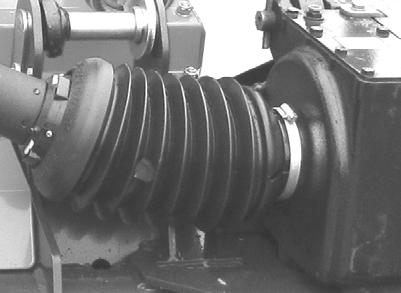
104 Maintenance 85xx model Turn the P.T.O. shaft until the grease nipples are visible. Press the nozzle of the grease gun over the grease nipple. Pump the grease gun once or twice (max.).»maintenance intervals«page 98»Lubricants«page Move the cover to the side. Turn the P.T.O. shaft until the grease nipples are visible. Press the nozzle of the grease gun over the grease nipple. Pump the grease gun once or twice (max.). Move the cover back.»maintenance intervals«page 98»Lubricants«page Turn the P.T.O. shaft until the grease nipples are visible. Press the nozzle of the grease gun over the grease nipple. Pump the grease gun once or twice (max.).»maintenance intervals«page 98»Lubricants«page Turn the P.T.O. shaft until the grease nipples are visible. Press the nozzle of the grease gun over the grease nipple. Pump the grease gun once or twice (max.).»maintenance intervals«page 98»Lubricants«page


105 Maintenance As required Connecting links, etc Press the nozzle of the grease gun over the grease nipple. Pump the grease gun once or twice (max.).»maintenance intervals«page 98»Lubricants«page 207 Spindle with springs Press the nozzle of the grease gun over the grease nipple. Pump the grease gun once or twice (max.).»maintenance intervals«page 98»Lubricants«page
106 Maintenance Service - check Cutterbar \ WARNING Safety concerning maintenance work on the cutterbar When working on the cutterbar, the tractor must be stopped and secured. This prevents the machine from suddenly starting to rotate. Failure to follow the safety instructions may result in serious injuries. When working on the cutterbar: The P.T.O. is disengaged. Lower the implement to the ground. The hydraulic controls is in neutral. The tractor engine must be stopped. The ignition key is removed. The parking brake is set. Secure the tractor to prevent it from rolling. Failure to secure the tractor to prevent it from rolling could endanger lives. Be careful when using oil Use barrier cream or protective gloves when handling oil. It will protect your hands against skin injuries. Direct contact with the oil could lead to serious skin injuries. Use the correct oil type Always use the correct oil type for the transmission. This will ensure the transmission has a long service life. Using the incorrect oil type may damage the transmission. Maintain correct oil level The maximum and minimum oil level indicators on the transmission must not be exceeded. Correct transmission oil level will ensure a long service life. Incorrect oil levels can cause the transmission to overheat, resulting in serious damage. 106
107 Maintenance Inspection - oil service Every day»maintenance intervals«page 98! The oil level for the cutterbar is checked as follows: Place the machine on a level surface. Activate the tractor hydraulics and raise the machine's cutterbar fully. Valve Close the mechanical safety valve.! 107
108 Maintenance Remove the linchpins shown here. Open the first guard. Suspend the guard in the chain as shown.! Check that the cutterbar is horizontal in the direction shown using a spirit level or similar tool. If the cutterbar is not horizontal, carry out the following: Remove the safety chain. 108
109 Maintenance Raise or lower the tractor's lift arms until the cutterbar is horizontal. Locate the oil plug on the left side of the cutterbar and remove it. With warm oil: Wait approximately 3 minutes With cold oil: Wait approximately 15 minutes. Check the oil level as shown and refill if necessary. Min. 6 mm ( 1 / 4 ) Max. 9 mm ( 3 / 8 )»Lubricants«page 207 Put the oil plug in place and tighten it fully. Close the front guard. Put the linchpins in place. 109
110 Maintenance Valve Open the mechanical safety valve. Adjust the tractor's lift arms to the height shown mm (24 3 / / 4 ) Install the safety chain.»safety chain for USA and Canada«page
111 Maintenance Gearbox \ WARNING Safety concerning maintenance work on the transmission When working on the transmission the tractor must be stopped and secured. This prevents the machine from suddenly starting to rotate. Failure to follow the safety instructions may result in serious injuries. When working on the transmission: The P.T.O. is disengaged. Lower the implement to the ground. The hydraulic controls is in neutral. The tractor engine must be stopped. The ignition key is removed. The parking brake is set. Secure the tractor to prevent it from rolling. Failure to secure the tractor to prevent it from rolling could endanger lives. Pay attention when performing oil change Use barrier cream or protective gloves when changing oil. It will protect your hands against skin injuries. Direct contact with the oil could lead to serious skin injuries. Use the correct oil type Always use the correct oil type for the transmission. This will ensure the transmission has a long service life. Using the incorrect oil type may damage the transmission. Maintain correct oil level The max. and min. oil level indicators on the transmission must not be exceeded. Correct transmission oil level will ensure a long service life. Incorrect oil levels can cause the transmission to overheat, resulting in serious damage. 111


112 Maintenance Main gear»maintenance intervals«page 98 Checking the oil level Every 80 hours of use Dipstick 80xx model The oil level is checked as follows: Remove the dipstick. Check that the oil level is up to the max indication on the dipstick. The oil level on the main gear must always be between min. and max. as shown on the dipstick. When topping up, do the following: Pour the oil through the hole where the dipstick is fitted. Put the dipstick into the transmission, then remove it again. Check that the oil level is up to the max indication on the dipstick. Repeat the procedure until the correct oil level is reached.»lubricants«page 207 Max. Min. Dipstick 85xx model The oil level is checked as follows: Remove the dipstick. Check that the oil level is up to the max indication on the dipstick. The oil level on the main gear must always be between min. and max. as shown on the dipstick. When topping up, do the following: Pour the oil through the hole where the dipstick is fitted. Put the dipstick into the transmission, then remove it again. Check that the oil level is up to the max indication on the dipstick. Repeat the procedure until the correct oil level is reached.»lubricants«page 207 Max. Min. 112
113 Maintenance Center gear Checking the oil level Every 80 hours of use Oil plug 1 Only 85xx model»maintenance intervals«page 98 The oil level is checked as follows: Remove oil plug 2. Check that the oil reaches the edge of the hole for oil plug 2. When topping up, remove oil plug 1. Fill the oil through the hole for oil plug 1. The correct oil level is reached when the oil reaches the edge of the hole for oil plug 2. Affix oil plugs 1 and 2, and then tighten them.»lubricants«page 207 Oil plug 2 113
114 Maintenance Swivel hitch Checking the oil level Every 80 hours of use»maintenance intervals«page 98 Oil plug 1 The oil level is checked as follows: The upper part of the swivel hitch Remove oil plug 2. Check that the oil is filled all the way up to the hole. When topping up, remove oil plug 1. Fill the oil through the hole for oil plug 1. The correct oil level is reached when the oil reaches the edge of the hole for oil plug 2. Affix oil plugs 1 and 2, and then tighten them.»lubricants«page 207 Oil plug 2 Oil plug 4 The lower part of the swivel hitch Remove oil plug 5. Check that the oil is filled all the way up to the hole. When topping up, remove oil plug 4. Fill the oil through the hole for oil plug 4. The correct oil level is reached when the oil reaches the edge of the hole for oil plug 5. Affix oil plugs 4 and 5, and then tighten them.»lubricants«page 207 Oil plug 5 114
115 Maintenance Blades \ WARNING Safety concerning maintenance work on the cutterbar When working on the cutterbar, the tractor must be stopped and secured. This prevents the machine from suddenly starting to rotate. Failure to follow the safety instructions may result in serious injuries. When working on the cutterbar: The P.T.O. is disengaged. Lower the implement to the ground. The hydraulic controls is in neutral. The tractor engine must be stopped. The ignition key is removed. The parking brake is set. Secure the tractor to prevent it from rolling. Failure to secure the tractor to prevent it from rolling could endanger lives. Check the machine knives on a regular basis The machine's knives must be regularly inspected. Worn or damaged knives can unbalance the rotating parts. Vibrations can cause damage to the machine. After 1 hour of use Thereafter, every day»maintenance intervals«page 98 The blades are checked as follows: Activate the tractor hydraulics and raise the machine's cutterbar to its fullest extent. 115
116 Maintenance Valve Close the mechanical safety valve.! Remove the linchpins shown here. Open the first guard. Suspend the guard in the chain as shown. 116
117 Maintenance 95 Nm +/ ft. lbs. +/- 3 Turn the cutting discs by hand until the damaged blade is in the position shown. Inspect the condition of the blades for wear. Inspect the bolt for damage or wear. If the bolt is damaged or worn, it must be changed. The minimum diameter of the bolt must not be less than φ16 mm ( 5 / 8 ).»Blades«page 167 Check that the bolt is fully tightened. If not, tighten the bolts to the indicated torque. Minimum φ16 mm (φ 5 / 8 ) Close the front guard. Put the linchpins in place. 117
118 Maintenance Valve Open the mechanical safety valve. Activate the tractor hydraulics and lower the cutting unit of the machine. 118
119 Maintenance Cutting disc \ WARNING Safety concerning maintenance work on the cutterbar When working on the cutterbar, the tractor must be stopped and secured. This prevents the machine from suddenly starting to rotate. Failure to follow the safety instructions may result in serious injuries. When working on the cutterbar: The P.T.O. is disengaged. Lower the implement to the ground. The hydraulic controls is in neutral. The tractor engine must be stopped. The ignition key is removed. The parking brake is set. Secure the tractor to prevent it from rolling. Failure to secure the tractor to prevent it from rolling could endanger lives. After 1 hour of use Thereafter, every day»maintenance intervals«page 98 The cutting discs are checked as follows: Activate the tractor hydraulics and raise the machine's cutterbar fully. 119
120 Maintenance Valve Close the mechanical safety valve.! Remove the linchpins shown here. Open the first guard. Suspend the guard in the chain as shown. 120

121 Maintenance 80 Nm +/ ft. lbs. +/- 3 Inspect the condition of the cutting discs for deformities and cracks. Tighten the cutting disc to the indicated torque. Close the front guard. Fit the linchpins. Valve Open the mechanical safety valve. 121
122 Maintenance Activate the tractor hydraulics and lower the cutting unit of the machine. 122
123 Maintenance Cone \ WARNING Safety concerning maintenance work on the cutterbar When working on the cutterbar, the tractor must be stopped and secured. This prevents the machine from suddenly starting to rotate. Failure to follow the safety instructions may result in serious injuries. When working on the cutterbar: The P.T.O. is disengaged. Lower the implement to the ground. The hydraulic controls is in neutral. The tractor engine must be stopped. The ignition key is removed. The parking brake is set. Secure the tractor to prevent it from rolling. Failure to secure the tractor to prevent it from rolling could endanger lives. External inspection Every day»maintenance intervals«page 98 An external check of the cones is carried out in the following way: Activate the tractor hydraulics and raise the machine's cutterbar fully. 123
124 Maintenance Valve Close the mechanical safety valve.! Remove the linchpins shown here. Open the first guard. Suspend the guard in the chain as shown. 124
125 Maintenance Remove dirt from the cones on both sides of the machine. Close the front guard. Put the linchpins in place. 125
126 Maintenance Valve Open the mechanical safety valve. Activate the tractor hydraulics and lower the cutting unit of the machine. 126
127 Maintenance Internal inspection Every season»maintenance intervals«page 98 An internal check of the cones is carried out in the following way: Activate the tractor hydraulics and raise the machine's cutterbar fully. Valve Close the mechanical safety valve.! Remove the linchpins shown here. Open the first guard. 127

128 Maintenance Suspend the guard in the chain as shown. Dismantle the protection around the cutterbar's transmission. Guard Remove the top cover from the cone. Clean the inside of the cone. Fit the top cover on the cone. Fit the guard around the cutterbar's transmission. Top cover Remove the top cover on the cones that are found on the opposite side of the transmission. Clean the inside of the cone. Fit the top cover on the cone. Top cover 128
129 Maintenance Close the front guard. Fit the linchpins. Valve Open the mechanical safety valve. Activate the tractor hydraulics and lower the cutting unit of the machine. 129
130 Maintenance Universal joint \ WARNING Safety concerning maintenance work on the cutterbar When working on the cutterbar, the tractor must be stopped and secured. This prevents the machine from suddenly starting to rotate. Failure to follow the safety instructions may result in serious injuries. When working on the cutterbar: The P.T.O. is disengaged. Lower the implement to the ground. The hydraulic controls is in neutral. The tractor engine must be stopped. The ignition key is removed. The parking brake is set. Secure the tractor to prevent it from rolling. Failure to secure the tractor to prevent it from rolling could endanger lives. Every month»maintenance intervals«page 98 The universal joint between the transmission and the cutterbar is checked in the following way: Activate the tractor hydraulics and raise the machine's cutterbar fully. 130
131 Maintenance Valve Close the mechanical safety valve.! Remove the linchpins shown here. Open the first guard. Suspend the guard in the chain as shown. 131
132 Maintenance Dismount the protection around the P.T.O. shaft between the transmission and the cutterbar. Guard Remove the top cover from the cone. Top cover Universal joint Inspect both universal joints for wear. Universal joint 132
133 Maintenance Bolts Check for broken or loose bolts. Replace the broken bolts. Apply Loctite 242 to the bolts. Affix the bolts and tighten to the indicated torque. 79 Nm 58 ft. lbs Loctite 242 Loctite 242 Bolts If there are loose bolts, the following procedure should be followed: Remove and clean the bolts. Apply Loctite 242 or a similar product to all bolts. Fit the bolts and tighten to the indicated torque. 79 Nm 58 ft. lbs Loctite 242 Loctite
134 Maintenance Fit the top cover on the cone. Top cover Fit the guard around the cutterbar's transmission. Guard Close the front guard. Fit the linchpins. 134
135 Maintenance Valve Open the mechanical safety valve. Activate the tractor hydraulics and lower the cutting unit of the machine. 135
136 Maintenance Stone guard and counter blade \ WARNING Safety concerning maintenance work on the cutterbar When working on the cutterbar, the tractor must be stopped and secured. This prevents the machine from suddenly starting to rotate. Failure to follow the safety instructions may result in serious injuries. When working on the cutterbar: The P.T.O. is disengaged. The hydraulic controls is in neutral. The tractor engine must be stopped. The ignition key is removed. The parking brake is set. Secure the tractor to prevent it from rolling. Failure to secure the tractor to prevent it from rolling could endanger lives. Every 40 hours of use»maintenance intervals«page 98 The stone guard and counter blade are inspected as follows: Activate the tractor hydraulics and raise the machine to its fullest extent. 136
137 Maintenance Valve Close the mechanical safety valve.! Place a suitable support under the machine's cutting unit. It is important that the machine is correctly secured with a sturdy support before work is started. Carry out a visual inspection of the machine's stone guard and counter blade for wear. Stone guards and counter blades with visible holes caused by heavy wear must be replaced immediately.»stone guard and counter blade«page
138 Maintenance Remove the support. Valve Open the mechanical safety valve. Activate the tractor hydraulics and lower the cutting unit of the machine. 138
139 Maintenance Rotor \ WARNING Safety concerning maintenance work on the cutting unit When working on the cutting unit, the tractor must be stopped and secured. This prevents the machine from suddenly starting to rotate. Failure to follow the safety instructions may result in serious injuries. When working on the cutterbar: The P.T.O. is disengaged. The hydraulic controls is in neutral. The tractor engine must be stopped. The ignition key is removed. The parking brake is set. Secure the tractor to prevent it from rolling. Failure to secure the tractor to prevent it from rolling could endanger lives. Y - fingers Every day»maintenance intervals«page 98 The machine's Y-fingers are checked as follows: Activate the tractor hydraulics and raise the machine's cutterbar fully. 139
140 Maintenance Valve Close the mechanical safety valve.! Lock plate Y-fingers Check the rotor for loose fingers. Check the lock plate by the bolt. If the lock plate is damaged or cracked, it must be changed.»y - fingers«page 184 Bolt Rotor 140
141 Maintenance Min. diameter φ9 mm. (φ 3 / 8 ). Inspect the bolt for damage or wear. If the bolt is damaged or worn, it must be changed. The minimum diameter of the bolt must not be less than φ9 mm (φ 3 / 8 ).»Y - fingers«page 184 Check that the bolt is fully tightened. If not, tighten the bolt some more. The Y-fingers should be able to move freely. Valve Open the mechanical safety valve. Activate the tractor hydraulics and lower the cutting unit of the machine. 141
142 Maintenance Transmission After 10 working hours Thereafter, every 40 hours of use»maintenance intervals«page 98 The V-belts on the rotor must be regularly checked. The V-belts for the rotor transmission is checked as follows: Activate the tractor hydraulics and lower the cutting unit of the machine. Remove the guard. Bolt 75 mm (3 ) Use a tape measure or similar to measure the springs as shown. The springs are tightened with a bolt to the measurement shown. A new machine or a newly fitted V-belt should be checked after a few hours use. V-belt 142
143 Maintenance Fit the guard. Bolt 143
144 Maintenance Friction clutch \ WARNING Safety concerning maintenance work on the transmission When working on the transmission the tractor must be stopped and secured. This prevents the machine from suddenly starting to rotate. Failure to follow the safety instructions may result in serious injuries. When working on the transmission: The P.T.O. is disengaged. Lower the implement to the ground. The hydraulic controls is in neutral. The tractor engine must be stopped. The ignition key is removed. The parking brake is set. Secure the tractor to prevent it from rolling. Failure to secure the tractor to prevent it from rolling could endanger lives. Only to be carried out after a prolonged period without use Or every season»maintenance intervals«page 98 The friction clutch is bled in the following way: 80xx model Open the protection and dismantle the lock on the friction clutch. Pull the P.T.O. shaft back, free of the drawbar. Guard 144
145 Maintenance Bolt Tighten all bolts on the friction clutch. Fit and tighten the P.T.O. shaft fully on the drawbar. 85xx model Remove the bolts Remove the cover. Bolts Bolt Tighten all bolts on the friction clutch. Bolt 145
146 Maintenance 80xx and 85xx model Remove the linchpins shown here. Open the first guard. Suspend the guard in the chain as shown. Block the cutterbar by placing a wooden block between the two cutting discs. Start the tractor and connect the tractor's P.T.O. outlet. Wooden block 146


147 Maintenance Let the friction clutch rotate freely for approx. 5 seconds at the lowest possible speed, until it is warm to the touch. Do not allow the friction clutch to rotate for more than approx. 5 seconds at a time, as this may damage the friction discs. Disconnect the P.T.O. outlet and stop the tractor. 147
148 Maintenance 80xx model Bolt Remove the P.T.O. shaft on the main gear. Loosen all the bolts on the friction clutch. Fit and tighten the P.T.O. shaft fully on the drawbar. Close the guard. Guard 85xx model Bolt Loosen all the bolts on the friction clutch. Bolt 148
149 Maintenance Affix the cover. Fit the bolts. Bolts 80xx and 85xx model Remove the wooden block from the cutter bar. Wooden block Close the front guard. Affix the linchpins shown here. 149
150 Maintenance Accumulator \ WARNING Very high amount of accumulated pressure in the accumulator Do not attempt to replace the accumulator. The accumulator contains a very high level of accumulated pressure and may only be taken apart by authorized persons. Attempting to replace the accumulator can lead to serious or fatal injury. Every season Accumulator The machine is fitted with an accumulator that can absorb excess shock from the cutting unit when the machine is in its transport mode. Pressure in the accumulator: 145 bar. (2105 psi). Inspections may only be undertaken by authorized persons. 150

151 Maintenance Wheel \ WARNING Do not drive with worn or damaged tires Do not drive with worn or damaged tires. Replace worn or damaged tires immediately. There is a high risk of accidents when driving on public roads with worn or damaged tires. After 10 working hours Thereafter, every season Bolts»Maintenance intervals«page 98 Use a suitable torque wrench adjusted to the torque shown in the table below. Place the wrench on the wheel bolts. Check all the bolts on the wheels and tighten them to the torque shown. Check the tire pressure and, if necessary, top up the tire to the pressure shown in the table below. Check tire pressure Model Tire Dimension Tire pressure bar (psi) Bolt torque Nm (ft/lbs) T T 15.0/ (37) 300 (220) 151
152 Maintenance Bolts on the transmission 85xx model only \ WARNING Safety concerning maintenance work on the transmission When working on the transmission the tractor must be stopped and secured. This prevents the machine from suddenly starting to rotate. Failure to observe the safety instructions may result in serious injuries. When working on the transmission: The tractor's PTO must be disconnected. The tool must be lowered to the ground. The tractor engine must be stopped. The ignition key must be removed. The hand brake must be activated. The tractor should be prevented from rolling. Failure to secure the tractor to prevent it from rolling could endanger lives. After 10 working hours Thereafter, every season 81 Nm / 58 ft/lb»maintenance intervals«page 98 Use a torque wrench and adjust it to the torque shown. Check all the bolts on the transmission. If the bolts are loose: Tighten the bolt to the given torque. 152
153 Maintenance Tarpaulin \ WARNING Safety concerning maintenance work on the cutting unit When working on the cutting unit, the tractor must be stopped and secured. This prevents the machine from suddenly starting to rotate. Failure to follow the safety instructions may result in serious injuries. When working on the cutterbar: The P.T.O. is disengaged. Lower the implement to the ground. The hydraulic controls is in neutral. The tractor engine must be stopped. The ignition key is removed. The parking brake is set. Secure the tractor to prevent it from rolling. Failure to secure the tractor to prevent it from rolling could endanger lives. Every month The tarpaulin and auxiliary protection around the cutterbar must be charged regularly. The tarpaulin and auxiliary protection are inspected as follows: Do a visual inspection of machine protection for holes and other damage. Protection with visible holes and other damage must be replaced immediately.»tarpaulin«page
154 Maintenance Replacement \ WARNING Safety in connection with maintenance work on the machine When working on the machine the tractor must be stopped and secured. This prevents the PTO shaft from suddenly starting to rotate. Failure to follow the safety instructions may result in serious injuries. When working on the transmission: The P.T.O. is disengaged. Lower the implement to the ground. The hydraulic controls is in neutral. The tractor engine must be stopped. The ignition key is removed. The parking brake is set. Secure the tractor to prevent it from rolling. Failure to secure the tractor to prevent it from rolling could endanger lives. Cutterbar \ WARNING Pay attention when performing oil change Use barrier cream or protective gloves when changing oil. It will protect your hands against skin injuries. Direct contact with the oil could lead to serious skin injuries. Use the correct oil type Always use the correct oil type for the transmission. This will ensure the transmission has a long service life. Using the incorrect oil type may damage the transmission. Maintain correct oil level The maximum and minimum oil level indicators on the transmission must not be exceeded. Correct transmission oil level will ensure a long service life. Incorrect oil levels can cause the transmission to overheat, resulting in serious damage. 154
155 ! Maintenance Changing oil After 10 working hours Thereafter, every 200 hours of use Or once a year»maintenance intervals«page 98 The oil in the cutterbar is changed as follows: Place a wooden block or similar under the right-hand wheel of the machine so that the machine slants slightly to the left. Activate the tractor hydraulics and raise the machine's cutterbar to its fullest extent. Valve Close the mechanical safety valve.! 155

156 Maintenance Remove the linchpins shown here. Open the first guard. Suspend the guard in the chain as shown. Locate the drain plug on the left side of the cutterbar and remove it. Let the oil flow into a suitable container. Allow the last of the oil to drip out of the cutterbar for approx minutes. Put the drain plug into the cutterbar and tighten it fully. 156
157 Maintenance! Place the machine on a level surface.! Check that the cutterbar is horizontal in the direction shown using a spirit level or similar tool. If the cutterbar is not horizontal, do the following: Remove the safety chain. Raise or lower the tractor's lift arms until the cutterbar is horizontal. 157
 Pints (US) (approx.) Pints (Imp.) (Approx.) 8028T 3.6 7.6 6.3 8032T 4.")
»Lubricants«page 207 Fit the oil plug and tighten it fully.")
158 Maintenance Remove the oil plug. Fill up with the new oil until the oil level is as shown. Model Liter (approx.) Pints (US) (approx.) Pints (Imp.) (Approx.) 8028T T T-8536T T Min. 6 mm ( 1 / 4 ) Max. 9 mm ( 3 / 8 )»Lubricants«page 207 Fit the oil plug and tighten it fully. Close the front guard. Fit the linchpins. 158
159 Maintenance Valve Open the mechanical safety valve. Adjust the tractor's lift arms to the height shown mm (24 3 / / 4 ) Install the safety chain.»safety chain for USA and Canada«page
160 Maintenance Transmission \ WARNING Safety concerning maintenance work on the transmission When working on the transmission the tractor must be stopped and secured. This prevents the machine from suddenly starting to rotate. Failure to follow the safety instructions may result in serious injuries. When working on the transmission: The P.T.O. is disengaged. Lower the implement to the ground. The hydraulic controls is in neutral. The tractor engine must be stopped. The ignition key is removed. The parking brake is set. Secure the tractor to prevent it from rolling. Failure to secure the tractor to prevent it from rolling could endanger lives. Pay attention when performing oil change Use barrier cream or protective gloves when changing oil. It will protect your hands against skin injuries. Direct contact with the oil could lead to serious skin injuries. Use the correct oil type Always use the correct oil type for the transmission. This will ensure the transmission has a long service life. Using the incorrect oil type may damage the transmission. Maintain correct oil level The max. and min. oil level indicators on the transmission must not be exceeded. Correct transmission oil level will ensure a long service life. Incorrect oil levels can cause the transmission to overheat, resulting in serious damage. 160
161 Maintenance Main gear Changing oil After 10 working hours Thereafter, every season»maintenance intervals«page 98 Oil amount when changing oil: Liters (approx.) Pints (US) (approx.) Pints (Imp.) (approx.) xx model The oil is changed as follows: Remove the guard. Bolt Remove the oil plug. Let the oil flow into a suitable container. Allow the last of the oil to drip out of the transmission for approx minutes. Fit the oil plug and tighten it. Oil plug 161
162 Maintenance Dipstick Remove the dipstick. Pour the new oil through the hole where the dipstick is fitted. Put the dipstick into the transmission, then remove it again. Check that the oil level is up to the max indication on the dipstick. Repeat the procedure until the correct oil level is reached. The oil level on the main gear must always be between min. and max. as shown on the dipstick.»lubricants«page 207 Max. Min. Fit the guard. Bolt 162
163 Maintenance 85xx model The oil is changed as follows: Remove the guard. Bolt Remove the oil plug. Let the oil flow into a suitable container. Allow the last of the oil to drip out of the transmission for approx minutes. Fit the oil plug and tighten it. Oil plug Dipstick Remove the dipstick. Pour the new oil through the hole where the dipstick is fitted. Put the dipstick into the transmission, then remove it again. Check that the oil level is up to the max indication on the dipstick. Repeat the procedure until the correct oil level is reached. The oil level on the main gear must always be between min. and max. as shown on the dipstick.»lubricants«page 207 Max. Min. 163
164 Maintenance Affix the guard. Bolt 164
 Pints (US) (approx.) Pints (Imp.) (approx.) 2.0 4.2 3.5 The oil is changed as follows: Remove oil plug 3. Let the oil flow into a suitable container.")

165 Maintenance Center gear Changing oil After 10 working hours Thereafter, every season Only 85xx model»maintenance intervals«page 98 Oil amount when changing oil: Liters (approx.) Pints (US) (approx.) Pints (Imp.) (approx.) The oil is changed as follows: Remove oil plug 3. Let the oil flow into a suitable container. Allow the last of the oil to drip out of the transmission for approx minutes. Fit oil plug 3 and tighten it. Oil plug 3 Oil plug 1 Remove oil plug 1 and 2. Fill the new oil through the hole for oil plug 1. The correct oil level is reached when the oil reaches the edge of the hole for oil plug 2. Affix oil plugs 1 and 2, and then tighten them.»lubricants«page 207 Oil plug 2 165
166 Maintenance Swivel hitch Changing oil After 10 working hours Thereafter, every season Oil plug 2 Oil plug 1 The upper part of the swivel hitch Oil amount when changing oil: Liter (approx.) Pints (US) (approx.) Pints (Imp.) (approx.) Oil plug 3 The oil is changed as follows: Remove oil plug 3. Let the oil flow into a suitable container. Allow the last of the oil to drip out of the transmission for approx minutes. Put oil plug 3 in place and tighten it. Remove oil plug 1 and 2. Fill the new oil through the hole for oil plug 1. The correct oil level is reached when the oil reaches the edge of the hole for oil plug 2. Affix oil plugs 1 and 2, and then tighten them.»lubricants«page 207 Oil plug 4 Oil plug 5 The lower part of the swivel hitch»maintenance intervals«page 98 Oil amount when changing oil: Liter (approx.) Pints (US) (approx.) Pints (Imp.) (approx.) Oil plug 6 The oil is changed as follows: Remove oil plug 6. Let the oil flow into a suitable container. Allow the last of the oil to drip out of the transmission for approx minutes. Put oil plug 6 in place and tighten it. Remove oil plug 4 and 5. Fill the new oil through the hole for oil plug 5. The correct oil level is reached when the oil reaches the edge of the hole for oil plug 5. Put oil plug 4 in place and tighten it»lubricants«page
167 Maintenance Blades \ WARNING Safety concerning maintenance work on the cutterbar When working on the cutterbar, the tractor must be stopped and secured. This prevents the machine from suddenly starting to rotate. Failure to follow the safety instructions may result in serious injuries. When working on the cutterbar: The P.T.O. is disengaged. Lower the implement to the ground. The hydraulic controls is in neutral. The tractor engine must be stopped. The ignition key is removed. The parking brake is set. Secure the tractor to prevent it from rolling. Failure to secure the tractor to prevent it from rolling could endanger lives. Check the machine knives on a regular basis The machine's knives must be regularly inspected. Worn or damaged knives can unbalance the rotating parts. Vibrations can cause damage to the machine. As required»maintenance intervals«page 98 The blades are replaced as follows: Activate the tractor hydraulics and raise the machine's cutterbar fully. 167
168 Maintenance Valve Close the mechanical safety valve.! Remove the linchpins shown here. Open the first guard. Suspend the guard in the chain as shown. 168
. Replace the blade and affix the bolt. Use a torque wrench to tighten the bolt to the torque shown.")
169 Maintenance 95 Nm +/ ft. lbs. +/- 3 Turn the cutting discs by hand until the damaged blade is in the position shown. Remove the bolt. The minimum diameter of the bolt must not be less than φ16 mm ( 5 / 8 ). Replace the blade and affix the bolt. Use a torque wrench to tighten the bolt to the torque shown. Minimum φ16 mm (φ 5 / 8 ) 169
170 Maintenance Close the front guard. Fit the linchpins. Valve Open the mechanical safety valve. Activate the tractor hydraulics and lower the cutting unit of the machine. 170
171 Maintenance Cutting disc \ WARNING Safety concerning maintenance work on the cutterbar When working on the cutterbar, the tractor must be stopped and secured. This prevents the machine from suddenly starting to rotate. Failure to follow the safety instructions may result in serious injuries. When working on the cutterbar: The P.T.O. is disengaged. Lower the implement to the ground. The hydraulic controls is in neutral. The tractor engine must be stopped. The ignition key is removed. The parking brake is set. Secure the tractor to prevent it from rolling. Failure to secure the tractor to prevent it from rolling could endanger lives. As required»maintenance intervals«page 98 The cutting discs are replaced as follows: Activate the tractor hydraulics and raise the machine's cutterbar fully. 171
172 Maintenance Valve Close the mechanical safety valve.! Remove the linchpins shown here. Open the first guard. Suspend the guard in the chain as shown. 172
 Affix the blade and bolt on the new cutting disc. Use a torque wrench to tighten the nut to the torque shown.")
173 Maintenance Dismantle the cutting disc. Remove the bolt and blade from the cutting disc. 95 Nm +/- 5 (70 ft. lbs. +/- 4) Affix the blade and bolt on the new cutting disc. Use a torque wrench to tighten the nut to the torque shown. 173
174 Maintenance Loctite Nm +/- 5 (59 ft. lbs. +/- 4) Apply Loctite 242 or a similar product to all bolts. Affix the cutting disc on the cutterbar. Use a torque wrench to tighten the bolt to the torque shown. Loctite Bolt Close the front guard. Fit the linchpins. Valve Open the mechanical safety valve. 174
175 Maintenance Activate the tractor hydraulics and lower the cutting unit of the machine. 175
176 Maintenance Universal joint \ WARNING Safety concerning maintenance work on the cutterbar When working on the cutterbar, the tractor must be stopped and secured. This prevents the machine from suddenly starting to rotate. Failure to follow the safety instructions may result in serious injuries. When working on the cutterbar: The P.T.O. is disengaged. The hydraulic controls is in neutral. The tractor engine must be stopped. The ignition key is removed. The parking brake is set. Secure the tractor to prevent it from rolling. Failure to secure the tractor to prevent it from rolling could endanger lives. As required»maintenance intervals«page 98 The P.T.O. shaft is changed as follows: Activate the tractor hydraulics and raise the machine's cutterbar fully. 176
177 Maintenance Valve Close the mechanical safety valve.! Remove the linchpins shown here. Open the first guard. Suspend the guard in the chain as shown. 177
178 Maintenance Dismount the protection around the P.T.O. shaft between the transmission and the cutterbar. Guard Remove the top cover from the cone. Top cover Bolts P.T.O. shaft Remove the bolts and replace the P.T.O. shaft. Clean the bolts. Apply Loctite 242 or a similar product to all bolts. Fit the bolts and tighten to the indicated torque. 79 Nm 58 ft. lbs Loctite 242 Loctite
179 Maintenance Fit the top cover on the cone. Top cover Fit the guard around the cutterbar's transmission. Guard Close the front guard. Put the linchpins in place. 179
180 Maintenance Valve Open the mechanical safety valve. Activate the tractor hydraulics and lower the cutting unit of the machine. 180
181 Maintenance Stone guard and counter blade \ WARNING Safety concerning maintenance work on the cutterbar When working on the cutterbar, the tractor must be stopped and secured. This prevents the machine from suddenly starting to rotate. Failure to follow the safety instructions may result in serious injuries. When working on the cutterbar: The P.T.O. is disengaged. The hydraulic controls is in neutral. The tractor engine must be stopped. The ignition key is removed. The parking brake is set. Secure the tractor to prevent it from rolling. Failure to secure the tractor to prevent it from rolling could endanger lives. As required»maintenance intervals«page 98 The stone guard and counter blade are changed as follows: Activate the tractor hydraulics and raise the machine fully. 181

182 Maintenance Valve Close the mechanical safety valve.! Place a suitable support under the machine's cutting unit. It is important that the machine is correctly secured with a sturdy support before work is started. Remove the worn stone guard and counter blade. 182

183 Maintenance Fit the new stone guard and counter blade. Stone guards and counter blades with visible holes caused by heavy wear must be replaced immediately. Remove the support. Valve Open the mechanical safety valve. Activate the tractor hydraulics and lower the cutting unit of the machine. 183
184 Maintenance Rotor \ WARNING Safety concerning maintenance work on the cutting unit When working on the cutting unit, the tractor must be stopped and secured. This prevents the machine from suddenly starting to rotate. Failure to follow the safety instructions may result in serious injuries. When working on the cutterbar: The P.T.O. is disengaged. The hydraulic controls is in neutral. The tractor engine must be stopped. The ignition key is removed. The parking brake is set. Secure the tractor to prevent it from rolling. Failure to secure the tractor to prevent it from rolling could endanger lives. Y - fingers As required»maintenance intervals«page 98 The machine's Y-fingers are replaced as follows: Activate the tractor hydraulics and raise the machine fully. 184
. Inspect the bolt for wear. The minimum diameter of the bolt must not be less than φ9 mm (φ 3 / 8 ).")
185 Maintenance Valve Close the mechanical safety valve.! Lock plate Y-fingers Remove the nut on the bolt. Remove the bolt and the lock plate and replace the damaged Y- finger. Bolt Rotor Min. diameter φ9 mm. (φ 3 / 8 ). Inspect the bolt for wear. The minimum diameter of the bolt must not be less than φ9 mm (φ 3 / 8 ). If the diameter of the bolt is less than φ9 mm (φ 3 / 8 ) in the worn areas, it must be replaced. Fit the bolt with the lock plate and Y-fingers. Tighten the bolt. The Y-fingers should be able to move freely. 185
186 Maintenance Valve Open the mechanical safety valve. Activate the tractor hydraulics and lower the cutting unit of the machine. 186
187 Maintenance Transmission As required»maintenance intervals«page 98 The V-belts are changed in the following way: Activate the tractor hydraulics and lower the cutting unit of the machine. Remove the guard. Bolt Bolt Completely loosen the bolt on the spring. Remove the V-belts. Put the new V-belts in place. V-belt 187
 Fit the guard.")
188 Maintenance Tighten the springs to the measurement shown. 75 mm (3 ) Fit the guard. Bolt 188
189 Maintenance Friction clutch \ WARNING Safety concerning maintenance work on the transmission When working on the transmission the tractor must be stopped and secured. This prevents the machine from suddenly starting to rotate. Failure to follow the safety instructions may result in serious injuries. When working on the transmission: The P.T.O. is disengaged. Lower the implement to the ground. The hydraulic controls is in neutral. The tractor engine must be stopped. The ignition key is removed. The parking brake is set. Secure the tractor to prevent it from rolling. Failure to secure the tractor to prevent it from rolling could endanger lives. As required»maintenance intervals«page 98 80xx model The friction discs on the friction clutch are changed as follows: Open the protection and dismantle the lock on the friction clutch. Pull the P.T.O. shaft back, free of the drawbar. Guard 189
190 Maintenance Bolt Tighten all bolts on the friction clutch. Use pointed tool Use a screwdriver or similar pointed tool to force the circlip out of the friction clutch. Take the friction clutch apart and replace the friction discs. Assemble and affix the friction clutch. Affix the circlip. Circlip Bolt Loosen all the bolts on the friction clutch. The setting for the clutch can not be adjusted. 190
191 Maintenance Fit and tighten the P.T.O. shaft fully on the drawbar. Close the guard. Guard 85xx model Remove the bolts. Remove the cover. Bolts Bolt Remove the lock on the friction clutch and push the friction clutch off the shaft. Bolt 191

192 Maintenance Bolt Tighten all bolts on the friction clutch. Use pointed tool Use a screwdriver or similar pointed tool to force the circlip out of the friction clutch. Take the friction clutch apart and replace the friction discs. Assemble and affix the friction clutch. Fit the circlip. Circlip Bolt Loosen all the bolts on the friction clutch. The setting for the clutch can not be adjusted. 192
193 Maintenance Bolt Attach the friction clutch on the shaft and attach and fasten the lock on the friction clutch. Bolt Fit the cover. Fit the bolts. Bolts 193
194 Maintenance Accumulator \ WARNING Very high amount of accumulated pressure in the accumulator Do not attempt to replace the accumulator. The accumulator contains a very high level of accumulated pressure and may only be taken apart by authorized persons. Attempting to replace the accumulator can lead to serious or fatal injury. As required Accumulator The machine is fitted with an accumulator that can absorb excess shock from the cutting unit when the machine is in its transport mode. Pressure in the accumulator: 145 bar. (2105 psi) The accumulator may only be replaced by authorized service personnel. 194

195 Maintenance Tarpaulin \ WARNING Safety concerning maintenance work on the cutting unit When working on the cutting unit, the tractor must be stopped and secured. This prevents the machine from suddenly starting to rotate. Failure to follow the safety instructions may result in serious injuries. When working on the cutterbar: The P.T.O. is disengaged. Lower the implement to the ground. The hydraulic controls is in neutral. The tractor engine must be stopped. The ignition key is removed. The parking brake is set. Secure the tractor to prevent it from rolling. Failure to secure the tractor to prevent it from rolling could endanger lives. Every month The tarpaulin and auxiliary protection around the cutterbar must be charged regularly. Replacement of a damaged tarpaulin and auxiliary protection is done as follows: Remove the machine's protection. Replace the damages parts. Attach the machine's protection. Make sure that the machine's protection is correctly attached. 195


196 Extra equipment Extra equipment Spreading device Spreading device The machine can be fitted with a flip-over spreading device that ensures a perfect spreading of the crop. The spreading device is simple to use and can be swung round when in use. 196
 80 mm (3 ) High skids are recommended for uneven fields with lots of stones or molehills.")
 skids fitted 79 100 mm (4 ) or more»long stubble height«+ 80 mm (3 ) skids fitted 79 * Standard Throwing wings Fitting throwing wings is recommended to rectify any stripe problems with spring")
197 Extra equipment High skids The machine can be fitted with high skids if a higher stubble height is required. The skids are available in the following heights: 40 mm (1 9 /16 ) 80 mm (3 ) High skids are recommended for uneven fields with lots of stones or molehills. High skids Stubble height Setting - see chapter: Page mm (1 3 / / 8 )»Long stubble height«+ 20 mm ( 3 / 4 ) skids* fitted mm (2-4 5 / 16 )»Long stubble height«+ 40 mm (1 9 / 16 ) skids fitted mm (4 ) or more»long stubble height«+ 80 mm (3 ) skids fitted 79 * Standard Throwing wings Fitting throwing wings is recommended to rectify any stripe problems with spring crops, caused by grass blocking the cutting discs. The throwing wings are specifically made for right and left turning cutting discs. Throwing wings 197
198 Extra equipment Rotor RPM 500 RPM For mowing whole crop The machine can be fitted with a set consisting of a V-belt pulley and 3 V-belt parts, which reduces the speed of the machine's rotor to 500 RPM. It is recommended that this extra equipment be used for cutting whole crops.»rotor«page RPM When harvesting difficult crops The machine can be fitted with a set consisting of a V-belt pulley and 3 V-belt parts, which reduces the speed of the machine's rotor to 1015 RPM. It is recommended that this extra equipment be used for cutting whole crops.»rotor«page


199 Extra equipment Weights Weights The machine can be fitted with weights that are mounted on the machine's wheels. Weights are used on hilly land to stabilize the machine. P.T.O. shaft 8 or 21 splines The machine can be fitted with P.T.O. shafts with either 8 or 21 splines. Hour counter Hour counter Reset 2 sec. kverneland group The machine can be fitted with an hour counter which has the following functions: Total time, which records the total number of hours the machine has run throughout its service life. Trip function, which can be reset to record the individual hours the machine has been running for a particular period. The hour counter only records time when the P.T.O. shaft is coupled to the machine. The hour counter also has the following features: A light function on both displays so the hour counter can be read in the dark. There is need for an external power source as its own power requirements are generated when the P.T.O. shaft is coupled. 199

200 Extra equipment Chain for locking the lift arms A chain is available as extra equipment to prevent the tractor's lift arms from lowering. The chain is fitted between the highest point on the tractor and one of the lift arms. Chain 200
201 Troubleshooting Troubleshooting Electric and hydraulic system Fault Possible cause Solution Page Hydraulic system The machine's hydraulic functions do not work Check that the hydraulic hoses are correctly connected to the tractor's hydraulic outlet Make sure that the tractor hydraulics are engaged The machine's hydraulic functions seem sluggish Insufficient amount of oil from the tractor Cutterbar Fault Possible cause Solution Page The machine is sloping to the rear during mowing There is too much downward pressure on the cutterbar Adjust the springs 82 Uneven stubble Driving too slowly Increase speed 32 The tractor RPM on the P.T.O. is too low The blades are blunt or individual blades are missing Check RPM Turn or replace the blades The machine is not correctly balanced Adjust the springs 82 Stripes in the stubble 1 The cutterbar is not correctly angled for the crop in question Adjust the angle of the cutterbar The cutterbar is fitted with high skids 3 Remove the high skids Note! The field must be free of stones 77 Build up of crop on the cutting discs Increase speed Affix throwing wings 3 on the cutting discs 197 Set the rotor to 900 RPM 73 Uneven swathes The rotor's RPM is too low Set the rotor to 900 RPM 73 Incorrect setting of the deflector plate Adjust the deflector plates 76 The cutting unit receives violent shocks during road transport The machine's accumulator has too little pressure or is defective Check or replace the accumulator The safety valve is closed The safety valve must be open
202 Troubleshooting Fault Possible cause Solution Page Conditioning too weak Too much distance between the conditioner plate and the rotor Adjust the conditioner plate 72 The rotor's RPM is too low Set the rotor to 900 RPM 73 The rotor V-belts are not tightened sufficiently Check the V-belts 142 The rotor V-belts are worn Replace the V-belts 187 Blockage of the flow of crop through the machine The cutterbar gets abnormally warm The crop glides underneath the rotor The rotor V-belts are not tightened sufficiently Check the V-belts The rotor V-belts are worn Replace the V-belts 187 The conditioner plate is too close to the rotor Change the setting of the conditioner plate Too much oil in the cutterbar Inspect the oil level in the cutterbar 107 Wrong oil type Change to the correct oil type 207 The throwing wings 3 are not mounted on the cutting discs Affix throwing wings The throwing wings 3 are worn Replace the throwing wings P.T.O. shaft Fault Possible cause Solution Page The friction clutch on the P.T.O. shaft becomes abnormally warm The RPM on the P.T.O. shaft is too low Check RPM 32 The friction discs in the coupling are worn Check the friction discs in the coupling 144 Replace the friction discs in the clutch 189 Insufficient transferal of power/torque to the machine The friction discs in the coupling are worn Check the friction discs in the coupling 144 Replace the friction discs in the clutch Problems with stripes are more likely to occur when mowing short, strong, spring crops in less than ideal weather conditions. Always begin by checking that the blades on the cutting discs are sharp. 2 May only be carried out by authorized service personnel. 3 Extra equipment - Page
203 Warranty Warranty Guidelines for warranty The warranty period for our product is 12 months from the date of purchase. The warranty does not include the parts subject to wear. Warranty claims can be made with Kverneland warranty application which must be filled out by your local Kverneland dealer where your machine/equipment was purchased. No liability is accepted for any damage that may arise We are not liable for compensation for any damage not arising from the machine/equipment itself. This also includes damage arising from incorrect usage of the machine/equipment. Therefore, read this instruction manual before putting the machine/ equipment to use. Furthermore, always check that the machine/ equipment works correctly before and during use. 203
204 Disposal Disposal When the machine reaches the end of its service life, it must be disposed of in the correct way. Observe the following: Metal parts Take usable parts to an authorized recycling plant. Larger scrap parts must be taken to an authorized wrecker where they can be processed in accordance with applicable regulations. Rubber parts Take usable parts to an authorized recycling plant where they can be processed in accordance with applicable regulations. Plastic Take usable parts to an authorized recycling plant where they can be processed in accordance with applicable regulations. Hydraulic oil and lubricants The machine shall be emptied of oil and lubricants. Used oil must be taken to a wrecker where it can be processed in accordance with applicable regulations. Electronic parts Take usable parts to an authorized recycling plant where they can be processed in accordance with current regulations. 204

205 EU Declaration of Conformity Declaration of Conformity EU Directive 2006/ 42/EC We: Kverneland Group Kerteminde AS Taarupstrandvej 25 DK Kerteminde Denmark hereby declare under our sole responsibility that the following product: 8028T T T 8536T T and ancillary equipment CE plate and type plate Applicable as from machine No: KT to which the declaration refers complies with the fundamental safety requirements set out in EU Directive 2006/42/EC. To fulfill the appropriate safety requirements under the terms of the EU Directive, the following standards have been applied: DIN EN ISO :2003 DIN EN ISO :2003 DIN EN ISO :2012 DIN :1998 Claus Udengaard Thomsen Kverneland Group Kerteminde AS Kerteminde - Denmark Claus Udengaard Thomsen EU authorized representative 205
206 Notes Notes 206
207 Technical information Technical information Conversion table Basic unit: SI - unit Conversion figures: Length 1 m 39.4 in = 3.3 ft = 1.1 yd = miles (US) Area 1 m yd 2 = 10.8 ft 2 = acre = ha Volume 1 dm 3 (1 l) 61 in 3 = ft 3 = 0.22 gallon (lmp) = 0.26 gallon (US) Speed 1 m/sec 3.6 km/h = 2.24 mph = 3.28 ft/sec Power 1 N 0.10 kp = 0.22 lbf Effect 1 kw 1.36 hp = 102 kpm/sec Mass 1 kg 2.2 lbs = cwt = 35 oz Torque moment 1 Nm kpm = 8.8 lb-in = 0.74 ft. lbs. Pressure 1 bar 0.01 atm. (kp/cm 2 ) = 0.14 psi RPM min -1 = revolutions / min = RPM Lubricants Only check the oil level when there is a visible loss of oil while the machine is level. Transmission oil and lubricant must meet the following requirements Specification Transmission oil Lubricant SAE J W-90 NLGI GC/LB 2 API GL-4 Examples: KUBOTA Heavy Duty 80W-90 Transmission KUBOTA Polyurea Grease 207

208 Technical information Torque moment \ WARNING Use the correct torque Fasten the screws, nuts and bolts using the indicated torque. Otherwise, this may result in damaging the machine and cause serious injury or death. Specification of quality class Note the quality class for screws, nuts and bolts. Note the size of screw, nut and bolt and find the corresponding torque in the table. Tighten screws, nuts and bolts to the indicated values, provided that no other value is indicated. Tightening torque for grade 8.8 black and/or galvanized and ungreased bolts when tightened on a smooth surface or a plain washer Thread dia. mm Nm ft/lbs The tables above apply unless otherwise indicated in the instruction manual for this machine. 208
DM Operator s manual Translated from the original operator s manual Revision 02 Date printed Index
 DM 5032-5040 Operator s manual Translated from the original operator s manual Revision 02 Date printed 01.2015 Language EN-US Machine number KT453155 Document number A132336640 Index 2015-01 Machine identification
4332LR LR CR
 4332LR - 4336LR - 4336CR Operator's Manual Translated from the original instruction manual Version 2012-03 Date printed 03.2012 Language EN Machine no. KT422977 Document no. 90015106EN Index number 2012-03
DM Operator s manual Translated from the original operator s manual Revision 01 Date printed
 DM 1017-1022 - 1024 Operator s manual Translated from the original operator s manual Revision 01 Date printed 08.2014 Language EN-US Machine number KT449674 Document number A132186140 Index 2014-09 Machine
Extra Operating manual Translated from the original instruction manual Revision 01 Date printed Language.
 Extra 532-540 Operating manual Translated from the original instruction manual Revision 01 Date printed 04.2014 Language EN Machine number KT447406 Document number A132101500 Index 2014-03 Machine identification
2624M M M
 2624M - 2628M - 2632M Operating manual Translated from the original instruction manual Revision 02 Date printed 11.2014 Language EN-EU Machine number KT449178 Document number A132575940 Index 2014-11 Machine
Chopper SE
 Chopper SE4235-4280-4325 Operator s manual Translation of original operator s manual Edition 09.2015 Date of print 12.2015 Language EN From machine number MACHOxx105462 Model Document number A137258840
Chopper SE
 Chopper SE3155-3185-3200-3230 Operator s manual Translation of original operator s manual Edition 09.2015 Date of print 12.2015 Language EN From machine number MACHOxx105426 Model Document number A137249940
W & A 12 ROW TOP LEVELING STACKER LEVEL BANDER
 W & A 12 ROW TOP LEVELING STACKER LEVEL BANDER NO. 3640 OPERATOR S MANUAL TO THE OWNER: Congratulations on your purchase of a new W & A Top Leveling Stacker Level Bander. Your selection is an indication
Operator s ManualMOWERS
 Operator s ManualMOWERS ATTENTION Carefully read this manual before using the machine M48-S M48-A M60-S M60-A M72-S M72-A M84-S M84-A March 2009 page 1 page 2 Belco Resources Equipment PO Box 8164 Rocky
SERIES 04 DIAMOND HARROW PRODUCT MANUAL FOR SECTIONS & SETS
 SERIES 04 DIAMOND HARROW PRODUCT MANUAL FOR SECTIONS & SETS TABLE OF CONTENTS Welcome Note 4 Safety 5 Usage Information 7 Normal Packaging 9 Assembly Instructions 10 Operating Instructions 13 Series 04
610 BUSHEL MANURE SPREADER
 610 BUSHEL MANURE SPREADER RODA MANUFACTURING 1008 LOCUST ST. HULL, IA. 51239 Art s-way Manufacturing 712-439-2366 Co., Inc. Hwy 9 West - PO Box 288 WWW.RODAMFG.COM Armstrong, IA. 50514 U.S.A 2 INTRODUCTION
W & A 12 ROW TOP LEVELING STACKER LEVEL BANDER
 W & A 12 ROW TOP LEVELING STACKER LEVEL BANDER NO. 3640 OPERATOR S MANUAL TO THE OWNER: Congratulations on your purchase of a new W & A Top Leveling Stacker Level Bander. Your selection is an indication
LOG SPLITTER. Heavy Duty PTO Driven. Owners Illustrated Instruction Book & Parts List
 LOG SPLITTER Heavy Duty PTO Driven Owners Illustrated Instruction Book & Parts List Grovebury Road, Leighton Buzzard, Bedfordshire. LU7 4UX. UK. Tel:01525 375157. Fax:01525 385222. Email: enquires@brownsagricultural.co.uk
OPERATORS MANUAL FOR KAFURTER ROTARY TOPPERS MODELS: TP110, TP140, TP160, TP170
 OPERATORS MANUAL FOR KAFURTER ROTARY TOPPERS MODELS: TP110, TP140, TP160, TP170 SAFETY WARNING: Do not use or operate this this manual and assembly instructions (where applicable) has been read and understood.
Predelivery Instructions
 PINK Predelivery Instructions SR5030 Split-Row Planter Manufacturing, Inc. P.O. Box 5060 Salina, Kansas 67402-5060! Read this manual entirely. When you see this symbol, the subsequent instructions and
Concrete Mixer DBM 750
 Concrete Mixer DBM 750 OPERATING INSTRUCTIONS AND SPARE PARTS READ CAREFULLY BEFORE OPERATING M ACHINE August 2006 Concrete Mixer Type DBM750 Technical data: Mixing capacity 0.75 m3 Container diameter:
Operator's manual Original operator's manual Edition Date of print
 9032 Operator's manual Original operator's manual Edition 06.2014 Date of print 10.2014 Language EN-EU Machine number VF65892140 Model VF6589 Document number VF16645560.EN-EU Machine identification In
ASSEMBLY, USE AND MAINTENANCE ST 780 H ROTARY TEDDER
 ASSEMBLY, USE AND MAINTENANCE ST 780 H ROTARY TEDDER 05/2006 WARRANTY SITREX spa warrants new SITREX machinery at the time of delivery to the original purchaser to be free from defects in material and
Agricultural tractor Note: It is recommended that you read the Supporting Information page before you read this factsheet.
 Agricultural tractor Note: It is recommended that you read the Supporting Information page before you read this factsheet. Preparation Agricultural tractors, as the name suggests, are machines originally
9542 / Operator's manual Original operator's manual Edition Date of print
 9542 / 9546 Operator's manual Original operator's manual Edition 03.2015 Date of print 06.2015 Language EN-EU Machine number VF658210550 / VF65835400 Model VF6582 / VF6583 Document number A131023900 Machine
Auto-Locking Trailer Coupler
 Auto-Locking Trailer Coupler 7-Ton Capacity Owner s Manual WARNING: Read carefully and understand all ASSEMBLY AND OPERATION INSTRUCTIONS before operating. Failure to follow the safety rules and other
MK AUGERS POWER SWING KIT ASSEMBLY & OPERATION MANUAL
 MK AUGERS POWER SWING KIT ASSEMBLY & OPERATION MANUAL Read this manual before using product. Failure to follow instructions and safety precautions can result in serious injury, death, or property damage.
6.0 Vehicles and machinery
 Code of Practice for Preventing Injury and Occupational Ill Health in Agriculture 6.0 Vehicles and machinery 6.1. Risk assessment Farm vehicles and machinery account for the highest proportion of farm
Assembly and Maintenance Manual Type ASNU
 Assembly and Maintenance Manual Type ASNU Hatschekstr.36 69126 Heidelberg Germany Tel +49(0)6221 30470 Fax +49(0)6221 304731 info@stieber.de www.stieber.de Date of issue: 30.05.2018 GB Revision: 0 U:\EngUsers\!ProduktDoku\1AAA_Einbauerklaerung_Wartungsanleitung_Konformitaetserklaerung\1AAA_Wartungsanleitungen\Orginal_Worddatei\_ASNU.docx
ENGINE DRIVEN ROTARY MOWER
 ENGINE DRIVEN ROTARY MOWER Operation, Service & Parts Manual For Models ERM-413, 416, & 617 April 2009 Form: ERMHydMower TABLE OF CONTENTS SECTION DESCRIPTION...PAGE 1 Introduction... 1 2 Preparation...2
Northern Sales & Distribution Centre
 User Manual Industrial Door Northern Sales & Distribution Centre The Door Centre, Discovery Park, Crossley Road, Stockport, SK4 5BW /indupart /indupart /indupart /company/indupart-ltd Foreword This user
EXTRΔ Mounted Plain Disc Mowers
 EXTRΔ 117-122-124-228-232 Mounted Plain Disc Mowers Cutting Performance in New Dimensions Fully welded cutterbar for a very strong construction. Even number of contra-rotating discs for improved overlap.
48 in. DELUXE ALUMINUM CARGO CARRIER WITH RAMP
 48 in. DELUXE ALUMINUM CARGO CARRIER WITH RAMP OWNER S MANUAL WARNING: Read carefully and understand all ASSEMBLY AND OPERATION INSTRUCTIONS before operating. Failure to follow the safety rules and other
Directions for use VIBRO FLEX 7400
 Directions for use VIBRO FLEX 7400 Contents Introduction... 3 Identification... 3 Explanation of symbols... 4 Safety... 5 General safety advice... 5 Coupling and uncoupling... 5 Three-point hitch or linkage...
25 BUSHEL MANURE SPREADER
 25 BUSHEL MANURE SPREADER RODA MANUFACTURING 338 MAIN ST. HULL, IA. 51239 Art s-way Manufacturing 712-439-2366 Co., Inc. Hwy 9 West - PO Box 288 WWW.RODAMFG.COM Armstrong, IA. 50514 U.S.A 2 INTRODUCTION
Hydraulic PTO Flow Device
 Safety, Operation, and Maintenance Manual WARNING Improper use of this tool can result in serious bodily injury This manual contains important information about product function and safety. Please read
Operator's Manual. VC-60 & VC-60 Plus Harper Industries, Inc. 7/03 Part No
 Operator's Manual VC-60 & VC-60 Plus 2003 Harper Industries, Inc. 7/03 Part No. 970066 Thank you for purchasing a Harper/Goossen Verti-Cutter. As with all Harper/Goossen products, the Harper/Goossen Verti-Cutter
Hydraulic Immediate Need Power Pack
 Safety, Operation, and Maintenance Manual WARNING Improper use of this tool can result in serious bodily injury This manual contains important information about product function and safety. Please read
LOG CHOP. Hydraulic Wood Guillotine. Owners Illustrated Instruction Book & Parts List
 LOG CHOP Hydraulic Wood Guillotine Owners Illustrated Instruction Book & Parts List Grovebury Road, Leighton Buzzard, Bedfordshire. LU7 4UX. UK. Tel:01525 375157. Fax:01525 385222. Email: enquires@brownsagricultural.co.uk
Auto-Locking Pintle Hook
 Auto-Locking Pintle Hook 7-Ton Capacity Owner s Manual WARNING: Read carefully and understand all ASSEMBLY AND OPERATION INSTRUCTIONS before operating. Failure to follow the safety rules and other basic
THE VERSA-DRILL 3-POINT MOUNTED NO-TILL DRILL; ATV-PULL TYPE DRILLS
 THE VERSA-DRILL 3-POINT MOUNTED NO-TILL DRILL; ATV-PULL TYPE DRILLS Models KVGT-489, KVGT-728, KVGA-489 170 West 600 North Shelbyville, Indiana 46176 800.458.9129 www.kascomfg.com THANK YOU! You have invested
Owner's/Installation Manual
 Owner's/Installation Manual Power Management Module (PMM) and Starter Kit NOTE: The starter kit must be purchased and installed prior to individual PMM usage. Model Numbers: 00686-0 PMM 00699-0 PMM WITH
4-Claw Log Lifting Tongs
 4-Claw Log Lifting Tongs Owner s Manual WARNING: Read carefully and understand all ASSEMBLY AND OPERATION INSTRUCTIONS before operating. Failure to follow the safety rules and other basic safety precautions
Assembly and Maintenance Manual Type AS
 Assembly and Maintenance Manual Type AS Hatschekstr.36 69126 Heidelberg Germany Tel +49(0)6221 30470 Fax +49(0)6221 304731 info@stieber.de www.stieber.de Date of issue: 30.05.2018 GB Revision: 0 U:\EngUsers\!ProduktDoku\1AAA_Einbauerklaerung_Wartungsanleitung_Konformitaetserklaerung\1AAA_Wartungsanleitungen\Orginal_Worddatei\_AS.docx
WARNING! Decals. IMPORTANT INFORMATION Xxxx xxx xxxx xx xxxx x xxxx. Xxxx xxx xxxx xx xxxx x xxxx.
 symbols and decals Xxxx xxx xxxx xx xxxx x xxxx. Used in this publication to notify the reader of a risk of personal injury, particularly if the reader DOES NOT follow the instructions given in the manual.
DRILL 2300 SAFETY SECTION
 DRILL 2300 SAFETY SECTION RECOGNIZE SAFETY ALERT SYMBOL WARNING: KEEP RIDERS OFF UNIT Riding on any agricultural equipment is very dangerous. People can be killed or seriously injured when accidentally
EXTRΔ H-432H-440H. Mounted Plain Disc Mowers
 EXTRΔ 228-232-428H-432H-440H Mounted Plain Disc Mowers Cutting Performance in New Dimensions Low Noise Cutterbar The newly developed EXTR cutterbar is designed for low maintenance and offers a very quiet
- September V1.1
 User guide TD-X steering system (0301) - September 2014 - V1.1 www.tridec.com Table of Contents Contents Preface... 3 Chapter 1: Safety & environmental consideration... 4 Symbols... 4 Safety regarding
I. Safety precautions
 . Safety precautions The items described in these instructions and on the inverter itself are very important so that you can use the inverter safely, prevent injury to yourself and other people around
HST -LS Interlocking device (Translation of Original Manual)
") Installation and Operating Manual for Components HST -LS Interlocking device (Translation of Original Manual) HST-LS Ident.-No.: 10268 HST-LS Ident.-No.: 10269 HST-LS, pictured Ident-Nr. 10269 The image
Installation and Operating Manual for Components HST -LS Interlocking device (Translation of Original Manual) HST-LS Ident.-No.: 10268 HST-LS Ident.-No.: 10269 HST-LS, pictured Ident-Nr. 10269 The image
Original operating manual
 matev GmbH Nürnberger Str. 50 90579 Langenzenn T +49 9101 9087-0 F +49 9101 9087-20 info@matev.eu www.matev.eu Original operating manual Engine PTO Shaft FPS-PTO JD-3R for John Deere, type 3033R, 3038R,
O P E R A T I N G M A N U A L
 O P E R A T I N G M A N U A L - Original - A 5615-2 / Rolltrailer 60 100t Page 1 / 18 Product Seacom Rolltrailer RT 60 100t Serial no. A 5615-2 / 1-35 Customer Grimaldi - Italy Supplier Transport Systems
Operating Instructions Declaration of Conformity Spare Parts List. Sub-Tiller 2.5 m / 3.0 m / 3.5 m / 4.0 m (rigid)
") UK Operating Instructions Declaration of Conformity Spare Parts List Sub-Tiller 2.5 m / 3.0 m / 3.5 m / 4.0 m (rigid) Important: Before using the machine, please study the Operating Instructions thoroughly
UK Operating Instructions Declaration of Conformity Spare Parts List Sub-Tiller 2.5 m / 3.0 m / 3.5 m / 4.0 m (rigid) Important: Before using the machine, please study the Operating Instructions thoroughly
Adjustable Speaker Mount GRAVIS 8
 Adjustable Speaker Mount GRAVIS 8 User's Manual Translation of the original instructions Important Information, Please Read Before Use! KLING & FREITAG GmbH Junkersstraße 14 D-30179 Hannover TEL +49 (0)
Adjustable Speaker Mount GRAVIS 12
 Adjustable Speaker Mount GRAVIS 12 User's Manual Translation of the original instructions Version 3.3 Released: 19.01.2017 Important Information, Please Read Before Use! KLING & FREITAG GmbH Junkersstraße
Assembly and Maintenance Manual Type RSBW
 Assembly and Maintenance Manual Type RSBW Hatschekstr. 36 69126 Heidelberg Germany Tel +49(0)6221 30470 Tel +49(0)6221 304731 info@stieber.de www.stieber.de Stieber Clutch Date of issue: 16/03/2017 GB
BEFORE YOU START!! Read the safety messages on the implement as shown in your manual. Observe the rules of safety and common sense!
 To the Owner/Operator/Dealer All implements with moving parts are potentially hazardous. There is no substitute for a cautious, safe-minded operator who recognizes the potential hazards and follows reasonable
Exchange of rollers from the XTS-Mover
 Service documentation for AT901-0050-0550 and AT9011-00x0-0550 Version: Date: 1.0 0.10.017 Table of contents Table of contents 1 Foreword... 5 1.1 Notes on the documentation... 5 1. Documentation issue
Operator and Parts Manual. Tandem Disc. 4490N Model - Medium Duty - 3 Section
 Operator and Parts Manual Tandem Disc 4490N Model - Medium Duty - 3 Section 052011 88705164 Table of Contents - 4490N Tandem Disc Table of Contents Introduction...5 Safety...6 Safety Instructions...6
FLOOR JACK CROSS BEAM
 Please read and save these instructions. Read through this owner s manual carefully before using product. Protect yourself and others by observing all safety information, warnings, and cautions. Failure
MAXILATOR OPERATOR'S MANUAL INLINE MOWER CADDY MODEL MBS RICE ROAD ROCKMART, GA (866) HAYBALE
 HAYBALE") MAXILATOR OPERATOR'S MANUAL INLINE MOWER CADDY MODEL MBS-80 51 RICE ROAD ROCKMART, GA 30153 (866) HAYBALE MAXILATOR EQUIPMENT, LLC Phone: (866) HAYBALE LIMITED WARRANTY Effective January 1, 2016 Maxilator
MAXILATOR OPERATOR'S MANUAL INLINE MOWER CADDY MODEL MBS-80 51 RICE ROAD ROCKMART, GA 30153 (866) HAYBALE MAXILATOR EQUIPMENT, LLC Phone: (866) HAYBALE LIMITED WARRANTY Effective January 1, 2016 Maxilator
60in. Acreage Rake. Owner s Manual
 60in. Acreage Rake Owner s Manual WARNING: Read carefully and understand all ASSEMBLY AND OPERATION INSTRUCTIONS before operating. Failure to follow the safety rules and other basic safety precautions
ALUMINUM CARGO CARRIER WITH FOLDING RAMP
 ALUMINUM CARGO CARRIER WITH FOLDING RAMP OWNER S MANUAL WARNING: Read carefully and understand all ASSEMBLY AND OPERATION INSTRUCTIONS before operating. Failure to follow the safety rules and other basic
Package Contents Part A (3) I-Beam (1) Base (2) Other parts
 I-Beam (1) Base (2) Other parts") Page 1 Installation Instructions for 81245 Adjustable Height Gantry Crane 1-Ton Capacity Table of Contents Important Safety Information pg. 2 Specific Operation Warnings pg. 2 Main Parts of Product pg.
Page 1 Installation Instructions for 81245 Adjustable Height Gantry Crane 1-Ton Capacity Table of Contents Important Safety Information pg. 2 Specific Operation Warnings pg. 2 Main Parts of Product pg.
OPERATION MANUAL DBW Bale Wagon DFW Feeder Wagon
 OPERATION MANUAL DBW Bale Wagon DFW Feeder Wagon To the Owner/Operator/Dealer All implements with moving parts are potentially hazardous. There is no substitute for a cautious, safe-minded operator who
OPE R AT O R S MANU A L QUICK-HITCH ADAPTER. 5BP (Field conversion kit)
") OPE R AT O R S MANU A L 5BP006750 (Field conversion kit) Manual 5BP97378B Date 06/8/05 SAFETY Take note! This safety alert symbol found throughout this manual is used to call your attention to instructions
OPE R AT O R S MANU A L 5BP006750 (Field conversion kit) Manual 5BP97378B Date 06/8/05 SAFETY Take note! This safety alert symbol found throughout this manual is used to call your attention to instructions
MAXILATOR OPERATOR'S MANUAL INLINE MOWER CADDY MODEL MBS RICE ROAD ROCKMART, GA (866) HAYBALE
 HAYBALE") MAXILATOR OPERATOR'S MANUAL INLINE MOWER CADDY MODEL MBS-80 51 RICE ROAD ROCKMART, GA 30153 (866) HAYBALE MAXILATOR EQUIPMENT, LLC Phone: (866) HAYBALE LIMITED WARRANTY Effective January 1, 2016 Maxilator
MAXILATOR OPERATOR'S MANUAL INLINE MOWER CADDY MODEL MBS-80 51 RICE ROAD ROCKMART, GA 30153 (866) HAYBALE MAXILATOR EQUIPMENT, LLC Phone: (866) HAYBALE LIMITED WARRANTY Effective January 1, 2016 Maxilator
RINK Model 1622 Series number:
 OPERATION MANUAL AND LIST OF PARTS RINK Model 1622 Series number: WARNING: IN ORDER TO ENSURE SAFE USE OF THE MACHINE AND OPTIMAL RESULTS, IT IS ESSENTIAL TO READ THIS OPERATION MANUAL CAREFULLY BEFORE
RO Automatic trailer coupling. Repair instructions. 5KPVM02000 Towing Hitch Automatic Rockinger RO244A
 utomatic trailer coupling Repair instructions 5KPVM02000 Towing Hitch utomatic Rockinger RO244 5KPVM02010 Towing Hitch utomatic Rockinger foot operated RO244L Contents 1 General Validity and application
Tractor Safety. Tractors. Safety. Division of Workers Compensation HS01-021C (02-14)
") Tractor Safety Tractors Safety Division of Workers Compensation HS01-021C (02-14) Table of Content Securely Fasten Your Seat Belt If the Tractor has ROPS 3 Reduce Speed When Turning 3 Avoid Operating Tractors
Tractor Safety Tractors Safety Division of Workers Compensation HS01-021C (02-14) Table of Content Securely Fasten Your Seat Belt If the Tractor has ROPS 3 Reduce Speed When Turning 3 Avoid Operating Tractors
Heavy-Duty Drywall Dolly Cart
 Heavy-Duty Drywall Dolly Cart Owner s Manual WARNING: Read carefully and understand all ASSEMBLY AND OPERATION INSTRUCTIONS before operating. Failure to follow the safety rules and other basic safety precautions
OPERATOR'S MANUAL & PARTS LIST
 GRAVITY GRAIN BOES OPERATOR'S MANUAL & PARTS LIST GRAVITY GRAIN BOES Model 50 (After Serial #14860 & D-Series) Model 85 (After Serial #C104749 & D-Series) Model 90 (After Serial #D0580100 & Up) Model 450
15-GALLON OIL DRAIN DOLLY WITH 12 VOLT PUMP
 15-GALLON OIL DRAIN DOLLY WITH 12 VOLT PUMP OWNER S MANUAL WARNING: Read carefully and understand all ASSEMBLY AND OPERATION INSTRUCTIONS before operating. Failure to follow the safety rules and other
Berta Flail Mower Attachment. BCS Power Units
 Manufactured by Berta s.r.l. to fit BCS Power Units Operating Instructions Before commissioning the machine, read operating instructions and observe warning and safety instructions. PLEASE ALSO READ ORIGINAL
HEAVY-DUTY STEEL WAGON
 HEAVY-DUTY STEEL WAGON Owner s Manual WARNING: Read carefully and understand all ASSEMBLY AND OPERATION INSTRUCTIONS before operating. Failure to follow the safety rules and other basic safety precautions
Blec Bar grader Serial number: User manual and parts handbook
 User manual and parts handbook Blec Bar grader 180-240 Serial number: ATTENTION: TO ENSURE SAFE USE OF THIS MACHINE AND TO BE ABLE TO ACHIEVE THE BEST RESULTS, IT IS OF THE UTMOST IMPORTANCE TO READ THIS
EXTRΔ H-432H-440H. Mounted Plain Disc Mowers
 EXTRΔ 224-228-232-428H-432H-440H Mounted Plain Disc Mowers Cutting Performance in New Dimensions! Low noise cutterbar The new developed EXTR cutterbar is designed for low maintenance and offers a very
Printed: Doc-Nr: PUB / / 000 / 00
 ORIGINAL OPERATING INSTRUCTIONS Hilti HTE-P 33 dispenser It is essential that the operating instructions are read before the tool is operated for the first time. Always keep these operating instructions
Original Operating Manual
 matev GmbH Nürnberger Str. 50 90579 Langenzenn T +49 (0) 9101 9087-0 F +49 (0) 9101 9087-20 info@matev.eu www.matev.eu Original Operating Manual Front Power System und Front PTO shaft FPS- JD X 950 R for
1.5 TON ALUMINUM RACING JACK
 1.5 TON ALUMINUM RACING JACK OWNER S MANUAL WARNING: Read carefully and understand all ASSEMBLY AND OPERATION INSTRUCTIONS before operating. Failure to follow the safety rules and other basic safety precautions
<THESE INSTRUCTIONS MUST BE GIVEN TO THE END USER> B&W
 B&W Trailer Hitches 1216 Hawaii Rd / PO Box 186 Humboldt, KS 66748 P:620.473.3664 F:620.869.9031 Turnoverball Gooseneck Hitch Installation Instructions
ATV Log Arch and Holder
 ATV Log Arch and Holder Owner s Manual WARNING: Read carefully and understand all ASSEMBLY AND OPERATION INSTRUCTIONS before operating. Failure to follow the safety rules and other basic safety precautions
Operating Instructions & Parts Manual
 Aluminum / Steel Hybrid Service Jack Operating Instructions & Parts Manual Model 26017 26028 26033 Capacity 1.5 Ton 2.5 Ton 3 Ton! This is the safety alert symbol. It is used to alert you to potential
Parker Hannifin Filtration Group Racor Division DUAL FBO OPERATION AND MAINTENANCE INSTRUCTIONS SPARE PARTS
 Parker Hannifin Filtration Group OPERATION AND MAINTENANCE INSTRUCTIONS SPARE PARTS DFBO-10-IN/DFBO-14-IN DFBO-14-MA 2(23) Duplex Fuel Filter / Separator Operation and Maintenance Instructions 73309 031912
- December V1.4
 User guide TD steering system (00, 00 and 005) - December 05 - V.4 www.tridec.com Table of Contents Contents Preface... 3 Chapter : Safety & environmental consideration... 4 Symbols... 4 Safety regarding
3000-Lb. Vehicle Positioning Jacks. Owner s Manual
 3000-Lb. Vehicle Positioning Jacks Owner s Manual WARNING: Read carefully and understand all ASSEMBLY AND OPERATION INSTRUCTIONS before operating. Failure to follow the safety rules and other basic safety
Operating and Maintenance Manual. for. HADEF overhead crane. as jointed crane TA
 5.52.714.00.1.0 Edition 03.2004 GB Operating and Maintenance Manual for HADEF overhead crane as jointed crane TA Subject to changes. 1 HADEF Table of Contents 1 General Page 3 2 Product description Page
John Berends Implements Pty Ltd OPERATOR S MANUAL PARTS LIST
 John Berends Implements Pty Ltd AGRICULTURAL ENGINEERS OPERATOR S MANUAL PARTS LIST PRODUCT NO. Lifting Jibs 0140 Lifting Jib 0142 Lifting Jib - Heavy Duty 130 FRANKSTON RD, DANDENONG, VIC. 3175 AUSTRALIA
Low Profile Service Jack
 Low Profile Service Jack Model GMG29031 Capacity 3 Ton U.S. Patent No. 6,199,379! This is the safety alert symbol. It is used to alert you to potential personal injury hazards. Obey all safety messages
Translation of the Original operating instructions Lifting device Z 70 /...
 Translation of the Original operating instructions Lifting device Z 70 /... Content 1. Lifting device / Correct use according to regulations 2. Basic principles 3. General information 4. Special remarks
Installation instructions for the TriVision Car Docking Station
 Contents 1. Symbols used in this installation guide......................................... 30 2. Prior to installation......................................................... 31 3. Safety instructions.........................................................
EJ212 Electric Jack 1 Ton (2,000 lbs) Assembly & Operating Instructions
 Assembly & Operating Instructions") EJ212 Electric Jack 1 Ton (2,000 lbs) Assembly & Operating Instructions READ ALL INSTRUCTIONS AND WARNINGS BEFORE USING THIS PRODUCT. This manual provides important information on proper operation & maintenance.
EJ212 Electric Jack 1 Ton (2,000 lbs) Assembly & Operating Instructions READ ALL INSTRUCTIONS AND WARNINGS BEFORE USING THIS PRODUCT. This manual provides important information on proper operation & maintenance.
OPERATOR S MANUAL. 20-bu 3-Point Hitch Material Collection System. LP65048 Supplier ST /07/2017 English. North American Edition Printed in USA
 OPERATOR S MANUAL 20-bu 3-Point Hitch Material Collection System LP65048 Supplier ST48289 11/07/2017 English North American Edition Printed in USA Introduction Using Your Operator s Manual Read this entire
2006 Machinery Operation Exam Kansas Hazardous Occupation Training
 2006 Machinery Operation Exam Kansas Hazardous Occupation Training Student Name: Date: Instructor: A passing score of 75% is recommended for the written exam, meaning the student must get at least 38 questions
Operator s Manual. Go Galvanized! YOU'RE ALWAYS AHEAD...WITH A MODERN BEHIND.
 SUMMER 2008 C2 tilting grader blade Operator s Manual YOU'RE ALWAYS AHEAD...WITH A MODERN BEHIND. 003-5336 003-5342 003-5531 003-5544 P.O. Box 790 Beaumont, Tx 77704 409.833.2665 1.800.231.8198 Fax: 409.726.8333
CE Operating and Maintenance Manual
 CE Operating and Maintenance Manual Demolition and Sorting Grab Type S 450-D Zijtveld Grijpers The Netherlands www.zijtveld-grijpers.nl 1 Introduction Dear User, The Demolition/Selector grab is a piece
Tube-Line Techno-Bale 960. Operator's Manual
 Tube-Line Techno-Bale 960 Operator's Manual One- Year Manufacturer's Warranty For Normal Use With The Exception Of Tires If the Equipment does not function properly, or if a piece is defective due to a
Operator s Manual. Go Galvanized! YOU'RE ALWAYS AHEAD...WITH A MODERN BEHIND.
 SUMMER 2008 spreaderrr Operator s Manual YOU'RE ALWAYS AHEAD...WITH A MODERN BEHIND. P.O. Box 790 Beaumont, Tx 77704 409.833.2665 1.800.231.8198 Fax: 409.726.8333 www.modernusa.com Go Galvanized! Spreaderrr
Heavy Duty Engine Cranes
 Heavy Duty Engine Cranes Operating Instructions & Parts Manual Model Number ATD-7484 ATD-7485 (Foldable Legs) Capacity 2 Ton 2 Ton Model ATD-7484 Model ATD-7485 WARNING: This product may contain chemicals,
Taarup 2400 and 2500 series Mounted Disc Mowers. Disc Mowers offering reliable performance and a clean cut
 Taarup 2400 and 2500 series Mounted Disc Mowers Disc Mowers offering reliable performance and a clean cut Taarup 2400 series Flexible suspension and reliable performance Taarup offers a new rear mounted
TL SERIES ADJUSTABLE OFFSET TILLER
 R L S E S 995 OPERATION & PARTS MANUAL Please read these instructions carefully before using! Always grease all fittings and be sure to always check and fill with oil before operating! Retain this manual
RollSeal 1733 County Road 68 Bremen, Alabama Part No Rev Owner s Manual RS-Divider Curtain
 1. 2. 7 3. 4. RollSeal 1733 County Road 68 Bremen, Alabama 35033 256-287-7000 Part No 4801-5176 Rev 12-11-17 Owner s Manual RS-Divider Curtain Table of Contents 1 Warnings (Avertissements)... 3 2 Limited
Operator s/parts Manual
 Operator s/parts Manual 3-Point Solid Stand Drills Pull Hitch Package Manufacturing, Inc. P.O. Box 5060 Salina, Kansas 67402-5060! Read the operator s manual entirely. When you see this symbol, the subsequent
Installation and Operating Manual for Tank and Equipment Cleaning Nozzles Series 5TM
 Installation and Operating Manual for Tank and Equipment Cleaning Nozzles Series 5TM 150 150 150 This instruction manual contains proprietary information which is protected by copyright laws. No part of
Operating manual. Custom made gearboxes
 Operating manual Custom made gearboxes DSS-Nr. 100389549 DSS-Rev. 001 Datum 16.01.2018 Contents Contents 1 General information 3 1.1 Using the operating manual 3 1.2 Warnings in this operating manual 4