MAXI-LITE AS3000 AUSTRALIAN STANDARD OPERATOR S MANUAL ALLMAND BROTHERS INC. P.O. BOX 888 HOLDREGE, NE PHONE: (308) ,
|
|
|
- Nathan Webster
- 5 years ago
- Views:
Transcription
1 MAXI-LITE AS3000 AUSTRALIAN STANDARD OPERATOR S MANUAL ALLMAND BROTHERS INC. P.O. BOX 888 HOLDREGE, NE PHONE: (308) , ALLMAND FAX: (308) ALLMAND PARTS DEPT. FAX : (308) PART NO REVISED: JANUARY 2012


2 RECORD IMPORTANT INFORMATION Recording the equipment information will help, when placing an order for replacement parts and/ or decals. Company Equipment No: Unit model No: Unit Vin: Engine Model No: Generator Model No: Accessories: Serial No: Serial No: 2
3 TABLE OF CONTENTS INTRODUCTION 6 ABOUT THIS MANUAL 6 SAFETY 7-11 SAFETY DEFINITIONS 7 SAFETY PRECAUTIONS 7 SAFETY LABELS 11 TRAILERING, TRANSPORTING AND LIFTING PREPARING THE UNIT FOR DELIVERY OR RENTAL 12 CHECK LIST 12 BEFORE TRAILERING/ TRANSPORTING 13 SHUTDOWN-PREPARE FOR TRAILERING 13 TOWER LIGHTS-STOWAGE FOR TRAILERING VERTICAL 14 TOWER LIGHTS-STOWAGE FOR TRAILERING LAYDOWN 15 TOWER LIGHTS-REMOVAL FOR TRAILERING/TRANSPORTING (OPTIONAL) 16 TRAILER/TOWING 16 TRAILER COMPONENT IDENTIFICATION 16 TOWING VEHICLE AND HITCH CONSIDERATIONS LIFTING THE LIGHT TOWER 18 TRANSPORTING ON A TRAILER 19 GENERAL SERVICE INFORMATION EQUIPMENT IDENTIFICATION-VERTICAL 20 EQUIPMENT IDENTIFICATION-LAYDOWN 21 MODELS AND SERIAL NUMBERS 22 TRAILER 22 GENERATOR 22 ENGINE 22 SPECIFICATIONS (STANDARD AND OPTIONAL) 22 OVERALL DIMENSIONS 23 TRAILER 24 LIGHT TOWER-VERTICAL 24 LIGHT TOWER-LAYDOWN 24 3
4 TABLE OF CONTENTS TOWER LIGHTS 25 GENERATOR 25 CAT C OPTIONAL ACCESSORY EQUIPMENT 27 OPERATION PRE-OPERATION SETUP 28 WORK SITE CONSIDERATIONS 28 PRE-OPERATION CHECK LIST 28 LEVELING AND STABILIZING THE TRAILER 29 INSTALLING THE GROUND ROD 30 ENGINE OPERATION 31 PRE-START CHECKS 31 ENGINE CONTROL PANELS 31 STARTING THE ENGINE 31 STOPPING THE ENGINE 31 EMERGENCY STOP SWITCH 32 BATTERY DISCONNECT SWITCH 32 AUTOMATIC ENGINE SHUTDOWN SYSTEM 32 TOWER AND LIGHT OPERATION-VERTICAL 32 TOWER AND LIGHT OPERATION-LAYDOWN 32 LIGHTBAR AND LIGHT FIXTURE ADJUSTMENT-VERTICAL 33 LIGHTBAR AND LIGHT FIXTURE ADJUSTMENT-LAYDOWN 34 RAISING AND LOWERING THE LIGHT TOWER-VERTICAL RAISING AND LOWERING THE LIGHT TOWER-MANUAL LAYDOWN RAISING AND LOWERING THE LIGHT TOWER-ELECRIC LAYDOWN ELECTRIC WINCH AUXILLARY HANDLE 37 LIGHT CONTROL PANEL 38 SHUTDOWN PROCEDURE 38 SHUTDOWN 38 MAINTENANCE
5 TABLE OF CONTENTS ENGINE 39 CHANGING AND ADDING ENGINE OIL 39 ENGINE FILTERS 39 ELECTRICAL SYSTEM 39 BALLAST PANEL HYDRAULIC PUMP 40 HYDRAULIC OIL SPECIFICATIONS 40 ADDING HYDRAULIC OIL 40 PRIMING THE HYDRAULIC PUMP 40 LIGHT TOWER AND LAMPS 41 CHANGING LAMPS 41 TRAILER 41 FRAME 41 GREASE POINTS 42 TRAILER WHEELS AND TIRES 42 WHEEL BREARINGS TRAILER LIGHTING 43 LONG-TERM STORAGE 43 CLEANING 44 CLEANING AND DRAINING THE TRAILER BILGE 44 TROUBLESHOOTING 45 TROUBLESHOOTING CHART 45 MAINTENANCE RECORD 46 WIRE SCHEMATICS CAT C1.1 ENGINE 47 60Hz BALLAST AND GENERATOR 16/8 CORD 48 50Hz BALLAST AND GENERATOR 16/8 CORD 49 HYDRAULIC PUMP 50 TAILLIGHTS 51 WARRANTY 52 5


6 INTRODUCTION ABOUT THIS MANUAL TAKE TIME TO READ THIS MANUAL THOROUGHLY This instruction manual provides necessary instructions for the MAXI-LITE AS3000 light tower. The information found in this manual is in effect at the time of printing. Allmand Bros Inc. may change contents without notice and without incurring obligation. Any reference in this manual to left or right shall be determined by looking at the trailer from the rear. If you are uncertain about any of the information in the manual, contact Allmand service department at , for clarification. 6
7 SAFETY SAFETY DEFINITIONS Safety statements are one of the primary ways to call your attention to potential hazards. Follow the precautions listed throughout the manual before operation, during operation and during periodic maintenance procedures for your safety, the safety of others and to protect the performance of equipment. Keep the decals from becoming dirty or torn and replace them if they are lost or damaged. Also, if a part needs to be replaced that has a decal attached to it, make sure to order the new part and decal at the same time. This safety alert symbol appears with most safety statements. It means attention, become alert, your safety is involved! Read and abide by the message that follows the safety alert symbol. Indicates a hazardous situation which, if not avoided, will result in death or serious injury. Indicates a hazardous situation which, if not avoided, could result in death or serious injury. Indicates a situation which can cause damage to the equipment, personal property and/or the environment, or cause the equipment to operate improperly. NOTE: provides key information to make procedures easier or clearer. SAFETY PRECAUTIONS There is not substitute for common sense and careful practices. This information contains general safety precautions and guidelines that must be followed to reduce risk to personal safety. Special safety precautions are listed in specific procedures. Read and understand all of the safety precautions before operating or performing repairs or maintenance. This safety section cannot cover every situation that may occur that is incidental to the use of the equipment. If you are uncertain about any of the information in the manual, contact Allmand service department at , for clarification. Indicates a hazardous situation which, if not avoided, could result in minor or serious injury. 7
 of clearance. High voltage is present when engine is running. Never attempt to service electrical components while engine is running.")


8 SAFETY The safety statements that follow have DANGER level hazards. ELECTROCUTION HAZARD Always check overhead wires and obstructions before raising or lowering the light tower. Allow 10.6 m (35 feet) of clearance. High voltage is present when engine is running. Never attempt to service electrical components while engine is running. Do not operate the light tower if the insulation on the electrical cord or other electrical wiring is cut or worn or if bare wires are exposed. Repair or replace damaged wiring before starting the engine. The safety statements that follow have WARNING level hazards. UNSAFE OPERATION HAZARD Never permit anyone to install or operate the equipment without proper training. Read and understand this Operator s Manual, the Engine Operator s Manual before operating or servicing the light tower to ensure that safe operating practices and maintenance procedures are followed. FALL HAZARD Never carry riders on the equipment 8 MODIFICATION HAZARD Never modify the equipment without written consent of the manufacturer. Any modification can effect the safe operation of the equipment. EXPOSURE HAZARD Always wear personal protective equipment, including appropriate clothing, gloves, work shoes, and eye and hearing protection, as required by the task at hand. ROLLOVER HAZARD Do not raise, lower or use light tower unless all outriggers and jacks are positioned on firm ground. Never move or reposition the light tower while the light tower is extended in the vertical position. EXPLOSION HAZARD While the engine is running or the battery is charging, hydrogen gas is being produced and can be easily Ignited. Keep the area around the battery well ventilated and keep sparks, open flame and any other form of ignition out of the area. Safety signs and decals are additional reminders for safe operating and maintenance techniques. Always disconnect the negative (-) battery cable before servicing equipment. Only use the starting procedure as described in the Engine Operator s Manual to start the engine. Never charge a frozen battery. Always slowly warm the battery to room temperature before charging.


9 SAFETY FIRE AND EXPLOSION HAZARD ENTANGLEMENT / SEVER HAZARD Diesel fuel is flammable and explosive under certain conditions. Never use a shop rag to catch the fuel. Wipe up all spills immediately. Never refuel with the engine running. Store any containers containing fuel in a well ventilated area, away from any combustibles or sources of ignition. The safety statements that follow have WARNING level hazards. EXHAUST HAZARD All internal combustion engines create carbon monoxide gas during operation and special precautions are required to avoid carbon monoxide poisoning. Never block windows, vents or other means of ventilation if the equipment is operating in an enclosed area. Always ensure that all connections are tightened to specifications after repair is made to the exhaust system. ALCOHOL AND DRUG HAZARD Never operate the light tower while under the influence of alcohol or drugs, or when ill. Always stop the engine before beginning service. If the engine must be service while it is operating, remove all jewelry, tie back long hair and keep hands, other body parts and clothing away from moving/rotating parts. Verify that all guards and covers are attached properly to the equipment before starting the engine. Do not start the engine if any guards are or covers are not properly installed on the equipment. Attach a Do Not Operate tag near the key switch while performing maintenance on the equipment. PIERCING HAZARD Avoid skin contact with high pressure hydraulic fluid or diesel fuel spray caused by a hydraulic or fuel system leak such as a broken hydraulic hose or fuel injection line. High pressure hydraulic fluid or fuel can penetrate your skin and result in serious injury. If you are exposed to high pressure hydraulic fluid or fuel spray, obtain prompt medical treatment. Never check for a hydraulic fluid or fuel leak with your hands. Always use a piece of wood or cardboard. 9


10 SAFETY FLYING OBJECT HAZARD Always wear eye protection when cleaning the equipment with compressed air or high pressure water. Dust, flying debris, compressed air, pressurized water or steam may injure your eyes. COOLANT HAZARD Wear eye protection and rubber gloves when handling engine coolant. If contact with the eyes or skin should occur, flush eyes and wash immediately with clean water. BURN HAZARD light fixtures and some of the engine surfaces become very hot during operation and shortly after shutdown. Keep hands and other body parts away from hot engine surfaces. Handle hot components, such as light fixtures, with heat resistant gloves. The safety messages that follow have CAUTION level hazards. TOOL HAZARD Always use tools appropriate for the task at hand and use the correct size tool for loosening or tightening equipment parts. SLIP HAZARD Immediately clean up any spilled liquid on the shop floor. Clean up accumulated dirt and debris on the shop floor at the end of each shift. The safety statements that follow have NOTICE level. Any part which is found defective as a result of inspection or any part whose measured value does not satisfy the standard or limit MUST be replaced. Always tighten components to the specified torque. Loose parts can cause equipment damage or cause it to operate improperly. Follow the guidelines of the EPA or other governmental agencies for the proper disposal of hazardous materials such as engine oil, diesel fuel and engine coolant. Only use replacement parts specified. Other replacement parts may effect warranty coverage. Clean all accumulated dirt and debris away from the body of the equipment and its components before you inspect the equipment or perform preventative maintenance procedures or repairs. Operating equipment with accumulated dirt and debris will cause premature wear of equipment components. Never dispose of hazardous materials by dumping them into a sewer, on the ground, or into groundwater or waterways. Retrieve any tools or parts that may have dropped inside of the equipment to avoid improper equipment operation. If any alert indicator illuminates during equipment operation, stop the engine immediately. Determine the cause and repair the problem before continuing to operate the equipment. 10


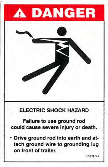
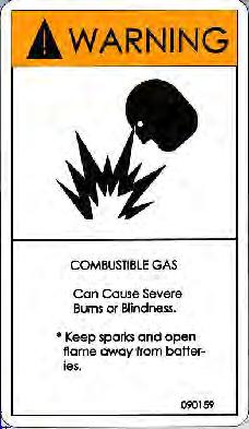

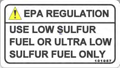
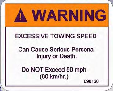


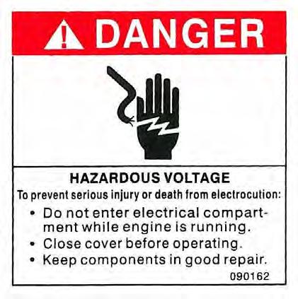
11 SAFETY SAFETY LABELS Refer to these representations of the safety warning decals used on the MAXI-LITE AS3000 light tower to insure correct ordering if replacement becomes necessary. 11


12 TRAILERING, TRANSPORTING AND LIFTING PREPARING THE UNIT FOR DELIVERY OR RENTAL The MAXI-LITE AS3000 light tower should be operated properly and maintained properly for maximum service life. Never deliver or put machine into service with known defects or missing instructions or decals. Always instruct the customer in proper operation and safety procedures as described in this Operator s Manual. Always provide the manual with the equipment for proper and safe operation. CHECK LIST Visually inspect the equipment to ensure that all instructions and decals are in place and legible. Inspect the light tower locking bar latch assembly which locks the light tower in the vertical position for proper operation. Check the hitch assembly and safety chains. Check the outriggers and jacks to make sure they operate properly. Inspect the light assemblies for damage and test for proper operation. Inspect the electrical wiring for signs of damage. Check ground rod cable and the ground lug. Make sure they are clean, undamaged and functional. Inspect tires to insure good condition and proper inflation. Check engine oil, fuel, engine coolant levels and hydraulic fluid levels, if equipped. Check to make sure the Light Tower Operator s Manual, Engine Operator s Manual and the Generator Operator s Manual are with the equipment. Inspect the machine physically for damage and repair if necessary. After completing the pre-operation check list, operate the tower through a complete operation cycle, following the operating instructions in the MAXI-LITE AS3000 Operator s Manual. ALWAYS READ AND UNDERSTAND THE INSTRUCTIONS FIRST. 12


13 TRAILERING, TRANSPORTING AND LIFTING BEFORE TRAILERING OR TRANS- PORTING Before trailering, transporting or lifting, read Safety on page 7. Perform the following before trailering / transporting: Lower the light tower and shut down the tower lights and the engine; See Shutdownprepare for trailering on page 13. Visually inspect the trailer and equipment for damage. Repair or replace any components as needed before trailering. Check the trailer lights for proper operation Inspect the tires to insure good condition and proper inflation. Inspect trailer springs and undercarriage for damage or loose parts. Check the hitch assembly and safety chains. Ensure the outriggers and jacks are properly stowed. Ensure the ground rod and cable are disconnected and properly stowed. SHUTDOWN - Prepare for trailering 1. With the tower lights off, lower the light tower to the full DOWN position; See Raising and lowering the light tower on page Turn the engine off. Refer to your Engine Operator s Manual for stopping procedure. 3. Adjust the light bar and light fixtures for trailering; See Tower Lights-Stowage for trailering on page Secure the light cords into the hook on the rear tower support.(laydown Tower Only) 5. Disconnect the ground rod cable rod the ground lug. Remove the ground rod from the earth and clean and secure the ground rod and cable in the trailer. 6. Close, secure and lock all compartment doors. Clean any spills from inside the trailer bilge area around the outside of the trailer; they may have occurred during operation. Ensure all compartment doors are closed and securely locked. 7. Raise each outrigger stabilizer jack and rotate into trailering position (horizontal with outrigger bar). 8. Retract each outrigger bar and secure in the stowed position with latch pin. 13
14 TRAILERING, TRANSPORTING AND LIFTING VERTICAL TOWER LIGHTS - Stowage for Trailering The light bar and fixtures must be stowed before trailering or transporting. 1. Ensure lights are off and tower is lowered to the full DOWN position; See Raising and Lowering the Light Tower on page Release the light bar park pin by pulling the ring and turning it 90 so that the pin remains in the retracted position. 3. Rotate the light bar into the trailering/ transporting park position (inline with the trailer) and engage the park pin by twisting the park pin ring until the plunger is released and the pin engages and locks into the hole in the light bar. 4. Reposition the light fixtures for trailering/ transporting by pulling them down into the lowest position and face the fixtures toward the center of the trailer. (See Right ) If lights are to be removed for trailering/ transporting, See Tower Lights - Removal for Trailering/ Transporting on page
15 TRAILERING, TRANSPORTING AND LIFTING LAYDOWN TOWER LIGHTS - Stowage for Trailering The light bar and fixtures must be stowed before trailering or transporting. 1. Ensure lights are off and tower is lowered to the full DOWN position: See Raising and Lowering the Light Tower on page Rotate the light bar into the trailering/ transporting park position (inline with the front of the trailer) and tighten the tower lock knob. 3. Lower the tower into the rear tower support and engage tower lock. 4. Reposition the light fixtures for trailering/ transporting by facing the fixtures toward the mast (See right) If lights are to be removed for trailering/ transporting, See Tower Lights -Removal for trailering/ transporting (optional) on page

16 TRAILERING, TRANSPORTING AND LIFTING TOWER LIGHTS - Removal for Trailering/ Transporting (optional) Your light tower may be equipped with lights that can be removed for trailering/ transporting or for theft protection. 1. Ensure lights are off and tower is lowered to the full DOWN position; See Raising and Lowering the light tower on page Disconnect the electrical cord from each light fixture. 3. While supporting the light fixture, remove the nut and washer for each assembly fastening the main light fixture bracket to the light bar. 4. Store each light fixture to avoid any damage during transport TRAILERING / TOWING Before trailering / towing the light tower trailer, read Before Trailering / Transporting on page 13 and read Safety on page 7. Trailer Component Identification Ball Hitch Coupler Park Brake Safety Chains Tongue Jack 16


 ball hitch.")

17 TRAILERING, TRANSPORTING AND LIFTING Towing Vehicle and Hitch Considerations Hitch and Coupler PARK BRAKE The towing vehicle must be able to safely pull the full trailer load. Never pull a trailer load that exceeds the vehicle s towing capacity. The vehicle must have a towing hitch that is capable of safely handling the trailer load and tongue weight of the trailer. Before trailering, always check your vehicle owners manual for maximum towing/ trailering load specifications and maximum gross vehicle weight specifications that include the fully loaded trailer. Connecting the Trailer Hitch Coupler and Lights The trailer is equipped with a trailer coupler for a 50mm (2 inch) ball hitch. TRAILER COUPLER SOCKET LATCH AND RELEASE LEVER VEHICLE HITCH AND BALL The trailer s safety chains prevent the trailer from completely detaching from the vehicle when underway. In the event the trailer separates from the vehicles hitch and ball. 1. Connect the trailer coupler to the tow vehicle s hitch and ball. Make sure the coupler is securely attached to the tow vehicle s hitch. 17


18 TRAILERING, TRANSPORTING AND LIFTING 2. Connect the safety chains to the vehicle s hitch frame and crisscross the chains under the trailer tongue to prevent the tongue from dropping to the road if the trailer separates from the hitch ball. Rig the chains as tight as possible with enough slack to permit free turning. 3. Connect the 7-pin light connector from the trailers harness to the vehicles harness. 4. Ensure there is adequate slack in the harness to prevent binding or disconnection when turning. 5. Before trailering, check all lights for proper operation. 7-pin Trailer Light Harness Connector BOTTOM VIEW OF HITCH AND COUPLER PROPER CHAIN CONNECTION LIFTING THE LIGHT TOWER The approximate fully loaded weight of the light tower and trailer is: Vertical tower - 1,271.4 kg (2,803lbs) Laydown tower - 1,173.9 kg (2,588 lbs) The MAXI-LITE AS3000 light tower is equipped with top forklift pockets and a lifting eye for lifting or hoisting. Trailer Safety Chains 18


19 TRAILERING, TRANSPORTING AND LIFTING LIFTING ATTACHMENT POINTS - Vertical Tower FORKLIFT POCKETS LIFTING EYE 19 LIFTING ATTACHMENT POINTS - Laydown Tower FORKLIFT POCKETS LIFTING EYE TRANSPORTING ON A TRAILER When transporting the light tower trailer on a truck or a trailer, always secure the unit using properly rated tie-down chains or straps connecting the light tower frame using tie-down loops to the towing trailer. The operator of the towing vehicle is responsible for securing the load properly.
20 GENERAL SERVICE INFORMATION EQUIPMENT IDENTIFICATION VERTICAL TOWER LAMP ASSEMBLY LIGHT BAR BATTERY DISCONNECT SWITCH HYDRAULIC LIGHT TOWER STEP PLATE (Hydraulic Only) PARK BRAKE COUPLER FRONT OUTRIGGER LIFTING BAR LEFT FUEL TANK AND CONTROL ACCESS DOOR EMERGENCY STOP BUTTON BALLAST ACCESS COVER PANEL FRONT STABI- LIZER JACK SAFTEY CHAINS TRAILER TONGUE JACK 20
21 GENERAL SERVICE INFORMATION EQUIPMENT IDENTIFICATION LAYDOWN TOWER LAYDOWN LIGHT TOWER BATTERY DISCONNECT SWITCH PARK BRAKE COUPLER LIFTING EYE LAMP ASSEMBLY FRONT OUTRIGGER CORD REEL FORKLIFT POCKETS LEFT FUEL TANK AND CONTROL ACCESS DOOR FRONT STABILIZER JACK SAFETY CHAINS EMERGENCY STOP BUTTON BALLAST ACCESS PANEL TRAILER TONGUE JACK 21

22 MODEL AND SERIAL NUMBERS GENERAL SERVICE INFORMATION Model and serial number information is required for product support and repair parts. The following descriptions show model and serial number locations of the primary components. Trailer All MAXI-LITE AS3000 light tower trailers have a serial number plate attached to the rear panel. TRAILER SERIAL PLATE Generator The generator has a serial number plate attached to the side of the housing. STAMPED SERIAL PLATE Engine The CATERPILLAR engine has a serial number plate attached on the upper right side of the engine block above the fuel injection pump. SERIAL PLATE CAT ENGINE C1.1 SPECIFICATIONS (STANDARD AND OPTIONAL FEATURES) Refer to the Engine Operator s Manual or the Generator Operator s Manual for specific Engine or Generator specifications. MARATHON 22
23 Overall Dimensions GENERAL SERVICE INFORMATION Hydraulic Tower Laydown Tower Height Light Tower Lowered 2.34 m (7 Ft 8 in.) 1.7 m (5 ft. 7in.) Height Light Tower Raised 7.8 m (25 ft 6in.) 9.14 m (30 ft.) Width (outriggers retracted) 1.9 m (74 in.) 1.95 m (76 ft. 3/4 in.) Manual Winch 1.87 m (74 in.) Electric Winch Width (outriggers extended) 3.91 m (12 ft 10 in.) 3.91 m (12 ft. 10 in.) Length w/o Fixtures 3.14 m (10 ft 4 in.) 4.1 m ( 13 ft. 6 in.) Length with Fixtures 3.14 m (10 ft 4 in.) 4.5 m ( 14 ft. 9 in.) Dry Weight (4 lights) 1,036 kg (2,503 lbs.) 1,038 kg (2,288 lbs.) 23
24 Trailer Hitch Coupler Fixed height 50 mm (2 in.) ball Max. Road Speed (paved road) 60 mph (97 km/h) Max. Off - road Speed 20 mph (32 km/h) Number of Axles 1 Axle Rating 5000 lbs. (907.1 kg) Tire Size & Rating ST 225/75 D15 Max Tire Pressure 448 kpa (65 PSI) Door Locks Standard Trailer Lights: Stop, Turn, Running Trailer llight Connector 7 - Pin Plug Lifting Eye Standard Tie - Down Rings Standard Side Forklift Pockets Standard Top Forklift Pockets Standard Number of Stablizers 4 Number of Outrigger Stabilizers 2 Tongue Jack Standard Ground Rod GENERAL SERVICE INFORMATION Standard Light Tower Vertical Sections 6 Hydraulic Cylinder Standard Vertical Max Wind Load Optional 85.3 km/h (57 mph) Light Bar Rotation 360 Cord Reel Optional Light Tower Laydown Sections 3 Hydraulic Cylinder Rear Tower Support Max Wind Load N/A Standard 85.3 km/h (53 mph) Light Fixture Rotation 360 Cord Reel Standard Manual Winch Standard Electric Winch Option 24
25 Tower Lights GENERAL SERVICE INFORMATION SHO - HD 1250W Metal Halide (lumen rating: 150,000) Standard SHO - HD 1000W Metal Halide (lumen rating: 110,000) Optional SHO - HD 1000W and 1250W Metal Halide SHO - HD 1000W and 1205W Metal Halide Four Fixtures Light Fixture Weight Indivdual Light Switches 1000W Light Switch (2 per 4 lights) 1000W Light Switch (4 per 4 lights) 1250W Light Switch (2 per light) Individual Ballast (1 ballast per light) Generator 7.5 kw Standard 8 kw Optional Warm - up time: 2-4 minutes Re - start time: 10 to 15 minutes Standard (sealed for all weather use) 15 lbs (6.75 kg) Standard Optional Standard Standard 25
26 Bore Stroke Displacement GENERAL SERVICE INFORMATION 77mm (3.03 in.) 81mm (3.19 in.) 1100cc (69 cu. In.) 1800 rpm 11.9 kw (14.3 bhp) Power Output 3% per 304.8m (1000 ft.) above 109.7m (360 ft.) Derating 1% per 10 above 25 C (77 F) Note: Horse power ratings are established in accordance with Society of Automotive Engineers Small Engine Test Code J1349 GROSS Fuel System Cassette type fuel injected diesel Starting System 12VDC Negative Ground Electrical System 12VDC Negative Ground Battery Type Group 24 Battery Rating 550 CCA Number of Batteries 1 Compression Ratio 22:01 Weight 87 kg (191 lbs.) Oil Capacity 3.7 L (3.9 qts.) Lubrication Forced lubrication by Pump Oil Filteration Cartridge Type Cooling System Pressurized radiator forced circulation with water pump Low Oil Pressure Engine Shutdown High Engine Standard Tempurature Shutdown Glow Plug Cold Start Assist Fuel Use a clean No. 2 Diesel fuel oil (SAE J313 JUN87) according to ASTM D975 Do not use alternative fuel, because its quality is unknown or it may be inferior in quality, kerosene, which is very low in cetane rating, adversely affects the engine. Refer to the Engine Operator's Manual for more dtailed fuel requirements. Engine Oil Use a high quality engine oil of API (American Petroleum Institute) service class CC/CD/CE. Refer to the Engines Operator's Manual for a more detailed engine oil requirements. Fuel Tank 189 L (50 gal.) Cooling System See Engine Operator's Manual Engine Oil See Engine Operator's Manual 26
27 GENERAL SERVICE INFORMATION OPTIONAL ACCESSORY EQUIPMENT Saf -T-Visor Electric Winch Tower Hydraulic Tower LSC100 Light Sequence Commander Heavy Duty Battery (700 CCA) Battery Heating Pad Engine Block Heater Sound Attenuation package Four or Six Metal Halide or High Pressure Sodium Lamps (5,000, 6,000 or 7,000 Watts Total) 7-Blade RV Taillight Connector 189 L (50 gal.) Bulldog Hitch (ball/pintle) Quick - Disconnect Lamp Fixtures Battery Disconnect switch Emergency Stop Switch 27


.")
28 PRE-OPERATION SETUP Work site safety considerations Overhead Obstructions Position the light tower trailer where there are no overhead obstructions. Ensure that there is sufficient clearance from structures, trees and wires before raising the light tower. Ground Surface Check the ground conditions where you intend to set up the light tower trailer. The ground must offer firm, stable footing for the outriggers and jacks. The area must be flat and level. Wind The light tower will remain operational in sustained winds up to 92 km/h (57 mph) when properly positioned on firm level ground, with the outriggers and jacks properly positioned, and the light tower fully raised. OPERATION Pre - Operation Check list Always perform the following checks before traveling to the work site and before operation. Repair or replace any components as required before operation. Visually inspect the equipment to ensure that all instructions and decals are in place and legible. Inspect the light tower locking bar latch assembly, which locks the light tower in the vertical position for proper operation. (Laydown Tower only). Check the hitch assembly and safety chains. Check the outriggers and jacks to make sure they operate properly. Inspect the light assemblies for damage and test for proper operation. Inspect the electrical wiring for signs of damage. Check the ground rod cable and ground lug. Make sure they are clean, undamaged and functional. Inspect the tires to ensure good condition and proper inflation. 28

29 OPERATION Check engine oil, fuel, engine coolant levels and hydraulic fluid levels, if equipped. PARK BRAKE Check to make sure the Light Tower Operator s Manual, Engine Operator s Manual and Generator Operator s Manual are with the equipment. Physically inspect the machine for damage and repair if necessary. After completing the pre-operation check list, operate the light tower through a complete operation cycle. Leveling and Stabilizing the Trailer 1. Position the MAXI-LITE AS3000 on an adequate site: See Work Site Safety Considerations on page Block each wheel on each side with a suitable wheel chock. 3. Set park brake. 29 Wheel Chock Blocks

30 3. Extend the front outrigger stabilizers out and lock in place. OUTRIGGER LOCK PIN OPERATION JACK HANDLE JACK LOCK PIN 4. Rotate the rear stabilizer jack perpendicular with the ground and lock in place. 5. Adjust each front stabilizer jack and the tongue jack to achieve proper leveling. Turning the handles clockwise will raise the jacks and counterclockwise will lower the jacks. JACK HANDLE Installing the Ground Rod The ground rod is a safety devise that may reduce the chance of personal injury from stray electrical current. Allmand recommends using the ground rod. However, it is the user s responsibility to determine the requirements and/ or applicability of local, state or national electrical code which governs the use of the ground rod. Drive the ground rod fully into the ground using a hammer. Attach the supplied cable to the rod and then attach the cable to the ground lug on the unit. Make sure the cable connections are tightened. GROUND ROD STORAGE LOCATION GROUND ROD CONNECTION GROUND ROD GROUND ROD CABLE EARTH/GROUND 30


31 ENGINE OPERATION Before starting the engine or operating the light tower, review Safety on page 7. The Allmand MAXI-LITE AS3000 light tower is powered by a diesel engine and generator unit. Pre Start Checks 1. Check the engine oil and add oil if required. Fill the engine with the proper grade of lubricating oil: refer to Engine Operator s Manual for oil specifications. 2. Check and add diesel fuel as required. 3. Ensure that the air cleaner is firmly attached and air cleaner seals and hose clamps are properly sealed. Air cleaner element should be checked and replaced if necessary. Engine Control Panel The engine control panel consists of the engine start/stop key or button, hour meter. CAT C1.1 control panel HOUR METER VOLT METER OPERATION KEY SWICH Starting the Engine The Starting procedure is different depending on the engine model used. Refer to your Engine Operator s Manual for the starting procedure. Cold - Weather Starting The cold-weather Staring procedure is different depending on the engine model used. Refer to your Engine Operator s Manual for the cold-starting procedure. If Engine has Run Out of Fuel 1. Refill the fuel tank. 2. Refer to your Engine Operator s Manual for the starting procedure. If starter is engaged while the flywheel is rotating, the starter pinion and flywheel ring gear may clash, resulting in damage to the starter or flywheel ring gear. Stopping the Engine The engine stopping procedure may differ depending on the engine model. Refer to your Engine Operator s Manual for engine stopping procedures. 31
32 Emergency Stop Switch The MAXI-LITE AS3000 light tower trailer is equipped with an emergency Stop switch. Which will cut the power to the engine in case of on emergency. The switch must be reset in order to restart the engine. Battery Disconnect The light tower trailer is supplied with a lockable battery shut off switch. The switch disconnects the power from the battery to all electrical components. The switch must be in the ON position to start the engine. Automatic Engine shutdown System The engine is equipped with an automatic engine shutdown system to prevent excessive engine damage in the event of a low oil or overheat condition. For additional information, refer to your Engine Operator s Manual. Low Oil Pressure Shutoff Should a low oil pressure condition occur, the oil pressure sending unit breaks the circuit between the circuit between the battery and the fuel solenoid, allowing the spring load to immediately move the fuel control to the shutoff position. High Coolant Temperature Shutoff Should a high coolant temperature condition occur, the temperature sending unit breaks the circuit between the battery and the fuel solenoid, allowing the spring load to immediately move the fuel control to the shutoff position. TOWER AND LIGHT OPERATION VERTICAL Before operating the tower lights, review Safety on page 7. OPERATION 32 The vertical tower is raised and lowered by a hydraulic pump actuating a six section telescoping mast. TOWER AND LIGHT OPERATION LAYDOWN Before operating the tower lights, review Safety on page 7. The laydown light tower is raised and lowered by a manual winch actuating a three section telescoping mast.


33 Light Bar and Light Fixture Adjustment-Vertical Lights Work Site Adjustment The light bar and light fixtures must be adjusted to the desired work angle before raising the light tower. With the light tower fully lowered and the lights off, the light bar assembly and light fixtures can be manually rotated into the desired position. To adjust the light bar, release the light bar park pin by pulling the ring and turning it 90 so that the pin remains in the retracted position. PARK PIN With the light bar park pin released, the light bar is designed to be manually rotated with enough resistance so that the bar will stay in the desired position once the operator has directed the lights on the work zone. OPERATION 33 If the light bar rotates too easily or does not stay in position, remove the cap plug from the center of the light bar cover and tighten the nut to achieve the desired resistance and replace the cap plug. To adjust each light fixture, manually swivel each light fixture at its base into the desired working position. GRASP THE LIGHT HERE TO ADJUST Cap Plug The light bar and light fixtures must be stowed properly for trailering or transporting. See Tower Lights-Stowage for trailering-vertical on page 14.
34 Light Bar and Light Fixture Adjustment-Laydown Lights Work Site Adjustment The light bar and light fixtures must be adjusted to the desired work angle before raising the light tower. With The Light tower fully lowered and the lights off, the light fixtures can be manually rotated into the desired working position. To adjust each light fixture, manually swivel each light fixture at its base into the desired position. GRASP THE LIGHT HERE TO ADJUST OPERATION The light bar and light fixtures must be stowed properly for trailering or transporting. See Tower Lights Stowage for trailering-laydown on page 15. Raising and Lowering the Vertical Tower Light Tower The Hydraulically actuated light tower uses 12VDC Battery power to operate. The light tower may be raised and lowered as needed without the engine running. SIX SECTION LIGHT TOWER Raising Before raising the light tower, visually inspect the equipment for worn or damaged parts and replace or repair as necessary. 34


35 1. Before raising the light tower, adjust the tower lights to the desired work position; see Light Bar and Light Fixture Adjustment- Vertical on page Turn the lights off; see Light Control Panel on page Press the light tower lift switch up to raise the light tower to the desired height. Lowering LIGHT TOWER HYDRAULIC LIFT SWITCH 1. Turn the lights off; see Light Control Panel on page Press the tower light hydraulic lift switch down to lower the light tower to the desired height or to the full DOWN position. 3. When tower reaches the bottom, run switch for three additional seconds to ensure that the tower is at its lowest possible position. 4. Stop engine. OPERATION Raising and Lowering the Manual Winch Light Tower Laydown Manual Winch Light Tower The manual winch tower can be raised and extended by operating two hand crank winches. One winch, mounted with the handle extending through the left side of the trailer frame, raises and lowers the mast from horizontal towing position to the vertical position and back. The second winch mounted on the tower extends and retracts the telescoping sections. Before raising the light tower, visually inspect the equipment for worn or damaged parts and replace or repair as necessary. REAR SUPPORT RELEASE PIN MANUAL WINCH TOWER LOWER HAND WINCH HANDLE UPPER HAND WINCH HANDLE HANDLES MAST ROTATION LOCKING KNOB MAST LOCKING KNOB 35
36 Raising 1. Before raising the light tower, adjust the tower lights to desired position; see Light Bar and Light Fixture Adjustment-Laydown on page Turn the lights off; see Light Control Panel on page Release the pin that secures the mast to the rear mast support. 4. Operate the hand crank on the left side of the trailer to raise the mast from horizontal to vertical. 5. Engage automatic mast locking pin. 6. Operate the hand crank winch on the tower clockwise to raise the lights vertically. 7. To rotate lights to desired position, turn mast rotation locking knob counterclockwise and turn the tower with handles provided. Lowering 1. Turn lights off; see Light Control Panel on page Loosen mast rotation locking knob and rotate tower until the handles are parallel with the front of the trailer and retighten mast rotation locking knob. 3. Operate hand crank winch on tower counterclockwise to lower the lights to the lowest vertical position. 4. Operate lower hand crank winch on the left side of the trailer clockwise to take up any slack in the cable. 5. Disengage automatic mast locking pin. 6. Operate the lower hand crank on the left side of the trailer counterclockwise to lower the mast into the horizontal towing position. OPERATION 7. Secure light cords into hook on the rear mast support. 8. Secure rear mast support release pin. Locking the mast to the rear mast support for towing. Raising and Lowering the Electric Winch Light Tower Laydown Electric Winch Light Tower The electric winch tower can be raised and extended by operating a single electric switch mounted on the light switch control panel. ELECTRIC WINCH TOWER MAST LOCKING KNOB MAST ROTATION LOCKING KNOB HANDLES REAR SUPPORT RELEASE PIN SAFETY LATCH HANDLE AND PIN Before raising the light tower, visually inspect the equipment for worn or damaged parts and replace as necessary. 36

37 OPERATION Raising Lowering 1. Before raising the light tower, adjust the tower lights to the desired work position; see Light Bar and Light Fixture Adjustment- Laydown on page Start engine. Refer to your Engine Operator s Manual for starting procedure. 3. Switch the 120V circuit breaker switch to the ON position. 4. Release the pin that secures the mast to the rear tower support. 5. Push the toggle switch to the UP position to raise the tower from horizontal to vertical. 6. Turn lower black knob counterclockwise and engage latch in strike plate. Retighten knob. 7. Remove Safety Latch pin 8. Release the latch by squeezing the auto bar handle and push the toggle switch to the UP position to raise the lights. AUTO BAR 1. If required, start engine. Refer to your Engine Operator s Manual for starting procedure. 2. Turn the lights off; see Light Control Panel on page Loosen upper black knob. Rotate tower by handles until handles are parallel with the front of the trailer. Retighten knob. 4. Push toggle switch to the DOWN position to lower the light to the lowest vertical position until the safety latch clicks. 5. Push toggle switch to the UP position to lessen slack in the cable. 6. Turn lower black knob counterclockwise and lift to release the latch pin from the strike plate. Retighten the lower knob with the latch disengaged from the strike plate. 7. Push toggle switch to the DOWN position to lower the mast into a horizontal towing position. 8. Secure cord onto hook on the rear tower support. 9. Secure rear support release pin, locking mast to rear tower support for towing. AUXILIARY HANDLE - Electric winch NOTE: An emergency crank handle is provided for use in the event of a power failure. 1. Remove electrical power from the winch. 9. To rotate the lights. Turn upper black knob counterclockwise to loosen. Use handles and turn to desired position Insert the handle so that it completely engages with the drive shaft. The handle can be cranked in either direction with the clutch in the engaged position. 3. Always remove the emergency handle after use to avoid damage.


38 OPERATION ELECTRIC WINCH EMERGENCY CRANK HANDLE Light Control Panel The tower light control panel consist of the breaker switches. The four light fixtures are controlled and protected by four breaker switches located on the light control panel. Lights On Turn the light breaker switches to the ON position. One to four lights may be used Lights Off Turn all light breaker switches to the OFF position. SHUTDOWN PROCEDURE Shutdown When shutting down the light tower perform the following procedures. 1. With the lights off, lower the light tower to the full DOWN position; see Raising and Lowering the Light Tower on page LIGHT BREAKER SWITCHES 2. Turn the engine off. Refer to your Engine Operator s Manual for stopping procedure. 38

39 Before performing any maintenance procedures, read Safety on page 7. Scheduled maintenance prevents unexpected downtime, and helps extend the life of the light tower. Proper maintenance and care of your light tower and trailer is a must for safe and reliable operation. Use the following maintenance and care guidelines in addition to those scheduled by your shop s preventative maintenance schedule. Where equipment is operated under severe conditions (very dusty, extreme heat or cold, etc.), affected items should be serviced more frequently. ENGINE Refer to the Engine Operator s Manual for all engine scheduled maintenance procedures. Changing and Adding Engine Oil Use a high-quality engine oil of API (American Petroleum Institute) service class CC/CD/CE. Refer to the Engine Operator s Manual for detailed engine oil specifications and service procedures. All models can be equipped with the remote oil drain. Engine Filters Refer to the Engine Operator s Manual for air, oil and fuel filter service procedures. MAINTENANCE ELECTRICAL SYSTEM Refer to the Generator Operator s Manual for all general scheduled maintenance procedures. Ballast Panel The ballast panel is located on the left, front side of the light tower trailer. The ballast panel can be accessed by removing the left front panel. The ballast panel contains four tower light lamp ballast and four capacitors. For additional wiring information, see schematics or contact Allmand Bros. or your Allmand dealer. 39

40 CAPACITORS LAMP BALLAST HYDRAULIC PUMP Hydraulic Oil Specification MAINTENANCE Adding Hydraulic Oil Fill the reservoir with an iso viscosity grade 10 or 15 hydraulic fluid or any clean hydraulic fluid having a viscosity index that is suitable for the climate conditions in which the unit will be operated. Standard units are supplied with automatic transmission fluid (ATF), and arctic units are supplied with iso viscosity 10 or 15 hydraulic fluid. Priming the Hydraulic Pump The ports are marked on the hydraulic power unit casting: UP and DN. When facing the power unit with the motor up, plug the right hand, or DN port. Jog the motor until oil flows from the left hand or UP port. The pump is now primed. Connect the hose or tubing to the UP port and tighten. Connect the other hose end to the blind end of a fully retracted hydraulic cylinder. With the hose fitting loose, operate the power unit until oil (and no air) bleeds from the fitting. Tighten the fitting. Refill the reservoir. 40
41 MAINTENANCE LIGHT TOWER AND LAMPS Changing Lamps 4. Remove the silicone gasket and lens. 5. Remove the support clip screws and support clip. 1. Turn off the lights and shut off the engine. Allow the bulbs and fixtures to cool. 2. Lower the light tower to the full DOWN position. 3. Loosen the lens channel screws to allow the removal of the lens channel. SUPPORT CLIP SCREWS LAMP LENS CHANNEL SCREWS And NUTS (2 each) REFLECTOR SUPPORT CLIP LENS SILICONE GASKET LENS CHANNEL 6. Carefully remove the old lamp and install the correct replacement lamp. 7. Clean reflector and lens. 8. Install support clip and screws. 9. Install the silicone gasket and lens; replace if damaged or as needed. 10. Install lens channel and screws. 11. Test the new lamp to ensure proper operation. TRAILER Proper maintenance and care of your trailer is a must for safe and reliable operation. Follow these maintenance and care guidelines in addition to those scheduled by your shop equipment maintenance schedule. Frame 1. Check the coupler for proper operation, and for corrosion or damage replace as needed. 2. Inspect the lifting bar for corrosion or damage and replace as needed. 3. Inspect the axle, springs and undercarriage for wear and damage and replace as needed. 4. Inspect the outrigger bars, front and rear stabilizer jacks and locking mechanisms for proper operation and wear and damage and replace as needed/ 5. Inspect the safety chains for wear, corrosion or damage and replace as needed. 41
42 Grease Points Use N.G.L.I. consistency #2 high-temperature anti- friction bearing lubricating grease for all trailer mechanical pivot points. Trailer Wheels and Tires 1. Check the tires for any cracks, cuts or damage. Repair or replace the damaged tires before towing. 2. Check the air pressure of the trailer tires when cold. The correct air pressure for the tire is specified on the tire. Never over or under inflate tires. 3. Check the wheel rims for any cracks or damage. 4. Make sure all the lug nuts are in place. Never tow the trailer with missing or improperly tightened lug nuts. 5. Check that the lug nuts are tightened properly. The correct torque for the lug nuts is 90 lb-ft (122N-m). 6. When torquing the lug nuts, always use a crisscross pattern. MAINTENANCE Wheel Bearings Wheel bearings require periodic maintenance. More frequent service may be required under extremely dust or damp operating conditions. The best protection against failure is to keep the wheel bearings clean and fully lubricated. When replacing or repacking wheel bearings, always: GREASE SEAL COTTER PIN DUST COVER WHEEL HUB Use a high quality wheel bearing grease. Avoid mixing grease types. INNER BEARING WASHER CASTLE NUT Clean all components thoroughly of all grease and inspect for damage and wear. Replace as needed. Always use a new grease seal and cotter pin. Keep all components clean during assembly. OUTER BEARING Replace any component that is operationally questionable. Pack grease into the bearing before installing it. 42
43 Keep the lights in proper working order. Always replace bearings and races as a set. Never mix bearings and races. Bearing part numbers are sometimes found on the bearing races; always use the correct bearing set. Do not over or under tighten the bearing nut. Wheel bearings should only be tightened by hand (spin the wheel while tightening). Back off the nut to insert the cotter pin. The wheel should spin freely but without play. Pack some grease in the inner hub area and dust cap and ensure the dust cap fits tightly. Trailer Lighting Check that all lights operate properly. Check the trailer lights and harness for damage or wear and replace as needed. Ensure the harness is secured into the trailer and does not hang down onto the ground. Check the taillight housing assemblies for leaks. Use silicone or rubber sealant to seal the lens or harness or replace the housing assembly. Dielectric grease will help protect the sockets and prevent their corrosion. When replacing bulbs, ensure the proper bulb is used and use a small amount of Dielectric grease in the sockets to prevent corrosion. MAINTENANCE For trailer light wiring schematic information, See Tail lamp wiring schematic on page 50. LONG TERM STORAGE Proper maintenance is required when the light tower and trailer will be stored or removed from operation for long periods of time. Refer to the Engine Operator s Manual and the Generator Operator s Manual for all engine and generator long term storage procedures. 1. Lower the light tower to the full DOWN position. 2. Make any repairs necessary to ensure the equipment is fully functional upon returning the unit back into commission. 3. Clean and wash the frame and body panels. Apply an anticorrosion coating to all Surfaces where applicable. 4. Clean any oil or liquid spills inside the engine compartment. 5. Clean all electrical wiring and components by hand using a non-corrosive cleaner. 6. Clean the light tower and light fixture assemblies. 7. Disconnect and remove battery. 8. Use suitable cover to protect the light tower and trailer. 9. Properly support the trailer axle on jack stands or other suitable supports to allow the tires to remain off the ground during storage. 43
44 CLEANING Keeping the light tower clean is important to ensure proper operation. Dirt and dust buildup acts as an insulator and may cause the engine, generator and light assemblies to operate at excessively high temperatures. Use the following guidelines: Use caution when using compressed air or water/steam pressure washers. Do not pressure clean electrical components as this may damage electrical equipment. Clean the light tower and remove all dust, dirt or other foreign material. Inspect and clean the cooling air intake and exhaust louvers of the enclosure. Make sure they are clean. Remove dirt or any buildup that may restrict the cooling air flow. Clean the light tower and its components with a damp cloth or sponge. Inspect and clean all engine linkages so they operate properly. Cleaning and Draining the Trailer Bilge The Allmand MAXI-LITE AS3000 light tower trailers have a fuel containment tray option, designed to catch fuel, oil or coolant spills. Should a spill occur, position a suitable container beneath the unit and remove the containment tray drain plug. After the fluid has been drained, reinstall the drain plug and dispose of the fluid properly in accordance with EPA or other governmental guidelines. MAINTENANCE Before performing any troubleshooting procedures, read Safety on page 7. For engine and generator troubleshooting, see the Engine Operator s Manual and The Generator Operator s Manual or contact Allmand Bros. Service Department or your Allmand dealer. Always follow the electrical component manufacture specifications for voltage and test procedures. 44
45 TROUBLESHOOTING CHART TROUBLESHOOTING PROBLEM POSSIBLE CAUSE 1. The lamp or lamps are burned out or broken or not screwed in securely. 2. Low electrical system voltage. Check volts and engine speed. 3. Too much power is being drawn from the auxillary outlets. 4. A circuit breaker or breakers are defective. NO LIGHT 5. A capacitor or transformer has failed. (ONE OR MORE 6. Plug and socket at light bar not securely pushed together and locked. LIGHTS) 7. A loose connection in the back of the lamp socket in the lamp holder. 8. If the lamps have been on before. Lamps are not allowed time to cool after last being lit. You must allow 15 minutes between the time the lights are shut off and the time they are restarted. 9. A wrong style replacement lamp (requiring a different ballast) has been installed. 10. Corrosion has occurred on the lamp bases. 45
46 MAINTENANCE RECORD DATE SERVICE DESCRIPTION SERVICED BY 46
47 SCHEMATICS 47
48 SCHEMATICS 48
49 SCHEMATICS 49
50 SCHEMATICS 50
51 SCHEMATICS 51

52 WARRANTY 52

53 WARRANTY 53
 YEARS AFTER DELIVERY TO THE ORIGINAL PURCHASER.")
54 LIGHTING SYSTEMS LIMITED WARRANTY ADDENDUM Allmand Bros. Inc. PO Box West 4 th Ave Holdrege, NE / Fax / THIS IS AN ADDENDUM TO THE BASIC ALLMAND LIMITED WARRANTY OF TWO (2) YEARS AFTER DELIVERY TO THE ORIGINAL PURCHASER. The following manufacturers limited warranty policy warrants their components to be free from defects in material and workmanship from date of manufacture as follows (see specific manufacturer s warranty for details): CATERPILLAR TWO (2) YEAR LIMITED 2000 HOURS KUBOTA THREE (3) YEAR LIMITED 3000 HOURS LOMBARDINI/KOHLER THREE (3) YEAR LIMITED 3000 HOURS ISUZU 3CD TWO (2) YEAR LIMITED 2000 HOURS ISUZU 4LE FIVE (5) YEAR LIMITED 5000 HOURS ADVANCE BALLAST TWO (2) YEAR LIMITED -- MARATHON ONE (1) YEAR LIMITED -- MECC ALTE ONE (1) YEAR LIMITED -- STAMFORD ONE (1) YEAR LIMITED -- ATHLON ONE (1) YEAR LIMITED -- LIGHT TOWER ASSEMBLY TEN (10) YEARS FAILURE TO OPERATE DUE TO CORROSION No representative, dealer, or distributor of the company is authorized to make any changes or exceptions to this warranty unless expressly authorized in writing from the manufacturer. All warranty claims must be filed within thirty (30) days of failure. Please call the Allmand Service and Warranty Department for specific manufacturer s warranty terms and schedules. All warranties are subject to change without notice. Limited Warranty LIGHTING SYSTEMS Addendum 11/12
NIGHT LITE PRO II OPERATOR S MANUAL
 REVISED AUGUST 2011 NIGHT LITE PRO II OPERATOR S MANUAL ALLMAND BROTHERS INC. P.O. BOX 888 HOLDREGE, NE 68949 PHONE: (308) 995-4495, 1-800- 562-1373 ALLMAND FAX: (308) 995 5887 ALLMAND PARTS DEPT. FAX
MAXI LITE ML FCS SERIES OPERATOR S MANUAL
 MAXI LITE ML FCS SERIES OPERATOR S MANUAL ALLMAND BROTHERS INC. P.O. BOX 888 HOLDREGE, NE 68949 PHONE: (308) 995-4495, 1-800- 562-1373 ALLMAND FAX: (308) 995 5887 ALLMAND PARTS DEPT. FAX : (308) 995 4883
MAXI-LITE V-SERIES ML 7.5/ML 8 OPERATOR S MANUAL ALLMAND BROS. INC P.O. BOX 888 HOLDREGE, NE 68949
 MAXI-LITE V-SERIES ML 7.5/ML 8 OPERATOR S MANUAL ALLMAND BROS. INC P.O. BOX 888 HOLDREGE, NE 68949 PHONE: 308/995-4495, 1-800/562-1373 ALLMAND FAX: 308/995-5887 ALLMAND PARTS FAX: 308/995-4883 MAXI-LITE
MAXI-LITE HYDRAULIC TOWER 683, 695, 883, 895, and 895XL OPERATOR S MANUAL ALLMAND BROS. INC P.O. BOX 888 HOLDREGE, NE 68949
 MAXI-LITE HYDRAULIC TOWER 683, 695, 883, 895, and 895XL OPERATOR S MANUAL ALLMAND BROS. INC P.O. BOX 888 HOLDREGE, NE 68949 PHONE: 308/995-4495, 1-800/562-1373 ALLMAND FAX: 308/995-5887 ALLMAND PARTS FAX:
Portable Lighting Equipment Operating Instructions Table of Contents
 Portable Lighting Equipment Operating Instructions Table of Generac Magnum Ingersoll Rand TEREX AMIDA TEREX GENIE Model: MLT3060 Model: LIGHTSOURCE Model: Amida AL4000 series Model: TML4000N Generac Magnum
6330 AND 8330 OPERATOR S MANUAL ALLMAND BROS. INC P.O. BOX 888 HOLDREGE, NE 68949
 NIGHT-LITE 6330 AND 8330 OPERATOR S MANUAL ALLMAND BROS. INC P.O. BOX 888 HOLDREGE, NE 68949 PHONE: 308/995-4495, 1-800/562-1373 ALLMAND FAX: 308/995-5887 ALLMAND PARTS FAX: 308/995-4883 NIGHT- LITE SERIES
NIGHT-LITE PRO V SERIES VERTICAL TOWER OPERATOR S MANUAL ALLMAND BROS. INC P.O. BOX 888 HOLDREGE, NE 68949
 NIGHT-LITE NIGHT-LITE PRO V SERIES VERTICAL TOWER OPERATOR S MANUAL ALLMAND BROS. INC P.O. BOX 888 HOLDREGE, NE 68949 PHONE: 308/995-4495, -800/56-373 ALLMAND FAX: 308/995-5887 ALLMAND PARTS FAX: 308/995-4883
en 002. Light Tower LTC 4 REPAIR MANUAL
 0163171en 002 1208 Light Tower LTC 4 REPAIR MANUAL 0 1 6 3 1 7 1 E N LTC Repair This manual covers the following machines: Item No. Revisions Covered 0009375 105 and higher 0620017 103 and higher 0620018
en Light Tower LTC 4 REPAIR MANUAL
 0160487en 004 1208 Light Tower LTC 4 REPAIR MANUAL 0 1 6 0 4 8 7 E N LTC Repair This manual covers the following machines: Item No. Revisions 0009375 104 and lower 0009376 102 and lower 0620017 102 and
SPORT/UTILITY BLADE ASSEMBLY INSTRUCTIONS
 WESTERN PRODUCTS, P.O. BOX 245038, MILWAUKEE, WI 53224-9538 FORM NO. 13629 September 1, 1999 SPORT/UTILITY BLADE ASSEMBLY INSTRUCTIONS Sport/Utility Blade No. 61300 A, Q & L Box No. 61930 Hydraulics Box
MODEL HD99 HYDRAULIC ONE MAN TOWABLE EARTHDRILL
 DO NOT THROW AWAY IMPORTANT MANUAL MODEL HD99 HYDRAULIC ONE MAN TOWABLE EARTHDRILL Operators Manual GROUND HOG, INC. P.O.BOX 290 San Bernardino, CA. 92402 Phone (909) 478-5700 Fax (909) 478-5710 E-mail:
Log Splitter. Owner/Operator Manual. Models HCWP1-26
 Log Splitter Owner/Operator Manual Models HCWP1-26 SAFETY..........................2 SAFETY WARNING SYMBOL.........3 SAFETY RULES.................. 4-5 SPECIFICATIONS................. 6 CONTROLS AND FEATURES.......
2500 LB ELECTRIC A-FRAME JACK OWNER S MANUAL
 2500 LB ELECTRIC A-FRAME JACK OWNER S MANUAL SPECIFICATIONS: Models Applicable: 2500 lb Electric A-Frame Jack Maximum Lift Capacity: 2500 lbs (continuous use) Retracted Height: 31 3 /8 Vertical Travel:
STANDARD STEEL PLOW BLADE ASSEMBLY INSTRUCTIONS
 WESTERN PRODUCTS, P.O. BOX 245038, MILWAUKEE, WI 53224-9538 FORM NO. 13590 September 1, 1999 STANDARD STEEL PLOW BLADE Blade No. 60120 or 60125, or 60018 A, Q, & L Box No. 61720 Hydraulics Box No. 56365
Models 8100PP & 86110LP. Installation Instructions CAUTION. Read this document before installing the snowplow. CAUTION
 September 15, 2010 Lit. No. 48645, Rev. 02 POWER PLOW Snowplows Models 8100PP & 86110LP Installation Instructions Read this document before installing the snowplow. See your BLIZZARD outlet/web site for
RedGum GP160 Splitter. Owner s Manual
 RedGum GP160 Splitter Owner s Manual Product Description & Intended Purpose: This Log Splitter / Wood Splitter is an outdoor product that splits wood logs for use as fuel in a fireplace or a woodstove.
before serial number 2214
 before serial number 2214 Contents Page Safety Rules... 3 Pre-operational & Safety Inspection... 4 Operating Instructions... 6 Transport... 12 Maintenance & Routine Service... 12 Specifications... 14 SAFETY
Brake System H TX, H2.0TXS [B475]; H TX [B466] Safety Precautions Maintenance and Repair
![Brake System H TX, H2.0TXS [B475]; H TX [B466] Safety Precautions Maintenance and Repair](/thumbs/86/93834005.jpg "Brake System H TX, H2.0TXS [B475]; H TX [B466] Safety Precautions Maintenance and Repair") HMM180001 Brake System H1.5-1.8TX, H2.0TXS [B475]; H2.5-3.5TX [B466] Safety Precautions Maintenance and Repair When lifting parts or assemblies, make sure all slings, chains, or cables are correctly fastened,
HMM180001 Brake System H1.5-1.8TX, H2.0TXS [B475]; H2.5-3.5TX [B466] Safety Precautions Maintenance and Repair When lifting parts or assemblies, make sure all slings, chains, or cables are correctly fastened,
KMH. Series MARINE GEAR OPERATION MANUAL KMH70A P/N: 0AKMH-G00300
 KMH Series OPERATION MANUAL KMH70A P/N: 0AKMH-G00300 MARINE GEAR Disclaimers: All information, illustrations and specifications in this manual are based on the latest information available at the time
KWSL2000RM ! CAUTION!! READ AND UNDERSTAND THIS MANUAL BEFORE INSTALLATION AND OPERATION OF THIS PRODUCT. DO NOT RETURN THIS PRODUCT TO SELLER.
 Assembly & Operating Instructions KWSL2000RM 2000 Lb. 12VDC Electric Winch! CAUTION!! READ AND UNDERSTAND THIS MANUAL BEFORE INSTALLATION AND OPERATION OF THIS PRODUCT. DO NOT RETURN THIS PRODUCT TO SELLER.
Table of Contents. Safety symbols... 3 Assembly 6. Operation Maintenance Troubleshooting 11. Storage. 12. Notes. 13
 Table of Contents Safety symbols... 3 Assembly 6 Operation... 8 Maintenance... 10 Troubleshooting 11 Storage. 12 Notes. 13 2 Safety Information Attention; this machine can be dangerous! All operators should
LUBRICATION AND MAINTENANCE
 DN LUBRICATION AND MAINTENANCE 0-1 LUBRICATION AND MAINTENANCE TABLE OF CONTENTS LUBRICANTS... 1 MAINTENANCE SCHEDULES... 3 JUMP STARTING, TOWING AND HOISTING... 8 LUBRICANTS TABLE OF CONTENTS SERVICE
Model: SPTOGT01 TRACTOR PTO GENERATOR
 www.scintex.com.au sales@scintex.com.au Model: SPTOGT01 TRACTOR PTO GENERATOR SET UP, OPERATING, AND SERVICING INSTRUCTIONS Read this material before using this product. Failure to do so can result in
Wheel Horse. 44 Snowthrower. for 5xi Lawn and Garden Tractors. Model No & Up. Operator s Manual
 FORM NO. 8 Rev A Wheel Horse Snowthrower for 5xi Lawn and Garden Tractors Model No. 7966 890050 & Up Operator s Manual IMPORTANT: Read this manual, and your tractor manual, carefully. They contain information
NOTES FOR SAFETY OPERATOR-ONLY.
 NOTES FOR SAFETY Both the parents and their child must fully understand everything in this manual before riding. This vehicle is for OPERATOR-ONLY. This vehicle is only designed for operation on level,
Light condition and operation Windshield glass condition Wiper blade condition Paint condition and corrosion Fluid leaks Door and hood lock condition
 GENERAL CHECKS Engine Compartment The following should be checked regularly: Engine oil level and condition Transmission fluid level and condition Brake fluid level Clutch fluid level Engine coolant level
MK AUGERS POWER SWING KIT ASSEMBLY & OPERATION MANUAL
 MK AUGERS POWER SWING KIT ASSEMBLY & OPERATION MANUAL Read this manual before using product. Failure to follow instructions and safety precautions can result in serious injury, death, or property damage.
Instruction Manual. Maximum Operating Pressure 510 bar
 Single Speed Diesel Power Unit Model HPD11 Maximum Operating Pressure 510 bar ABSOLUTE EQUIPMENT PTY LTD 2/186 Granite Street, GEEBUNG QLD 4034 Australia sales@absoluteequipment.com.au Phone: +61 7 3865
Installation Instructions RD/HD
 FISHER ENGINEERING P.O. Box 529 Rockland, Maine 04841 27000 RD/HD 27200 RD/HD August 1, 2001 Lit. No 26916 Installation Instructions 27000 RD/HD Table of Contents Safety Information... 2 Blade, Headgear,
TC Series Cooling Systems
 TC Series Cooling Systems Table of Contents Table of Contents...1 List of Figures...1 Safety...2 Introduction...2 General Specifications...2 Types of Coolant...2 Routine Maintenance...2 Surge Tank Coolant
ABSOLUTE EQUIPMENT PTY LTD
 Manual Hydraulic Toe Jack Model DTJ Series ABSOLUTE EQUIPMENT PTY LTD 2/186 Granite Street, GEEBUNG QLD 4034 Australia sales@absoluteequipment.com.au Phone: +61 7 3865 4006 Fax: +61 7 3102 6288 This is
HD2 and HDX Skid Steer Snowplows
 Fisher Engineering 90750, 90800, 90850, 90900 93800, 93900, 97400 50 Gordon Drive, Rockland, Maine 04841 2139 www.fisherplows.com April 15, 2017 Lit. No. 57831, Rev. 01 HD2 and HDX Skid Steer Snowplows
JOHN DEERE WORLDWIDE COMMERCIAL & CONSUMER EQUIPMENT DIVISION. Lawn Tractors L100, L110, L120, and L130 TM2026 DECEMBER 2002 TECHNICAL MANUAL
 2026 December 2002 JOHN DEERE WORLDWIDE COMMERCIAL & CONSUMER EQUIPMENT DIVISION Lawn Tractors L100, L110, L120, and L130 TM2026 DECEMBER 2002 TECHNICAL MANUAL North American Version Litho in U.S.A. Safety
6000W Generator - Water Cooled Diesel Engine - 25' Telescoping Tower - (4) 240W LED Fixtures - 129,6
 240W LED Fixtures - 129,6") 6000W Generator - Water Cooled Diesel Engine - 25' Telescoping Tower - (4) 240W LED Fixtures - 129,6 Part #: WCDE-4-4X250LTL-LED Page: 1 Made in the USA The WCDE-4-4X250LTL-LED mobile light tower from
6000W Generator - Water Cooled Diesel Engine - 25' Telescoping Tower - (4) 240W LED Fixtures - 129,6 Part #: WCDE-4-4X250LTL-LED Page: 1 Made in the USA The WCDE-4-4X250LTL-LED mobile light tower from
ABSOLUTE EQUIPMENT PTY LTD
 Manual Hydraulic Toe Jack Model DTJ Series ABSOLUTE EQUIPMENT PTY LTD 2/186 Granite Street, GEEBUNG QLD 4034 Australia sales@absoluteequipment.com.au Phone: +61 7 3865 4006 Fax: +61 7 3102 6288 This is
6,000 Watt Generator - Water Cooled Diesel Engine - 25' Telescoping Tower - (4) 500W LED Fixtures
 500W LED Fixtures") 6,000 Watt Generator - Water Cooled Diesel Engine - 25' Telescoping Tower - (4) 500W LED Fixtures Part #: WCDE-4-4X400LTL-LED Page: 1 Made in Texas The WCDE-4-MHL mobile light tower from Larson Electronics
6,000 Watt Generator - Water Cooled Diesel Engine - 25' Telescoping Tower - (4) 500W LED Fixtures Part #: WCDE-4-4X400LTL-LED Page: 1 Made in Texas The WCDE-4-MHL mobile light tower from Larson Electronics
Operating and Assembly Manual
 Model 1080 Operating and Assembly Manual Midwest Equipment Manufacturing, Inc. 5225 Serum Plant Road Thorntown, IN 46071 08-02-16 SAFETY RULES Remember, any power equipment can cause injury if operated
M-3025CB-AV Fuel Pump
 SAVE THESE INSTRUCTIONS M-3025CB-AV Fuel Pump Owner s Manual TABLE OF CONTENTS General Information... 2 Safety Instructions... 2 Installation... 3 Operation... 4 Maintenance... 4 Repair... 5 Troubleshooting...
Trench Filler for Compact Utility Loaders
 Form No. 3353-608 Rev A Trench Filler for Compact Utility Loaders Model No. 22472 260000001 and Up Operator s Manual Register your product at www.toro.com Original Instructions (EN) Contents Page Introduction................................
Introduction: Note. Warning. The total weight 01your trailer and cargo must not exceed the trailer's gross vehicle weight rating.
 Introduction: This manual was prepared to acquaint you with the safe operation and maintenance of your Prowler Utility Trailer. We urge you to review this publication carefully. It will help you enjoy
Model ET 5000W Operation and Service Manual
 Model ET 5000W Operation and Service Manual Patented 5/16 BALL Load Capacity: 5000 lbs The ET 5000W ESCALATE TRAILER offers ground level roll-on loading and roll-off unloading of equipment with non-tilting
Airless Spray Gun INSTRUCTIONS DP psi (345 bar) Maximum Working Pressure
 Maximum Working Pressure") INSTRUCTIONS DP-6376 Airless Spray Gun 5000 psi (345 bar) Maximum Working Pressure INSTRUCTIONS This manual contains important warnings and information. READ AND KEEP FOR REFERENCE. Table of Contents Warnings......................................
INSTRUCTIONS DP-6376 Airless Spray Gun 5000 psi (345 bar) Maximum Working Pressure INSTRUCTIONS This manual contains important warnings and information. READ AND KEEP FOR REFERENCE. Table of Contents Warnings......................................
Operator s Manual. Light Tower, Wide Body LTW 6K LTW 8K en
 Operator s Manual Light Tower, Wide Body LTW 6K LTW 8K 0175283en 002 0810 0 1 7 5 2 8 3 E N Copyright notice Copyright 2010 by Wacker Neuson Corporation. All rights, including copying and distribution
Table of Contents. Safety Assembly Pre-operation / Starting. 7. Operation.. 8. Maintenance. 9. Storage 10
 Table of Contents Safety... 3 Assembly... 6 Pre-operation / Starting. 7 Operation.. 8 Maintenance. 9 Storage 10 Parts drawings..11 Parts list by number..12 Notes.13 2 Safety Information Attention; this
Hose Reel Kit for Multi-Pro 1200 and 1250 Sprayers. Installation Instructions. Form No Model No Serial No.
 Hose Reel Kit for Multi-Pro 00 and 50 Sprayers Model No. Serial No. 000000 and Up Form No. 9-8 Installation Instructions Installation Important You will need to purchase Teflon tape before installing this
TJ lb Capacity Trailer Jack. 2-in-1 Combo With Swing Back Design. Assembly & Operating Instructions
 TJ1500 1500 lb Capacity Trailer Jack 2-in-1 Combo With Swing Back Design Assembly & Operating Instructions READ ALL INSTRUCTIONS AND WARNINGS BEFORE USING THIS PRODUCT. This manual provides important information
Operation Manual. 21 Inch Self-Propelled Lawn Mower MODEL #
 21 Inch Self-Propelled Lawn Mower MODEL # 106461 Operation Manual This safety alert symbol identifies important safety messages in this manual. Failure to follow this important safety information may result
CDL Series Pre-Trip Inspection AT-TC3TS T1-JA01. Pre-Trip Inspection Checklist
 Pre-Trip Inspection Checklist This checklist covers different parts of the vehicle you would check before a trip. Note that some specifications described in the following content may not be the same as
Trailer Jack. Model Assembly and Operating Instructions
 Trailer Jack Model 37792 Assembly and Operating Instructions 3491 Mission Oaks Blvd., Camarillo, CA 93011 Copyright 1998 by Harbor Freight Tools. All rights reserved. No portion of this manual or any artwork
P.O. Box 529 Rockland, Maine August 1, 2006 HEADGEAR KIT. MC Series. Installation Instructions
 Fisher Engineering P.O. Box 529 Rockland, Maine 04841 www.fisherplows.com August 1, 2006 Lit. No. 26157, Rev. 09 HEADGEAR KIT MC Series Installation Instructions CAUTION Read this document before installing
9-2 In case of emergency
 In case of emergency If you park your vehicle in case of an emergency... 9-2 Temporary spare tire... 9-2 Maintenance tools... 9-3 Flat tires... 9-5 Changing a flat tire... 9-5 Tire pressure monitoring
Mulcher Operators Manual
 Mulcher Operators Manual Skid Pro Attachments PO Box 982 Alexandria, MN 56308 October 2015 1 2 Contents 1. Introduction And Warranty... 4 1.1 Introduction... 4 1.2 Warranty... 4 2. Component Identification...
Disassembly and Assembly
 SENR9973-01 September 2007 Disassembly and Assembly 400C Industrial Engine HB (Engine) HD (Engine) HH (Engine) HL (Engine) HM (Engine) HN (Engine) HP (Engine) HR (Engine) Important Safety Information Most
OPERATOR S MANUAL 2200 SERIES LIFT - LIL HOISTER. July 2017
 July 2017 OPERATOR S MANUAL 2200 SERIES LIFT - LIL HOISTER! Before operating this lift, read and understand this Operator s Manual. Become familiar with the potential hazards of this unit. Call SUMNER
MOTORVAC TECHNOLOGIES INC. TRANSTECH-1000 Transmission Service System
 MOTORVAC TECHNOLOGIES INC. TRANSTECH-1000 Transmission Service System OPERATOR MANUAL UNIT MODEL NUMBER 500-1101 TRANSTECH 1000 OPERATOR MANUAL - 100-1101 Rev. A, 2006 Table of Contents Introduction...3
Owner s Manual Hybrid/Crossover
 Owner s Manual Hybrid/Crossover This manual contains safety information and instructions for your trailer. You must read this manual before loading or towing your trailer. You must follow all safety precautions
Technical Publications AWP. Operator's Manual. Fourth Edition, First Printing Part No
 Technical Publications AWP Operator's Manual Fourth Edition, First Printing Part No. 424 Operator s Manual Fourth Edition Important Read, understand and obey these safety rules and operating instructions
OPERATOR S MANUAL. 20-bu 3-Point Hitch Material Collection System. LP65048 Supplier ST /07/2017 English. North American Edition Printed in USA
 OPERATOR S MANUAL 20-bu 3-Point Hitch Material Collection System LP65048 Supplier ST48289 11/07/2017 English North American Edition Printed in USA Introduction Using Your Operator s Manual Read this entire
KING CANADA 950W PORTABLE GENERATOR MODEL: KCG-951G INSTRUCTION MANUAL COPYRIGHT 2011 ALL RIGHTS RESERVED BY KING CANADA TOOLS INC.
 KING CANADA 950W PORTABLE GENERATOR MODEL: KCG-951G INSTRUCTION MANUAL COPYRIGHT 2011 ALL RIGHTS RESERVED BY KING CANADA TOOLS INC. WARRANTY & SERVICE INFORMATION 1-YEAR LIMITED WARRANTY FOR THIS 950W
Tube-Line Techno-Bale 960. Operator's Manual
 Tube-Line Techno-Bale 960 Operator's Manual One- Year Manufacturer's Warranty For Normal Use With The Exception Of Tires If the Equipment does not function properly, or if a piece is defective due to a
WALKIE HIGH LIFT HYDRAULIC SYSTEM
 WALKIE HIGH LIFT HYDRAULIC SYSTEM W30-40ZA [B453]; W20-30ZR [B455]; W25-30-40ZC [B454] PART NO. 1524251 2000 SRM 1025 SAFETY PRECAUTIONS MAINTENANCE AND REPAIR When lifting parts or assemblies, make sure
Operator's Manual. VC-60 & VC-60 Plus Harper Industries, Inc. 7/03 Part No
 Operator's Manual VC-60 & VC-60 Plus 2003 Harper Industries, Inc. 7/03 Part No. 970066 Thank you for purchasing a Harper/Goossen Verti-Cutter. As with all Harper/Goossen products, the Harper/Goossen Verti-Cutter
1628 State Road 114 Rensselaer, IN Phone Facsimile
 1628 State Road 114 Rensselaer, IN 47978 219-866-7141 Phone 219-866-5437 Facsimile www.talbertmfg.com 1 1. Introduction And Warranty...4 1.1 Introduction...4 1.2 Warranty...4 2. Safety...6 2.1 Safety Alert
North Dakota State University Grounds Maintenance Equipment
 North Dakota State University Grounds Maintenance Equipment I. Introduction Grounds maintenance equipment is an important part of the work activities on NDSU campus. They can make grounds maintenance jobs
en Light Tower LTC 4 REPAIR MANUAL
 www.wackergroup.com 0163722en 001 0910 Light Tower LTC 4 REPAIR MANUAL 0 1 6 3 7 2 2 E N LTC Repair This manual covers the following machines: Item No. Revisions Covered 0009377 105 and higher 0009379
Operator's Manual AL AL AUS Australia. with Maintenance Information. First Edition First Printing Part No
 AL6-6000 AL6-9000 AUS Australia with Maintenance Information First Edition First Printing Part No. 1254860 Front Matter Contents Introduction... 1 Symbol and Hazard Pictorials Definitions... 5 General
6000W Generator - Water Cooled Diesel Engine - 25' Telescoping Tower - (4) 240W LED Fixtures
 240W LED Fixtures") 6000W Generator - Water Cooled Diesel Engine - 25' Telescoping Tower - (4) 240W LED Fixtures Part #: WCDE-4-4X250LTL-LED-MOD4 Page: 1 Made in the USA The WCDE-4-4X250LTL-LED-MOD4 mobile light tower from
6000W Generator - Water Cooled Diesel Engine - 25' Telescoping Tower - (4) 240W LED Fixtures Part #: WCDE-4-4X250LTL-LED-MOD4 Page: 1 Made in the USA The WCDE-4-4X250LTL-LED-MOD4 mobile light tower from
Instruction Manual. Single Acting, Pancake, Locking Collar Hydraulic Cylinders RPLC Series. Maximum Operating Pressure 700 bar
 Single Acting, Pancake, Locking Collar Hydraulic Cylinders RPLC Series Maximum Operating Pressure 700 bar ABSOLUTE EQUIPMENT PTY LTD 2/186 Granite Street, GEEBUNG QLD 4034 Australia sales@absoluteequipment.com.au
AIR-COOLED DIESEL GENERATOR OWNERʼS MANUAL. This manual contains important safety information. TDG2500E TDGW7000E TDG7000SE TDG4500E
 AIR-COOLED DIESEL GENERATOR OWNERʼS MANUAL This manual contains important safety information. TDG2500E TDGW7000E TDG7000SE TDG4500E TDG8000-3 TDG7000SE-3 TDG7000E TDG8000E TDGW7000SE TDG7000E3 TDGW8000E
36 Tiller Wheel Horse Lawn and Garden Tractor Attachment
 Form No. 9 6 Rev B 6 Tiller Wheel Horse Lawn and Garden Tractor Attachment Model No. 797 890000 and Up Operator s Manual English(En) Contents Page Introduction................................ Safety.....................................
Hydraulic Immediate Need Power Pack
 Safety, Operation, and Maintenance Manual WARNING Improper use of this tool can result in serious bodily injury This manual contains important information about product function and safety. Please read
Voltmaster Centrifugal Trash Pumps
 Voltmaster Centrifugal Trash Pumps Model TSP2, TSP3 and TSP4 Owner s Manual February 2011 Table of Contents 1 Introduction............................ 1 1.1 Read before using..................... 1 1.2
for Reproduction Not Brighter. Warmer. Safer. Portable Industrial Heaters Portable Light Towers Portable Light Stands Solar Flashing Arrow Boards
 Brighter. Warmer. Safer. Portable Industrial Heaters Portable Light Towers Portable Light Stands Solar Flashing Arrow Boards en Copyright 06 Allmand Bros., Inc. Holdrege, NE, USA. All rights reserved.
NILFISK BA 500 Service Manual
 NILFISK BA 500 Service Manual Model 66324400 12/94 Form Number 043023 TABLE OF CONTENTS Batteries...21 Brush Drive Belt Adjustment Or Replacement...7 Brush Drive Motor - Carbon brush Inspection... 8 Brush
Wheel Horse. 36 Tiller. Model No & Up. Operator s Manual
 FORM NO. 8 9 Rev. A Wheel Horse 6 Tiller for Classic Garden Tractors Model No. 7970 690000 & Up Operator s Manual IMPORTANT: Read this manual carefully. It contains information about your safety and the
8SY. series OPERATION MANUAL MARINE ENGINES P/N: 0A6302-G SY Operation Manual
 8SY series OPERATION MANUAL 8SY Operation Manual P/N: 0A6302-G0000 MARINE ENGINES Disclaimers: We reserve the right to change specifications and to improve our products without notice or obligation. Yanmar
Smart-Till. Models ST101, ST151, ST203, and ST303. HCC, inc st Avenue Mendota, IL
 Owners Manual Smart-Till Models ST101, ST151, ST203, and ST303 HCC, inc. 1501 1st Avenue Mendota, IL 61342 815-539-9371 www.hccincorporated.com C-1159 May 2010 Safety Most work related accidents are caused
8100PP & 86110LP POWER PLOW Snowplows
 April 1, 2010 Lit. No. 40690, Rev. 02 8100PP & 86110LP POWER PLOW Snowplows Installation Instructions Read this document before installing the snowplow. See your BLIZZARD outlet/web site for specific vehicle
Color Logo use on white background only. Red: Blue: PMS Black Logo use on white background only
 Color Logo use on white background only Red: 0-0-0-0 Blue: PMS 29 0-6-0-0 Owners Manual LH400 (Lift Hoist 400) Platform Hoist This Hoist is Equipped with a Quick Change Cable Drum Effective: /18/2011 Black
Hydraulic Wheel Dolly
 Hydraulic Wheel Dolly Operating Instructions & Parts Manual Model Number HW93765 Capacity 3/4 Ton Made in the U.S.A. This is the safety alert symbol. It is used to alert you to potential personal injury
Table of Contents. Safety symbols... 3 Assembly 6. Hydraulic oil Towing safety. 12 Pre-operation / Starting Operation Guidelines.
 Table of Contents Safety symbols... 3 Assembly 6 Hydraulic oil.. 11 Towing safety. 12 Pre-operation / Starting.. 13 Operation Guidelines. 14 Operation 16 Maintenance... 18 Storage... 19 Troubleshooting.
SPECIFICATIONS SPECIFICATIONS
 4430 and 4450 OWNER'S MANUAL CONTENTS: Page 1 Specifications 2 Warning Information 3 Setup and Operating Instructions 4 Preventative Maintenance and Troubleshooting 5 4430 Exploded View Drawing and Parts
LUBRICATION AND MAINTENANCE
 WJ LUBRICATION AND MAINTENANCE 0-1 LUBRICATION AND MAINTENANCE TABLE OF CONTENTS LUBRICANTS... 1 MAINTENANCE SCHEDULES... 4 JUMP STARTING, HOISTING AND TOWING... 9 LUBRICANTS TABLE OF CONTENTS SERVICE
ATTENTION. 1. Do not attempt to use the power unit to extend your cylinder. This must be done manually.
 NSS8XLT Installation Manual ATTENTION By following the instructions in this manual you can save yourself much time, frustration and money. The installation of your lift will take 4-5 hours. Do not rush.
EZT715-EZT750 Owner's Manual
 EN EZT715-EZT750 Owner's Manual ESS FRC IMPORTANT: Read all safety precautions and instructions carefully before operating equipment. Refer to operating instruction of equipment that this engine powers.
Owner s Manual Enclosed Cargo
 Owner s Manual Enclosed Cargo 1 This manual contains safety information and instructions for your trailer. You must read this manual before loading or towing your trailer. You must follow all safety precautions
EZ Hauler 2500 Training & Procedure Manual
 EZ Hauler 2500 Training & Procedure Manual Load Capacity One of the most important considerations when operating this machine is the Load Capacity of the EZ Hauler 2500 s boom. The maximum weight capacity
2 TON CAPACITY PROFESSIONAL SERIES ALUMINUM JACK OWNER'S MANUAL SPECIFICATIONS
 80006 OWNER'S MANUAL CONTENTS: Page 1 Specifications 2 Warning Information 3 Setup, Operating and Preventative Maintenance 4 Troubleshooting 5 Maintenance 6 Exploded View Drawing and Replacement Parts
PRODIGY & PRO PLUS Skid Steer Snowplows
 Western Products, PO Box 245038, Milwaukee, WI 53224-9538 www.westernplows.com June 15, 2017 Lit. No. 78552, Rev. 01 PRODIGY & PRO PLUS Skid Steer Snowplows PRODIGY Blade Assembly 57700 PRO PLUS Blade
DWHOIST. Drywall Hoist Assembly & Operating Instructions
 DWHOIST Drywall Hoist Assembly & Operating Instructions READ ALL INSTRUCTIONS AND WARNINGS BEFORE USING THIS PRODUCT. SAVE THESE INSTRUCTIONS FOR FUTURE REFERENCE. This manual provides important information
Air / Hydraulic Pump
 Form No. 538016 Parts List & Operating Instructions for: 2510A Original Instructions Air / Hydraulic Pump Maximum Capacity: 690 bar (10,000 psi) Description: The 2510A air/hydraulic pump is designed to
OWNER S, INSTALLATION AND PARTS MANUAL
 OWNER S, INSTALLATION AND PARTS MANUAL QUICK HITCH CONVERSION KIT CONVERTS 24/MT TO 26 SERIES HITCH FOR PLOW SERIAL NUMBERS AFTER 24G100000 24D100000 MTD200000 MTG200000 2005 Sno-Way International 97101198A
JOHN DEERE WORLDWIDE COMMERCIAL & CONSUMER EQUIPMENT DIVISION. Lawn Tractors L100, L110, L120, and L130 TM2026 DECEMBER 2002 TECHNICAL MANUAL
 2026 December 2002 JOHN DEERE WORLDWIDE COMMERCIAL & CONSUMER EQUIPMENT DIVISION Lawn Tractors L100, L110, L120, and L130 TM2026 DECEMBER 2002 TECHNICAL MANUAL North American Version Litho in U.S.A. SAFETY
5000-Lb. Capacity Electric Trailer Jack
 5000-Lb. Capacity Electric Trailer Jack Owner s Manual WARNING: Read carefully and understand all ASSEMBLY AND OPERATION INSTRUCTIONS before operating. Failure to follow the safety rules and other basic
M-2300-WR Focus ST Performance RS Rear Brake Kit
 Please visit www. performanceparts.ford.com for the most current instruction and warranty information. PLEASE READ ALL OF THE FOLLOWING INSTRUCTIONS CAREFULLY PRIOR TO INSTALLATION. AT ANY TIME YOU DO
TWO-STAGE HYDRAULIC PUMP. RWP55-IBT-Air
 ORIGINAL INSTRUCTIONS Form No.1000458 5 SPX Corporation 5885 11th Street Rockford, IL 61109-3699 USA Tech. Services: (800) 477-8326 Fax: (800) 765-8326 Order Entry: (800) 541-1418 Fax: (800) 288-7031 Internet
Owner s/operator s Manual
 Water Pump MP2533E2 Owner s/operator s Manual Completely read and understand this manual before using this product. Foreword This Owner s/ Operator s Manual is designed to familiarize the operator with
LDG6000SA DIESEL GENERATOR OWNERS MANUAL
 LDG6000SA DIESEL GENERATOR OWNERS MANUAL BEFORE OPERATING THIS EQUIPMENT PLEASE READ THESE INSTRUCTIONS CAREFULLY Preface Thank-you for purchasing this generator. This operation manual contains information
Excavator Service Manual 331 (S/N & Above) 331E (S/N & Above) 334 (S/N & Above)
 331E (S/N & Above) 334 (S/N & Above)") Excavator Service Manual 331 (S/N 512913001 & Above) 331E (S/N 517711001 & Above) 334 (S/N 516711001 & Above) Melroe Company 1998 6900464 (2 98) Printed in U.S.A. 1 of 525 2 of 525 Dealer Copy -- Not for
Excavator Service Manual 331 (S/N 512913001 & Above) 331E (S/N 517711001 & Above) 334 (S/N 516711001 & Above) Melroe Company 1998 6900464 (2 98) Printed in U.S.A. 1 of 525 2 of 525 Dealer Copy -- Not for
OPERATION MANUAL. BY series 4BY 6BY
 OPERATION MANUAL BY series 4BY 6BY BY Series Operation BY Manual series OPERATION MANUAL 4BY 6BY P/N: 0ABY0-G00100 MARINE ENGINES Disclaimers: All information, illustrations and specifications in this