INSTRUCTION MANUAL P65033 REVISION B INSTALLER: PLEASE LEAVE THIS MANUAL FOR THE OWNER'S USE. Series A-C 2000 Frame Mounted Pumps
|
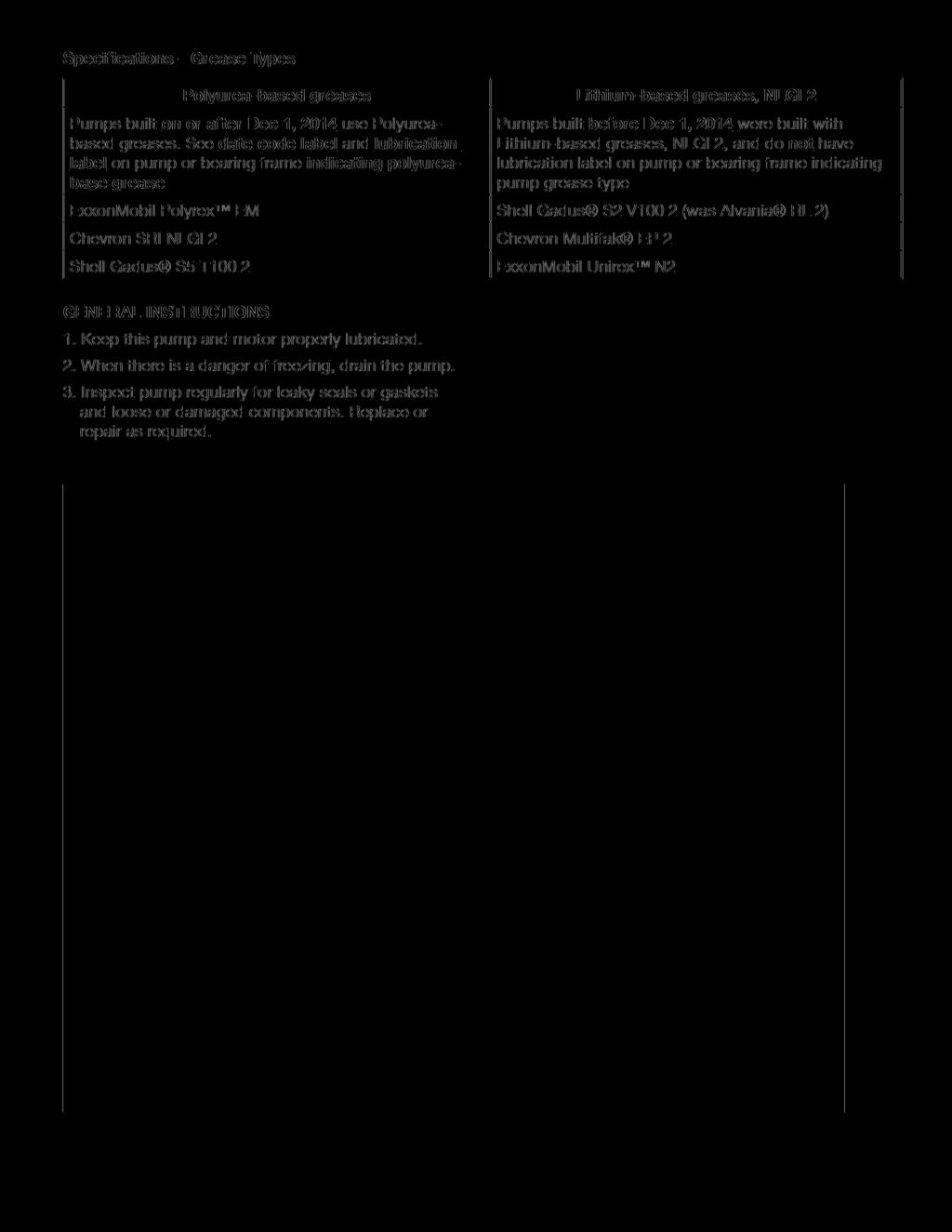
|
|
- Meghan Franklin
- 5 years ago
- Views:
Transcription

1 INSTRUCTION MANUAL P65033 REVISION B INSTALLER: PLEASE LEAVE THIS MANUAL FOR THE OWNER'S USE. Series A-C 2000 Frame Mounted Pumps
2 TABLE OF CONTENTS DESCRIPTION...3 PUMP APPLICATION...3 SAFETY INSTRUCTIONS...3 ELECTRICAL SAFETY...3 THERMAL SAFETY...3 MECHANICAL SAFETY...3 SAFETY DECALS...4 PUMP LOCATION...5 INSTALLATION...6 LEVELING...6 GROUTING...7 SEE ANSI/OSHA COUPLER GUARD REMOVAL/INSTALLATION...7 ALIGNMENT PROCEDURE...7 ANSI/OSHA COUPLER GUARD REMOVAL/INSTALLATION...7 ROTATION...10 PIPING...10 PRIMING AND STARTING...11 BEARING MAINTENANCE...11 GENERAL INSTRUCTIONS...12 SERVICE INSTRUCTIONS...12 IMPELLER REMOVAL...13 DISMANTLING THE STUFFING BOX...13 FRAME DISASSEMBLY...13 CASING WEARING RING REMOVAL (OPTIONAL)...13 ASSEMBLY PROCEDURES...14 FRAME ASSEMBLY...14 STUFFING BOX ASSEMBLY...14 IMPELLER INSTALLATION...15 FINAL ASSEMBLY...15 REPAIR PARTS LIST...17 WARRANTY...19 ORDERING PARTS...24 DEALER SERVICING...24 NOTE The information contained in this book is intended to assist operating personnel by providing information on the characteristics of the purchased equipment. It does not relieve the user of their responsibility of using accepted engineering practices in the installation, operation, and maintenance of this equipment. Any further questions, contact Goulds Water Technology, (847)
3 DESCRIPTION The Series A-C 2000 Frame Mounted Centrifugal Pump is an end suction centerline discharge pump. The Series A-C 2000 Pump s rear pull out construction makes servicing simpler and faster. The hydraulically balanced impellers extend bearing life and assure smoother, quieter operation. PUMP APPLICATION The Series A-C 2000 Pump s available constructions and sizes make it ideal for applications in general industry, water supply, water transfer, condenser, and chilled and hot water circulation. SAFETY INSTRUCTIONS SAFETY INSTRUCTIONS This safety alert symbol will be used in this manual and on the pump safety instruction decals to draw attention to safety related instructions. When used the safety alert symbol means ATTENTION! BECOME ALERT! YOUR SAFETY IS INVOLVED! FAILURE TO FOLLOW THE INSTRUCTIONS MAY RESULT IN A SAFETY HAZARD. Your Series A-C 2000 pump should have the following safety instruction decals located approximately as shown. If the decals are missing or are illegible contact your local Goulds Water Technology representative for a replacement. (Fig. 1) ELECTRICAL SAFETY: WARNING: Electrical Shock Hazard Electrical connections to be made by a qualified electrician in accordance with all applicable codes, ordinances, and good practices. Failure to follow these instructions could result in serious personal injury or death, and property damage. WARNING: Electrical Overload Hazard Three phase motors must have properly sized heaters to provide overload and under voltage protection. Single-phase motors have built-in overload protectors. Failure to follow these instructions could result in serious personal injury or death, and property damage. THERMAL SAFETY: WARNING: Extreme Temperature Hazard If pump, motor, or piping is operating at extremely high or low temperature, guarding or insulation is required. Failure to follow these instructions could result in serious personal injury or death, and property damage. MECHANICAL SAFETY: WARNING: Unexpected Startup Hazard Disconnect and lockout power before servicing. Failure to follow these instructions could result in serious personal injury or death, and property damage. WARNING: Excessive System Pressure Hazard The maximum working pressure of the pump is listed on the nameplate, do not exceed this pressure. Failure to follow these instructions could result in serious personal injury or death, and property damage. WARNING: Excessive Pressure Hazard Volumetric Expansion The heating of water and other fluids causes volumetric expansion. The associated forces may cause failure of system components and release of high temperature fluids. Installing properly sized and located compression tanks and pressure relief valves will prevent this. Failure to follow these instructions could result in serious personal injury or death, and property damage. 3
4 SAFETY INSTRUCTION DECALS 4
5
6 INSTALLATION This pump is built to provide years of service if installed properly and attached to a suitable foundation. A base of concrete weighing 2-1/2 times the weight of the pump is recommended. (Check the shipping ticket for pump weight.) If possible, tie the concrete pad in with the finished floor. Use foundation bolts and larger pipe-sleeves to give room for final bolt location. (Fig. 4) DRILL AND TAPER REAM AFTER ALIGNMENT SHIMS ADJUST TO ALIGN MOTOR TIGHTEN BOLTS BEFORE CHECKING ALIGNMENT 1/2" - 1-1/2" BASEPLATE ASSEMBLY GROUT 8" - 12" TUBE AT LEAST 4" LONG 2 TIMES BOLT DIA. OR 1/2" MIN. SIDE CLEARANCE TO PROVIDE BOLT CLEARANCE HOOK FIG. 4 12" - 18" ALTERNATE BOLT AND WASHER FOUNDATION TO SUIT LOCAL CONDITIONS LEVELING Place the pump on its concrete foundation supporting it with steel wedges or shims totaling 1" in thickness. These wedges or shims should be put on both sides of each anchor-bolt to provide a means of leveling the base. IT IS VERY IMPORTANT THAT THE PUMP- BASE BE SET LEVEL TO AVOID ANY MECHANICAL DIFFICULTIES WITH THE MOTOR OR PUMP. THIS PUMP WAS PROPERLY ALIGNED (IF FURNISHED WITH A MOTOR) AT THE FACTORY. HOWEVER, SINCE ALL PUMP BASES ARE FLEXIBLE THEY MAY SPRING AND TWIST DURING SHIPMENT. DON T PIPE THE PUMP UNTIL IT IS REALIGNED. AFTER PIPING IS COMPLETED AND AFTER THE PUMP IS GROUTED-IN AND BOLTED-DOWN, ALIGN IT AGAIN. IT MAY BE NECESSARY TO RE- ADJUST THE ALIGNMENT FROM TIME TO TIME WHILE THE UNIT AND FOUNDATION ARE NEW. 6
7 GROUTING After the pump has been leveled, securely bolted to the floor, and properly aligned, a good grade of non-shrinking grout should be poured inside the pump base. To hold wedges or shims in place, allow the grout to flow around them. SEE ANSI/OSHA COUPLER GUARD REMOVAL/INSTALLATION (SEE BELOW) ALIGNMENT PROCEDURE NOTE: A flexible coupling will only compensate for small amounts of misalignment. Permissible misalignment will vary with the make of coupling. Consult coupling manufacturer s data when in doubt. Allowances are to be made for thermal expansion during cold alignment, so that the coupling will be aligned at operating temperature. In all cases, a coupling must be in alignment for continuous operation. Even though the coupling may be lubricated, misalignment causes excessive wear, vibration, and bearing loads that result in premature bearing failure and ultimate seizing of the pump. Misalignment can be angular, parallel, or a combination of these, and in the horizontal and vertical planes. Final alignment should be made by moving and shimming the motor on the base plate, until the coupling hubs are within the recommended tolerances measured in total run-out. All measurements should be taken with the pump and motor foot bolts tightened. The shaft of sleeve bearing motors should be in the center of its mechanical float. NOTE: Proper alignment is essential for correct pump operation. This should be performed after base plate has been properly set and grout has dried thoroughly according to instructions. Final alignment should be made by shimming driver only. Alignment should be made at operating temperatures. WARNING: Unexpected Start-up Hazard Disconnect and lock out power before servicing. Failure to follow these instructions could result in serious personal injury or death and property damage. ANSI/OSHA COUPLER GUARD REMOVAL/INSTALLATION WARNING: Unexpected Start-up Hazard Disconnect and lock out power before servicing. Failure to follow these instructions could result in serious personal injury or death and property damage. NOTE: Do not spread the inner and outer guards more than necessary for guard removal or installation. Over spreading the guards may alter their fit and appearance. Removal a. Remove the two capscrews that hold the outer (motor side) coupler guard to the support bracket(s). b. Spread the outer guard and pull it off the inner guard. c. Remove the capscrew that holds the inner guard to the support bracket. d. Spread the inner guard and pull it over the coupler. Installation a. Check coupler alignment before proceeding. Correct if necessary. b. Spread the inner guard and place it over the coupler. c. With the inner guard straddling the support bracket, install a capscrew through the hole (or slot) in the support bracket and guard located closest to the pump. Do not tighten the capscrew. d. Spread the outer guard and place it over the inner guard. e. Install the outer guard capscrews by following the step stated below which pertains to your particular pump: i. For pumps with a motor saddle support bracket: Ensure the outer guard is straddling the support arm, and install but do not tighten the two remaining capscrews. ii. For pumps without a motor saddle support bracket: Insert the spacer washer between the holes located closest to the motor in the outer guard, and install, but do not tighten, the two remaining capscrews. 7
8 f. Position the outer guard so it is centered around the shaft, and so there is less than 1/4" of the motor shaft exposed. On guards that utilize a slotted support bracket, the inner guard will have to be ANSI/OSHA Coupling Guard Exploded View For Typical Fire Pump Installat positioned so there is only 1/4" of the pump shaft exposed. g. Holding the guard in this position, tighten the three capscrews. INNER GUARD OUTER GUARD ATTACH SUPPORT BRACKET TO BEARING HOUSING SUPPORT BRACKET LOCATE SUPPORT ARM BETWEEN OUTER GUARD ENDS. ALIGN THE ARM WITH HOLES IN THE OUTER GUARD AND HOLES IN THE SADDLE BRACKET. NUT LOCKWASHER CAPSCREW FLAT WASHER SPACER WASHER BRACKET SUPPORT ATTACHED INSIDE HERE IN LINE WITH BOLT BRACKET SUPPORT MOTOR SADDLE BRACKET ATTACH TO MOTOR SADDLE THIS OPTION USED IN PLACE OF SPACER WHERE OVERALL LENGTH OF GUARD EXCEEDS 12 INCHES OR GUARD WITH IS OVER 10 INCHES ACROSS THE FLATS. FIG. 5 Method 1 Straight Edge Alignment for Standard Sleeve Type Coupler with Black Rubber Insert (See Fig. 5A) Proceed with this method only if satisfied that face and outside diameters of the coupling halves are square and concentric with the coupling borers. If this condition does not exist or elastomeric couplings do not make this method convenient, use Method Check angular misalignment using a micrometer or caliper. Measure from the outside of one flange to the outside of the opposite flange at four points 90 apart. DO NOT ROTATE COUPLER. Misalignment up to 1/64" per inch of coupler radius is permissible. 2. At four points 90 apart (DO NOT ROTATE COUPLER), measure the parallel coupler misalignment by laying a 8 straight edge across one coupler half and measuring the gap between the straight edge and opposite coupler half. Up to a 1/64" gap is permissible. STRAIGHT EDGE FEELER GAGE ANGULAR ALIGNMENT STRAIGHT EDGE INCORRECT ALIGNMENT FEELER GAGE PARALLEL ALIGNMENT CORRECT ALIGNMENT FIG. 5A CHECKING ALIGNMENT (METHOD 1)
9 Method 2- For Orange Hytrel Insert, 3500 Operation, or All Other Coupler Types Except as Noted Below (See Fig. 5B) a. Make sure each hub is secured to its respective shaft and that all connecting and/or spacing elements are removed at this time. b. The gap between the coupling hubs is set by the manufacturer before the units are shipped. However, this dimension should be checked. (Refer to the coupling manufacturer s specifications supplied with the unit.) c. Scribe index lines on coupling halves as shown in Fig. 5B. d. Mount dial indicator on one hub as shown for parallel alignment. Set dial to zero. e. Turn both coupling halves so that index lines remain matched. Observe dial reading to see whether driver needs adjustment (See paragraph i below). f. Mount dial indicator on one hub as shown for angular alignment. Set dial to zero. g. Turn both coupling halves so that index lines remain matched. Observe dial reading to see whether driver needs adjustment (See paragraph i below). h. Assemble coupling. Tighten all bolts and set screw(s). It may be necessary to repeat steps c through f for a final check. i. For single element couplings, a satisfactory parallel misalignment is 0.004"T.I.R., while a satisfactory angular misalignment is 0.004"T.I.R. per inch of radius R (See Fig. 5B). PARALLEL ALIGNMENT ANGULAR ALIGNMENT DIAL INDICATOR INDEX LINE RESILIENT SEPARATOR DIAL INDICATOR FIG. 5B CHECKING ALIGNMENT (METHOD 2) 9
10 Final Alignment Final alignment cannot be accomplished until the pump has been operated initially for a sufficient length of time to attain operating temperature. When normal operating temperature has been attained, secure the pump to re-check alignment and compensate for temperature accordingly. See Alignment Section. WARNING: Rotating Components Hazard Do not operate pump without all guards in place. Failure to follow these instructions could result in serious personal injury or death and property damage. WARNING: Coupling Failure Do not operate pump with coupling out of alignment. Ensure final coupling alignment is within the values stated above or according to the coupling manufacturer s instructions. Coupling, pump, or driver failure may occur. Failure to follow these instructions could result in serious personal injury or death and property damage. Due to the different types of couplers available for your Series A-C 2000 pump, refer to coupler manufacturer's instructions for alignment values and additional instructions. ROTATION Pump rotation is clockwise when viewed from back of the motor. An arrow is also located on the pump to show the direction of rotation. PIPING Always install a section of straight pipe between the suction side of the pump and first elbow. This reduces turbulence of the suction by straightening out the flow of liquid before it enters the pump. The length should be equal to ten times the diameter of the pipe. Be sure to eliminate any pipe-strain on the pump. Support the suction and discharge pipes independently by use of pipe hangers near the pump. Line up the vertical and horizontal piping so that the bolt-holes in the pump flanges match the bolt-holes in the pipe flanges. DO NOT ATTEMPT TO SPRING THE SUCTION OR DISCHARGE LINES INTO POSITION. Coupling and bearing wear will result if suction or discharge lines are forced into position. The code for Pressure Piping (A.S.A.B. 31.1) lists many types of supports available for various applications. As a rule, ordinary wire or band hangers are not adequate to maintain alignment. It is very important to provide a strong, rigid support for the suction and discharge lines. Where considerable temperature changes are anticipated, fittings for absorbing expansion should be installed in the system in such a way as to avoid strain on the pump. On an open-system with a suction-lift, use a foot-valve of equal or greater area than the pump suction piping. Prevent clogging by using a strainer at the suction inlet next to the foot-valve. The strainer should have an area three times that of the suction pipe with a mesh hole diameter of no less than 1/4". When using an isolation base, flexible piping should be used on both the suction and discharge sides of the pump. A check valve installed in the discharge line will serve to protect the pump from water hammer. Also install an isolation valve for servicing and for throttling. NOTES: 1. The pipeline should have isolation valves around the pump and have a drain valve in the suction pipe. 2. When installing connections to a threaded pump housing the use of PTFE tape sealer or a high quality thread sealant is recommended. 10
11
12 12
13 5. Remove the O-ring ( ) from the stuffing box cover and inspect for damage. Replace if necessary. IMPELLER REMOVAL 1. Lock the coupling end of the shaft in a padded vise. 2. Remove the impeller nut ( ). To do this, turn the impeller nut in the same direction in which the impeller rotates (counterclockwise viewing from the suction inlet). 3. Pull the impeller ( ) from the shaft and remove the impeller key ( ). DISMANTLING THE STUFFING BOX A. Pumps with Mechanical Seals 1. Remove spacer sleeve ( ). 2. Remove the two nuts holding the gland ( ) to the stuffing box ( ). 3. Pull the stuffing box cover off the shaft assembly. NOTE: On the larger Series A-C 2000 pumps, it will be necessary to remove the capscrews holding the stuffing box cover to the frame. The mechanical seal ( ) should now be exposed on the shaft sleeve. (In some cases, the shaft sleeve may come off the shaft with the stuffing box cover. If this happens, gently press or pull the shaft sleeve and mechanical seal from the stuffing box toward frame side of the stuffing box cover.) This will expose the mechanical seal as above. 4. Remove the seal from the shaft sleeve, examine for damage, and if necessary replace. 5. Remove the gland ( ), shaft sleeve ( ), and the deflector ( ) from the pump shaft. A puller may be used to remove the shaft sleeve if it does not slide off the pump shaft easily. B. Pumps with Packed Stuffing Box 1. Loosen packing gland ( ) by loosening the two gland retaining nuts. 2. Pull the stuffing box cover, gland, and packing from the shaft. packing rings ( ) and, where applicable, the seal cage ( ) from the stuffing box. A standard packing hook is recommended for removing the pack and seal cage. 4. Remove the packing base ring. FRAME DISASSEMBLY 1. Remove bearing caps ( and ). 2. Remove snap ring ( ) from the outboard bearing housing. 3. Press the shaft ( ), outboard bearing ( ), and inboard bearing ( ) toward the motor side of the frame until the outboard bearing clears the frame s outboard bearing housing. 4. Using a suitable pair of snap ring pliers, remove snap ring ( ) from the outboard bearing housing. (Flat snap ring located on the inside of the outboard bearing housing.) 5. Finish removing the shaft and outboard bearing. 6. Remove the snap ring ( ) from the outboard end (motor end) of the pump shaft. 7. Using a suitable bearing press, remove the inboard bearing ( ) and the outboard bearing ( ) from the pump shaft ( ). CASING WEARING RING REMOVAL (OPTIONAL) The optional wearing rings are removed from the casing and stuffing box cover by the following method: 1. Drill two axial holes into each wearing ring approximately 180 apart being careful not to drill into casing or stuffing box cover. 2. Split the wearing rings using a chisel. 3. Remove the parts from the wearing ring fit. This completes the disassembly of the Series A-C 2000 frame mounted pump. 3. Remove the two gland retaining nuts and remove the gland ( ). Remove the 13
14 ASSEMBLY PROCEDURES FRAME ASSEMBLY 1. Press the outboard bearing ( ) onto the motor side of the pump shaft ( ). NOTE: When pressing bearings onto the shaft, press only against the inner race. 2. Install snap ring ( ) on the pump shaft with the tapered edge away from the bearing (outboard side of outboard bearing). 3. Place snap ring ( , flat snap ring) over the pump shaft ( ) positioning the snap ring between the two bearing shoulders. NOTE: There are two snap rings that go into the outboard bearing housing: snap rings ( and ). Snap ring ( ) is flat and goes into the inside snap ring groove, and snap ring ( ) is tapered and goes into the outside snap ring groove. 4. Press inboard bearing ( ) onto the inboard side (pump side) of the pump shaft. 5. Press the inboard end (pump end) of the shaft-bearing assembly into the outboard end (motor end) of the pump frame. Press the unit toward the pump side of the frame until the inboard bearing clears the outboard bearing housing. FIG. 6 Tapered Snap Rings 6. Using a suitable pair of snap ring pliers, place snap ring ( , located on the pump shaft between the bearings) into the inside snap ring groove of the outboard bearing housing Continue pressing the shaft and bearing assembly into the frame until the outboard bearing ( ) seats firmly against snap ring ( ) inside the outboard bearing housing. 8. Place snap ring ( ) in the outside snap ring groove of the outboard bearing housing (tapered edge away from bearing). 9. Install bearing caps ( and ) onto both ends of the pump frame. STUFFING BOX ASSEMBLY NOTE: There are two pipe taps on the stuffing box; one closest to the gland, and one furthest away from the gland. If the pump is equipped with mechanical seals, the stuffing box cover should be positioned with the pipe tap closest to the gland on top. If the pump is equipped with packing, the stuffing box cover should be positioned so the pipe tap furthest away from the gland is on top. For ease of assembly, install pipe fittings in the stuffing box pipe taps before assembling stuffing box on the frame. A. Pumps with Mechanical Seals 1. Install the two gland retaining studs ( ) into the stuffing box cover. 2. Install the rotating and stationary elements of the mechanical seal ( ) on the shaft sleeve ( ) being certain that the two wearing surfaces face each other. Position the seal on the sleeve according to the G dimension found in Fig Place seal spring retainer into stuffing box. 4. Place seal spring into stuffing box. 5. Place sleeve and seal assembly into stuffing box with rotating half of seal installed closest to the impeller. 6. Install the seal gland ( ) (flat side toward stuffing box) on the stuffing box using the gland studs ( ) and gland nuts ( ). Tighten gland nuts evenly until the gland is approximately 1/8" from the stuffing box. 14
15 STUFFING BOX IMPELLER HUB B. Pumps with Packed Stuffing Boxes 1. Slide deflector ( ) onto the pump shaft. 2. Slide the packing gland ( ) onto the pump shaft (flat side toward frame). FIG. 7 G Setting Dimensions Shaft Sleeve OD (inches) G (inches) Slide the deflector ring ( ) onto the motor shaft. 8. Slide the stuffing box cover, seal, and sleeve assembly onto the frame shaft being certain the stuffing box is closest to the frame. To prevent any leakage, use silicone sealant between the shaft and shaft sleeve. G 3. Slide the shaft sleeve ( ) onto the pump shaft. To prevent leakage, use silicone sealant between the shaft and shaft sleeve. 4. Place the packing base ring ( ) into the stuffing box. Slide the stuffing box cover over the pump shaft, and, if applicable, bolt the stuffing box to the frame using capscrews ( ). 5. Install the packing ( ) and, if applicable, the seal cage ( ) into the stuffing box being sure to stagger the joints. 6. Tighten the packing gland nuts to seat the packing. Loosen the nuts to permit the packing to expand then retighten finger tight. 9. If applicable, bolt the frame to the stuffing box using capscrews ( ). IMPELLER INSTALLATION 1. If the pump is equipped with mechanical seals, slide the spacer sleeve ( ) over the shaft sleeve and into the stuffing box. 2. Install the impeller key into the keyway on the impeller side of the pump shaft. 3. Slide the pump impeller ( ) onto the pump shaft. 4. Screw the impeller nut ( ) onto the pump shaft until finger tight. Clamp the coupling end of the pump shaft in a padded vise, and tighten (clockwise as viewed from the suction inlet) the impeller nut to ft. lbs. 5. For pumps with mechanical seals, tighten gland evenly against the stuffing box. FINAL ASSEMBLY 1. Place the O-ring casing seal ( ) around the O-ring seat on the stuffing box cover. 2. Carefully slide the frame assembly into the casing being sure not to pinch the O-ring. Insert the capscrews ( ) through the frame and into the casing (the large Series A-C 2000 pumps use capscrews and clamping lugs ( ) to hold the frame to the casing). Tighten opposite 3. capscrews evenly around the frame until the stuffing box has been drawn evenly into the casing. Then alternately torque each capscrew to 25 lbs. Secure frame foot to pump base. 4. If necessary, connect the suction and discharge piping to the pump. 5. Connect the flush line to the stuffing box. 15
16 6. Align the pump to the motor as instructed. 7. Connect the pump to the motor. Reinstall the coupling guard and drain plugs. Close drain valve. 8. Connect the power to the motor. CHECK THE MOTOR ROTATION. 9. Open isolation valves, inspect pump for leaks. If not leaking, return pump to service. NOTE FOR PACKED PUMPS: Final adjustment of the gland nuts must be done with the pump running. Allow 30 minutes between adjustments. Tightening the nuts too quickly can cause damage to the packing and sleeve. A good adjustment should allow approximately one (1) drip per second. This completes the assembly of the Series A-C 2000 pump. NOTE: All pumps are shipped with coupling guards. Coupling guards must be in place before operating pump. WARNING Do not operate without all guards in place. Failure to follow these instructions could result in injury or death. 16
17 ALTERNATE CLAMPING METHOD INTERNAL OR EXTERNAL FLUSH PUMP WITH PACKING (PLUGGED) PUMP WITH PACKING OPTIONAL SEAL CAGE (INTERNAL OR EXTERNAL) PUMP WITH OPTIONAL CASING WEAR RINGS 17
18 REPAIR PARTS LIST Cat. No. Part Name Quantity Cat. No. Part Name Quantity Shaft Sleeve Bearing Cap, Outboard Deflector Bearing, Inboard Spacer Sleeve Bearing, Outboard Frame Foot Assembly Snap Ring, Inboard Bearing Housing By-Pass Piping Kit Snap Ring, Outboard Bearing Housing Capscrews Miscellaneous Frame 1 With Lugs Snap Ring, Shaft Grease Fitting, Inboard Gland Grease Fitting Outboard Ring Packing Base Pipe Plugs 2 Without By-Pass Mechanical Seal Gland Nut Key, Coupling Gland Stud Casing Pipe Plug Stuffing Box Cover 1 Without By-Pass O-Ring, Casing Seal Packing Clamping Lug 8 With Seal Cage Impeller Impeller Nut 1 OPTIONAL COMPONENTS Key, Impeller By-Pass Piping Kit, Seal Cage Shaft Wear Ring, Suction Bearing Cap, Inboard Wear Ring, Stuffing Box Seal Cage 1 18
19 COMMERCIAL WARRANTY Warranty. For goods sold to commercial buyers, Seller warrants the goods sold to Buyer hereunder (with the exception of membranes, seals, gaskets, elastomer materials, coatings and other wear parts or consumables all of which are not warranted except as otherwise provided in the quotation or sales form) will be (i) be built in accordance with the specifications referred to in the quotation or sales form, if such specifications are expressly made a part of this Agreement, and (ii) free from defects in material and workmanship for a period of one (1) year from the date of installation or eighteen (18) months from the date of shipment (which date of shipment shall not be greater than thirty (30) days after receipt of notice that the goods are ready to ship), whichever shall occur first, unless a longer period is specified in the product documentation (the Warranty ). Except as otherwise required by law, Seller shall, at its option and at no cost to Buyer, either repair or replace any product which fails to conform with the Warranty provided Buyer gives written notice to Seller of any defects in material or workmanship within ten (10) days of the date when any defects or non-conformance are first manifest. Under either repair or replacement option, Seller shall not be obligated to remove or pay for the removal of the defective product or install or pay for the installation of the replaced or repaired product and Buyer shall be responsible for all other costs, including, but not limited to, service costs, shipping fees and expenses. Seller shall have sole discretion as to the method or means of repair or replacement. Buyer s failure to comply with Seller s repair or replacement directions shall terminate Seller s obligations under this Warranty and render the Warranty void. Any parts repaired or replaced under the Warranty are warranted only for the balance of the warranty period on the parts that were repaired or replaced. Seller shall have no warranty obligations to Buyer with respect to any product or parts of a product that have been: (a) repaired by third parties other than Seller or without Seller s written approval; (b) subject to misuse, misapplication, neglect, alteration, accident, or physical damage; (c) used in a manner contrary to Seller s instructions for installation, operation and maintenance; (d) damaged from ordinary wear and tear, corrosion, or chemical attack; (e) damaged due to abnormal conditions, vibration, failure to properly prime, or operation without flow; (f) damaged due to a defective power supply or improper electrical protection; or (g) damaged resulting from the use of accessory equipment not sold or approved by Seller. In any case of products not manufactured by Seller, there is no warranty from Seller; however, Seller will extend to Buyer any warranty received from Seller s supplier of such products. THE FOREGOING WARRANTY IS EXCLUSIVE AND IN LIEU OF ANY AND ALL OTHER EXPRESS OR IMPLIED WARRANTIES, GUARANTEES, CONDITIONS OR TERMS OF WHATEVER NATURE RELAT- ING TO THE GOODS PROVIDED HEREUNDER, INCLUDING WITHOUT LIMITATION ANY IMPLIED WARRANTIES OF MERCHANTABILITY AND FITNESS FOR A PARTICULAR PURPOSE, WHICH ARE HEREBY EXPRESSLY DISCLAIMED AND EXCLUDED. EXCEPT AS OTHERWISE REQUIRED BY LAW, BUYER S EXCLUSIVE REMEDY AND SELLER S AGGREGATE LIABILITY FOR BREACH OF ANY OF THE FOREGOING WARRANTIES ARE LIMITED TO REPAIRING OR REPLACING THE PRODUCT AND SHALL IN ALL CASES BE LIMITED TO THE AMOUNT PAID BY THE BUYER FOR THE DEFECTIVE PRODUCT. IN NO EVENT SHALL SELLER BE LIABLE FOR ANY OTHER FORM OF DAMAGES, WHETH- ER DIRECT, INDIRECT, LIQUIDATED, INCIDENTAL, CONSEQUENTIAL, PUNITIVE, EXEMPLARY OR SPECIAL DAMAGES, INCLUDING BUT NOT LIMITED TO LOSS OF PROFIT, LOSS OF ANTICIPATED SAVINGS OR REVENUE, LOSS OF INCOME, LOSS OF BUSINESS, LOSS OF PRODUCTION, LOSS OF OPPORTUNITY OR LOSS OF REPUTATION.
20 LIMITED CONSUMER WARRANTY Warranty. For goods sold for personal, family or household purposes, Seller warrants the goods purchased hereunder (with the exception of membranes, seals, gaskets, elastomer materials, coatings and other wear parts or consumables all of which are not warranted except as otherwise provided in the quotation or sales form) will be free from defects in material and workmanship for a period of one (1) year from the date of installation or eighteen (18) months from the product date code, whichever shall occur first, unless a longer period is provided by law or is specified in the product documentation (the Warranty ). Except as otherwise required by law, Seller shall, at its option and at no cost to Buyer, either repair or replace any product which fails to conform with the Warranty provided Buyer gives written notice to Seller of any defects in material or workmanship within ten (10) days of the date when any defects or non-conformance are first manifest. Under either repair or replacement option, Seller shall not be obligated to remove or pay for the removal of the defective product or install or pay for the installation of the replaced or repaired product and Buyer shall be responsible for all other costs, including, but not limited to, service costs, shipping fees and expenses. Seller shall have sole discretion as to the method or means of repair or replacement. Buyer s failure to comply with Seller s repair or replacement directions shall terminate Seller s obligations under this Warranty and render this Warranty void. Any parts repaired or replaced under the Warranty are warranted only for the balance of the warranty period on the parts that were repaired or replaced. The Warranty is conditioned on Buyer giving written notice to Seller of any defects in material or workmanship of warranted goods within ten (10) days of the date when any defects are first manifest. Seller shall have no warranty obligations to Buyer with respect to any product or parts of a product that have been: (a) repaired by third parties other than Seller or without Seller s written approval; (b) subject to misuse, misapplication, neglect, alteration, accident, or physical damage; (c) used in a manner contrary to Seller s instructions for installation, operation and maintenance; (d) damaged from ordinary wear and tear, corrosion, or chemical attack; (e) damaged due to abnormal conditions, vibration, failure to properly prime, or operation without flow; (f) damaged due to a defective power supply or improper electrical protection; or (g) damaged resulting from the use of accessory equipment not sold or approved by Seller. In any case of products not manufactured by Seller, there is no warranty from Seller; however, Seller will extend to Buyer any warranty received from Seller s supplier of such products. THE FOREGOING WARRANTY IS PROVIDED IN PLACE OF ALL OTHER EXPRESS WARRANTIES. ALL IMPLIED WARRANTIES, INCLUDING BUT NOT LIMITED TO THE IMPLIED WARRANTIES OF MERCHANTABILITY AND FITNESS FOR A PARTICULAR PURPOSE, ARE LIMITED TO ONE (1) YEAR FROM THE DATE OF INSTALLATION OR EIGHTEEN (18) MONTHS FROM THE PRODUCT DATE CODE, WHICHEVER SHALL OCCUR FIRST. EXCEPT AS OTHERWISE REQUIRED BY LAW, BUYER S EXCLUSIVE REMEDY AND SELLER S AGGREGATE LIABILITY FOR BREACH OF ANY OF THE FORE- GOING WARRANTIES ARE LIMITED TO REPAIRING OR REPLACING THE PRODUCT AND SHALL IN ALL CASES BE LIMITED TO THE AMOUNT PAID BY THE BUYER FOR THE DEFECTIVE PRODUCT. IN NO EVENT SHALL SELLER BE LIABLE FOR ANY OTHER FORM OF DAMAGES, WHETHER DIRECT, INDIRECT, LIQUIDATED, INCIDENTAL, CONSEQUENTIAL, PUNITIVE, EXEMPLARY OR SPECIAL DAMAGES, INCLUDING BUT NOT LIMITED TO LOSS OF PROFIT, LOSS OF ANTICIPATED SAVINGS OR REVENUE, LOSS OF INCOME, LOSS OF BUSINESS, LOSS OF PRODUCTION, LOSS OF OPPOR- TUNITY OR LOSS OF REPUTATION.
21 Some states do not allow limitations on how long an implied warranty lasts, so the above limitation may not apply to you. Some states do not allow the exclusion or limitation of incidental or consequential damages, so the above exclusions may not apply to you. This warranty gives you specific legal rights, and you may also have other rights which may vary from state to state. To make a warranty claim, check first with the dealer from whom you purchased the product or call the following number for the name and location of the nearest dealer providing warranty service. For Goulds Water Technology contact For all other products, contact
22 NOTES 22
23 NOTES 23
24 Xylem Inc N. Austin Avenue Morton Grove, Illinois Phone: (847) Fax: (847) Goulds is a registered trademark of Goulds Pumps, Inc. and is used under license. Aquavar is a trademark of Xylem, Inc. or one of its subsidiaries Xylem, Inc. P65033B November 2014
INSTRUCTION MANUAL P81630 INSTALLER: PLEASE LEAVE THIS MANUAL FOR THE OWNER S USE. Series VSC and VSCS Base Mounted Centrifugal Pumps
 INSTRUCTION MANUAL P81630 Revision E INSTALLER: PLEASE LEAVE THIS MANUAL FOR THE OWNER S USE. Series VSC and VSCS Base Mounted Centrifugal Pumps (TO BE USED IN CONJUNCTION WITH VSC PARTS LIST CONTAINING
Suction Diffuser INSTRUCTION MANUAL
 Suction Diffuser INSTRUCTION MANUAL Table of Contents Table of Contents Introduction and Safety...2 Introduction...2 Safety...2 Safety terminology and symbols... 2 User safety... 3 Environmental safety...4
INSTRUCTION MANUAL. Suction Diffuser Plus
 INSTRUCTION MANUAL Suction Diffuser Plus Table of Contents Table of Contents Introduction and Safety...2 Introduction...2 Safety...2 Safety terminology and symbols... 2 User safety... 3 Environmental
INSTRUCTION MANUAL V REV B. Circuit Sentry TM Flo-Setter II Balance & Commissioning Valves with NPT Connections
 INSTRUCTION MANUAL V1002552 REV B Circuit Sentry TM Flo-Setter II Balance & Commissioning Valves with NPT Connections Table of Contents Table of Contents 1 Introduction and Safety...2 1.1 Introduction...
TECHNICAL SERVICE MANUAL
 Electronic copies of the most current TSM issue can be found on the Viking Pump website at www.vikingpump.com TECHNICAL SERVICE MANUAL VIKING HELICAL GEAR REDUCERS A, B, AND C SIZES SECTION PAGE ISSUE
INSTRUCTION, INSTALLATION, MAINTENANCE AND REPAIR MANUAL MODEL 3310
 SECTION 6 ITEM 3310 DATED JUNE 1, 2007 INSTRUCTION, INSTALLATION, MAINTENANCE AND REPAIR MANUAL 6 MODEL 3310 IMPORTANT NOTE TO INSTALLER: This manual contains important information about the installation,
TECHNICAL SERVICE MANUAL
 Electronic copies of the most current TSM issue can be found on the Viking Pump website at www.vikingpump.com TECHNICAL SERVICE MANUAL SECTION TSM 610 Viking Helical Gear Reducers a, b, and c sizes PAGE
INSTRUCTION, INSTALLATION, MAINTENANCE AND REPAIR MANUAL MODELS 3341 AND 3344 END SUCTION PUMPS
 SECTION 6 ITEM 3340 DATED JULY 2005 SUPERSEDES SECTION 6 ITEM 3340 DATED JANUARY 2004 INSTRUCTION, INSTALLATION, MAINTENANCE AND REPAIR MANUAL MODELS 3341 AND 3344 END SUCTION PUMPS 6 IMPORTANT NOTE TO
MetroPrime 22MPC Self-Priming Centrifugal Pump
 Page 1 of 6 prevent priming or reduce pump capacity. OPERATION The 22 MPC-Metropolitan Pump is a self-priming centrifugal pump and only requires priming prior to its initial start. The pump will retain
INSTRUCTION MANUAL AC8585 REVISION D INSTALLER: PLEASE LEAVE THIS MANUAL FOR THE OWNER S USE Series Base Mounted Centrifugal Fire Pumps
 INSTRUCTION MANUAL AC8585 REVISION D INSTALLER: PLEASE LEAVE THIS MANUAL FOR THE OWNER S USE. 9100 Series Base Mounted Centrifugal Fire Pumps TABLE OF CONTENTS DESCRIPTION...3 OPERATIONAL LIMITS...3 MAXIMUM
TECHNICAL SERVICE MANUAL INSTALLATION, START UP, TROUBLESHOOTING, SERIES SG-04, SG-05 & SG-07 spur gear PUMPS
 Electronic copies of the most current TSM issue can be found on the Viking Pump website at www.vikingpump.com TECHNICAL SERVICE MANUAL SECTION TSM 340 PAGE 1 OF 10 ISSUE G INSTALLATION, START UP, TROUBLESHOOTING,
SERIES PC INSTRUCTION AND OPERATION MANUAL
 MEGGA SERIES PC INSTRUCTION AND OPERATION MANUAL Models PCT and PCF Close-coupled and frame-mounted single-stage horizontal end-suction pumps. WARNING: Read this manual before installing or operating this
Guardian Steel Gear Shaft Coupling
 Guardian Steel Gear Shaft Coupling P-8609-GC GUA-MRK-DOC-026 Service & Installation Instructions TABLE OF CONTENTS NOTICES AND WARNINGS PAGE 2 SECTION 1 COUPLING OVERVIEW PAGE 3 SECTION 2 TOOLS/MATERIALS
SUMMIT PUMP Horizontal End Suction Pump Close Coupled and Frame Mounted
 SUMMIT PUMP Horizontal End Suction Pump Close Coupled and Frame Mounted Installation, Operation, and Maintenance Manual 2014 by Summit Pump, Inc. All rights reserved. WARRANTY Pumping units assembled
MODELS 3801 AND 3804 END SUCTION PUMPS INSTRUCTION, INSTALLATION, MAINTENANCE AND REPAIR MANUAL. Model Model 3804
 Model 3801 Model 3804 MODELS 3801 AND 3804 END SUCTION PUMPS INSTRUCTION, INSTALLATION, MAINTENANCE AND REPAIR MANUAL NOTE! To the installer: Please make sure you provide this manual to the owner of the
900 SERIES SPLIT CASE FIRE PUMP REPAIR PARTS INDEX
 900 SERIES SPLIT CASE FIRE PUMP REPAIR PARTS INDEX Read and understand the pump and motor instructions before attempting to install, disassemble or repair the pump. Part # AF-03-326 2015 Pentair Ltd. 01/30/15
TECHNICAL SERVICE MANUAL
 Electronic copies of the most current TSM issue can be found on the Viking Pump website at www.vikingcom TECHNICAL SERVICE MANUAL abrasive liquid pumps SERIES 4625 SIZES f - fh SECTION TSM 410.1 PAGE 1
PRODUCT OBSOLETED 4Q16
 Electronic copies of the most current TSM issue can be found on the Viking Pump website at www.vikingcom TECHNICAL SERVICE MANUAL abrasive liquid pumps SERIES 4625 SIZES f - fh SECTION TSM 410.1 PAGE 1
Procedure to Install the New Autogap components in ER-1225 and ER825 Brake with inverted Armature Hub
 Procedure to Install the New Autogap components in ER-15 and ER85 Brake with inverted P-30-1 819-0376 Installation & Operating Instructions Contents Introduction........................... Kit Parts List..........................
Domestic Pump 2 NPSH Horizontal Pumps Series HB17, HB35, DB, DB-F
 INSTRUCTION MANUAL DN0141 REVISION E Domestic Pump 2 NPSH Horizontal Pumps Series HB17, HB35, DB, DB-F TM TM Series HB and DB only TM Series DB-F only TM DESCRIPTION These horizontal end suction pumps
AT Clutch Major Service Sizes 25, 55, 115
 P-1404 819-0324 AT Clutch Major Service Sizes 25, 55, 115 Installation Instructions Contents Introduction............................ 2 Warranty....................... back cover Failure to follow these
Single-Position Detent Clutch DC Series. (i) MTY (81) MEX (55) QRO (442)
 MTY (81) MEX (55) QRO (442)") Single-Position Detent Clutch DC Series (i) FORM NO. L-2017-A-001 In accordance with Nexen s established policy of constant product improvement, the specifications contained in this manual are subject
Single-Position Detent Clutch DC Series (i) FORM NO. L-2017-A-001 In accordance with Nexen s established policy of constant product improvement, the specifications contained in this manual are subject
TECHNICAL SERVICE MANUAL
 Electronic copies of the most current TSM issue can be found on the Viking Pump website at www.vikingpump.com TECHNICAL SERVICE MANUAL industrial heavy duty motor speed pumps SERIES 4076 AND 4176 SIZES
Guardian Taper Grid Shaft Coupling
 Guardian Taper Grid Shaft Coupling P-8608-GC GUA-MRK-DOC-025 Service & Installation Instructions TABLE OF CONTENTS NOTICES AND WARNINGS PAGE 2 SECTION 1 COUPLING OVERVIEW PAGE 3 SECTION 2 TOOLS/MATERIALS
Marlow Series Cast Iron Swimming Pool Pumps
 INSTRUCTION MANUAL SECTION 360A AC1683 REVISION C INSTALLER: PLEASE LEAVE THIS MANUAL FOR THE OWNER'S USE. Marlow Series Cast Iron Swimming Pool Pumps 3B28EC 3B32EC PLEASE FILL IN DATA FROM YOUR PUMP NAMEPLATE
TECHNICAL SERVICE MANUAL
 Electronic copies of the most current TSM issue can be found on the Viking Pump website at www.vikingpump.com TECHNICAL SERVICE MANUAL HEAVY-DUTY Stainless steel BRACKET MOUNTED PUMPS SERIES 127 AND 4127
BC Brake Caliper. (i) MEX (55) QRO (442) MTY (81) DIST. AUTORIZADO
 MEX (55) QRO (442) MTY (81) DIST. AUTORIZADO") MEX (55) 5 6 QRO (44) 95 7 60 MTY () 54 0 BC Brake Caliper (i) FORM NO. L-0066-B-040 In accordance with Nexen s established policy of constant product improvement, the specifications contained in this
MEX (55) 5 6 QRO (44) 95 7 60 MTY () 54 0 BC Brake Caliper (i) FORM NO. L-0066-B-040 In accordance with Nexen s established policy of constant product improvement, the specifications contained in this
Watts Series CSM-91. Grooved/Flanged Flow Measurement/Balancing Valves. Installation and Operating Instructions. Table of Contents. 1.
 Watts Series CSM-9 Grooved/Flanged Flow Measurement/Balancing Valves Installation and Operating Instructions IS-CSM-9 Table of Contents Item Description Page. Installation of Valve Angle Design 2. Installation
V400D VERIS Verabar (Double Rod) Installation and Maintenance Manual
 Installation and Maintenance Manual") V400D VERIS Verabar (Double Rod) Installation and Maintenance Manual 168-EN Please read and save these instructions Contents General Safety Information...3 Product Information...3 Section 1: Scope...3
V400D VERIS Verabar (Double Rod) Installation and Maintenance Manual 168-EN Please read and save these instructions Contents General Safety Information...3 Product Information...3 Section 1: Scope...3
INSTRUCTION MANUAL AC2516 REVISION D INSTALLER: PLEASE LEAVE THIS MANUAL FOR THE OWNER S USE. Series 1580 In-Line Mounted Centrifugal Fire Pumps
 INSTRUCTION MANUAL AC2516 REVISION D INSTALLER: PLEASE LEAVE THIS MANUAL FOR THE OWNER S USE. Series 1580 In-Line Mounted Centrifugal Fire Pumps PUMP LOCATION Locate the pump so there is sufficient room
INSTRUCTIONS Installation Operation Repair
 Peerless Pump Company 2005 Dr. M.L. King Jr. Street, P.O. Box 7026, Indianapolis, IN 46207-7026, USA Telephone: (317) 925-9661 Fax: (317) 924-7338 www.peerlesspump.com www.epumpdoctor.com INSTRUCTIONS
TECHNICAL SERVICE MANUAL
 TECHNICAL SERVICE MANUAL VIKING HELICAL GEAR REDUCERS "A", "B", AND "C" SIZES SECTION TSM 610 PAGE 1 OF 9 ISSUE E CONTENTS Special Information 2 Lubrication 2 Installation 3 Operation 3 Disassembly 3 Assembly
INSTRUCTION MANUAL AC2515 REVISION D INSTALLER: PLEASE LEAVE THIS MANUAL FOR THE OWNER S USE Series Centrifugal Pumps
 INSTRUCTION MANUAL AC2515 REVISION D INSTALLER: PLEASE LEAVE THIS MANUAL FOR THE OWNER S USE. 8100 Series Centrifugal Pumps TABLE OF CONTENTS INTRODUCTION...3 PUMP IDENTIFICATION...3 SAFETY INSTRUCTION...4
Product/ Title Guardian Super Flex Shaft Coupling Product/ Title
 Product/ Title Guardian Super Flex Shaft Coupling Product/ Title GUA-MRK-DOC-027 P-XXXX-GC Service&&Installation Installation Instructions Instructions Service An Altra Industrial Motion Company TABLE
8100 SERIES CENTRIFUGAL PUMPS. Installation, Operation, Maintenance. Instruction Manual AC2515 REVISION A
 Instruction Manual AC2515 REVISION A 8100 SERIES CENTRIFUGAL PUMPS Installation, Operation, Maintenance INSTALLER: PLEASE LEAVE THIS MANUAL FOR THE OWNER S USE. TABLE OF CONTENTS INTRODUCTION...2 PUMP
FCB-450, LCB-600, MCB-800
 AIR CHAMP PRODUCTS User Manual FCB-450, LCB-600, MCB-800 Clutch-Brakes (i) In accordance with Nexen s established policy of constant product improvement, the specifications contained in this manual are
PRODUCT OBSOLETED 1Q16
 TECHNICAL SERVICE MANUAL INDUSTRIAL ROTARY LOBE PUMP HIGH PRESSURE MODELS RL0167, 40167, 0257, 40257 SECTION PAGE ISSUE TSM270.2 1 B CONTENTS Introduction 1 Safety Information 1 Exploded Parts View 2 Torque
CONTENTS. VIKING PUMP, INC. A Unit of IDEX Corporation Cedar Falls, IA USA SECTION TSM 710.1
 TECHNICAL SERVICE MANUAL industrial heavy duty motor speed pumps SERIES 4076 AND 4176 SIZES hle, ate and ale SECTION TSM 710.1 PAGE 1 of 8 ISSUE B CONTENTS Introduction....................... 1 Safety
DAP-625S and DAP-875S
 AIR CHAMP PRODUCTS DAP-625S and DAP-875S (i) FORM NO. L-20078-B-0501 In accordance with Nexen s established policy of constant product improvement, the specifications contained in this manual are subject
Advanced Technology Tension Clutches
 P-220 819-0339 Advanced Technology Tension Clutches Installation Instructions Contents Installation................................. 2 Clutch Repair On the Shaft.................. 4 Clutch Service Major.......................
MODEL G300 BRAKE BLEEDER
 MODEL G300 BRAKE BLEEDER Installation, Operation & Repair Parts Information Branick Industries, Inc. 4245 Main Avenue P.O. Box 1937 Fargo, North Dakota 58103 REV120716 P/N: 81-0035H THIS PAGE INTENTIONALLY
430B SERIES HORIZONTAL SPLIT CASE PUMP
 430B SERIES TWO Stage - DIAGONALLY HORIZONTAL SPLIT CASE PUMP REPAIR PARTS INDEX NOTE! Read and understand the pump and motor instructions before attempting to install, disassemble or repair the pump.
AIR CHAMP PRODUCTS. User Manual. Models DPC-9T and DPC-11T. (i) FORM NO. L C-0501
 FORM NO. L C-0501") AIR CHAMP PRODUCTS User Manual Models DPC-9T and DPC-11T (i) In accordance with Nexen s established policy of constant product improvement, the specifications contained in this manual are subject to change
AIR CHAMP PRODUCTS User Manual Models DPC-9T and DPC-11T (i) In accordance with Nexen s established policy of constant product improvement, the specifications contained in this manual are subject to change
P-286 (WC-58/59) Wichita Clutch. Service & Installation Instructions
 Wichita Clutch. Service & Installation Instructions") P-286 (WC-58/59) Wichita Clutch Standard Ventilated Clutch Special Ventilated Clutch Service & Installation Instructions Contents Installation...2 W1 Shaft to Shaft Mounting...2 W2 Mid-Shaft Mounting...3
P-286 (WC-58/59) Wichita Clutch Standard Ventilated Clutch Special Ventilated Clutch Service & Installation Instructions Contents Installation...2 W1 Shaft to Shaft Mounting...2 W2 Mid-Shaft Mounting...3
Primary Brake Spline Drive Armature PB-825, PB-1000, PB-1225, PB-1525
 Primary Brake Spline Drive Armature PB-825, PB-1000, PB-1225, PB-1525 P-209-WE 819-0517 Installation Instructions Contents Installation Instructions PB-825 PB-1000 PB-1225 PB-1525... 3 Coil Data... 5 Burnishing
PUMP PRIMING INSTALLATION CHECK MOTOR ROTATION PUMP START-UP MOTOR REPLACEMENT DISASSEMBLY ELECTRICAL HOOKUP ASSEMBLY
 V6 VERTICAL BOOSTER PUMP OWNER'S MANUAL BEFORE INSTALLING PUMP, BE SURE TO READ THIS OWNER S MANUAL CAREFULLY. C A U T I O N Mechanical shaft seals must not run dry. Fill pump with water before starting
V500 and V510 VERIS Verabar Installation and Maintenance Manual
 V500 and V510 VERIS Verabar Installation and Maintenance Manual 167-EN Please read and save these instructions Contents General Safety Information...3 Product Information...3 Section 1: Scope...3 Purpose
Maintenance Instructions
 General Note These instructions contain information common to more than one model of Bevel Gear Drive. To simplify reading, similar models have been grouped as follows: GROUP 1 Models 11, 0, 1,, (illustrated),,
Model BP6150. Triplex Ceramic Plunger Pump Operating Instructions/ Manual
 Model BP6150 Triplex Ceramic Plunger Pump Operating Instructions/ Manual Contents: Installation Instructions: page 2 Pump Specs: page 3 Exploded View: page 4 Parts List / Kits Torque Specifications: page
Model 3656/3756. Installation, Operation and Maintenance Instructions. Table of Contents. Owner s Information
 Installation, Operation and Maintenance Instructions Model 656/756 Owner s Information Please fill in information and give this booklet to homeowner. Warranty information is on page 12. Model Number: Serial
HALLMARK INDUSTRIES INC
 Performance Part No. HP. CONVERTIBLE JET PUMP USER S MANUAL GPH of Water @ Total Discharge Pressure of 40 psi Max. Pressure Max suction (shallow well) Max Suction (deep well) Max GPM (@0 head) Max Discharge
TECHNICAL SERVICE MANUAL
 Electronic copies of the most current TSM issue can be found on the Viking Pump website at www.vikingpump.com TECHNICAL SERVICE MANUAL HEAVY-DUTY STAINLESS STEEL PUMPS SERIES 724 AND 4724 SIZES H - LL
Single Post Caliper Brake VC500
 Single Post Caliper Brake VC500 1 In accordance with Nexen s established policy of constant product improvement, the specifications contained in this manual are subject to change without notice. Technical
Series Base mounted pump. Installation and operating instructions
 Series 4030 Installation and File No: 40.80 Date: june 25, 2015 Supersedes: 40.80 Date: october 10, 2009 contents General 4 Inspection 4 Installation - Series 4030 base mounted Pump 4 1.0 Location 4 2.0
Model GP Triplex Ceramic Plunger Pump Operating Instructions/ Manual
 Model GP6145-3100 Triplex Ceramic Plunger Pump Operating Instructions/ Manual Contents: Installation Instructions: page 2 Pump Specifications: page 3 Exploded View: page 4 Parts List / Kits: page 5 Repair
Compressor Clutch Replacement Procedure
 P-1411 819-0361 Compressor Clutch Replacement Procedure Installation Instructions World Clutch with Unidamp Armature for Ford FX-15 and FS-10 Compressors and all Denso Models with 30mm bearing fit. Keep
VERTICAL AND HORIZONTAL SPLIT CASE FIRE PUMPS
 480 MODELS VERTICAL AND HORIZONTAL SPLIT CASE FIRE PUMPS REPAIR PARTS INDEX NOTE! Read and understand the pump and driver instructions before attempting to install, disassemble or repair the pump. Part
Straight-Bore Clutch LSCC-32, 44, 54
 Straight-Bore Clutch LSCC-32, 44, 54 1 In accordance with Nexen s established policy of constant product improvement, the specifications contained in this manual are subject to change without notice. Technical
V200D VERIS Verabar (Double Rod) Installation and Maintenance Manual
 Installation and Maintenance Manual") V200D VERIS Verabar (Double Rod) Installation and Maintenance Manual 173-EN Please read and save these instructions Contents General Safety Information...3 Product Information...3 Section 1: Scope...3
V200D VERIS Verabar (Double Rod) Installation and Maintenance Manual 173-EN Please read and save these instructions Contents General Safety Information...3 Product Information...3 Section 1: Scope...3
Dodge SpynTec Hub Conversion Kit
 SpynTec SpynTec Industries Installation Instructions for the Dodge SpynTec Hub Conversion Kit I n d u s t r i e s SpynTec Industries LLC. 11501 South Avenue North Lima, Ohio 4445 1.888.90.AXLE Page 1 Warning
READ THIS MANUAL CAREFULLY BEFORE USING THE PUMP
 OWNER S MANUAL Pond Pump READ THIS MANUAL CAREFULLY BEFORE USING THE PUMP Important Notice: This manual contains important information about the installation, operation and safe use of this product. This
I N S TA L L AT I O N G U I D E
 INSTALLATION GUIDE TM Installation Guide Contents Page Open Differential Part Identification & Terminology... 2 Powertrax No-Slip Differential Exploded View... 3 Vehicle Preparation for Installation (steps
Installation Instructions and Service Manual
 Installation Instructions and Service Manual Model 80 Actuator* for Trailer Brakes 8,00 lbs Capacity Drum Brake Ready Disc Brake Ready US Patents: 6,37,2 and 8,342,9 *Model 80 - Manufactured after March
Series HSC 3 Base Mounted Centrifugal Pump
 Bell & Gossett INSTRUCTION MANUAL AC2008 Series HSC 3 Base Mounted Centrifugal Pump Installation, Operation and Service Instructions INSTALLER: PLEASE LEAVE THIS MANUAL FOR THE OWNER S USE. Bell & Gossett
Read this entire manual before operation begins.
 Read this entire manual before operation begins. Record below the following information which is located on the serial number data plate. Serial No. Model No. Date of Installation Contents Specifications.............
12-1/4 x 3-1/2 Electric Wheel Brake
 12-1/4 x 3-1/2 Electric Wheel Brake A-216 819-0244 Installation Instructions An Altra Industrial Motion Company Contents Dimensions.... 2 Technical Specifications.... 3 Installation Instructions General....
TECHNICAL SERVICE MANUAL
 TECHNICAL SERVICE MANUAL HEAVY-DUTY bracket mounted PUMPS SERIES 4193 AND 493 SIZES GG - AL SECTION TSM 154 PAGE 1 of 10 ISSUE C CONTENTS Introduction....................... 1 Special Information...................
Stellar 4 Clutch Manual
 INSTRUCTIONS Stellar 4 Clutch Manual Thank you for choosing Tomar products; we are proud to be your manufacturer of choice. Please read this instruction sheet carefully before beginning installation, and
Compressor Clutch Replacement Procedure
 Clutch Replacement Procedure P-1401-WE 819-0316 Installation Instructions An Altra Industrial Motion Company Warner Replacement Clutches for the following compressors: Denso 6E171 10P15 6P148 6C17 Ford
Series HSC and HSC-S Base Mounted Centrifugal Pumps
 Bell & Gossett INSTRUCTION MANUAL P81875 REVISION C Series HSC and HSC-S Base Mounted Centrifugal Pumps Installation, Operation and Service Instructions INSTALLER: PLEASE LEAVE THIS MANUAL FOR THE OWNER
TECHNICAL SERVICE MANUAL GENERAL PURPOSE BRACKET MOUNTED PUMPS SERIES 115 MODELS G, GX2, H and HX4
 TECHNICAL SERVICE MANUAL GENERAL PURPOSE BRACKET MOUNTED PUMPS SERIES 115 MODELS G, GX2, H and HX4 SECTION 2 BULLETIN TSM-115-C ISSUE A CONTENTS Special Information 2 Maintenance 2 Packed Pump Breakdown
DeZURIK 2 20" BOS BUTTERFLY VALVES
 2 20" BOS BUTTERFLY VALVES Instruction D10459 October 2013 2-20 BOS Butterfly Valves Instructions These instructions provide information about BOS Butterfly Valves. They are for use by personnel who are
60 Series End-Mount Brake Instructions Standard Housing
 Bulletin No. BK4655 (04/18) 60 Series End-Mount Brake Instructions Standard Housing Read carefully before attempting to assemble, install, operate or maintain the product described. Protect yourself and
Installation Vertical Pump: Installation 'CM' and 'CDM' Style: Operation:
 Installation Vertical Pump: Gusher vertical end suction pumps with integral shaft is easily installed and put into service. With the one piece shaft design there is no couplings to align, no shims or no
Installation Instructions
 85-4341 rev. 04 10-15 Installation Instructions Thank you for purchasing this antisway bar kit. Please read through these instructions before installation. Rear Anti-Sway Bar Kit for Chevy 2500/3500/4500
StormPro BA Series Sump Pump
 Page 1 of 8 Marks & Meanings DANGER: Keep the pump equipment out of the reach of children! Warns that the failure to follow the directions given could cause serious risk to individuals or objects. WARNING:
FIGURE 310A & 311A 3-PIECE BALL VALVE
 INTRODUCTION This instruction manual includes installation, operation and maintenance information for the figure 310A, 310ASW, 311A, and 311ASW 3-piece 1000CWP, threaded end (NPT) or socket weld end (SW)
MFG. CO. INC. DODGE CITY, KANSAS (620) Electric Truck Auger. Owners Manual
 Electric Truck Auger. Owners Manual") MFG. CO. INC. DODGE CITY, KANSAS 67801 (620) 225-0263 4 Electric Truck Auger Owners Manual Sept. 2005 The Farm And Industrial Equipment Institute Safety Alert Symbol BE ALERT! Your Safety is Involved Be
MFG. CO. INC. DODGE CITY, KANSAS 67801 (620) 225-0263 4 Electric Truck Auger Owners Manual Sept. 2005 The Farm And Industrial Equipment Institute Safety Alert Symbol BE ALERT! Your Safety is Involved Be
SUNC1200 / ITEM #40882 SUBMERSIBLE UTILITY PUMP OPERATIONS MANUAL
 SUNC1200 / ITEM #40882 SUBMERSIBLE UTILITY PUMP OPERATIONS MANUAL WWW.SUNRUNNERPOOL.COM Performance Model HP GPH of Water @ Total Feet Of Lift 0 ft. 5 ft. 10 ft. 15 ft. 20 ft. 25 ft. Max. Lift SUNC1200
TRANSDUCER INSTRUCTION MANUAL... TYPE SLIM CELL TRANSDUCER. INSTRUCTION NUMBER: AO of 9
 CLEVELAND-KIDDER SLIM CELL TRANSDUCER INSTRUCTION MANUAL... TYPE SLIM CELL TRANSDUCER INSTRUCTION NUMBER: AO-70165 1 of 9 1.0 GENERAL INFORMATION 1.1 RECEIVING AND UNPACKING Handle and unpack the equipment
DeZURIK 24 and Larger BHP High Performance Butterfly Valves WITH (FB) FYRE-BLOCK SEAT
 FYRE-BLOCK SEAT") 24 and Larger BHP High Performance Butterfly Valves WITH (FB) FYRE-BLOCK SEAT Instruction D10497 April 2015 BHP High Performance Butterfly Valves (S2, S3, S5, AA, HC, ML, T2 & T5 Shafts) Instructions These
24 and Larger BHP High Performance Butterfly Valves WITH (FB) FYRE-BLOCK SEAT Instruction D10497 April 2015 BHP High Performance Butterfly Valves (S2, S3, S5, AA, HC, ML, T2 & T5 Shafts) Instructions These
MET-PRO. Fybroc series 1530 horizontal pumps. Global Pump Solutions
 MET-PRO Global Pump Solutions A Met-Pro Fluid Handling Technologies Business Combining the Resources of Dean Pump, Fybroc & Sethco Fybroc series 1530 horizontal pumps I N S T A L L A T I O N M A N U A
INSTALLATION AND SERVICE MANUAL
 INSTALLATION AND SERVICE MANUAL Please fill in for future reference: MODEL: SERIAL NUMBER: DATE PURCHASED: * Please fill out the warranty registration card in this manual or online at www.mdminc.com XXXXXXXXX
Installation Instructions and Service Manual
 Installation Instructions and Service Manual Model 700LP/750LP (Low Profile) Actuator* for Trailer Brakes 7,000/7,500 lbs. Capacity Drum Brake Ready/Disc Brake Ready *US Patent No. 6,375,211 MODEL 700LP/750LP
AVK SERIES 41 SWING CHECK VALVE FIELD MAINTENANCE AND INSTRUCTION MANUAL FOR SWING CHECK VALVES 3" - 12"
 AMERICAN AVK COMPANY AVK SERIES 41 SWING CHECK VALVE FIELD MAINTENANCE AND INSTRUCTION MANUAL FOR SWING CHECK VALVES 3" - 12" TABLE OF CONTENTS EXPLODED ASSEMBLY / PARTS LIST INTRODUCTION / DESCRIPTION
CU6703 Module Installation Guide
 Up to 30% More Horsepower 10-20% Fuel Savings Cummins 6.7L Tier III Engines CU6703 Module Installation Guide AgDieselSolutions.com MAP sensor male and female connectors. Power and Ground wires. Module
Through-Shaft Clutch-Brake LSCB-32HT, LSCB-32HT, LSCB-44, LSCB-44HT, LSCB-54HT FORM NO. L D-0606 MEX (55) QRO (442)
 QRO (442)") Through-Shaft Clutch-Brake LSCB-HT, LSCB-HT, LSCB-, LSCB-HT, LSCB-5HT In accordance with Nexen s established policy of constant product improvement, the specifications contained in this manual are subject
Through-Shaft Clutch-Brake LSCB-HT, LSCB-HT, LSCB-, LSCB-HT, LSCB-5HT In accordance with Nexen s established policy of constant product improvement, the specifications contained in this manual are subject
Operating and Installation Instructions
 Model Number 20902 Fabricator's Power Module Kit - Aluminum Operating and Installation Instructions CAUTION! This product is to be installed only by persons knowledgeable in the repair and modification
MEX (55) QRO (442) Web Controls
 QRO (442) Web Controls") Web Controls SINGLE AND DUAL ROTOR TENSION CONTROL BRAKES MODELS:,,,, AND INSTALLATION, OPERATION, AND MAINTENANCE INSTRUCTIONS Read this manual carefully, making full use of its explanations and instructions.
Web Controls SINGLE AND DUAL ROTOR TENSION CONTROL BRAKES MODELS:,,,, AND INSTALLATION, OPERATION, AND MAINTENANCE INSTRUCTIONS Read this manual carefully, making full use of its explanations and instructions.
Installation / Owners Manual
 DEALER/INSTALLER: (1) Provide this Manual to end user END USER: Part Number: 94621 94622* *Packaged for Individual sale. (1) Read and follow this Manual for Reese Installation. (2) Save this Manual for
Installation, Operation and Maintenance of Airflex Models AD, ADP, BD and FDA Rotorseals
 RS 9040 Warning Forward this manual to the person responsible for Installation, Operation and Maintenance of the product described herein. Without access to this information, faulty Installation, Operation
Stage4 Installation Guide STAGE 4 TRANSMISSION KIT INSTALLATION GUIDE Allison LB7/ LLY only for 5 speed trasmissions
 STAGE 4 TRANSMISSION KIT INSTALLATION GUIDE 2001-2005 Allison LB7/ LLY only for 5 speed trasmissions DISCLAIMER OF LIABILITY This is a performance product which can be used with increased horsepower above
6701 KNIFE GATE VALVES
 INTRODUCTION This instruction manual includes installation, operation and maintenance information for 2" through 30" stainless steel and stainless steel lined knife gate valves. This manual addresses hand-wheel
TECHNICAL SERVICE MANUAL
 TECHNICAL SERVICE MANUAL ABRASIVE LIQUID HEAVY-DUTY BRACKET MOUNTED PUMPS SERIES 4625 SIZES H - M SECTION TSM 410.2 PAGE 1 of 10 ISSUE C CONTENTS Introduction....................... 1 Special Information...................
Installation and Operating Instruction for Complete Freewheels FRS, FRSG, and FRZ. E e Anderson Place Telephone
 Installation and Operating Instruction for Complete Freewheels FRS, FRSG, and FRZ 10550 Anderson Place Telephone 847 678-3581 Franklin Park, IL 60131 Fax 847 678-3583 United States www.ringspanncorp.com
PROJ. NO SECTION HYDRONIC PUMPS
 SECTION 23 21 23 HYDRONIC PUMPS PART 1 - GENERAL 1.1 RELATED DOCUMENTS A. Drawings and general provisions of the Contract, including General and Supplementary Conditions and Division 01 Specification Sections,
MYERS INSTALLATION AND SERVICE MANUAL CENTRI-THRIFT CENTRIFUGAL PUMPS. Models 125M/B, 150M/B and 200M/B
 INSTALLATION AND SERVICE MANUAL CENTRI-THRIFT CENTRIFUGAL PUMPS Models 125M/B, 150M/B and 200M/B ENGLISH: PAGES 2-8 Installation and Service Manual NOTE! To the installer: Please make sure you provide
MODELS 125M/B, 150M/B and 200M/B
 MODELS 25M/B, 50M/B and 200M/B CENTRI-THRIFT CENTRIFUGAL PUMPS NOTE! To the installer: Please make sure you provide this manual to the owner of the equip ment or to the responsible party who maintains
DELTA STYLE 9500 CARTRIDGE SPLIT SEAL INSTALLATION INSTRUCTIONS INTRODUCTION:
 DELTA STYLE 9500 CARTRIDGE SPLIT SEAL INSTALLATION INSTRUCTIONS INTRODUCTION: The Type 9500 Cartridge Split Seal sets the standard in the evolution of split seal designs. It is well suited for the widest
INSTALLATION MANUAL. TORQ Locker TL GM 14 Bolt Installation Instructions. Made in USA By: Page 1 of 8
 INSTALLATION MANUAL TORQ Locker TL-19035 GM 14 Bolt Installation Instructions Made in USA By: Page 1 of 8 Page 2 of 8 INSTALLATION MANUAL TORQ Locker TL-19035 GM 14 Bolt Installation Instructions By: INTRODUCTION