CAUTION: Make sure that tools and equipment are clean, free of foreign material and lubricant.
|
|
|
- Sabina Anthony
- 5 years ago
- Views:
Transcription
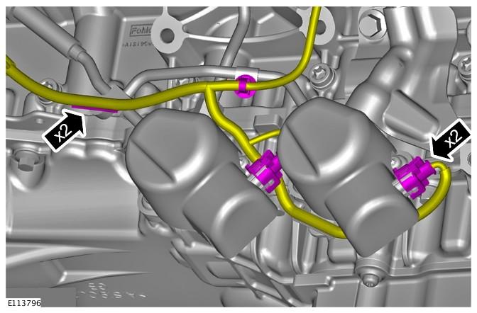
1 Published: 20-Nov-2013 Fuel Charging and Controls - V8 5.0L Petrol - Fuel Rail RH Removal and Installation Special Tool(s) Remover, Fuel Injector Installer, Teflon Seal Re-shape Tool, Teflon Seal Fuel Rail Installation Guide Pins - Threaded Fuel Rail Installation Guide Pins - Unthreaded Removal NOTES: CAUTION: Make sure that tools and equipment are clean, free of foreign material and lubricant. Removal steps in this procedure may contain installation details. Some variation in the illustrations may occur, but the essential information is always correct.
2 1. Refer to: Petrol and Petrol-Ethanol Fuel Systems Health and Safety Precautions ( General Information, Description and Operation). 2. Refer to: Fuel System Pressure Release - V6 3.0L Petrol/V8 5.0L Petrol/V8 S/C 5.0L Petrol ( Fuel System - General Information, General Procedures). 3. Refer to: Battery Disconnect and Connect ( Battery, Mounting and Cables, General Procedures). 4. Refer to: Engine Cover - V8 5.0L Petrol/V8 S/C 5.0L Petrol ( Interior Trim and Ornamentation, Removal and Installation). 5. Refer to: Secondary Bulkhead Panel RH ( Front End Body Panels, Removal and Installation). 6. Refer to: Air Cleaner RH (303-12B Intake Air Distribution and Filtering - V8 5.0L Petrol/V8 S/C 5.0L Petrol, Removal and Installation) CAUTIONS: Be prepared to collect escaping fluids.

3 Make sure that all openings are sealed. Use new blanking caps CAUTIONS: Be prepared to collect escaping fluids. Make sure that all openings are sealed. Use new blanking caps. 12. NOTE: LH shown RH similar.

4 13. Refer to: Fuel Injection Component Cleaning (303-04C Fuel Charging and Controls - V8 5.0L Petrol, General Procedures). 14. NOTE: LH shown RH similar CAUTION: Make a note of the fuel injector alignment to the fuel rail prior to removal. NOTE: LH shown RH similar.
. 18. CAUTIONS: Make sure that the special tool is located correctly to the fuel injector prior to removing the fuel injector.")
: 310-197 19. CAUTIONS: If new fuel injectors are installed, a new injector clamp must be installed.")
5 17. installed. NOTE: This step is only required if a new fuel rail is Refer to: Fuel Rail Pressure (FRP) Sensor (303-14C Electronic Engine Controls - V8 5.0L Petrol, Removal and Installation). 18. CAUTIONS: Make sure that the special tool is located correctly to the fuel injector prior to removing the fuel injector. Make sure that the special tool is held square to the fuel injector during removal. Make sure that all open ports are covered to prevent any foreign material ingress. Special Tool(s): CAUTIONS: If new fuel injectors are installed, a new injector clamp must be installed. If the fuel injector is being removed without a new component being installed, the fuel injector clamp must remain with the fuel injector it is removed with.
6 20. CAUTIONS: Do not use a knife to remove the Teflon seal as damage could occur to the fuel injector. Do not cut the Teflon seal to deep as damage could occur to the fuel injector. Pinch the Teflon seal to allow the tool to cut the Teflon seal without damaging the fuel injector. 21. CAUTION: Do not use any sharp tools to remove the O-ring seal as damage could occur to the fuel injector. 22. WARNING: Do not work on or under a vehicle supported only by a jack. Always support the vehicle on safety stands. Raise and support the vehicle. 23. Refer to: Air Deflector ( Front End Body Panels, Removal and Installation). 24. Refer to: Generator - V8 5.0L Petrol (414-02B Generator and Regulator - V8 5.0L Petrol/V8 S/C 5.0L Petrol, Removal and Installation). 25.
7 27. NOTE: Engine shown removed for clarity.
8 CAUTION: Use a wooden block to protect the oil pan when supporting the engine. Using a suitable hydraulic jack, support the engine. 30.

9 31. WARNING: Do not smoke or carry lighted tobacco or open flame of any type when working on or near any fuel related components. Highly flammable vapors are always present and may ignite. Failure to follow these instructions may result in personal injury. CAUTIONS: lines. Remove and discard the high-pressure fuel supply Be prepared to collect escaping fluids. Make sure that all openings are sealed. Use new blanking caps. NOTE: Engine shown removed for clarity. Installation 1. CAUTION: Lubricate only the union threads with clean engine oil. NOTES: Engine shown removed for clarity. Install the bolts and unions finger tight before final tightening.
10 Remove and discard the blanking caps. 2. Torque: 48 Nm 3. Remove the special tool.

 21 Nm M6 (2) 11 Nm M8 (3)")
11 4. Torque: 48 Nm 5. clarity. NOTE: Some components shown removed for Torque: Unions (1) 21 Nm M6 (2) 11 Nm M8 (3) 25 Nm

12 6. Install new O-ring seals. 7. Install new Teflon seals. Special Tool(s):


13 8. Special Tool(s): CAUTION: If the original fuel injector is being installed, the original fuel injector clamp must installed with the fuel injector it was removed with.
: 310-200-01, 310-200-02 11.")
, make sure that the Teflon seal is clean and free of foreign material and lubricant. 12. installed.")

14 10. CAUTION: If a new cylinder head has been installed then the special tool without the thread must be used to install the fuel rail. Special Tool(s): , CAUTIONS: Make sure that the area around the open fuel injector ports are clean and free of foreign material and lubricant prior to installing the fuel injector. When Installing the fuel injector(s), make sure that the Teflon seal is clean and free of foreign material and lubricant. 12. installed. NOTE: This step is only required if a new fuel rail is Refer to: Fuel Rail Pressure (FRP) Sensor (303-14C Electronic Engine Controls - V8 5.0L Petrol, Removal and Installation). 13. CAUTIONS: If new fuel injectors are installed, a new injector clamp must be installed Make sure that the fuel injector is aligned and installed into the fuel rail correctly, as noted in the removal step. Tighten the fuel rail retaining bolts a turn at a time until the correct torque is achieved. NOTE: Lubricate the fuel injector O-ring seals with clean engine oil. Torque: 20 Nm 14. NOTE: LH shown RH similar. Special Tool(s): ,


15 15. NOTE: LH shown RH similar. Torque: 20 Nm 16. NOTES: LH shown RH similar. Tighten in the sequence indicated. Torque: Bolt 2 30 Nm Bolt 3 30 Nm Bolt 1 30 Nm Bolt 4 30 Nm 17.

16 18. NOTE: LH shown RH similar. Torque: 7 Nm 19. NOTE: LH shown RH similar. 20. NOTE: Remove and discard the blanking caps. Torque: Unions 21 Nm Nut 6 Nm


17 21. WARNING: Do not work on or under a vehicle supported only by a jack. Always support the vehicle on safety stands. Raise and support the vehicle. 22. clarity. NOTE: Some components shown removed for Torque: 21 Nm 23. NOTE: Engine shown removed for clarity. Torque: M10 29 Nm M6 11 Nm

18 25. Torque: 25 Nm
. 28. Lower the vehicle. 29. 30. NOTES: Lubricate the union threads with clean engine oil. Do not tighten at this stage.")
19 26. Refer to: Generator - V8 5.0L Petrol (414-02B Generator and Regulator - V8 5.0L Petrol/V8 S/C 5.0L Petrol, Removal and Installation). 27. Refer to: Air Deflector ( Front End Body Panels, Removal and Installation). 28. Lower the vehicle NOTES: Lubricate the union threads with clean engine oil. Do not tighten at this stage. Remove and discard the blanking caps. 31. Torque: Unions 21 Nm
20 Bolts 8 Nm 32. Torque: 21 Nm
. 38. Refer to: Engine Cover - V8 5.0L Petrol/V8 S/C 5.")
21 Refer to: Air Cleaner RH (303-12B Intake Air Distribution and Filtering - V8 5.0L Petrol/V8 S/C 5.0L Petrol, Removal and Installation). 37. Refer to: Secondary Bulkhead Panel RH ( Front End Body Panels, Removal and Installation). 38. Refer to: Engine Cover - V8 5.0L Petrol/V8 S/C 5.0L Petrol ( Interior Trim and Ornamentation, Removal and Installation). 39. Refer to: Battery Disconnect and Connect ( Battery, Mounting and Cables, General Procedures). Published: 11-May-2011 Front End Body Panels - Air Deflector Removal and Installation Removal NOTE: Removal steps in this procedure may contain installation details. 1. stands. WARNING: Make sure to support the vehicle with axle Raise and support the vehicle. 2. NOTE: Note the fitted position of the washers.
 Sensor Removal and Installation Removal NOTE: Removal steps in this procedure may contain installation details. 1.")
22 Torque: 7 Nm Installation 1. To install, reverse the removal procedure. Published: 11-May-2011 Electronic Engine Controls - V8 5.0L Petrol - Fuel Rail Pressure (FRP) Sensor Removal and Installation Removal NOTE: Removal steps in this procedure may contain installation details. 1. Refer to: Petrol and Petrol-Ethanol Fuel Systems Health and Safety Precautions ( General Information, Description and Operation). 2. Refer to: Fuel System Pressure Release - V6 3.0L Petrol/V8 5.0L Petrol/V8 S/C 5.0L Petrol ( Fuel System - General Information, General Procedures). 3. Refer to: Battery Disconnect and Connect ( Battery, Mounting and Cables, General Procedures). 4. Refer to: Secondary Bulkhead Panel RH ( Front End Body Panels, Removal and Installation). 5. NOTE: Some variation in the illustrations may occur, but the essential information is always correct.


23 6. CAUTIONS: Before disconnecting or removing components, ensure the area around the joint faces and connections are clean. Plug open connections to prevent contamination. Be prepared to collect escaping fluids. Torque: 32 Nm Installation 1. To install, reverse the removal procedure. Published: 06-Jun-2013 Front End Body Panels - Secondary Bulkhead Panel RH Removal and Installation Removal WARNINGS: To avoid accidental deployment, the restraints control module backup power supply must be depleted. Wait at least one minute after disconnecting the battery ground cable(s) before commencing any repair or adjustment to the supplemental restraint system (SRS), or any component(s) adjacent to the SRS sensors. Failure to follow these instructions may result in personal injury. Always wear safety glasses when working on an air bag equipped vehicle and when handling an air bag module. Failure to follow this instruction may result in personal injury. To minimize the possibility of premature deployment, do not use radio key code savers when working on the supplemental restraint system. Failure to follow this instruction may result in personal injury. To minimize the possibility of injury in the event of premature deployment, always carry a live air bag module with the bag and trim cover pointed away from the body. Failure to follow this instruction may result in personal injury.


24 To minimize the possibility of premature deployment, live air bag modules must only be placed on work benches which have been ground bonded and with the trim cover facing up. Failure to follow these instructions may result in personal injury. Never probe the electrical connectors of air bag modules or any other supplemental restraint system component. Failure to follow this instruction may result in personal injury. Painting over the driver air bag module trim cover or instrument panel could lead to deterioration of the trim cover and air bags. Do not for any reason attempt to paint discolored or damaged air bag module trim covers or instrument panel. Install a new component. Failure to follow this instruction may result in personal injury. NOTE: Removal steps in this procedure may contain installation details. All vehicles 1. Disconnect the battery ground cable. Refer to: Battery Disconnect and Connect ( Battery, Mounting and Cables, General Procedures). 2. Refer to: Secondary Bulkhead Panel LH ( Front End Body Panels, Removal and Installation). Vehicles with 3.0L diesel engine 3. Vehicles with 5.0L engine 4.


25 5. Torque: 12 Nm All vehicles 6. Torque: 55 Nm 7.


26 Left-hand drive vehicles 8. Torque: 8 Nm 9. Torque: 7 Nm


27 10. Torque: 8 Nm All vehicles 11. Torque: 7 Nm 12.


28 13. NOTE: Do not disassemble further if the component is removed for access only. Installation 1. located. CAUTION: Make sure that the clip is correctly To install, reverse the removal procedure. Published: 17-Feb-2012 Battery, Mounting and Cables - Battery Disconnect and Connect General Procedures Disconnect 1. Refer to: Battery and Battery Charging Health and Safety Precautions ( General Information, Description and Operation). 2. Obtain and record the audio unit preset radio frequencies. 3. Raise and secure the luggage compartment floor covering.
29 4. CAUTION: Take extra care not to damage the wiring harness. 5. Connect 1. Torque: 6 Nm 2. 3.
30 NOTE: Make sure that both the positive and negative battery terminals are correctly located. 4. Lower the luggage compartment floor covering. 5. NOTE: This step is only necessary when installing a new component. Using the Jaguar approved diagnostic equipment, reset the battery monitoring system. 6. Refer to: Door Window Motor Initialization ( Glass, Frames and Mechanisms, General Procedures). 7. Enter the audio unit preset radio frequencies. 8. Reset the clock to the correct time. 9. Start the engine and allow to idle until the engine reaches normal operating temperature. 10. Switch the engine off. Published: 01-Aug-2012 Fuel System - General Information - Fuel System Pressure Release V6 3.0L Petrol/V8 5.0L Petrol/V8 S/C 5.0L Petrol General Procedures Draining 1. Remove the fuel pump fuse. 2. Remove the fuel filler cap. 3. CAUTION: When depressurising the fuel system, make sure that there is no throttle input. Failure to follow this instruction may cause damage to the vehicle.
31 Start the engine and allow it to idle until the engine stalls. 4. Crank the engine for approximately five seconds to make sure that the fuel rail pressure is released. Filling 1. NOTE: Make sure all repairs have been carried out before proceeding to the following steps. Install the fuel pump fuse. 2. Install the fuel filler cap. 3. Read and clear stored DTC fault codes. Published: 16-Mar-2016 Fuel Charging and Controls - V8 5.0L Petrol - Fuel Injection Component Cleaning General Procedures General Equipment Pneumatic vacuum gun WARNINGS: Cleaning Do not carry out any repairs to the fuel system with the engine running. Failure to follow this instruction may result in personal injury. Do not smoke or carry lighted tobacco or open flame of any type when working on or near any fuel related components. Highly flammable vapors are always present and may ignite. Failure to follow these instructions may result in personal injury. If fuel contacts the eyes, flush the eyes with cold water or eyewash solution and seek immediate medical attention. Place the vehicle in a well ventilated, quarantined area and arrange ' No Smoking/Petrol Fumes' signs about the vehicle. Wash hands thoroughly after fuel handling, as prolonged contact may cause irritation. Should irritation develop, seek medical attention. Do not carry or operate cellular phones when working on or near any fuel related components. Highly flammable vapors are always present and may ignite. Failure to follow these instructions may result in personal injury. CAUTIONS: Before using the cleaning fluid, protect all electrical components and connectors with lint-free non-flocking material. Make sure that all parts removed from the vehicle are placed on the lint-free non-flocking material. Make sure that any protective clothing worn is clean and made from lint-free non-flocking material. Make sure that clean non-plated tools are used. Clean tools using a new brush that will not lose its bristles, prior to starting work on the vehicle. Use a steel topped workbench and cover it with clean, lint-free non-flocking material.
32 Make sure the workshop area in which the vehicle is being worked on is as clean and as dust free as possible. Foreign matter from work on clutches, brakes or from machining or welding operations can contaminate the fuel system and may result in later malfunction. 1. Using a new brush that will not lose its bristles, brush the components being removed and the surrounding area. 2. Using a pneumatic vacuum gun, remove all traces of foreign material. General Equipment: Pneumatic vacuum gun Published: 11-May-2011 General Information - Petrol and Petrol-Ethanol Fuel Systems Health and Safety Precautions Description and Operation WARNINGS: Fuel may not give adequate warning before toxic or harmful effects arise. Exposure to fuel can be harmful and can cause severe health damage or death. Extreme care must be exercised when handling hot fluids. Always wash off spilled fluids from affected areas of skin immediately. Highly flammable mixtures are always present and may ignite when working on fuel systems. Do not allow naked flames, sparks or lighted substances to come near fuel related components. Fuel must not be used as a cleaning agent. Keep fuel containers tightly closed, out of direct sunlight and in a cool area. Keep away from heat sources, ignition sources and oxidizing agents. SKIN CONTACT: Excessive or prolonged skin contact with diesel fuel may cause serious skin disorders including skin cancer. SKIN CONTACT: Fuel is mildly irritating to the skin and may cause dermatitis due to defatting effect. Remove contaminated clothing. Wash affected areas of skin with soap and water. Seek medical attention for any persistent skin irritation or abnormality. Wash contaminated clothing before reuse. EYE CONTACT: Fuel is mildly irritating to the eyes. Flush with plenty of running water, blinking as often as possible. Do not force the eyelid open. Seek medical attention for any persistent eye irritation or abnormality. SWALLOWED: Fuel is moderately toxic and tends to foam on vomiting. If drawn into the lungs, inflammation may develop. Do not induce vomiting. If spontaneous vomiting occurs place the victim in a forward position to reduce the risk of fuel being drawn into the lungs. Give nothing by mouth. If breathing but unconscious, place in the recovery position. If breathing has stopped, apply artificial respiration. Seek immediate medical attention. INHALED: Fuel is toxic to the respiratory and other body systems. Exposure may result in various symptoms including drowsiness, unconsciousness or severe health damage. Move a victim to fresh air. Keep a victim warm and at rest. If unconscious, place in the recovery position. If not breathing, apply artificial respiration. Give cardiac massage if necessary. Seek immediate medical attention. CAUTIONS: Fuel injection equipment is manufactured to very precise tolerances and fine clearances. It is essential that absolute cleanliness is observed when working with these components.

33 Make sure that the workshop area in which the vehicle is being worked on is as clean and as dust free as possible. Published: 14-Jun-2012 Interior Trim and Ornamentation - Engine Cover V8 5.0L Petrol/V8 S/C 5.0L Petrol Removal and Installation Removal 1. NOTE: Some variation in the illustrations may occur, but the essential information is always correct. Remove the engine cover. Installation 1. To install, reverse the removal procedure. Published: 11-May-2011 Generator and Regulator - V8 5.0L Petrol/V8 S/C 5.0L Petrol - Generator V8 5.0L Petrol Removal and Installation Removal NOTE: Removal steps in this procedure may contain installation details. 1. Refer to: Battery Disconnect and Connect ( Battery, Mounting and Cables, General Procedures). 2. stands. WARNING: Make sure to support the vehicle with axle

. 4. 5. Torque: 25 Nm 6.")

34 Raise and support the vehicle. 3. Refer to: Air Deflector ( Front End Body Panels, Removal and Installation) Torque: 25 Nm 6. Torque: 12 Nm 7. NOTE: Tighten the bolts in the indicated sequence. Torque: 48 Nm


35 Installation 1. To install, reverse the removal procedure. Published: 17-Nov-2015 Intake Air Distribution and Filtering - V8 5.0L Petrol/V8 S/C 5.0L Petrol - Air Cleaner RH Removal and Installation Removal NOTES: Removal steps in this procedure may contain installation details. Some variation in the illustrations may occur, but the essential information is always correct


36 3. 4. Torque: 8 Nm 5. Do not disassemble further if the component is removed for access only. 6. NOTE: LH illustration shown, RH is similar.


37 7. NOTE: LH illustration shown, RH is similar. 8. NOTE: LH illustration shown, RH is similar. Installation 1. To install, reverse the removal procedure.
HIGH PRESSURE FUEL PUMP 1
 2010 X250, 303-04 FUEL CHARGING AND CONTROLS - V8 5.0L PETROL HIGH PRESSURE FUEL PUMP 1 (G1185928) REMOVAL AND INSTALLATION 19.45.30 HIGH PRESSURE FUEL PUMP FRONT RENEW 5000 CC, AJ V8, NATURALLY ASPIRATED
Fuel Injector ( )
") Published: Mar 29, 2010 Fuel Injector (196010) Special Service Tools Fuel Injector remover 303-1127 Removal WARNING: Do not smoke or carry lighted tobacco or open flame of any type when working on or near
Published: Mar 29, 2010 Fuel Injector (196010) Special Service Tools Fuel Injector remover 303-1127 Removal WARNING: Do not smoke or carry lighted tobacco or open flame of any type when working on or near
 Page 1 of 32 09-Mar-2014 Fuel Charging and Controls - V8 5.0L Petrol - High Pressure Fuel Pump 1 Removal and Installation Removal CAUTION: Always carry out the cleaning process before carrying out any
Fuel Pump Module. Fuel Pump Module. Special Service tools. Remover/Installer, Fuel Pump Module/Fuel Transfer Pump Locking Ring A 1.
 Fuel Pump Module Fuel Pump Module Special Service tools Remover/Installer, Fuel Pump Module/Fuel Transfer Pump Locking Ring 310-072A 1. WARNING: PLACE THE VEHICLE IN A QUARANTINED AREA AND ARRANGE NO SMOKING/PETROL
LINCOLN. Continental 1
 3154_U01.qxd 8/1/03 7:28 AM Page 1 Continental 1 BRAKES...1-27 DRIVE TRAIN...1-21 ENGINE REPAIR...1-7 FUEL SYSTEM...1-20 PRECAUTIONS...1-7 SPECIFICATION CHARTS...1-2 STEERING AND SUSPENSION...1-22 A Air
FUEL TANK DRAINING. Special Tool(s) Special Tool(s)
 Special Tool(s)") FUEL TANK DRAINING Special Tool(s) Zoom Special Tool(s) WARNING: Do not smoke, carry lighted tobacco or open flame of any type when working on or near any fuel-related component. Highly flammable mixtures
FUEL TANK DRAINING Special Tool(s) Zoom Special Tool(s) WARNING: Do not smoke, carry lighted tobacco or open flame of any type when working on or near any fuel-related component. Highly flammable mixtures
M-9407-GT05 Mustang GT Dual Fuel Pump Kit INSTRUCTION SHEET
 Please contact the Techline for the most current instruction information (800) FORD788!!! PLEASE READ THE FOLLOWING INSTRUCTIONS CAREFULLY PRIOR TO INSTALLATION!!! OVERVIEW: The following information describes
INTAKE MANIFOLD (G )
") PUBLISHED: 13-FEB-2018 2011.0 RANGE ROVER SPORT (LS), 303-01 ENGINE - V8 N/A 5.0L PETROL INTAKE MANIFOLD (G1245958) REMOVAL AND INSTALLATION 30.15.02 MANIFOLD - INTAKE - LH /FRONT /EACH - RENEW 5000 CC,
PUBLISHED: 13-FEB-2018 2011.0 RANGE ROVER SPORT (LS), 303-01 ENGINE - V8 N/A 5.0L PETROL INTAKE MANIFOLD (G1245958) REMOVAL AND INSTALLATION 30.15.02 MANIFOLD - INTAKE - LH /FRONT /EACH - RENEW 5000 CC,
MY F150 CrewCab 1. Tools Required 10X. Page 1 of 15 DL3J-19A014-AA Copyright Ford 2013 FoMoCo
 2013-2014MY F150 CrewCab 1 Tools Required A B C D E F G 4X H I J K 3X L 3X 2X 10X 2X Page 1 of 15 DL3J-19A014-AA Copyright Ford 2013 FoMoCo 2013-2014MY F150 CrewCab 2 Vehicles with selector lever in floor
M-9424-M50B 2012 Boss 302 Intake Manifold INSTALLATION INSTRUCTIONS
 !!! PLEASE READ ALL OF THE FOLLOWING INSTRUCTIONS CAREFULLY PRIOR TO INSTALLATION. WARNING: CUSTOM CALIBRATION REQUIRED! CALIBRATION NOT INCLUDED! KIT CONTENTS: 1) Intake Manifold Assembly 2) Assembly
06/03. Fuel Vapor Odor In Interior Convertible Models Only Repair Procedure. Note: Ensure WDS is loaded with software release JTP 759/24 or later.
 SERVICE XK DATE 06/03 TECHNICAL BULLETIN Fuel Vapor Odor In Interior Convertible Models Only Repair Procedure 303-61 MODEL 1999-2003 MY XK Convertible VIN 031303-A35945 Issue: Owners of some 1999-2003
Model: OBD-L On-Board-Diagnostics II Memory Saver Detector
 Model: OBD-L On-Board-Diagnostics II Memory Saver Detector OWNERS MANUAL IMPORTANT SAFETY INSTRUCTIONS SAVE THESE INSTRUCTIONS This manual will show you how to use your memory saver detector safely and
SDS. Safety Data Sheet TCP 950E PRODUCT AND COMPANY IDENTIFICATION HAZARDS IDENTIFICATION
 Page 1 of 6 1 PRODUCT AND COMPANY IDENTIFICATION Product Name: Revision Date: Number: CAS Number: Product Code: Synonyms: Company_ Identification Tri-County Petroleum State Route 1036 Defiance, PA 16672
JOHN DEERE WORLDWIDE COMMERCIAL & CONSUMER EQUIPMENT DIVISION. Lawn Tractors L100, L110, L120, and L130 TM2026 DECEMBER 2002 TECHNICAL MANUAL
 2026 December 2002 JOHN DEERE WORLDWIDE COMMERCIAL & CONSUMER EQUIPMENT DIVISION Lawn Tractors L100, L110, L120, and L130 TM2026 DECEMBER 2002 TECHNICAL MANUAL North American Version Litho in U.S.A. Safety
REMOVAL AND INSTALLATION
 310-00-1 Fuel System 310-00-1 REMOVAL AND INSTALLATION Fuel Tank and Filler Pipe Special Tool(s) Fuel Tank Drain Hose 310-F013 2. NOTE: Steps 2 through 5 are only necessary if servicing the fuel tank or
Light condition and operation Windshield glass condition Wiper blade condition Paint condition and corrosion Fluid leaks Door and hood lock condition
 GENERAL CHECKS Engine Compartment The following should be checked regularly: Engine oil level and condition Transmission fluid level and condition Brake fluid level Clutch fluid level Engine coolant level
Vehicle battery BATTERY WARNING SYMBOLS BATTERY CARE
 Vehicle battery BATTERY WARNING SYMBOLS On the battery label, the warning signs are as follows: BATTERY CARE No smoking, no naked flames, no sparks. The battery may emit explosive gas. Keep away from children
Fuel Charging and Controls
 Page 1 of 9 SECTION 303-04C: Fuel Charging and Controls 6.7L Diesel 2011 F-250, 350, 450, 550 Super Duty Workshop Manual DESCRIPTION AND OPERATION Procedure revision date: 03/12/2010 Fuel Charging and
2002 Escape Workshop Manual
 Page 1 of 6 SECTION 501-10: Seating 2002 Escape Workshop Manual REMOVAL AND INSTALLATION Procedure revision date: 01/07/2002 Seat Track Driver Seat Removal WARNING: Always wear safety glasses when repairing
2005 Freestyle/Five Hundred/Montego Workshop Manual
 Page 1 of 8 SECTION 501-10: Seating 2005 Freestyle/Five Hundred/Montego Workshop Manual DISASSEMBLY AND ASSEMBLY Procedure revision date: 07/14/2006 Seat Backrest Front Printable View (466 KB) Special
SUPPLEMENTAL RESTRAINT SYSTEM (SRS)
") 52B-1 GROUP 52B SUPPLEMENTAL RESTRAINT SYSTEM (SRS) CONTENTS GENERAL DESCRIPTION......... 52B-3 SERVICE PRECAUTIONS......... 52B-15 SRS AIR BAG DIAGNOSIS........ 52B-17 INTRODUCTION.....................
52B-1 GROUP 52B SUPPLEMENTAL RESTRAINT SYSTEM (SRS) CONTENTS GENERAL DESCRIPTION......... 52B-3 SERVICE PRECAUTIONS......... 52B-15 SRS AIR BAG DIAGNOSIS........ 52B-17 INTRODUCTION.....................
30,000mWh LITHIUM-POLYMER CAR JUMP STARTER USER S MANUAL PLEASE READ THIS MANUAL CAREFULLY BEFORE OPERATION
 Lithium Battery Disposal: This product contains a lithium battery. A lithium battery should not be thrown away in the trash. Please dispose of the battery at an authorized disposal or recycle center. Check
All vehicles. 1. Turn all vehicle accessories OFF. system (SRS) vehicle and when handling an air bag module. This will reduce the risk of injury in
 vehicle and when handling an air bag module. This will reduce the risk of injury in") 501-20B-1 GENERAL PROCEDURES (SRS) Deactivation and Reactivation Special Tool(s) Diagnostic Tool, Restraint System 418-F403 Diagnostic Tool, Restraint System (2 required) 418-133 501-20B-1 WARNING: Never
501-20B-1 GENERAL PROCEDURES (SRS) Deactivation and Reactivation Special Tool(s) Diagnostic Tool, Restraint System 418-F403 Diagnostic Tool, Restraint System (2 required) 418-133 501-20B-1 WARNING: Never
SVE BULLETIN. QVM Bulletin: Q-123R3 Date: 18 August, 2010 Aftermarket Plasma Cutting/ Welding Operations on F Trucks
 Q-3R3 SVE BULLETIN SPECIAL VEHICLE ENGINEERING BODY BUILDERS ADVISORY SERVICE E-Mail via website: wwwfleetfordcom/truckbbas (click "Contact Us") Toll-free: (877) 840-4338 QVM Bulletin: Q-3R3 Date: 8 August,
 Page 1 of 14 Oil Pan Removal & Installation 4.2L Engine 4WD Vehicles To Remove: 1. Before servicing the vehicle refer to the precautions at the beginning of this section. 2. Raise and support the vehicle.
Fuel supply system components, removing and installing
 20-1 Fuel supply system components, removing and installing Checking fuel system for leaks Removing and installing fuel filter and draining water, engine code AAZ: Repair Manual, 1.9 Liter 4-Cyl. 2V Eco-Diesel
GROUP 52B CONTENTS. Battery posts, terminals and related accessories contain lead and lead compounds. WASH HANDS AFTER HANDLING.
 52B-1 GROUP 52B CONTENTS GENERAL DESCRIPTION......... 52B-3 SERVICE PRECAUTIONS......... 52B-17........ 52B-20 INTRODUCTION..................... 52B-20 TROUBLESHOOTING STRATEGY...... 52B-20 TROUBLE CODE
M-2300-M Mustang GT Rear Disc Brake Bracket Kit INSTALLATION INSTRUCTIONS
 Please contact the Tech Line for the most current instruction information (800) 367-3788!!! PLEASE READ THE FOLLOWING INSTRUCTIONS CAREFULLY PRIOR TO INSTALLATION!!! INTRODUCTION: This kit allows for the
2014 Ford Edge SE ENGINE Fuel Tank & Lines - Edge, MKX
 17. Remove the 2 nuts, 7 bundle retainer clips and remove the fuel supply and EVAP vapor tube assembly. To install, tighten to 9 Nm (80 lb-in). 18. To install, reverse the removal procedure. FUEL LINES
NiCd Product Safety Data Sheet
 MSDS3589 NiCd Product Safety Data Sheet PRODUCT NAME: Moltech Power Systems Rechargeable Battery TRADE NAME: Nickel Cadmium Battery CHEMICAL SYSTEM: Nickel Cadmium Type No.: Volts: Approximate Weight:
NiCd Material Safety Data Sheet
 Product Name: Nickel Cadmium Battery Chemical Systems: Nickel Cadmium Designed for Recharge: Yes NiCd Material Safety Data Sheet According to REACH regulation (EC1907/2006, Article 31) these batteries
Material Safety Data Sheet for Lithium Button Cell Series
 SECTION I Hazardous Ingredients / Identity Information IMPORTANT: Use under normal conditions, the lithium battery is hermetically sealed. Ingestion: Swallowing may lead to serious injury or death in as
Airless Spray Gun INSTRUCTIONS DP psi (345 bar) Maximum Working Pressure
 Maximum Working Pressure") INSTRUCTIONS DP-6376 Airless Spray Gun 5000 psi (345 bar) Maximum Working Pressure INSTRUCTIONS This manual contains important warnings and information. READ AND KEEP FOR REFERENCE. Table of Contents Warnings......................................
INSTRUCTIONS DP-6376 Airless Spray Gun 5000 psi (345 bar) Maximum Working Pressure INSTRUCTIONS This manual contains important warnings and information. READ AND KEEP FOR REFERENCE. Table of Contents Warnings......................................
OPERATOR S MANUAL JUMP STARTER. and DC Power Source. Model No CAUTION: Sears, Roebuck and Co., Hoffman Estates, IL U.S.A.
 OPERATOR S MANUAL JUMP STARTER and DC Power Source Model No. 71489 CAUTION: Read and follow all Safety Rules and Operating Instructions before Every Use of this Product. SAVE THESE INSTRUCTIONS. Sears,
AIR CLEANER GENERAL REMOVAL. 1CAUTION Do not run engine without filter element in place. Debris could be drawn into the engine causing damage.
 AIR CLEANER GENERAL The air cleaner prevents foreign material from entering the carburetor and engine by trapping airborne dust and dirt in the filter element. Service air cleaner filter element every
FUEL SYSTEM PRECAUTION FU 1
 2GR-FE EL EL SYSTEM EL SYSTEM PRECAUTION 1 1. EXPRESSIONS OF IGNITION SWITCH (a) The type of the ignition switch used on this model differs according to the specifications of the vehicle. The expressions
ENGINE LUBRICATION 12-1 CONTENTS GENERAL INFORMATION... 2 LUBRICANTS... 3 SPECIAL TOOLS... 3 ENGINE OIL COOLER ON-VEHICLE SERVICE...
 12-1 ENGINE LUBRICATION CONTENTS 12109000129 GENERAL INFORMATION... 2 LUBRICANTS... 3 SPECIAL TOOLS... 3 ON-VEHICLE SERVICE... 3 Engine Oil Check... 3 Engine Oil Replacement... 3 Oil Filter Replacement...
1995 Mercury Grand Marquis GS
 AIR BAG SYSTEM CAUTION: Read the following safety precautions BEFORE servicing steering columns on vehicles equipped with air bag restraint system. ALWAYS wear safety glasses when servicing vehicle with
Page 1 of 6. MSDS for # PATINA FINISHES
 Page 1 of 6 ÚÄÄÄÄÄÄÄÄÄÄÄÄÄÄÄÄÄÄÄÄÄÄÄÄÄÄÄÄÄÄÄÄÄÄÄÄÄÄÄÄÄÄÄÄÄÄÄÄÄÄÄÄÄÄÄ ³ M A T E R I A L S A F E T Y D A T A S H E E T ³ ÀÄÄÄÄÄÄÄÄÄÄÄÄÄÄÄÄÄÄÄÄÄÄÄÄÄÄÄÄÄÄÄÄÄÄÄÄÄÄÄÄÄÄÄÄÄÄÄÄÄÄÄÄÄÄÄÙ ³ SECTION 1 - CHEMICAL PRODUCT
PSJ-2212, PSJ-3612, PSJ-4424
 Model: PSJ-2212, PSJ-3612, PSJ-4424 Jump Starter and DC Power Source OWNER S MANUAL PSJ-2212 PLEASE SAVE THIS OWNER S MANUAL AND READ BEFORE EACH USE. This manual will explain how to use your jump starter
INTAKE AIR TEMPERATURE SENSOR (IAT)
") INTAKE AIR TEMPERATURE SENSOR (IAT) 4.8 Refer to the ELECTRICAL DIAGNOSTIC MANUAL for information on the function and testing of the intake air temperature sensor (IAT sensor). sm054 To prevent accidental
INTAKE AIR TEMPERATURE SENSOR (IAT) 4.8 Refer to the ELECTRICAL DIAGNOSTIC MANUAL for information on the function and testing of the intake air temperature sensor (IAT sensor). sm054 To prevent accidental
SECTION 7 1 DO IT YOURSELF MAINTENANCE MR2 U. Introduction
 SECTION 7 1 DO IT YOURSELF MAINTENANCE Introduction Engine compartment overview............................... 160 Trunk room overview........................................ 161 Fuse locations.............................................
Document No.:JJJ/JS-QW Date: 06/13/12 Product Name: Nickel Cadmium Battery Chemical Systems: Nickel-Cadmium Designed for Recharge: Yes
 NiCd Material Safety Data Sheet Document No.:JJJ/JS-QW751-06 Date: 06/13/12 Product Name: Nickel Cadmium Battery Chemical Systems: Nickel-Cadmium Designed for Recharge: Yes SECTION I-MANUFACTURER INFORMATION.
IMPORTANT INFORMATION
 Table of Contents IMPORTANT INFORMATION Section 1B - Maintenance MAINTENANCE 1 B Specifications........................... 1B-1 Special Tools........................... 1B-2 Mercury/Quicksilver Lubricants
FOR ALL OF VEHICLES PRECAUTION
 IN10 PRECAUTION IN0FA01 1. FOR VEHICLES EQUIPPED WITH SRS AIRBAG AND SEAT BELT PRETENSIONER (a) The CELICA is equipped with an SRS (Supplemental Restraint System), such as the driver airbag, front passenger
PRODUCT NAME: NI-MH SEALED CELL BATTERY
 PRODUCT NAME: NI-MH SEALED CELL BATTERY P.C.: 518119 Yan An Road, Kuichong, Longgang, Shenzhen, China +86 755 84203333 Fax Number for Information +86 755 84202222!" # "! $ %&" $ '&#% & $%& (&$ ) # ) )
Disc Brake System ( For Cross-Country)
") Technical Service Instructions General Safety Information Disc Brake System ( For Cross-Country) SI-8C60F t WARNING Please use extra caution to keep your fingers away from the rotating disc brake rotor
Technical Service Instructions General Safety Information Disc Brake System ( For Cross-Country) SI-8C60F t WARNING Please use extra caution to keep your fingers away from the rotating disc brake rotor
FUEL SYSTEM SECTION CONTENTS B ENGINE FL-1
 B ENGINE A SECTION FUEL SYSTEM FL C D CONTENTS E PRECAUTIONS... 2 Precautions for Supplemental Restraint System (SRS) AIR BAG and SEAT BELT PRE-TEN- SIONER... 2 PREPARATION... 3 Special Service Tools...
LDG6000SA DIESEL GENERATOR OWNERS MANUAL
 LDG6000SA DIESEL GENERATOR OWNERS MANUAL BEFORE OPERATING THIS EQUIPMENT PLEASE READ THESE INSTRUCTIONS CAREFULLY Preface Thank-you for purchasing this generator. This operation manual contains information
FOR ALL OF VEHICLES PRECAUTION
 INTRODUCTION PRECAUTION IN9 1. FOR VEHICLES EQUIPPED WITH SRS AIRBAG (a) The 4RUNNER is equipped with an SRS (Supplemental Restraint System), such as the driver airbag, front passenger airbag and seat
LUBRICATION SYSTEM (April, 2003)
") SYSTEM (April, 2003) SYSTEM (April, 2003) ONVEHICLE INSPECTION 1. CHECK ENGINE OIL LEVEL (a) After warming up the engine and then 5 minutes after the engine stops, oil level should be between the L and
SYSTEM (April, 2003) SYSTEM (April, 2003) ONVEHICLE INSPECTION 1. CHECK ENGINE OIL LEVEL (a) After warming up the engine and then 5 minutes after the engine stops, oil level should be between the L and
PRODUCT SAFETY DATA SHEET
 Page 1 of 4 PRODUCT SAFETY DATA SHEET PRODUCT NAME: Energizer Battery Type No.: Volts: 3.0 TRADE NAMES: Approximate Weight: 11 40 g. CHEMICAL SYSTEM: Lithium Manganese Dioxide Designed for Recharge: No
PRECAUTIONS ENGINE REPAIR
 3234_U01.qxd 9/23/03 3:44 PM Page 13 BLAZER XTREME TRAILBLAZER BRAVADA ENVOY JIMMY 1-13 PRECAUTIONS Before servicing any vehicle, please be sure to read all of the following precautions, which deal with
M-9424-M50CJ INTAKE MANIFOLD INSTALLATION INSTRUCTIONS
 Please visit www.fordracingparts.com for the most current instruction information!!! PLEASE READ ALL OF THE FOLLOWING INSTRUCTIONS CAREFULLY PRIOR TO INSTALLATION. AT ANY TIME YOU DO NOT UNDERSTAND THE
Seat Cushion Front. Driver Power Front Seat Cushion. Item Part Number Description Cushion trim cover
 SECTION 501-10: Seating 2009 Mustang Workshop Manual DISASSEMBLY AND ASSEMBLY Procedure revision date: 05/23/2008 Seat Cushion Front Special Tool(s) Vehicle Communication Module (VCM) and Integrated Diagnostic
SPECIFICATIONS Horsepower: 1.5 HP Running Maximum PSI: 125 PSI Tank Capacity: 15 Gallons CFM: 6 40 PSI 5 90 PSI
 15 GALLON AIR COMPRESSOR Model: 7678 DO NOT RETURN TO STORE Please call 800-348-5004 for parts and service CALIFORNIA PROPOSITION 65 WARNING: You can create dust when you cut, sand, drill or grind materials
SECTION B: Supplemental Restraint System 2002 Lincoln LS Workshop Manual REMOVAL AND INSTALLATION Procedure revision date: 02/27/2004
 SECTION 501-20B: Supplemental Restraint System 2002 Lincoln LS Workshop Manual REMOVAL AND INSTALLATION Procedure revision date: 02/27/2004 Clockspring Removal WARNING: Always wear safety glasses when
REMOVAL AND INSTALLATION Procedure revision date: 05/17/2000
 1997 Aerostar/Ranger REMOVAL AND INSTALLATION Procedure revision date: 05/17/2000 Module, Driver Side Air Bag NOTE: In general, if the air bag did not deploy in an accident, it was not needed. Complete
10/20/ Ford E 250 Engine Mechanical > Engine, 4.6L and 5.4L > IN VEHICLE REPAIR > Intake Manifold 5.4L
 2005 Ford E 250 : Engine Mechanical > Engine, 4.6L and 5.4L > IN VEHICLE REPAIR > Intake Manifold 5.4L Intake Manifold 5.4L Listen SECTION 303 01A: Engine 4.6L and 5.4L 2005 E Series Workshop Manual IN
OPERATION MANUAL ESX-2
 OPERATION MANUAL ESX-2 Fuel System Cleaner RTI Technologies, Inc 4075 East Market St. York, PA 17402 800-468-2321 www.rtitech.com Manual P/N 035-80873-00 (Rev A) Table of Contents Component Description...2
SECTION 8 1 DO IT YOURSELF MAINTENANCE. Introduction
 SECTION 8 1 DO IT YOURSELF MAINTENANCE Introduction Engine compartment overview............................... 396 Fuse locations............................................. 397 Do it yourself service
ENGINE SPECIFICATIONS
 ENGINE SPECIFICATIONS MECHANICAL LOCATION INDEX Engine cover 1 (See ENGINE COVER REMOVAL/INSTALLATION.) 2 Drive belt Page 1 (See DRIVE BELT DEFLECTION/TENSION INSPECTION.) (See DRIVE BELT ADJUSTMENT.)
GENERATOR MODEL NO: FG2500 OPERATION & MAINTENANCE INSTRUCTIONS PART NO: LS0114
 GENERATOR MODEL NO: FG2500 PART NO: 8857727 OPERATION & MAINTENANCE INSTRUCTIONS LS0114 INTRODUCTION Thank you for purchasing this CLARKE Generator. Before attempting to use this product, please read this
MULTIVOLTAGE PORTABLE BATTERY CHARGER MVM
 _ M MULTIVOLTAGE PORTABLE BATTERY CHARGER MVM User's MANUAL Code: MVM Version: 01-BF Date: OCT 2005 Page 1/10 _ 1. INTRODUCTION Before starting to use your Energic plus MVM battery charger, please take
Document No. Issue Date Last Amended January Last Amended by
 Product Name: Lithium Battery Pack Type : LB7P For use with: RescueME PLB1 Chemistry: LiMnO 2 Total Weight: 51g Nominal Voltage: 9V Construction: Battery containing three Energizer 123 cells connected
OWNERS MANUAL Models: XP400, XP500, XP750C INSTANT POWER Jump Starter and DC Power Source
 OWNERS MANUAL Models: XP400, XP500, XP750C INSTANT POWER Jump Starter and DC Power Source XP400 XP500 XP750C PLEASE SAVE THIS OWNER S MANUAL AND READ BEFORE EACH USE. This manual will explain how to use
Installation Manual. Truck Edition Single Temperature Systems TS-200 TS-300 TS-500. TK IM (Rev. 4, 05/04)
") Installation Manual Truck Edition Single Temperature Systems TS-200 TS-300 TS-500 TK 50727-1-IM (Rev. 4, 05/04) Copyright 1999 Thermo King Corp., Minneapolis, MN, U.S.A. Truck Edition Installation Manual
Installation Manual Truck Edition Single Temperature Systems TS-200 TS-300 TS-500 TK 50727-1-IM (Rev. 4, 05/04) Copyright 1999 Thermo King Corp., Minneapolis, MN, U.S.A. Truck Edition Installation Manual
Fuel and refuelling SAFETY PRECAUTIONS FUEL QUALITY
 SAFETY PRE Automotive fuels can cause serious injury and even death, if misused. Petroleum gasses are highly flammable, have a low flash point, and are explosive, especially in confined spaces. Avoid exposing
2. NOTE: On vehicles equipped with automatic transmissions, move the shift lever to the 1 position to ease removal.
 Page 1 of 28 Section 501-12: Instrument Panel and Console REMOVAL AND INSTALLATION 1997 F-150, F-250 Workshop Manual Instrument Panel Removal 1. WARNING: TO AVOID ACCIDENTAL DEPLOYMENT AND POSSIBLE INJURY,
Lubricating Oil Pan
 007-025 Lubricating Oil Pan Preparatory Steps Batteries can emit explosive gases. To reduce the possibility of personal injury, always ventilate the compartment before servicing the batteries. To reduce
FUEL PUMP CAMSHAFT TIMING ADJUSTMENT (G )
") PUBLISHED: 10-OCT-2017 2010.0 RANGE ROVER SPORT (LS), 303-01 ENGINE - V8 S/C 5.0L PETROL FUEL PUMP CAMSHAFT TIMING ADJUSTMENT (G1473741) GENERAL PROCEDURES 19.90.17 HIGH PRESSURE FUEL TIMING CHECK AND
PUBLISHED: 10-OCT-2017 2010.0 RANGE ROVER SPORT (LS), 303-01 ENGINE - V8 S/C 5.0L PETROL FUEL PUMP CAMSHAFT TIMING ADJUSTMENT (G1473741) GENERAL PROCEDURES 19.90.17 HIGH PRESSURE FUEL TIMING CHECK AND
REMOVAL AND INSTALLATION
 501-20B-1 REMOVAL AND INSTALLATION 501-20B-1 Occupant Classification Sensor Item Part Number Description 7 61704 Seat track assembly Special Tool(s) 8 Safety belt buckle switch electrical connector (part
Rayco 1620, 1625, 1631 & 1635 Upgrade Wheel Assembly
 Rayco 1620, 1625, 1631 & 1635 Upgrade Wheel Assembly If you have any questions or concerns, please call 1-800-473-3683 BEFORE YOU BEGIN Read these instructions completely and carefully IMPORTANT - Before
Introduction 1 Important Safety Information 3 Installing TopKAT Series 900 Replacement Report Printer Kit 5
 MDE-5061 TopKAT Series 900 Replacement Report Printer Kit (M11810K001) Installation Instructions March 2013 Introduction Purpose This manual provides instructions for installing the TopKAT Series 900 Replacement
 Page 1 of 6 Section 303-01A: Basic Engine 4.2L REMOVAL 1997 F-150/250 Workshop Manual Engine Special Service Tool(s) Engine Lifting Bracket or equivalent 014-00730 Removal 1. Remove the hood. 2. On A/C
Egg Harbor Fire Department and First Responders Standard Operating Guidelines
 Egg Harbor Fire Department and First Responders Standard Operating Guidelines SUBJECT: WINDSHIELD CUTTER OPERATION SOG 326 AND MAINTENANCE (RHYNO TOOL) PURPOSE: The purpose of this S.O.G. is to establish
Safety Belt Retractor and Pretensioner
 SECTION 501-20A: Safety Belt System 2009 Mustang Workshop Manual REMOVAL AND INSTALLATION Procedure revision date: 12/03/2008 Safety Belt Retractor and Pretensioner Safety Belt Retractor and Pretensioner
2003 Explorer/Mountaineer Workshop Manual
 Page 1 of 11 SECTION 414-00: Battery and Charging System 2003 Explorer/Mountaineer Workshop Manual DIAGNOSIS AND TESTING Procedure revision date: 06/18/2002 Charging System Printable View (257 KB) Refer
PI1500X Power Inverter User s Manual
 PI1500X Power Inverter User s Manual featuring WARNING Failure to follow instructions may cause damage or explosion, always shield eyes. Read entire instruction manual before use. Warning: This product
INSTALLATION INSTRUCTIONS
 INSTALLATION INSTRUCTIONS [1] Description: Tow Hitch Wire Harness Kit [2] Application: Nissan Rogue Note: Tow Harness application is limited to specific vehicle option packages that include tow harness
SRS AIRBAG Toyota RAV4. Supplemental Restraint System - RAV4 PRECAUTION CAUTION:
 2005 RESTRAINTS Supplemental Restraint System - RAV4 SRS AIRBAG PRECAUTION CAUTION: The TOYOTA RAV4 is equipped with SRS that includes a driver airbag, front passenger airbag, side airbag and curtain shield
Model: SE-4020-CA Automatic Battery Charger
 OWNERS MANUAL Model: SE-4020-CA Automatic Battery Charger PLEASE SAVE THIS OWNERS MANUAL AND READ BEFORE EACH USE. This manual will explain how to use the battery charger safely and effectively. Please
2002 Mustang Workshop Manual
 Page 1 of 13 SECTION 303-01B: Engine 4.6L (2V) 2002 Mustang Workshop Manual REMOVAL Procedure revision date: 01/02/2003 Cylinder Heads Special Tool(s) Remover, Crankshaft Vibration Damper 303-009 (T58P-6316-D)
DISASSEMBLY AND ASSEMBLY
 501-10-1 Seating 501-10-1 DISASSEMBLY AND ASSEMBLY Front Seat Cushion Special Tool(s) Worldwide Diagnostic System (WDS) Vehicle Communication Module (VCM) with appropriate adapters, or equivalent diagnostic
1999 F-150/250 Workshop Manual
 Page 1 of 8 SECTION 303-01B: Engine 4.6L and 5.4L IN-VEHICLE REPAIR Procedure revision date: 02/03/1999 Intake Manifold Lightning Removal WARNING: Do not smoke or carry lighted tobacco or open flame of
General information on the Anti-lock Brake System (ABS)
") Page 1 of 8 45-1 General information on the Anti-lock Brake System (ABS) Information for repair work on ABS WARNING! Brake fluid is poisonous. It must NEVER be removed by siphoning with your mouth. If
Page 1 of 8 45-1 General information on the Anti-lock Brake System (ABS) Information for repair work on ABS WARNING! Brake fluid is poisonous. It must NEVER be removed by siphoning with your mouth. If
RS 413 SUPPLEMENTAL RESTRAINT SYSTEM CURTAIN SHIELD AIRBAG ASSEMBLY REMOVAL
 413 REMOVAL Use the same procedures for the RH side and LH side. The procedures listed below are for the LH side. 1. PRECAUTION Be sure to read "PRECAUTION" thoroughly before servicing (See page -1). 2.
DESCRIPTION & OPERATION
 AIR BAG RESTRAINT SYSTEM 1996 ACCESSORIES/SAFETY EQUIPMENT Toyota Air Bag Restraint System DESCRIPTION & OPERATION WARNING: To avoid injury from accidental air bag deployment, read and carefully follow
Fuel and exhaust systems 4A 21
 Fuel and exhaust systems 4A 21 15.40 Unscrew the union nuts and disconnect the fuel feed and return hoses from the manifold 41 Disconnect the injector wiring harness connector and the vacuum hose from
5.5KVA GENERATOR MODEL NO: PG6500DVES OPERATION & MAINTENANCE INSTRUCTIONS PART NO: LS0616
 5.5KVA GENERATOR MODEL NO: PG6500DVES PART NO: 8857810 OPERATION & MAINTENANCE INSTRUCTIONS LS0616 INTRODUCTION Thank you for purchasing this CLARKE 5.5KVA Generator. Before attempting to use this product,
1200W INVERTER GENERATOR
 1200W INVERTER GENERATOR MODEL NO: IG1200 PART NO: 8877070 OPERATION & MAINTENANCE INSTRUCTIONS LS0117 INTRODUCTION Thank you for purchasing this CLARKE 1200W Inverter Generator. Before attempting to use
South Magellan Drive, Torrance, California USA
 Prepared by: DJ / ND Reviewed/ Approved by: AS Page 1 of 17 SV520002R 101207 www.enovasystems.com 19850 South Magellan Drive, Torrance, California 90502 USA Copyright Prepared by: DJ / ND Reviewed/ Approved
The application of ACF-50 compound
 Page: 1 / 8 1. General information This instruction defines the principles and procedure for the application of the ACF-50 anticorrosion compound, which is applied in the form of spraying, usually on the
RedGum GP160 Splitter. Owner s Manual
 RedGum GP160 Splitter Owner s Manual Product Description & Intended Purpose: This Log Splitter / Wood Splitter is an outdoor product that splits wood logs for use as fuel in a fireplace or a woodstove.
TP300 INDUSTRIAL TRASH PUMP OPERATOR S MANUAL
 TP300 INDUSTRIAL TRASH PUMP OPERATOR S MANUAL IT IS EXTREMELY IMPORTANT TO READ AND UNDERSTAND THE ENTIRE CONTENTS OF THIS OPERATOR S MANUAL BEFORE ATTEMPTING TO OPERATE THE PRODUCT. THIS EQUIPMENT IS
MATERIAL SAFETY DATA SHEET
 MATERIAL SAFETY DATA SHEET 1. Name of Product and Manufacturer Intec Industries Co., Ltd. Name of Product : Nickel Metal Hydride Rechargeable cell or battery pack Name of Company : Intec Industries Co.,
16A. STARTING - CHARGING Starter: Removal - Refitting REFITTING 16A-11 K4M II - REMOVAL OPERATION III - FINAL OPERATION
 STARTING - CHARGING Starter: Removal - Refitting 16A K4M II - REMOVAL OPERATION III - FINAL OPERATION JR5 a Clip: -the gearbox control cable sleeve stops on the gearbox, - the control cables onto the gearbox.
2001 Lincoln LS Workshop Manual
 Page 1 of 10 SECTION 303-01B: Engine 3.9L 2001 Lincoln LS Workshop Manual IN-VEHICLE REPAIR Procedure revision date: 05/16/2000 Intake Manifold Removal 1. Disconnect the battery ground cable. For additional
Zoom and Print Options
 Vehicle» Engine, Cooling and Exhaust» Engine» Service and Repair» Removal and Replacement» Engine Replacement Engine Replacement ^ Tools Required - J 38185 Hose Clamp Pliers Removal Procedure 1. Remove
2016 Isuzu Truck 23.1
 2016 Isuzu Truck 23.1 N-SERIES UNDERSTANDING DPF REGENERATION; MODES OF REGENERATION QUICK REFERENCE GUIDE 2011-2015MY Isuzu N-Series Equipped with Diesel Particulate Filter (DPF) 2016 Isuzu Truck 23.2