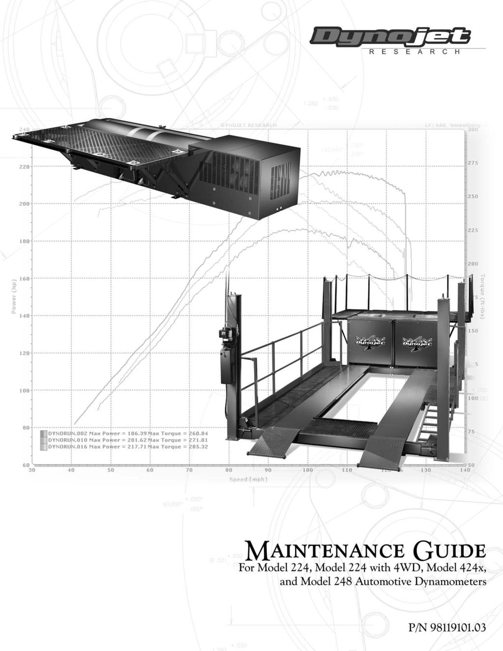
Maintenance Guide For Model 224, Model 224 with 4WD, Model 424x, and Model 248 Automotive Dynamometers.
|
|
|
- Henry Ryan
- 5 years ago
- Views:
Transcription
1
2 Dynojet Research, Inc. All Rights Reserved. Maintenance Guide For Model 224, Model 224 with 4WD, Model 424x, and Model 248 Automotive Dynamometers. This manual is copyrighted by Dynojet Research, Inc., hereafter referred to as Dynojet, and all rights are reserved. This manual is furnished under license and may only be used or copied in accordance with the terms of such license. This manual is furnished for informational use only, is subject to change without notice, and should not be construed as a commitment by Dynojet. Dynojet assumes no responsibility or liability for any error or inaccuracies that may appear in this manual. Except as permitted by such license, no part of this manual may be reproduced, stored in a retrieval system, or transmitted, in any form or by any means, electronic, mechanical, recording, or otherwise, without the prior written permission of Dynojet. The Dynojet logo is a trademark of Dynojet Research, Inc. Any trademarks, trade names, service marks, or service names owned or registered by any other company and used in this guide are the property of their respective companies. Dynojet Research, Inc., 2191 Mendenhall Drive, North Las Vegas, Nevada 89031, USA. Printed in USA. Part Number: Version 3 (03/2008)
3 TABLE OF CONTENTS Auto Dyno Maintenance Introduction Conventions Used In This Manual Technical Support Model 224 Dynos with Air Over HyDraulic (AOH) Brake Systems Things to Check Maintaining the Model 224 AOH Drum Brake Shoe Clearance Model 224 Dynos with Spring Applied Air Release (SAAR) Brake System. 6 Things to Check Verifying the SAAR Brake Pressure Maintaining the SAAR Brake Shoe Clearance Changing the SAAR Brake Shoes WD Attachment for Model 224 Dynos Things to Check Filling the Air Motor Lubricator Adjusting the Air Motor Lubricator Inspecting the Rail Brake Clearance Model 424x All-Wheel Drive Dynos Things to Check Filling the Air Motor Lubricator Adjusting the Air Motor Lubricator Verifying the SAAR Brake Pressure Maintaining the SAAR Brake Shoe Clearance Changing the SAAR Brake Shoes Checking the Air Can Sleeve Retraction Model 248 Dynos Things to Check Checking the 248 Drum Brake Shoe Clearance i
4

5 This document provides instructions for performing maintenance on the model 224 dynamometer (dyno), the model 224 dyno with the four wheel drive (4WD) attachment, the model dyno, the model 424x dyno, and the model 248 dyno. To ensure safety and accuracy in the procedures, perform the procedures as they are described. Document Part Number: Version 3 Last Updated:
6 Introduction INTRODUCTION You may have a model 224 dyno configured with one drum for testing two-wheel drive vehicles, or with two drums for testing four-wheel drive vehicles. Model 224 dynos also may use either the Air Over Hydraulic (AOH) brake or the Spring Applied Air Release brake (SAAR). Model 424x dynos all use the SAAR brake and have two dyno drums for testing four-wheel drive cars. Or you may have a model 248 dyno. Make sure to perform all of the maintenance procedures for your dyno configuration. CONVENTIONS USED IN THIS MANUAL The conventions used in this manual are designed to protect both the user and the equipment. example of convention description The Caution icon indicates a potential hazard to the dynamometer equipment. Follow all procedures exactly as they are described and use care when performing all procedures. The Warning icon indicates potential harm to the person performing a procedure and/or the dynamometer equipment. TECHNICAL SUPPORT For assistance, please contact Dynojet Technical Support at , or write to Dynojet at 2191 Mendenhall Drive, North Las Vegas, NV Visit us on the World Wide Web at where Dynojet provides state of the art technical support, on-line shopping, and press releases about our latest product line. 2
7 Model 224 Dynos with Air Over HyDraulic (AOH) Brake Systems MODEL 224 DYNOS WITH AIR OVER HYDRAULIC (AOH) BRAKE SYSTEMS This section covers maintenance items for model 224 dynos with a single drum and AOH braking. AD203 Figure 1: Model 224 with Air Over Hydraulic (AOH) Brakes THINGS TO CHECK Check all air fittings for leaks monthly. Correct any leaks found. Once per month verify that the drum brake pressure gauge reads 55 to 65psi ( kPa). Adjust the regulator if the pressure is out of specification. Once per month check the drum brake shoe clearance. Refer to page 4 for more information. Dyno Bearing Grease: Under steady use, over 25 runs per day, each bearing should receive.65oz (19 ml) of a recommended grease every 2 months. Under occasional use, less than 25 runs per day, each bearing should receive.65oz (19 ml) of a recommended grease every six months. Recommended Grease: grease specification description thickener Lithium 12 Hydroxy Stearate oil Petroleum thickness NLGI 2 operating temperature -20 F to 200 F, intermittent to 250 F (Fahrenheit) operating temperature -29 C to 93 C, intermittent to 121 C (Celsius) EP additive yes examples Mobil Mobilith AW-2 Version 3 3
8 Model 224 Dynos with Air Over HyDraulic (AOH) Brake Systems MAINTAINING THE MODEL 224 AOH DRUM BRAKE SHOE CLEARANCE The 224 AOH drum brake shoe clearance must be checked once per month. If you have upgraded your 224 dyno to use the Spring Applied Air Release (SAAR) braking system, refer to Maintaining the SAAR Brake Shoe Clearance on page 8. 1 Remove the air from the system. 1a Shut off or disconnect the air supply to the dyno, and follow lock out procedure. 1b Press the red button on the pendant to activate the drum brakes; the button will be lit. 1c Using the red button on the pendant, cycle the drum brakes on and off several times until all of the air is released from the system. 2 Remove the covers as necessary to provide safe working access to the dyno. 3 Measure the gap between the brake shoe and the drum surface. This gap should be.125 inch inch (3mm - 10mm). 4 If the brake shoe clearance is out of specification, perform the following steps: 4a Remove the two 3/8-inch bolts and washers that secure the brake slave cylinder to the dyno frame. AD204 remove bolts and washers remove bolts and washers Figure 2: 224 Dyno AOH Brake Remove the Bolts from Brake Slave Cylinder 4
9 Model 224 Dynos with Air Over HyDraulic (AOH) Brake Systems 4b 4c 4d 4e Pull the slave cylinder away from the dyno being careful not to kink the brake line. Screw the brake piston rod in to increase brake shoe clearance or out to decrease brake shoe clearance. Refer to Figure 3. Attach the slave cylinder using the bolts and washers removed earlier. Recheck the brake shoe clearance. No part of the brake shoe should touch the drum. Note: If you cannot adjust the brakes to specification, you will need new brake shoes. Contact Dynojet. 5 Turn on or reconnect the air supply and verify the drum brakes operate before replacing the covers and using the dyno. AD205 screw brake piston rod in or out to adjust brake clearance carefully pull slave cylinder away to expose the brake piston rod Figure 3: 224 Dyno AOH Brake Pull the Cylinder Away Version 3 5
10 Model 224 Dynos with Spring Applied Air Release (SAAR) Brake System MODEL 224 DYNOS WITH SPRING APPLIED AIR RELEASE (SAAR) BRAKE SYSTEM This section covers maintenance items for model 224 dynos with the SAAR brake. THINGS TO CHECK Check all air fittings for leaks monthly. Correct any leaks found. Once per month verify the drum brake pressure gauge reads 100psi (690kPa). Adjust the regulator if the pressure is out of specification. Refer to Verifying the SAAR Brake Pressure on page 7 for more information. Check the drum brake shoe clearance. Refer to Maintaining the SAAR Brake Shoe Clearance on page 8 for more information. Dyno Bearing Grease: Under steady use, over 25 runs per day, each bearing should receive.65oz (19 ml) of a recommended grease every 2 months. Under occasional use, less than 25 runs per day, each bearing should receive.65oz (19 ml) of a recommended grease every six months. Recommended Grease: grease specification description thickener Lithium 12 Hydroxy Stearate oil Petroleum thickness NLGI 2 operating temperature -20 F to 200 F, intermittent to 250 F (Fahrenheit) operating temperature -29 C to 93 C, intermittent to 121 C (Celsius) EP additive yes examples Mobil Mobilith AW-2 6
11 Model 224 Dynos with Spring Applied Air Release (SAAR) Brake System VERIFYING THE SAAR BRAKE PRESSURE 1 Verify the SAAR brake pressure gauge reads 100psi (690kPa). 2 Using the knob, adjust the regulator until the correct pressure is achieved. brake pressure regulator AB096 use knob to adjust regulator until correct pressure is achieved 0 AB095 Figure 4: 224 Dyno Verify the SAAR Brake Pressure and Adjust Using the Regulator brake pressure gauge should read 100psi (690kPA) Version 3 7
12 Model 224 Dynos with Spring Applied Air Release (SAAR) Brake System MAINTAINING THE SAAR BRAKE SHOE CLEARANCE 1 Verify the area is clear and the dyno can be operated safely. 2 Power up the dyno electronics. 3 Using the pendant, turn the brake to the off position. This will release the SAAR brake by moving the brake shoe away from the drum. Keep hands and fingers clear when operating dyno. 4 Measure the gap between the brake shoe and the drum surface. This gap should be between.125 inch inch (3mm - 10mm). Note: For clarity, the dyno frame is shown transparently to reveal the drum. Note: The mounting bracket shown is used with the SAAR upgrade. Factory installed SAAR brakes use a slightly different bracket. brake shoe drum measure gap AB094 Figure 5: 224 SAAR Brake Measure the Gap Between the Brake Shoe and Drum 8
13 Model 224 Dynos with Spring Applied Air Release (SAAR) Brake System 5 If the brake shoe clearance is out of specification, loosen the upper nut on the air can rod. 6 Adjust the lower nut until the brake shoes are.25 inch (6mm) away from the dyno drum. 7 Tighten the upper nut on the air can rod down onto the brake actuating tube to sandwich the tube between the two nuts. 8 Torque the lower nut to 110 foot-pounds. If you cannot adjust the brakes to specification, you will need new brake shoes. Contact Dynojet. air can rod upper nut brake actuating tube BR032 lower nut Figure 6: 224 SAAR Brake Adjust the Brake Shoe Clearance Version 3 9
14 Model 224 Dynos with Spring Applied Air Release (SAAR) Brake System CHANGING THE SAAR BRAKE SHOES 1 Apply air to the brake system. Air pressure to the brake system must be maintained while changing the SAAR brake shoes. 2 Release the brakes. 2a Turn on the dyno electronics. 2b Verify the brake button on the pendant is not lit. 3 Remove the nut from the bottom air can rod and set aside. air can rod nut Figure 7: 224 SAAR Brake Remove the Nut from the Bottom Air Can Rod 10
15 Model 224 Dynos with Spring Applied Air Release (SAAR) Brake System 4 Slowly lower the pressure using the regulator. The air can rod will retract from the tube. Note: Verify the rod does not bind on the tube. regulator air can rod tube Figure 8: 224 SAAR Brake Retract the Air Can Rod from the Tube Version 3 11
16 Model 224 Dynos with Spring Applied Air Release (SAAR) Brake System 5 Slide the tube out and set aside. tube Figure 9: 224 SAAR Brake Slide the Tube Out 6 Using the access holes in the dyno frame, remove the cotter key from each brake. 7 Remove the pin from each brake. Note: For clarity, the drum is not shown. pin top view drum not shown for clarity cotter key Figure 10: 224 SAAR Brake Remove the Cotter Key and Pin 12
17 Model 224 Dynos with Spring Applied Air Release (SAAR) Brake System 8 Remove each brake arm assembly. brake arm assembly Figure 11: 224 SAAR Brake Remove the Brake Arm Assembly 9 Remove the cotter key from the brake arm assembly. 10 Remove the pin. 11 Remove the retainer and shoe. 12 Install the new brake shoe and replace the retainer. Note: Verify the brake shoe is secure. 13 Replace the pin and cotter key. brake shoe retainer cotter key pin brake shoe retainer cotter key pin Figure 12: 224 SAAR Brake Replace the Brake Shoe Version 3 13
18 Model 224 Dynos with Spring Applied Air Release (SAAR) Brake System 14 Replace each brake arm assembly using the pin and cotter key removed earlier. Refer to Figure Slide the tube in. 16 Slowly raise the pressure using the regulator. The air can rod will go through the tube. Note: Verify the rod does not bind on the tube. regulator air can rod tube Figure 13: 224 SAAR Brake Replace the Air Can Rod Through the Tube 14
19 Model 224 Dynos with Spring Applied Air Release (SAAR) Brake System 17 Replace the nut, removed earlier, on the bottom air can rod. 18 Adjust the brake shoe clearance as necessary. Refer to Maintaining the SAAR Brake Shoe Clearance on page 8 for more information. 19 Press the red button on the pendant to activate the drum brakes; the button will be lit. air can rod nut Figure 14: 224 SAAR Brake Replace the Nut on the Bottom Air Can Rod Version 3 15
20 4WD Attachment for Model 224 Dynos 4WD ATTACHMENT FOR MODEL 224 DYNOS This section covers maintenance items for model 224 dynos with the 4WD attachment. THINGS TO CHECK Check customer supplied air filter/dryer daily, empty and clean as necessary. Inspect the 4WD dyno movement rails for debris once per month. Clear any debris from the rails. Check all air fittings for leaks monthly. Correct any leaks found. Once per month maintain the brake pressure and brake shoe clearance. For AOH brakes refer to page 3. If you have upgraded to the SAAR brake, see page 6. Adjust the lubrication provided by the air motor lubricator. Refer to Adjusting the Air Motor Lubricator on page 18 for more information. Check the air motor lubricator once per month and fill as necessary. Refer to Filling the Air Motor Lubricator on page 17 for more information. Dyno Bearing Grease: Under steady use, over 25 runs per day, each bearing should receive.65oz (19 ml) of a recommended grease every 2 months. Under occasional use, less than 25 runs per day, each bearing should receive.65oz (19 ml) of a recommended grease every six months. Recommended Grease: grease specification description thickener Lithium 12 Hydroxy Stearate oil Petroleum thickness NLGI 2 operating temperature -20 F to 200 F, intermittent to 250 F (Fahrenheit) operating temperature -29 C to 93 C, intermittent to 121 C (Celsius) EP additive yes examples Mobil Mobilith AW-2 16
21 4WD Attachment for Model 224 Dynos FILLING THE AIR MOTOR LUBRICATOR Check the air motor lubricator once per month and fill as necessary. 1 Disconnect the air before removing the lubricator bowl. 2 Shut off or disconnect the air supply to the dyno, and follow lock out procedure. 3 Press and hold the dyno in or out movement switch until you cannot hear any air going through the movement motor. 4 Before running the Gast Air Motor, remove the lubricator bowl and fill the bowl with oil. Note: Use a non-detergent SAE #10 automotive engine oil (Gast Part #AD220). BR043 remove bowl and fill to line with oil Figure 15: 224 4WD Attachment Check Air Motor Lubricator Version 3 17
22 4WD Attachment for Model 224 Dynos ADJUSTING THE AIR MOTOR LUBRICATOR Use the following steps to adjust the amount of oil provided by the air motor lubricator. 1 Turn the top knob on the air motor lubricator clockwise until it shuts off the flow of oil. 2 Back off the knob one turn counter-clockwise to start the flow of oil. 3 Adjust the knob as needed between one turn and fully on (turning counterclockwise) as needed for the particular environment in your dyno room. turn knob clockwise to shut off oil, back off one turn counterclockwise to start the flow of oil AD206 Figure 16: 224 4WD Attachment Adjust the Air Motor Lubricator 18
23 4WD Attachment for Model 224 Dynos INSPECTING THE RAIL BRAKE CLEARANCE Inspect the rail brake clearance once per month. 1 Shut off or disconnect the air supply to dyno, and follow your company s lock out procedure. 2 Press the red button on the pendant to activate the drum brakes; the button will be lit. 3 Press and hold the dyno movement switch in either the in or out position until you cannot hear any air going through the movement motor. 4 Using the red button on the pendant, cycle the drum brakes on and off several times until no air is heard. 5 Remove the covers as necessary to provide safe working access to the dyno. 6 Using a ruler, measure the free play movement of each rail brake. The free play should not exceed 3/16 inch (5mm). 7 If the rail brake free play is out of specification, adjust by loosening the jam nut and turning the adjusting bolt until free play is within specification. Tighten the jam nut while holding the adjusting bolt. Figure 17: 224 4WD Attachment Inspect the Rail Brake Clearance Version 3 19
24 Model 424x All-Wheel Drive Dynos MODEL 424X ALL-WHEEL DRIVE DYNOS This section covers maintenance items for model 424x dynos. THINGS TO CHECK Check all air fittings for leaks monthly. Correct any leaks found. Check the air motor lubricator once per month and fill as necessary. Refer to Filling the Air Motor Lubricator on page 21 for more information. Once per month verify that the SAAR brake pressure gauge reads 100psi (690kPa). Adjust the regulator if the pressure is out of specification. Refer to Verifying the SAAR Brake Pressure on page 23 for more information. Check the drum brake clearance. Refer to Maintaining the SAAR Brake Shoe Clearance on page 24 for more information. Check the air can sleeve retraction. Refer to Checking the Air Can Sleeve Retraction on page 26 for more information. Check customer supplied air filter/dryer daily, empty and clean as necessary. Inspect the 4WD dyno movement rails for debris once per month. Clear any debris from the rails. Dyno Bearing Grease: Under steady use, over 25 runs per day, each bearing should receive.65oz (19 ml) of a recommended grease every 2 months. Under occasional use, less than 25 runs per day, each bearing should receive.65oz (19 ml) of a recommended grease every six months. Recommended Grease: grease specification description thickener Lithium 12 Hydroxy Stearate oil Petroleum thickness NLGI 2 operating temperature -20 F to 200 F, intermittent to 250 F (Fahrenheit) operating temperature -29 C to 93 C, intermittent to 121 C (Celsius) EP additive yes examples Mobil Mobilith AW-2 20
25 Model 424x All-Wheel Drive Dynos FILLING THE AIR MOTOR LUBRICATOR Check the air motor lubricator once per month and fill as necessary. 1 Disconnect the air before removing the lubricator bowl. 2 Shut off or disconnect the air supply to the dyno, and follow lock out procedure. 3 Press and hold the dyno in or out movement switch until you cannot hear any air going through the movement motor. 4 Before running the Gast Air Motor, remove the lubricator bowl and fill the bowl with oil. Note: Use a non-detergent SAE #10 automotive engine oil (Gast Part #AD220). remove bowl and fill to line with oil Figure 18: 424x Dyno Filling the Air Motor Lubricator AD0195 Version 3 21
26 Model 424x All-Wheel Drive Dynos ADJUSTING THE AIR MOTOR LUBRICATOR Use the following steps to adjust the amount of oil provided by the air motor lubricator. 1 Turn the top knob on the air motor lubricator clockwise until it shuts off the flow of oil. 2 Back off the knob one turn counter-clockwise to start the flow of oil. 3 Adjust the knob as needed between one turn and fully on (turning counterclockwise) as needed for the particular environment in your dyno room. turn knob to adjust amount of oil delivered Figure 19: 424x Dyno Adjusting the Air Motor Lubricator AD
27 Model 424x All-Wheel Drive Dynos VERIFYING THE SAAR BRAKE PRESSURE 1 Verify the SAAR brake pressure gauge reads 100psi (690kPa). 2 Using the knob, adjust the regulator until the correct pressure is achieved. brake pressure regulator AB096 use knob to adjust regulator until correct pressure is achieved 0 AB095 Figure 20: 424x Dyno Check the SAAR Brake Pressure and Adjust the Regulator brake pressure gauge should read 100psi (690kPA) Version 3 23
28 Model 424x All-Wheel Drive Dynos MAINTAINING THE SAAR BRAKE SHOE CLEARANCE 1 Verify the area is clear and the dyno can be operated safely. 2 Power up the dyno electronics. 3 Using the pendant, turn the brake to the off position. This will release the SAAR brake by moving the brake shoe away from the drum. Keep hands and fingers clear when operating dyno. 4 Measure the gap between the brake shoe and the drum surface. This gap should be between.125 inch inch (3mm - 10mm). Note: For clarity, the dyno frame is shown transparently to reveal the drum. Note: The mounting bracket shown is used with the SAAR upgrade. Factory installed SAAR brakes use a slightly different bracket. brake shoe drum measure gap AB094 Figure 21: 424x SAAR Brake Measure the Gap Between the Brake Shoe and Drum 24
29 Model 424x All-Wheel Drive Dynos 5 If the brake shoe clearance is out of specification, loosen the upper nut on the air can rod. 6 Adjust the lower nut until the brake shoes are.25 inch (6mm) away from the dyno drum. 7 Tighten the upper nut on the air can rod down onto the brake actuating tube to sandwich the tube between the two nuts. 8 Torque the lower nut to 110 foot-pounds. If you cannot adjust the brakes to specification, you will need new brake shoes. Contact Dynojet. air can rod upper nut brake actuating tube BR032 lower nut Figure 22: 424x SAAR Brake Adjust the Brake Shoe Clearance CHANGING THE SAAR BRAKE SHOES Refer to Changing the SAAR Brake Shoes on page 10 for detailed instructions. Version 3 25
30 Model 424x All-Wheel Drive Dynos CHECKING THE AIR CAN SLEEVE RETRACTION The SAAR brake s air can sleeve must be positioned correctly for safe operation. If the air can sleeve is not in the correct location, use a wrench and loosen the nut as far as you can. The sleeve will drop down as shown in Figure 23. Check all four air cans. Note: Verify that the brakes are operating properly before replacing the covers and using the dyno. correct placement of nut and sleeve incorrect placement of nut and sleeve sleeve sleeve nut nut AD0194 Figure 23: 424x Dyno Air Can Sleeve 26
31 Model 248 Dynos MODEL 248 DYNOS This section covers maintenance items for model 248 dynos. THINGS TO CHECK Check all air fittings for leaks monthly. Correct any leaks found. Once per month verify the drum brake pressure gauge is reading 55 to 65psi (450kPa). Adjust the regulator if the pressure is out of specification. Maintain the brake shoe clearance. Refer to Checking the 248 Drum Brake Shoe Clearance on page 28 for more information. Dyno Bearing Grease: Under steady use, over 25 runs per day, each bearing should receive 1.5oz (44.36 ml) of a recommended grease every 2 months. Under occasional use, less than 25 runs per day, each bearing should receive 1.5oz (44.36 ml) of a recommended grease every six months. Recommended Grease: grease specification description thickener Lithium Complex oil Petroleum thickness NLGI 2 operating temperature -20 F to 200 F, intermittent to 250 F (Fahrenheit) operating temperature -29 C to 93 C, intermittent to 121 C (Celsius) examples Mobil Mobilith AW-2 Version 3 27
32 Model 248 Dynos CHECKING THE 248 DRUM BRAKE SHOE CLEARANCE The 248 drum brake shoe clearance needs to be checked once per month. Use the following steps. 1 Remove the air from the system. 1a Shut off or disconnect the air supply to the dyno, and follow lock out procedure. 1b Press the red button on the pendant to activate the drum brakes; the button will be lit. 1c Press and hold the dyno in or out movement switch until you cannot hear any air going through the movement motor. Note: If there is no 4WD dyno, skip this step. 1d Using the red button on the pendant, cycle the drum brakes on and off several times until no air is heard. 2 Remove the covers as necessary to provide safe working access to the dyno. 3 Measure the gap between the brake shoe and the drum surface. This gap should be.125 inch -.50 inch (3mm - 13mm). 28
33 Model 248 Dynos 4 If the brake shoe clearance is out of specification perform the following steps: 4a 4b 4c 4d 4e 4f 4g 4h Remove the cotter key from the clevis pin and remove clevis pin. Remove the two 5/8-inch nuts and washers securing the air can to the brake bracket. Loosen the jam nut. Pull the air can up so that the clevis can be turned. Screwing the clevis down the air can rod will decrease brake shoe clearance. With the clevis adjusted, secure the jam nut. Place the air can on brake bracket and secure with nuts and washers removed earlier. Secure clevis with pin and cotter key. Adjust the brake shoe support so that the brake shoe clearance is even over the length of the shoe. Loosen the jam nut and turn the brake shoe support. With the brake shoe support adjusted, tighten the jam nut. If you cannot adjust the brakes to specification, you will need new brake shoes. Contact Dynojet. 5 Turn on or reconnect the air supply and check that the drum brakes operate before replacing the covers and using the dyno. Figure 24: 248 Dyno Remove Cotter Key Version 3 29
34
35
2006 Dynojet Research, Inc. All Rights Reserved. Spring Applied Air Release (SAAR) Brake Assembly Installation
 Brake Assembly Installation") 2006 Dynojet Research, Inc. All Rights Reserved. This manual is copyrighted by Dynojet Research, Inc., hereafter referred to as Dynojet, and all rights are reserved. This manual, as well as the software
2006 Dynojet Research, Inc. All Rights Reserved. This manual is copyrighted by Dynojet Research, Inc., hereafter referred to as Dynojet, and all rights are reserved. This manual, as well as the software
Power Carriage Installation Guide
 Power Carriage Installation Guide 1999-2002 Dynojet Research, Inc. All Rights Reserved. 020116SD Dynojet Research, Inc. 200 Arden Drive Belgrade, MT 59714 2191 Mendenhall Drive North Las Vegas, NV 89031
Dynojet Research, Inc. All Rights Reserved. Tire Temperature Sensor Installation Guide
 1998-2006 Dynojet Research, Inc. All Rights Reserved. This manual is copyrighted by Dynojet Research, Inc., hereafter referred to as Dynojet, and all rights are reserved. This manual, as well as the software
Torque Cell Installation Guide for Model 250i/250iP DynoWare RT Dynamometers.
 2015 Dynojet Research, Inc. All Rights Reserved. Torque Cell Installation Guide for Model 250i/250iP DynoWare RT Dynamometers. This manual is copyrighted by Dynojet Research, Inc., hereafter referred to
Dynojet Research, Inc. All Rights Reserved. Air Fuel Ratio Module Installation and User Guide.
 2014-2015 Dynojet Research, Inc. All Rights Reserved.. This manual is copyrighted by Dynojet Research, Inc., hereafter referred to as Dynojet, and all rights are reserved. This manual, as well as the software
Dynojet Research, Inc. All Rights Reserved. Optical RPM Sensor Installation Guide.
 1993-2001 Dynojet Research, Inc. All Rights Reserved.. This manual is copyrighted by Dynojet Research, Inc., hereafter referred to as Dynojet, and all rights are reserved. This manual, as well as the software
Torque Module Installation and User Guide for model 250i Motorcycle Dynamometers.
 2000-2005 Dynojet Research, Inc. All Rights Reserved. Torque Module Installation and User Guide for model 250i Motorcycle Dynamometers. This manual is copyrighted by Dynojet Research, Inc., hereafter referred
Air Fuel Ratio Module and AFR-4 Pump Assembly Installation and User Guide.
 2007-2012 Dynojet Research, Inc. All Rights Reserved.. This manual is copyrighted by Dynojet Research, Inc., hereafter referred to as Dynojet, and all rights are reserved. This manual, as well as the software
Harley-Davidson and the Bar & Shield logo are among the trademarks of H-D Michigan, LLC.
 2010-2012 Dynojet Research, Inc. All Rights Reserved. Harley-Davidson JUMPSTART Intallation and User Guide This manual is copyrighted by Dynojet Research, Inc., hereafter referred to as Dynojet, and all
Linx System with Atra Flex Installation for Model 424 Automotive Dynamometers
 2009-2018 Dynojet Research, Inc. All Rights Reserved. Linx System with Atra Flex Installation for Model 424 Automotive Dynamometers This manual is copyrighted by Dynojet Research, Inc., hereafter referred
Control Panel Interface Upgrade Installation Guide For Model 200i and 250i Motorcycle Dynamometers Serial Number 202xxxx.
 2004 Dynojet Research, Inc. All Rights Reserved. Control Panel Interface Upgrade Installation Guide For Model 200i and 250i Motorcycle Dynamometers Serial Number 202xxxx. This manual is copyrighted by
Sea Doo 4-Tec Supercharged 1500cc Watercraft (Throttle By Wire models) Dynojet CMDM-6212
 Dynojet CMDM-6212") 2009-2012 Sea Doo 4-Tec Supercharged 1500cc Watercraft (Throttle By Wire models) Dynojet CMDM-6212 2012 Dynojet Research, Inc. All Rights Reserved. 2009-2012 Sea Doo 4-Tec Supercharged 1500cc Watercraft
2009-2012 Sea Doo 4-Tec Supercharged 1500cc Watercraft (Throttle By Wire models) Dynojet CMDM-6212 2012 Dynojet Research, Inc. All Rights Reserved. 2009-2012 Sea Doo 4-Tec Supercharged 1500cc Watercraft
INSTALLATION GUIDE. Dynojet Research 2191 Mendenhall Drive Suite 105, North Las Vegas NV,
 INSTALLATION GUIDE www.dynojetwb2.com Dynojet Research 2191 Mendenhall Drive Suite 105, North Las Vegas NV, 89081 1-800-992-4993 2008 Dynojet Research, Inc. All Rights Reserved. Wideband 2 Installation
Motorcycle Dynamometer Installation Guide
 Motorcycle Dynamometer Installation Guide 1993-2002 Dynojet Research, Inc. All Rights Reserved. 020329SD Dynojet Research, Inc. 200 Arden Drive Belgrade, MT 59714 2191 Mendenhall Drive North Las Vegas,
Installation Guide for Above Ground Model 224 Automotive Dynamometers.
 2005-2014 Dynojet Research, Inc. All Rights Reserved. Installation Guide for Above Ground Model 224 Automotive Dynamometers. This manual is copyrighted by Dynojet Research, Inc., hereafter referred to
1994 Mazda MX-5 Miata. BRAKE SYSTEM 1994 BRAKES Mazda - Disc & Drum BRAKES Mazda - Disc & Drum
 BRAKE PEDAL FREE PLAY 1994 Mazda MX-5 Miata DESCRIPTION & OPERATION BRAKE SYSTEM 1994 BRAKES Mazda - Disc & Drum NOTE: For information on anti-lock brake systems, see ANTI-LOCK BRAKE SYSTEM article in
DP556 Pump. 55:1, Air-operated, Grease. General. Operation. Technical Data. Installation. Mounting with Reinforced Cover (Recommended)
") DP556 Pump 55:1, Air-operated, Grease General The DP556 Pump is a compressed air-operated reciprocating piston pump. This high capacity demand pump is compatible with mineral and synthetic grease and suitable
DP556 Pump 55:1, Air-operated, Grease General The DP556 Pump is a compressed air-operated reciprocating piston pump. This high capacity demand pump is compatible with mineral and synthetic grease and suitable
Eddy Current Brake Installation and User Guide For Model 224 Above Ground Automotive Dynamometers.
 2004-2008 Dynojet Research, Inc. All Rights Reserved. Eddy Current Brake Installation and User Guide For Model 224 Above Ground Automotive Dynamometers. This manual is copyrighted by Dynojet Research,
PNEUMATICS CONTENTS HST-TAMPER
 CONTENTS Tamper Pneumatic Component Locations...2 Manually Releasing Air Brakes... 3 Releasing Air Pressure... 4 Removing Water from Air Tanks... 4 Adjusting Air Compressor Governor... 4 Check/Replace
Installation Guide for In Ground Model 224 Automotive Dynamometers.
 2014-2015 Dynojet Research, Inc. All Rights Reserved. Installation Guide for In Ground Model 224 Automotive Dynamometers. This manual is copyrighted by Dynojet Research, Inc., hereafter referred to as
HexPro Series Low Profile Wrenches
 HexPro Series Low Profile Wrenches Operation and Maintenance Manual Model 2HP 4HP 8HP 14HP 30HP www.torquetoolsinc.com Use the HEXPRO Series Low Profile Wrenches Model 2HP 4HP 8HP 14HP 30HP to install
 Operation and Maintenance Manual Model.75,, 3, 5, 8, 0, 0, 5, 35, 50 http://www.torsionx.com Use the MaxDrv Series Square Drive Torque Wrench Model.75,, 3, 5, 8, 0, 0, 5, 35, 50 to install and remove threaded
Models Affected: Certain 2013 Model Year Propane Vision Buses Equipped with Ford 6.8L Engines CORRECTIVE ACTION ---- PROCEDURE
 Models Affected: Certain 2013 Model Year Propane Vision Buses Equipped with Ford 6.8L Engines ISSUE Certain 2013 model year propane Vision buses equipped with Ford 6.8L engines may not have the service
 Operation and Maintenance Manual http://www.torsionx.eu Use the MaxDrv Series Square Drive Torque Wrench Model.75, 1, 3, 5, 8, 10, 20, 25, 35, 50 to install and remove threaded fasteners requiring precise
Installation and Operation Manual
 1645 Lemonwood Dr. Santa Paula, CA 93060 USA Toll Free: 1 (800) 253-2363 Tel: 1 (805) 933-9970 rangerproducts.com Ranger Floor Jack Installation and Operation Manual Manual Revision B July 2017 Manual
Cummins 6.7 Litre 2500/3500 Diesel EGR System. Always wear gloves and safety glasses when performing this service
 Cummins 6.7 Litre 2500/3500 Diesel EGR System Always wear gloves and safety glasses when performing this service EGR System Consists of: Cold side EGR valve (after EGR cooler) controls exhaust gases for
IBT Series Square Drive Torque Wrenches
 IBT Series Square Drive Torque Wrenches Operation and Maintenance Manual Model.75, 1, 3, 5, 8, 10, 20, 25, 35, 50 http://www.torsionx.com Use the IBT Series Square Drive Torque Wrenches Model.75, 1, 3,
Service Bulletin Trucks Date Number Page
 Mack Trucks, Inc. Allentown, PA USA (Also applies to Mack Trucks Australia, Operation and Adjustment Only, CXX, CLX, CMH, CMM and CSM Models) (Supersedes SB313005 dated 03/24/08) Service Bulletin Trucks
SmarTire TPMS Maintenance Hand Tool. Revision User Manual
 SmarTire TPMS Maintenance Hand Tool Revision 1.03 User Manual Page 2 Table of Contents FCC Compliance Label...4 User Interface Illustration...4 Introduction...5 Testing Tire Sensors...5 Main Menu...6 Main
Eddy Current Brake Installation and User Guide For Model 224 Pit Automotive Dynamometers.
 2004-2005 Dynojet Research, Inc. All Rights Reserved. Eddy Current Brake Installation and User Guide For Model 224 Pit Automotive Dynamometers. This manual is copyrighted by Dynojet Research, Inc., hereafter
RUFNEX Series Low Profile Wrenches Operation and Maintenance Manual
 RUFNEX Series Low Profile Wrenches Operation and Maintenance Manual http://www.torsionx.com Use the RUFNEX Series Ultra-Low Profile Wrenches to install and remove large bolts that have minimal wrench clearance.
Slack Adjuster. Table of Contents
 Slack Adjuster Table of Contents Sub-Headings Automatic Slack Adjuster Service 2 PayMaster Automatic Slack Adjuster 2 How the Automatic Slack Adjuster Works 2 Pressed-In, Sealed Actuator Boot 3 Handed
XP-AIR Multi-Port Power Pack Operation and Maintenance Manual
 XP-AIR Multi-Port Power Pack Operation and Maintenance Manual http://www.torsionx.com Safety Guide To use the XP-AIR Multi-Port Power Pack safely you must follow correct operation guidelines and inspect
Baumann Series Flexsleev Control Valve Instructions
 Instruction Baumann 86000 Series Instructions Baumann 86000 Series Flexsleev Control Valve Instructions Contents Introduction...1 Scope...1 Safety Precautions...1 Maintenance...2 Installation...3 Air Piping...3
BRAKE SYSTEM Article Text 1992 Mitsubishi Mirage For a a a a a Copyright 1998 Mitchell Repair Information Company, LLC Monday, April 01, :05AM
 Article Text ARTICLE BEGINNING 1992 BRAKES Chrysler Motors/Mitsubishi - Disc & Drum Chrysler Motors: Colt, Colt 200, Colt Vista, Ram-50, Stealth, Summit, Summit Wagon; Mitsubishi: Diamante, Eclipse, Expo/Expo
Embedded Rack Slide-out System
 Embedded Rack Slide-out System SERVICE MANUAL Rev: 02.16.2017 Page 1 Electric Embedded Rack Slide-out System TABLE OF CONTENTS Safety Information 3 Product Information 3 Operation 4 Extending Slide-Out
Low Profile Wrenches Operation and Maintenance Manual
 Low Profile Wrenches Operation and Maintenance Manual http://www.torquetoolsinc.com Use the HEXPRO Series Low Profile Wrenches Model 2HP 4HP 8HP 14HP 30HP to install and remove large bolts that have minimal
Operating Manual & Safety Instructions ProTorc Hydraulic Torque Wrench Model # PTLC - Please read in full before operating ProTorc Torque Wrench -
 Operating Manual & Safety Instructions ProTorc Hydraulic Torque Wrench Model # PTLC - Please read in full before operating ProTorc Torque Wrench - ProTorc Important Safety Instructions READ ALL INSTRUCTIONS
Hydro-Sync Slide-Out System
 Hydro-Sync Slide-Out System SERVICE MANUAL Rev: 08.14.2018 Hydro-Sync Slide-out System Service Manual TABLE OF CONTENTS Safety Information 3 Product Information 3 Operation 4 Extending Slide-Out Room 4
PLOW MOUNT GLACIER PRO KIT
 PLOW MOUNT GLACIER PRO KIT P/N 2880262 APPLICATION FOR USE WITH THE GLACIER PRO MID-SIZE PLOW SYSTEM (P/N 2880260) ON 2015 AND NEWER RZR 00 MODELS BEFORE YOU BEGIN Read these instructions thoroughly and
Eddy Current Brake Installation and User Guide For In Ground Model 224 Automotive Dynamometers.
 2004-2008 Dynojet Research, Inc. All Rights Reserved. Eddy Current Brake Installation and User Guide For In Ground Model 224 Automotive Dynamometers. This manual is copyrighted by Dynojet Research, Inc.,
Tech Note Truck 14 & 15.5 Twin Plate Cast Iron Type Installation Guidelines
 1. (14 & 15.5 ) Check condition of the flywheel. Grind to resurface or replace flywheel. Surface MUST BE machined or premature clutch failure can occur. Flywheel depth must be 2.938 (74.62mm) for 14 (350mm)
Air-Assist Service Jack Max. Capacity: 10 Tons
 Form No. 565786 Parts List & Operating Instructions for: 1511B Air-Assist Service Jack Max. Capacity: 10 Tons 109 67 66 68 77 69 70 78 95 94 107 106 108 26 71 72 72 93 X L 65 75 92 91 90 89 88 87 86 85
Product Customization Guide TSE Brakes, Inc.
 Revision Date: June 7, 2018 Revision: 4 Page: 1 of 13 CONTENTS Brake Chamber Clamp Repositioning Instructions 2-3 Mechanical Release of Spring Brakes (Caging) 4-6 Installation Instructions 7-9 Determine
SmarTire TPMS Maintenance Hand Tool. Revision User Manual
 SmarTire TPMS Maintenance Hand Tool Revision 1.04 User Manual Page 2 Table of Contents FCC Compliance Label... 4 User Interface Illustration... 4 Introduction... 5 Testing Tire Sensors... 5 Main Menu...
Index. Page Number Section
 S H O C K S Index Page Number Section 1-4 GM Front Coil Over Installation 5-7 Front Smooth Body Shock Installation 7-8 Rear Smooth Body Shock Installation 8-11 Custom Coil Over Installation 12 Tuning and
CRD600 Automatic Fitting Inserter
 CRD600 Automatic Fitting Inserter OPERATIONS MANUAL VERSION 2.3 LAST EDITED 12.07.2018 cleanroomdevices.com 1 Table of Contents Title Page.. 1 Table of Contents. 2 1.0 General Product & Safety Information...3
CRD610 Automatic Fitting Inserter
 CRD610 Automatic Fitting Inserter OPERATIONS MANUAL VERSION 1.2 LAST EDITED 12.12.2018 cleanroomdevices.com 1 Table of Contents Title Page. 1 Table of Contents...2 1.0 General Product & Safety Information....3
XP-115 Multi-Port Power Pack Operation and Maintenance Manual
 XP-115 Multi-Port Power Pack Operation and Maintenance Manual http://www.torsionx.com Safety Guide To use the XP-115 Multi-Port Power Pack safely you must follow correct operation guidelines and inspect
OPERATION AND MAINTENANCE
 Table of Contents GENERAL INFORMATION INTRODUCTION... 1 Operating Specifications... 1 FEATURES... 1 SAFETY PRECAUTIONS... 2 SET-UP... 2 OPERATION AND MAINTENANCE TESTING AN IGNITION MODULE OR IGNITION
CLEAN ROOM DEVICES, LLC "WHERE TUBING AND FITTINGS COME TOGETHER"
 CLEAN ROOM DEVICES, LLC "WHERE TUBING AND FITTINGS COME TOGETHER" CRD600AF Automatic Fitting Inserter With Auto Feed OPERATIONS MANUAL (Shown with optional alcohol dispenser) 1 VERSION 1.1 LAST EDITED
MGM Brakes Service Manual
 MGM Brakes Service Manual MAGNUM Performance Plus Spring Brake Actuators (MJ-Series 3.00 / 76mm Long Stroke ) For: S-Cam Tamper-Resistant MAGNUM Performance Plus Spring Brake Actuators Figure 1 A B C Your
Bucket Grease Pump ASSEMBLY AND OPERATING INSTRUCTIONS
 Bucket Grease Pump 9793 ASSEMBLY AND OPERATING INSTRUCTIONS 349 Mission Oaks Blvd., Camarillo, CA 930 Visit our Web site at http://www.harborfreight.com Copyright 2004 by Harbor Freight Tools. All rights
1999 Toyota RAV BRAKES Disc & Drum - Trucks & Vans
 DESCRIPTION & OPERATION 1999-2000 BRAKES Disc & Drum - Trucks & Vans WARNING: For warnings and procedures regarding vehicles equipped with Anti-Lock Brake Systems (ABS), see appropriate ANTI-LOCK article.
Lifting height 5.5" - 72" with adapters " Height overall 165" Width between columns 122" Drive through 109" Width overall 151.
 Model Number TP12KC-D Capacity 12,000 lbs. Lifting height 5.5" - 72" with adapters 79.625" Height overall 165" Width between columns 122" Drive through 109" Width overall 151.125" Arm extension 37.5" -
5874SS/5874PB/5874PBF/VRK5874/PBA6/ PBA6HPB/PBA7 Valve/Push Button
 INSTALLATION, OPERATION & MAINTENANCE INSTRUCTIONS 1455 Kleppe Lane Sparks, NV 89431-6467 (775) 359-4712 Fax (775) 359-7424 E-mail: haws@hawsco.com website: www.hawsco.com No. 2077650(1) 5874SS/5874PB/5874PBF/VRK5874/PBA6/
L Rev. 10/04. CSI Midland/Gunite Automatic Brake Adjuster Service Manual
 L30006 Rev. 10/04 CSI Midland/Gunite Automatic Brake Adjuster Service Manual TABLE OF CONTENTS Overview...3 Installation Procedures...4 Brake Adjustment...10 Installation Procedures...11 Brake Adjustment...13
Model DFR 070/156/220 Rotary Actuator
 Figure 1 DFR 156 TABLE OF CONTENTS General 2 Actuator Assembly 18 Scope 2 Bushing / Yoke Assembly 18 Principles of Operation 2 Spring Barrel Assembly 18 Safety Caution 2 Diaphragm Plate Assembly 20 Specifications
Brake System H TX, H2.0TXS [B475]; H TX [B466] Safety Precautions Maintenance and Repair
![Brake System H TX, H2.0TXS [B475]; H TX [B466] Safety Precautions Maintenance and Repair](/thumbs/86/93834005.jpg "Brake System H TX, H2.0TXS [B475]; H TX [B466] Safety Precautions Maintenance and Repair") HMM180001 Brake System H1.5-1.8TX, H2.0TXS [B475]; H2.5-3.5TX [B466] Safety Precautions Maintenance and Repair When lifting parts or assemblies, make sure all slings, chains, or cables are correctly fastened,
HMM180001 Brake System H1.5-1.8TX, H2.0TXS [B475]; H2.5-3.5TX [B466] Safety Precautions Maintenance and Repair When lifting parts or assemblies, make sure all slings, chains, or cables are correctly fastened,
XPS-ProFeed Shuttle SERVICE MANUAL. Revised:
 XPS-ProFeed Shuttle SERVICE MANUAL Revised: 9-14-15 RENA SYSTEMS INC. 910 East Main Street; Suite 200 Norristown, PA 19401-4110 Phone: (610) 650-9170 Fax: (610) 270-3947 Web Site: www.renausa.com SAFETY
On-Vehicle Service Hub and Drum Assembly. Remove or Disconnect (Figures 1, 3-5) 1 of 8 11/25/2016 2:47 PM
 1 of 8 11/25/2016 2:47 PM") 1 of 8 11/25/2016 2:47 PM On-Vehicle Service Hub and Drum Assembly Remove or Disconnect (Figures 1, 3-5) Tools Required: J-35012 Rear Hub Bearing Nut Wrench J-35013 Rear Hub Remover 1. Remove the drain
1 of 8 11/25/2016 2:47 PM On-Vehicle Service Hub and Drum Assembly Remove or Disconnect (Figures 1, 3-5) Tools Required: J-35012 Rear Hub Bearing Nut Wrench J-35013 Rear Hub Remover 1. Remove the drain
Pleasereadandfulyunderstandthisprocedurepriortoperforminganybearingmaintenance.
 Pleasereadandfulyunderstandthisprocedurepriortoperforminganybearingmaintenance. Thismanualoutlinesgeneraldirectionsforbearingmaintenanceusingtestedefective techniques.additionaly,alcommonandacceptedsafetypracticesaretobefolowedin
TH!NK neighbor Section 2 Chassis Section 2 Chassis
 General Specifications... 2 Torque Specifications... 2 Description and Operation... 4 Wheel Alignment Angles... 4 Brakes... 4 Diagnosis and Testing... 6 Ball Joint Inspection... 6 Wheel Bearing Inspection...
INSTALLATION / OPERATING INSTRUCTIONS Reese Elite Series FIFTH WHEEL SLIDER HITCH
 INSTALLATION / OPERATING INSTRUCTIONS Reese Elite Series FIFTH WHEEL SLIDER HITCH DEALER/INSTALLER: (1) Provide this Manual to end user. (2) Physically demonstrate hitching and unhitching procedures in
V46 and V47. Repair Parts and Service Instructions. Applications. Adjustments. Installation Guidelines
 Applications The V46 pressure-actuated and V47 temperatureactuated water-regulating valves are used for water-cooled condensers, bypass service on refrigeration systems, engine cooling, and various industrial
Installation Manual TWM Performance Full replacement short shifter assembly Civic all trims and models
 Installation Manual TWM Performance Full replacement short shifter assembly 2006+ Civic all trims and models Begin the installation by parking on a flat surface, as you will have to engage and disengage
Service Jack. Form No Parts List & Operating Instructions 1510B. Max. Capacity: 5 and 10 Tons. 1 of 3. Sheet No. Issue Date: Rev.
 SPX Corporation 655 Eisenhower Drive Owatonna, MN 55060-0995 USA Phone: (507) 455-7000 Tech. Serv.: (800) 533-6127 Fax: (800) 955-8329 Order Entry: (800) 533-6127 Fax: (800) 283-8665 International Sales:
AUTOMATIC CLUTCH Models
 AUTOMATIC CLUTCH 1940 Models Source of this material is from 1940 Series, Issue 4, January 1940 Hudson Service Magazine AUTOMATIC CLUTCH 1940 MODELS The automatic clutch installation and adjustment procedure
INTEGRATED1500LB WINCH KIT
 INTEGRATED1500LB WINCH KIT P/N 2882798 APPLICATION Verify accessory fitment at Polaris.com. BEFORE YOU BEGIN Read these instructions and check to be sure all parts and tools are accounted for. Please retain
1991 TRANSMISSION SERVICING Automatic Transmission. Mitsubishi: Eclipse, Galant, Mirage, Montero, Pickup, Precis, 3000GT
 Article Text ARTICLE BEGINNING 1991 TRANSMISSION SERVICING Automatic Transmission Mitsubishi: Eclipse, Galant, Mirage, Montero, Pickup, Precis, 3000GT IDENTIFICATION MITSUBISHI AUTOMATIC TRANSMISSION APPLICATIONS
Clutch Installation Guide
 Clutch Installation Guide 0 STOP! READ CAREFULLY BEFORE INSTALLING CLUTCH This clutch must be installed by a qualified installer. Improper installation or failure to replace or resurface the flywheel,
PRODUCT OPERATING MANUAL
 PRODUCT OPERATING MANUAL PANBLAST TM BP110 3 BLAST POT Manual Number: ZVP PC 0155 00 SECTION 1. GENERAL INFORMATION 2. INITIAL SETUP INSTRUCTIONS 3. OPERATING INSTRUCTIONS 4. MAINTENANCE 5. TROUBLE SHOOTING
Air Brake Inspection Presented By: G.L. May
 Air Brake Inspection 2012 Presented By: G.L. May Outline of this course Objective of this course: The technician will have a better understanding of requirements for air drum brakes and air disc brakes
PRODUCT OPERATING MANUAL
 PRODUCT OPERATING MANUAL PANBLAST TM BP50 3 BLAST POT Manual Number: ZVP PC 0156 00 SECTION 1. GENERAL INFORMATION 2. INITIAL SETUP INSTRUCTIONS 3. OPERATING INSTRUCTIONS 4. MAINTENANCE 5. TROUBLE SHOOTING
OPERATION AND MAINTENANCE MANUAL
 WREN IBT SERIES HYDRAULIC TORQUE WRENCHES IBT SQUARE DRIVE SERIES OPERATION AND MAINTENANCE MANUAL FOR WREN Products: POINT 75, 1IBT, 3IBT, 5IBT, 8IBT, 10IBT, 20IBT, 25IBT, 35IBT, 50IBT SQUARE DRIVE HYDRAULIC
CONTENTS FIGURES GETTING STARTED 1 1 FUNCTIONS AND PARTS LISTS K Series Service Manual
 CREDITS/COPYRIGHT 2001-2002 Best Lock Corporation dba Best Access Systems. All rights reserved. Printed in the United States of America. Information in this document is subject to change without notice
OnBoard Drum Major Podium
 Assembly and Owner s Manual OnBoard Drum Major Podium CONTENTS CONTENTS................................................................................. 1 SAFETY...................................................................................
Micro-Injection System
 QUIK-- Micro-Injection System Table of Contents Part 1: Getting Started & Using your QUIK-jet Air Parts of the QUIK-jet Air Device...2 Parts of the QUIK-jet Air Kit...3 Air Tank Assembly...4 Connecting
GBP784B INSTALLATION TOOL
 GBP784B INSTALLATION TOOL GAGE BILT MADE IN U.S.A. GAGE BILT PRODUCTS CORP. 14500 Barber Drive (586) 771-7664 Warren, Mi 48088 (586) 771-2665 Fax e-mail:solutions@gagebilt.com / www.gagebilt.com TABLE
ALUMINUM JACK. 3,000 lb. Jack Capacity & JACK STAND COMBO. Model ASSEMBLY AND OPERATING INSTRUCTIONS
 ALUMINUM JACK 3,000 lb. Jack Capacity & JACK STAND COMBO 6,000 lb. Jack Stand Capacity (when used in pairs) Model 91850 ASSEMBLY AND OPERATING INSTRUCTIONS 3491 Mission Oaks Blvd., Camarillo, CA 93011
Installing the Integral Platen Blow Off Valve
 Instruction Sheet Installing the Integral Platen Blow Off Valve WARNING: Allow only qualified personnel to perform the following tasks. Observe and follow the safety instructions in this document and all
NOTE: THIS INFORMATION APPLIES TO VEHICLES EQUIPPED WITH A 5.9L DIESEL ENGINE.
 SUBJECT: NO: 11-08-98 Turbo Diesel Wastegate Actuator GROUP: Exhaust Repair Kit DATE: Sep. 25, 1998 MODELS: 1994-1998 (BR/BE) Ram Truck THIS INFORMATION APPLIES TO VEHICLES EQUIPPED WITH A 5.9L DIESEL
B14 AAA FINE FINISH SERIES PUMP OUTFIT
 PRODUCT INFORMATION B14 AAA FINE FINISH SERIES PUMP OUTFIT The B14 AAA pump system is an air assisted airless unit which combines airless and conventional or HVLP air atomization technologies to produce
IOM FOR DYNATORQUE D-LOCK LOCKING DEVICE (DL TYPE)
") Scope: It is the purpose of this document to provide general installation, operation, and maintenance instructions for the DYNATORQUE D-Lock locking device. Design: All Cameron DYNATORQUE operators and
Scope: It is the purpose of this document to provide general installation, operation, and maintenance instructions for the DYNATORQUE D-Lock locking device. Design: All Cameron DYNATORQUE operators and
INSTALLATION INSTRUCTIONS FOR THE TRUCK MOUNTED VIPER ADDITIVE INJECTION SYSTEM GTP-8776C
 INSTALLATION INSTRUCTIONS FOR THE TRUCK MOUNTED VIPER ADDITIVE INJECTION SYSTEM GTP-8776C This additive injection system was designed to be used with five gallon jug of additive. The system is supplied
Installation instructions for the FC6 Forward Controls for Suzuki Marauder 800
 Installation instructions for the FC6 Forward Controls for Suzuki Marauder 800 It is highly recommended that you use a thread lock compound such as Loctite on all threads to keep them from vibrating loose.
GLACIER PRO RANGER MID SIZE MOUNT KIT
 GLACIER PRO RANGER MID SIZE MOUNT KIT P/N 2880261 APPLICATION FOR USE WITH THE GLACIER PRO MID SIZE PLOW SYSTEM (P/N 2880260) ON 2010 AND NEWER RANGER MID SIZE MODELS BEFORE YOU BEGIN Read these instructions
Premium wheel-end brake products
 Premium wheel-end brake products Spicer Automatic Slack Adjuster Service Manual Self Adjusting Brake Adjuster The description and specifications contained in this service publication are current at the
3-in-1 Electric Jack, Impact Wrench & Air Compressor
 Item No. : 7010 3-in-1 Electric Jack, Impact Wrench & Air Compressor User s Manual We are constantly improving our products so specifications are subject to change without notice. Visit our website for
Air Collet Closer - Upgrade - OL-1
 LAST UPDATED: 11/26/2018 Air Collet Closer - Upgrade - OL-1 AD0062 Applies to machines built from: May, 2010 Introduction 1 This procedure tells you how to install the Office Lathe air collet closer (ACC)
GPS Steering System Installation Manual
 GPS Steering System Installation Manual Supported Vehicles Challenger Massey Ferguson AGCO MT-645C, MT-645D MF-8650 DT-205B MT-655C, MT-655D MF-8660 DT-225B MT-665C, MT-665D MF-8670 DT-250B MT-675C, MT-675D
CHAMBER CUSTOMIZATION GUIDE TSE
 Revision Date: May 6, 2011 Revision: 3 Page: 1 of10 CONTENTS Brake Chamber Clamp Repositioning Instructions...2-3 Mechanical Release of Spring Brakes (Caging)...4-6 Determine The Correct Push Rod Length...7-9
PNEUMATIC SLIDING VALVE
 INSTALLATION, OPERATION, & #: MM-SV001 6-23-09 Rev. A Page 1 of 8 PNEUMATIC SLIDING VALVE PART NUMBERS (Including, but not inclusive) SV704MSTS, SV714MSTS, SV754MSTS, SV764MSTS, SV774MSTS, SV706MSTS, SV716MSTS,
SuperTrac. Axle. Service & Maintenance. Manual
 SuperTrac Axle Service & Maintenance Manual Table of Contents Page Exploded Views Section 1: General Information General Warnings Description of Axle Models Identifications Section 2: Installation Axle
ZF 6HP19X / 6HP21X 6HP19X 6HP21X. Automatic Transmission Spare Parts Catalog
 ZF 6HP19X / 6HP21X 6HP19X 6HP21X Automatic Transmission Spare Parts Catalog Warranty Information Warranty coverage for ZF passenger car transmission spare parts and kits covers the first 12 months after
MODEL T26746 FOOT-OPERATED GREASE PUMP INSTRUCTIONS
 MODEL T26746 FOOT-OPERATED GREASE PUMP INSTRUCTIONS For questions or help with this product contact Tech Support at (570) 546-9663 or techsupport@grizzly.com Introduction The Model T26746 Foot-Operated
CLEAN ROOM DEVICES, LLC "WHERE TUBING AND FITTINGS COME TOGETHER"
 CLEAN ROOM DEVICES, LLC "WHERE TUBING AND FITTINGS COME TOGETHER" CRD600 Automatic Fitting Inserter OPERATIONS MANUAL VERSION 2.1 LAST EDITED 7.25.14 DOCUMENT NUMBER 001 cleanroomdevices.com 1 Table of
Automotive Air Conditioning Manifold Gauge Sets
 Automotive Air Conditioning Manifold Gauge Sets 1 Caution: These instructions are not for use with Hybrid Vehicles. For instructions for servicing Hybrid Vehicles use Hybrid Vehicle manufacturer s service
B14 AAA FINE FINISH SERIES PUMP OUTFIT
 PRODUCT INFORMATION B14 AAA FINE FINISH SERIES PUMP OUTFIT The B14 AAA pump system is an air assisted airless unit which combines airless and conventional or HVLP air atomization technologies to produce
Cam Brakes. Table of Contents
 Sub-Headings Introduction 3 Q Plus 3 Disassembly 4 Remove the Wheel Components 4 Automatic Slack Adjuster 4 Brake Shoes 5 Remove Camshaft and Auto Slack Adjuster 6 Preparing Parts for Assembly 6 Clean