COBB CAMSHAFTS INSTALLATION Impreza RS/TS
|
|
|
- Brice Parsons
- 5 years ago
- Views:
Transcription
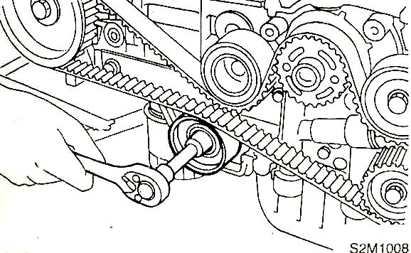
1 4673 South Cherry St. Salt Lake City, UT USA COBB CAMSHAFTS INSTALLATION Impreza RS/TS Congratulations on your purchase of Cobb Camshafts. The following instructions should assist you through your installation process. Please read them first before beginning the install. If you feel that you can not properly perform this installation, we HIGHLY recommend you take the vehicle to a qualified mechanic. Also, make sure all components are clear of manufacturing residue and packing materials before installation. PARTS LIST Instructions/Parts List... COBB Camshafts (2)... New Cam Seals (2)... Assembly Lube... Packed By... Date... TOOLS NEEDED The following tools are required: 22mm, 17mm, 14mm, 12mm, and 10mm Sockets TORX PLUS Socket (TORX 45 is close) 5mm and 2mm Hex Wrench Breaker Bar White paint marker Hydraulic Press Three Bond 1280B or other high quality liquid gasket Feeler Gauges ( and ) Torque Wrench Air wrench (recommended) Timing Belt Removal 1. Disconnect Battery. 2. Remove electric fans and overflow tank on radiator. 3. Loosen crankshaft pulley bolt (22mm) but to not remove yet. 4. Remove accessory belts. 5. Remove crankshaft pulley. 6. Remove A/C belt tensioner. 7. Remove timing belt covers. 8. Remove timing belt guide located directly above crankshaft pulley. 9. Using 22mm crankshaft pulley bolt, rotate crankshaft until cam sprocket marks align with marks on cylinder head and/or belt cover notch. (FIGURE 1)
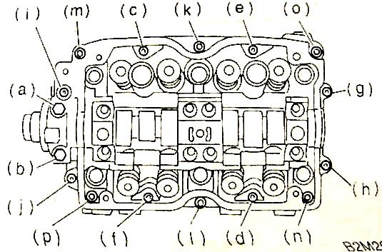
2 10. Mark timing belt according to marks on RH cam sprocket, LH cam sprocket, and crankshaft with white paint which will be used for installation. 11. Loosen 17mm bolts for camshaft sprockets but do not remove. 12. Remove timing belt idler pulley (No. 2). (FIGURE 2) 13. Removing timing belt. 14. Removing automatic belt tension adjuster assembly. Cam Removal 1. Remove intake assembly and windshield washer tank to gain access to valve covers. 2. Remove spark plug wires and blow-by hoses from valve covers. 3. Doing one side at a time, place suitable oil catch container under vehicle and remove valve cover bolts (5 bolts) to remove cover. 4. Next, remove valve rocker arm assembly. Follow alphabetic sequence in Figure 3 to loosen the bolts. Be careful not to damage assembly. 5. Remove camshaft sprocket. 6. Remove camshaft cap following alphabetic sequence in Figure 4. Take care not to strip out the small hex bolts. 7. Run a razorblade between camshaft cap and cylinder head to cut the factory installed liquid gasket and release the cap from the cylinder head. Be careful not to let the camshaft drop out when removing the camshaft cap. DO NOT attempt to pry the cap off with a screwdriver or you might cause serious damage to the soft aluminum parts. 8. Remove camshaft and rear camshaft plug from assembly. Camshaft Install 1. Clean old liquid gasket material off camshaft cap and cylinder head. Use compressed air to blow away any debris from the cylinder head. 2. Using assembly lube supplied with camshaft, coat new camshaft journals and lobes to protect camshaft during initial break in. 3. Prepare camshaft cap by applying liquid gasket to the camshaft cap according to Figure Install camshaft and rear camshaft cap. 5. While holding camshaft and rear plug in place, install camshaft cap and temporarily tighten bolts (g) through (j) to secure the assembly. (FIGURE 4) 6. Apply small amount of assembly lube to rollers at the end of the rocker arms. Install valvetrain assembly and tighten bolts in alphabetical sequence to 18 ft-lbs of torque. (FIGURE 3) 7. Tighten TORX bolts (k) through (p) on camshaft cap in alphabetical sequence to 13 ft-lbs of torque. (FIGURE 4) 8. Tighten 5mm Hex bolts (c) through (j) on camshaft cap, in alphabetical sequence, to 7 ftlbs of torque. 9. Finally, tighten the remaining two bolts (a) and (b) on the camshaft cap to 7 ft-lbs of torque. 10. Apply coat of assembly lube to new camshaft oil seal (supplied with cam) and install oil seal to camshaft. Use large diameter, thin-walled deep socket, or other suitable tool to press seal in place. 11. Install rear timing belt cover and sensor (LH) and both camshaft sprockets. Torque camshaft sprocket bolts to 58 ft-lbs. 12. For now, leave the valve covers off. Timing Belt Install 1. Place Automatic Belt Tension Adjuster assembly into hydraulic press and slowly push adjuster rod down. Press the rod gradually taking more than three minutes. Once
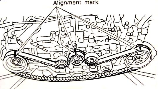
3 compressed, use a 2mm hex wrench inserted into the stopper pen hold in the cylinder to secure the adjuster rod. (FIGURES 6 & 7) 2. Install Automatic Belt Tension Adjuster to block. Tighten bolt to 29 ft-lbs of torque. 3. Turn camshaft sprockets to position their alignment marks with those on the engine. (FIGURE 8) 4. Once camshaft sprockets and crankshaft is in position, install the timing belt. Use your old alignment marks on belt to ensure belt alignment and direction are correct. (FIGURE 9) 5. Install idler pulley (No. 2). Tighten to 29 ft-lbs of torque. 6. Double check alignment marks on timing belt. If correct, remove stopper pin (2mm hex wrench) from belt tensioner. 7. Install timing belt guide located above crankshaft pulley. Use feeler gauge to set distance from belt to guide at / Valve Clearance 1. Turn engine clockwise through two full rotations. 2. Set #1 cylinder to Top Dead Center (Figure 10), and check the valve clearances. Intake: Exhaust: (Figure 11) 3. If adjustment is needed, loosen nut with 10mm wrench and turn screw until clearance is set. When done, tighten nut with holding screw in position. (TORQUE: 7 ft-lbs) 4. Repeat adjustment procedures for #2, #3, and #4 cylinders. (FIGURE 10) Covers and Accessories 1. Install valve covers to cylinder heads. Tighten bolts to 4 ft-lbs of torque. 2. Install timing belt cover. Tighten bolts to 4 ft-lbs of torque. 3. Install Crankshaft Pulley. Tighten bolt to 130 ft-lbs of torque. 4. Install A/C Idler pulley assembly. 5. Install belts. 6. Install electric fans and overflow tank to radiator. 7. Install spark plug wires and blow-by hoses to valve covers. 8. Install intake system assembly and windshield washer bottle. 9. Change oil. Recommend using premium grade petroleum based motor oil. Using synthetic during break in process is not recommended. 10. Reconnect battery. Camshaft Break In 1. Start car and fast idle at 2000 RPM for 15 minutes. Have assistant check for any leaks. 2. Once car has idled for 15 minutes, you can perform a test drive to ensure there are no leaks or problems. 3. After 3000 miles, it s recommend that you change the oil and check the valve clearances again. Some adjustment is typically required, as the camshaft will break in and your valve clearance will change. Have fun and enjoy the added performance from your new COBB Tuning Performance Camshafts.

4 Figure 1 Figure 2

5 Figure 3 Figure 4

6 Figure 5 Figure 6 Figure 7

7 Figure 8 Figure 9

8 Figure 10 Figure 11
15.Timing Belt Assembly
 MECHANICAL 15.Timing Belt Assembly A: REMOVAL 1. TIMING BELT 1) Remove the V-belt. 2) Remove the crank pulley.
15.Timing Belt. Timing Belt A: REMOVAL ME(STI) TIMING BELT
 TIMING BELT") 15.Timing Belt A: REMOVAL NOTE: Perform the work with the engine installed to body when replacing a single part. For operation procedures, refer to Timing Belt in the PM section.
15.Timing Belt A: REMOVAL NOTE: Perform the work with the engine installed to body when replacing a single part. For operation procedures, refer to Timing Belt in the PM section.
15.Timing Belt. Timing Belt A: REMOVAL ME(H4DOTC) TIMING BELT
 TIMING BELT") 15. A: REMOVAL 1. TIMING BELT 1) Remove the V-belts. 2) Remove the crank pulley. 3) Remove the timing belt cover.
15. A: REMOVAL 1. TIMING BELT 1) Remove the V-belts. 2) Remove the crank pulley. 3) Remove the timing belt cover.
2. Timing Belt SERVICE PROCEDURE A: REMOVAL 1. CRANKSHAFT PULLEY AND BELT COVER. 1) Remove A/C belt. (With A/C model)
 Remove A/C belt. (With A/C model)") SERVICE PROCEDURE [W2A1] 2-3a A: REMOVAL 1. CRANKSHAFT PULLEY AND BELT COVER B2M2583A (1) Front side V-belt (2) Rear side V-belt (With A/C model) (3) Crankshaft pulley bolt (4) Crankshaft Pulley (5) Belt
SERVICE PROCEDURE [W2A1] 2-3a A: REMOVAL 1. CRANKSHAFT PULLEY AND BELT COVER B2M2583A (1) Front side V-belt (2) Rear side V-belt (With A/C model) (3) Crankshaft pulley bolt (4) Crankshaft Pulley (5) Belt
VALVE CLEARANCE (1NZ-FXE)
") 146 ENGINE MECHANICAL ADJUSTMENT 1. REMOVE REAR FLOOR BOARD NO.2 (See page 211 16) 2. REMOVE DECK FLOOR BOX REAR (See page 211 16) 3. REMOVE REAR FLOOR BOARD NO.3 (See page 211 16) 4. DISCONNECT BATTERY
146 ENGINE MECHANICAL ADJUSTMENT 1. REMOVE REAR FLOOR BOARD NO.2 (See page 211 16) 2. REMOVE DECK FLOOR BOX REAR (See page 211 16) 3. REMOVE REAR FLOOR BOARD NO.3 (See page 211 16) 4. DISCONNECT BATTERY
1 of 17 2/19/ :10 AM TIMING BELT
 1 of 17 2/19/2012 11:10 AM TIMING BELT 2 of 17 2/19/2012 11:10 AM INSTALLATION SPROCKET 1) Install right-hand belt cover No.2. 3 of 17 2/19/2012 11:10 AM 2) Install left-hand belt cover No.2. 3) Install
 Special Tools Needed: DrVanos.com Stage I Installation Instructions Camshaft locking tool TDC Crank pin Sprocket turning tool Tool rental is available with the purchase of a vanos kit *See website for
15.Timing Belt Assembly
 15.Timing Belt Assembly A: REMOVAL 1. TIMING BELT 1) Remove the V-belt. 2) Remove the crankshaft pulley. 3)
11.Preparation for Overhaul
 11.Preparation for Overhaul A: PROCEDURE 1) After removing the engine from body, secure it in the ST shown below. ST1 498457000 ENGINE STAND ADAPTER RH ST2 498457100 ENGINE STAND ADAPTER LH ST3 499817000
Service and Repair SERVICE POINTS OF REMOVAL. Select Vehicle New TSBs Technician's Reference Mitsubishi 3000GT V6-2972cc 3.
 1 of 12 5/4/2008 10:31 PM Home Account Contact ALLDATA Log Out Help METRO TOYOTA Select Vehicle New TSBs Technician's Reference 1992 Mitsubishi 3000GT V6-2972cc 3.0L DOHC Vehicle Level Engine, Cooling
REMOVAL AND REPLACEMENT
 2002 Mitsubishi Truck Montero LTD 4WD V6-3.5L SOHC Vehicle > Engine, Cooling and Exhaust > Engine > Timing Components > Timing Belt > Service and Repair REMOVAL AND REPLACEMENT https://my.alldata.com/repair/#/repair/article/36847/component/64/itype/401/nonstandard/
VALVE CLEARANCE (K3-VE)
") ENGINE MECHANICAL VALVE CLEARANCE (K3-VE) 25 ENGINE MECHANICAL VALVE CLEARANCE (K3-VE) INSPECTION 1. DISCONNECT NEGATIVE BATTERY TERMINAL (See page RS-164.) 2. ROVE ENGINE UNDER COVER 3. DRAIN ENGINE COOLANT
ENGINE MECHANICAL VALVE CLEARANCE (K3-VE) 25 ENGINE MECHANICAL VALVE CLEARANCE (K3-VE) INSPECTION 1. DISCONNECT NEGATIVE BATTERY TERMINAL (See page RS-164.) 2. ROVE ENGINE UNDER COVER 3. DRAIN ENGINE COOLANT
DrVanos.com Stage II Installation Instructions. Tool rental is available with the purchase of a vanos kit *See website for more info*
 DrVanos.com Stage II Installation Instructions Special Tools Needed: Camshaft locking tool TDC Crank pin Sprocket turning tool Tool rental is available with the purchase of a vanos kit *See website for
26/01/2017 3GR-FSE ENGINE MECHANICAL: ENGINE UNIT: DISASSEMBLY; 2006 MY GS300 [01/ ]
![26/01/2017 3GR-FSE ENGINE MECHANICAL: ENGINE UNIT: DISASSEMBLY; 2006 MY GS300 [01/ ]](/thumbs/85/92233007.jpg "26/01/2017 3GR-FSE ENGINE MECHANICAL: ENGINE UNIT: DISASSEMBLY; 2006 MY GS300 [01/ ]") Last Modified: 8-24-2016 6.6 A Doc ID: RM000000T4X000X Model Year Start: 2006 Model: GS300 Prod Date Range: [01/2005 - ] Title: 3GR-FSE ENGINE MECHANICAL: ENGINE UNIT: DISASSEMBLY; 2006 MY GS300 [01/2005
Last Modified: 8-24-2016 6.6 A Doc ID: RM000000T4X000X Model Year Start: 2006 Model: GS300 Prod Date Range: [01/2005 - ] Title: 3GR-FSE ENGINE MECHANICAL: ENGINE UNIT: DISASSEMBLY; 2006 MY GS300 [01/2005
EM 6 VALVE CLEARANCE ENGINE MECHANICAL EM11I 01 ADJUSTMENT HINT:
 EM6 ADJUSTMENT EM11I01 Inspect and adjust the valve clearance when the engine is cold. 1. REMOVE NO.1 ENGINE UNDER COVER 2. DRAIN ENGINE COOLANT 3. REMOVE AIR CLEANER INLET 4. REMOVE AIR CLEANER ASSEMBLY
15.Timing Chain Assembly
 15. A: REMOVAL 1. TIMING CHAIN RH When replacing a single part, perform the work with the engine assembly installed to body. 1) Remove the chain cover. 2) Using
2001 Mitsubishi Truck Montero LTD 4WD V6-3.5L SOHC Copyright 2006, ALLDATA 8.80 Page 1. Timing Belt: Service and Repair
 2001 Mitsubishi Truck Montero LTD 4WD V6-3.5L SOHC Copyright 2006, ALLDATA 8.80 Page 1 Timing Belt: Service and Repair 2001 Mitsubishi Truck Montero LTD 4WD V6-3.5L SOHC Copyright 2006, ALLDATA 8.80 Page
BEW engine timing belt replacement procedure from MOGolf (as demonstrated on a 2004 Jetta).
.") BEW engine timing belt replacement procedure from MOGolf (as demonstrated on a 2004 Jetta). Based on the procedure published by Volkswagen, but modified for the "average" shadetree mechanic. Some special
BEW engine timing belt replacement procedure from MOGolf (as demonstrated on a 2004 Jetta). Based on the procedure published by Volkswagen, but modified for the "average" shadetree mechanic. Some special
2. Timing Belt. 2-3b [W2A1] SERVICE PROCEDURE A: REMOVAL 1. CRANKSHAFT PULLEY AND BELT COVER
![2. Timing Belt. 2-3b [W2A1] SERVICE PROCEDURE A: REMOVAL 1. CRANKSHAFT PULLEY AND BELT COVER](/thumbs/76/74262870.jpg "2. Timing Belt. 2-3b [W2A1] SERVICE PROCEDURE A: REMOVAL 1. CRANKSHAFT PULLEY AND BELT COVER") 2-3b [W2A1] SERVICE PROCEDURE A: REMOVAL 1. CRANKSHAFT PULLEY AND BELT COVER B2M1705C (1) V-belt (2) Crankshaft pulley bolt (3) Crankshaft pulley (4) Left-hand belt cover No. 1 (5) Right-hand belt cover
2-3b [W2A1] SERVICE PROCEDURE A: REMOVAL 1. CRANKSHAFT PULLEY AND BELT COVER B2M1705C (1) V-belt (2) Crankshaft pulley bolt (3) Crankshaft pulley (4) Left-hand belt cover No. 1 (5) Right-hand belt cover
IN-VEHICLE SERVICE. Engine Components
 file://c:\tso\tsocache\vdtom_5368\svk~us~en~file=svk31a14.htm~gen~ref.htm Page 1 of 10 Section 03-01A: Engine, 2.3L I-4 IN-VEHICLE SERVICE 1997 Ranger Workshop Manual Engine Components The views shown
3. Timing Belt 2-3 SERVICE PROCEDURE A: REMOVAL 1. CRANKSHAFT PULLEY AND BELT COVER
 SERVICE PROCEDURE 2-3 A: REMOVAL 1. CRANKSHAFT PULLEY AND BELT COVER G2M0107 1) Remove V-belt and A/C belt tensioner. 2) Remove pulley bolt. To lock crankshaft use ST. ST 499977000 CRANKSHAFT PULLEY WRENCH
2005 Saturn L ENGINE Engine Mechanical - 3.0L (L81) - L300
 - L300") Crankcase Vent Housing Removal Fig. 324: Removing & Installing Engine Vent Housing 1. Remove the hoses from the chamber. 2. Remove the chamber bolts. 3. Remove the chamber. 4. Remove the gasket material.
Crankcase Vent Housing Removal Fig. 324: Removing & Installing Engine Vent Housing 1. Remove the hoses from the chamber. 2. Remove the chamber bolts. 3. Remove the chamber. 4. Remove the gasket material.
Engine, disassembly and
 Page 1 of 13 13-1 Engine, disassembly and assembly Ribbed belt, removing and installing Removing - Remove noise insulation -arrows-. - Remove bumper Repair Manual, Body Exterior, Repair Group 63 - Move
Service Bulletin Trucks
 Mack Trucks, Inc. Greensboro, NC USA Service Bulletin Trucks Date Group No. Release Page This service bulletin replaces bulletin 214-93 dated 5.2010. 7.2013 214 93 02 1(13) Valves and Engine Injectors,
 Page 1 of 21 303-01C Engine 5.4L (3V) 2009 F-150 REMOVAL Procedure revision date: 03/26/2009 Cylinder Head Special Tool(s) 3 Jaw Puller 303-D121 or equivalent Compressor, Valve Spring 303-1039 Holding
Service Bulletin Cylinder Head Service. September 17, 2002
 Service Bulletin 02-047 Applies To: 1998 02 Passport ALL September 17, 2002 Cylinder Head Service BACKGROUND In the 1998 through 2002 Passport Service Manuals, some of the information on cylinder head
TORQUE SPECIFICATIONS
 2000 Suzuki Truck Grand Vitara LTD JLS 2WD V6-2.5L Vehicle > Engine, Cooling and Exhaust > Engine > Specifications > Mechanical TORQUE SPECIFICATIONS Engine Torque Specifications TORQUE COMPONENT TIGHTENING
1. Remove the crankshaft pulley, engine coolant pump pulley and drive belt. 2. Remove the timing belt cover.
 DISASSEMBLY 1. Remove the crankshaft pulley, engine coolant pump pulley and drive belt. 2. Remove the timing belt cover. 3. Turn the crankshaft clockwise and align the timing marks so as to bring the No.
Classification: Reference: Date: VE30DE CAM TIMING
 Classification: Reference: Date: EM93-002 NTB93-126 September 2, 1993 VE30DE CAM TIMING APPLIED VEHICLE(S): All equipped with VE30DE Engine SERVICE INFORMATION When servicing VE30DE engine cylinder heads,
TECHNICAL INSTRUCTIONS FOR SAFETY RECALL ALE VALVE SPRING AND LASH ADJUSTER REPLACEMENT GS 350: IS 350:
 TECHNICAL INSTRUCTIONS FOR SAFETY RECALL ALE VALVE SPRING AND LASH ADJUSTER REPLACEMENT GS 350: 2007 2008 IS 350: 2006 2008 I. OPERATION FLOWCHART Verify Vehicle Eligibility 1. Check the VIN range. 2.
2001 Chevrolet Metro LSi ENGINES 1.3L 4-Cylinder - Metro & Firefly (Canadian) Fig. 3: Exploded View Of Timing Belt & Components (Typical)
 Fig. 3: Exploded View Of Timing Belt & Components (Typical)") Fig. 3: Exploded View Of Timing Belt & Components (Typical) Fig. 4: Aligning Timing Marks 6. Loosen the timing belt tensioner bolt and the stud. 7. After pushing up the tensioner plate completely with
Fig. 3: Exploded View Of Timing Belt & Components (Typical) Fig. 4: Aligning Timing Marks 6. Loosen the timing belt tensioner bolt and the stud. 7. After pushing up the tensioner plate completely with
1992 Mitsubishi 3000GT VR-4
 TIMING BELT Removal (Diamante SOHC) 1. Remove left front and left side splash shields. Using engine hoist, lift engine just enough to remove weight from engine mounts. Remove drive belts. Remove A/C tensioner
88cc Big Bore Kit Install Instructions
 88cc Big Bore Kit Install Instructions Before installing a big bore kit, you should first install a high volume oil pump. A high volume oil pump will deliver up to 300% more oil to your top end which will
2002 Mitsubishi Montero Limited
 Fig. 9: Removing Drive Belt Auto Tensioner (2001-02 Montero) Sunday, December 07, 2008 2:19:07 2:19:11 PM Page 1 2005 Mitchell Repair Information Company, LLC. Fig. 10: Exploded View Of Timing Belt Components
CAMSHAFT (LH BANK) (2GR FE) ENGINE MECHANICAL 1424N 01 REPLACEMENT
 (2GR FE) ENGINE MECHANICAL 1424N 01 REPLACEMENT") REPLACEMENT N0. REMOVE ENGINE ASSEMBLY WITH TRANSAXLE (SEE PAGE ). REMOVE ENGINE WIRE 3. REMOVE FRONT FRAME ASSY (SEE PAGE ). REMOVE STARTER ASSY (SEE PAGE 99). REMOVE AUTOMATIC TRANSAXLE ASSY (SEE PAGE
REPLACEMENT N0. REMOVE ENGINE ASSEMBLY WITH TRANSAXLE (SEE PAGE ). REMOVE ENGINE WIRE 3. REMOVE FRONT FRAME ASSY (SEE PAGE ). REMOVE STARTER ASSY (SEE PAGE 99). REMOVE AUTOMATIC TRANSAXLE ASSY (SEE PAGE
DISASSEMBLY. Engine. CAUTION: Remove the cylinder heads before removing the crankshaft. Failure to do so can result in engine damage.
 303-01A-1 DISASSEMBLY Engine Special Tool(s) Remover, Crankshaft Vibration Damper 303-101 (T74P-3616-A) Special Tool(s) Crankshaft Socket 303-674 303-01A-1 Remover, Crankshaft Vibration Damper 303-773
2007 Ford Freestyle SEL
 Fig. 279: Exploded View Of Engine Heads, Intake & Exhaust Components Item Part Number Description 1 9D475 Exhaust gas recirculation (EGR) system module 2 9D477 EGR module tube 3 9F485 RH exhaust manifold
NUMBER: S.M. REF.: Listed in Table ENGINE: EPA07 Series 60 DATE: August 2013 SUBJECT: VALVE LASH ADJUSTMENTS ADDITIONS, REVISIONS, OR UPDATES
 NUMBER: 8 34 13 S.M. REF.: Listed in Table ENGINE: EPA07 Series 60 DATE: August 2013 SUBJECT: VALVE LASH ADJUSTMENTS ADDITIONS, REVISIONS, OR UPDATES Publication Number Platform Section Title Change DDC-SVC-MAN-0005
Timing Belt: Service and Repair
 2000 Hyundai Sonata L4-2.4L Page 1 Timing Belt: Service and Repair REMOVAL 1. Remove the crankshaft pulley, engine coolant pump pulley and drive belt. 2. Remove the timing belt cover. 2000 Hyundai Sonata
3. Using the ST, align the Top mark on crank sprocket to nine o clock position as shown in the figure
 2008 Tribeca (3.6L) MECHANICAL(H6DO) > Timing Chain Assembly Report a problem with this article INSTALLATION Be careful that the foreign matter is not into or onto assembled component during installation.
Remove four nuts, then the cooling fan assembly.
 The DOHC and SOHC engines both use the same Service and Repair procedure from Isuzu. Make note that the DOHC and SOHC engines both use a single gear for the camshaft but use different alignment marks.
1995 Mitsubishi Montero LS. Ensure timing marks are aligned. Mark timing belt direction of rotation.
 TIMING BELT NOTE: Ensure timing marks are aligned. Mark timing belt direction of rotation. Removal 1. Disconnect negative battery cable. Drain engine coolant. Remove engine coolant reservoir tank, fan
Recommended Installation Procedure (11 DEC 09) ATech Timing Belt Tensioner (979847/901) VW 1.6/2.0L L4 EA189 CR Engine
 ATech Timing Belt Tensioner (979847/901) VW 1.6/2.0L L4 EA189 CR Engine") Initial Preparation: Caution: The procedure to access the timing belt tensioner and all other timing driven components must be done according to VW s guidelines. The mounting of the TBT is done on the
Initial Preparation: Caution: The procedure to access the timing belt tensioner and all other timing driven components must be done according to VW s guidelines. The mounting of the TBT is done on the
REPLACEMENT HINT: 11. REMOVE V RIBBED BELT TENSIONER ASSY (a) Remove the 5 bolts and V ribbed belt tensioner.
 Remove the 5 bolts and V ribbed belt tensioner.") 14142 REPLACEMENT HINT: ENGINE MECHANICAL Refer to CAMSHAFT (RH BANK) or CAMSHAFT (LH BANK) for the replacement procedure of the No.2 chain (see page 14157 or 14175). 1. REMOVE ENGINE ASSEMBLY WITH TRANSAXLE
14142 REPLACEMENT HINT: ENGINE MECHANICAL Refer to CAMSHAFT (RH BANK) or CAMSHAFT (LH BANK) for the replacement procedure of the No.2 chain (see page 14157 or 14175). 1. REMOVE ENGINE ASSEMBLY WITH TRANSAXLE
1.8L & 2.2L 4-CYL Article Text 1998 Subaru Impreza
 1.8L & 2.2L 4-CYL Article Text 1998 Subaru Impreza ARTICLE BEGINNING 1995-98 ENGINES Subaru - 1.8L & 2.2L 4-Cylinder 1995-97: Impreza (1.8L) 1995-98: Impreza (2.2L), Legacy (2.2L) * PLEASE READ THIS FIRST
Ford Focus Zetec SVT Timing Belt
 2000-2004 Ford Focus Zetec SVT Timing Belt Replacement This guide will show you how to replace the timing belt on the 2.0L DOHC Zetec with VCT on a 2002 Ford Focus SVT. This is an interference motor. Written
Recommended Installation Procedure Timing Belt Tensioner (979597) 2.0L DOHC, RENAULT F4R Turbo, F4R L DOHC, RENAULT F4P720 (05/18/2004)
 2.0L DOHC, RENAULT F4R Turbo, F4R L DOHC, RENAULT F4P720 (05/18/2004)") Caution: The procedure to access the timing belt tensioner and all other timing driven components must be done according to the car manufacturer s guidelines. Engine temperature: 1. The tensioner must
Caution: The procedure to access the timing belt tensioner and all other timing driven components must be done according to the car manufacturer s guidelines. Engine temperature: 1. The tensioner must
1996 Isuzu Truck Rodeo (2WD) V6-3165cc 3.2L SOHC (6VD1)
 V6-3165cc 3.2L SOHC (6VD1)") 1996 Isuzu Truck Rodeo (2WD) V6-3165cc 3.2L SOHC (6VD1) Service and Repair Notes REMOVAL STEPS Preparation: Battery ground cable 1. Radiator upper fan shroud Remove from radiator. 2. Cooling fan assembly
1996 Isuzu Truck Rodeo (2WD) V6-3165cc 3.2L SOHC (6VD1) Service and Repair Notes REMOVAL STEPS Preparation: Battery ground cable 1. Radiator upper fan shroud Remove from radiator. 2. Cooling fan assembly
REMOVAL & INSTALLATION
 REMOVAL & INSTALLATION CAUTION: This application is an interference engine. Do not rotate camshaft or crankshaft when timing belt is removed, or engine damage may occur. TIMING BELT Removal (200SX & 300ZX)
https://quickserve.cummins.com/qs2/pubsys2/xml/en/procedures/40/ tr.html
 Page 1 of 7 NOTE: The timing pin is used to accurately locate TDC for setting the overhead. The timing pin is typically located below the fuel pump. for front gear train engines, in the front gear housing
2010 Transit Connect Workshop Manual. 31. Remove the 3 bolts, thermostat housing and thermostat.
 31. Remove the 3 bolts, thermostat housing and thermostat. 32. Remove the 2 bolts, stud bolt and the A/C compressor. 33. Remove the bolt and the KS. 34. Remove the 8 bolts and the crankcase vent oil separator.
ENGINE MECHANICAL > VALVE CLEARANCE INSPECTION > 2.5L >
 Print 2003 Subaru Forester 2.5L Eng X ENGINE CONTROLS - ON-VEHICLE ADJUSTMENTS ENGINE MECHANICAL > VALVE CLEARANCE INSPECTION > 2.5L > 1. Set the vehicle onto the lift. 2. Lift-up the vehicle. 3. Remove
1990 Nissan-Datsun 300ZX V6-2960cc DOHC Turbo (VG30DETT) Service and Repair TIMING BELT REPLACEMENT
 Service and Repair TIMING BELT REPLACEMENT") 1990 Nissan-Datsun 300ZX V6-2960cc DOHC Turbo (VG30DETT) Service and Repair TIMING BELT REPLACEMENT CAUTION: a. Do not bend or twist timing belt. b. After removing timing belt, do not turn crankshaft and
1990 Nissan-Datsun 300ZX V6-2960cc DOHC Turbo (VG30DETT) Service and Repair TIMING BELT REPLACEMENT CAUTION: a. Do not bend or twist timing belt. b. After removing timing belt, do not turn crankshaft and
2003 Hyundai Sonata LX
 TIMING & COUNTERBALANCE SHAFT BELTS Removal CAUTION: DO NOT rotate engine counterclockwise (as viewed from timing belt end of engine). If reusing timing belt, place reference mark on timing belt to indicate
2005 Toyota Truck RAV4 2WD L4 2.4L (2AZ FE)
") 2005 Toyota Truck RAV4 2WD L4 2.4L (2AZ FE) Vehicle» Engine, Cooling and Exhaust» Engine» Timing Chain» Service and Repair TIMING CHAIN TIMING CHAIN http://alldatapro.com/alldata/pro~v440713400~c39519~r0~od~n/0/108596970/110859775/110859788/110859790/34853741/100411974/34853743/56492475
2005 Toyota Truck RAV4 2WD L4 2.4L (2AZ FE) Vehicle» Engine, Cooling and Exhaust» Engine» Timing Chain» Service and Repair TIMING CHAIN TIMING CHAIN http://alldatapro.com/alldata/pro~v440713400~c39519~r0~od~n/0/108596970/110859775/110859788/110859790/34853741/100411974/34853743/56492475
Timing Belt. Removal ENGINE MECHANICAL (6VD1 3.2L) 6A-27
 6A-27") Removal 1. Disconnect battery ground cable. 2. Remove air cleaner assembly. 3. Remove radiator upper fan shroud from radiator. 4. Move drive belt tensioner to loose side using wrench then remove drive
Removal 1. Disconnect battery ground cable. 2. Remove air cleaner assembly. 3. Remove radiator upper fan shroud from radiator. 4. Move drive belt tensioner to loose side using wrench then remove drive
IN-VEHICLE REPAIR. Timing Drive Components Camshaft Drive Cassette, LH. Special Tool(s) Holding Tool, Camshaft Sprocket (T97T-6256)
 Holding Tool, Camshaft Sprocket (T97T-6256)") 303-01A-1 IN-VEHICLE REPAIR Timing Drive Components Camshaft Drive Cassette, LH 303-01A-1 Special Tool(s) Holding Tool, Camshaft Sprocket 303-564 (T97T-6256) Adapter for 303-564 303-578 (T97T-6256-A) Holding
303-01A-1 IN-VEHICLE REPAIR Timing Drive Components Camshaft Drive Cassette, LH 303-01A-1 Special Tool(s) Holding Tool, Camshaft Sprocket 303-564 (T97T-6256) Adapter for 303-564 303-578 (T97T-6256-A) Holding
E03 CYLINDER HEAD ASSY 1 BN0030 Dowel Pin 4
 E01 FAN COVER ASSY 1 BN0061-1 Clip 1 2 150ZT-E01.02 BN0064 Fan Cover 1 3 BN0061-2 Bracket 1 4 150ZT-E01.04 BN0064-4 Carburetor Cooling Duct 1 5 150ZT-E01.05 BN0064-3 Decorative Cover 1 6 150ZT-E01.06 BN0063-2
GM 6-Cylinder Cam Tool Set 3.0L and 3.2L Operating Instructions
 GM 6-Cylinder Cam Tool Set 3.0L and 3.2L Operating Instructions Set Includes: Locking Tool... 536594 Locking Tool... 536595 Crankshaft Holding Tool... 536596 Alignment Gauge... 536608 Belt Installation
Timing Belt. Removal 6A 27 ENGINE MECHANICAL (6VD1 3.2L)
") Removal 1.Disconnect battery ground cable. 2.Remove air cleaner assembly. 3.Remove radiator upper fan shroud from radiator. 4.Move drive belt tensioner to loose side using wrench then remove drive belt.
Removal 1.Disconnect battery ground cable. 2.Remove air cleaner assembly. 3.Remove radiator upper fan shroud from radiator. 4.Move drive belt tensioner to loose side using wrench then remove drive belt.
Timing Belt Replacement
 Timing Belt Replacement Tools Required Timing Belt Alignment Kit Crank Hub TORX Socket Removal Procedure 1. Disconnect the negative battery cable. 2. Remove the timing belt front cover. 3. Rotate the crankshaft
Engine. Special Tool(s) Adapter for (T97T-6256-A) Adapter for (T97T-6256-D)
 Adapter for (T97T-6256-A) Adapter for (T97T-6256-D)") SECTION 303-01A: Engine 4.0L SOHC 2009 Mustang Workshop Manual ASSEMBLY Procedure revision date: 05/10/2010 Engine Special Tool(s) Adapter for 303-564 303-578 (T97T-6256-A) Adapter for 303-577 303-576
SECTION 303-01A: Engine 4.0L SOHC 2009 Mustang Workshop Manual ASSEMBLY Procedure revision date: 05/10/2010 Engine Special Tool(s) Adapter for 303-564 303-578 (T97T-6256-A) Adapter for 303-577 303-576
Zoom and Print Options
 Vehicle» Engine, Cooling and Exhaust» Engine» Cylinder Head Assembly» Rocker Arm Assembly» Service and Repair» Procedures» Cam, Valve Springs & Seals, Cam Roller Follower and Lifter Camshaft, Valve Springs,
2003 Saturn Vue. SATURN 3.0L V6 DOHC - L-Series After VIN & Vue
 TIMING BELT Removal 1. Disconnect negative battery cable. Remove air cleaner assembly. 2. Raise and support vehicle. Remove right front wheel. Remove lower front splash shield. 3. Lower vehicle. Loosen,
8/14/2016 8:12 PM. Bolt: Part No for Type B
 1 of 21 2 of 21 REMOVAL 1. DISCONNECT PS RESERVOIR AND REMOVE RESERVOIR BRACKET 2. DISCONNECT WIRE HARNESS BRACKET FOR DLC1 3. REMOVE GENERATOR 4. REMOVE GENERATOR BRACKET 5. w/ ABS: REMOVE NO.3 ABS ACTUATOR
2001 Dodge Dakota ENGINES 4.7L V8
 FRONT COVER Removal & Installation 1. Disconnect negative battery cable. Remove drive belt. Remove A/C compressor mounting bolts, and position compressor aside. Drain cooling system. Remove radiator hoses.
ATech Timing Belt Tensioner (979756) PSA EW10A 2.0L Engine
 PSA EW10A 2.0L Engine") Caution: The procedure to access the timing belt tensioner and all other timing driven components must be done according to the car manufacturer s guidelines. Engine temperature: 1. The tensioner must
Caution: The procedure to access the timing belt tensioner and all other timing driven components must be done according to the car manufacturer s guidelines. Engine temperature: 1. The tensioner must
14-6. TSB Revision ENGINE COOLING ON-VEHICLE SERVICE
 14-6 RADIATOR CAP DRAIN PLUG ENGINE COOLING ON-VEHICLE SERVICE When removing the radiator cap, use care to avoid contact with hot coolant or steam Place a shop towel over the cap and turn the cap counterclockwise
REPLACEMENT. 1. REMOVE CYLINDER HEAD COVER NO.2 (a) Remove the 4 nuts and cylinder head cover No. 2.
 Remove the 4 nuts and cylinder head cover No. 2.") ENGINE MECHANICAL 1475 REPLACEMENT 141FV01 1. REMOVE CYLINDER HEAD COVER NO.2 (a) Remove the 4 nuts and cylinder head cover No. 2. A66316 2. REMOVE IGNITION COIL NO.1 (a) Remove the 4 bolts and pull out
ENGINE MECHANICAL 1475 REPLACEMENT 141FV01 1. REMOVE CYLINDER HEAD COVER NO.2 (a) Remove the 4 nuts and cylinder head cover No. 2. A66316 2. REMOVE IGNITION COIL NO.1 (a) Remove the 4 bolts and pull out
E02 CYLINDER HEAD COVER ASSY
 TNG 150cc ZT E01 FAN COVER ASSY 1 BN0061-1 Clip 1 2 150ZT-E01.02 BN0064 Fan Cover 1 3 BN0061-2 Bracket 1 4 150ZT-E01.04 BN0064-4 Carburetor Cooling Duct 1 5 150ZT-E01.05 BN0064-3 Decorative Cover 1 6 150ZT-E01.06
Page 1 of 25. Service and Repair REMOVAL SIZED FOR PRINT. Related Components
 Page 1 of 25 Service and Repair REMOVAL Related Components Page 2 of 25 1ZZ-FE Page 3 of 25 2ZZ-GE 1. REMOVE UPPER FRONT FENDER APRON SEAL AND UPPER RADIATOR SUPPORT SEAL 2. DRAIN ENGINE COOLANT 3. REMOVE
Zoom and Print Options
 Vehicle» Engine, Cooling and Exhaust» Engine» Cylinder Head Assembly» Service and Repair» Procedures» Removal Cylinder Heads http://repair.alldata.com/alldata/article/display.action?componentid=65&itypeid=376&nonstandardid=682956&vehicleid=45317&windowname=maina
Roller Camshaft Installation
 Installation Instructions Roller Camshaft Installation For more information, see www.cranecams.com READ CAREFULLY AND COMPLETELY BEFORE INSTALLATION Prior to installation, immerse lifters in a premium
ADJUSTING VALVE CLEARANCE
 ADJUSTING VALVE CLEARANCE ADJUSTING VALVE CLEARANCE a Adjusting instrument for valve clearance 4. While the No. 1 cylinder is at the compression top dead center, adjust the valve clearances marked with
MECHANICAL(H4DOTC DIESEL) > Cylinder Block INSTALLATION 1. After setting the cylinder block to ST, install the crankshaft bearing.
 > Cylinder Block INSTALLATION 1. After setting the cylinder block to ST, install the crankshaft bearing.") MECHANICAL(H4DOTC DIESEL) > Cylinder Block INSTALLATION 1. After setting the cylinder block to ST, install the crankshaft bearing. ST 499817100 ENGINE STAND Apply a coat of engine oil to the bearing and
MECHANICAL(H4DOTC DIESEL) > Cylinder Block INSTALLATION 1. After setting the cylinder block to ST, install the crankshaft bearing. ST 499817100 ENGINE STAND Apply a coat of engine oil to the bearing and
5-18 ENGINE TOP END. Cylinder Head Cover
 5-18 ENGINE TOP END Cylinder Head Cover Cylinder Head Cover Installation Replace the head cover gasket [A] with a new one. Apply silicone sealant [B] to the cylinder head as shown. Sealant - Kawasaki Bond
REMOVAL & INSTALLATION
 REMOVAL & INSTALLATION TIMING BELT Removal 1. Noting position for installation reference, disconnect secondary wires from spark plugs. Remove spark plugs. 2. Disconnect negative battery cable. Remove air
Valve Clearance Adjustment
 2006 Odyssey Valve Clearance Adjustment Report a problem with this article NOTE: Adjust the valves only when the cylinder head temperature is less than 100 ºF (38 ºC). 1. Remove the intake manifold. 2.
INSTALLATION. Check that the idler pulley moves smoothly.
 ENGINE MECHANICAL (5SFE) INSTALLATION EM23 EM08604 1. INSTALL OIL PUMP PULLEY (a) Align the cutouts of the pulley and shaft, and slide on the pulley. (b) Using, install the pulley nut. 0996010010 (0996201000,
Subaru 5-Speed Double Adjustable Short Throw Shifter
 Subaru 5-Speed Double Adjustable Short Throw Shifter 1999+ Subaru Impreza 5-Speed 2004-2005 Subaru Forester XT 5-Speed Congratulations on your purchase of the COBB Tuning Double Adjustable Short Throw
2002 Explorer Sport/Sport Trac Workshop Manual
 Page 1 of 17 SECTION 303-01: Engine 4.0L Single Overhead Camshaft (SOHC) IN-VEHICLE REPAIR Procedure revision date: 07/13/2005 Cylinder Head Special Tool(s) Spark Plug Wire Remover 303-106 (T74P-6666-A)
2nd Timing Chain and Chain Tensioner Components S6RW0C
 8) Install cylinder head cover referring to Cylinder Head Cover Removal and Installation. 9) Install oil pan. Refer to Oil Pan and Oil Pump Strainer Removal and Installation in Section 1E for 10) Install
Installation Instructions
 Part Number: 10.109.01.109 Description: AUTOTECH Sport 270 Hydraulic Camshaft Note: If the job seems to be beyond your abilities, we recommend that you refer this installation to a qualified mechanic.
2/18/2017 Cylinder Head Assembly Service and Repair, Removal and Replacement: Cylinder Head
 Cylinder Head http://repair.alldata.com/alldata/article/display.action?componentid=65&itypeid=401&nonstandardid=2762152&vehicleid=47645&miles=&printfriendl 1/17 RH Splash Shield Accessory Drive Belt, Thermostat
TIMING BELT AND SPROCKET(S) REMOVAL - TIMING BELT
 REMOVAL - TIMING BELT") TIMING BELT AND SPROCKET(S) REMOVAL - TIMING BELT 1. Disconnect negative battery cable. 2. Raise vehicle on hoist. Remove right front wheel. 3. Remove belt splash shield. 4. Remove accessory drive belts.
TIMING BELT AND SPROCKET(S) REMOVAL - TIMING BELT 1. Disconnect negative battery cable. 2. Raise vehicle on hoist. Remove right front wheel. 3. Remove belt splash shield. 4. Remove accessory drive belts.
11. REMOVE OIL PAN SUB ASSY NO.2 (a) Remove the 18 bolts and 2 nuts.
 Remove the 18 bolts and 2 nuts.") 1444 ENGINE MECHANICAL REPLACEMENT 1. REMOVE ENGINE ASSEMBLY (SEE PAGE 1419) 2. REMOVE DRIVE PLATE & RING GEAR SUBASSY (AUTOMATIC TRANSMISSION) (SEE PAGE 1419) SST 0921354015 (9165160855), 0933000021 3.
1444 ENGINE MECHANICAL REPLACEMENT 1. REMOVE ENGINE ASSEMBLY (SEE PAGE 1419) 2. REMOVE DRIVE PLATE & RING GEAR SUBASSY (AUTOMATIC TRANSMISSION) (SEE PAGE 1419) SST 0921354015 (9165160855), 0933000021 3.
2001 Toyota MR ENGINES' '1.8L 4-Cylinder
 TIMING CHAIN Removal 1. Disconnect negative battery cable. Drain cooling system. On Corolla, remove windshield washer fluid reservoir. On Celica, remove upper front fender apron seal and upper radiator
Engine. Special Tool(s) Compressor, Valve Spring (T97P-6565-AH) Compressor Spacer, Valve Spring (T91P-6565-AH)
 Compressor, Valve Spring (T97P-6565-AH) Compressor Spacer, Valve Spring (T91P-6565-AH)") Page 1 of 41 SECTION 303-01A: Engine 5.4L (2V) 2000 F-Super Duty 250-550/Excursion/F-53 Motorhome Chassis Workshop Manual ASSEMBLY Procedure revision date: 04/04/2003 Engine Special Tool(s) Compressor,
Page 1 of 41 SECTION 303-01A: Engine 5.4L (2V) 2000 F-Super Duty 250-550/Excursion/F-53 Motorhome Chassis Workshop Manual ASSEMBLY Procedure revision date: 04/04/2003 Engine Special Tool(s) Compressor,
TIMING CHAIN COMPONENTS
 h Page 1 of 52 TIMING CHAIN COMPONENTS ht Page 2 of 52 Fig. 24: Displaying Timing Chain Components (1 Of 2) Page 3 of 52 Fig. 25: Displaying Timing Chain Components (2 Of 2) Page 4 of 52 REMOVAL NOTE:
REMOVAL EM SEPARATE COMPRESSOR AND MAGNETIC CLUTCH (w/ Air Conditioning System) (a) Remove the bolt shown in the illustration.
 (a) Remove the bolt shown in the illustration.") 21 ROVAL 1. ROVE HOOD SUB-ASSBLY 2. DISCHARGE FUEL SYST PRESSURE (See page FU-1) 3. ROVE NO. 1 ENGINE UNDER COVER SUB- ASSBLY (for 4WD and Pre-Runner) (a) Remove the 4 bolts, then remove the No. 1 engine
21 ROVAL 1. ROVE HOOD SUB-ASSBLY 2. DISCHARGE FUEL SYST PRESSURE (See page FU-1) 3. ROVE NO. 1 ENGINE UNDER COVER SUB- ASSBLY (for 4WD and Pre-Runner) (a) Remove the 4 bolts, then remove the No. 1 engine
CAMSHAFT INSTALLATION INSTRUCTIONS FOR NISSAN KA24DE ENGINES W/DOUBLE ROW CHAIN (SEE LAST PAGE FOR USING JWT CAMS IN KA24DE W/SINGLE ROW CHAIN)
") 9/13 UPDATE CAMSHAFT INSTALLATION INSTRUCTIONS FOR NISSAN KA24DE ENGINES W/DOUBLE ROW CHAIN (SEE LAST PAGE FOR USING JWT CAMS IN KA24DE W/SINGLE ROW CHAIN) 1. It is highly recommended that an oil and filter
9/13 UPDATE CAMSHAFT INSTALLATION INSTRUCTIONS FOR NISSAN KA24DE ENGINES W/DOUBLE ROW CHAIN (SEE LAST PAGE FOR USING JWT CAMS IN KA24DE W/SINGLE ROW CHAIN) 1. It is highly recommended that an oil and filter
Timing Belt: Service and Repair Timing Belt Replacement
 2003 Saturn Truck VUE V6-3.0L VIN B Copyright 2007, ALLDATA 9.50 Page 1 Timing Belt: Service and Repair Timing Belt Replacement Removal Procedure 1. Remove the front timing belt cover. 2. Rotate the crankshaft
REMOVAL & INSTALLATION
 REMOVAL & INSTALLATION CAUTION: This application is an interference engine. Do not rotate camshaft or crankshaft when timing belt is removed, or engine damage may occur. TIMING & COUNTERBALANCE SHAFT BELTS
1GR-FE ENGINE MECHANICAL: TIMING CHAIN: INSTALLATION (2007 4Runner) Model Year: 2007 Model: 4Runner Doc ID: RM WS002X
 Model Year: 2007 Model: 4Runner Doc ID: RM WS002X") Last Modified: 4-26-2007 Service Category: Engine/Hybrid System 1.6 A Section: Engine Mechanical Model Year: 2007 Model: 4Runner Doc ID: RM0000029WS002X Title: 1GR-FE ENGINE MECHANICAL: TIMING CHAIN: INSTALLATION
Last Modified: 4-26-2007 Service Category: Engine/Hybrid System 1.6 A Section: Engine Mechanical Model Year: 2007 Model: 4Runner Doc ID: RM0000029WS002X Title: 1GR-FE ENGINE MECHANICAL: TIMING CHAIN: INSTALLATION
2002 Mustang Workshop Manual
 Page 1 of 13 SECTION 303-01B: Engine 4.6L (2V) 2002 Mustang Workshop Manual REMOVAL Procedure revision date: 01/02/2003 Cylinder Heads Special Tool(s) Remover, Crankshaft Vibration Damper 303-009 (T58P-6316-D)
 Page 1 of 5 Section 03-01C: Engine, 4.0L V-6 IN-VEHICLE SERVICE Workshop Manual Camshaft SPECIAL SERVICE TOOL(S) REQUIRED Description Tool Number Sensor Adjusting Wrench T94T-12270-A Removal NOTE: It is
2012 Kia Soul L4 2.0L
 2012 Kia Soul L4 2.0L Vehicle» Engine, Cooling and Exhaust» Engine» Timing Chain» Service and Repair» Repair Procedures» Part 1 Removal Engine removal is not required for this procedure. CAUTION: Use fender
2003 Taurus/Sable Workshop Manual
 Page 1 of 24 SECTION 303-01A: Engine 3.0L (2V) ASSEMBLY 2003 Taurus/Sable Workshop Manual Engine Special Tool(s) Piston Ring Compressor 303- D032 (D81L-6002-C) Camshaft Bearing Set 303-017 (T65L-6250-A)
TIMING CHAIN. TIMING CHAIN Removal and Installation EM-35 PFP:13028 EBS00I2X KBIA2511E
 TIMING CHAIN Removal and Installation PFP:13028 EBS00I2X A EM C D E F G H I J K L M KBIA2511E EM-35 1. Camshaft sprocket (left bank EXH) 2. Camshaft sprocket (left bank INT) 3. Camshaft sprocket (right
ENG-05, Camshaft (Timing) Belt and Balance Shaft Belt Removal
 Belt and Balance Shaft Belt Removal") ENG-05, Camshaft (Timing) Belt and Balance Shaft Belt Removal Tools Jack stands Floor Jack Metric Socket set Metric Wrench set Porsche Timing Belt Tension tool (P9201) Flywheel Lock (P9206) Balance Shaft
ENG-05, Camshaft (Timing) Belt and Balance Shaft Belt Removal Tools Jack stands Floor Jack Metric Socket set Metric Wrench set Porsche Timing Belt Tension tool (P9201) Flywheel Lock (P9206) Balance Shaft