MODEL DT-10-H3-O 3/4 TIE DRILL OPERATION AND MAINTENANCE MANUAL
|
|
|
- Carmel Fleming
- 5 years ago
- Views:
Transcription


1 MODEL DT-10-H3-O 3/4 TIE DRILL OPERATION AND MAINTENANCE MANUAL 1
2 Warranty: PortaCo, Inc. warrants, to the original purchaser all products manufactured by it to be free from defects, in material and workmanship under normal operation conditions and proper application, for a period of one year from the date of shipment of such products or for a period of 500 hours of operation by the original purchaser, whichever occurs first. The term original purchaser as used herein, means the person or firm who first purchases the product for his own use and not for resale. Our obligation on this warranty shall be limited to the repair or exchange of warranted products, at our option F.O.B. our factory. The above warranty does not cover conditions over which we have no control, including, without limitation, foreign materials in the oil systems, pressure in excess of recommended maximum, products damaged or subjected to accident, abuse or misuse after shipment from out factory, nor to products altered or repaired by anyone other than authorized personnel. No products shell be returned without prior written authorization from PortaCo, Inc. There will be no acceptance of any charges of labor and/or parts incidental to the removal and remounting of products repaired or replaced under this warranty. PortaCo, Inc. will in no event be liable for any special or consequential damage whatsoever. Copyright: PortaCo. Inc. reserves all rights to the design, manufacturer and patents for all products. (Rev. 5/5/90) 2
3 TABLE OF CONTENTS 1.0 Introduction 1.1 General Information 1.2 Features 1.3 Options 1.4 Safety Summary 1.5 General Safety Precautions 1.6 Warning and Caution Statements 1.7 Training Requirements 2.0 Installation Instructions 2.1 Unpacking Instructions 2.2 Tool Preparations 2.3 Testing 2.4 Hose Requirements 2.5 Hydraulic Fluid Recommendations 2.6 Tool Connecting Procedures 2.7 Work Area Safety Precautions 3.0 Operating Instructions 3.1 Description of Tool 3.2 Accessories and Kits Descriptions 3.3 Controls and Graphics 3.4 Connecting Hoses 3.5 Tool Operation 3.6 Disconnecting Hoses 3.7 Cold Weather Operation 3.8 Storage Preparation 4.0 Maintenance Instructions 4.1 Assembly View and Parts List 4.2 Graphic Set Complete 4.3 Tool Maintenance 4.4 Trouble Shooting 4.5 Technical Specification List of drill bits.pg 27 3

4 1.0 INTRODUCTION 1.1 General Information This manual presents installation, operation, and maintenance information for PortaCo s model DT-10-H3-O 3/4 Tie Drill. The tie drill is designed to drill into ties from a standing position. This tool will help eliminate the use of other methods that increase the likely hood of injury. When properly used this tool will help reduce back strain and also reduce operator fatigue. PortaCo, Inc. reserves the right to make changes at anytime without notice and without incurring any obligation. The manifold features a push button to reverse the direction of rotation. (Figure 1.2A, arrow D) The drill has a 7/16 hex quick chuck for mounting a verity of drill bits. A grease zerk allows lubrication of the internal impact components without disassembling the tool. (Figure 1.2A, arrow E) B D A 1.2 Features Features of the DT-10-H3-O ¾ Tie Drill are as follows: Length Width Height (LESS DRILL BIT) Weight (LESS DRILL BIT) 4.50 in/11.4 cm in/54 cm in/45.7 cm 24.6 lbs/10.8 kg C E The Tie Drill is operated from a T style handle. On the T style handle is a trigger that is used to operate the driver (Figure 1.2A, arrow A). A trigger lock prevents accidental operation of the tool. (Figure 1.2A, arrow B) Hose whips move the hydraulic couplers away for operator s hands making the tool easy to handle. (Figure 1.2A, arrow C) Figure 1.2A 1.3 Options The H OOK Tie Drill Depth Gauge mounts to the tool with two bolts. The Depth Gauge allows the operator to limit the drilling depth by loosening a knob and adjusting the length of the stop. (Figure 1.3A) 4


5 should develop additional precautions relating to the specific work area and local safety regulations. 1.5 General Safety Precautions The PortaCo Inc. tools are designed to provide safe and dependable service if operated according to the instructions provided in this manual. Read and understand this manual and any stickers attached to the power unit before operating. Failure to do so could result in personal injury or equipment damage. Check the rules and regulations at your location. The rules may include an employer s work safety program. Regulations may identify hazards such as working around utility supply lines or hazardous slopes. Read and understand any manuals for additional or optional equipment, which maybe shipped with the tool. Figure 1.3A PortaCo, Inc stocks a large variety of drill bits to meet customer needs. 1.4 Safety Summary Tool operators and maintenance personnel must always comply with the safety precautions given in this manual and on the stickers and tags attached to the tool and hoses. These safety precautions are given for your safety. Review them carefully before operating the tool and before performing maintenance or repairs. Supervising personnel 1.6 Warning and Caution Statements Warning and Caution statements have been strategically placed throughout the text prior to operating or maintenance procedures, practices, or conditions considered essential for the protection of personnel, equipment, and property. WARNING: HIGHLIGHTS A, ESSENTIAL OPERATING, OR MAINTENANCE PROCEDURE, PRACTICE, CONDITION STATEMENT, ETC WHICH IF NOT STRICTLY OBSERVED, COULD RESULT IN INJURY TO, 5
6 OR DEATH OF, PERSONNEL OR LONG TERM HEALTH HAZARDS. CAUTION: HIGHLIGHTS AN ESSENTIAL OPERATING OR MAINTENANCE PROCEDURE, PRACTICE, CONDITION STATEMENT, ECT. WHICH IF NOT STRICTLY OBSERVED, COULD RESULT IN DAMAGE TO, OR DESTRUCTION OF, EQUIPMENT OR LOSS OF MISSION EFFECTIVENESS. 1.7 Training Requirements Operator training for the lag driver should consist of information found in this manual. In addition the operator must receive instructions, both verbally and through demonstrations for applications in which the tool is going to be used. The new operator must start in an area without bystanders and use the tool until able to fully operate the tool under the conditions for the work area. 2.0 INSTALLATION INSTRUCTIONS 2.1 Unpacking Instructions Upon receiving your Tie Drill promptly remove it from the shipping container. Always keep top side of container up. Inspect unit for damage which may have incurred during shipping and report it to carrier for claim. 2.2 Tool Preparations The Tie Drill is read for use after unpacking and no special preparation is required. If the tool is used in cold weather, preheat the hydraulic fluid by running power source at low engine speed. Fluid temperature should be at or above 50 F/10 C (400-ssu/82 centistroke) before use, when using recommended fluids. Using too thick of fluid may result in tool damage. 2.3 Testing WARNING: NEVER STICK FOREIGN OBJECTS, FINGERS, OR OTHER EXTRMIIES INTO MOVING MECHANISMS. FAILURE TO FOLLOW THESE INSTRUCTIONS MAY LEAD TO SEVERE PERSONAL INJURY OR TOOL DAMAGE. Before operating the Tie Drill it is important to inspect the trigger linkage mechanism for obstructions. Make sure all kits and components are securely mounted and tight. Remove the drill bit from the drill chuck, if one is installed. Follow all safety precautions when inspecting tool. Connect the tool to the power source follow the procedures in section 2.6 of this manual. Hold the drill by the handles so the working end is suspended off the ground. -When the trigger is drawn the handle, the drill chuck should rotate. 6
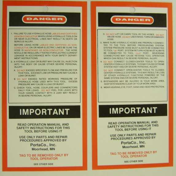
7 -Release the trigger and allow the tool to stop rotating. Press the button to reverse the rotation and check that the tool rotates in both directions. CAUTION: WHEN OPERATING THE TIE DRILL DO NOT CHANGE ROTATION WITH THE DRILL BIT ROTATING. ALLOW THE DRILL BIT TO COMPLETELY STOP ROTATING BEFORE PUSHING THE BUTTON. BE SURE TO FOLLOW ALL SAFETY GUIDELINES. 2.4 Hose Requirements It is not often necessary or advisable to use long hoses. All hoses must have an oil resistant inner surface and an abrasion resistant outer surface. Each hose must have male pipe ends for most application. Longer hoses can be used when necessary, but can affect the operation of the engine due to resistance in the hose. If small diameter or long hoses are used, or if restrictive fittings are connected to the supply and return ports, the pressure required to push the fluid through the system and back to the tank will be higher. This will reduce tool power. *Important Oil should always flow from the male coupler through the female coupler. NOTE: The pressure increase in uncoupled hoses left in the sun may make them difficult to connect. When possible after use, connect the free ends of the operating hoses together. HOSE TYPES Hydraulic hose types authorized for use by PortaCo, Inc. is as follows: 1. Labeled and certified nonconductive 2. Wire braided (conductive) 3. Fabric braided (not certified or labeled non-conductive) Hose 1: Listed above is the only hose authorized for use near electrical conductors. Hoses 2 and 3: Listed above are conductive and must never be used near electrical conductors. HOSE PRESSURE RATING The rated working pressure of the hydraulic hose must be at least 175 bar (2500 psi). 7
8 HYDRAULIC HOSE RECOMMENDATION Table 2.4 FLOW PER CIRCUIT LENGTH EACH HOSE USE INSIDE DIAMETER SAE SPEC HOSE (WIRE DRAID) SAE SPEC HOSE (FIBER BRAID) GPM LPM FEET METERS INCH MM 5 to 8 19 to 30 To 50 To 15 Both ½ 13 SAE 100R R7-8 5 to 8 19 to to 30 Both 5/8 16 SAE 100R2-10 SAE 100R to 8 19 to to 90 Pressure Return 5/8 ¾ SAE 100R2-10 SAE 100R1-12 SAE 100R8-10 SAE 100R to to 45 To 50 To 15 Both 5/8 16 SAE 100R2-10 SAE 100R to to to 30 Pressure Return 5/8 ¾ SAE 100R2-10 SAE 100R3-12 SAE 100R8-10 SAE 100R to to to 60 Pressure Return ¾ SAE 100R2-12 SAE 100R1-16 SAE 100R8-12 SAE 100R Hydraulic Fluid Recommendation The following fluids work well over a wide temperature range at startup, allow moisture to settle out, and resist biological growth likely in cool operating Hydraulic circuits. These fluids are Recommended by PortaCo Inc. Other That meets or exceeds the specifications of these fluids may also be used. Type Hydraulic fluid Chevron Clarity AW Exxon Univis J 32 Mobil D.T.E. 13 M Gulf Harmony AW-HVI Shell Tellus T 32 Texaco Rando HDZ 32 Union Unax AW-WR-32 Amsoil AWH Sunvis Low Pour H/032-product code Hydraulic fluid requirements: a) Viscosity (fluid Thickness) USA METRIC 50 F 4450 SSU Max 10 C 95 Centistokes 100 F SSU 38 C C.S. 140 F 85 SSU Min. 60 C 16.5 C.S, Min. Pour Point- 10 F/-23 C Minimum (for cold startup) Viscosity Index (ASTM D 2220) 140 Minimum Demulsibility (ASTM D-1401) 30 Minutes Maximum Flash Point (ASTM D-92) 340 F/171 C Minimum Rust Inhibition (ASTM D-665 A & B) Pass Oxidation (ASTM D943) 1000 Hours Minimum Pump Wear Test (ASTM D2882) 60 mg Maximum 2.6 Tool Connecting Procedures Stop the engine before connecting the tool and, or hoses to the off power unit, and when switching hoses or tools. Turn the hydraulic on/off valve to the off position before starting the engine. Make sure all hose are connected for correct flow direction to and from the tool being used. When routing hose in the work area, position them where personnel will not be at risk of tripping over them where vehicles can run over the hoses. Do not lay hose over sharp objects. WARNING: PRESSURIZED FLUID ESCAPING FROM A DAMAGED HOSE CAN PENETRATE THE SKIN AND BE INJECTED IN THE BODY CAUSING INJURY OR DEATH. CAUTION: DO NOT PULL ON HOSES TO DRAG POWER UNIT OR TOOL. 8
9 2.7 Work Area Safety Precautions - Never operate the tool when you are tired, angry, emotionally disturbed, or under the influence of alcohol, drugs, medications, or anything that could affect your vision, alertness, coordination or judgement. - Establish a training program for all operators to ensure safe operation. - Do no operate the tool unless thoroughly trained or under the supervision of an instructor. - Do not allow others to be near the tool when starting it or while operating. Keep bystanders and animals out of the work area. - Always wear safety goggles, ear, leg, and head protection devices, safety footwear, and snug fitting clothes. - Do not operate the tool near energized transmission lines. - Do not overreach. Maintain proper footing and balance at all times. - Always hold the tool with both hands, using a firm grip when activating and operating. - Be sure to keep hands and other body parts clear and free from all moving parts. - Always connect hydraulic hoses to the tool before activating the hydraulic circuit on your power unit. Check that hydraulic couplers are secure before activating the circuit. - Keep handles clean and dry. - Disconnect tool from hydraulic source before inspection or cleaning. - Only a properly trained person should perform any maintenance, service, and or repairs to a tool. - During start up of the tool, do not rest tool on any surface. - Make sure the tool s attachment was stopped turning before setting down tool. - At the work site, never carry the tool with the attachment rotating. - Always use attachements that meet the minimum requirements of the tool. - Never operate a tool that is damaged, improperly adjusted, or not completely and securely assembled. - Do not operate the tool until you have a clear work area and a secure balance. - Never carry or pick this tool up by the hydraulic hose. 9

10 SAFETY REGULATION Enter below any local or other safety regulations required for the operator to follow. Make sure the operator and maintenance personnel have knowledge of these regulations. 3.0 Operating Instructions 3.1 Description of Tool PortaCo s model DT-10-H3-O Tie Drill is designed to drill holes in wood railroad ties from a standing position. The drill reduces the risk to maintenance workers by eliminating the use of other methods which increase the likely hood of injury. When properly used it also reduces operator fatigue. The driver is equipped with a spool which reverses the drive direction. (Figure 3.1A arrow C) Insulated handles reduce vibration and operator fatigue. (Figure 3.1A arrow D) A grease zerk allows lubrication of the internal impact components without disassembling the tool. (Figure 3.1A arrow E) The Tie Drill requires a flow of 10 GPM (40 LPM) at 2000 PSI (138 Bar) for best performance. Use this tool on an open center hydraulic system only with a maximum pressure of 2150 PSI (148.3 BAR). D B C A The Tie Drill uses a 7/16 hex quick chuck to retain the drill bit. Only drill bits with a 7/16 hexagon shank are to be used with this drive system.(figure 3.1A Arrow F) F E PortaCo Inc s Tie Drill is operated from a T style handle. The handle features a trigger (Figure 3.1A arrow A) and trigger locking mechanism. (Figure 3.1A arrow B) Figure 3.1A PortaCo recommends the G-18D55-53W, a versatile power unit that can meet the needs for most hydraulic 10
 or one tool a 10 GPM (40 LPM) all the flows are at")
 and type RR 34-40 LPM (9-10.")

 The depth gauge attaches with two bolts at the impact head of the tool.")
11 tools used by the rail road industry. This power unit is capable of powering two tools simultaneously at 5 GPM (20 LPM) or one tool a 10 GPM (40 LPM) all the flows are at 138 BAR (2000 PSI). The maximum pressure of the hydraulic system is limited to BAR (2150 PSI). The power source provided the required flow and pressure to operated HTMA type I LPM (4-6 GPM) and type RR LPM (9-10.5) tools. All of which, are OPEN-CENTER tools required an operating pressure of 138 BAR (2000 PSI). A 3.2 Accessories and Kits Descriptions PortaCo, Inc. stocks a variety of drill bits to meet the customer s needs. B The tool can be fitted with a depth gauge, H OOK. (Figure 3.2A&B) The depth gauge attaches with two bolts at the impact head of the tool. If ordered with the Depth Gauge Kit, the kit is installed at the factory. The depth of the hole is set by loosening a clamping knob (Figure 3.2A Arrow A), adjusting the stop (Figure 3.2A Arrow B) to the desired position and then tightening the knob to lock it in position. Figure 3.2A Figure 3.2B 11

 (Figure 3.3D arrow A) protected and kept legible.")

12 3.3 Controls and Graphics The following decals are placed on the tool to aid in its operation and maintenance. The operator should locate and understand them before using this power tool. On the impact head there is a CAUTION decal that specifies that the Tie Drill is rated for a flow of 10 GPM/40 LPM and pressure of 2000 PSI/150 BAR do not exceed these flow / pressure ratings. Also on the decal is a few written warnings improper use may cause severe injury, read and understand operators manual before operating tool, keep all guards in place, during operation always wear gloves, safe clothing and footwear, and during operation always wear approved safety protection for ears, eyes, and head. (Figure 3.3A) (Figure 3.3D arrow A) protected and kept legible. The serial number is needed when ordering replacement parts. (Figure 3.3B) (Figure 3.3D arrow B) Figure 3.3B On the impact head there is a CAUTION decal that specifies to only use accessories which meet the requirements of the tool s rating. The decal also states the following: Do not exceed the tool s max. flow or pressure. Use on open-center system only. Correctly connect hoses to tool in and out ports. Improper handling, use, or maintenance of tool could result in a leak, burst, or other tool failure. Contact at a leak or burst can cause oil injection into the body. Failure to observe these precautions can result in serious personal injury. Read and understand the instructions in the operator s manual before using this tool. (Figure 3.3C) (Figure 3.3D arrow C) Figure 3.3A On the main body of the tool is a serial # decal. This decal has the serial number as well as the model number of the unit. Each unit has its own unique serial number. It is important to keep this decal Figure 3.3C 12


13 A B CAUTION: DO NOT PULL ON HOSES TO DRAG POWER UNIT. NOTE: When possible, connect the free ends of uncoupled hoses to prevent build up in the hoses. The sun can also increase pressure in the hoses and make connecting them difficult. 3.5 Tool Operation Position the drill bit in the location the hole is required. C Figure 3.3D 3.4 Connecting Hoses Wipe quick couplers with a clean lint free cloth before connecting them. 1. Connect hoses from power source to the tool. It is recommended that you connect the return hoses first and disconnect last to minimize or avoid trapping pressure within the tool. 2. When connecting the quick couplers, the flow should run from male coupler to the female coupler. The female coupler on the tool is the inlet. Quick couplers are marked with a flow direction arrow. WARNING: PRESSURIZED FLUID ESCAPING FROM A DAMAGED HOSE CAN PENETRATE THE SKIN AND BE INJECTED IN THE BODY CAUSING INJURY OR DEATH. Shift the spool to the direction of rotation desired. When holding the tool with the trigger in the right hand, pushing the spool towards the operator rotates the socket in the clockwise direction IN. Pushing the spool away from the operator rotates the socket counter clockwise OUT. (Figure 3.5A) Figure 3.5A CLOCKWISE COUNTER CLOSKWISE Caution: Do not shift the spool while the tool is operating, 13
14 damage to internal components may occur. Hold the tool securely with both hands, press the trigger lock down, and pull the trigger. To stop the drill, release the trigger. When the bit passes through the tie, continue to hold the trigger in the on position and carefully pull the dill up until the bit clears the hole. Release the trigger to stop rotation of the attachment. Running the tool while lifting it out of the hole will clean the hole. If using the depth stop, drill into the tie until the depth stop contacts the surface of the tie. Continue to hold the trigger in the on position and carefully pull the dill up until the bit clears the hole. Release the trigger to stop rotation of the attachment. Running the tool while lifting it out of the hole will clean the hole. If the drill bit binds in the hole and the tool can not be pulled out of the hole, release the trigger to stop the bits rotation. Change the rotation of the tool to OUT and pull the trigger while pulling the tool out of the hole. Push the rotation spool back to the IN position before going to the next hole. Move on the next hole to be drilled. 3.6 Disconnecting Hoses: 1. Stop the hydraulic power source. 3. Allow system and hydraulic fluid to cool. 4. Disconnect the supply (pressure) hose to the power source (pressure port) from the tool ( IN port). 5. Disconnect the return (tank) hose to the hydraulic power source (return port) from the tool ( OUT port). 6. To prevent contamination, always install dust caps over the hydraulic ports of the tool when disconnected. WARNING: IF INJURY RESULTS FROM ESCAPING HYDRAULIC FLUID, SEEK IMMEDIATE MEDICAL ATTENTION. SERIOUS BODILY INJURY MAY OCCUR IF PROPER MEDICAL ATTENTION IS NOT ADMINISTERED IMMEDIATELY. WARNING: DO NOT ATTEMPT TO LOCATE HYDRAULIC LEAKS BY FEELING AROUND HOSES AND FITTING WITH HANDS. PIN- HOLE LEAKS CAN PENETRATE THE SKIN. 3.7 Cold Weather Operation Hydraulic fluids are thicker in cold weather; therefore, run the engine at low idle lone enough to bring the fluid temperature up to minimum of 10 C/50 F or until the top of the hydraulic tank feels warm, before operating tool. 2. Depressurize the system 14
15 3.8 Storage Preparation Remove any installed drill bit or attachment. Cover male and female hose whips. Store in the upright position. Secure tool to prevent it from being knocked over. Store the Lag Driver on a smooth level surface or hung on a wall. The tool should be stored in a cool, dry environment which is not subjected to rapid temperature changes. 15
16 4.0 Maintenance Instructions CAUTION: USE ONLY GENUINE PORTACO INC. PARTS OR EQUIVALENT. THE USE OF REPACEMENT PARTS WHICH ARE NOT OF EQUIVALENT QUALITY MAY DAMAGE THE HYDRAULIC TOOL. 4.1 Assembly View and Parts List DT-10-H3-O Serial No. ITEM P/N DESCRIPTION QTY OSP NUT 1/4nc NYLOCK OOP LOCK WASHER ¼ OOP WASHER ¼ FLAT OOP FITTING 1/8 PLUG ALLEN OOP PLUG ¼ ALLEN OOP PLUT 3/8 ALLEN OOP BOLT 5/16nc X 1 SHCS OOP BOLT 1/4nc X 1-3/ OOP BOLT ¼nc X OOP VALVE FLOW OOD ORIFICE OOP PLUG 1/16 NPT ALLEN OOP BOLT 5/16 X 1-3/ OOP COUPLER HYD FEMALE OOP COUPLER HYD MALE OOP BOLT ¼ nc X ½ SHCS OOP BEARING OOD ORIFICE OOP WASHER LOCK 3/ OOP LINK VALVE # OOP SNAP RING ½ OOP BACK-UP OOP QUAD RING OOD TRIGGER SAFETY STOP OOD COUPLER SLINE OOD MANIFOLD CONTROL OOD SPOOL DIRECTIONAL OOD SPOOL ON/OFF OOD PLATE MOTOR ADAPTER OOP PIN ROLL.156 X OOP PIN RETAINER OOD HAND GRIP OOD GRAPHIC SET COMPLETE OOP SPRING TRIGGER STOP OOP FITTING SHORT OOP RING RETAINER OOP HEAD IMPACT OOW BRACKET MOUNT OOD LINK ON/OFF OOP HOSE WHIP OOW TRIGGER OOP MOTOR HYDRAULIC 1 16
17 ITEM P/N DESCRIPTION QTY OOP COVER DUST OOP BOLT 3/8 X 4-1/2 SHCS OOW HANDLE COMPLETE OOP ZERK GREASE 1/ OOP WIPER SEAL OOW SPOOL STOP OOP SCREW SET SOCKET ¼-20 X 3/ OOP BOLT #10-24 X ½ SHCS OOP WASHER LOCK # OOP SPRING OOW MOUNT CHUCK GUARD OOP ¾ DRIVE 7/16 QUICK CHUCK OOP COVER DUST OOW GUARD CHUCK OOP BOLT 1/4NC X OOP BOLT 3/8NC X ¾ SHCS OOP WASHER LOCK 5/
18 18
19 19
20 H OOK TIE DRILL DEPTH GAUGE ITEM P/N DESCRIPTION QTY OOW MOUNT GUIDE OOW GAUGE STOP OOD KNOB CLAMPING OOP NUT 5/ OOP WASHER LOCK 5/


21 4.2 Graphic Set Complete (3492-OOD) 2124-OOD 3492-O1D 2382-O9D 2158-OOD D 2158-O8D 3149-OOD 2158-O1D..CLEAR COAT FOR SERIAL NUMBER 21

22 4.3 Tool Maintenance Caution: All maintenance must be done with the tool disconnected form power source. CLEANING AND MAINTENANCE RECOMMENDATIONS. Wipe all external surfaces after each use with a clean, lint free cloth to remove surface contaminants from the tool. To extend the life of the handle padding, do not allow sharp edges or foreign objects to rub on the padding. Grease the impact mechanism using th grease zerk located on top of the motor adapter plate. (Figure 4.3A) Apply 2 to 3 strokes (approximately 4 cc s) from a standard grease gun using Mobil HP or equivalent grease. ZERK Store all tools in an enclosed area to prevent weather from contaminating their systems. Daily: 1. Wipe all tool surfaces, fittings, and couplings free of grease, dirt, and foreign materials. WARNING: DO NOT ATTEMPT TO LOCATE HYDRAULIC LEAKS BY FEELING AROUND HOSES AND FITTINGS WITH HANDS. PIN HOLES LEAKS CAN PENETRATE THE SKIN. 2. Inspect the tool, hydraulic system, hoses, and fittings for signs of leaks, cracks, wear, and/or damage. Replace if necessary. 3. To prevent contamination, always install dust caps over the hydraulic ports when disconnected. Weekly: FIGURE 4.3A Grease leakage from around the square drive is common after lubrication and during hard use. Wipe the grease off to prevent it from splattering. NOTE: Do not attempt to repair this product. Only properly trained personnel should perform any maintenance service, and or repair to this tool. Monthly: 1. Perform a detailed inspection of the systems hoses, and fittings according to the hydraulic hose operator s manual and as stated in SAE standard j1273, May 1989 or latest revision. Replace 22
23 the hoses and/or fittings if necessary. Semi-annually: Remove the impact head (item 37) and clean the grease off the impact components. Also remove the grease from the impact housing. Mount the impact head (item 37) to the motor adapter plate (item 29) after placing the assembled hammer mechanism in the impact head. After assembly, apply 100 strokes of grease (133 cc s) to the lubricating zerk. SERVICE COMPLETE DIASSEMBLY OF THE TOOL IS NOT RECOMMENDED. RETURN TO PORTACO, INC. FOR REPAIRS. 23
24 4.4 Trouble Shooting The following chart can be used as a guide to correct any problem you may experience with the tool. To determine the problem in operation of the Tie Drill always check that the hydraulic power source is supplying the correct hydraulic flow and pressure to the tool as listed in the table. Be sure you are using an accurate flow meter. Check the flow with the hydraulic fluid temperature at least 80 F/27 C. NOTE: Stop and depressurize the hydraulic system before connecting or disconnecting a tool. Failure to follow these instructions can lead to severe personal injury. Read and follow the instructions in this manual for the proper way to connect and disconnect tools from the hydraulic systems. PROBLEM CAUSE REMEDY Tool will not run or runs Power source slow. Poor impact performance. Coupler or Hose Directional spool not fully shifted. If after impact mechanism has been serviced. Mechanical failure Pressure and return hoses reversed Worn impact components Incorrect grease Cold hydraulic fluid Check power source flows and pressure (5-10 gpm/20-38 lpm at psi/ bar) Check for /remove obstruction Shift spool to either position. Check that all shims have been placed back between the impact head and adapter. Run impact to circulate grease. Disassemble tool and check for damage. Correct for proper flow direction. Disassemble front half of impact and check for damaged or severely worn parts. Remove and clean impact head (see maintenance section for procedures). Allow power source to warm up. 24
25 Trigger hard to pull Hydraulic fluid leaks between motor and manifold block. Hydraulic fluid leaks between adapter and motor. Hydraulic fluid leaks from control spools. Grease leaks between impact head and adapter. Grease leaks around impact drive shaft Grease leaks around impact drive shaft when cold. Back pressure too high Should not exceed 250 psi/ 17 Bar and 10 gpm/38 lpm Dirty spool Remove and clean spool and replace 0-rings and backups. Control linkage Inspect linkage between trigger and valve spool. Damaged seal Disassemble tool and replace seal. Damaged shaft seal Damaged seals Loose fasteners Heavy duty use. Impact mechanism over greased. Anvil bushing worn. Split tool between adapter and motor and replace seal. Replace all o-rings and backups on leaking spool. Tighten bolts. Normal due to heat build up. Wipe clean until grease stops leaking, adjust greasing maintenance to match duty cycle. Replace anvil bushing. NOTE: After reviewing trouble shooting chart and still unable to determine the problem call the service department at PortaCo inc. ( ) for advice 25
26 4.5 Technical Specifications MODEL Length Width Height Weight Max Pressure Max Flow DT-10-H3-O 4.50 in/11.4 cm in/8.3 cm in/45.7 cm 24.6-lbs/10.8 kg 2000 psi/150 bar 10 gpm/40 lpm Consumable Items List Description Part Number Source Coupler HYD FF-372-6FP M P PortaCo Inc. Coupler HYD FF-371-6FP F P PortaCo Inc. Cover Coupler # NR-37 BRUNNING P PortaCo Inc. Cover Coupler # NR P PortaCo Inc. 26
27 Hydraulic Fluid Requirements Viscosity (Fluid Thickness) METRIC U.S.A. 10 C 95 Centistokes 50 F 450 SSU Max 38 C C.S. 100 F SSU 60 C 16.5 C.S., Min. 140 F 85 SSU Min. Pour Point 10 F/-23 C Minimum (for cold startup) Viscosity Index (ASTM D 2220) 140 Minimum Demulsibility (ASTM D-1401) 30 Minutes Maximum Flash Point (ASTM D-92) 340 F/171 C Minimum Rust Inhibition (ASTM D-665 A & B) Pass Oxidation (ASTM D943) 1000 Hours Minimum Pump West Test (ASTM D2882) 60 mg Maximum Recommend Hydraulic Fluids Type Hydraulic fluid Chevron Clarity AW ISO 32 Exxon Univis J 32 Mobil D.T.E. 13 M Gulf Harmony AW-HVI Shell Tellus T 32 Texaco Rando HDZ 32 Union Unax AW-WR-32 Amsoil AWH ISO 32 Sunvis Low Pour H/032-product code Coupler recommendation: 3/8 inch FLAT FACE HTMA couplers rated at 2500 psi working pressure. Threads are to match fittings used on hoses or fittings used as adapters. Bolt Size #10-32 ¼-20 5/ /8-16 Torque 38 in. lbs. 76 in. lbs. 13 ft. lbs. 23 ft. lbs 27

28 DRILL BIT LIST If the drill required is not listed please call PortaCo, Inc and a service person will be able to assist your needs. 28
29 SERVICE AND REPAIR NOTES 29
MODEL DT-10-H3-O 3/4 TIE DRILL OPERATION AND MAINTENANCE MANUAL
 MODEL DT-10-H3-O 3/4 TIE DRILL OPERATION AND MAINTENANCE MANUAL 1 Warranty: PortaCo, Inc. warrants, to the original purchaser all products manufactured by it to be free from defects, in material and workmanship
MODEL DL-10-B1-O LAG DRIVER OPERATION AND MAINTENANCE MANUAL
 MODEL DL-10-B1-O LAG DRIVER OPERATION AND MAINTENANCE MANUAL 1 Warranty: PortaCo, Inc. warrants, to the original purchaser all products manufactured by it to be free from defects, in material and workmanship
LR O Safeloc Clip Remover MAINTENANCE MANUAL
 LR-05-81-O Safeloc Clip Remover MAINTENANCE MANUAL 1 TABLE OF CONTENTS 1.0 Introduction 1.1 General Information 1.2 Features 1.3 Options 1.4 Safety Summary 1.5 General Safety Precautions 1.6 Warning and
MODEL WS WELD SHEAR OPERATION, MAINTENANCE, AND REPAIR MANUAL
 MODEL WS-10-64-3 WELD SHEAR OPERATION, MAINTENANCE, AND REPAIR MANUAL 1805 2 nd AVENUE NORTH * MOORHEAD, MN, USA 56560-2310 PHONE (218) 236-0223 * FAX (218) 233-5281 E-MAIL ADDRESS; info@portaco.com *
MODEL WS WELD SHEAR HAND PUMP OPERATION, MAINTENANCE, AND REPAIR MANUAL
 MODEL WS-00-60- WELD SHEAR HAND PUMP OPERATION, MAINTENANCE, AND REPAIR MANUAL 805 nd AVENUE NORTH * MOORHEAD, MN, USA 56560-30 PHONE (8) 36-03 * FAX (8) 33-58 E-MAIL ADDRESS; info@portaco.com * INTERNET
MODEL GH GRINDER STRAIGHT HANDLE OPERATION, MAINTENANCE, AND REPAIR MANUAL
 MODEL GH-10-28-0 GRINDER STRAIGHT HANDLE OPERATION, MAINTENANCE, AND REPAIR MANUAL 1805 2 nd AVENUE NORTH * MOORHEAD, MN, USA 56560-2310 PHONE (218) 236-0223 * FAX (218) 233-5281 E-MAIL ADDRESS; info@portaco.com
MODEL CF-00-F3-O GAS FLANGE WAY CLEANER OPERATION, MAINTENANCE, AND REPAIR MANUAL
 MODEL CF-00-F3-O GAS FLANGE WAY CLEANER OPERATION, MAINTENANCE, AND REPAIR MANUAL 1805 2 nd AVENUE NORTH * MOORHEAD, MN, USA 56560-2310 1 PHONE (218) 236-0223 * FAX (218) 233-5281 E-MAIL ADDRESS; info@portaco.com
Hydraulic Power Unit Pioneer Series G-09, G-11, G-13
 Hydraulic Power Unit Pioneer Series G-09, G-11, G-13 OPERATION, MAINTENANCE, AND REPAIR MANUAL 1805 2 nd AVENUE NORTH * MOORHEAD, MN, USA 56560-2310 PHONE (218) 236-0223 * FAX (218) 233-5281 E-MAIL ADDRESS;
HYDRAULIC POWER UNIT PUP SERIES G-O5 OPERATION, MAINTENANCE, AND REPAIR MANUAL
 HYDRAULIC POWER UNIT PUP SERIES G-O5 OPERATION, MAINTENANCE, AND REPAIR MANUAL 805 2 nd AVENUE NORTH * MOORHEAD, MN, USA 56560-230 PHONE (28) 236-0223 * FAX (28) 233-528 E-MAIL ADDRESS; info@portaco.com
MODEL D-25S12-22-S POWER UNIT OPERATION, MAINTENANCE, AND REPAIR MANUAL
 MODEL D-25S12-22-S POWER UNIT OPERATION, MAINTENANCE, AND REPAIR MANUAL Introduction 1805 2 nd AVENUE NORTH * MOORHEAD, MN, USA 56560-2310 PHONE (218) 236-0223 * FAX (218) 233-5281 E-MAIL ADDRESS; info@portaco.com
Hydraulic Power Unit Prowler Series D-19
 Hydraulic Power Unit Prowler Series D-19 OPERATION, MAINTENANCE, AND REPAIR MANUAL 1805 2 nd AVENUE NORTH * MOORHEAD, MN, USA 56560-2310 PHONE (218) 236-0223 * FAX (218) 233-5281 E-MAIL ADDRESS; info@portaco.com
Hydraulic Power Unit Pioneer Series G-09, G-11, G-13
 Hydraulic Power Unit Pioneer Series G-09, G-11, G-13 OPERATION, MAINTENANCE, AND REPAIR MANUAL Original Instructions 2015 1805 2 nd AVENUE NORTH * MOORHEAD, MN, USA 56560-2310 PHONE (218) 236-0223 * FAX
Portable Hydraulic Power Pack
 USER'S GUIDE & SAFETY MANUAL USER'S GUIDE & SAFETY MANUAL Portable Hydraulic Power Pack Important Safety Notice Read and understand these usage and safety instructions before using a Condux Portable Hydraulic
P110 HYDRAULIC POWER UNIT USER S MANUAL SAFETY, OPERATION AND MAINTENANCE
 P110 HYDRAULIC POWER UNIT USER S MANUAL SAFETY, OPERATION AND MAINTENANCE 2017 ICS Blount Inc. 4909 SE International Way Portland, OR 97222 81117 9/2017 Ver. 1 NOTES 2 P110 User Manual 800.321.1240 icsdiamondtools.com
MODEL EGA200 OWNERS MANUAL
 3/8 RATCHET WRENCH MODEL EGA200 OWNERS MANUAL www.eaglecompressor.com 1-800-551-2406 READ THE ENTIRE MANUAL BEFORE PUTTING THIS TOOL IN SERVICE Limited Air Tool Warranty Wood Industries, Inc. warrants
Operator s Manual. Nitro 1000 Nitro 1000X. Nitro 750 Nitro 750X. September REV0
 Operator s Manual Nitro 750 Nitro 750X Nitro 1000 Nitro 1000X September.27.2018REV0 Table of Contents Introduction...3 Safety.....4 Equipment Requirements......5 What You Have Received. 5 Serial Number...6
HP12 HYDRAULIC POWER UNIT
 HP HYDRAULIC POWER UNIT (HPB) USER S MANUAL SAFETY, OPERATION AND MAINTENANCE 07 STANLEY Black & Decker, Inc. New Britain, CT 06053 U.S.A. 87 /07 Ver. TABLE OF CONTENTS SAFETY SYMBOLS... SAFETY PRECAUTIONS...5
HYDRAULIC TRASH PUMP. User s Manual TP03 SERIOUS INJURY OR DEATH COULD RESULT FROM THE IMPROPER REPAIR OR SERVICE OF THIS TOOL.
 User s Manual TP0 HYDRAULIC TRASH PUMP MODEL: TP0000, TP0000 SERIOUS INJURY OR DEATH COULD RESULT FROM THE IMPROPER REPAIR OR SERVICE OF THIS TOOL. c Copyright 200 The Stanley Works OPS USA & CE Version
MODEL EGA130 OWNERS MANUAL
 3/4 IMPACT WRENCH MODEL EGA130 OWNERS MANUAL www.eaglecompressor.com 1-800-551-2406 READ THE ENTIRE MANUAL BEFORE PUTTING THIS TOOL IN SERVICE Limited Air Tool Warranty Wood Industries, Inc. warrants air
DI-SP/TP. Operators Guide SUBMERSIBLE HYDRAULIC PUMPS HDI Inc. PO Box 1671 Gresham OR (FAX)
") DI-SP/TP SUBMERSIBLE HYDRAULIC PUMPS Operators Guide 2013 HDI Inc. PO Box 1671 Gresham OR 7030 206 274 4855 (FAX) SAFETY PRECAUTIONS INTRODUCTION Our hydraulically powered submersible dewatering and trash
DI-SP/TP SUBMERSIBLE HYDRAULIC PUMPS Operators Guide 2013 HDI Inc. PO Box 1671 Gresham OR 7030 206 274 4855 (FAX) SAFETY PRECAUTIONS INTRODUCTION Our hydraulically powered submersible dewatering and trash
SIP Direct Drive Oil-Lube Air Compressors - Operating & Maintenance Instructions
 SIP Direct Drive Oil-Lube Air Compressors - Operating & Maintenance Instructions Please read and fully understand the instructions in this manual before operation. Keep this manual safe for future reference.
Long Chassis Hydraulic Service Jacks
 Model BH6011 Long Chassis Hydraulic Service Jacks Operating Instructions and Parts Manual Capacity 10 Ton Model BH6011 U.S. Patent No's. 5,946,912 5,341,723! This is the safety alert symbol. It is used
Post Driver Attachment
 Attachment (Shown with Optional Power Cell Rotator) Models - 600, 850 Safety Instructions This safety alert symbol indicates important safety messages in this manual. When you see this symbol, carefully
MODEL EGA220 OWNERS MANUAL
 1/4 MINI RATCHET MODEL EGA220 OWNERS MANUAL www.eaglecompressor.com 1-800-551-2406 READ THE ENTIRE MANUAL BEFORE PUTTING THIS TOOL IN SERVICE Limited Air Tool Warranty Wood Industries, Inc. warrants air
HYDRAULIC CORE DRILL. Service Manual CD10 DANGER SERIOUS INJURY OR DEATH COULD RESULT FROM THE IMPROPER REPAIR OR SERVICE OF THIS TOOL.
 Service Manual HYDRAULIC CORE DRILL CD0 DANGER SERIOUS INJURY OR DEATH COULD RESULT FROM THE IMPROPER REPAIR OR SERVICE OF THIS TOOL. Copyright 2004 The Stanley Works OPS USA & CE Version 6544 6/2004 Ver.
GT23 HYDRAULIC POWER UNIT
 GT23 HYDRAULIC POWER UNIT SAFETY, OPERATION AND MAINTENANCE USER S MANUAL 2011 Stanley Black & Decker, Inc. New Britain, CT 06053 U.S.A. 69405 5/2013 Ver. 5 1 NOTES 2 TABLE OF CONTENTS SAFETY SYMBOLS...
STRAIGHT DIE GRINDER MODEL EGA530 OWNERS MANUAL
 STRAIGHT DIE GRINDER MODEL EGA530 OWNERS MANUAL www.eaglecompressor.com 1-800-551-2406 READ THE ENTIRE MANUAL BEFORE PUTTING THIS TOOL IN SERVICE Limited Air Tool Warranty Eagle warrants air tools of its
1/4 ANGLE DIE GRINDER
 1/4 ANGLE DIE GRINDER MODEL EGA500 OWNERS MANUAL www.eaglecompressor.com 1-800-551-2406 READ THE ENTIRE MANUAL BEFORE PUTTING THIS TOOL IN SERVICE Limited Air Tool Warranty Wood Industries, Inc. warrants
2000-LB. ENGINE STAND
 2000-LB. ENGINE STAND WARNING: Read carefully and understand all ASSEMBLY AND OPERATION INSTRUCTIONS before operating. Failure to follow the safety rules and other basic safety precautions may result in
ASSEMBLY and OPERATING INSTRUCTIONS Mission Oaks Blvd. / Camarillo, CA 93011
 SPARK PLUG CLEANER ASSEMBLY and OPERATING INSTRUCTIONS 3491 Mission Oaks Blvd. / Camarillo, CA 93011 Copyright 1997 by Harbor Freight Tools. All rights reserved. No portion of this manual or any artwork
1000-LB. ENGINE STAND
 1000-LB. ENGINE STAND WARNING: Read carefully and understand all ASSEMBLY AND OPERATION INSTRUCTIONS before operating. Failure to follow the safety rules and other basic safety precautions may result in
accidents which arise due to nonobservance and the safety information herein. SPECIFICATIONS
 22 TON LOG SPLITTER Model: 6212 CALIFORNIA PROPOSITION 65 WARNING: You can create dust when you cut, sand, drill or grind materials such as wood, paint, metal, concrete, cement, or other masonry. This
3 SUBMERSIBLE HYDRAPUMP INSTRUCTIONS
 3 SUBMERSIBLE HYDRAPUMP INSTRUCTIONS REIMANN & GEORGER CORPORATION CONSTRUCTION PRODUCTS BUFFALO, NY P/N 612---- 2/16/11 TABLE OF CONTENTS CHAPTER TITLE PAGE 1 SAFETY... 1 1.1 Introduction... 1 1.2 Safety
2000 lb Adjustable Gantry Crane
 2000 lb Adjustable Gantry Crane Owner s Manual WARNING: Read carefully and understand all ASSEMBLY AND OPERATION INSTRUCTIONS before operating. Failure to follow the safety rules and other basic safety
DIMENSIONS A- 27" B -20" C- 13"
 63 South 3rd Street P.O. Box 86 Paducah, KY 00 Phone: 70--0085 Fax:70-3-680 Website: www.matweld.com Email: customerservice@matweld.com 0500A WELD SHEAR The Matweld Weld Shear is lightweight and highly
1000 lb. Adjustable Gantry Crane
 1000 lb. Adjustable Gantry Crane Owner s Manual WARNING: Read carefully and understand all ASSEMBLY AND OPERATION INSTRUCTIONS before operating. Failure to follow the safety rules and other basic safety
2 TON CAPACITY PROFESSIONAL SERIES ALUMINUM JACK OWNER'S MANUAL SPECIFICATIONS
 80006 OWNER'S MANUAL CONTENTS: Page 1 Specifications 2 Warning Information 3 Setup, Operating and Preventative Maintenance 4 Troubleshooting 5 Maintenance 6 Exploded View Drawing and Replacement Parts
MG12K24T60V4 Mechanical Grapple
 170 State Route 271 Attachment Solutions MG12K24T60V4 Mechanical Grapple Operators Manual KENCO Mechanical Grapple Operation Manual 1 TABLE OF CONTENTS 170 State Route 271 Section I. General Information....
MODEL 5120 Tire Repair Station
 MODEL 5120 Tire Repair Station 00-0049 Installation, Operation & Repair Parts Information Branick Industries, Inc. 4245 Main Avenue P.O. Box 1937 Fargo, North Dakota 58103 REV01182017 P/N: 81-0058G CAUTION
MODEL 25-OM-10-C & 25-OA-10-C HYDRAULIC BOOSTER
 SPX Corporation 5885 11th Street Rockford, IL 61109-3699 USA Internet Address: http://www.powerteam.com Tech. Services: (800) 477-8326 Fax: (800) 765-8326 Order Entry: (800) 541-1418 Fax: (800) 288-7031
LUBRICATOR GUN INSTRUCTIONS-PARTS LIST. 10,000 psi (700 bar) Maximum Delivery Pressure. Detachable-type
 Maximum Delivery Pressure. Detachable-type") INSTRUCTIONS-PARTS LIST 306 460 INSTRUCTIONS This manual contains important warnings and information. READ AND KEEP FOR REFERENCE. Rev. E Supercedes D Detachable-type LUBRICATOR GUN 10,000 psi (700 bar)
INSTRUCTIONS-PARTS LIST 306 460 INSTRUCTIONS This manual contains important warnings and information. READ AND KEEP FOR REFERENCE. Rev. E Supercedes D Detachable-type LUBRICATOR GUN 10,000 psi (700 bar)
CONTENTS: SPECIFICATIONS 5712BT - 12 TON BENCH TOP HYDRAULIC SHOP PRESS OWNER'S MANUAL
 OWNER'S MANUAL CONTENTS: Page 1 Specifications 2 Warning Information 3 Assembly and Operating Instructions 4 Preventative Maintenance and Warranty Information 5 Exploded View Drawing and Parts List SPECIFICATIONS
Heavy Duty Engine Cranes
 Heavy Duty Engine Cranes Operating Instructions & Parts Manual Model Number Atd-7484 Atd-7485 (Foldable Legs) Capacity 2 Ton 2 Ton Model Atd-7484 Model Atd-7485 Atd Tools Inc. 160 Enterprise Drive, Wentzville,
Installation and Service Manual On-Highway Stabilization System
 An Actuant Company Installation and Service Manual On-Highway Stabilization System CONTENTS Part # 3010003373, REV 0E Section Page 1.0 Receiving Instructions 2 2.0 Safety Issues 2 3.0 Hydraulic Fluid 4
Pressure Roller with 24-inch Fixed Extension - For application of architectural paints and coatings -
 Instructions Important Safety Instructions Read all warnings and instructions in this manual. Save these instructions. 311082D Pressure Roller with 24-inch Fixed Extension - For application of architectural
6602LP CAPACITY: 2 TON LOW RIDER SERVICE JACK
 CONTENTS: Page 1 Specifications 2 Warning Information 3 Setup Instructions 4 Operating Instructions, Preventative Maintenance, Inspection and Proper Storage 5 Hydraulic Jack Maintenance Guide and Regular
Viscount I Hydraulic Motor and Displacement Pump
 INSTRUCTIONS-PARTS LIST 308 674 INSTRUCTIONS This manual contains important warnings and information. READ AND KEEP FOR REFERENCE. Rev. C Supersedes Rev. B Viscount I Hydraulic Motor and Displacement Pump
Single shot MODEL EGA700 OWNERS MANUAL
 Single shot AIR OPERATED GREASE GUN MODEL EGA700 OWNERS MANUAL www.eaglecompressor.com 1-800-551-2406 READ THE ENTIRE MANUAL BEFORE PUTTING THIS TOOL IN SERVICE Limited Air Tool Warranty Eagle warrants
4200 & 6200 Owner s Manual & Parts Book
 00 & 00 Owner s Manual & Parts Book Purchase Date Serial Number Model Number Tractor Model PN: - Dealer Date --0 Description Page To The Owner & Maintenance Safety Precautions & Torque Specifications Skid
Bucket Grease Pump ASSEMBLY AND OPERATING INSTRUCTIONS
 Bucket Grease Pump 9793 ASSEMBLY AND OPERATING INSTRUCTIONS 349 Mission Oaks Blvd., Camarillo, CA 930 Visit our Web site at http://www.harborfreight.com Copyright 2004 by Harbor Freight Tools. All rights
HPB45 and HPB55 Series Hydraulic Paving Breakers
 SERVICE MANUAL HPB45 and HPB55 Series Hydraulic Paving Breakers Serial Codes GMN, GMP, GMR, and GMT Read and understand all of the instructions and safety information in this manual before operating or
Lubricator Gun: 10,000 psi (700 bar) Maximum Delivery Pressure when disconnected from Dispenser
 Maximum Delivery Pressure when disconnected from Dispenser") INSTRUCTIONS-PARTS LIST 30 455 INSTRUCTIONS This manual contains important warnings and information. READ AND KEEP FOR REFERENCE. Rev. C Supercedes B Hand-Operated Portable Grease Dispenser Buckshot Luber
INSTRUCTIONS-PARTS LIST 30 455 INSTRUCTIONS This manual contains important warnings and information. READ AND KEEP FOR REFERENCE. Rev. C Supercedes B Hand-Operated Portable Grease Dispenser Buckshot Luber
Hydraulic Bead Breaker Kit
 Hydraulic Bead Breaker Kit Owner s Manual WARNING: Read carefully and understand all ASSEMBLY AND OPERATION INSTRUCTIONS before operating. Failure to follow the safety rules and other basic safety precautions
Trench Filler for Compact Utility Loaders
 Form No. 3353-608 Rev A Trench Filler for Compact Utility Loaders Model No. 22472 260000001 and Up Operator s Manual Register your product at www.toro.com Original Instructions (EN) Contents Page Introduction................................
GROUND ROD DRIVER 5/8 & 1 INSTRUCTIONS
 GROUND ROD DRIVER 5/8 & 1 INSTRUCTIONS RGC CONSTRUCTION PRODUCTS BUFFALO, NY P/N 6122235 07/29/08 TABLE OF CONTENTS CHAPTER TITLE PAGE 1 SAFETY...1 1.1 Introduction...1 1.2 Safety Definitions...1 1.3 Post
AG PRO SS Owner s Manual & Parts Book
 AG PRO SS Owner s Manual & Parts Book Purchase Date Serial Number Model Number Tractor Model Dealer PN: 63-19460 SN: 10204276-... Date 1-10-2017 Description Contents Page To The Owner, Maintenance, Safety
Hydraulic Immediate Need Power Pack
 Safety, Operation, and Maintenance Manual WARNING Improper use of this tool can result in serious bodily injury This manual contains important information about product function and safety. Please read
1300 Dozer Owner s Manual & Parts Book
 300 Dozer Owner s Manual & Parts Book Purchase Date Serial Number Model Number Tractor Model Dealer PN: 3-2472 0--2008 Contents Description Page To The Owner 2 Maintenance & Caution 2 Safety Precautions
P110 HYDRAULIC POWER UNIT
 P110 HYDRAULIC POWER UNIT Safety, Operation and Maintenance USER MANUAL Copyright 2012, ICS Blount, Inc. ICS Blount, Inc. 4909 SE International Way Portland, Oregon 97222 www.icsdiamondtools.com NOTES
HPB55 Series Hydraulic Paving Breaker
 INSTRUCTION MANUAL HPB55 Series Hydraulic Paving Breaker Serial Codes GMR and GMT Read and understand all of the instructions and safety information in this manual before operating or servicing this tool.
Read this entire manual before operation begins.
 Read this entire manual before operation begins. Record below the following information which is located on the serial number data plate. Serial No. Model No. Date of Installation Contents Specifications.............
SHOP PRESS ASSEMBLY INSTRUCTIONS
 SHOP PRESS ASSEMBLY INSTRUCTIONS 240AO - 40 Ton Air Over Shop Press PRESS SPECIFICATIONS Sunex Part No. A B C D E F G H 240AO 74.2" 32" 29.7" 12" 6.7" 1.2" Air Assist Y(2) A - Total Height B - Inside Width
Pressure Washer Hose Reel
 Pressure Washer Hose Reel Owner s Manual WARNING: Read carefully and understand all ASSEMBLY AND OPERATION INSTRUCTIONS before operating. Failure to follow the safety rules and other basic safety precautions
MODEL 7400 STRUT SPRING COMPRESSOR
 MODEL 7400 STRUT SPRING COMPRESSOR Installation, Operation & Repair Parts Information Branick Industries, Inc. 4245 Main Avenue P.O. Box 1937 Fargo, North Dakota 58103 REV112712 P/N: 81-0103A TABLE OF
Low Profile Service Jack
 Low Profile Service Jack Model GMG29031 Capacity 3 Ton U.S. Patent No. 6,199,379! This is the safety alert symbol. It is used to alert you to potential personal injury hazards. Obey all safety messages
Hydraulic PTO Flow Device
 Safety, Operation, and Maintenance Manual WARNING Improper use of this tool can result in serious bodily injury This manual contains important information about product function and safety. Please read
MODEL 7600 STRUT SPRING COMPRESSOR
 MODEL 7600 STRUT SPRING COMPRESSOR Installation, Operation & Repair Parts Information Branick Industries, Inc. 4245 Main Avenue P.O. Box 1937 Fargo, North Dakota 58103 REV6162014 P/N: 81-0246 TABLE OF
Garden Hose Reel with 3/4In. x 100Ft. Hose. Owner s Manual
 Garden Hose Reel with 3/4In. x 100Ft. Hose Owner s Manual WARNING: Read carefully and understand all ASSEMBLY AND OPERATION INSTRUCTIONS before operating. Failure to follow the safety rules and other basic
1000-LB. MOTORCYCLE LIFT TABLE OWNER S MANUAL
 1000-LB. MOTORCYCLE LIFT TABLE OWNER S MANUAL WARNING: Read carefully and understand all ASSEMBLY AND OPERATION INSTRUCTIONS before operating. Failure to follow the safety rules and other basic safety
Air-Operated 5:1 Oil Pump
 Air-Operated 5:1 Oil Pump With Extension Kit - 3.7 GPM Owner s Manual WARNING: Read carefully and understand all ASSEMBLY AND OPERATION INSTRUC- TIONS before operating. Failure to follow the safety rules
Mulcher Operators Manual
 Mulcher Operators Manual Skid Pro Attachments PO Box 982 Alexandria, MN 56308 October 2015 1 2 Contents 1. Introduction And Warranty... 4 1.1 Introduction... 4 1.2 Warranty... 4 2. Component Identification...
Fast Lift Service Jack, Low Profile
 Blackhawk Automotive is a Licensed Trade Mark Made by SFA Companies, Kansas City, MO Fast Lift Service Jack, Low Profile Operating Instructions & Parts Manual Model BH6023B Capacity 2 Ton! U.S. Patent
3-Pt. Quick Hitch. Owner s Manual
 3-Pt. Quick Hitch Owner s Manual WARNING: Read carefully and understand all ASSEMBLY AND OPERATION INSTRUCTIONS before operating. Failure to follow the safety rules and other basic safety precautions may
Operating Instructions & Parts Manual
 Swift Lift Hydraulic Service Jack Operating Instructions & Parts Manual Model Number ATD7341 Capacity 3-1/2 Ton U.S. Patent No's. 5,946,912 6,199,379! This is the safety alert symbol. It is used to alert
jegs.com. Installation Instructions for Ton Aluminum Floor Jack
 Installation Instructions for 80077 3-Ton Aluminum Floor Jack Contents: Specifications Warning Information Setup and Operating Instructions Preventive Maintenance and Troubleshooting Hydraulic Maintenance
OPERATING INSTRUCTIONS AND PARTS MANUAL
 Assembled in USA WARNING ATENCION ATTENTION OPERATING INSTRUCTIONS AND PARTS MANUAL 89143380-2 For technical assistance or the Dealer nearest you, call (360) 833-1600 8.914-338.0 2 CONTENTS Introduction...
Heavy-Duty Welding Fabrication Table
 Heavy-Duty Welding Fabrication Table with Fix-Up Kit Owner s Manual WARNING: Read carefully and understand all ASSEMBLY AND OPERATION INSTRUCTIONS before operating. Failure to follow the safety rules and
Adjustable Steel Welding Table
 Adjustable Steel Welding Table Owner s Manual WARNING: Read carefully and understand all ASSEMBLY AND OPERATION INSTRUCTIONS before operating. Failure to follow the safety rules and other basic safety
Hydraulic Drum Transporter
 Hydraulic Drum Transporter Owner s Manual WARNING: Read carefully and understand all ASSEMBLY AND OPERATION INSTRUCTIONS before operating. Failure to follow the safety rules and other basic safety precautions
Prime Attachments & Custom Fab Brush Mower Owners/Operators Manual
 Prime Attachments & Custom Fab Brush Mower Owners/Operators Manual The operator is responsible for the safe operation and maintenance of the machine. It is important that anyone who uses the machine is
GT23 HYDRAULIC POWER UNIT USER S MANUAL SAFETY, OPERATION AND MAINTENANCE
 GT23 HYDRAULIC POWER UNIT USER S MANUAL SAFETY, OPERATION AND MAINTENANCE 2014 STANLEY Black & Decker, Inc. New Britain, CT 06053 U.S.A. 69405 1/2018 Ver. 12 TABLE OF CONTENTS SAFETY SYMBOLS...4 SAFETY
Hydraulic Truck Jack
 Operating Instructions & Parts Manual Hydraulic Truck Jack Model Capacity 23221C 22 Ton 23222C (Low Profile) 22 Ton 23301 30 Ton Models 23221C & 23222C Model 23301! U.S. Patent No's. 5,341,723 & 5,94,912
TT-12 OWNERS MANUAL/PARTS LIST
 TOPLIFTER Tailgates By THIEMAN TT-12 OWNERS MANUAL/PARTS LIST SHOWN WITH OPTIONAL 2 PC. ALUMINUM PLATFORM! IMPORTANT! KEEP IN VEHICLE! PLEASE READ AND UNDERSTAND THE CONTENTS OF THIS MANUAL BEFORE OPERATING
Low Profile Service Jack Jack Stand Combo
 Low Profile Service Jack Jack Stand Combo Jack Stands Low Profile Service Jack U.S. Patent No. 6,199,379! This is the safety alert symbol. It is used to alert you to potential personal injury hazards.
4000 PSI Surface Cleaners
 4000 PSI Surface Cleaners Owner s Manual #49429 #49430 WARNING: Read carefully and understand all ASSEMBLY AND OPERATION INSTRUCTIONS before operating. Failure to follow the safety rules and other basic
MODEL D-100D1540-G9-O POWER UNIT OPERATION, MAINTENANCE, AND REPAIR MANUAL
 MODEL D-00D50-G9-O POWER UNIT OPERATION, MAINTENANCE, AND REPAIR MANUAL 805 nd AVENUE NORTH * MOORHEAD, MN, USA 56560-30 PHONE (8) 36-03 * FAX (8) 33-58 E-MAIL ADDRESS; info@portaco.com * INTERNET ADDRESS:
450 & Slant Top Owner s Manual & Parts Book
 0 & 0 - Slant Top Owner s Manual & Parts Book Purchase Date Serial Number Model Number Tractor Model PN: - Dealer Date -- Contents Description Page To The Owner & Maintenance Safety Precautions & Torque
600-lb. Trailer Dolly
 600-lb. Trailer Dolly Owner s Manual WARNING: Read carefully and understand all ASSEMBLY AND OPERATION INSTRUCTIONS before operating. Failure to follow the safety rules and other basic safety precautions
MODEL EF Full Circle Tire Spreader
 MODEL EF Full Circle Tire Spreader Installation, Operation & Repair Parts Information Branick Industries, Inc. 4245 Main Avenue P.O. Box 1937 Fargo, North Dakota 58103 REV. 062917 P/N: 81-0050C CAUTION
PENTECH, INC. BD Spray Gun. Operating Manual Parts Manual May, 2008 Issue 1. Plural Component, Impingement Mixing, Mechanical Purge Spray Gun
 PENTECH, INC. Operating Manual Parts Manual May, 2008 Issue 1 Plural Component, Impingement Mixing, Mechanical Purge Spray Gun BD Spray Gun PENTECH, INC. 7256 21 st Street East Sarasota, FL 34243 Phone:
Operating Instructions & Parts Manual. Air/Manual Hydraulic Bottle Jacks
 J18124-M1_032015 Operating Instructions & Parts Manual Air/Manual Hydraulic Bottle Jacks Model J18124 J18204 Capacity 12 Ton 20 Ton U.S. Patent Nos. 6,012,377-5,946,912! This is the safety alert symbol.
H Low Torque Impact Wrench
 SERVICE MANUAL H8508-3 Low Torque Impact Wrench Serial Code AKW Read and understand all of the instructions and safety information in this manual before operating or servicing this tool. Register this
FPC815 Pneumatic Rivet Tool
 WARRANTY If you have any problems with this tool, please call FPC Corporation toll-free at 1-800-860-3838 before returning it to the place of purchase. FPC815 Pneumatic Rivet Tool FPC Corporation warrants
Telescoping Pressure Washer Wand 18'
 Telescoping Pressure Washer Wand 18' Owner s Manual WARNING: Read carefully and understand all ASSEMBLY AND OPERATION INSTRUCTIONS before operating. Failure to follow the safety rules and other basic safety
OPERATIONS MANUAL LEVER CHAIN HOIST
 OPERATIONS MANUAL LEVER CHAIN HOIST IMPORTANT SAFETY INFORMATION Please read, understand and follow all safety information contained in these instructions prior to the use of this hoist. Retain these instructions
OWNER S MANUAL EVOLUTION 3500, 4500, 5500, & 8500 SERIES PUMPS
 OWNER S MANUAL EVOLUTION 3500, 4500, 5500, & 8500 SERIES PUMPS IMPORTANT SAFETY INSTRUCTIONS When installing and using this electrical equipment, basic safety precautions should always be followed, including
Push Trolley. Owner s Manual
 Push Trolley Owner s Manual WARNING: Read carefully and understand all ASSEMBLY AND OPERATION INSTRUCTIONS before operating. Failure to follow the safety rules and other basic safety precautions may result
TRAILER WINCH MODELS ST315 AND ST712. General Safety (Continued) Description. Unpacking. General Safety Information.
 Description. Unpacking. General Safety Information.") OPERATION AND MAINTENANCE MANUAL TRAILER WINCH READ CAREFULLY BEFORE ATTEMPTING TO ASSEMBLE, INSTALL, OPERATE OR MAINTAIN THE PRODUCT DESCRIBED. PROTECT YOURSELF AND OTHERS BY OBSERVING ALL SAFETY INFORMATION.
OPERATION AND MAINTENANCE MANUAL TRAILER WINCH READ CAREFULLY BEFORE ATTEMPTING TO ASSEMBLE, INSTALL, OPERATE OR MAINTAIN THE PRODUCT DESCRIBED. PROTECT YOURSELF AND OTHERS BY OBSERVING ALL SAFETY INFORMATION.
2 Speed Hydraulic Hand Pump
 Porto-Power Blackhawk Automotive is a licensed trademark 2 Speed Hydraulic Hand Pump Operating Instructions & Parts Manual B65122 B65421 SFA Companies 10939 N. Pomona Ave. Kansas City, MO 64153 816-891-6390
1732-M2 Portable C-Frame Punch Driver
 INSTRUCTION MANUAL GREENLEE 1732-M2 Portable C-Frame Punch Driver Read and understand all of the instructions and safety information in this manual before operating or servicing this tool. Register this