Patriot. Braking System. Owner s Manual
|
|
|
- Katrina Logan
- 6 years ago
- Views:
Transcription


1 Patriot Braking System Owner s Manual A new level of braking confidence. Patent Pending BRK2010 THANK YOU for purchasing a Patriot braking system from Blue Ox. We ve organized this manual to make your installation simple and as trouble-free as possible. Please read before operating the brake. Keep your sales receipt and this manual in a safe place so that both are available for future use if needed. Read and understand fully these instructions prior to the use of this product. Page 1 of Rev. B 7/8/10


2 Blue Ox One-Year Limited Warranty Automatic Equipment Manufacturing Company ( Automatic ) warrants to the original (first) retail purchaser this product, manufactured by Automatic, shall be free from defect in material and workmanship under normal use and service for a period of one year from the date of delivery. During said one-year period, Automatic will repair or replace any parts that have been returned by the original purchaser, to the factory, transportation prepaid, and in Automatics ti sole and absolute opinion found to be defective. Limitations on Warranty Coverage: Coverage under this warranty will be valid only if the customer warranty card is returned by the original purchaser within 30 days of purchase. Coverage under thiswarrantywillbeeffectiveonlywhenacopyoftheoriginalinvoice will effective when a copy of the original invoice, showingdate and place of purchase, accompanies companies any claim for warranty. This warranty is NON TRANSFERABLE. This limited warranty will not cover, in any way or form, any alleged damages caused by incorrect or improper p r installation, improper use, modification or neglect of product, failure to properly service and maintain, misuse, s act of God, accident or failure of the user to follow low guidelines ines contained in the instructional ional material al provided by Automatic. This warranty does not cover normal wear and tear, paint or rust. Warrantor assumes no responsibility i ity to the owner for loss of use of product, loss of time, inconvenience ce or any other damage consequential enti or otherwise. Including, ng, but not limited to mileage, expense of transporting of product, return rn shipping expense, mechanics cs travel time, telephone, e, road service, towing, and rental during repairs, travel, lodging, loss or damage to personal property or loss of earnings. ngs. REPAIR OR REPLACEMENT AS SET FORTH IN THIS LIMITED WARRANTY R IS THE SOLE EXCLUSIVE REMEDY OF THE PURCHASER. AUTOMATIC SHALL NOT BE LIABLE FOR ANY INCIDENTAL OR CONSEQUENTIAL NTIAL DAMAGES FOR BREACH OF ANY EXPRESS OR IMPLIED WARRANTY ON THIS PRODUCT. EXCEPT EPT TO THE EXTENT ENT PROHIBITED BY APPLICABLE LAW, ANY IMPLIED IED WARRANTY OF MERCHANTABILITY OR FITNESS FOR A PARTICULAR PURPOSE ON THIS PRODUCT IS LIMITED IN LENGTH TO THE DURATION OF THIS WARRANTY. Some states do NOT allow the exclusion of incidental of consequential damages, or allow limitations on how long an implied warranty lasts, so previous limitations or exclusions may NOT apply to you. This warranty gives you specific legal rights and you may also have other rights which vary from state to state. Automatic reserves the right to make changes or add improvements to its product at any time without any obligation to make such changes to previously manufactured equipment. No liability is assumed for bodily injury that may be inflicted on the purchaser, operator, spectator or general public who is in the general area while this equipment is in use. WARRANTY REQUEST PROCEDURE: If your Automatic product develops a defect during the warranty period, promptly notify Automatic Customer Care. Until such notice is received, Automatic will not be responsible for any repairs or replacement. Upon receipt of notice from you, Automatic will have a choice of options in repairing or replacing any part it determines in its sole and absolute desecration to be defective. 1.) Customer Care may require you, at your own expense, to deliver or ship the part to the factory for evaluation. They will issue a Return Merchandise Authorization (RMA) number if this is required. 2.) Any part that is, in Automatic s sole and absolute judgment, found to be defective in material or workmanship, will be repaired or replaced, at Automatic s option without charge for parts or labor. At Automatic s option, new, refurbished or improved parts may be used in the repair or replacement of warranted items or replacement products. Blue Ox Division Automatic Equipment Mfg. Co. P.O. Box 430 Pender, Nebraska (402) Page 3 of Rev. B 7/8/10

3 Product Information & Table of Contents Equipment Information Record Customer Name: Date Purchased: Purchased From: Address: City: State: Zip Code: Phone Number of Dealership: Installed By: Service #: Model #: Serial #: Notes:! WARNING -FOR YOUR SAFETY- Fully understand these instructions before installing. Improper installation and/or operation can create a hazard which can cause serious injury, property damage or death. Improper installation and/or operation will void the warranty. Table of Contents Page 2 Warranty Information Page 3 Equipment Information Record Table of Contents Customer Care Information Page 4 Welcome to the Blue Ox Experience Care and Maintenance Page 5 Unpacking Parts List Itemization Page 6 The Patriot Illustrated Pages 7-8 Installation Setup Page 9 & 10 Error Messages Pages11 Breakaway System Pages 12 Disconnecting Pages 13 Accessories At Blue Ox we pride ourselves in offering exceptional customer service to our valued customers. If you have any questions, comments, or concerns please feel free to contact a member of our Customer Care Team by calling (402) DEALERS AND DISTRIBUTORS: PLEASE give the instructions to the customer so they fully understand the setup, operation, and safety precautions of this braking system. Page 4 of Rev. B 7/8/10
4 Welcome to the Blue Ox Experience Congratulations! You are now the proud owner of a Patriot braking system. Welcome to the Blue Ox Family. The braking system that you have purchased combines quality components with the latest in technology and style. We are confident that these design features will provide you with the conveniences you expect during your travels. After you understand how to properly and safely operate and care for your Patriot, expect years of trouble-free operation and service backed by a one year limited warranty. In this manual, you will find installation instructions. Please read all of the technical documents, warnings, cautions, tips, and notes in this manual before attempting to operate your Patriot for the first time. Improper installation, use or maintenance may result in malfunction causing personal injury or property damage. Finally, don t forget to fill out and return your warranty card or registering via our web site at within ten days of delivery date and upon the original serial number being visible on the product and unaltered. For future reference, your serial number is located on the outside of the manual packaging and is also located on the bottom of your Patriot unit.! WARNING Do NOT modify your Patriot in any way NOT authorized by Blue Ox, as it will void the warranty. - REMINDER - Proper installation and use of this product is the sole responsibility of the purchaser. Care & Maintenance Care and Maintenance of your Patriot Braking System Your Patriot unit requires a minimal amount of care and maintenance. If you do not feel confident in your ability to perform the occasional maintenance, consult your Blue Ox Dealer or Professional Installer, or see a Blue Ox representative at a rally or race that you plan to attend. The following will inform you of the areas of your Patriot that will need periodic inspection and/or care and maintenance. - REMINDER - The maximum current that can be drawn from the cigarette lighter socket mounted on the Patriot is 2 amps. Care Do NOT use any type of solvent or spray cleaner on the Patriot braking system. The recommended cleaning procedures for the Patriot are to wipe down the exterior with a damp cloth. Wipe down with a dry cloth. Store in a clean, dry place. Maintenance It may be necessary to occasionally lubricate the brake bracket with silicone spray.! WARNING - USE ONLY GENUINE FACTORY REPLACEMENT PARTS - Do NOT substitute homemade or non-typical parts. This may cause your brake to fail and result in injury or death. If repair parts or components are needed, you may order them through your nearest Blue Ox Dealer or Distributor, or call our Customer Care Team at (402) Page 5 of Rev. B 7/8/10


5 Unpacking your Patriot Remove the Patriot and accessories from the shipping carton, review parts list and diagram below. Make sure that you have the appropriate items shown below. If NOT, please contact a Blue Ox Dealer or Distributor, or call a member of the Customer Care Team at (402) to order replacement parts. Patriot Braking System The Patriot brake system is comprised of the Patriot (with brake bracket assembly). Patriot 1 Breakaway System Tools & Supplies Required Phillips Screwdriver Wire Ties Vise Grip Rubber Grommet Silicone Sealant Page 6 of Rev. B 7/8/10 Contents: 1 Patriot assembly 4 Breakaway Switch 2 2-Way RF In-Coach Controller 5 Breakaway Lanyard 3 Brake Feet 6 Breakaway Cable 7 Breakaway Extension! WARNING Be sure the breakaway cable is kept clear of the towbar, safety cables, electrical cord or any moving parts. 6 7
6 The Patriot Illustrated Carrying Handle Actuator Arm Information Display One-button Set-up Brake Claw Adjustable Push Pad On/Off Switch 12 Volt, 2 Amp (Max) Receptacle Manual Override Lever Actuator Arm When activated, extends to press the brake bracket against the towed vehicle s brake pedal. RF Remote Unit Page 7 of Rev. B 7/8/10

 Note: If using a breakaway, it must be connected before turning on the unit. 6. Plug in power cord to cigarette lighter. Be sure there is 12 volt power. Indicator light will glow. 7.")


7 Installation Setup This section will explain how to install the Patriot. Note: Prepare the car for towing. Attach the tow bar. In Towed Vehicle: 1. Open driver side door of towed vehicle, and push driver seat back as far as possible. 2. Place BRK 2010 Patriot on the floor. 3. Open Claw and place it on the brake pedal. (Fig. 1) causing the brake lights to be activated. If the seat can t be moved forward far enough, an arm extension is available. (see page 13) Note: If using a breakaway, it must be connected before turning on the unit. 6. Plug in power cord to cigarette lighter. Be sure there is 12 volt power. Indicator light will glow. 7. Turn on the power switch. (Fig. 2) Display will read initializing. 8. When the display reads Position Arm Then Press Setup, press the JOG switch to push slightly on the brake pedal. (Fig. 3) The brake pedal should be depressed as far as possible WITHOUT activating the brake lights. Fig. 1 Place claw on brake pedal Note: The easiest way is to place the bottom of the claw under the pedal first, then slide the top of the claw over the top of the pedal. 4.The feet can be attached for proper height position. The rubber boots may be removed to expose the grippers on the feet. Note: Do not store or transport with the feet attached to the unit. 5. Slide the driver s seat forward to touch push pads. Adjust the push-pad up or down for proper height position in relation to the seat. Fig. 3 Adjust the brake pedal with the Jog Switch 9. Push the SETUP button. The brake will stroke 3 (three) times then remain in the ready position. Note: If the brake extends fully and remains extended without stroking three times, the seat is not far enough forward. Turn the brake off then back on. Reposition the seat as far forward as possible without causing the brake lights to be activated then continue with Step 8. Fig. 2 Turn on Power Switch Note: Seat must be as far forward as possible without Page 8 of Rev. B 7/8/10 Fig. 4 Push the Setup Button

8 Fig. 5 RF in-coach controller mounted on dashboard In the Motor Coach: Find a sturdy, easy-to-reach location to mount the RF in-coach controller. The dashboard is the suggested mounting point, but anywhere that is secure and accessible to the driver will work. Attaching the controller: Using the Velcro provided, attach one side to the desired mounting point, and the other side to the controller. Note: The Patriot Brake can be used with or without the RF controller. We recommend using the controller for the operational feedback, but the brake can be set without the RF controller. If your remote is not receiving a signal or to pair a new or unpaired remote module, perform the following steps: On the Remote: First, make sure the brake unit is plugged in and turned on. Hold down the Manual Override lever while plugging in the remote cord. Once the unit begins to light up, you can release the lever. An A will appear on the Remote LED screen indicating the unit is in Search Mode. Once the remote changes from an A on the LED to another character the remote is now paired and will remain so until this procedure is repeated. On the Brake Unit: Turn power to the brake unit off. Make sure the remote unit is plugged in. Firmly depress the BRK 2010 Patriot Operating Instructions 1. Plug the 2-Way RF In-Coach Controller into an available 12 volt outlet. 2. The large number on the display represents the sensitivity setting of the Patriot Brake; it will automatically be set to 5 when activated. 3. Turn the Gain knob to the left or right to adjust this setting. The lowest setting (0) puts the tow brake on stand-by and will apply no pressure to the brake. Settings 1 through 9 will incrementally increase the pressure applied. 4. On the bottom of the RF Controller there is a Manual Override Lever. Pressing down on this lever will cause the Patriot Brake to press down on the brake pedal. Note: This is a progressive lever; the lever controls the braking according to the level set on the RF controller. This acts like a trailer brake and is useful in wet weather to keep the towed vehicle in line. 5. If the error light turns on, Check the display screen on the Patriot Brake unit and refer to the list of possible display messages for assistance (see Fig. 6). After addressing the problem, turn off the Patriot Brake and restart the setup procedure. 6. If a breakaway switch is installed and plugged in, the BK / AWAY ON LED should be on. Follow the instructions provided. The break-away switch should be installed and plugged in before turning the brake on. 7. Anytime the towed vehicle is started up, the Patriot needs to be reset. 8. Go through the set up procedure again if the unit is shut off for any period of time and left in the toad or if the battery goes dead. JOG switch to the left AND simultaneously hold down the SETUP button while powering on the unit. Once the unit begins to light up you can release the buttons. The screen should read Remote Search and will only accept radio communication from the energized remote device. Once it finds the remote, it will automatically reset, and come up in normal operation mode. Each step should take approximately 10 seconds. Once a set is paired, go through the normal setup and make sure everything is functioning (make sure the Gain knob on the remote changes the gain displayed on the remote itself and also on the brake, and make sure that the Manual Override actually applies the brakes). Page 9 of Rev. B 7/8/10
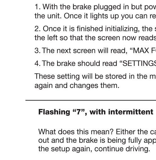
9 When installing the Patriot on hybrids, the settings menu must be accessed. To do this: 1. Hold down the setup button while turning the unit on, when it lights up let go of the button. 2. Once it is finished initializing, the screen will read MODE: FORCE. Hit the JOG switch to the left so that the screen now reads MODE: POSITION. Press SETUP to select this setting. 3. The next screen will read, MAX FORCE Press SETUP again at this screen. 4. The brake should read SETTINGS SAVED! and automatically restart. These setting will be stored in the memory and remain until a user goes through this procedure again and changes them. In a Hybrid vehicle, the GAIN setting should always be kept between settings 1 and 3. Error messages DO show up on the brake itself and NOT on the RF remote inside the RV. You are notified of an error on the RF, but the error messages are displayed on the brake. In order for the breakaway switch to work properly, it must be plugged into the brake before you turn the brake on. The following chart has details of the error messages in the Patriot. Each error has a corresponding code number that will show up in the remote. In Fig. 6 below, the first five rows and Flashing A are not errors, just the codes that will show up during normal use. LED Numeric Display Indication Description Non-flashing 0 through 9 Control Unit in READY state (normal operation), indicates current braking gain setting. Flashing 0 or A Control Unit in RADIO SEARCH state (looking for Remote Unit radio transmission to store MAC address). Flashing 1 Control Unit in INITIALIZING state (retract actuator). Flashing 2 Control Unit in POSITION state (manual jog). Flashing 3 Control Unit in SETUP state (pump brake pedal 3 times). Flashing 4, with intermittent beep Control Unit in CAR BATTERY LOW state (retract actuator, no braking function except breakaway). Flashing 5, with intermittent beep Control Unit in UNIT NOT LEVEL state (not currently implemented). Flashing 6, with intermittent beep Control Unit in REPOSITION state. Flashing 7, with intermittent beep Control Unit in BREAKAWAY state (maximum braking applied). Flashing 8, with intermittent beep Control Unit in BRAKING TIMEOUT state (retract actuator, no braking function except breakaway). Flashing C, with intermittent beep Communications error (Remote Unit not receiving radio transmissions from Control Unit). Page 10 of Rev. B 7/8/10 This will address the issue of users repeatedly getting REPOSITION BRAKE error during setup. If a user gets the REPOSITION BRAKE error twice in a row while trying to set up their brake, then they should do the following: 1. With the brake plugged in but powered off, hold down the SETUP button while powering on the unit. Once it lights up you can release the setup button. 2. Once it is finished initializing, the screen will read MODE: FORCE. Hit the JOG switch to the left so that the screen now reads MODE: POSITION. Press SETUP to select this setting. 3. The next screen will read, MAX FORCE Press SETUP again at this screen. 4. The brake should read SETTINGS SAVED! and automatically restart. These setting will be stored in the memory and remain until a user goes through this procedure again and changes them. With these settings, the brake will work on ANY vehicle. For a traditional vehicle, the GAIN setting should be kept between settings 6 and 9. In a Hybrid vehicle, the GAIN setting should be kept between settings 1 and 3. Error Messages Fig. 6


10 Blue Ox Patriot Detailed Explanation of Error Codes Page 11 of Rev. B 7/8/10
11 Breakaway System Description of your product. The Breakaway system automatically activates the Patriot to apply the brakes on your towed vehicle in the event the motorhome separates from the towed vehicle. This type of emergency system is required by most states and provinces. Installation This section will explain how to install the Breakaway. Mounting the Break-Away Switch 1. With the pin facing the motor home, secure the breakaway switch onto the front of the towed vehicle in a sturdy location. This should be a convenient location which can be easily reached, and if possible, on the driver s side. Note: The break-away switch must be mounted directly on the towed vehicle and not to be installed on the tow bar or bracket. The surface must be strong enough to hold the break-away switch and allow for the pin to be pulled out cleanly. 2. Make certain that the switch is securely attached, and that the pin can be removed from the switch without any interference. Plug the cable into the break-away switch. 3. Install the Break-Away Switch using a bolt and lock nut. Do not use a self tapping screw. Connecting the Break-Away Switch to the Patriot Brake There are two different ways to attach the break-away device to the Patriot Brake. Use the method which is most convenient for you. Method 1: Through the firewall 1. Look for a preexisting hole in the firewall, if no hole exists, drill a ½ diameter hole. Insert grommet into hole. Note: Make sure not to damage any components on either side of the firewall while drilling. 2. Find a path for the cable through the engine compartment to the firewall. Use wire ties to secure the cable. Make sure to avoid any hot or moving engine parts. 3. Insert the cable into the grommet and pull the excess slack into the driver s compartment. Seal around and inside of the grommet with silicone sealant. 4. Plug the cable into the Patriot Brake. Note: When not in use, the cable can be tucked away. Method 2: Feeding the cable through the door/window 1) Find a path for the cable through the engine compartment to the rear of the hood/base of the windshield, on the driver s side. Use nylon ties to secure the cable so that it is avoiding any hot or moving engine parts. 2) Either roll down the window and thread the cable through, or open the door and thread the cable through. Make sure excess slack is safely coiled inside the driver s cockpit. Once the cable is through and connected, close the door/window. Page 12 of Rev. B 7/8/10
12 Disconnecting This section will provide disconnecting information about the Patriot. Perform these steps each time you remove the Patriot. 1. Turn off the Patriot. Unplug the Patriot s power cord from the 12-volt accessory outlet. 2. Adjust the driver s seat as far back as possible. 3. Unhook the brake bracket from the brake pedal. Unplug the Breakaway clips from the Patriot control panel (if applicable). 4. Lift the Patriot out of the vehicle.! CAUTION These settings are GENERAL GUIDELINES ONLY and may vary depending on conditions, driver and/or the vehicles involved in your particular towing situation.! CAUTION Shut off the unit and unplug the RF when you stop driving for the day. Don t leave the unit plugged in all night, it could drain your car battery. To satisfy FCC RF exposure requirements for mobile and base station transmission devices, a separation distance of 20 cm or more should be maintained between the antenna of this device and persons during operation. To ensure compliance, operation at closer than this distance is not recommended. The antenna(s) used for this transmitter must not be co-located or operating in conjunction with any other antenna or transmitter. This equipment has been tested and found to comply with the limits for a Class B digital device, pursuant to part 15 of the FCC Rules. These limits are designed to provide reasonable protection against harmful interference in a residential installation. This equipment generates, uses and can radiate radio frequency energy, and if not installed and used in accordance with the instructions, may cause harmful interference to radio communications. However, there is no guarantee that interference will not occur in a particular installation. If this equipment does cause harmful interference to radio or television reception, which can be determined by turning the equipment off and on, the user is encouraged to try to correct the interference by one or more of the following measures: Reorient or relocate the receiving antenna. Increase the separation between the equipment and receiver. Connect the equipment into an outlet on a circuit different from that to which the receiver is connected. Consult the dealer or an experienced radio/tv technician for help Page 13 of Rev. B 7/8/10
 385-3051 to order these parts.")


13 Patriot Accessories If you would like to order any of these accessory parts for your Patriot, please contact a Blue Ox Dealer or Distributor, or call a member of the Customer Care Team at (402) to order these parts. VW Brake Claw Brake Rod Extension 2 This claw is designed to be used with the Patriot primarily when it is installed in a Volkswagen where the top section of the claw does not fit around the support holding the brake pedal.. The part number is BRK2501. If the seat can t be moved forward far enough, this rod extension is available to be inserted between the brake claw and the actuator arm. Also if there is a low steering column/dashboard which touches and interferes with the brake, this extension can be used. The part number is BRK2502. Seat Stiffener The seat stiffener works with any drop in tow brake on the market. It provides a larger surface area on the seat for the brake system to push against. This means you get better, more responsive braking. If you continually get a reposition brake error this will help solve that problem. To install: Put a piece of Velcro on the brake s push pads and on the outside of the seat stiffener. The brake s push pads should line up and push against the outside of the pockets. The part number is BRK2503. Page 14 of Rev. B 7/8/10
 385-3051. Serial Number Customer Service Commitment Blue Ox is focused on providing exemplary customer service, as observed in our mission statement and guiding principles.")
14 Don t rely on overburdened brakes. Instead, rely on a complete braking system from the company synonymous with safe, reliable RVing. Blue Ox. To find the Blue Ox dealer nearest you, visit or call (402) Serial Number Customer Service Commitment Blue Ox is focused on providing exemplary customer service, as observed in our mission statement and guiding principles. In accordance with this objective, Blue Ox is proud to provide services such as repairs and general eral maintenance of Blue Ox products at over 150 RV Rallies. Look ok for our Destination America or Blue Ox service crews at the next rally or race that you attend. Blue Ox also offers educational al seminars at rallies lies and through our Parks and Resort teams. In addition, Blue Ox customers visiting our factory may take advantage age of free e use of the wellequipped ed Blue Ox RV park at no charge to you, our valued and appreciated customer Blue Ox Blue Ox One Mill Road, Industrial Park Pender, Nebraska Printed in the USA Phone: (402) Fax: (402) Page 16 of Rev. B 7/8/10

15 Please visit for the latest version of these installation instructions. Patriot Braking System Owner s Manual & Installation Instructions THANK YOU for purchasing a Patriot braking system from Blue Ox. We ve organized this manual to make your installation simple and as trouble-free as possible. Please read before operating the brake. Keep your sales receipt and this manual in a safe place so that both are available for future use if needed Rev E Page 1 of 12 9/21/15
16 Patriot Braking System Welcome to the Blue Ox Experience Congratulations! You are now the proud owner of a Patriot braking system. Welcome to the Blue Ox Family. The inertia based braking system that you have purchased combines quality components with the latest in technology and style. We are confident that these design features will provide you with the conveniences you expect during your travels. After you understand how to properly and safely operate and care for your Patriot, expect years of trouble-free operation and service backed by a two year limited warranty. Please read all of the technical documents, warnings, cautions, tips, and notes in this manual before attempting to operate your Patriot for the first time. Improper installation, use or maintenance may result in malfunction causing personal injury or property damage. Please fill out and return your warranty card or register via our web site at within ten days of delivery. For future reference, your serial number is located on the outside of the manual packaging and is also located on the bottom of your Patriot unit. Equipment Information Record Customer Name: Date Purchased: Purchased From: Address: City: State: Zip Code: Phone Number of Dealership: Installed By: Service #: Model #: Serial #: Notes:! WARNING Fully understand these instructions before installing. Improper installation and/or operation can create a hazard which can cause serious injury, property damage or death. Improper installation and/or operation will void the warranty.! WARNING Always follow the towing procedures in your vehicle s owners manual. Do NOT modify your Patriot in any way NOT authorized by Blue Ox, as it will void the warranty. DEALERS AND DISTRIBUTORS: PLEASE give these instructions to the customer so they fully understand the set-up, operation, and safety precautions of this braking system Rev E Page 2 of 12 9/21/15


 385-3051.")

17 Patriot Braking System Unpacking your Patriot Remove the Patriot and accessories from the shipping carton, review parts list and diagram below. Make sure that you have the appropriate items shown below. If NOT, please contact a Blue Ox Dealer or Distributor, or call a member of the Technical Service Team at (402) to order replacement parts. Please charge the Patriot at least 8 hours prior to using. 1 Contents: 1. Patriot Unit 2. 2-Way RF In-Coach Controller 3. Brake Feet 4. Breakaway Switch 5. Breakaway Lanyard 6. Breakaway Cable 7. XL Top Fangs Important: USE ONLY GENUINE FACTORY REPLACEMENT PARTS. Do NOT substitute homemade or non-typical parts. This may cause your brake to fail and result in injury or death. If repair parts or components are needed, you may order them through your nearest Blue Ox Dealer or Distributor, or call our Technical Service Team at (402) Safety & Compliance This equipment has been tested and found to comply with the limits for a Class B digital device, pursuant to part 15 of the FCC Rules. These limits are designed to provide reasonable protection against harmful interference in a residential installation. This equipment generates, uses and can radiate radio frequency energy, and if not installed and used in accordance with the instructions, may cause harmful interference to radio communications. However, there is no guarantee that interference will not occur in a particular installation. If this equipment does cause harmful interference to radio or television reception, which can be determined by turning the equipment off and on, the user is encouraged to try to correct the interference by one or more of the following measures: Reorient or relocate the receiving antenna. Increase the separation between the equipment and receiver. Connect the equipment into an outlet on a circuit different from that to which the receiver is connected. Consult the dealer or an experienced radio/tv technician for help To satisfy FCC RF exposure requirements for mobile and base station transmission devices, a separation distance of 20 cm or more should be maintained between the antenna of this device and persons during operation. To ensure compliance, operation at closer than this distance is not recommended. The antenna(s) used for this transmitter must not be co-located or operating in conjunction with any other antenna or transmitter Rev E Page 3 of 12 9/21/15


18 Patriot Braking System Jog Switch Information Display Carrying Handle One-button Set-up Actuator Arm Brake Claw Adjustable Push Pad Breakaway Port On/Off Switch 12 Volt Receptacle (2 Amp Max) Patriot Brake Unit RF Remote Unit Manual Override Rev E Page 4 of 12 9/21/15
 385-3051 to order these parts.")


19 Patriot Braking System Patriot Accessories If you would like to order any of these accessory parts for your Patriot, please contact a Blue Ox Dealer or Distributor, or call a member of the Technical Service Team at (402) to order these parts. BRK2503: The seat stiffener works with any drop in tow brake on the market. It provides a larger surface area on the seat for the brake system to push against. This means you get better, more responsive braking. BRK2502: If the driver seat does not move far enough forward to touch the back of the brake, this brake rod extension can be inserted between the brake claw and the actuator arm. This extender should also be used if there is a low steering column/dashboard which touches and interferes with the brake. BRK2506: In order to protect your Patriot while not in use and to keep all accessories together, a protective bag is available. Note: The feet must be removed to fit into the protective bag. BRK2505: There is one (1) breakaway switch included with your Patriot. An additional switch for a second vehicle can be purchased Rev E Page 5 of 12 9/21/15


 The display will show the current electronics version and settings.")
 The brake will stroke three (3) times then remain in the ready position.")
20 Patriot Braking System In Towed Vehicle Towed Vehicle Set-Up 1. Insure your Patriot is charged prior to installing, otherwise plug it into a 12v source and charge fully prior to installing. 2. Open the driver side door of the towed vehicle and push the driver seat back as far as possible. 3. Place the Patriot unit on the floor. 4. Open the brake claw and secure it on the brake pedal. (Figure 1). 5. The Patriot can be used with out the feet. If needed the feet can be attached and adjusted for proper height position for uneven floorboards. 6. Slide the driver seat forward against the push pads. Adjust the push pad up or down for proper height position in relationship to the seat. Note: The seat should not put pressure on the back of the brake unit. 7. Plug in the power cord into a constant 12 volt power source. The indicator light will glow. Note: If constant 12V source is not used the brake could experience a low battery error 8. Turn on the power switch. (Figure 2) The display will show the current electronics version and settings. Note: Make sure tow brake is in Hybrid mode for any continuous power assist brakes or hybrid vehicles. (see Page 9) 9. Check to make sure the tow vehicle is not running. Note: Any time the towed vehicle is started up, the brake needs to be reset. 10. Push the SET-UP button. (Figure 3) The brake will stroke three (3) times then remain in the ready position. Note: The brake will read Ready and display the current gain setting when setup correctly. If the brake does not say Ready, turn the unit off and on and try the setup again. In the Motor Coach Find a sturdy, easy-to-reach location to mount the RF in-coach controller. The dashboard is the suggested mounting point, but anywhere that is secure and accessible to the driver will work. Using the Velcro provided, attach one side to the desired mounting point, and the other side to the controller. Note: The Patriot Brake can be used with or without the RF controller. We recommend using the controller for the operational feedback, but the brake can be set without the RF controller. Figure 1 Figure 2 Figure 3 Figure Rev E Page 6 of 12 9/21/15
.")


21 Patriot Braking System Locking Brake Claw Operating Instructions To Open: 1. Place your thumb on top of the claw and place your pointer finger under the back ledge (right). Pinch your fingers together until the claw locks in place (left). To Close: 2. Position the claw onto the brake pedal. NOTE: You can adjust the size of the claw by changing where the top fangs are mounted or by switching out the top fangs for the XL fangs. 3. Press the button on top of the claw to close the claw or push the front button against the brake pedal. Caution: Make sure your fingers are not between the upper and lower half of the claw when you press the button. To Lock: 4. If the claw is open, you can turn the knob one quarter turn to the left to lock it open. If the claw is closed, you can turn the knob one quarter turn to the left to prevent it from locking open. If the claw is locked, turn the knob one quarter turn to the right to unlock it Rev E Page 7 of 12 9/21/15
22 Patriot Braking System Breakaway Installation The Breakaway system automatically activates the Patriot to apply the brakes on your towed vehicle in the event the motor home separates from the towed vehicle. This type of emergency system is required by most states and provinces. Mounting the Breakaway Switch 1. With the pin facing the motor home, secure the breakaway switch onto the front of the towed vehicle in a sturdy location. This should be a convenient location which can be easily reached, and if possible, on the driver side. Note: The breakaway switch must be mounted directly on the towed vehicle and not to be installed on the tow bar or bracket. The surface must be strong enough to hold the breakaway switch and allow for the pin to be pulled out cleanly. 2. Make certain that the switch is securely attached, and that the pin can be removed from the switch without any interference. Plug the cable into the breakaway switch. 3. Install the breakaway switch using a bolt and lock nut. Do not use a self tapping screw. Connecting the Breakaway Switch to the Patriot Brake There are two different ways to attach the break-away device to the Patriot Brake. Use the method which is most convenient for you. Method 1: Through the firewall 1. Look for a pre-existing hole in the firewall, if no hole exists, drill a ½ diameter hole. Insert a grommet into hole. Note: Make sure not to damage any components on either side of the firewall while drilling. 2. Find a path for the cable through the engine compartment to the firewall. Use wire ties to secure the cable. Make sure to avoid any hot or moving engine parts. 3. Insert the cable into the grommet and pull the excess slack into the driver s compartment. Seal around and inside of the grommet with silicone sealant. 4. Plug the cable into the Patriot Brake. Note: When not in use, the cable can be tucked away. Method 2: Feeding the cable through the door/window 1. Find a path for the cable through the engine compartment to the rear of the hood/base of the windshield, on the driver s side. Use nylon ties to secure the cable so that it is avoiding any hot or moving engine parts. 2. Either roll down the window and thread the cable through, or open the door and thread the cable through. Make sure excess slack is safely coiled inside the driver s cockpit. Once the cable is through and connected, close the door/window.! WARNING Be sure the breakaway cable is kept clear of the tow bar, safety cables, electrical cord or any moving parts Rev E Page 8 of 12 9/21/15
23 Patriot Braking System Installation Notes When installing the Patriot on hybrids/vehicles with continuous power assist brakes or if the user gets the REPOSITION BRAKE error twice in a row while trying to set-up their brake, then they should do the following: 1. With the brake plugged in but powered off, hold down the SET-UP button while powering on the unit. Once it lights up you can release the set-up button. 2. Once it is finished initializing, the screen will read MODE: FORCE. Hit the JOG switch to the left so that the screen now reads MODE: POSITION. Press SET-UP to select this setting. 3. The next screen will read, MAX FORCE. Press SET-UP again at this screen. 4. The brake should read SETTINGS SAVED! and automatically restart. These setting will be stored in the memory and remain until a user goes through this procedure again and changes them. With these settings, the brake will work on ANY vehicle. For a traditional vehicle, the GAIN setting should be kept between settings 4 and 7. In a hybrid vehicle, the GAIN setting should be kept between settings 1 and 3. Operating Instructions 1. Plug the 2-Way RF In-Coach Controller into an available 12 volt outlet. 2. The large number on the display represents the GAIN setting of the Patriot Brake; it will automatically be set to 5 when activated. 3. Turn the GAIN knob to the left or right to adjust this setting. 0 should only be used if you want the brake to activate in a breakaway event 1 may be used for lighter vehicles (under 3000 GVWR) behind a large motor home (more than 25K GVWR) 3 may be used for lighter vehicles (under 3000 GVWR) behind a smaller motor home (under than 25K GVWR) or a mid sized vehicle (under 4000 GVWR) behind a class A motor home 5 (standard setting) may be used for mid sized vehicles (under 5000 GVWR) behind a mid sized motor home 7 may be used for large vehicles (over 5000 GVWR) behind any size motor home 9 may be used if you are having great difficulty stopping the towed vehicle and should used if setting 7 or 8 is not applying enough braking pressure 4. On the bottom of the RF Controller there is a MANUAL OVERRIDE lever. Pressing down on this lever will cause the Patriot to press down on the brake pedal. Note: This is a progressive lever; the lever controls the braking according to the level set on the RF controller. This acts like a trailer brake and is useful in wet weather to keep the towed vehicle in line. 5. If the error light turns on, check the display screen on the Patriot unit and refer to the list of possible display messages for assistance. After addressing the problem, turn off the Patriot and restart the set-up procedure. 6. Insure the Patriot is plugged into a constant 12V power source. 7. If a breakaway switch is installed and plugged in, the BK / AWAY ON LED should be on. Follow the instructions provided. 8. Anytime the towed vehicle is started up, the Patriot needs to be reset. 9. Go through the set-up procedure again if the unit is shut off for any period of time or if the battery in the unit goes dead. Disconnecting Perform these steps each time you remove the Patriot. 1. Turn off the Patriot. Unplug the Patriot power cord from the 12-volt accessory outlet. 2. Adjust the driver s seat as far back as possible. 3. Unhook the brake bracket from the brake pedal. Unplug the breakaway clips from the Patriot control panel (if applicable). 4. Lift the Patriot out of the vehicle. CAUTION: Shut off the unit and unplug the RF when you stop driving for the day. Don t leave the unit plugged in all night, it could drain your car battery Rev E Page 9 of 12 9/21/15
24 Patriot Braking System Troubleshooting/Error Codes Issue: If your remote is not receiving a signal or to pair a new or unpaired remote module. On the Remote: First, make sure the brake unit is plugged in and turned on. Hold down the MANUAL OVERRIDE lever while plugging in the remote cord. Once the unit begins to light up, you can release the lever. A blinking A will appear on the Remote LED screen indicating the unit is in SEARCH MODE. Once the remote changes from a blinking A on the LED to another character the remote is now paired and will remain so until this procedure is repeated. On the Brake Unit: Turn power to the brake unit off. Make sure the remote unit is plugged in. Firmly depress the JOG switch to the left AND simultaneously hold down the SET-UP button while powering on the unit. Once the unit begins to light up you can release the buttons. The screen should read REMOTE SEARCH and will only accept radio communication from the energized remote device. Once the unit finds the remote the screen will read REMOTE FOUND. Then automatically reset and come up in normal operation mode. Each step should take approximately 10 seconds. Once a set is paired, go through the normal set-up and make sure everything is functioning. Note: Make sure the GAIN knob on the remote changes the gain displayed on the remote itself and also on the brake, and make sure that the Manual Override actually applies the brakes). Error Codes: Error messages DO NOT show up on the RF remote inside the RV but on the brake itself. You are notified of an error on the RF, but the error messages are displayed on the brake. The following chart has details of the error messages in the Patriot. Each error has a corresponding code number that will show up in the remote. Listed below are codes that will show up during normal operation. If a code appears that is not listed below, please contact a customer care representative at (402) for further assistance. LED Numeric Display Indication Description Non-flashing 0 through 9 Control Unit in READY state (normal operation), indicates current braking gain setting. Flashing 0 or A Control Unit in RADIO SEARCH state (looking for Remote Unit radio transmission to store MAC address). Flashing 1 Control Unit in INITIALIZING state (retract actuator). Flashing 2 Control Unit in POSITION state (manual jog). Flashing 3 Control Unit in SETUP state (pump brake pedal 3 times). Flashing 4, with intermittent beep Control Unit in CAR BATTERY LOW state (retract actuator, no braking function except breakaway). Flashing 5, with intermittent beep Control Unit in UNIT NOT LEVEL state (not currently implemented). Flashing 6, with intermittent beep Control Unit in REPOSITION state. Flashing 7, with intermittent beep Control Unit in BREAKAWAY state (maximum braking applied). Flashing 8, with intermittent beep Control Unit in BRAKING TIMEOUT state (retract actuator, no braking function except breakaway). Flashing C, with intermittent beep Communications error (Remote Unit not receiving radio transmissions from Control Unit) Rev E Page 10 of 12 9/21/15
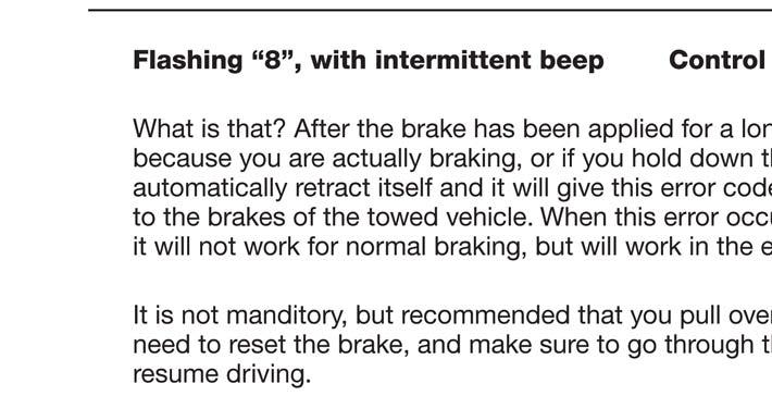
25 Error Code Explanations: Patriot Braking System FLASHING 4 WITH INTERMITTENT BEEP - UNIT IN CAR BATTERY LOW What does this mean? The car battery low error comes on when the brake reads an input voltage below 10V (unfiltered reading) or the unit battery is low. This means that the brake has detected that the towed car s battery is very low (OR the brake is no longer receiving power from the car receptacle) The brake will go into an idle state and not work for normal braking. It will work in the event of a breakaway! It is highly recommend, but not mandatory, that you pull over and inspect the towed vehicle. Check the indicator light on the power cord to see if the brake is receiving power. If this is the case, check the towed vehicles car battery voltage. Make sure to go through the set-up procedure again prior to resuming driving. Anytime the towed vehicle is started up, the Patriot needs to be reset. FLASHING 6 WITH INTERMITTENT BEEP - UNIT IN REPOSITION STATE What does this mean? If the user gets the reposition brake error two (2) times in a row while trying to set-up the brake, the following should be done: With the brake plugged in, but powered off, hold down the SET-UP button while powering on the unit. Once it lights up you can release the set-up button. Once it is finished initializing, the screen will read MODE: FORCE. Hit the JOG switch to the left so the screen reads MODE: POSITION. Press SET-UP to select this setting. The next screen will read MAX FORCE. Press SET-UP again at this screen. The brake should read SETTINGS SAVED! and automatically restart. These settings will be stored in memory and remain until the user goes through this procedure again and changes them. FLASHING 7 WITH INTERMITTENT BEEP - UNIT IN BREAKAWAY STATE What does this mean? Either the car actually did breakaway or the breakaway pin was pulled out and the brake is being fully applied. Pull over, secure the car, reset the brake, go through the set-up again and then continue driving. FLASHING 8 WITH INTERMITTENT BEEP - UNIT IN BRAKING TIME-OUT STATE What does this mean? After the brake has been applied for a long duration of time, whether it is due to actual braking or if you hold down the manual brake lever, the brake will automatically retract itself and it will give this error code. This is to prevent possible damage to the brakes of the towed vehicle. When this error occurs, the brake will go into an idle state and will not work for normal braking; however, it will work in the event of a breakaway! It is highly recommended that you pull over and check the towed vehicle. You will need to reset the brake. To change the SENSITIVITY of the brake: Hold down the SET UP button while powering on the unit. Once it lights up you can release the set up button. Once it is finished initializing, the screen will read MODE: FORCE, hit the SET UP button, the screen will read MAX FORCE, hit the SET UP button again and the screen will read SENSITIVITY three bars hit the Jog button to the left to lower the SENSITIVITY of the brake. Press the setup to select the setting. The brake should read SETTINGS SAVED and automatically restart. FLASHING C WITH INTERMITTENT BEEP - COMMUNICATIONS ERROR What does this mean? The 2 way RF in coach controller is no longer communicating with the Patriot Brake. The brake is still fully functional and should return to normal operation within a few seconds. This may be due to the position of the controller, if the problem persists contact Blue Ox customer care Rev E Page 11 of 12 9/21/15

26 Patriot Braking System Care and Maintenance of your Patriot Braking System Your Patriot unit requires a minimal amount of care and maintenance. If you do not feel confident in your ability to perform the occasional maintenance, consult your Blue Ox Dealer or Professional Installer, or see a Blue Ox representative at a rally or race that you plan to attend. The following will inform you of the areas of your Patriot that will need periodic inspection and/or care and maintenance. Care Do NOT use any type of solvent or spray cleaner on the Patriot braking system. The recommended cleaning procedures for the Patriot are to wipe down the exterior with a damp cloth. Wipe down with a dry cloth. Store in a clean, dry place. Maintenance It may be necessary to occasionally lubricate the brake bracket with silicone spray. Patriot units will need approximately 8 hours of charge time over a 3 month period. The car does not need to be on during this time. Also, the unit can be left plugged in for any period of time without causing damage. - REMINDER - The maximum current that can be drawn on the Patriot is 2 amps. Operating temperature of the Patriot is between -20ºF and 120ºF CUSTOMER SERVICE COMMITMENT Blue Ox is committed to providing you with exceptional customer care throughout your lifetime with our products. Our team is here to assist you with any questions you may have regarding the performance of your product. Simply call (402) and you can speak with our technical service team. Additionally, please visit our website to see which rallies our Destination America team will be attending. For a nominal fee, our service technician will service your towing system to ensure it s in proper working condition. Also, as a commitment to our customers, should you visit our factory, you can stay at our full service Blue Ox campground at no charge along with enjoying a factory tour. Again, thank you for being our customer and for the confidence you have shown in the performance of our products. It is because of customers like you we enjoy the success we have today Blue Ox One Mill Road, Industrial Park Pender, Nebraska Phone: (402) Fax: (402) Rev E Page 12 of 12 9/21/15
Patriot. Braking System. Owner s Manual
 Patriot Braking System Owner s Manual A new level of braking confidence. Patent Pending BRK2010 THANK YOU for purchasing a Patriot braking system from Blue Ox. We ve organized this manual to make your
Patriot II Braking System
 Please visit www.blueox.com for the latest version of these installation instructions. Owner s Manual & Installation Instructions THANK YOU for purchasing a Patriot II braking system from Blue Ox. We ve
Please visit for the latest version of these installation instructions.
 Please visit www.blueox.com for the latest version of these installation instructions. BX1730 Attachment Tab Height: 16 Serial Number Attachment Tab Width: 23 Please read BOTH these and the General Information
Please visit for the latest version of these installation instructions.
 Please visit www.blueox.com for the latest version of these installation instructions. BX1728 2017-18 GMC Acadia (Includes Denali & All-Terrain) (No Limited) Attachment Tab Height: 16 Serial Number Attachment
Please visit for the latest version of these installation instructions.
 Please visit www.blueox.com for the latest version of these installation instructions. BX2625 2011-15 Lincoln MKX (includes Adaptive Cruise Control) Attachment Tab Height: 18-1/4 Attachment Tab Width:
Please visit for the latest version of these installation instructions.
 Please visit www.blueox.com for the latest version of these installation instructions. BX2414 2019 Ram 1500 (Includes Rebel) (No Classic) Attachment Tab Height: 17 Serial Number Attachment Tab Width: 38.5
Please visit for the latest version of these installation instructions.
 Please visit www.blueox.com for the latest version of these installation instructions. BX3623 2017-19 Subaru Impreza (Manual) (No Fog Lights) Attachment Tab Height: 13 Serial Number Attachment Tab Width:
Please visit for the latest version of these installation instructions.
 Please visit www.blueox.com for the latest version of these installation instructions. Attachment Tab Height: 15-1/2 Serial Number Attachment Tab Width: 24 Please read BOTH these and the General Information
Please visit for the latest version of these installation instructions.
 Please visit www.blueox.com for the latest version of these installation instructions. BX2409 2009-18 Dodge Ram 1500 Sport/ST/Laramie Limited Please read BOTH these and the General Information sheet prior
Please visit for the latest version of these installation instructions.
 Please visit www.blueox.com for the latest version of these installation instructions. Attachment Tab Height: 18 Serial Number Attachment Tab Width: 18 Please read BOTH these and the General Information
Please visit for the latest version of these installation instructions.
 Please visit www.blueox.com for the latest version of these installation instructions. BX2265 Attachment Tab Height: 12.5 Serial Number Attachment Tab Width: 23 Please read BOTH these and the General Information
Please visit for the latest version of these installation instructions.
 Please visit www.blueox.com for the latest version of these installation instructions. BX2412 2016-18 Ram 1500 Rebel 2016-18 Ram 1500 Bighorn/Laramie/Laramie Longhorn (Chrome Bumpers) 2018 Ram 1500 (Metal
Please visit for the latest version of these installation instructions.
 Please visit www.blueox.com for the latest version of these installation instructions. Attachment Tab Height: 24-1/2 BX2675 (Incudes Super Duty & ACC) Serial Number Attachment Tab Width: 34-1/2 Please
BX Jeep Liberty Renegade 2012 Jeep Liberty Sport Installation Instructions
 Attachment Tab Height: 17.5 Attachment Tab Width: 24 Serial Number Please read BOTH these and the General Instructions prior to installing or operating this equipment. 1. Blue Ox towing products and accessories
Please visit for the latest version of these installation instructions.
 Please visit www.blueox.com for the latest version of these installation instructions. Attachment Tab Height: 19-1/2 Serial Number Attachment Tab Width: 19 Please read BOTH these and the General Information
Please visit for the latest version of these installation instructions.
 Please visit www.blueox.com for the latest version of these installation instructions. Attachment Tab Height: 16 Serial Number Attachment Tab Width: 35 Please read BOTH these and the General Information
Please visit for the latest version of these installation instructions.
 Please visit www.blueox.com for the latest version of these installation instructions. BX1126 Attachment Tab Height: 14-1/2 Serial Number Attachment Tab Width: 24 Please read BOTH these and the General
Please visit for the latest version of these installation instructions.
 Please visit www.blueox.com for the latest version of these installation instructions. 2014-2017 Ram 2500 (All beds) Please read these in their entirety prior to installing or operating this equipment.
Please visit for the latest version of these installation instructions.
 Please visit www.blueox.com for the latest version of these installation instructions. Attachment Tab Height: 21 Serial Number Attachment Tab Width: 31.25 Please read BOTH these and the General Information
Please visit for the latest version of these installation instructions.
 Please visit www.blueox.com for the latest version of these installation instructions. BX1986 Please read BOTH these and the General Information sheet prior to installing or operating this equipment. 1.
Please visit for the latest version of these installation instructions.
 Please visit www.blueox.com for the latest version of these installation instructions. Attachment Tab Height: 16.5 Serial Number Attachment Tab Width: 30.5 Please read BOTH these and the General Information
Please visit for the latest version of these installation instructions.
 Please visit www.blueox.com for the latest version of these installation instructions. BX1139 2018 Jeep Wrangler / Wrangler Unlimited (JL) (All Models w/standard Bumper) Attachment Tab Height: 18 Serial
BX7322 Adventurer Tow Bar Operator Manual & Installation Instructions
 Please visit www.blueox.com for the latest version of these installation instructions. BX7322 Operator Manual & Installation Instructions Serial Number (5,000 lb) 2 Inch Coupler 292-1263 Rev J Page 1 of
Please visit for the latest version of these installation instructions.
 Please visit www.blueox.com for the latest version of these installation instructions. BX1715 2014-15 Chevy Malibu (All Models) 2016 Chevy Malibu Limited (No Active Shutter or E-Assist) Attachment Tab
Please visit for the latest version of these installation instructions.
 Please visit www.blueox.com for the latest version of these installation instructions. BX1726 (All Models) (No Active Shutters or E-Assist) Attachment Tab Height: 12 Serial Number Attachment Tab Width:
Please visit for the latest version of these installation instructions.
 Please visit www.blueox.com for the latest version of these installation instructions. 2013-18 Ford C-Max (Includes Hybrid & Energi) Attachment Tab Height: 12 Serial Number Attachment Tab Width: 20 Please
Please visit for the latest version of these installation instructions.
 Please visit www.blueox.com for the latest version of these installation instructions. Attachment Tab Height: 17-1/2 Serial Number Attachment Tab Width: 24 Please read BOTH these and the General Information
Please visit for the latest version of these installation instructions.
 Please visit www.blueox.com for the latest version of these installation instructions. Attachment Tab Height: 25 Serial Number Attachment Tab Width: 22-1/2 Please read BOTH these and the General Information
BX7322 Adventurer Tow Bar Operator Manual & Installation Instructions
 Please visit www.blueox.com for the latest version of these installation instructions. BX7322 Operator Manual & Installation Instructions Serial Number (5,000 lb) 2 Inch Coupler 292-1263 Rev J Page 1 of
Please visit for the latest version of these installation instructions.
 Please visit www.blueox.com for the latest version of these installation instructions. BX3796 Attachment Tab Height: 13-1/2 Serial Number Attachment Tab Width: 24 Please read BOTH these and the General
Please visit for the latest version of these installation instructions.
 Please visit www.blueox.com for the latest version of these installation instructions. DH2400 (Long & Standard Box) Please read these in their entirety prior to installing or operating this equipment.
Please read BOTH these Installation Instructions and the General Information sheet prior to installing or operating this equipment.
 Attachment Tab Height: 24-1/4 Serial Number Attachment Tab Width: 24 Please read BOTH these and the General Information sheet prior to installing or operating this equipment. 1. Blue Ox towing products
Please visit for the latest version of these installation instructions.
 Please visit www.blueox.com for the latest version of these installation instructions. BX2643 Please read BOTH these and the General Instructions prior to installing or operating this equipment. 1. Blue
Please visit for the latest version of these installation instructions.
 Please visit www.blueox.com for the latest version of these installation instructions. BX1690 Attachment Tab Height: 16-1/2 Serial Number Attachment Tab Width: 18 Please read BOTH these and the General
Please visit for the latest version of these installation instructions.
 Please visit www.blueox.com for the latest version of these installation instructions. 2011-16 Mini Cooper Countryman (Includes S) Attachment Tab Height: 14 Serial Number Attachment Tab Width: 20 Please
Please visit for the latest version of these installation instructions.
 Please visit www.blueox.com for the latest version of these installation instructions. 2015-18 Ford Edge (Includes ACC) (No 2.0L EcoBoost or Sport) Attachment Tab Height: 15 Serial Number Attachment Tab
BX1681. Please read BOTH these Installation Instructions and the General Towing Instructions before attempting to install or operate this equipment.
 Serial Number BX1681 2007-13 Chevy Pickup 1500, 2500 & 3500 New Style Heavy Duty (2WD/4WD), 2007-11 GMC Pickup 2500 & 3500 New Style, 2008-10 GMC Yukon 2500 Please read BOTH these and the General Towing
Please visit for the latest version of these installation instructions.
 Please visit www.blueox.com for the latest version of these installation instructions. BX1718 2015-18 Chevy Suburban/Tahoe 2015-18 GMC Yukon/Yukon XL (Includes Denali) Please read BOTH these and the General
WARNING. Serial Number
 1999NS-2007 Chevrolet & GMC Pickup 1500 Classic (2WD & 4WD, No Heavy Duty) Please read BOTH these Installation Instructions and the Baseplate General Towing Instructions before attempting to install or
Please visit for the latest version of these installation instructions.
 Please visit www.blueox.com for the latest version of these installation instructions. 2012-17 Chevy Sonic (LS/LT/LTZ/RS) Attachment Tab Height: 13-1/2 Serial Number Attachment Tab Width: 18 Please read
Please visit for the latest version of these installation instructions.
 Please visit www.blueox.com for the latest version of these installation instructions. BX1689 Please read BOTH these and the General Information sheet prior to installing or operating this equipment. 1.
Please visit for the latest version of these installation instructions.
 Please visit www.blueox.com for the latest version of these installation instructions. BX2668 2016-19 Ford Explorer (Includes ACC, EcoBoost & Shutters) Attachment Tab Height: 16-1/2 Serial Number Attachment
CLASSIC II Portable Braking System
 39495 CLASSIC II Portable Braking System Inventor and Leader in Portable Technology! INSTRUCTIONS NEED HELP? CALL - 1-800-470-2287 (MONDAY - FRIDAY 8AM - 5PM CST) WARNING Read all instructions before installing
Please visit for the latest version of these installation instructions.
 Please visit www.blueox.com for the latest version of these installation instructions. BX1138 2014-18 Jeep Cherokee (No Trailhawk) (Includes Adaptive Cruise) Attachment Tab Height: 19-1/2 Serial Number
WARNING. BX Buick Lacrosse Installation Instructions. Bolt Torque Specifications. Bolt Torque Specifications
 Please read BOTH these and the General Instructions before attempting to install or operate this equipment. 1. Blue Ox towing products and accessories are intended to be installed by Blue Ox Dealers who
Please visit for the latest version of these installation instructions.
 Please visit www.blueox.com for the latest version of these installation instructions. Attachment Tab Height: 17-3/4 Attachment Tab Width: 18 Serial Number BX1708 2013-16 GMC Acadia (Includes Denali) 2017
Please visit for the latest version of these installation instructions.
 Please visit www.blueox.com for the latest version of these installation instructions. BX1307 2011-13 Mini Cooper Hardtop (Includes S) 2012-15 Mini Cooper Coupe (Includes S) 2009-15 Mini Cooper Convertible
BX7445 Aventa LX Tow Bar Operator Manual & Installation Instructions
 Please visit www.blueox.com for the latest version of these installation instructions. BX7445 Operator Manual & Installation Instructions Serial Number (10,000 lb) 2 Inch Receiver 292-2938 Rev D Page 1
BX4330 Acclaim Tow Bar Operator Manual & Installation Instructions
 Please visit www.blueox.com for the latest version of these installation instructions. BX4330 Operator Manual & Installation Instructions Serial Number (5,000 lb) 2 Inch Coupler 292-2205 Rev L Page 1 of
Please read BOTH these Installation Instructions and the General Towing Instructions before attempting to install or operate this equipment.
 Serial Number Please read BOTH these and the General Towing Instructions before attempting to install or operate this equipment. 1. Blue Ox towing products and accessories are intended to be installed
Please visit for the latest version of these installation instructions.
 Please visit www.blueox.com for the latest version of these installation instructions. 2016-18 VW Golf GTI Attachment Tab Height: 14 Serial Number Attachment Tab Width: 24 Please read BOTH these and the
Select II Portable Braking System
 39523 Select II Portable Braking System Inventor and Leader in Portable Technology! INSTRUCTIONS NEED HELP? CALL - 1-800-470-2287 (MONDAY - FRIDAY 8AM - 5PM CST) WARNING Read all instructions before installing
Please visit for the latest version of these installation instructions.
 Please visit www.blueox.com for the latest version of these installation instructions. Serial Number BX1721 2015-19 Chevy Colorado (4WD)(Includes Denali) 2015-19 GMC Canyon (4WD)(Includes Denali) Please
Please visit for the latest version of these installation instructions.
 Please visit www.blueox.com for the latest version of these installation instructions. 2011-15 Ford Explorer (Includes ACC & EcoBoost) Attachment Tab Height: 18-1/2 Serial Number Attachment Tab Width:
Please visit for the latest version of these installation instructions.
 Please visit www.blueox.com for the latest version of these installation instructions. BX3620 Please read BOTH these and the General Information prior to installing or operating this equipment. Serial
Please visit for the latest version of these installation instructions.
 Please visit www.blueox.com for the latest version of these installation instructions. Attachment Tab Height: 12 Serial Number Attachment Tab Width: 28 Please read BOTH these and the General Information
Please visit for the latest version of these installation instructions.
 Please visit www.blueox.com for the latest version of these installation instructions. 2016-2017 Chevy Silverado 1500 2016-2017 GMC Sierra 1500 (Includes Denali) Attachment Tab Height: 18 Serial Number
Please visit for the latest version of these installation instructions.
 Please visit www.blueox.com for the latest version of these installation instructions. BX2632 2011-15 Ford Explorer (Includes ACC & EcoBoost) Attachment Tab Height: 18-1/2 Serial Number Attachment Tab
TABLE OF CONTENTS. If you have any questions after reading these instructions, please call BrakeBuddy customer service at
 TABLE OF CONTENTS Congratulations on the purchase of your new BrakeBuddy! The BrakeBuddy was designed and built as an auxiliary braking system to operate in conjunction with the existing braking system
Please visit for the latest version of these installation instructions.
 Please visit www.blueox.com for the latest version of these installation instructions. BX2673 2015-2018 Ford Edge Sport (Includes ACC & Shutters) (No 2.0L EcoBoost) Please read BOTH these and the General
Please visit for the latest version of these installation instructions.
 Please visit www.blueox.com for the latest version of these installation instructions. BX3332 Attachment Tab Height: 21-1/2 Serial Number Attachment Tab Width: 18-1/2 Please read BOTH these and the General
SwayPro. Owner s Manual THANK YOU
 SwayPro Owner s Manual It s from Blue Ox. So you know it s built tough. BXW0551 550 lbs. maximum tongue weight capacity BXW0751 750 lbs. maximum tongue weight capacity BXW1001 1000 lbs. maximum tongue
Please visit for the latest version of these installation instructions.
 Please visit www.blueox.com for the latest version of these installation instructions. Attachment Tab Height: 18 BX1731 2016-2018 Chevy Silverado 1500 2016-2018 GMC Sierra 1500 (Includes Denali) 2016-2018
Please visit for the latest version of these installation instructions.
 Please visit www.blueox.com for the latest version of these installation instructions. BX1128 (Includes Trail Rated & Adaptive Cruise Control) Please read BOTH these and the General Instructions prior
SwayPro Owner s Manual & Installation Instructions
 SwayPro Owner s Manual & Installation Instructions Serial Number Underslung Hitch Head w/ Clamp-On Rotating Latches BXW0353 350 lbs. maximum tongue weight capacity BXW0553 550 lbs. maximum tongue weight
SwayPro. NOTE: A minimum tongue weight of 200 lbs. is required THANK YOU
 SwayPro Owner s Manual & Installation Instructions Serial Number Standard Hitch Head w/ Clamp-On Rotating Latches BXW0350 350 lbs. maximum tongue weight capacity BXW0550 550 lbs. maximum tongue weight
Please visit for the latest version of these installation instructions.
 Please visit www.blueox.com for the latest version of these installation instructions. Attachment Tab Height: 13-1/2 Serial Number Attachment Tab Width: 24 Please read BOTH these and the General Instructions
TC35160 & TC35270 Operation Manual & Installation Instructions
 Please visit www.blueox.com for the latest version of these installation instructions. TC35160 & TC35270 Operation Manual & Installation Instructions Serial Number Blue OX One Year Limited Warranty 292-6090
Please read BOTH these Installation Instructions and the General Instructions prior to installing or operating this equipment.
 2011-14 BMW Mini Cooper Countryman (Includes S) Attachment Tab Height: 14 Serial Number Attachment Tab Width: 20 Please read BOTH these and the General Instructions prior to installing or operating this
Please visit for the latest version of these installation instructions.
 Please visit www.blueox.com for the latest version of these installation instructions. BX2338 2012-17 Hyundai Accent GLS/SE (Includes Foglights) Attachment Tab Height: 14 Serial Number Attachment Tab Width:
Please read BOTH these Installation Instructions and the General Instructions prior to installing or operating this equipment.
 2011-15 BMW Mini Cooper Countryman (Includes S) Attachment Tab Height: 14 Serial Number Attachment Tab Width: 20 Please read BOTH these and the General Instructions prior to installing or operating this
BXR5203 RBW Li l Rocker & X-16 Curt E16 Installation Instructions. PinLock. Serial Number
 RBW Li l Rocker & X-16 Curt E16 Serial Number PinLock The act of uncoupling your fifth wheel trailer can be one of the most dangerous tasks performed when RVing. Accidents can cause broken bones, severed
Please visit for the latest version of these installation instructions.
 Please visit www.blueox.com for the latest version of these installation instructions. BX2410 Attachment Tab Height: 14 Serial Number Attachment Tab Width: 22 Please read BOTH these and the General Information
BX4330 Acclaim Tow Bar Operator Manual & Installation Instructions
 Operator Manual & Installation Instructions Serial Number (5,000 lb) 2 Inch Coupler 292-2205 Rev J Page 1 of 7 4/23/13 DO NOT INSTALL, OPERATE OR USE THIS EQUIPMENT UNTIL THE FOLLOWING OPERATING AND SAFETY
Please read BOTH these Installation Instructions and the General Instructions prior to installing or operating this equipment.
 Please read BOTH these and the General Instructions prior to installing or operating this equipment. 1. Blue Ox towing products and accessories are intended to be installed by Blue Ox Dealers who are familiar
ALPHA Tow Bar (6,500 lb) 2 Inch Receiver
 2 Inch Receiver") Operator Manual & Serial Number ALPHA Tow Bar (6,500 lb) 2 Inch Receiver 405-0154 Rev C Page 1 of 7 7/29/13 DO NOT INSTALL, OPERATE OR USE THIS EQUIPMENT UNTIL THE FOLLOWING OPERATING AND SAFETY INSTRUCTIONS
Operator Manual & Serial Number ALPHA Tow Bar (6,500 lb) 2 Inch Receiver 405-0154 Rev C Page 1 of 7 7/29/13 DO NOT INSTALL, OPERATE OR USE THIS EQUIPMENT UNTIL THE FOLLOWING OPERATING AND SAFETY INSTRUCTIONS
Please read BOTH these Installation Instructions and the General Instructions prior to installing or operating this equipment.
 2009-15 Dodge Ram 1500 Sport/ST/Laramie Limited Please read BOTH these and the General Instructions prior to installing or operating this equipment. 1. Blue Ox towing products and accessories are intended
Please read BOTH these Installation Instructions and the General Towing Instructions before attempting to install or operate this equipment.
 Please read BOTH these and the General Towing Instructions before attempting to install or operate this equipment. 1. Blue Ox towing products and accessories are intended to be installed by Blue Ox Dealers
BX1306. Please read BOTH these Installation Instructions and the General Towing Instructions before attempting to install or operate this equipment.
 Serial Number Please read BOTH these and the General Towing Instructions before attempting to install or operate this equipment. 1. Blue Ox towing products and accessories are intended to be installed
CAUTION. Even Brakes with a black cable need second vehicle kit Even Brakes with a blue cable need second vehicle kit 98450
 cable not included cable not included Even Brakes with a blue cable need second vehicle kit 98450 Even Brakes with a black cable need second vehicle kit 98400 Check the Even Brake serial number before
SwayPro. NOTE: A minimum tongue weight of 200 lbs. is required THANK YOU
 SwayPro Owner s Manual & Installation Instructions Serial Number Standard Hitch Head w/ Clamp-On Rotating Latches BXW0350 350 lbs. maximum tongue weight capacity BXW0550 550 lbs. maximum tongue weight
Please read BOTH these Installation Instructions and the General Towing Instructions before attempting to install or operate this equipment.
 Serial Number Please read BOTH these and the General Towing Instructions before attempting to install or operate this equipment. 1. Blue Ox towing products and accessories are intended to be installed
Please visit for the latest version of these installation instructions.
 Please visit www.blueox.com for the latest version of these installation instructions. Please read BOTH these and the General Information sheet prior to installing or operating this equipment. 1. Blue
Please read BOTH these Installation Instructions and the General Instructions before attempting to install or operate this equipment.
 Please read BOTH these and the General Instructions before attempting to install or operate this equipment. 1. Blue Ox towing products and accessories are intended to be installed by Blue Ox Dealers who
AC / 65 W M PLEASE READ BEFORE OPERATING THIS EQUIPMENT.
 AC / 65 W M 5V AX 11 PLEASE READ BEFORE OPERATING THIS EQUIPMENT. TABLE OF CONTENTS 1 2-10 6-8 11 11 12 14-15 AC / 65 W M 5V AX 11 Included Items Operating Instructions Troubleshooting Guide Maintenance
Please read BOTH these Installation Instructions and the General Towing Instructions before attempting to install or operate this equipment.
 Serial Number BX3773 2007-10 Toyota Scion TC Please read BOTH these and the General Towing Instructions before attempting to install or operate this equipment. 1. Blue Ox towing products and accessories
Please read BOTH these Installation Instructions and the General Instructions prior to installing or operating this equipment.
 Attachment Tab Height: 15-1/2 2002-09 Chevy Trailblazer / GMC Envoy 2004-07 Buick Rainier 2003-06 Isuzu Ascender 2002-04 Oldsmobile Bravada Serial Number Attachment Tab Width: 18 Please read BOTH these
WARNING. BX Dodge Durango Jeep Grand Cherokee (All Models)
") (Includes Trail Rated & Adaptive Cruise Control) Please read BOTH these and the General Instructions prior to installing or operating this equipment. 1. Blue Ox towing products and accessories are intended
(Includes Trail Rated & Adaptive Cruise Control) Please read BOTH these and the General Instructions prior to installing or operating this equipment. 1. Blue Ox towing products and accessories are intended
Please read BOTH these Installation Instructions and the General Towing Instructions before attempting to install or operate this equipment.
 Serial Number Please read BOTH these and the General Towing Instructions before attempting to install or operate this equipment. 1. Blue Ox towing products and accessories are intended to be installed
Installation Instructions
 patent pending Portable Proportional Braking System Installation Instructions Part number 9400 Towing and Suspension Solutions ROADMASTER, Inc. 6110 NE 127th Ave. Vancouver, WA 98682 800-669-9690 Fax 360-735-9300
BOLT TORQUE SPECIFICATIONS STANDARD BOLTS:
 10-05 TP2010,Rev. ASSEMBLY OPERATION REPLACEMENT PARTS Hyundai Accent BOLT TORQUE SPECIFICATIONS STANDARD BOLTS: METRIC BOLTS: Size Grade Torque Size Torque 5/16" 5 20 ft/lbs. 8mm 22 ft/lbs. /8" 5 5 ft/lbs.
WARNING. BX HUMMER H 2 Installation Instructions. Serial Number
 BX4102 Please read BOTH these and the General Towing Instructions before attempting to install or operate this equipment. Serial Number 1. Blue Ox towing products and accessories are intended to be installed
Please read BOTH these Installation Instructions and the General Towing Instructions before attempting to install or operate this equipment.
 Serial Number BX1303 Manual Transmission Only Please read BOTH these and the General Towing Instructions before attempting to install or operate this equipment. 1. Blue Ox towing products and accessories
Please read BOTH these Installation Instructions and the General Instructions prior to installing or operating this equipment.
 Attachment Tab Height: 25-1/2 Attachment Tab Width: 24 Serial Number Please read BOTH these and the General Instructions prior to installing or operating this equipment. 1. Blue Ox towing products and
BATTERY CHARGER INSTRUCTION MANUAL. model no. ACG112CL
 model no. ACG112CL BATTERY CHARGER IMPORTANT: Please read this manual carefully before running this battery charger and save it for reference INSTRUCTION MANUAL 3 TABLE OF CONTENTS Technical specifications
Please visit for the latest version of these installation instructions.
 Please visit www.blueox.com for the latest version of these installation instructions. BX3620 Please read BOTH these and the General Information prior to installing or operating this equipment. Serial
Please read BOTH these Installation Instructions and the General Towing Instructions before attempting to install or operate this equipment.
 Please read BOTH these and the General Towing Instructions before attempting to install or operate this equipment. 1. Blue Ox towing products and accessories are intended to be installed by Blue Ox Dealers
OPERATING INSTRUCTIONS
 OPERATING INSTRUCTIONS HALO BOLT 57720 Powerful, compact and easy to use, the HALO BOLT can safely jump start your car. In addition, you can use it to charge your phone, tablet or other electronic devices!