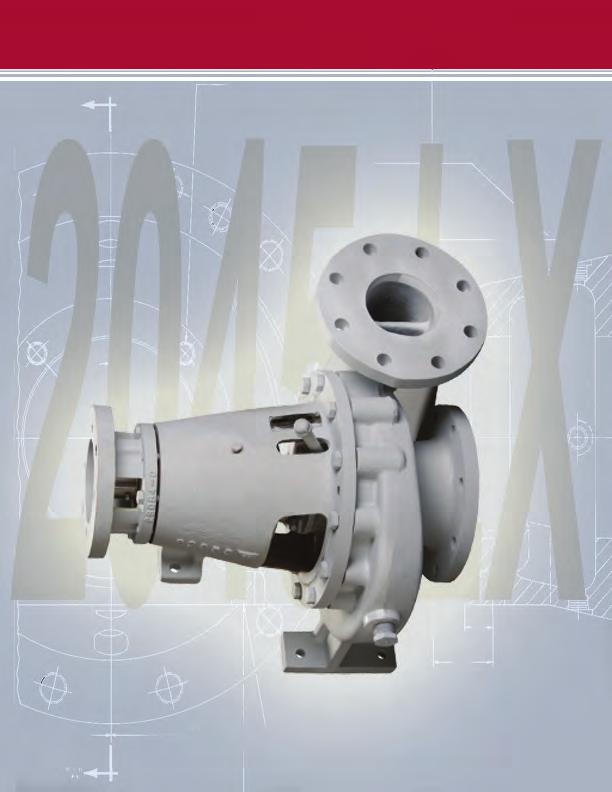
2045 LX Centrifugal Pump
|
|
|
- Harvey Willis
- 6 years ago
- Views:
Transcription
1


2 LX PUMP ASSEMBLY 1


3 DISASSEMBLY OF LX PUMP To disassemble pump, first remove nuts (12) where indicated around entire perimeter of pump housing. 2


4 DISASSEMBLY OF LX PUMP After (12) nuts are removed, entire rotating assembly may be pulled out of volute as shown above, using the push bolt holes as necessary. Note: Due to cement build up between Volute and pump housing it is sometimes difficult to remove rotating assembly. 3


5 DISASSEMBLY OF LX PUMP Remove Impeller retaining bolt. 4


6 DISASSEMBLY OF LX PUMP Use puller to remove impeller from shaft. 5

7 DISASSEMBLY OF LX PUMP Remove pipe nipple from stuffing box. 6


8 DISASSEMBLY OF LX PUMP After Impeller and pipe nipple are removed, remove Impeller key from shaft with proper tool being careful not to damage shaft. Note: This key is specific finish tolerances. Check for burrs, wear, nonconformance to shaft keyway. Replace if needed. 7
9 DISASSEMBLY OF LX PUMP Remove back head. 8


10 DISASSEMBLY OF LX PUMP Remove two bolts from Packing Gland. 9


11 DISASSEMBLY OF LX PUMP Remove packing gland (follower). This will give access to seals and lantern gland which may be removed from stuffing box at this time. Check all parts for wear. Caution: Take care when removing seals to prevent damage to seals and lantern gland. 10
12 DISASSEMBLY OF LX PUMP Before proceeding further with disassembly, remove this grease fitting. 11


13 DISASSEMBLY OF LX PUMP Remove Slinger locking screw. 12
14 DISASSEMBLY OF LX PUMP Remove slinger. 13


15 DISASSEMBLY OF LX PUMP Remove these bolts (4). Pick pump up and bump Impeller end of shaft against a heavy block of wood. This will remove shaft, bearings, and rear bearing retainer as an assembly. 14


16 DISASSEMBLY OF LX PUMP Rear bearing retainer, shaft and both bearings should slip out of the pump housing as an assembly. If the front bearing becomes disengaged from shaft and remains in the housing, it may be removed with the proper tooling. 15


17 DISASSEMBLY OF LX PUMP Remove internal snap ring from rear bearing retainer. 16


18 DISASSEMBLY OF LX PUMP Remove shaft and bearing(s) from rear bearing retainer. 17


19 DISASSEMBLY OF LX PUMP Remove nut and lock from rear of shaft. Bearing may be pressed off at this time. 18


20 DISASSEMBLY OF LX PUMP Remove rear seal. 19


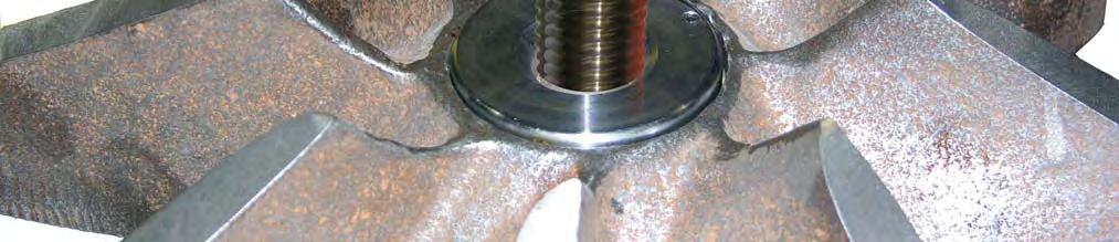
21 DISASSEMBLY OF LX PUMP Check this area inside shaft for wear. Hydraulic Motor Shaft Severe wear may occur to pump shaft at a point where splines of hydraulic motor contact shaft splines. Since it may not be possible to see this wear from the outside of shaft, the internal splines in shaft should be cleaned thoroughly with solvent and then inspected under a strong light. If the wear in this area exceeds.030, shaft should be discarded and no attempt to reuse or repair should be made. When splines become worn beyond the.030 limit, it becomes difficult and sometimes impossible to disengage hydraulic motor from pump shaft. If this occurs, the only solution is to cut motor shaft or splined end of pump shaft off with a torch. 20


22 ASSEMBLY OF LX PUMP Reassembly of pump should begin with the replacement of seal in rear bearing cover. Seal lip should face to the rear of housing away from rear bearing. This prevents any foreign material from entering rear bearing assembly. 21
 Install rear bearing and lock")
23 ASSEMBLY OF LX PUMP Lock Nut Rear Bearing (Outboard Bearing) Install rear bearing and lock nut. 22


24 ASSEMBLY OF LX PUMP Insert the shaft and rear bearing into bearing cover. 23
 bearing retaining ring. 24")
25 ASSEMBLY OF LX PUMP Install front (inboard) bearing snap ring. Install rear (outboard) bearing retaining ring. 24


")

26 ASSEMBLY OF LX PUMP Install front (inboard) bearing. 25


27 ASSEMBLY OF LX PUMP When shaft, bearings and rear bearing cover have been assembled, stand this assembly upright and install pump housing. 26


 at")
28 ASSEMBLY OF LX PUMP Bolt rear bearing cover to pump housing, but do not tighten bolts (qty. 4, P/N 17519) at this time. 27


29 ASSEMBLY OF LX PUMP Install slinger but do not tighten lock screw at this time. 28
 WITH THE.")

30 ASSEMBLY OF LX PUMP ANY PUMP THAT IS PACKED WITH THREE SEALS AND HAS THE PACKING GLAND (follower) WITH THE.625 DIMENSIONS INDICATED BY DOTTED LINES (LEFT) SHOULD BE MODIFIED TO THE.125 DIMENSION AND A 4 TH SEAL ADDED AS SHOWN ON PAGE
31 ASSEMBLY OF LX PUMP Modify as per Add one seal. Turn this seal around to position shown. Install seals (4) lantern gland and modified packing gland into stuffing box in backhead as indicated above. Note: Lubricate O.D. of seals before installation and observe placement of number (3) seal as the lip on this seal must face rear of pump. Item Req d Part. No. Description Gland, Packing Modified Gland, Lantern Oil Seal, Solid Packing 30

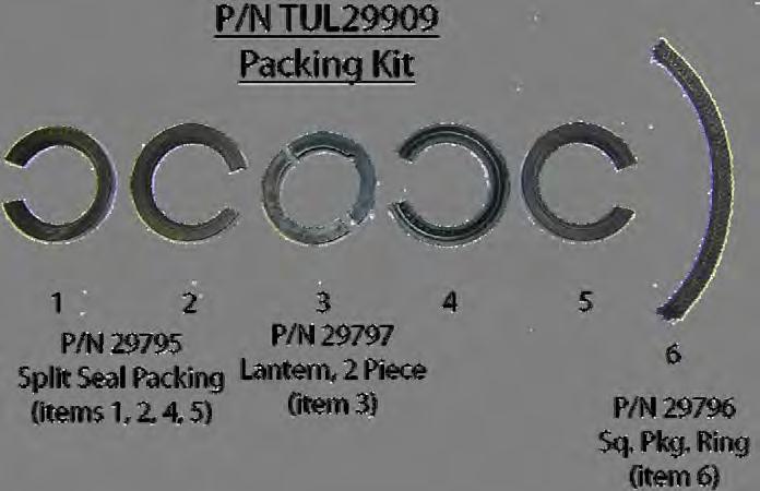
32 TYPICAL INSTALLATION OF CENTRIFUGAL PUMP PACKING TUL29909 I. REMOVE ALL WORN PACKING RINGS FROM THE STUFFING BOX AND CLEAN SAME THROUGHLY. 2. CHECK ALL BEARINGS PER THE MANUFACTURERS SPECIFICATIONS AND REPLACE SAME IF NECESSARY. CHECK THE SHAFT AND REPLACE IF NECESSARY. 3. LUBRICATE THE 2 PRIMARY SEAL RINGS. INSTALL AND SEAT EACH SEAL RING SEPARATELY, WITH ALL SEAL LIPS FACING TOWARD THE IMPELLER I STAGGERING THE SPLITS AT THE 12 O'CLOCK AND THE 3 O'CLOCK POSITIONS SO THAT THERE IS NO DIRECT LEAKAGE PATH ESTABLISHED. 4. LUBRICATE AND INSTALL THE 2 PIECE PLASTIC LANTERN RING. 5. LUBRICATE THE 2 SECONDARY SEAL RINGS. INSTALL AND SEAT EACH SEAL RING SEPARATELY AND AGAIN STAGGERING THE SPLITS AS FOLLOWS: (a) THE 1 ST SECONDARY SEAL RING OF THIS SERIES MUST BE INSTALLED WITH THE LIPS FACING AWAY FROM THE IMPELLER WITH SPLITS AT THE 6 O'CLOCK POSITION. THE REVERSE POSITION OF THIS SEAL WILL PREVENT AIR FROM BEING DRAWN THRU THE GLAND, AND THUS CAUSING THE LOSS OF PRIME. (b) THE 2 ND SECONDARY SEAL RING OF THIS SERIES MUST BE INSTALLED WITH THE SEAL LIPS FACING THE IMPELLER, AND WITH THE SPLIT AT THE 9 O'CLOCK POSITION. 7. LUBRICATE, INSTALL AND SEAT THE SPLIT COMPRESSION PACKING RING WITH THE SPLIT AT THE 12 O'CLOCK POSITION. 8. TO PROPERLY PRELOAD THIS COMBINATION SET, BOTTOM OUT THE FLAT SIDE OF THE GLAND AGAINST THE FACE OF THE STUFFING BOX. 31


33 ASSEMBLY OF LX PUMP 32


34 ASSEMBLY OF LX PUMP Install Packing in stuffing box area of backhead as directed on page
.")

35 ASSEMBLY OF LX PUMP Install Packing Gland (Follower). Install Packing gland bolts and tighten to 60 Nm ± 10 A light coating of chassis lube should be applied to the I.D. of seal assembly at this time. 34


36 ASSEMBLY OF LX PUMP Cover the seal area of the shaft with a light coating of chassis lube and install backhead gasket and O-ring. 35


37 ASSEMBLY OF LX PUMP Install backhead assembly as shown above using guide pin for proper alignment. Caution: Be extremely careful when the #3 seal contacts shaft as the lip on this seal points in the opposite direction of the other three (3) seals. and serious damage can result to seal lip or compression spring may become disengaged. 36

38 ASSEMBLY OF LX PUMP Install Impeller Key at this time. Caution: This Key is special and a standard Woodruff Key will not fit. 37


39 ASSEMBLY OF LX PUMP Install Impeller over shaft and key, being very careful that key does not become disengaged from shaft. 38


40 ASSEMBLY OF LX PUMP Install impeller lock and bolt as shown above and torque bolt to: 200 ± 15 lb. ft./280 ± 20 Nm Install set screw as shown above. 39


41 ASSEMBLY OF LX PUMP Entire rotating assembly may now be inserted into volute. Use mounting pedestals for proper alignment. Install housing nuts and torque to 150 ± 20 lb. ft.l200 ± 25 Nm. 40


42 ASSEMBLY OF LX PUMP Screw Lube pipe with cap into backhead. 41


43 ASSEMBLY OF LX PUMP Install grease zerk (P/N 17516). 42

44 IMPORTANT!!! THIS PROCEDURE MUST BE DONE FOR PUMP TO OPERATE TO DESIGN. For proper pump performance and long life, it is extremely important that these adjustments be made with care as this will assure the proper.030 clearance between the Impeller and Volute. Measure this distance Turn all adjusting screws counter clockwise until they are flush with front face of rear bearing retainer housing. Drive bearing retainer forward until Impeller contacts Volute. Turn adjusting screws clockwise until they contact pump housing. Turn each adjusting screw 1/4 turn. Continue in this manner until the initial distance plus.030 is reached. Torque retainer bolts to: 75 ± 10 lb. ft. / 100 ± 15 Nm Re-measure distance between pump housing and rear bearing retainer as it sometimes will change when retainer bolts are torqued. Some early pumps will have two (2) adjusting screws and two (2) retainer bolts while later models may have four (4) adjusting screws and four (4) retainer bolts. This does not affect adjusting procedure. 43


45 ASSEMBLY OF LX PUMP After pump has been installed and adjusted, adjust slinger toward rear of pump until it contacts front bearing and tighten lock screw. 44


46 ASSEMBLY OF LX PUMP After pump has been overhauled remove pipe plug in bottom of pump housing and install grease fitting. Remove pipe plug on side of housing. Pump NGL-1 or NGL-2 chassis lube into housing until it starts to come out of hole in side of housing where pipe plug was removed. While grease is being pumped into housing, pump should be turning as this will distribute lube to bearing and prevent over filling. 45
47 GARDNER DENVER DESIGN FEATURES GIVE LONG LIFE & EASY MAINTENANCE. The 2045 LX features two flow dividers resulting in three throats positioned 120 degrees apart which allows for a balance of thrust and forces and low radial loads, shortened flow path, development of full pressure at 1/3 revolution of impeller, distribution of wear at three points, prevention of air entrapment and vapor lock, reduction of shear and improvement of viscosity handling characteristics. The GD 2045 LX drive system has a mounting adapter bracket predrilled to accept a direct drive SAE C two, or four bolt hydraulic motor, and in conjunction with our internal splined shaft eliminates down time due to misalignment. Simplistic construction requires less assembly time and less spare parts inventory. The impeller design is fully open and ideally suited for handling fluids containing suspended solids. Impeller is available in an 8-vane pattern with a clockwise rotation. The frame is available in two versions, economical cast iron and steel fabricated. The GD 2045 LX offers two packing choices. Solid lip seals provide efficient service with a minimum amount of attention. Split compression type packing is available for more severe service conditions and can easily be replaced without dismantling the pump. Bearings provide maximum radial and thrust load capacity and are protected by a water slinger. 46


48 2045 LX Parts List Ref No. Name of Part Qty. Part No. Ref No. Name of Part Qty. Part No. 1 GASKET DISCHARGE BEARING LOCK NUT SET SCREW OIL SEAL, OUTBOARD IMPELLER BOLT (Hex Design) GASKET SUCTION IMPELLER LOCK WITH ROLL PIN VOLUTE LR 5 SPLIT LIP SEAL PACKING MODIFIED VOLUTE/NO PED A* RING ESTALS WITH EX DRAIN LR-SP 5A OIL SEAL SOLID PACKING 3 or PIPE PLUG LANTERN GLAND, 2 PIECE * 1/2 PIPE PLUG A LANTERN GLAND, SOLID GASKET, BACKHEAD SQUARE COMPRESSION PKG. RING IMPELLER, 8 VANE PACKING FOLLOWER, 2 PIECE 1 TUL O-RING BACKHEAD A PACKING FOLLOWER, SOLID BACKHEAD KEEPER LUBE PIPE WITH CAP HEX BOLT (Pkg. Follower/ 28 RETAINING SCREW, Backhead) SLINGER/SHAFT 11 BEARING, INBOARD SINGLE ROW 1 TUL SLINGER, 2 PIECE RETAINING RING, INBOARD FRAME, CAST 1 TUL IMPELLER KEY HEX BOLT, FRAME/VOLUTE SHAFT, INTERNAL SPLINED HEX BOLT, BEARING DRIVE COVER/FRAME GREASE ZERK THRUST AJUSTMENT SCREW RETAINING RING, OUTBOARD BEARING COVER & MOTOR BRACKET 17 BEARING, OUTBOARD Double row * These items not shown on this assembly drawing. 47
49 GARDNER DENVER PRODUCT WARRANTY GENERAL PROVISIONS AND LIMITATIONS Gardner Denver (the "Company") warrants to each original retail purchaser ("Purchaser") of its new products, assemblies or parts from the Company or its authorized distributors that such products are, at the time of delivery to the Purchaser, made with good material and workmanship. No warranty is made with respect to: 1. Any product which has been repaired or altered in such a way, in the Company's judgment, as to affect the product adversely. 2. Any product which has, in the Company's judgment, been subject to negligence, accident, or improper storage, improper installation, operation or application. (Examples: overpressure, sand-outs, cavitation, corrosion, erosion or degradation). 3. Any product which has not been operated or maintained in accordance with the recommendations of the Company. 4. Components or accessories manufactured, warranted and serviced by others. Any reconditioned or prior owned product. Claims for items described in (4) above should be submitted directly to the manufacturer. WARRANTY PERIOD The Company's obligation under this warranty is limited to repairing or, at its option, replacing, during normal business hours at an authorized service facility of the Company, any part or assembly which in the Company s judgment proved to have unsatisfactory material or workmanship within the applicable Warranty Period as follows. Except for the products or components listed below, and subject to the limitations and restrictions set forth in the Disclaimer section set forth below, the Warranty Period for all products is 1,250 hours of operation or three (3) months after start-up, not to exceed 120 days after delivery to Purchaser, whichever occurs first. The exceptions are as follows: 1. Power end is warranted for twelve (12) months from date of start-up or eighteen (18) months from date of delivery to the Purchaser, whichever occurs first. 2. Forged steel fluid cylinders are warranted for materials and workmanship for 6 months from the date of installation or 18 months from the date of delivery to the purchaser, which ever occurs first. 3. Repairs are warranted for 90 days from the date of delivery, for the workmanship and materials of the new parts installed. 4. Weld repaired fluid ends and weld repaired components are not warranted. 5. Expendable fluid end parts, including, but not limited to, valves, valve parts, packing, liners and pistons, are not covered by this warranty due to variable abrasive nature of material pumped. PRESERVATION ASSEMBLIES DESTINED FOR STORAGE In order for warranty acceptance any pump assembly not immediately installed or destined to be in storage or in transit for extended periods of time must be prepared for storage as defined in the Company s Long Term Storage Procedure. This includes but is not limited to: Drain and thoroughly clean inside power end crankcase. Spray rust inhibiting oil on all bearing, machined and inside surfaces of the power end. Induce clean gear oil into any circulating pump, filter, heat exchanger and piping. Remove valves, seats and plungers from the fluid end. Thoroughly clean and dry these parts and all internal surfaces. Coat all cylinder bores, valve covers and reusable expendable parts with rust preventative. Flush all water, and contaminants from pump, tanks, hoses and spray nozzles. Spray all components with a rust inhibiting oil. Rotate pump every 30 days to insure bearings are oiled. At the expense of the Purchaser, any product properly preserved must be inspected by an authorized agent of the Company, prior to the Company, granting any extended warranty beyond that stated in this warranty. LABOR TRANSPORTATION AND INSPECTION The Company will provide labor, by Company representative or authorized service personnel, for repair or replacement of any product or part thereof which in the Company's judgment is proved not to be as warranted. Labor shall be limited to the amount specified in the Company's labor rate schedule. Labor costs in excess 48
50 GARDNER DENVER PRODUCT WARRANTY of the Company rate schedules caused by, but not limited to, location or inaccessibility of the equipment, or labor provided by unauthorized service personnel is not provided for by this warranty. All costs of transportation of product or parts claimed not to be as warranted and, of repaired or replacement parts to or from such service facility shall be borne by the Purchaser. The Company may require the return of any part claimed not to be as warranted to one of its facilities as designated by the Company, transportation prepaid by the Purchaser, to establish a claim under this warranty. Replacement parts provided under the terms of this warranty are warranted for the remainder of the Warranty Period of the product upon which installed to the same extent as if such parts were original components. The Company may request a root cause analysis be performed in-order to identify if a request for warranty claim meets the requirements of this warranty. DISCLAIMER Except as to title, the foregoing warranty is the sole and exclusive warranty of the Company. The Company hereby extends other manufactures warranty or guaranties, if any given to Company by such manufacturer, but only to the extent the Company is able to enforce such warranty or guaranties. The Company has not authorized any party to make any representation or warranty other than as expressly set forth herein. SELLER HEREBY DISCLAIMS AND EXCLUDES ANY OTHER EXPRESS, IMPLIED OR STATUTORY WARRANTIES, ARISING BY OPERATION OF LAW OR OTHERWISE, INCLUDING, WITHOUT LIMITATION, ANY WARRANTIES OF MERCHANTABILITY OR FITNESS FOR A PARTICULAR PURPOSE. COMPANY MAKES NO WARRANTIES OR REPRESENTATIONS OF ANY KIND WHATSOEVER (EXPRESS, IMPLIED OR STATUTORY), OF LAW OR OTHERWISE, ON ANY EQUIPMENT, COMPONENT PARTS OR ACCESSORIES SOLD HEREUNDER WHICH, ARE NOT MANUFACTURED BY COMPANY. NOTWITHSTANDING ANYTHING HEREIN TO THE CONTRARY, THE FOREGOING WARRANTY SHALL BE THE SOLE AND EXCLUSIVE REMEDY AVAILABLE TO THE PURCHASER. UNDER NO CIRCUMSTANCES, WHETHER IN CONTRACT, TORT OR OTHERWISE, SHALL THE COMPANY S TOTAL LIABILITY ARISING IN CONNECTION WITH ANY PURCHASE ORDER EXCEED THE AMOUNT OF ANY SALES OR OTHER PROCEEDS RECEIVED PURSUANT THERETO. IN ADDITION, UNDER NO CIRCUMSTANCES, WHETHER IN CONTRACT, TORT OR OTHERWISE, SHALL THE COMPANY BE LIABLE FOR LIQUIDATED, SPECIAL, INDIRECT, INCIDENTAL, EXEMPLARY, OR CONSEQUENTIAL DAMAGES, EXPENSES OR COSTS, INCLUDING, WITHOUT LIMITATION, LOST PROFITS OR FACILITY DOWNTIME, HOWEVER CAUSED AND EVEN IF THE POTENTIAL OF SUCH DAMAGES WAS DISCLOSED AND/OR KNOWN. No statement, representation, agreement, or understanding, oral or written, made by any agent, distributor, representative, or employee of the Company which is not contained in this Warranty will be binding upon the Company unless made in writing and executed by an officer of the Company. This warranty shall not be effective as to any claim which is not presented within 30 days after the date upon which the product is claimed not to have been as warranted. Any action for breach of this warranty must be commenced within one year after the date upon which the cause of action occurred. Any adjustment made pursuant to this warranty shall not be construed as an admission by the Company that any product was not as warranted. WARRANTY REQUESTS Products to be returned for warranty analysis shall be approved for return in writing by the Company prior to shipment. All requests for product return shall be submitted by . Facsimile or letter to: Warranty Department c/o Gardner Denver Petroleum Pumps 4747 South 83 rd East Avenue Tulsa, Oklahoma CCR.QAR@gardnerdenver.com Facsimile: (918)
51 GARDNER DENVER CENTRIFUGAL PUMP APPLICATIONS OILFIELD: BLENDERS MIXERS CIRCULATION SUPERCHARGING DESANDING TRANSFER WATER FLOOD DISPOSAL WELLS WASHDOWN INDUSTRIAL: SLURRY DESANDING MIXING TRANSFER FOOD PROCESSING CHEMICAL PROCESSING IRRIGATION MINING OTHER GARDNER DENVER SERVICES OVERHAUL AND/OR REWORK OF: Damaged or worn out frac power frames, fluid ends, crossheads, or pressure headers, mudpumps, centrifugal and slurry pumps and 5- to 8- stage centrifugal pumps, heat exchanger tube bundle welding & refacing, etc. Our specialty Turn around work. MISCELLANEOUS MACHINING MILLING & BORING TURNING (TO 42 DIA.) FABRICATION WELDING COMPLETE FIXTURE & TOOLING DEPARTMENT HYDROSTATIC & DESTRUCTIVE TEST FACILITY SHOT PEENING & STRESS RELIEVING 75,000 P.S.I. AUTOFRETTAGE FACILITY OTHER GARDNER DENVER PRODUCTS HIGH PRESSURE TRIPLEX PUMPS FOR ACIDIZING & FRACTURING FEATURES: STEEL FABRICATED POWER FRAME SOLID ONE-PIECE CONNECTING ROD PRECISION GROUND CROSSHEADS FORGED ALLOW STEEL CRANKSHAFT HIGH-GRADE ALLOY STEEL GEARS FOUR MAIN ROLLER BEARINGS ORIFICED LUBRICATION SYSTEM LIGHTWEIGHT ALUMINUM COVERS INTERCHANGEABLE PARTS/STOCK HIGH PRESSURE FLUID ENDS FROM SOLID STEEL FORGINGS FEATURES: UNIFORMITY OF ALL INTERNAL SURFACES ALL CORNERS CENEROUSLY REDIUSED ALL BORES HAND POLISHED SHOT PEENED AUTORETTAGE CAPABILITY CUSTOM DESIGNS MADE ON CONTRACT, BASED UPON RECEIPT OF SPECIFICATIONS AND DRAWINGS STANDARD REPLACEMENT CAN BE PROVIDED FOR MOST PUMPS ON THE MARKET SPECIAL MATERIALS AND/OR SPECIFIC MODIFICATIONS MAY BE INCORPORATED INTO MOST STANDARD DESIGNS. 50
52 MAINTAIN PUMP RELIABILITY AND PERFORMANCE WITH GENUINE GARDNER DENVER PARTS AND SUPPORT SERVICES For the location of your local authorized Gardner Denver distributor, refer to the yellow pages of your phone directory or contact: Factory (Tulsa): Service Center (Odessa): Service Center (Ft. Worth): Gardner Denver Well Servicing Pumps 4747 South 83 rd East Ave. Tulsa, Oklahoma Chaparral 2121 West 44 th Street Odessa, TX Geoquip 7533 Kathy Lane Ft. Worth, Texas Phone: (918) (800) Phone: (432) (800) Phone: (817) (800) Fax: (918) Fax: (432) Fax: (817) Gardner Denver genuine pump parts are manufactured to design tolerances and are developed for optimum dependability. Design and material innovations are the result of years of experience with hundreds of different pump applications. Reliability in materials and quality assurance is incorporated in our genuine replacement parts. Gardner Denver supports your needs with these services: Large inventory of genuine parts in stock and ready to ship. Trained parts specialists to assist you in selecting the correct replacement parts. Repair and maintenance kits designed with the necessary parts to simplify servicing your pump. Authorized service technicians are factory trained and skilled in pump maintenance and repair. They are ready to respond and assist you by providing fast, expert maintenance and repair services. INSTRUCTIONS FOR ORDERING REPAIR PARTS When ordering parts, specify Pump MODEL and SERIAL NUMBER (see nameplate on unit). All orders for Parts should be placed with the Tulsa or Ft. Worth facility. Specify exactly the number of parts required. 51

53 Drilling & Production Pumps Gardner Denver Pump Division 1800 Gardner Expressway Quincy, IL Phone: Fax: Drilling & Production After-Market Gardner Denver Pump Division 2200 South Prospect Oklahoma City, OK Phone: Fax: Well Service Pumps Gardner Denver Pump Division 4747 South 83rd East Avenue Tulsa, OK Phone: Fax: GEOQUIP SERVICE CENTER After-Market & Repair Facility Gardner Denver Pump Division 7533 Kathy lane Fort Worth, TX Phone: Fax: CHAPARRAL SERVICE CENTER After-Market & Repair Facility Gardner Denver Pump Division 2121 West 44th Street Odessa, TX Phone: Fax:
EWS FLUID END PARTS LIST
 GARDNER DENVER Rev C September 2005 WELL SERVICING PUMP MODEL C-2500 QUINTUPLEX EWS FLUID END PARTS LIST ECN 1027623 C-2500 WELL SERVICING PUMP MAINTAIN PUMP RELIABILITY AND PERFORMANCE WITH GENUINE GARDNER
POWER END PARTS LIST
 GARDNER DENVER 302WPD997 Rev B April 2008 WELL SERVICING PUMP MODEL GD-600 POWER END PARTS LIST ECN 1040704 GD-600 WELL SERVICING PUMP MAINTAIN PUMP RELIABILITY AND PERFORMANCE WITH GENUINE GARDNER DENVER
GARDNER DENVER. 300CPX997 Rev B May, 2006 ECN
 GARDNER DENVER 300CPX997 Rev B May, 006 ECN 03076 PARTS LIST FOR CENTRIFUGAL PUMPS MAINTAIN PUMP RELIABILITY AND PERFORMANCE WITH GENUINE GARDNER DENVER PARTS AND SUPPORT SERVICES Gardner Denver genuine
STANDARD MARK II FLUID END PARTS LIST
 GARDNER DENVER 304FWF997 Rev E JULY 2011 WELL SERVICING PUMP MODEL GD-2500Q GD-2500Q-HD QUINTUPLEX PUMPS STANDARD MARK II FLUID END PARTS LIST ECN 1061040 STANDARD MARK II FLUID END PARTS LIST FOR GD-2500Q
GARDNER DENVER WELL SERVICING PUMP GD-2500Q GD-2500Q-HD QUINTUPLEX PUMPS GWS FLUID END PARTS LIST MODEL. 302FWF997 Rev G February, 2008 ECN
 GARDNER DENVER 302FWF997 Rev G February, 2008 WELL SERVICING PUMP MODEL GD-2500Q GD-2500Q-HD QUINTUPLEX PUMPS GWS FLUID END PARTS LIST ECN 1039767 GWS FLUID END PARTS LIST FOR GD-2500Q AND GD-2500Q-HD
GARDNER DENVER WELL SERVICING PUMP GD-2500Q GD-2500Q-HD QUINTUPLEX PUMPS SUPER GWS FLUID END (UNI-FLANGE) PARTS LIST MODEL. 310FWF997 Rev A SEPT 2011
 PARTS LIST MODEL. 310FWF997 Rev A SEPT 2011") 0 GARDNER DENVER 310FWF997 Rev A SEPT 2011 WELL SERVICING PUMP MODEL GD-2500Q GD-2500Q-HD QUINTUPLEX PUMPS SUPER GWS FLUID END (UNI-FLANGE) PARTS LIST ECN 1062838 GD- 2500Q SGWS WELL SERVICING PUMP MAINTAIN
0 GARDNER DENVER 310FWF997 Rev A SEPT 2011 WELL SERVICING PUMP MODEL GD-2500Q GD-2500Q-HD QUINTUPLEX PUMPS SUPER GWS FLUID END (UNI-FLANGE) PARTS LIST ECN 1062838 GD- 2500Q SGWS WELL SERVICING PUMP MAINTAIN
GARDNER DENVER. 300TWC997 Revision D March 2011 WELL SERVICING PUMP MODEL GD-1250 PARTS LIST ECN
 GARDNER DENVER 300TWC997 Revision D March 2011 WELL SERVICING PUMP MODEL GD-1250 PARTS LIST ECN 1058215 GD- 1250 WELL SERVICING PUMP MAINTAIN PUMP RELIABILITY AND PERFORMANCE WITH GENUINE GARDNER DENVER
EWS FLUID END PARTS LIST
 GARDNER DENVER 300CMB997 Rev B January 2005 WELL SERVICING PUMP MODEL C-2250 D-2250 HD-2250 TRIPLEX PUMPS EWS FLUID END PARTS LIST ECN 1024104 C-2250, D-2250, HD-2250 WELL SERVICING PUMPS MAINTAIN PUMP
MetroPrime 22MPC Self-Priming Centrifugal Pump
 Page 1 of 6 prevent priming or reduce pump capacity. OPERATION The 22 MPC-Metropolitan Pump is a self-priming centrifugal pump and only requires priming prior to its initial start. The pump will retain
900 SERIES SPLIT CASE FIRE PUMP REPAIR PARTS INDEX
 900 SERIES SPLIT CASE FIRE PUMP REPAIR PARTS INDEX Read and understand the pump and motor instructions before attempting to install, disassemble or repair the pump. Part # AF-03-326 2015 Pentair Ltd. 01/30/15
DeZURIK 2-24 (50-600mm) KGN-RSB BI-DIRECTIONAL CAST STAINLESS STEEL KNIFE GATE VALVES
 KGN-RSB BI-DIRECTIONAL CAST STAINLESS STEEL KNIFE GATE VALVES") 2-24 (50-600mm) KGN-RSB BI-DIRECTIONAL CAST STAINLESS STEEL KNIFE GATE VALVES Instruction D11023 October 2016 Instructions These instructions provide information about KGN-RSB Knife Gate Valves. They are
2-24 (50-600mm) KGN-RSB BI-DIRECTIONAL CAST STAINLESS STEEL KNIFE GATE VALVES Instruction D11023 October 2016 Instructions These instructions provide information about KGN-RSB Knife Gate Valves. They are
INSTRUCTIONS AND SERVICE MANUAL WITH PARTS LIST
 CMP SERIES CPM15-15B (25905F300) CPM15-15B-H/D (25905F301) CPM18-15B (25905F303) CPM18-15B-H/D (25905F304) INDUSTRIAL PUMPS INSTRUCTIONS AND SERVICE MANUAL WITH PARTS LIST NOTE! To the installer: Please
DeZURIK 2 20" BOS BUTTERFLY VALVES
 2 20" BOS BUTTERFLY VALVES Instruction D10459 October 2013 2-20 BOS Butterfly Valves Instructions These instructions provide information about BOS Butterfly Valves. They are for use by personnel who are
APCO CRF-100A RUBBER FLAPPER SWING CHECK VALVES
 APCO CRF-100A RUBBER FLAPPER SWING CHECK VALVES Instruction D12043 June 2016 DeZURIK Instructions These instructions provide installation, operation and maintenance information for APCO CRF-100A Rubber
DeZURIK KUL KNIFE GATE VALVES
 KUL KNIFE GATE VALVES Instruction D11025 September 2013 Instructions These instructions are intended for personnel who are responsible for the installation, operation and maintenance of your KUL knife
AXG (FG-AXG) 5 x 6. Duplex Power Pump. Where hard work is still treasured and quality is a matter of pride. 7k-0266
 5 x 6. Duplex Power Pump. Where hard work is still treasured and quality is a matter of pride. 7k-0266") AXG (FG-AXG) x Duplex Power Pump Where hard work is still treasured and quality is a matter of pride. k-0 American Mfg Company is ISO 900:00 Certified. k-0 Perry Johnson Registrars, Inc., has assessed
AXG (FG-AXG) x Duplex Power Pump Where hard work is still treasured and quality is a matter of pride. k-0 American Mfg Company is ISO 900:00 Certified. k-0 Perry Johnson Registrars, Inc., has assessed
DeZURIK AFR3 Filter Regulator Used on Pneumatic Cylinder Actuators
 AFR3 Filter Regulator Used on Pneumatic Cylinder Actuators Instructions D11033 August 2013 Instructions These instructions provide information about AFR3 Filter Regulators. They are for use by personnel
Operating and Installation Instructions
 Model Number 20902 Fabricator's Power Module Kit - Aluminum Operating and Installation Instructions CAUTION! This product is to be installed only by persons knowledgeable in the repair and modification
430B SERIES HORIZONTAL SPLIT CASE PUMP
 430B SERIES TWO Stage - DIAGONALLY HORIZONTAL SPLIT CASE PUMP REPAIR PARTS INDEX NOTE! Read and understand the pump and motor instructions before attempting to install, disassemble or repair the pump.
MODELS CX10 and CX20 INDUSTRIAL PUMPS INSTRUCTIONS AND SERVICE MANUAL
 MODELS CX0 and CX20 INDUSTRIAL PUMPS INSTRUCTIONS AND SERVICE MANUAL NOTE! To the installer: Please make sure you provide this manual to the owner of the equip ment or to the responsible party who maintains
Model CP420/CP425. Triplex Ceramic Plunger Pump Operating Instructions/ Repair and Service Manual
 Model CP420/CP425 Triplex Ceramic Plunger Pump Operating Instructions/ Repair and Service Manual Updated 02/12 Contents: Installation Instructions: page 2 Pump Specifications: page 3 Exploded View: page
MULTIPOSITION AIR CYLINDER
 MULTIPOSITION AIR CYLINDER CAST ALUMINUM FOUR-POSITION - ALL AIR SERVICE INFORMATION MOUNTING! Devices should be mounted and positioned in such a manner that they cannot be accidentally operated. INSTALLATION
Stellar 4 Clutch Manual
 INSTRUCTIONS Stellar 4 Clutch Manual Thank you for choosing Tomar products; we are proud to be your manufacturer of choice. Please read this instruction sheet carefully before beginning installation, and
Model GP Triplex Ceramic Plunger Pump Operating Instructions/ Manual
 Model GP6145-3100 Triplex Ceramic Plunger Pump Operating Instructions/ Manual Contents: Installation Instructions: page 2 Pump Specifications: page 3 Exploded View: page 4 Parts List / Kits: page 5 Repair
Model BP6150. Triplex Ceramic Plunger Pump Operating Instructions/ Manual
 Model BP6150 Triplex Ceramic Plunger Pump Operating Instructions/ Manual Contents: Installation Instructions: page 2 Pump Specs: page 3 Exploded View: page 4 Parts List / Kits Torque Specifications: page
VERTICAL AND HORIZONTAL SPLIT CASE FIRE PUMPS
 480 MODELS VERTICAL AND HORIZONTAL SPLIT CASE FIRE PUMPS REPAIR PARTS INDEX NOTE! Read and understand the pump and driver instructions before attempting to install, disassemble or repair the pump. Part
Lubricator Gun: 10,000 psi (700 bar) Maximum Delivery Pressure when disconnected from Dispenser
 Maximum Delivery Pressure when disconnected from Dispenser") INSTRUCTIONS-PARTS LIST 30 455 INSTRUCTIONS This manual contains important warnings and information. READ AND KEEP FOR REFERENCE. Rev. C Supercedes B Hand-Operated Portable Grease Dispenser Buckshot Luber
INSTRUCTIONS-PARTS LIST 30 455 INSTRUCTIONS This manual contains important warnings and information. READ AND KEEP FOR REFERENCE. Rev. C Supercedes B Hand-Operated Portable Grease Dispenser Buckshot Luber
Model P-40 & Model P-25 POWER PUSHER
 Power Pusher Description INSTRUCTION MANUAL The Power Pusher provides ram capability by using the spreading power of the POWER HAWK P-16 Rescue Tool. (The Power Pusher may also be used with other spreader
LUBRICATOR GUN INSTRUCTIONS-PARTS LIST. 10,000 psi (700 bar) Maximum Delivery Pressure. Detachable-type
 Maximum Delivery Pressure. Detachable-type") INSTRUCTIONS-PARTS LIST 306 460 INSTRUCTIONS This manual contains important warnings and information. READ AND KEEP FOR REFERENCE. Rev. E Supercedes D Detachable-type LUBRICATOR GUN 10,000 psi (700 bar)
INSTRUCTIONS-PARTS LIST 306 460 INSTRUCTIONS This manual contains important warnings and information. READ AND KEEP FOR REFERENCE. Rev. E Supercedes D Detachable-type LUBRICATOR GUN 10,000 psi (700 bar)
GWS FLUID END PARTS LIST
 GARDNER DENVER 300THD997 Rev D February, 2009 WELL SERVICING PUMP MODEL HD-2250 C-2250 D-2250 TRIPLEX PUMPS GWS FLUID END PARTS LIST ECN 1044569 GWS FLUID END PARTS LIST FOR HD-2250, C-2250, D-2250 WELL
TBM Series 3-Way Ball Valve
 www.simtechusa.com TBM Series 3-Way Ball Valve Operating, Installation, & Maintenance Manual Corrosion Resistant Fluid and Air Handling Systems. Dated 06-26-13 TBM Series Ball Valves SIMTECHRECOMMENDSREADINGTHEFOLLOWINGINFORMATIONPRIORTOINSTALLINGANDUSING
Nor East. Instructions Safety Messages. Inspection. Parts. DeZURIK Service. Type 05 Pneumatic Actuator Used With Globe Valves
 Instructions Safety Messages These instructions are intended for personnel who are responsible for installation, operation and maintenance of your DeZURIK Actuator. All safety messages in the instructions
TRUCK PRODUCT LINE A DIVISION OF DAKOTA FLUID POWER, INC.
 TRUCK PRODUCT LINE 2210 Main Ave W, West Fargo, ND 58078 877.410.7072 www.epgdivision.com A DIVISION OF DAKOTA FLUID POWER, INC. ABOUT US About: Engineered Products Group (EPG), a division of Dakota Fluid
1800,1900 MODELS VERTICAL AND HORIZONTAL SPLIT CASE FIRE PUMPS
 1800,1900 MODELS VERTICAL AND HORIZONTAL SPLIT CASE FIRE PUMPS REPAIR PARTS INDEX NOTE! Read and understand the pump and driver instructions before attempting to install, disassemble or repair the pump.
Models GP5132, GP5136, GP5142 & GP5145. Triplex Ceramic Plunger Pump Operating Instructions / Manual
 Models GP5132, GP5136, GP5142 & GP5145 Triplex Ceramic Plunger Pump Operating Instructions / Manual Updated 07/14 Contents: Installation Instructions: page 2 Pump Specifications: page 3 Exploded View:
P SERIES PUMPS. 18mm Versions Nickle-Aluminum Bronze Models: P , P , P , P , P , P , P
 P200-3100 SERIES PUMPS 18mm Versions Nickle-Aluminum Bronze Models: P217-3100, P218-3100, P219-3100, P220-3100, P221-3100, P227-3100, P230-3100 Triplex Ceramic Plunger Pump Operating Instructions/ Repair
DAP-625S and DAP-875S
 AIR CHAMP PRODUCTS DAP-625S and DAP-875S (i) FORM NO. L-20078-B-0501 In accordance with Nexen s established policy of constant product improvement, the specifications contained in this manual are subject
7.3L POWERSTROKE BANJO BOLT KIT Fits L Powerstroke Diesel. Installation Guide
 7.3L POWERSTROKE BANJO BOLT KIT Fits 94-03 7.3L Powerstroke Diesel Installation Guide INSPECT CONTENTS OF THIS KIT THOROUGHLY BEFORE STARTING THE INSTALLATION PROCESS! IF YOU FIND A PROBLEM WITH YOUR PACKAGE:
DeZURIK 24 and Larger BHP High Performance Butterfly Valves WITH (FB) FYRE-BLOCK SEAT
 FYRE-BLOCK SEAT") 24 and Larger BHP High Performance Butterfly Valves WITH (FB) FYRE-BLOCK SEAT Instruction D10497 April 2015 BHP High Performance Butterfly Valves (S2, S3, S5, AA, HC, ML, T2 & T5 Shafts) Instructions These
24 and Larger BHP High Performance Butterfly Valves WITH (FB) FYRE-BLOCK SEAT Instruction D10497 April 2015 BHP High Performance Butterfly Valves (S2, S3, S5, AA, HC, ML, T2 & T5 Shafts) Instructions These
Universal Bevel Drives Service Manual
 Engineering Service Bulletin #SB241202 Universal Bevel Drives Service Manual Cautions Following are some general cautions. All personnel shall use safe and sound practices and take all necessary precautionary
PVI 1800/PVI Residential/Commercial Grid-Tied Photovoltaic Inverter WARRANTY MANUAL. Subject to Change REV , Solectria Renewables
 PVI 1800/PVI 2500 WARRANTY MANUAL Residential/Commercial Grid-Tied Photovoltaic Inverter 2009, Solectria Renewables Subject to Change REV 10.09 1 Product Warranty & RMA Policy 1.1 Warranty Policy The Solectria
APCO ASR-400/450 SEWAGE AIR RELEASE VALVES
 APCO ASR-400/450 SEWAGE AIR RELEASE VALVES Instruction D12005 December 2012 Instructions These instructions provide installation, operation and maintenance information for the APCO ASR- 400/450 Sewage
Guardian Taper Grid Shaft Coupling
 Guardian Taper Grid Shaft Coupling P-8608-GC GUA-MRK-DOC-025 Service & Installation Instructions TABLE OF CONTENTS NOTICES AND WARNINGS PAGE 2 SECTION 1 COUPLING OVERVIEW PAGE 3 SECTION 2 TOOLS/MATERIALS
Level Alert Model Multi-Switch Liquid Level Sensor. Assembly and Installation Instructions
 Level Alert Model 2000 Multi-Switch Liquid Level Sensor Assembly and Installation Instructions Kit Form Each unit is provided in kit form with step-by-step instructions, making it extremely easy to custom
Guardian FH Flywheel Coupling
 Guardian FH Flywheel Coupling P-8606-GC GUA-MRK-DOC-015 Service & Installation Instructions TABLE OF CONTENTS NOTICES AND WARNINGS PAGE 2 SECTION 1 COUPLING OVERVIEW PAGE 3 SECTION 2 TOOLS/MATERIALS REQUIRED
Model. Triplex Ceramic Plunger Pump Operating Instructions/ Repair and Service Manual SP100W/SP351W
 Model Triplex Ceramic Plunger Pump Operating Instructions/ Repair and Service Manual SP100W/SP351W Contents: Installation Instructions: page 2 Pump Specifications: pages 3-4 Parts List/Torque Specs.: page
DeZURIK PEC ECCENTRIC VALVES
 3650-7200 PEC ECCENTRIC VALVES Instruction D10019 April 2015 Instructions These instructions provide information about PEC Eccentric Valves. They are for use by personnel who are responsible for installation,
Series CP200. Triplex Ceramic Plunger Pump Operating Instructions/ Repair and Service Manual. For Models: CP218 CP219 CP220 CP230
 Series CP200 Triplex Ceramic Plunger Pump Operating Instructions/ Repair and Service Manual For Models: CP218 CP219 CP220 CP230 Updated 10/02 Contents: Installation Instructions: page 2 Pump Specifications:
Guardian HH Shaft Coupling
 Guardian HH Shaft Coupling P-8611-GC GUA-MRK-DOC-028 Service & Installation Instructions TABLE OF CONTENTS NOTICES AND WARNINGS PAGE 2 SECTION 1 COUPLING OVERVIEW PAGE 3 SECTION 2 TOOLS/MATERIALS REQUIRED
HR-20P Pneumatically Controlled Pressure Regulator
 HR-20P Pneumatically Controlled Pressure Regulator Instruction and Service Manual Hydroplex Corporation 230 West Gloria Switch Rd. Lafayette, LA 70507 337-233-0626 www.hydroplexpumps.com I. General Instructions
Elgin Hydraulic Clutch-Brake ECB-240, Product Number FORM NO. L F FORM NO. L F-0704
 Elgin Hydraulic Clutch-Brake ECB-20, Product Number 96225 FORM NO. L-20283-F-070 1 FORM NO. L-20283-F-070 In accordance with Nexen s established policy of constant product improvement, the specifications
INSTALLATION, OPERATION & MAINTENANCE MANUAL
 Rack & Pinion Pneumatic Actuators INSTALLATION, OPERATION & MAINTENANCE MANUAL QSM, Inc. 127 Village Lane Easley, SC 29642 U.S.A. Ph: (864) 605-0150 Fax: (864) 605-0830 www.tru-flo.com TABLE OF CONTENTS
INTRODUCTION INSTALLATION
 INTRODUCTION INSTALLATION, OPERATION & MAINTENANCE INSTRUCTIONS This instruction manual includes installation, operation and maintenance information for the figure G73 gear operator. The figure G73 is
END USER TERMS OF USE
 END USER TERMS OF USE The following is the End Users Terms of Use as it currently appears in the Mobileye User Manual and Warranty information. This is here for your review and information; it is subject
Dual Phase Extraction Inlet. Patent No Installation Manual. P/N Rev
 Patent No. 6520259 Installation Manual P/N 95232 Rev 6-16-11 Table of Contents ing Extraction Inlets track changing water levels to maintain optimum performance 1.Component Identification Page 1 2. How
TECHNICAL SERVICE MANUAL
 Electronic copies of the most current TSM issue can be found on the Viking Pump website at www.vikingpump.com TECHNICAL SERVICE MANUAL industrial heavy duty motor speed pumps SERIES 4076 AND 4176 SIZES
Guardian Steel Gear Shaft Coupling
 Guardian Steel Gear Shaft Coupling P-8609-GC GUA-MRK-DOC-026 Service & Installation Instructions TABLE OF CONTENTS NOTICES AND WARNINGS PAGE 2 SECTION 1 COUPLING OVERVIEW PAGE 3 SECTION 2 TOOLS/MATERIALS
UniTorq UTQ Quarter-Turn Actuator Installation and Operation Manual
 UniTorq UTQ 1.5 6.4 Quarter-Turn Actuator Installation and Operation Manual Thank you for purchasing our UTQ 1.5-6.0 Electric Actuators Before installation or operation of the actuator carefully review
TONS. Before each shift: Before operating: Before initial operation of hoist:
 LEVER HOIST 0.25 9 TONS Manual Notice It is the responsibility of the owner/user to install, inspect, test, maintain, and operate these lever hoists in accordance with ASME B30.21, Safety Standard for
APCO CSV-1600 SURGE CHECK VALVE
 APCO CSV-1600 SURGE CHECK VALVE Instruction D12022 January 2013 Instructions These instructions provide installation, operation and maintenance information for APCO CSV-1600 Surge Check Valves. They are
SHAW-BOX INSTRUCTIONS AND PARTS LIST SHAW-BOX RIGID MOUNT I-BEAM AND PATENTED TRACK TROLLEYS (PUSH & HAND GEARED - 1/2 THRU 15 TON RATED LOADS)
") SHAW-BOX INSTRUCTIONS AND PARTS LIST SHAW-BOX RIGID MOUNT I-BEAM AND PATENTED TRACK TROLLEYS (PUSH & HAND GEARED - 1/2 THRU 15 TON RATED LOADS) GENERAL SHAW-BOX Rigid Mount I-Beam Trolleys are designed
SHAW-BOX INSTRUCTIONS AND PARTS LIST SHAW-BOX RIGID MOUNT I-BEAM AND PATENTED TRACK TROLLEYS (PUSH & HAND GEARED - 1/2 THRU 15 TON RATED LOADS) GENERAL SHAW-BOX Rigid Mount I-Beam Trolleys are designed
Power Float Manifold. Installation and Operations Manual Module 11A
 Power Float Manifold Installation and Operations Manual Module 11A 2/14 Table of Contents 1 Features 3 2 Functional Purpose 3 3 4 Specifications System Installation 3 4 4.1 Hydraulic Connection 4 4.2 Electric
PVI 60KW, PVI 82KW, PVI 95KW
 PVI 60KW PVI 82KW PVI 95KW WARRANTY MANUAL Commercial, Grid-Tied Photovoltaic Inverters 2008, Solectria Renewables LLC Subject to Change DOC-020099 rev 024 1 1 Product Warranty & RMA Policy Warranty Policy
CONTENTS. VIKING PUMP, INC. A Unit of IDEX Corporation Cedar Falls, IA USA SECTION TSM 710.1
 TECHNICAL SERVICE MANUAL industrial heavy duty motor speed pumps SERIES 4076 AND 4176 SIZES hle, ate and ale SECTION TSM 710.1 PAGE 1 of 8 ISSUE B CONTENTS Introduction....................... 1 Safety
Guardian FBA Flywheel Coupling
 Guardian FBA Flywheel Coupling P-8602-GC GUA-MRK-DOC-010 Service & Installation Instructions TABLE OF CONTENTS NOTICES AND WARNINGS PAGE 2 SECTION 1 COUPLING OVERVIEW PAGE 3 SECTION 2 TOOLS/MATERIALS REQUIRED
Type Flexair Pneumatic Pressure Control Valves
 Industrial Hydraulics Electric Drives and Controls Linear Motion and Assembly Technologies Pneumatics Service Automation Mobile Hydraulics Type Flexair Pneumatic Pressure Control Valves Catalog pages from
Installation Instructions
 85-3195 rev. 12 04-18 Installation Instructions Thank you for purchasing this antisway bar kit. Please read through these instructions before installation. Part #1139-117 Rear Anti-Sway Bar Kit 1½ diameter
AD-7 THERMAL INDICATING AMMETER
 AD-7 THERMAL INDICATING AMMETER a nd ACCESSORIES Operating & Instruction Manual HD ELECTRIC COMPANY 1 4 7 5 L A K E S I D E D R I V E W A U K E G A N, I L L I N O I S 6 0 0 8 5 U. S. A. P H O N E 8 4 7.
Product/ Title Guardian Super Flex Shaft Coupling Product/ Title
 Product/ Title Guardian Super Flex Shaft Coupling Product/ Title GUA-MRK-DOC-027 P-XXXX-GC Service&&Installation Installation Instructions Instructions Service An Altra Industrial Motion Company TABLE
37SCENE 46SCENE 79SCENE
 Installation and Operation Instructions LED SCENE LIGHT LED SCENE LIGHT 37SCENE 46SCENE 79SCENE 37SCENE 46SCENE Introduction The 37SCENE, 46SCENE, 79SCENE LED Scene Lights are designed for the emergency
Installation Instructions
 85-3910 rev. 03 01-18 Installation Instructions Thank you for purchasing the antisway bar kit. Please read through these instructions before installation. Rear Anti-Sway Bar Kit for Ford F-250/F-350 part
Model , Series A 9 in. (23 cm) roller frame with 45 angle and 12 in. reach 1/2 in. (13 mm) nap roller cover
 roller frame with 45 angle and 12 in. reach 1/2 in. (13 mm) nap roller cover") Operating Instructions 309899 Rev. A This manual contains important warnings and information. READ AND KEEP FOR REFERENCE. INSTRUCTIONS Manufactured by Model 246818, Series A 9 in. (23 cm) roller frame
Operating Instructions 309899 Rev. A This manual contains important warnings and information. READ AND KEEP FOR REFERENCE. INSTRUCTIONS Manufactured by Model 246818, Series A 9 in. (23 cm) roller frame
SERIES RSR PRESSURE RELIEF VALVE
 SERIES RSR PRESSURE RELIEF VALVE Installation, Operation and Maintenance Manual The Red Valve Series RSR Pressure Relief Valve is a bi-directional valve designed for tough slurry applications. The elastomer
DeZURIK 2-24 (50-600mm) KGC ES or HD KNIFE GATE VALVES
 KGC ES or HD KNIFE GATE VALVES") 2-24 (50-600mm) KGC ES or HD KNIFE GATE VALVES Instruction D10411 March 2017 Instructions These instructions are intended for personnel who are responsible for the installation, operation and maintenance
2-24 (50-600mm) KGC ES or HD KNIFE GATE VALVES Instruction D10411 March 2017 Instructions These instructions are intended for personnel who are responsible for the installation, operation and maintenance
Installation Instructions
 85-3214 rev. 07 03-11 Installation Instructions Thank you for purchasing this anti-sway bar kit. Please read through these instructions before installation. Rear Anti-Sway Bar Kit Freightliner FL Series
Stainless Steel Air Motor Conversion Kits
 Instructions Stainless Steel Air Motor Conversion Kits 096B Conversion Kit 650 For 00 Pumps Conversion Kit 65 For 590 Pumps Conversion Kit 65 For 50 Pumps Model 650 Model 65 Model 65 Graco Inc. P.O. Box
HSIV PLOW OPERATOR S MANUAL
 PLOW RWF INDUSTRIES 873 Devonshire Ave., Woodstock, Ontario N4S 8Z4 Tel: (519) 421-0036 Toll Free: 1-800-263-1060 Fax: (519) 421-0028 Email: parts@rwfbron.com JANUARY 2015 THE INFORMATION CONTAINED IN
Through-Shaft Clutch-Brake LSCB-32HT, LSCB-32HT, LSCB-44, LSCB-44HT, LSCB-54HT FORM NO. L D-0606 MEX (55) QRO (442)
 QRO (442)") Through-Shaft Clutch-Brake LSCB-HT, LSCB-HT, LSCB-, LSCB-HT, LSCB-5HT In accordance with Nexen s established policy of constant product improvement, the specifications contained in this manual are subject
Through-Shaft Clutch-Brake LSCB-HT, LSCB-HT, LSCB-, LSCB-HT, LSCB-5HT In accordance with Nexen s established policy of constant product improvement, the specifications contained in this manual are subject
WARRANTY POLICY. Grid-Tied Photovoltaic Inverters. Revision D. 2014, Solectria Renewables, LLC DOCIN
 WARRANTY POLICY Revision D 2014, Solectria Renewables, LLC DOCIN-070360 1 Product Warranty & RMA Policy 1. Warranty Policy Warranty Registration: It is important to have updated information about the inverter
Pro Shot Grease Dispense Valve
 Instructions Parts List Pro Shot Grease Dispense Valve 309032J For high pressure grease dispense. 8000 psi (55 MPa, 552 bar) Maximum Working Pressure Model No. 242055, Series B, 1/4 npt Fluid Inlet Model
Universal Hand Pump. Instructions D EN. - For transferring grease to Grease Jockey and G3 Systems - Part No Hand Operated - 35# Pump
 Instructions Universal Hand Pump 31758D EN - For transferring grease to Grease Jockey and G3 Systems - Part No. 47886 Hand Operated - 35# Pump 600 psi (4.13 MPa, 41.3 bar) Maximum Working Pressure 85 ml
EMISSION CONTROL WARRANTY STATEMENT
 EMISSION CONTROL WARRANTY STATEMENT YOUR WARRANTY RIGHTS AND OBLIGATIONS The California Air Resources Board, U.S. EPA and Zenith Power Products LLC (ZPP) are pleased to explain the emission control system
II DISTRIBUTION & SUBSTATION TYPE C
 CapCheckIII DISTRIBUTION & SUBSTATION TYPE Ca p a c i t o r C h e c ke r Operating & Instruction Manual 1475 Lakeside Drive Waukegan, Illinois 60085 U.S.A. 847.473.4980 f a x 8 4 7. 4 7 3. 4 9 8 1 w e
DODGE CUMMINS Air-Boss CR Intake Plenum
 Installation Manual P/N 0307-ABIP 2003-07 DODGE CUMMINS Air-Boss CR Intake Plenum Installation Instructions P/N 0307-ABIP GDP Air-Boss CR Plenum Installation PLEASE READ ALL INSTRUCTIONS BEFORE BEGINNING
FREQUENTLY ASKED QUESTION SERIES. BANJO BOLTS WHY THE BAD RAP? 6.0L Powerstroke Diesel. Last Updated: 7/2/2018 Page 1 of 3 S Diesel, LLC
 FREQUENTLY ASKED QUESTION SERIES BANJO BOLTS WHY THE BAD RAP? 6.0L Powerstroke Diesel Last Updated: 7/2/2018 Page 1 of 3 S Diesel, LLC Ihave been getting a bunch more comments and questions from customers
INSTRUCTIONS Installation Operation Repair
 Peerless Pump Company 2005 Dr. M.L. King Jr. Street, P.O. Box 7026, Indianapolis, IN 46207-7026, USA Telephone: (317) 925-9661 Fax: (317) 924-7338 www.peerlesspump.com www.epumpdoctor.com INSTRUCTIONS
Installation Instructions
 85-3700 rev. 08 05-18 Installation Instructions Thank you for purchasing this antisway bar kit. Please read through these instructions before installation. Front Anti-Sway Bar Kit for the F53 Chassis part
ASSEMBLY OF TROLLEY TO HOIST
 INSTRUCTIONS AND PARTS LIST RIGID MOUNT I-BEAM AND PATENTED TRACK TROLLEYS (PUSH & HAND GEARED - 1/2 THRU 15 TON RATED LOADS) GENERAL Yale Rigid Mount I-Beam Trolleys are designed especially for use on
Artesian2 Owners Manual
 Artesian2 Owners Manual Energy-Efficient, Self Priming Centrifugal Pumps Discharge Inlet Important Safety Instructions Please read all instructions completely before you install or operate your new pump.
ASM Maxi Poles. Instruction-Parts B Series. For the application of architectural paints and coatings.
 Instruction-Parts ASM Maxi Poles 312483B For the application of architectural paints and coatings. 3400 Series 4050 psi (27.92 MPa, 280 bar) Maximum Working Pressure Important Safety Instructions Read
DeZURIK VPB V-PORT BALL VALVES
 VPB V-PORT BALL VALVES Instruction D10324 June 2017 Instructions These instructions provide information about. They are for use by personnel who are responsible for installation, operation and maintenance
TECHNICAL SERVICE MANUAL
 Electronic copies of the most current TSM issue can be found on the Viking Pump website at www.vikingpump.com TECHNICAL SERVICE MANUAL VIKING HELICAL GEAR REDUCERS A, B, AND C SIZES SECTION PAGE ISSUE
Installation Instructions
 85-3414 rev. 02 11-09 Installation Instructions Thank you for purchasing this anti-sway bar kit. Please read through these instructions before installation. Rear Anti-Sway Bar Kit for the Monaco Diplomat
Artesian Owners Manual
 Artesian Owners Manual Energy-Efficient, Self Priming Centrifugal Pumps Discharge Inlet Important Safety Instructions Please read all instructions completely before you install or operate your new pump.
DeZURIK KGC-MD KNIFE GATE VALVES
 KGC-MD KNIFE GATE VALVES Instruction D11032 February 2018 Instructions These instructions are intended for personnel who are responsible for the installation, operation and maintenance of your KGC-MD knife
L DODGE CUMMINS Maximizer System
 Installation Manual P/N 07509MAX 2007.5-09 6.7L DODGE CUMMINS Maximizer System Installation Instructions P/N 07509MAX GDP Big Line Kit Installation PLEASE READ ALL INSTRUCTIONS BEFORE BEGINNING INSTALLATION
Single-Position Detent Clutch DC Series. (i) MTY (81) MEX (55) QRO (442)
 MTY (81) MEX (55) QRO (442)") Single-Position Detent Clutch DC Series (i) FORM NO. L-2017-A-001 In accordance with Nexen s established policy of constant product improvement, the specifications contained in this manual are subject
Single-Position Detent Clutch DC Series (i) FORM NO. L-2017-A-001 In accordance with Nexen s established policy of constant product improvement, the specifications contained in this manual are subject
Parts Manual. Spray Gun Series Master II. Issue /09/2017 Ref. NR ENG
 Spray Gun Series Master II Issue 3.2 27/09/2017 Ref. NR-00020-ENG Before starting or carrying out maintenance work on the MASTER II gun, please carefully read all the technical and safety documentation
Installation Instructions
 85-3207 rev. 03 05-06 Installation Instructions Thank you for purchasing this anti-sway bar kit. Please read through these instructions before installation. Rear Anti-Sway Bar Kit for the Freightliner
DODGE CUMMINS GDP Big Line Kit
 Installation Manual P/N 9852BLK 1998.5-2002 DODGE CUMMINS GDP Big Line Kit Installation Instructions P/N 9852BLK GDP Big Line Kit Installation PLEASE READ ALL INSTRUCTIONS BEFORE BEGINNING INSTALLATION