Overview of Improvements in Work Practices and Instrumentation for CANDU Primary Heat Transport Feeders In-Service Inspections
|
|
|
- Baldric Daniel
- 6 years ago
- Views:
Transcription
1 4th International CANDU In-service Inspection Workshop and NDT in Canada 2012 Conference, 2012 June 18-21, Toronto, Ontario Overview of Improvements in Work Practices and Instrumentation for CANDU Primary Heat Transport Feeders In-Service Inspections Olivier MARCOTTE 1, Gilles ROUSSEAU 2, Eric ROCHEFORT 3 1 Nucleom inc., Québec, Québec, Canada; olivier@nucleom.ca 2 Hydro Québec, Bécancour, Québec, Canada; rousseau.gilles.a@hydro.qc.ca 3 Zetec Canada, Québec, Québec, Canada; erochefort@zetec.com Abstract The Canadian nuclear industry has developed in recent years many advanced non-destructive inspection techniques to be applied safely in hazardous environments. Automated systems, manual tooling and specialized software modules have been designed since early 2000s to provide complete and very efficient fitness for service inspection of primary heat transport system carbon steel feeder pipes. These techniques deal with complex geometries, difficult access and radioactive environment. Complementary NDE techniques, namely Ultrasounds, eddy current, phased-array UT and automated scanners are used. This presentation describes the improvements in inspection practices and the advanced data analysis features. Keywords: Feeders, ultrasound, automated, NDT, carbon steel, PHT, eddy current 1. Introduction CANDU feeder piping is a main component of the Primary Heat Transport System (PHTS) that carries the primary coolant from the fuel channels to the steam generators. Feeder piping is compose of an outlet section that transmit the heated coolant to the steam generators, typically at 310 C, and an inlet section, typically at 265 C, that returns the coolant to the fuel channel for the next heating cycle. The connection between the feeders and the fuel channels is made via a Grayloc fitting located at the extremities of an end-fitting assembly. Several in-service degradation mechanisms have been observed on CANDU feeder piping system. These mechanisms can be divided in two categories: wall thinning and cracking [1]. Wall thinning occurring on the inside surface of feeder piping have been postulated as a degradation mechanism in the mid-1990s. Concerns about feeders were prompted by the discovery of considerable amounts of magnetite precipitated in the cold leg of steam generators. While some corrosion was expected in the design of the PHTS, the amount of material recovered from the steam generators surpasses predictions and excessive feeder thinning became a concern. The mechanism has been identified as Flow Accelerated Corrosion (FAC) and later confirmed on mostly all operating CANDUs. Most thinning occurs on outlet feeders immediately downstream of the Grayloc fitting. Localized thinning could occur on Grayloc welds and at various points around the circumference of tight-radius bends and elbows. FAC is a transport mechanism that can be explained as follow: hot coolant exiting the fuel channel is unsaturated in magnetite (an iron oxide film on the inside surface of feeder pipes) and the coolant will dissolve the magnetite film until it reaches saturation. When the coolant passes through the steam generators, magnetite will precipitate as the coolant temperature decreases until the magnetite concentration reaches equilibrium. After several years of operation under these conditions, outlet feeders have thinned and the steam generator tubes fouled up.
2 The second mechanism is related to a form of intergranular cracking degradation. Feeder cracking was first observed on a CANDU-6 and occurred at outlet tight-radius bends. It was believed in the early 2000's that cracks, which are axially oriented, were initiated from the inside but later inspection found cracks initiated on the outside surface as well. From all the data collected during destructive post-examination of removed feeders, two failure mechanisms have been postulated: Intergranular Stress Corrosion Cracking (IGSCC) assisted by hydrogen for inside initiated cracks, and Low Temperature Creep Cracking (LTCC) assisted by hydrogen for outside initiated cracks. Both mechanisms would not be active without the contribution of stresses, and in the case of feeder bends, residual stresses from bending was the necessary condition to propagate an incipient crack. Not all CANDUs are at risk and only those stations with none stress-relieved bends are susceptible to feeder bend cracking. Feeder cracking was also observed in one instance in a closure weld (joint between the upper and lower feeder assemblies welded on site). The crack was the result of a defective weld repair in which cracking propagated and merged within the boundary of the repaired heat affected region. It is postulated that the mechanisms involved in weld cracking are the same as for bend cracking and here the residual stress field originated by the localized full penetration repair weld. It is unknown if the crack was present immediately after the repair but it is believed that its growth took several years because FAC was observed along the inside surface crack opening. It is not believe that a residual stress pattern that can propagate a crack exists in unrepaired welds so the affected population is restricted to repaired welds made during fabrication. These degradation mechanisms affect primarily the carbon steel outlet feeder pipes immediately downstream of the Grayloc connection. In-service inspections on feeder pipes are performed on a regular basis in all Canadian CANDU reactors. Efforts have been made by the industry in developing tools and work practices to improve data reliability and reduce dose intake by inspectors. Each station has specific configuration and accessibility issues that make universal tool design a difficult task. The feeder non-destructive inspection tooling developed to date for these issues can be divided into four categories: - Thinning at tight radius bend area; - Cracking at tight radius bend area; - Thinning at Grayloc weld area; - Cracking at Grayloc weld area; The main purposes for tool development are to improve the following: - Meeting the requirements of the industry Feeder Inspection Specification - Inspection reliability - Radiation exposure - Efficiency For both manual and automated tooling, operating experience has showed that personnel qualification and training is of primary importance for a successful inspection campaign.
3 2. Thinning Feeder Bends 2.1 Initial Developments Feeder thinning measurement began with using ultrasonic thickness gauge and repeated inspections showed that the extrados of the bends was the thinnest areas on the feeder pipes. Templates with spacing grids improved the repeatability of the results, but this process was slow and could be applied only to a limited scope. Ontario Hydro then developed a probe assembly which consisted of four (4) ultrasonic probes with water wedges, and an encoder for axial positioning. Multiple scans were required to cover the extrados region. This tool was hand operated and efficient for feeders with easy access. It was around that time that it was found that the thinning would be life-limiting for some feeder bends, and more accurate NDT technique would be needed for repairs planning. 2.2 MÉTAR bracelet In 1998, Hydro-Québec contracted IREQ to develop an inspection system that would be easy to use, reduce strain on the operator and also facilitate data collection on second bends [2][3]. Space constraints, data quality as well as robustness were also taken in consideration. IREQ developed a multi-transducer scanner that meets all these requirements and is still used by the industry today. The MÉTAR (Mesure d Épaisseur des Tuyaux d Alimentation du Réacteur) bracelet is a mechanical assembly that clamps on the feeder and consists of a collar made of fourteen (14) 10 MHz, 4mm ultrasonic transducers mounted on individual water wedges. A wire going through all the wedges and a spring load keep the probes aligned perpendicularly to the feeder outer surface. An encoder providing axial position is mounted in front of the probe assembly. The METAR bracelet is manufactured under license by Zetec. This tool requires the use of a remote data acquisition unit (RDAU) with at least 14 channels. Typically, a phased-array unit with 32, 64 or 128 channels is used for this application. The phased-array board trigs each transducer sequentially at a predefined axial spacing. The collected data represent a rectangular map of the scanned area with grid resolution of 6mm circumferentially (distance between each probe) and 1mm axially (data recording resolution). The software displays a top, side and end view of the feeder pipe thickness profile. The accuracy in the thickness direction is based on the digitizing frequency of 100 MHz and is basically of 0.03mm. The accuracy can be increased to the micron using digital signal processing techniques. This is the approach the industry took in order to measure thinning rate from repeated inspections and produce the data (thickness and thinning rates) used in fitnessfor-service analysis and in the prediction of end-of-life Although it is still the main feeder thinning tool used today, the MÉTAR bracelet has some limitations; - Manually driven: Requires a probe operator to move the bracelet on the reactor face. Inspection area limited to operator s reach; - Operator dependant: Data quality and reliability greatly affected by operator s skills; - Inconsistent signals: Water column may be hard to maintain, especially with the egg shape cross-section of certain feeder bends;

4 - Equipment failures: Sensitive equipment, especially the encoder and transducers. 2.2 MÉTAR version 2 bracelet A second version of the MÉTAR bracelet was developed by Zetec to alleviate some limitations. The original MÉTAR had limited effectiveness for the intrados region and some issues with water resistance of the encoder needed improvements. This new bracelet uses the same principles as the original MÉTAR but has the following modifications - Modified clamping mechanism which can be operated with one hand; - Water resistant magnetic encoder; - Improved spring load on probe assembly. Figure 1 MÉTAR version 2 bracelet The second version of the MÉTAR bracelet provides only limited improvements to the inspection technique. Although it provides a better coverage in the intrados area of feeder bends, it still has the same limitations as the original MÉTAR bracelet. 2.3 Future Development Zetec has worked hard over the past 3 years to develop a mechanical tooling that incorporates new technologies in order to offer another approach to feeder inspection. The prototype tool named V3 is designed to perform thickness measurement of in-situ feeder tubes, covering the area near the Grayloc weld (2 mm near each welds) and up to 2 meters after the first 2-3 bends. The tool is designed to record UT measurements, in a single scan, to cover 360, all around the feeder (intrados, extrados, cheeks), in bends and on straight feeders. The tool should be able to cross weld caps and to fit within tight clearance (16 mm in nominal configuration and down to 8 mm using an optimized low profile configuration).
 but also allows to obtain an accurate positioning of each individual UT element which is required to obtain reliable and repeatable UT data. Figure 2 New generation bracelet concept")
5 The combination of a flexible probe with a rigid frame gives enough flexibility to cover many configurations (i.e. going over weld cap, crossing tight radius bend without straight section, supporting ovality of feeders up to 8%...) but also allows to obtain an accurate positioning of each individual UT element which is required to obtain reliable and repeatable UT data. Figure 2 New generation bracelet concept
6 3. Thinning Grayloc Weld Area 3.1 SixPack bracelet Wall thinning adjacent to the Grayloc weld became an issue after the discovery of some thinned areas. Thinning is the result of two factors: FAC that attacks the protective magnetite oxide layer, and grinding of the root weld cap during fabrication of the component. To minimize flow turbulence induced by the presence on an internal weld ridge, the weld root was grinded flush before installation. Pre-installation radiography showed that in some cases, excessive grinding may have occurred and left localized thinned areas. Local thin areas adjacent to Grayloc welds may have resulted from a combination of grinding adjacent to the weld at fabrication and subsequent FAC during service. The weld cap and the taper profile of the Grayloc hub make thickness measurement very difficult in this area. To effectively collect thickness data around the full circumference of a feeder pipe in the region adjacent to welds, OPG developed a hand-held tool consisting of a water wedge housing 6 tiny transducers. The tool nicknamed the 6-pack, has the transducer spaced by 2.5mm in the axial direction and are slightly offset in the circumferential direction to allow a tight packaging. The 6-Pack includes a trailing encoder to trig the data-acquisition unit at regular interval of the order of 1 to 2 mm. To ease the operation, a magnet helps keeping the tool in place while the operator shifts hands during a full 360 scan. The 6-Pack provided critical data to assess the conditions of pipe material adjacent to a weld and in particular the Grayloc weld region. The 6-Pack had some inherent limitations that make data collection difficult. The quality of the data is highly dependable on the probe operator and any mishandling along the circumferential scan, and particularly when the tool is located on the back side of the pipe, can cause the lost of the water column or the encoder to slip and abort the data-collection. Another intrinsic limitation caused by the geometry is that backwall signal from outmost transducers are lost in the intrados region due to the curvature of the pipe that makes the ultrasonic beam slightly off the normal incidence condition required for thickness measurement. The axial positioning of the 6-Pack is controlled by the operator and there is no ways to ensure the scanner was always abutting the weld cap for the entire scan. This raises the issue with repeatability with respect to positioning along the expected scan path. 3.2 GAIT Tool COG funded the development of a tool that can alleviate the difficulty of manual scanning and allow a precise scan path along the circumference of a feeder pipe. The Grayloc Area inspection Tool (GAIT) is a manually-feed driving mechanism that revolves on the feeder pipe axis a wall thickness measurement head. The tool fits on top of the Grayloc flange and a lever closes the driving mechanism firmly around the grayloc hub. The driving mechanism consists of a push-tube that revolves the measurement head along a track by as much as 400 in order to scan the pipe material adjacent to the weld. An encoder monitors the push-tube movement and translates this information into a circumferential position around the feeder pipe.

7 Figure 3 GAIT tool The measurement head as 8 small ultrasound transducers packaged in a similar way as the 6- Pack. The head is mounted on a gimbal and is spring loaded. The transducer layout is such that 6 equidistant inspection lines are covered. The two additional transducers are to supplement data for the outmost transducer when scanning the intrados region. These additional transducers are tilted by 4.5 in order to produce a normal incidence condition on the pipe outside surface in the intrados region and capture wall thickness data next to the weld cap. The GAIT tool is an evolution of the 6-Pack and makes scanning repeatable and reduces loss of water column or encoder position. 3.3 GRAVIS Thinning The next step into automation was to motorize the Grayloc thinning inspection. The tool development funded by COG was for a 2-axis motorized tool for Gayloc weld volumetric inspection. Hydro-Québec decided to extend the scope of the tool by adding a thinning measurement head so the tool could performed the same inspection as the GAIT. The measurement head selected had 8 transducers in a configuration similar to the GAIT inspection head but with a totally different couplant feeding design. The tool is fully automated and the operator responsibility is to install the GRAVIS by pushing the Grayloc flange adaptor against the flange bolt heads. From there, the inspection is entirely controlled by the data-acquisition operator from a remote location.


![New features of the UltraVision software allow for adaptive focal laws, which provide the ability to inspect rough and wavy surfaces [4]. A 7.5 MHz, 64 elements, with pitch of 0.](/docs-images/77/75062315/images/8-2.jpg "7mm probe was used on a test piece with three (3) different weld profiles.")
8 Figure 4 GRAVIS configured for thinning at Grayloc weld The GRAVIS with a wall thickness measurement head has been the tooling used at Gentilly-2 station since The inspection results are repeatable and the rescan rate caused by operator handling has been reduced to nearly zero. 3.4 Future Development Thickness Measurements on Grayloc Weld With the improvement of tools and results quality, trending shows thinner wall measurements as the probes get closer to the weld cap. This suggests that there may be thinner wall under the weld cap. It is therefore necessary to develop a tool that could measure under the Grayloc weld. New features of the UltraVision software allow for adaptive focal laws, which provide the ability to inspect rough and wavy surfaces [4]. A 7.5 MHz, 64 elements, with pitch of 0.7mm probe was used on a test piece with three (3) different weld profiles. Figure 5 Weld sample and simulation software The figures below illustrate the difference in results inspecting the 3 zones using specific adapted focal laws for each zone. The improvement in backwall signal to noise ratio is higher than 12dB. In all cases shown here, 6 elements were used per focal law in linear scanning configuration. Scanning sensitivity is 12 db and 6 db of soft gain were added for analysis. The non-adapted focal laws are displayed on the left; the adapted focal laws results are displayed on the right. Other development projects have also made progress to inspection thickness under the Grayloc weld, namely OPG s FP6 and AECL s CAPT tool.


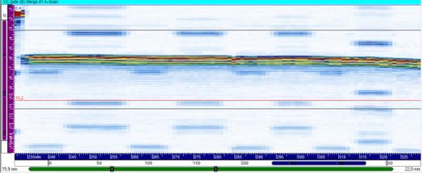
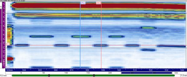
9 Figure 6 Zone 1 weld thickness profile. Figure 7 Zone 2 weld thickness profile Figure 8 Zone 3 weld thickness profile
10 4. Cracking Feeder Bends 4.1 Manual Bend Cracking Inspection Following the online failure of an outlet feeder in 1996, the CANDU industry responded by developing an inspection method addressing this degradation mechanism. The initial inspection zone was the bend area between the 3 and 9 o clock positions centered on the extrados (12 o clock). The first bend is in most cases accessible for manual inspection from the extrados. An inspection method and procedure addressing the COG inspection specifications was developed by the industry and validated using real flaws from removed feeders. The procedure was then qualified using cold bent feeder pipes containing thermal fatigue cracks (TFC) implanted at various locations in the area of interest. Several laboratory tests and the inspector qualification program conducted by each utility showed that the procedure is very effective in finding axially oriented internal surface breaking flaws near the intrados region with scanning passes centered on each side of the extrados [5]. In 2003, feeder inspection campaign detected feeder bends with cracks located in the second bend. Upon removal of the bend, non-destructive examination found additional cracking on the outside diameter (OD) of the second bend extrados. This crack was found in a different location and bend type than the previously cracked feeders and was outside of the COG inspection specification scope. The inspection procedure was updated and a special attention was also paid to scanning second bends because the extrados is not easily accessible for manual scanning. Alternate scanning techniques were experimented to alleviate the accessibility problem and thus expand the scope of the inspection procedure to include second bends. The manual procedure was further improved following operating experience and the latest revision which was qualified by the CQIB in March 2010 is COG-JP V18, Rev Bend Cracking Crawler Hydro-Quebec started the development of a manual data-recording method and in parallel, a motorized inspection system addressing the COG Inspection Specification. The main objective of these projects was to reduce the dose taken by the limited number of available level 2 ultrasonic operators. This is achieved using level 1 probe operators on the reactor face to manipulate transducers during manually recorded scanning and bracelet installation during motorized crawler inspections. The first generation of the bend cracking crawler (BCC) had four in-line transducers, two running on each side of the extrados, aimed toward the intrados. The drive motors were mounted on top of the crawler which fit between the end fittings of adjacent channels during scanning. The design is such that transducers are as close as possible to the cheeks and move together in an 18 mm raster motion. An inspection procedure making use of the unique features of a digital data-acquisition instrument and a motorized scanner was developed. The main improvement resides in the precise flaw positioning offered by an encoded device. The procedure was validated using a set of cold bent feeder pipes containing thermal fatigue

11 cracks. Several blind tests were conducted using trained and qualified HQ technicians with no flaws missed. In early January 2004, the COG decided to use the motorized crawler to inspect second bends that are difficult to access using the manual technique. The crawler had to be modified to access the second bends and to include the extrados in the inspection scope. Two modifications were undertaken. First, the two probes near the extrados were inverted to cover the upper half of the bend; secondly, the motors were relocated in order to reduce the overall height of the scanner to no more than 20 mm. Moving the motor made the crawler capable of accessing areas where the hand cannot reach and gave enough clearance to all second bends on a CANDU 6. The main benefit of motorizing the inspection is repeatability of inspection results which are totally independent of operator skills or access constraints. The manual technique calls for 3 scans performed twice with an index of 10 mm between each pass. Each manual scan is intentionally repeated to increase the probability that the operator did not skip any areas. The crawler provides the capability of four simultaneous passes in one scan, two passes toward the extrados and two passes directed toward the intrados. The crawler does not require scanning redundancy because the motors are controlled electronically and the inspection sequence cannot skip positions. After the successful performance demonstration, the industry selected Zetec to manufacture a rugged version of the latest crawler prototype. The commercial versions were made available in February Commercially available crawlers were used at PLGS and G2 during their 2006 to 2009 outages and on a trial basis at Darlington in The BCC procedure was qualified by the CIQB in Figure 9 Bend-Cracking-Crawler on feeder sample
12 4.3 Eddy Current Bend Crawler In 2005, several feeder bends were removed because the inspection techniques are very sensitive and artefacts such as inclusion in the base material or internal flow lines can results in an ultrasonic response above the disposition threshold. To avoid this situation, the industry developed a series of verification techniques to discriminate between real cracks from less minor reflectors. One verification method is a conventional wet fluorescent magnetic test applied for OD indications located on the extrados. For ID indications, the use of an ultrasonic amplitude-based comparison was developed to assess the reflectivity of a flaw from both sides. It was demonstrated experimentally that flow lines do not reflect sounds very well in both direction and that a simple comparative amplitude-bases test can differentiate real cracks from other artefacts. For OD cracks located on second bends, which makes the extrados facing the reactor, the access does not allow any visual technique to be applied. The industry developed a magnetic rubber replica procedure but it was found difficult under real condition to deploy. Hydro- Québec developed an eddy current sensor that can be mounted on the BCC and perform an automated surface examination on inaccessible second bend extrados. Results on mock-up samples with TFC prove to be an effective and repeatable technique for OD initiated cracks. 5. Cracking Feeder Welds 5.1 Manual Weld Inspection The weld crack was found in a field weld, an area not easily accessible for inspection. The proposed approach was to monitor all full penetration repairs on Grayloc welds. A conventional 2 fixed angles shear wave technique was not appropriate because of the close proximity of the first bend that made raster scanning unreliable. The only technically-sound approach was to use a phased-array probe and use its beam deflection capability to scan the volume of the Grayloc weld. With a phased-array probe, raster scanning became unnecessary and simplified the volumetric inspection of the weld. Figure 10 Grayloc weld cracking inspection A contact phased array ultrasonic (UT) examination procedure was developed by COG for the detection of circumferential flaws in CANDU PHT system Grayloc hub welds. This technique provides a full volumetric weld inspection for circumferentially oriented flaws,

13 360 around the weld circumference, by multiple line-scanning performed from the pipe side over the entire circumference. The inspection is done manually using specially designed alignment jigs and either an encoded delivery tool design by Eclipse Scientific, or the GAIT tool with the appropriate gimble. The procedure was developed and tested on nominal feeder pipe and on thinned cross-section samples representative of removed feeders. The wall thickness is measured and used during analysis. Figure 11 Clip tool for manual Grayloc weld inspection with alignment jig 5.2 GRAVIS Weld Cracking Automating the volumetric inspection of the Grayloc weld was a project funded by COG. The objective of the project was to design a 2-axis motorized scanner to deliver a phased-array probe to perform multiple circumferential scans with a small axial index. The advantage of this type of multiple line scan is to collect sufficient data along the axial axis in order to assess the echodynamic response of a suspicious indication. To discriminate between a crack and a side-wall lack of fusion, the echodynamic of a reflector is compare to the calibration notch. It is expected that a crack would normally propagate in a direction normal to the surface and its echodynamic should be similar to the calibration notch. This behaviour was compare against flawed samples and a known lack of side-wall fusion defect found in-service and it proved right. A lack of side wall fusion signal would peak at a high refracted beam angle while totally vanishing at lower angles. The Grayloc Area Volumetric Inspection System was design and manufactured by Zetec according to COG specifications. The GRAVIS is a general purpose pipe scanner with a mounting adaptor for the Grayloc flange, the Grayloc hub for shop-floor inspections or a pipeto-pipe weld clamp. The motorized unit is fixed on the mounting adaptor and provides motion of the probe holder in the orbital and axial directions. Then, a spring loaded probe holder developed specifically for the application wall thinning or volumetric inspection is affixed on the motorized unit. Calibration of the phased-array probe is performed with the probe in hand. The operator must scan several blocks to validate the wedge delay, elements, and create TCG curves for each angle. Once the calibration is completed, the probe is mounted on the GRAVIS and inspection can commence.

14 To get a simple mechanical system, cable handling is performed by the operator. He must carefully manage the cable as the probe orbits around the feeder pipe. Operating the GRAVIS involves a certain amount of dose to the operator, but the quality of the data and the capability of the procedure to discriminate geometric indication from real crack offset the dose taken by the operator during the data-acquisition phase. The collected data is analysed on-line and the entire volume of the weld is characterized in the matter of 1 or 2 minutes. Thanks to the feature of the software that creates 3-D views of the weld and the necessary top and side view for rapid identification of suspicious indications. Indication are then characterized in terms of amplitude and echodynamic in order to classify them as either an indication with vertical extension, which would likely be a crack, or a tilted indication which would be more likely a lack of side-wall fusion defect type. Any flaw acceptable in terms of amplitude (as per CSA N-285.4) or echodynamic would be revisited at the next outage to verify if any growth is observed. Figure 12 GRAVIS configured for weld cracking inspection. 6. Conclusions This paper described an overview of the improvements in work practices and tooling for a challenging non-destructive evaluation application. The use of automated tooling at Gentilly-2 vastly improved the feeder inspection data quality and reliability, worker s safety and production rate, while reducing the dose intake by tooling operators. Furthermore, inspection results become independent of operator skills and human errors. However, since these tools are more complex to operate, extensive training programs in simulation environment are required for efficient use of the instrumentation controls by the acquisition personnel. Automated NDE tooling has proven to be highly effective but only when such training are performed. Future development in thickness measurements tooling should allow nuclear operators to similarly improve the efficiency of their planned outages for feeder thickness and cracking inspections.
15
16 References 1. Flow Accelerated Corrosion and Cracking of Carbon Steel Piping in Primary Water - Operating Experience at the Point Lepreau Generating Station, John P. Slade, Tracy S., Gendron, Proceedings of the 12th International Conference on Environmental Degradation of Materials in Nuclear Power System, "Hydro-Québec METAR Inspection Bracelet", E. Lavoie, G. Rousseau, J. Lessard, A. Drolet; CNS 5th International Conference on CANDU Maintenance, November "On the Development of the MÉTAR Family Inspection Tools ", E. Lavoie, G. Rousseau and L. Raynaud; CNS 6th International Conference on CANDU Maintenance, November Recent Progress in Phased Array UT Inspection through Complex and Waby Surfaces, P. Tremblay, S. Turgeon, D. Reilly and G. Maes, Development of Ultrasonic Techniques for Feeder Cracking Inspection at Gentilly-2", G. Rousseau, J-F. Coté, G. Lepage and E. Lavoie; CNS 6th International Conference on CANDU Maintenance, November 2003.
EXAMINATION OF NOZZLE INNER RADIUS AND PIPING FROM THE OUTER SURFACE
 More Info at Open Access Database www.ndt.net/?id=18560 ABSTRACT NEW DEVELOPMENTS FOR AUTOMATED NOZZLE INNER RADIUS AND PIPING INSPECTIONS D. Eargle,WesDyne International, USA WesDyne has recently engaged
INSPECTION TECHNIQUE FOR BWR CORE SPRAY THERMAL SLEEVE WELD
 More Info at Open Access Database www.ndt.net/?id=18479 INSPECTION TECHNIQUE FOR BWR CORE SPRAY THERMAL SLEEVE WELD ABSTRACT J.L. Fisher, G. Light, Jim Crane, Albert Parvin, Southwest Research Institute,
ULTRASONIC EXAMINATION
 Page 1 of 9 ULTRASONIC EXAMINATION PROCEDURE Doc. No. KNS/UT/01.REV 0 Page: 9 of 9 Date: 15.09.2012 ULTRASONIC EXAMINATION PROCEDURE PREPARED & APPROVED BY NDE- Level III CERTIFIED BY REVIEWED BY Page
Visual Inspection of Reactor Vessel Head Penetration Nozzles
 International Conference Nuclear Energy for New Europe 2003 Portorož, Slovenia, September 8-11, 2003 http://www.drustvo-js.si/port2003 Visual Inspection of Reactor Vessel Head Penetration Nozzles Simon
Key-Words : Eddy Current Testing, Garter Spring, Coolant Channels, Eddy Current Test Coil Design etc.
 More Info at Open Access Database www.ndt.net/?id=15054 Development of Eddy Current Test Technique for Detection of Garter Springs in 540 and 700 MWe Pressurized Heavy Water Reactors Arbind Kumar AFD,
ULTRASONIC TESTING OF RAILWAY AXLES WITH PHASED ARRAY TECHNIQUE EXPERIENCES DURING OPERATION
 ULTRASONIC TESTING OF RAILWAY AXLES WITH PHASED ARRAY TECHNIQUE EXPERIENCES DURING OPERATION W. Hansen 1, H. Hintze 2 1 GE Inspection Technologies, Hürth, Germany; 2 Deutsche Bahn AG, Kirchmöser; Germany
ESTABLISHMENT OF ULTRASONIC TESTING IN UNIQUE DESIGNED PARTIAL PENETRATION END PLUG OF HEADER IN BOILERS.
 Proceedings of the National Seminar & Exhibition on Non-Destructive Evaluation NDE 2011, December 8-10, 2011 ESTABLISHMENT OF ULTRASONIC TESTING IN UNIQUE DESIGNED PARTIAL PENETRATION END PLUG OF HEADER
p h a s e d - a r r a y t e c h n o l o g i e s w w w. m 2 m - n d t. c o m
 A new advanced portable phased - array system : the Mantis Phased-array technology Phased-array technology has been widely accepted in the industry as a powerful tool for the detection of corrosion and
Ultrasonic and Magnetic Particle Testing of New Railway Wheels
 19 th World Conference on Non-Destructive Testing 2016 Ultrasonic and Magnetic Particle Testing of New Railway Wheels Wolfram A. Karl DEUTSCH 1, Wolfgang WEBER 1, Klaus MAXAM 1, Mathias RAZENG 1, Frank
Primary Heat Transport (PHT) Motor Rotor Retaining Ring Failure
 Motor Rotor Retaining Ring Failure") 1 Primary Heat Transport (PHT) Motor Rotor Retaining Ring Failure Ali Malik Components & Equipment Eng. Ontario Power Generation - Darlington Nuclear 2 Ontario Power Generation Darlington Darlington Nuclear
1 Primary Heat Transport (PHT) Motor Rotor Retaining Ring Failure Ali Malik Components & Equipment Eng. Ontario Power Generation - Darlington Nuclear 2 Ontario Power Generation Darlington Darlington Nuclear
Detection and evaluation of rail defects with nondestructive
 19 th World Conference on Non-Destructive Testing 2016 Detection and evaluation of rail defects with nondestructive testing methods Anika DEY 1, Jochen KURZ 2, Lukasz TENCZYNSKI 3 1 DB Systemtechnik GmbH
New Robotic Technologies for Inspecting Two Pole Electric Generators while the Rotor Remains in Place
 Journal of Power and Energy Engineering, 2015, 3, 123-127 Published Online April 2015 in SciRes. http://www.scirp.org/journal/jpee http://dx.doi.org/10.4236/jpee.2015.34018 New Robotic Technologies for
Ultrasonic Inspection Equipment for Al-Fin Insert Diesel Pistons
 A Paper By Mark Willcox Telephone +44 (0)1981 541122 Fax +44 (0)1981 541133 Email Sales@InsightNDT.com Web Site www.insightndt.com Insight NDT Equipment Ltd The Old Cider Mill Kings Thorn Herefordshire
Oconee Nuclear Station ALLOY 600 REPAIRS 1EOC23
 Oconee Nuclear Station ALLOY 600 REPAIRS 1EOC23 We re requiring more inspections due to susceptibility of material to cracking Some utilities have implemented mitigative actions Stress improvement Weld
ARTICLE 5 ULTRASONIC EXAMINATION METHODS FOR MATERIALS
 ARTICLE 5 ULTRASONIC EAMINATION METHODS FOR MATERIALS 04 T-510 SCOPE This Article provides or references requirements, which are to be used in selecting and developing ultrasonic examination procedures
Development of Relief Valve Automatic assembly technology
 Development of Relief Valve Automatic assembly technology Technology Explanation Development of Relief Valve Automatic assembly technology TAKIGUCHI Masaki Abstract Construction machinery is equipped with
DEVELOPMENT OF NEW MANIPULATORS FOR PWR AND VVER VESSEL INSPECTION. Authors: Mats Wendel and Torbjörn Sjö, DEKRA Industrial, Sweden
 DEVELOPMENT OF NEW MANIPULATORS FOR PWR AND VVER VESSEL INSPECTION Authors: Mats Wendel and Torbjörn Sjö, DEKRA Industrial, Sweden ABSTRACT TIME, has been the key word for the inspection of Ringhals PWR
TSC INSPECTION SYSTEMS
 TSC INSPECTION SYSTEMS APPLICATIONS OF ACFM IN THE RAIL INDUSTRY ACFM was originally developed for use in the oil and gas industry as a technique for detecting and sizing surface-breaking defects with
Figures T Basic Calibration Block T Straight Beam Calibration Blocks for Bolting
 A02 ARTICLE 5 T-510 Scope... 102 T-520 General... 102 T-521 Basic Requirements... 102 T-522 Written Procedure Requirements... 102 T-530 Equipment... 102 T-531 Instrument... 102 T-532 Search Units... 102
Use of Flow Network Modeling for the Design of an Intricate Cooling Manifold
 Use of Flow Network Modeling for the Design of an Intricate Cooling Manifold Neeta Verma Teradyne, Inc. 880 Fox Lane San Jose, CA 94086 neeta.verma@teradyne.com ABSTRACT The automatic test equipment designed
Permanent Multipath Clamp-On Transit Time Flow Meter
 Permanent Multipath Clamp-On Transit Time Flow Meter By: Dr. J. Skripalle HydroVision GmbH, Germany Introduction For many years now, ultrasonic flow measurements with wetted sensors have been a well established
Prevention vs. Reaction The Importance of Asset Integrity
 Prevention vs. Reaction The Importance of Asset Integrity How Your Assets Typically Age Inspections Potential Failure Condition Functional Failure Time P-F Interval Why is Asset Integrity so Important?
Post Irradiation Examinations of High Performance Research Reactor Fuels
 Post Irradiation Examinations of High Performance Research Reactor Fuels www.inl.gov National Academy of Science Technical Review Francine Rice, Walter Williams, Daniel Wachs, Mitchell Meyer, Adam Robinson
FUNDAMENTAL SAFETY OVERVIEW VOLUME 2: DESIGN AND SAFETY CHAPTER E: THE REACTOR COOLANT SYSTEM AND RELATED SYSTEMS
 PAGE : 1 / 13 4. PRESSURISER 4.1. DESCRIPTION The pressuriser (PZR) is a pressurised vessel forming part of the reactor coolant pressure boundary (CPP) [RCPB]. It comprises a vertical cylindrical shell,
Robotics and Manipulators for Reactor Pressure Vessel Head Inspection
 International Journal of Nuclear Ene rgy Science and Engineering Vol. 2 Iss. 4, De cember 2012 Robotics and Manipulators for Reactor Pressure Vessel Head Inspection S.W. Glass 1, M.Sloman 2, F.Klahn 3
SPEED PROBE INSTALLATION GUIDELINES PAGE 1 DOCUMENT REFERENCE: LCC /26/2000
 SPEED PROBE INSTALLATION GUIDELINES PAGE 1 APPLICATIONS: SUBJECT: LCC MODEL 470 DIGITAL SPEED MONITOR LCC SERIES 200 DISTRIBUTED CONTROL SYSTEMS LCC SERIES 2 GOVERNORS LCC SERIES 2 TSI INSTALLATION GUIDELINES
Improving predictive maintenance with oil condition monitoring.
 Improving predictive maintenance with oil condition monitoring. Contents 1. Introduction 2. The Big Five 3. Pros and cons 4. The perfect match? 5. Two is better than one 6. Gearboxes, for example 7. What
Special edition paper
 Efforts for Greater Ride Comfort Koji Asano* Yasushi Kajitani* Aiming to improve of ride comfort, we have worked to overcome issues increasing Shinkansen speed including control of vertical and lateral
THE APPLICATION OF LONG RANGE GUIDED ULTRASONICS FOR THE INSPECTION OF RISER PIPES
 THE APPLICATION OF LONG RANGE GUIDED ULTRASONICS FOR THE INSPECTION OF RISER PIPES J. McGregor, B. Nooteboom, N. Ivory PTAS-ITS Lot 1 and 2 Tapak Perindustrian Pekan Belait, Jalan Setia Di-Raja, Kuala
Ultrasonic Production Monitoring of Small Diameter ERW Pipes
 11th European Conference on Non-Destructive Testing (ECNDT 2014), October 6-10, 2014, Prague, Czech Republic Ultrasonic Production Monitoring of Small Diameter ERW Pipes Mirek Macecek, Pavel Vraj Techno
NRC Non-Destructive Examination Research
 NRC Non-Destructive Examination Research Office of Nuclear Regulatory Research U.S. Nuclear Regulatory Commission Jeff Hixon October 22, 2009 Why NDE? U.S. Nuclear Regulatory Commission 2 Why NDE? U.S.
Improving the Quality of NDT in the Rail Sector through the Introduction of Advanced Technologies and NDT Means
 More Info at Open Access Database www.ndt.net/?id=15123 Improving the Quality of NDT in the Rail Sector through the Introduction of Advanced Technologies and NDT Means O. Iurchenko 8 Naberezhno-Lugova
Integrity Evaluation of Steam Line Using Complimentary NDE Methods (Acoustic Emission and Ultrasonic Testing)
") 131 Integrity Evaluation of Steam Line Using Complimentary NDE Methods (Acoustic Emission and Ultrasonic Testing) K. Rajeev and K.S. Prasanth Proceedings of the National Seminar & Exhibition on Non-Destructive
131 Integrity Evaluation of Steam Line Using Complimentary NDE Methods (Acoustic Emission and Ultrasonic Testing) K. Rajeev and K.S. Prasanth Proceedings of the National Seminar & Exhibition on Non-Destructive
Principles of NDT Methods on Railway Axles
 Sheet 1 of 38 Dipl.-Ing. Thomas Heckel, BAM VIII.43 Dipl.Ing. Uwe Völz, BAM VIII.43 Dipl.-phys. Rainer Boehm, BAM VIII.42 11.10.2010 Sheet 2 of 38 1. Introduction 2. NDT by manufacturer 3. In-service inspection
A Recommended Approach to Pipe Stress Analysis to Avoid Compressor Piping Integrity Risk
 A Recommended Approach to Pipe Stress Analysis to Avoid Compressor Piping Integrity Risk by: Kelly Eberle, P.Eng. Beta Machinery Analysis Calgary, AB Canada keberle@betamachinery.com keywords: reciprocating
Comprehensive Management of Hydrocarbon Storage Tanks Ageing
 ECNDT 2006 - Fr.2.2.2 Comprehensive Management of Hydrocarbon Storage Tanks Ageing Vincent LESUEUR, Mathieu RIETHMULLER, Daniel CHAUVEAU, IS Services, France Abstract. Corrosion generates considerable
Simulating Rotary Draw Bending and Tube Hydroforming
 Abstract: Simulating Rotary Draw Bending and Tube Hydroforming Dilip K Mahanty, Narendran M. Balan Engineering Services Group, Tata Consultancy Services Tube hydroforming is currently an active area of
Differential Expansion Measurements on Large Steam Turbines
 Sensonics Technical Note DS1220 Differential Expansion Measurements on Large Steam Turbines One of the challenges facing instrumentation engineers in the power generation sector is the accurate measurement
NON-INTRUSIVE INSPECTION OF ABOVE GROUND STORAGE TANKS AND ITS USE IN A TANK RBI PROGRAM
 September/October 2013 Volume 19, Issue 5 Since 1995, Inspectioneering Journal has provided the oil & gas and chemical industries with information to help optimally manage equipment risk and reliability,
Robotic Inspection of Unpiggable Piping at Pump Station
 Robotic Inspection of Unpiggable Piping at Pump Station by Steve Lacatena 1 and Jonathan Minder 2 1 Alyeska Pipeline Service Co, Anchorage, AK, USA 2 Diakont, San Diego, CA USA Unpiggable Pipeline Solutions
Urea Reactor Height Extension to Increase Capacity
 Technical Paper June 2014 Urea Reactor Height Extension to Increase Capacity Hermann Kernberger Schoeller-Bleckmann Nitec GmbH (SBN), Austria Bob Edmondson Yara Belle Plaine, Canada Summary A discussion
Computer-Assisted Induction Aluminum
 Home Computer-Assisted Induction Aluminum Brazing November 11, 2003 Coupled electromagnetic and thermal computer simulation provides a sufficient basis for process optimization and quality improvement
REGULATORY CONTROL OF NUCLEAR FUEL AND CONTROL RODS
 REGULATORY CONTROL OF NUCLEAR FUEL AND CONTROL RODS 1 GENERAL 3 2 PRE-INSPECTION DOCUMENTATION 3 2.1 General 3 2.2 Initial core loading of a nuclear power plant, new type of fuel or control rod or new
Saab Avitronics THE CHALLENGES OF DEVELOPING A COMINT DF AND MONITORING ANTENNA FOR THE HIGH PRESSURE ENVIRONMENT OF SUBMARINE OPERATIONS
 Saab Avitronics THE CHALLENGES OF DEVELOPING A COMINT DF AND MONITORING ANTENNA FOR THE HIGH PRESSURE ENVIRONMENT OF SUBMARINE OPERATIONS Dr Dirk Baker Saab Avitronics P O Box 8429 Centurion dirk.baker@za.saabgroup.com
Centerwide System Level Procedure
 5.ARC.0004.2 1 of 10 REVISION HISTORY REV Description of Change Author Effective Date 0 Initial Release J. Hanratty 7/17/98 1 Clarifications based on 7/98 DNV Audit and 6/98 Internal Audit (see DCR 98-029).
PIPELINE REPAIR OF CORROSION AND DENTS: A COMPARISON OF COMPOSITE REPAIRS AND STEEL SLEEVES
 Proceedings of the 2014 10th International Pipeline Conference IPC2014 September 29 - October 3, 2014, Calgary, Alberta, Canada IPC2014-33410 PIPELINE REPAIR OF CORROSION AND DENTS: A COMPARISON OF COMPOSITE
Algeria, November 2016
 Advanced Non-Destructive Testing for Tanks and Pipelines Algeria, November 2016 Params. K Details of Selected Advanced NDT Techniques On-Line Inspection What is On-Line Inspection? Check the Mechanical
CANDU Fuel Bundle Deformation Model
 CANDU Fuel Bundle Deformation Model L.C. Walters A.F. Williams Atomic Energy of Canada Limited Abstract The CANDU (CANada Deuterium Uranium) nuclear power plant is of the pressure tube type that utilizes
TRAINSAFE SAFE INFRASTRUCTURE WORKSHOP DEMONSTRATION OF THE RESEARCH CLUSTER MECHANISM FOR INSPECTION TECHNOLOGIES
 TRAINSAFE SAFE INFRASTRUCTURE WORKSHOP DEMONSTRATION OF THE RESEARCH CLUSTER MECHANISM FOR INSPECTION TECHNOLOGIES STAGE 1 ISSUE HIGHLIGHTED IN THE STATE OF THE ART REPORT This resulted in the topic of
Development of GE4i Cylindrical Grinder
 TECHNICAL REPORT Development of GE4i Cylindrical Grinder H. NAGAYA The medium size cylindrical grinder, which is one of our company s main machine tools, has been fully remodeled to suit the needs of the
Defect Monitoring In Railway Wheel and Axle
 IJR International Journal of Railway, pp. 1-5 The Korean Society for Railway Defect Monitoring In Railway Wheel and Axle Seok-Jin Kwon, Dong-Hyoung Lee *, and Won-Hee You * Abstract The railway system
Chemical decontamination in nuclear systems radiation protection issues during planning and realization
 Chemical decontamination in nuclear systems radiation protection issues during planning and realization F. L. Karinda, C. Schauer, R. Scheuer TÜV SÜD Industrie Service GmbH, Westendstrasse 199, 80686 München
DACON INSEPECTION SERVICES CORROSION UNDER SUPPORT
 DACON INSEPECTION SERVICES CORROSION UNDER SUPPORT Who we are Conventional and Advanced NDT and Inspection Services Oil and Gas, Refinery, Petrochemical, Heavy Industry, Mining Over 400 personnel including
APPLICATION OF STAR-CCM+ TO TURBOCHARGER MODELING AT BORGWARNER TURBO SYSTEMS
 APPLICATION OF STAR-CCM+ TO TURBOCHARGER MODELING AT BORGWARNER TURBO SYSTEMS BorgWarner: David Grabowska 9th November 2010 CD-adapco: Dean Palfreyman Bob Reynolds Introduction This presentation will focus
IMPROVING SULFURIC ACID PLANT PERFORMANCE THROUGH NEW SHAPE & HIGHER ACTIVITY CATALYSTS
 IMPROVING SULFURIC ACID PLANT PERFORMANCE THROUGH NEW SHAPE & HIGHER ACTIVITY CATALYSTS BY: TIMOTHY R. FELTHOUSE, Ph.D; MARIO P. DIGIOVANNI, P.E.; JOHN R. HORNE AND SARAH A. RICHARDSON PRESENTED AT: THE
Effects of shaft geometric unconformities on the rotor-dynamic behavior in hard coupled equipment
 Effects of shaft geometric unconformities on the rotor-dynamic behavior in hard coupled equipment Gianluca Boccadamo Paolo Agnoletti Gaspare Maragioglio Authors Gianluca Boccadamo Lead Engineer Shaft Line
Application Note Original Instructions Development of Gas Fuel Control Systems for Dry Low NOx (DLN) Aero-Derivative Gas Turbines
 Aero-Derivative Gas Turbines") Application Note 83404 Original Instructions Development of Gas Fuel Control Systems for Dry Low NOx (DLN) Aero-Derivative Gas Turbines Woodward reserves the right to update any portion of this publication
Application Note 83404 Original Instructions Development of Gas Fuel Control Systems for Dry Low NOx (DLN) Aero-Derivative Gas Turbines Woodward reserves the right to update any portion of this publication
SUBMARINE NOZZLE PIPE MANIPULATOR. R. Zeilinger, G. Hünies, F. Mohr AREVA NDE-Solutions/ intelligendt Systems & Services GmbH
 SUBMARINE NOZZLE PIPE MANIPULATOR R. Zeilinger, G. Hünies, F. Mohr AREVA NDE-Solutions/ intelligendt Systems & Services GmbH ABSTRACT: AREVA NDE-Solutions German division - intelligendt Systems & Services
ADVANCE INSPECTION TECHNOLOGIES APPLIED TO THE GAS INDUSTRY Mar del Plata Octubre 2012
 ADVANCE INSPECTION TECHNOLOGIES APPLIED TO THE GAS INDUSTRY Mar del Plata Octubre 2012 LEADING IN INSPECTION TECHNOLOGIES Ruben Bermudez Rosen Europe BV Introduction In-Line Inspection of gas pipelines
High-Speed Ultrasonic Testing of ERW Pipes
 19 th World Conference on Non-Destructive Testing 2016 High-Speed Ultrasonic Testing of ERW Pipes W.A.K. DEUTSCH 1, M. JOSWIG 1, R. KATTWINKEL 1, H. HARMUTH 1 1 KARL DEUTSCH Prüf- und Messgerätebau GmbH
REMOTE SENSING DEVICE HIGH EMITTER IDENTIFICATION WITH CONFIRMATORY ROADSIDE INSPECTION
 Final Report 2001-06 August 30, 2001 REMOTE SENSING DEVICE HIGH EMITTER IDENTIFICATION WITH CONFIRMATORY ROADSIDE INSPECTION Bureau of Automotive Repair Engineering and Research Branch INTRODUCTION Several
Global VPI Insulated Indirectly Hydrogen-Cooled Turbine Generator for Single-Shaft Type Combined Cycle Power Generation Facilities
 Global VPI Insulated Indirectly Hydrogen-Cooled Turbine Generator for Single-Shaft Type Combined Cycle Power Generation Facilities YAMAZAKI Masaru NIIKURA Hitoshi TANIFUJI Satoshi ABSTRACT Fuji Electric
INFLUENCE OF CROSS FORCES AND BENDING MOMENTS ON REFERENCE TORQUE SENSORS FOR TORQUE WRENCH CALIBRATION
 XIX IMEKO World Congress Fundamental and Applied Metrology September 6 11, 2009, Lisbon, Portugal INFLUENCE OF CROSS FORCES AND BENDING MOMENTS ON REFERENCE TORQUE SENSORS FOR TORQUE WRENCH CALIBRATION
Application of Phased Array Ultrasonic Testing Technology on Inservice Wheel
 18th World Conference on Nondestructive Testing, 16-20 April 2012, Durban, South Africa Application of Phased Array Ultrasonic Testing Technology on Inservice Wheel Yu ZHANG 1, Li WANG 1, Jianping PENG
Fatigue properties of railway axles: new results of full-scale specimens
 Fatigue properties of railway axles: new results of full-scale specimens Steven Cervello Lucchini RS, Italy TC24 Meeting Advances in: Axle Durability Analysis and Maintenance Politecnico di Milano 1-2
MB3600-CH30 Laboratory FT-NIR analyzer for biodiesel applications Suitable for production optimization and product quality assessment
 Measurement & Analytics Measurement made easy MB3600-CH30 Laboratory FT-NIR analyzer for biodiesel applications Suitable for production optimization and product quality assessment FT-NIR optimizing productivity
Seeing Sound: A New Way To Reduce Exhaust System Noise
 \ \\ Seeing Sound: A New Way To Reduce Exhaust System Noise Why Do You Need to See Sound? Vehicle comfort, safety, quality, and driver experience all rely on controlling the noise made by multiple systems.
LEVER OPTIMIZATION FOR TORQUE STANDARD MACHINES
 LEVER OPTIMIZATION FOR TORQUE STANDARD MACHINES D. Röske, K. Adolf and D. Peschel Torque laboratory Division for Mechanics and Acoustics Phys.-Techn. Bundesanstalt, D-38116 Braunschweig, Germany Abstract:
NZQA unit standard version 5 Page 1 of 6. Demonstrate knowledge of engine design factors and machining practices
 Page 1 of 6 Title Demonstrate knowledge of engine design factors and machining practices Level 4 Credits 20 Purpose People credited with this unit standard are able to demonstrate knowledge of engine design
Phased Array Integrated Instrumentation
 Phased Array Acquisition Unit Phased Array Integrated Instrumentation Powerful Scalable Excellent signal quality Rugged and compact Easy integration Phased Array Instrumentation Designed for Demanding
Switch design optimisation: Optimisation of track gauge and track stiffness
 1 Switch design optimisation: Optimisation of track gauge and track stiffness Elias Kassa Professor, Phd Department of Civil and Transport Engineering, NTNU Trondheim, Norway E-mail: elias.kassa@ntnu.no
Evolving Bump Chip Carrier
 FUJITSU INTEGRATED MICROTECHNOLOGY LIMITED. The Bump Chip Carrier, which was developed as a small pin type, miniature, and lightweight CSP, is not only extremely small due to its characteristic structure,
QUARTER SCALE ROBOTICS POSITOING SYSTEM
 ME 4773/5493 Fundamental of Robotics Fall 2016 San Antonio, TX, USA QUARTER SCALE ROBOTICS POSITOING SYSTEM Andres Favela Student San Antonio, TX, USA 78249 Afave91@gmail.com ABSTRACT As of 2015 nearly
VBK 2596/12E/RSF. Thickness and Width Gauge for Strip and Profile. Operating- & Service Instructions. (with lateral guide rollers)
") Thickness and Width Gauge for Strip and Profile (with lateral guide rollers) VBK 2596/12E/RSF Operating- & Service Instructions erstellt am 5.2.1998 freigegeben am Bemerkungen Rev.01 Seiten:16 Name: Rietdorf
Thickness and Width Gauge for Strip and Profile (with lateral guide rollers) VBK 2596/12E/RSF Operating- & Service Instructions erstellt am 5.2.1998 freigegeben am Bemerkungen Rev.01 Seiten:16 Name: Rietdorf
STEALTH INTERNATIONAL INC. DESIGN REPORT #1001 IBC ENERGY DISSIPATING VALVE FLOW TESTING OF 12 VALVE
 STEALTH INTERNATIONAL INC. DESIGN REPORT #1001 IBC ENERGY DISSIPATING VALVE FLOW TESTING OF 12 VALVE 2 This report will discuss the results obtained from flow testing of a 12 IBC valve at Alden Research
PVP Field Calibration and Accuracy of Torque Wrenches. Proceedings of ASME PVP ASME Pressure Vessel and Piping Conference PVP2011-
 Proceedings of ASME PVP2011 2011 ASME Pressure Vessel and Piping Conference Proceedings of the ASME 2011 Pressure Vessels July 17-21, & Piping 2011, Division Baltimore, Conference Maryland PVP2011 July
BY: Paul Behnke ITT Industries, Industrial Process. Juan Gamarra Mechanical Solutions, Inc.
 DRIVE SHAFT FAILURE ANALYSIS ON A MULTISTAGE VERTICAL TURBINE PUMP IN RIVER WATER SUPPLY SERVICE IN A NICKEL AND COBALT MINE IN I MADAGASCAR -BASED ON ODS AND FEA Juan Gamarra Mechanical Solutions, Inc.
Field Verification and Data Analysis of High PV Penetration Impacts on Distribution Systems
 Field Verification and Data Analysis of High PV Penetration Impacts on Distribution Systems Farid Katiraei *, Barry Mather **, Ahmadreza Momeni *, Li Yu *, and Gerardo Sanchez * * Quanta Technology, Raleigh,
ADVANCED INSPECTION TECHNIQUE FROM INSIDE SURFACE FOR DISSIMILAR METAL WELD OF STEAM GENERATOR NOZZLE
 More Info at Open Access Database www.ndt.net/?id=18532 ADVANCED INSPECTION TECHNIQUE FROM INSIDE SURFACE FOR DISSIMILAR METAL WELD OF STEAM GENERATOR NOZZLE T. Yamaguchi, T. Shichida, T. Matsuura, Y.
Numerical simulation of detonation inception in Hydrogen / air mixtures
 Numerical simulation of detonation inception in Hydrogen / air mixtures Ionut PORUMBEL COMOTI Non CO2 Technology Workshop, Berlin, Germany, 08.03.2017 09.03.2017 Introduction Objective: Development of
2017 Water Reactor Fuel Performance Meeting September 10 (Sun) ~ 14 (Thu), 2017 Ramada Plaza Jeju Jeju Island, Korea
 ~ 14 (Thu), 2017 Ramada Plaza Jeju Jeju Island, Korea") Plant and Cycle Specific Fuel Assembly Bow Evolution Assessment Yuriy Aleshin 1, Jorge Muñoz Cardador 2 1 Westinghouse Electric Company LLC, PWR Fuel Technology: 5801 Bluff Road, Hopkins, SC 29061 - USA
Plant and Cycle Specific Fuel Assembly Bow Evolution Assessment Yuriy Aleshin 1, Jorge Muñoz Cardador 2 1 Westinghouse Electric Company LLC, PWR Fuel Technology: 5801 Bluff Road, Hopkins, SC 29061 - USA
GB NDT AXLE TESTING & DEFECT TYPES FOUND
 Applied Inspection Ltd GB NDT AXLE TESTING & DEFECT TYPES FOUND ESIS TC24 Workshop at RSSB 03/04 March 2011 Presented by Roy Archer (Technical Manager Rail - Level 3) Manual ultrasonic testing used for
Super-Critical Water-cooled Reactor
 Super-Critical Water-cooled Reactor SCWR System Steering Committee Y.P. Huang (Chair, China) L. Leung (Co-Chair, Canada, Presenter) R. Novotny (EU, awaiting confirmation) A. Sedov (Russian Federation)
Measuring equipment for the development of efficient drive trains using sensor telemetry in the 200 C range
 News Measuring equipment for the development of efficient drive trains using sensor telemetry in the 200 C range Whether on the test stand or on the road MANNER Sensortelemetrie, the expert for contactless
Verifying the accuracy of involute gear measuring machines R.C. Frazer and J. Hu Design Unit, Stephenson Building, University ofnewcastle upon Tyne,
 Verifying the accuracy of involute gear measuring machines R.C. Frazer and J. Hu Design Unit, Stephenson Building, University ofnewcastle upon Tyne, Abstract This paper describes the most common methods
WELD CRAWLER TM HIGHLY FLEXIBLE & ADAPTABLE SCANNER FOR WELD INSPECTIONS TRANSFORMING WELD INSPECTIONS.
 WELD CRAWLER TM HIGHLY FLEXIBLE & ADAPTABLE SCANNER FOR WELD INSPECTIONS TRANSFORMING WELD INSPECTIONS www.zetec.com VERSATILE: EASY TRANSFORMATION TO ADAPT TO CIRCUMFERENTIAL AND AXIAL WELDS FLEXIBLE
Experiences in a Motor Protection Retrofit
 Special Feature by Kyle Craig, Ontario Power Generation Amy Sinclair, Schweitzer Engineering Laboratories, Inc. Experiences in a Motor Protection Retrofit Introduction The initial stage of any project
EMS ELONGATION MEASUREMENT SYSTEM. Strain measurement system for wind turbines optimizing the control & condition monitoring
 EMS ELONGATION MEASUREMENT SYSTEM Strain measurement system for wind turbines optimizing the control & condition monitoring 2 1 1 3 3 EMS ELONGATION MEASUREMENT SYSTEM 1 Rotor blade Rotor blades are the
Variable Valve Drive From the Concept to Series Approval
 Variable Valve Drive From the Concept to Series Approval New vehicles are subject to ever more stringent limits in consumption cycles and emissions. At the same time, requirements in terms of engine performance,
Development of Rattle Noise Analysis Technology for Column Type Electric Power Steering Systems
 TECHNICAL REPORT Development of Rattle Noise Analysis Technology for Column Type Electric Power Steering Systems S. NISHIMURA S. ABE The backlash adjustment mechanism for reduction gears adopted in electric
The Deployable Gage Restraint Measurement System - Description and Operational Performance
 The Deployable Gage Restraint Measurement System - Description and Operational Performance GARY A. MARTIN ENSCO, INC 5400 PORT ROYAL ROAD SPRINGFIELD, VA 22151 703-321-4513 703-321-7619 (FAX) JEFFREY A.
Finite Element Analysis of Clutch Piston Seal
 Finite Element Analysis of Clutch Piston Seal T. OYA * F. KASAHARA * *Research & Development Center Tribology Research Department Three-dimensional finite element analysis was used to simulate deformation
Manufacturing Instructions Blank parts and semi-finished products
 May 2016 Manufacturing Instructions Blank parts and semi-finished products SN 200-2 ICS 25.020 Dimensions in mm Supersedes SN 200-2:2010-09 Table of contents Page 1 Scope... 2 2 Normative references...
Dynamic Balancing. Need a high-speed balance? No problem.
 Dynamic Balancing TOSHIBA is one of North America s leading turbine/generator service providers. Our unique highspeed balance and overspeed facility assures that proper balance is achieved prior to returning
Fluid Flow Conditioning
 Fluid Flow Conditioning March 2014 Flow Conditioning There is no flow meter on the market that needs flow conditioning. All flow meters are effective without any type of flow conditioning. 1 Flow Conditioning
Pulsed Eddy Current (PEC) Probe Catalog. March 2017
 Probe Catalog. March 2017") Pulsed Eddy Current (PEC) Probe Catalog March 2017 Disclaimer The information in this document is accurate as of its publication. Actual products may differ from those presented herein. 2017 Eddyfi. Eddyfi,
Pulsed Eddy Current (PEC) Probe Catalog March 2017 Disclaimer The information in this document is accurate as of its publication. Actual products may differ from those presented herein. 2017 Eddyfi. Eddyfi,
Health Monitoring of Rotating Equipment from Torsional Vibration Features
 College of Engineering Health Monitoring of Rotating Equipment from Torsional Vibration Features Martin W. Trethewey Department of Mechanical and Nuclear Engineering Penn State University April 13, 2007
Design and Test of Transonic Compressor Rotor with Tandem Cascade
 Proceedings of the International Gas Turbine Congress 2003 Tokyo November 2-7, 2003 IGTC2003Tokyo TS-108 Design and Test of Transonic Compressor Rotor with Tandem Cascade Yusuke SAKAI, Akinori MATSUOKA,
Joint Technical Meeting
 Joint Technical Meeting Development in the Assessment and Management of Pipeline Dents and Mechanical Damage: Putting Research into Practice By: SC Rapp and GT Vervake (Presenter) Spectra Energy AD Batte
A Practical Guide to Free Energy Devices
 A Practical Guide to Free Energy Devices Part PatD11: Last updated: 3rd February 2006 Author: Patrick J. Kelly Electrical power is frequently generated by spinning the shaft of a generator which has some