Multi-tool 2CV / Visa
|
|
|
- Andrew Carroll
- 5 years ago
- Views:
Transcription
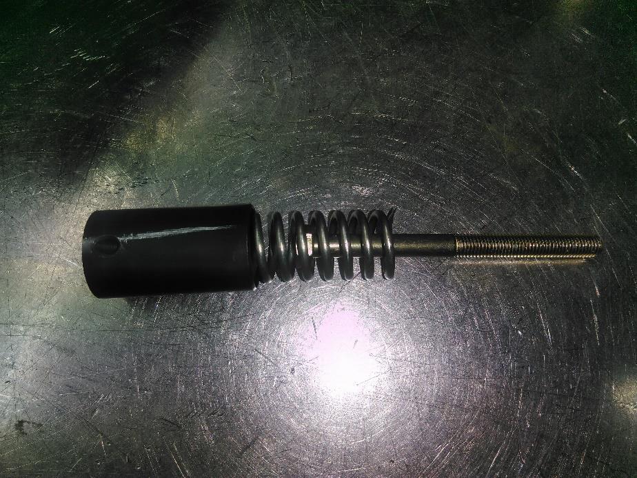
1 Multi-tool 2CV / Visa For the professional 2CV specialist / perfectionist: The heart of the engine, the crankshaft and camshaft often needs a (partial) revision. There are many new 2CV parts, but for these essential parts, there s hardly any alternatives. However, these parts create the difference between a car that just does its job (which is driving), or a smooth running 2CV This tool creates a number of possibilities: from now on you can check the condition of the crankshaft and the camshaft yourself. You also have the possibility to do some essential jobs yourself. VGS developed this tool because they noticed an increasing demand for camshaft timing. But it s a bit crazy to ship crankshafts and camshafts throughout Europe for a job that hardly takes an hour. With this tool, you, as 2CV technician can do a number of important jobs yourself. The tool was developed by VGS. They sell original sized crankshaft and camshaft bearings. If the crankshaft is reground, you can NOT use the original size bearings. 1


2 1. Replace the crankshaft bearing Required: - Tool 1: extractor - Tool 2: positioning tool - Press - Gas burner - Feeler gauge 0.04, 0.05, 0.10, 0.15 Step 1: Place the crankshaft on the bench. Mount it in an upright position. Mount the positioning tool. Step 2: Put oil on the tool. Mount the tool through both the smallends of the conrods. 2


 The tool needs to be set up depending")

 over the bearing.")
3 Step 3: Install the tool and position it in a way that the arrow matches the mark on the gear. The tool is designed to demount the crankshaft bearings for both 2CV and Visa. Note: The gears from a Visa are different than those from a 2CV (picture 2CV) The tool needs to be set up depending on the engine type by adjusting the holes and the adjustable pin. Step 4: The positioning tool is now set up. Place the extractor (tool 1) over the bearing. Gently tighten the bolts. You can now demount the gear and the bearing using a press. Place the crankshaft under the press. 3


4 It is important when mounting on the press that there is no pressure on the bolts of the extractor tool. Don t be surprised: the gear will loosen suddenly. Now you can finish disassembling the gear. Step 5: The gear might be damaged. Please check it carefully. If it is damaged, you will need to replace it. Otherwise it will make noises and a result in a weak gear. Picture left: Example of a bad bearing. This bearing has been run in axially. This is a very common problem. The axial clearance of the bearing should be between 0.07mm and 0.14mm according to Citroën regulations. If the clearance is too small, you risk seizing your engine. If the clearance is too big then it will continue getting bigger. This will cause further engine damage. 4


5 Picture left: Example of a bad bearing: This bearing has rotated in the crankcase. This happens frequently. If the crankshaft is still in good condition, we advise that you replace the bearing. Step 6: Cleaning the crankshaft: the bearings and the gearwheel are now disassembled. You now have the opportunity to thoroughly clean the crankshaft. 5
 can you check the connecting rods.")


6 Clean the crankshaft and blow compressed air or brake cleaner / degreaser through the oil channels. Only when the crankshaft is completely free of grease (inside and outside) can you check the connecting rods. Keep in mind that a visual check only gives an indication of the condition of the connecting rod bearings. To have 100% certainty of the crankshaft condition it must be completely disassembled. Step 7: Now check the plate between the main bearing and the gear. This plate must be flat, so check for wear and or bending / warping. Step 8: Take a new bearing, the clearance between the bearing and the crankshaft must be between 0.04 and 0.05mm. You can check this simply by inserting a 0.04 or 0.05 feeler gauge between the bearing and the crank tap. 6
. DO NOT use oil!")

7 Step 9: Mount the bearing and the plate (step 7). DO NOT use oil! Everything must be installed dry. Step 10: Gently heat the gear until the colour changes from yellow to blue. 7


8 Step 11: Mount the positioning tool in the connecting rods. Step 12: Carefully grip the heated gear with pliers. Step 13: Place the gear on the crankshaft. Now place the conical part of the tool on the crankshaft. Turn the gear until the mark is in line with the tool. You have about 5 to 10 seconds. After 10 seconds your gear wheel will shrink because the temperature drops. After +/- 30 seconds you can disassemble the tool. The conical part can become somewhat jammed: give it a gentle tap with a hammer to free it. 8


9 Step 14: Check the axial clearance with a feeler gauge. The gauge 0.05mm should move smoothly. The gauge 0.10 should be tight. The gauge 0.15 shouldn t be able to pass between. This enables you to check that the clearance of the crankshaft meets the regulations from Citroën. You can do this with every crankshaft. This way you can check a crankshaft yourself after a revision. Step 15: Oil the bearing. 9

.")
10 2. Replace the camshaft bearing Required: - Tool 3: Lever - Tool 4: Strap - Tool 5: Degree wheel 250mm - Tool 6: Degree wheel 170mm - Tool 7: Sleeve ertelon - Tool 8: Camshaft support - Vice - Needle nose pliers - Press - Gas burner - Welding gloves - Loctite 648 Step 1: Mount the front of the camshaft with the thicker part in the vice (without bending it). Clamp the vice firmly. Mount the lever at the back of the camshaft ( oil pump side). Tighten the strap as indicated on the picture. 10

 in the vice.")

11 Make a rotating movement from left to right (+/- 90 stroke) while pulling the lever. This way the nose of the camshaft will loosen gently. Never make complete (360 ) turns! Step 2: Mount the camshaft support (tool 8) in the vice. Mount the camshaft in the preformed clamp. Tighten the bolt gently with a 10mm spanner. bottom. You can rotate the clamp 360 using the bolt at the Step 3: Demount the little springs of the sprocket wheel using needle nose pliers. 11
 at the")

12 Step 4: Mount the big degree wheel 250mm (Tool 5). Turn the degree wheel by releasing the M8 bolt (spanner 13) at the bottom of the clamp and refasten when the degree wheel is at 0. The arrow is adjustable in height and depth. Set up the arrow so it is clear that the result is 0. 12


13 Step 5: Mount the ertelon sleeve (Tool 7) with the small part to the sprocket wheel. Step 6: Place the setup underneath a press and press the camshaft to remove the sprocket wheel. This should go very smoothly. Step 7: Check the camshaft bearing for wear. If necessary, replace the bearing. Now is the time to clean the camshaft properly. 13


14 Step 8: Take the (new) camshaft bearing and mount it with the bevelled edge downwards if the camshaft is mounted in the camshaft support. Please note to not oil the pieces! Everything should be installed dry. Step 9: Slowly heat the sprocket wheel with the degree wheel on the gas burner until the colour turns dark yellow. 14

15 Step 10: Using welding gloves mount the gear in such a way that the degree wheel shows 0. You have 5 to 10 seconds. After cooling you can disassemble the degree wheel. Now reassemble the springs with needle nose pliers. 15


16 Step 11: Now you can remount the nose onto the camshaft. The nose must be in line with the 2nd cam seen from the gear (see photo). Use Loctite 648. If the nose is in line with the 2nd cam, you can press it back onto the camshaft. 16

17 Step 12: Remove the excess Loctite. Oil the bearing and the sprocket wheel. Tip: If possible, use a sprocket wheel with 3 rivets. They are stronger and less noisy when the engine is warm. Sprocket wheels with 1 rivet are most likely to have a tick when the engine is running on idle (for example AM2 engine). 17
 for the micrometer with a M5 bolt as indicated on the")
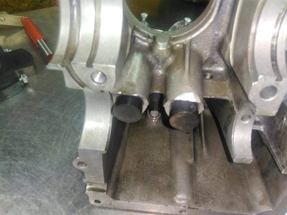
18 3. Timing camshaft crankshaft Rdequired parts : - Old crankcase 602cc - 2nd hand cylinder 602cc - 2nd hand piston 602cc (without piston rings) - 2nd hand cylinder head 602cc (without push rod tubes) - 2nd hand oilpump 602cc - 2nd hand cam follower 602cc - Spring handbrake - M5 bolt - Long M7 bolt - Multitool VGS Step 1: Mount the support(s) for the micrometer with a M5 bolt as indicated on the picture. You should drill and tap this into the crankcase. Mount the oiled cam follower with a spring and a bolt into the crankcase so you can operate the micrometer. 18
19 19


20 Step 2: Mount the camshaft and crankshaft in the right half of an old 2CV crankcase. Check the original Citroën mark. Afterwards mount the left piece. Mount together the 2 halves with at least 2 original M10 bolts (diagonally). Step 3: Mount an old cylinder and a piston without piston rings. 20


21 Step 4: Mount the cylinder head without rocker arms, but with rocker arm shafts. 21
.")


22 Step 5: Turn the crankshaft in a way that the piston is in the lowest position (BDC). Then mount the blocking pin in the location of the spark plug. Tighten the locking pin by hand. Step 6: Mount the smaller degree wheel (170mm) onto the crankshaft with the M10 bolt (included with multi tool). 22


23 Step 7: Mount an arrow (iron wire, piece of metal, ) onto the right half of the crankcase at a random location. Make sure the arrow is securely fastened. (It s possible that you might need to demount the left half afterwards, see picture). Step 8: Turn the crankshaft clockwise until the piston touches the blocking pin. Set the degree wheel to 0. Now gently tighten the M10 bolt (step 6). 23


24 Step 9: Turn the crankshaft counter clockwise until the piston touches the blocking pin again. Read the number of degrees on the grading scale. Write this down. On this photo we read 65. Divide the number of degrees by 2. In this example: 65 2 = 32.5 Loosen the nut from the M10 bolt. To release the degree wheel, you might need to tap the back of it a few times. Turn the degree wheel further to the left until it shows Now re-tighten the degree wheel. Turn the degree wheel so that the crankshaft rotates with it and the piston touches the blocking pin again. The disk should now display 32.5, or the number you calculated. If not, repeat the previous step until left and right are equal. 24
25 Step 10: Demount the blocking pin. Step 11: If the degree wheel shows 0), this is the exact 0-point of the engine. 25


26 Step 12: Mount the micrometer on the back of the left half of the crankcase. Step 13: Turn the crankshaft until the micrometer is fully depressed (highest point of the camshaft). Then turn the micrometer to 0. Turn the crankshaft left and right one more time to ensure that you are at the highest point of the camshaft. 26


27 Step 14: Turn the crankshaft counter clockwise until the large arrow of the micrometer reaches 50 or is turned half a turn. Turn the crankshaft clockwise until the micrometer is at 90. Now read the number of degrees on the degree wheel (normally this value is between 90 and 105, if not: check all previous steps). In our example this is 98. Note down this value of 98 27

28 Step 15: Now turn the crankshaft clockwise until the large arrow on the micrometer is at 0 and again at exactly 90. (If you turn too far, first turn backwards enough to eliminate the backlash). Now read the number of degrees on the degree wheel. In our example this is 125 Add up the quoted degrees. In our example: = 223 Divide the obtained value by = Every camshaft supplier gives the ideal value (lobe center line) for the optimal functioning of the camshaft. Citroën recommended 108 for a standard 2CV camshaft (Original camshaft only). We calculate with the ideal value = = 1.75 To obtain 108 we have to put the camshaft gear 1.75 earlier. 28

29 Step 16: Disassemble the left half of the crankcase. Remove the camshaft from the crankcase. Leave the arrow on the crankcase. Leave the crankshaft in the crankcase. Do NOT disassemble the cylinder, piston and cylinder head! You only need the camshaft. Look at the manual replace the camshaft bearing. Carry out steps 1 through to 4. Instead of setting the degree wheel to 0, set the degree wheel to Remember that you have to put the 0 to the left of the arrow to advance the timing. The 0 on the right means to retard the timing! In our example, we have to advance the timing by 3.5. We have calculated that we need to set 1.75 for this on the degree wheel. 29

30 Step 17: Look at the manual replace the camshaft bearing. Execute steps 5 through to 9. Take the spocket wheel with the degree wheel from the gas burner. Place this in the camshaft support until the degree wheel shows 0. Remember that you only have 5 to 10 seconds! Try to do this as accuratly as possible. We work with a tolerance of 0.25 on the crankshaft. After the sprocket wheel has cooled down, disassemble the degree wheel and remount the springs. camshaft bearing (step 11). Step 18: Fit the camshaft back into the crankcase using the original marks. Remeasure (steps 13 to 15). Your result should now be 108. A slight difference is possible. If you are between and you can be proud of yourself! Reinstall the nose onto the camshaft as described in the manual Replace the 30
31 Example diagram Camshaft: 4. Search for the BDC-of the engine See manual timing camshaft - crankshaft steps 1 to 11. This way you define the exact 0-point of the engine. You need this point, for example, if you want to mount an electronic ignition on a visa-engine. 31


32 5. Check / measure valve lift See manual Timing camshaft-crankshaft steps 12 to 13. The difference with the Timing camshaft-crankshaft is that you first have to find the lowest point of the camshaft. Next, at the micrometer you have to set both the small and the big arrow to 0. Turn the crankshaft until the micrometer indicates the maximum value. You can use this for all 4 cams. This way you have perfect control over the condition of your camshaft. best to check this cam first. An original 2CV6 camshaft has a 6.15mm lift. The cam closest to the gear is usually the most worn out. It is 32

33 Check your supplier's datasheet and compare (see example) 33
ENGINE CONTENTS ENGINE REMOVAL AND REINSTALLATION 3-1 ENGINE REMOVAL 3-1 ENGINE REINSTALLATION 3-5 ENGINE DISASSEMBLY 3-7 STARTER MOTER 3-7
 ENGINE CONTENTS ENGINE REMOVAL AND REINSTALLATION 3- ENGINE REMOVAL 3- ENGINE REINSTALLATION 3-5 ENGINE DISASSEMBLY 3-7 3 STARTER MOTER 3-7 CYLINDER HEAD COVER 3-8 PISTON 3- MAGNETO COVER 3-3 MAGNETO ROTOR
installation manual 123\TUNE+-2CV
 installation manual 123\TUNE+-2CV Installation Instructions The 123\TUNE+-2CV is designed for the stock (BLACK) 2CV-coil STEP 1 Turn the ignition off. Remove the engine fan use a long 14 mm socket or
BOTTOM END SERVICE TOOLS SERVICE PRODUCTS ENGINE, CVT AND GEARBOX Subsection 10 (BOTTOM END)
") BOTTOM END SERVICE TOOLS Description Part Number Page CRANKCASE SUPPORT MAG/PTO... 529 036 031... 151 CRANKSHAFT LOCKING BOLT... 529 035 617... 154 DRIVE SHAFT OIL SEAL INSTALLER... 529 036 028... 143
BOTTOM END SERVICE TOOLS Description Part Number Page CRANKCASE SUPPORT MAG/PTO... 529 036 031... 151 CRANKSHAFT LOCKING BOLT... 529 035 617... 154 DRIVE SHAFT OIL SEAL INSTALLER... 529 036 028... 143
7. CYLINDER HEAD/VALVES
 7 7 7-0 SERVICE INFORMATION...7-1 CYLINDER HEAD DISASSEMBLY...7-7 TROUBLESHOOTING...7-2 CYLINDER HEAD ASSEMBLY...7-8 CAMSHAFT REMOVAL...7-3 CYLINDER HEAD INSTALLATION...7-8 CYLINDER HEAD REMOVAL...7-5
ENGINE CONTENTS ENGINE REMOVAL AND REINSTALLATION 3-1 ENGINE REMOVAL 3-1 ENGINE REINSTALLATION 3-5 ENGINE DISASSEMBLY 3-7 STARTER MOTER 3-7
 ENGINE CONTENTS ENGINE REMOVAL AND REINSTALLATION 3-1 ENGINE REMOVAL 3-1 ENGINE REINSTALLATION 3-5 ENGINE DISASSEMBLY 3-7 3 STARTER MOTER 3-7 CYLINDER HEAD COVER 3-8 PISTON 3-12 MAGNETO COVER 3-13 MAGNETO
ENGINE CONTENTS CAUTION
 ENGINE CONTENTS ENGINE REMOVAL AND REINSTALLATION 3- ENGINE REMOVAL 3- ENGINE REINSTALLATION 3-7 ENGINE DISASSEMBLY 3-9 STARTER MOTER 3-9 THERMOSTAT 3-9 ND AIR VALVE 3-0 CYLINDER HEAD COVER 3-0 PISTON
installation manual 123\2CV, 123\UNI & 123\EVO
 installation manual 123\2CV, 123\UNI & 123\EVO old situation with points new situation with 123\2CV Installation Instructions All 123ignition\2CV modules are designed for the stock (black) 2CV-coil. Previous
SPECIFICATIONS TEST AND ADJUSTMENT SPECIFICATIONS SPECIFICATIONS ENGINE FD620D, K SERIES
 ENGINE FD620D, K SERIES SPECIFICATIONS SPECIFICATIONS TEST AND ADJUSTMENT SPECIFICATIONS Engine Oil Pressure Sensor Activates............................... 98 kpa (14.2 psi) Oil Pressure While Cranking
N63 Valve Stem Seal Tool Kit Part #: AGA-N63-VSK-K
 N63 Valve Stem Seal Tool Kit Part #: AGA-N63-VSK-K Problem: Your BMW is smoking due to bad valve stem seals. Old valve stem seals harden over time and no longer provide a proper seal between the seal and
ENG V-BELT AUTOMATIC TRANSMISSION Tighten: primary sheave nut 1
 V-BELT AUTOMATIC TRANSMISSION 2 1 5. Tighten: primary sheave nut 1 Nm (16.0 m kg, 115 ft lb) T R.. 160 CAUTION: Before tightening the nut to remount the primary sheave, make sure that the serrations of
The Multi-Fuel Timing Conversion Kit Installation & Setup Instructions
 The Multi-Fuel Timing Conversion Kit Installation & Setup Instructions 1. Remove the flywheel shroud from engine, uninstall the recoil pull start unit from the shroud. 2. Remove the valve cover and the
Maintenance Instructions
 General Note These instructions contain information common to more than one model of Bevel Gear Drive. To simplify reading, similar models have been grouped as follows: GROUP 1 Models 11, 0, 1,, (illustrated),,
installation manual 123\2CV, 123\UNI & 123\EVO
 installation manual 123\2CV, 123\UNI & 123\EVO old situation with points Installation Instructions All 123ignition\2CV modules are designed for the stock (black) 2CV-coil but are also compatible with high
1. Remove the crankshaft pulley, engine coolant pump pulley and drive belt. 2. Remove the timing belt cover.
 DISASSEMBLY 1. Remove the crankshaft pulley, engine coolant pump pulley and drive belt. 2. Remove the timing belt cover. 3. Turn the crankshaft clockwise and align the timing marks so as to bring the No.
Contents Essential Information & Using This Book... 4
 Contents Essential Information & Using This Book... 4 Introduction & High-Performance Engine Basics 6 Chapter 1: Buying A Used Stock Engine... 11 Checking engine condition... 12 Summary of checks... 15
ENGINE TUNE-UP INSPECTION OF ENGINE COOLANT INSPECTION OF ENGINE OIL INSPECTION OF BATTERY. INSPECTION OF AIR FILTER (Paper Filter Type)
") ENGINE MECHANICAL - Engine Tune-Up EM-17 ENGINE TUNE-UP INSPECTION OF ENGINE COOLANT (See steps 1 and 2 on page CO-4) INSPECTION OF ENGINE OIL (See steps 1 and 2 on page LU-5) INSPECTION OF BATTERY (See
ENGINE MECHANICAL - Engine Tune-Up EM-17 ENGINE TUNE-UP INSPECTION OF ENGINE COOLANT (See steps 1 and 2 on page CO-4) INSPECTION OF ENGINE OIL (See steps 1 and 2 on page LU-5) INSPECTION OF BATTERY (See
Ignition Timing - Honda 180-Degree Twins
 Ignition Timing - Honda 180-Degree Twins First thing to do is make a quick test light - I used a 12 volt indicator bulb from a speedo. Test leads with alligator clips make hookup easy... The point plate
This is a guide to assist you adjust the valve clearance on a 2l V6 MIVEC engine found in a Mitsubishi FTO GPX
 Adjusting the valve clearance on a 2L V6 FTO engine This is a guide to assist you adjust the valve clearance on a 2l V6 MIVEC engine found in a Mitsubishi FTO GPX Disclaimer: This guide is to assist you
A-PDF Split DEMO : Purchase from to remove the watermark
 5-18 FUEL AND LUBRICATION SYSTEM A-PDF Split DEMO : Purchase from www.a-pdf.com to remove the watermark Use a % size drill bit with a drill-stop to remove the pilot screw plug. Set the drill-stop 6 mm
KIT TOOLS MANUAL For Engine Assembly
 KIT TOOLS MANUAL For Engine Assembly Preface This manual provides motorcycle teams with clear information on a line of tools that simplify basic tuning. We believe that these tools make engine tuning accessible
Service and Repair SERVICE POINTS OF REMOVAL. Select Vehicle New TSBs Technician's Reference Mitsubishi 3000GT V6-2972cc 3.
 1 of 12 5/4/2008 10:31 PM Home Account Contact ALLDATA Log Out Help METRO TOYOTA Select Vehicle New TSBs Technician's Reference 1992 Mitsubishi 3000GT V6-2972cc 3.0L DOHC Vehicle Level Engine, Cooling
TSI Date Group No. Supp. Page
 Volvo Trucks North America, Inc. Greensboro, NC USA This TSI Service Bulletin and others in Groups 21 and 33 replace TSI Service Manual 210 600, Basic Engine, D12, D12A, D12B, D12C (8.2000), publication
SPECIFICATIONS TEST AND ADJUSTMENT SPECIFICATIONS SPECIFICATIONS ENGINE FD620D, K SERIES
 TEST AND ADJUSTMENT Engine Oil Pressure Sensor Activates............................... 98 kpa (14.2 psi) Oil Pressure While Cranking (Minimum).......................... 28 kpa (4 psi) Oil Pressure.....................................
2006 MINI Cooper ENGINE Engine - Technical Data - Cooper (W10) & Cooper S (W11) Engine - Technical Data - Cooper (W10) & Cooper S (W11)
 & Cooper S (W11) Engine - Technical Data - Cooper (W10) & Cooper S (W11)") ENGINE, GENERAL 11 00 ENGINE IN GENERAL 2002-08 ENGINE Engine - Technical Data - Cooper (W10) & Cooper S (W11) ENGINE IN GENERAL Cylinder 4 Bore mm 77 (3.03) Stroke mm 85.8 (3.377) Effective displacement
ENGINE, GENERAL 11 00 ENGINE IN GENERAL 2002-08 ENGINE Engine - Technical Data - Cooper (W10) & Cooper S (W11) ENGINE IN GENERAL Cylinder 4 Bore mm 77 (3.03) Stroke mm 85.8 (3.377) Effective displacement
Manual for the Dragonfly tattoo machine rev.2
 Manual for the Dragonfly tattoo machine rev.2 1 Introduction We are proud to present the Dragonfly tattoo machine. Designed with the tattoo artist in focus and manufactured with the highest quality materials
ADJUSTING VALVE CLEARANCE
 ADJUSTING VALVE CLEARANCE ADJUSTING VALVE CLEARANCE a Adjusting instrument for valve clearance 4. While the No. 1 cylinder is at the compression top dead center, adjust the valve clearances marked with
OVERHAUL 1. REMOVE OIL FILLER CAP SUB ASSY. 2. REMOVE OIL FILLER CAP GASKET (a) Using a screwdriver, remove the gasket from the oil filter cap.
 Using a screwdriver, remove the gasket from the oil filter cap.") 14218 ENGINE MECHANICAL PARTIAL ENGINE ASSY (2ZZGE) OVERHAUL 1. REMOVE OIL FILLER CAP SUBASSY 140R901 2. REMOVE OIL FILLER CAP GASKET (a) Using a screwdriver, remove the gasket from the oil filter cap.
14218 ENGINE MECHANICAL PARTIAL ENGINE ASSY (2ZZGE) OVERHAUL 1. REMOVE OIL FILLER CAP SUBASSY 140R901 2. REMOVE OIL FILLER CAP GASKET (a) Using a screwdriver, remove the gasket from the oil filter cap.
CYLINDER HEAD OVERHAUL
 ENGINE OVERHAUL PROCEDURES - GENERAL INFORMATION -2011 Mercedes-... Page 1 of 20 CYLINDER HEAD OVERHAUL * PLEASE READ THIS FIRST * Examples used in this article are general in nature and do not necessarily
Suzuki GS1000G fork seal replacement
 Suzuki GS1000G fork seal replacement Before you start you require: 1) To read workshop service manual for your model 2) Socket allen key M8 3) Torque wrench 4) Special tool to hold inner, make your own,
10. CRANKCASE/CRANKSHAFT/TRANS- MISSION SYSTEM/STARTER SPINDLE CK
 10 10 10-0 SERVICE INFORMATION... 10-1 STARTER SPINDLE... 10-6 TROUBLESHOOTING... 10-2 CRANKSHAFT... 10-8 CRANKCASE REMOVAL... 10-3 CRANKCASE INSTALLATION... 10-10 TRANSMISSION SYSTEM... 10-3 SERVICE INFORMATION
Roller Camshaft Installation
 Installation Instructions Roller Camshaft Installation For more information, see www.cranecams.com READ CAREFULLY AND COMPLETELY BEFORE INSTALLATION Prior to installation, immerse lifters in a premium
460cc Do-It-Yourself Assembly Guide
 2995 Coleman St North Las Vegas, NV 89032 702-530-7753 702-643-7517 FAX VegasCarts.com 460cc Do-It-Yourself Assembly Guide *DIY Engines do not come with a warranty, these kits are intended for experienced
2001 Chevrolet Metro LSi ENGINES 1.3L 4-Cylinder - Metro & Firefly (Canadian) Fig. 3: Exploded View Of Timing Belt & Components (Typical)
 Fig. 3: Exploded View Of Timing Belt & Components (Typical)") Fig. 3: Exploded View Of Timing Belt & Components (Typical) Fig. 4: Aligning Timing Marks 6. Loosen the timing belt tensioner bolt and the stud. 7. After pushing up the tensioner plate completely with
Fig. 3: Exploded View Of Timing Belt & Components (Typical) Fig. 4: Aligning Timing Marks 6. Loosen the timing belt tensioner bolt and the stud. 7. After pushing up the tensioner plate completely with
Arrow Shark 2015 E-Starter V4 Owner Manual
 Arrow Shark 2015 E-Starter V4 Owner Manual The Arrow Shark E-Starter V3 has successfully been available in the market for over three years now. During that time, we have never stopped seeking ways to improve
Volkswagen New Beetle 2.0 Liter 4-cyl General, Engine (Engine Code AEG) 13 Engine-Crankshaft, Cylinder block (Page GR-13)
 13 Engine-Crankshaft, Cylinder block (Page GR-13)") 13 Engine-Crankshaft, Cylinder block (Page GR-13) Engine, disassembly and assembly 10-222 A/21 guide from 10-222 A support tool, modifying Ribbed belt, removing and installing Semi-automatic toothed belt
13 Engine-Crankshaft, Cylinder block (Page GR-13) Engine, disassembly and assembly 10-222 A/21 guide from 10-222 A support tool, modifying Ribbed belt, removing and installing Semi-automatic toothed belt
TSS Fit Kit Installation Instructions Timbersled Snow Bike System
 TSS Fit Kit Installation Instructions Timbersled Snow Bike System Information needed before you start: Read the entire installation instructions before starting. The instruction sheet is universal for
Figure 1 Factory G50 update and old Shift Fork Shaft
 911 Clutch Job So you have one of the best 911s there is, a 87-89 G50 Porsche. However, after many years of service, it is time for a clutch. Maybe, the rubber clutch disc has failed, or the clutch is
CLASSIC MOTORCYCLE RESTORATION
 2.6 A good hammer helps with tasks such as knocking out rusted-in spindles, bushes, and shafts, gently easing in or out bolts or bushes, or gently tapping the end of the screwdriver to help split mating
Though Indian s 111-cubic-inch engine delivers a
 TECH by Chris Maida Andrews Indian 111 Camshafts Part I: Removing the cams from the camshaft compartment Tools Needed Red Loctite Clean rags 6mm Allen 5/64" Allen 3/32" punch External circlip pliers Needlenose
Prerequisites: Shop Manual (recommended) pages 3-9 through 3-13.
 pages 3-9 through 3-13.") Prerequisites: Order your gaskets average about $25.00 bucks X 2 so $50.00 4NK-11193-00-00 Obtain a shim kit (Should have several 265 and 270s) (Some dealers will exchange) Obtain a Valve Bucket Tool YM-33961
Prerequisites: Order your gaskets average about $25.00 bucks X 2 so $50.00 4NK-11193-00-00 Obtain a shim kit (Should have several 265 and 270s) (Some dealers will exchange) Obtain a Valve Bucket Tool YM-33961
Fig. 6: Assembling Piston & Rod. NOTE: Notch must face forward Toyota Starlet CRANKSHAFT MAIN BEARINGS
 connecting rods are marked for reassembly. 3. Thoroughly clean and inspect all components. Coat pin with engine oil and heat piston to 158-176 F (70-80 C). Pin should push fit with thumb pressure through
WORKSHOP MANUAL TECHNICAL NETWORK LEADERSHIP WORKSHOP MANUAL 125 CC/150 CC 4-STROKE ENGINE
 WORKSHOP MANUAL TECHNICAL NETWORK LEADERSHIP WORKSHOP MANUAL - 5 CC/50 CC 4-STROKE ENGINE Workshop manual Technical network leadership TABLE OF CONTENTS TABLE OF CONTENTS TABLE OF CONTENTS... CHARACTERISTICS...
DrVanos.com Stage II Installation Instructions. Tool rental is available with the purchase of a vanos kit *See website for more info*
 DrVanos.com Stage II Installation Instructions Special Tools Needed: Camshaft locking tool TDC Crank pin Sprocket turning tool Tool rental is available with the purchase of a vanos kit *See website for
Porsche 928 with 16v LH-Jetronic Fuel System
 Porsche 928 with 16v LH-Jetronic Fuel System Toll-Free Tech Hot Line: 877-FOR-928M 877-367-9286 Please do not copy this manual and give copies to your friends. Our ability to bring you this supercharger
CAUTION: When aligning timing marks, always rotate engine by turning the crankshaft. Failure to do so will result in valve and/or piston damage.
 REMOVAL Timing Chain 1. Disconnect negative battery cable. 2. Drain cooling system. 3. Remove upper intake manifold. 4. Remove cylinder head covers, crankshaft vibration damper, and timing chain cover.
CRANKSHAFT & MAIN BEARINGS
 CRANKSHAFT & MAIN BEARINGS * PLEASE READ THIS FIRST * REMOVAL Ensure all main bearing caps are marked for location on cylinder block. Some main bearing caps have an arrow stamped on them. The arrow must
Rekluse Motor Sports. The z-start Clutch GAS GAS. 200, 250, and strokes. 400 and strokes
 Rekluse Motor Sports The z-start Clutch GAS GAS 200, 250, and 300 2-strokes 400 and 450 4-strokes Installation Guide Copyright 2002-2004 Rekluse Motor Sports z-start Revision 3.000 RMS100 Gas Gas z-start
ENGINE MECHANICAL > VALVE CLEARANCE INSPECTION > 2.5L >
 Print 2003 Subaru Forester 2.5L Eng X ENGINE CONTROLS - ON-VEHICLE ADJUSTMENTS ENGINE MECHANICAL > VALVE CLEARANCE INSPECTION > 2.5L > 1. Set the vehicle onto the lift. 2. Lift-up the vehicle. 3. Remove
 www.odometergears.com Mercedes-Benz Mechanical Odometer Repair This how to can be used for all mechanical repairs as the only difference will be the removal of the instrument cluster. http://www.dieselgiant.com/repairyourodometer.htm
EZ-Glide Wheels Installation Patent Pending Revised 8/23/2011
 EZ-Glide Wheels Installation Patent Pending Revised 8/23/2011 Questions: Lakeside Quilt Co. Jack Boersma Toll Free (888) 361-4806 www.lovetoquilt.com Cell (406) 270-4715 sales@lovetoquilt.com Toll Free
OVERHAUL MANUAL 28/09/05 mod. A 1 MAN-044 ING
 OVERHAUL MANUAL 28/09/05 mod. A 1 INDEX Page 1. - PARILLA X30 125cc RL TaG ENGINE DISASSEMBY 1 2. - CRANKSHAFT DISASSEMBLY/ ASSEMBLY 10 2.1- CRANKSHAFT DISASSEMBLY 10 2.2- CRANKSHAFT ASSEMBLY 12 3. - PARILLA
ENGINE MECHANICAL EM SECTION CONTENTS
 ENGINE MECHANICAL EM SECTION CONTENTS INTAKE MANIFOLD...EM-2 Component Parts Location...EM-2 Removal and Installation...EM-3 Inspection...EM-3 EXHAUST MANIFOLD...EM-4 Component Parts Location...EM-4 Removal
I. TWO-STROKE MECHANICAL EN- GINE PARTS
 I. TWO-STROKE MECHANICAL EN- GINE PARTS 1. UNIBLOCK ENGINES (AV520-600-750-125) a) INTRODUCTION Fig. 1 shows the short block. Fig. 2 shows an exploded view of the engine. As may be seen the momoblock is
EGR Performance Brakes Assembly Instructions DODGE DANA 70 '87 - '93 (Will not fit stock sized dual rear wheels)
") EGR Performance Brakes Assembly Instructions DODGE DANA 70 '87 - '93 (Will not fit stock sized dual rear wheels) Got Brakes? Parts List (2) Vented Rotors (2) Multi hole Cable Mount & L Brkt (2) Axle Tube
EGR Performance Brakes Assembly Instructions DODGE DANA 70 '87 - '93 (Will not fit stock sized dual rear wheels) Got Brakes? Parts List (2) Vented Rotors (2) Multi hole Cable Mount & L Brkt (2) Axle Tube
AmTryke Adult Recumbent Model JT2000 #50-FC-2000
 AmTryke Adult Recumbent Model JT2000 #50-FC-2000 TOOLS Needed for Assembly 5 mm Allen Wrench 8 mm Socket or Wrench 10 mm Socket or Wrench 14 mm Socket or Wrench 15 mm Socket or Wrench 22 mm Socket or Adjustable
Mixer Discharge Door Adjustment on models; 30, 42, 54, 81, 108, 135 mixers.
 Knowledge Base Article Type: Instructions Mixer Discharge Door Adjustment on models; 30, 42, 54, 81, 108, 135 mixers. Description: Instructions on How to set-up and adjust the discharge door on Columbia
ENGINE REMOVAL AND REINSTALLATION 3-1 ENGINE REMOVAL 3-1 ENGINE REINSTALLATION
 ENGINE CONTENTS ENGINE REMOVAL AND REINSTALLATION 3-1 ENGINE REMOVAL 3-1 ENGINE REINSTALLATION 3-5 ENGINE DISASSEMBLY 3-6 ENGINE COMPONENTS INSPECTION AND SERVICING 3-15 BEARINGS 3-15 OIL SEALS 3-15 CRANKSHAFT
PORSCHE V TO 32V CAM GEAR CONVERSION INSTRUCTIONS. For all 16V engines: USA 78-84, Euro
 PORSCHE 928 16V TO 32V CAM GEAR CONVERSION INSTRUCTIONS For all 16V engines: USA 78-84, Euro 77-86 2.0 cams@mrtubby.net Required parts not included in kit (2) HTD 32V cam gears - sprocket 928.105.530.01
Backwater Performance Systems Large Vanguard Mikuni Twin Carburetor Kit
 Backwater Performance Systems Large Vanguard Mikuni Twin Carburetor Kit 1. Throttle Cable Twin (CKC-41) 2. Carburetor VM30mm (CKC-40) 3. Loctite 242.5mL (A-210) 4. Air Cleaner Filter 6000 (EC-86) 5. Rev
REEDSTER 125cc. versions: F1 - F2 - F3 - F4 OVERHAULING MANUAL
 REEDSTER 125cc versions: F1 - F2 - F3 - F4 OVERHAULING MANUAL 07/11/07 21/01/2009 1 INDEX Page 1. - REEDSTER 125cc ENGINE DISASSEMBLY 1 2. - CRANKSHAFT DISASSEMBLY / ASSEMBLY 13 2.1 - CRANKSHAFT DISASSEMBLY
BRAKE E
 8-1 GENERAL...8-2 SPECIFICATIONS...8-6 COMPONENTS...8-7 FRONT BRAKE...8-12 DISASSEMBLY INSPECTION REASSEMBLY (Pn1, Cu2 3 TON SERIES)...8-12 DISASSEMBLY INSPECTION REASSEMBLY (Pn2 3 TON SERIES)...8-17 BRAKE
ENGINE CONTENTS ENGINE REMOVAL AND REINSTALLATION 3-1 ENGINE REMOVAL 3-1 ENGINE REINSTALLATION 3-6 ENGINE DISASSEMBLY 3-8 STARTER MOTER 3-8
 ENGINE CONTENTS ENGINE REMOVAL AND REINSTALLATION 3-1 ENGINE REMOVAL 3-1 ENGINE REINSTALLATION 3-6 ENGINE DISASSEMBLY 3-8 3 STARTER MOTER 3-8 CYLINDER HEAD COVER 3-9 PISTON 3-13 MAGNETO COVER 3-14 MAGNETO
Slide the billet aluminum cap over the bushing and secure with the 3/8-16 x 2 1/2 socket head allen and locknuts provided.
 Slide the billet aluminum cap over the bushing and secure with the 3/8-16 x 2 1/2 socket head allen and locknuts provided. Put the urethane bushings into the upper antiroll-bar-link eyebolt. Coat the bushings
88cc Big Bore Kit Install Instructions
 88cc Big Bore Kit Install Instructions Before installing a big bore kit, you should first install a high volume oil pump. A high volume oil pump will deliver up to 300% more oil to your top end which will
1 August Dodge Adjustable Track bar with Relocation Bracket 1
 1 August 2017 1032011-1994-2002 Dodge Adjustable Track bar with Relocation Bracket 1 DOWNLOAD ENHANCED INSTALL MANUALS AT BD Adjustable Track Bar w/bracket Dodge 2500-3500 4WD Models 1994-2002 Dodge 1500
4TH GEN SEATS IN A 3RD GEN TRUCK
 4TH GEN SEATS IN A 3RD GEN TRUCK by Flopster843 02 Oct 2016 If you drive a 3rd generation Dodge Ram truck, I am sure you have discovered that the OEM seats are not the greatest (Figure 1.) They are extremely
2002 Honda Passport LX
 Fig. 151: Removing Piston Pin 11. Piston (10) Page 130 2005 Mitchell Repair Information Company, LLC. 12. Connecting rod (11) INSPECTION AND REPAIR Pistons Carefully clean away all the carbon adhering
15.Timing Belt Assembly
 MECHANICAL 15.Timing Belt Assembly A: REMOVAL 1. TIMING BELT 1) Remove the V-belt. 2) Remove the crank pulley.
928 Motorsports Supercharger Installation Copyright 2007, 928 Motorsports, LLC All Rights Reserved
 For Porsche 928 equipped with K-Jetronic (CIS) Fuel System Toll-Free Tech Hot Line: 877-FOR-928M 877-367-9286 Please do not copy this manual and give copies to your friends. Our ability to bring you this
1998 Saab 900 SE ENGINES Saab 2.0L & 2.3L 4-Cylinder
 Removal & Installation See VALVE SPRINGS under CYLINDER HEAD under OVERHAUL. CAMSHAFT Removal 1. Rotate crankshaft until "0" mark on flywheel aligns with timing mark on flywheel cover. Remove inspection
Sherco Setup and Lubrication Guide
 Sherco Setup and This guide is designed to provide the Sherco owner with instructions on how to: Set up a new bike Clean and re-oil the air filter Change the transmission oil Change the fork oil Repack
Next, chase the threads in the lower A-arm mounts with the 5/8-18 tap and blowout any remaining particles.
 Next, chase the threads in the lower A-arm mounts with the 5/8-18 tap and blowout any remaining particles. Now, apply some anti-seize to the threads of the pivot stud. Also put anti-seize inside the bore
Service Manual. LT-5 Lawn Tractor
 Service Manual LT-5 Lawn Tractor NOTE: These materials are for use by trained technicians who are experienced in the service and repair of outdoor power equipment of the kind described in this publication,
1996+ Yamaha G16 / G22 Yamaha G29/YDRA Drive
 Vegas Carts & Performance 2995 Coleman St North Las Vegas, NV 89032 702-530-7753 VegasCarts.com 625cc Big Block Installation Instructions 1996+ Yamaha G16 / G22 Yamaha G29/YDRA Drive Revised 8/6/2018 1
Commander SUSPENSION SYSTEM INSTALLATION INSTRUCTIONS
 PARTS INCLUDED: 2 - FRONT UPPER A-ARMS 2 - FRONT LOWER A-ARMS 4 - COTTER PINS 2-12MM JAM NUTS 2 - TIE ROD EXTENDERS 8- FLANGED DELRON BUSHINGS 4- DELRON CASTER SPACERS 6 - GREASE FITTINGS 3 - BEARING REMOVAL
Precision Degree Wheel Kit
 555-81621 Precision Degree Wheel Kit Instruction Booklet Instructions for 81621 Camshaft Degree Kit Thank you for purchasing the Jegs Camshaft Degree Kit. Please follow these detailed instructions to properly
DISSECTION OF AN INTERNAL COMBUSTION ENGINE
 DISSECTION OF AN INTERNAL COMBUSTION ENGINE Purpose: The purpose of this dissection is to familiarize you with the construction and operation of a Briggs & Stratton model 80232 one cylinder, four-stroke,
5-3. ENGINE BOTTOM END
 BOTTOM END ENGINE DRIVE SHAFT 5-3-1 CRANKCASE Remover: 560012 Installer: 560011 Remover: 560014 Installer: 560013 CRANKSHAFT 5-3-2 WATER PUMP, OIL PUMP Installer: 560025 Remover: 560024 Installer: 560003
All DOHC Honda CB750s, CB900s and CB1100s
 Installation Instructions for: V &H Racing Curved Guide & AHM Cam Chain Tensioner All DOHC Honda CB750s, CB900s and CB1100s Models C, F and R Page 1 Introduction. Thank you for your purchase of the Vince
Tech Talk. Timing Belt 6VD1/6VE1
 Holden DOHC V6 Frontera 6VD1 3.2L 1999 2004 Jackaroo 6VE1 3.5L 1998 2004 Rodeo TF 6VD1 3.2L 1998 2003 Rodeo RA 6VE1 3.5L 2003 2005 Important: Read through all the instructions before proceeding with the
13 March F Dodge Adjustable Track bar with Relocation Bracket (I-00201) 1
 1") 13 March 2014 1032011-F 1994-2002 Dodge Adjustable Track bar with Relocation Bracket (I-00201) 1 BD Adjustable Track Bar w/bracket Dodge 2500-3500 4WD Models 1994-2002 P/N# 1032011-F UPLEASE READ ALL INSTRUCTIONS
13 March 2014 1032011-F 1994-2002 Dodge Adjustable Track bar with Relocation Bracket (I-00201) 1 BD Adjustable Track Bar w/bracket Dodge 2500-3500 4WD Models 1994-2002 P/N# 1032011-F UPLEASE READ ALL INSTRUCTIONS
Tach-Drive Distributor Reconditioning Joe Fisher PDF prepared by Dave Zuberer Link to Thread on the Corvette Forum (C1-C2)
") Tach-Drive Distributor Reconditioning Joe Fisher PDF prepared by Dave Zuberer Link to Thread on the Corvette Forum (C1-C2) I just finished two Corvette tach-drive distributors. One was a 71 small block
Tach-Drive Distributor Reconditioning Joe Fisher PDF prepared by Dave Zuberer Link to Thread on the Corvette Forum (C1-C2) I just finished two Corvette tach-drive distributors. One was a 71 small block
VALVE ADJUSTMENT. To perform a valve adjustment, the engine must be cold: minimum of 4 hours after shutoff, overnight is preferable.
 VALVE ADJUSTMENT The following instructions cover valve adjustment on nonhydraulic (solid lifter) engines. Check the specification sheet on your vehicle to establish your specific engine. If not available,
INSTALLATION & USER S GUIDE
 REKLUSE MOTOR SPORTS The Rekluse Core EXP Kit with Adjustable Slave Cylinder INSTALLATION & USER S GUIDE Doc ID: 191-7704A Doc Rev: 102915 OVERVIEW This kit replaces the OEM core clutch components including
Sachs shock manual. ( ) 2 & 4 Stroke RR Enduro. ( ) RS Dual Sport
 2 & 4 Stroke RR Enduro. ( ) RS Dual Sport") Sachs shock manual (2013 2015) 2 & 4 Stroke RR Enduro (2014-2015) RS Dual Sport 1 Introduction The procedures in this manual must take place in a clean environment using professional tools and some specific,
Sachs shock manual (2013 2015) 2 & 4 Stroke RR Enduro (2014-2015) RS Dual Sport 1 Introduction The procedures in this manual must take place in a clean environment using professional tools and some specific,
Timing Belt: Service and Repair
 2000 Hyundai Sonata L4-2.4L Page 1 Timing Belt: Service and Repair REMOVAL 1. Remove the crankshaft pulley, engine coolant pump pulley and drive belt. 2. Remove the timing belt cover. 2000 Hyundai Sonata
Moped Hospital Racing. Installation of performance parts MANUAL. Tecnigas Extreme Super 9
 Moped Hospital Racing Installation of performance parts MANUAL Tecnigas Extreme Super 9 Page 2 These pages are to help the shop/person installing the parts that we sell. It is a general explanation of
GruvenParts.com BRASS GM Power Folding Mirror Gear Replacement Instructions. Updated 8/25/2017 Additional Pictures / Tips Posted!
 Page 1 GruvenParts.com BRASS GM Power Folding Mirror Gear Replacement Instructions Updated 8/25/2017 Additional Pictures / Tips Posted! ** Latest Design is uses an ALL BRASS SPUR GEAR!!! ** ** If you don
Remove Air Cleaner Cover and. Filter
 Remove Air Cleaner Cover and Inspect paper filter for tears Foam pre-cleaner is washable if equipped Replace if necessary Filter Remove Trim Panel Pull throttle lever knob off Remove 3, 8mm screws Remove
MAINTENANCE PROCEDURE FOR MK17
 MAINTENANCE PROCEDURE FOR MK17 MK17 25. juli 2005-1/5 MAINTENANCE PROCEDURE FOR MK 17 1ST STAGE WARNING: this maintenance procedure is only for appointed Scubapro technicians that followed a complete course
PORSCHE V r Valve Timing Instructions. Copyright 2009 Written by Mike Frye Edited my Adam G.
 PORSCHE 928 32V r Valve Timing Instructions Copyright 2009 Written by Mike Frye Edited my Adam G. Sections: Overview.3 Disclaimer/warnings/things to watch for 4 Terms and naming conventions used in this
Rekluse Motor Sports. The z-start Clutch. Cannondale
 Rekluse Motor Sports The z-start Clutch Cannondale Installation Guide Copyright 2002-2004 Rekluse Motor Sports z-start Revision 3.000 RMS105 Cannondale 191-205 Manual Revision: 091304 Rekluse Motor Sports,
Engine Dismantle and Assemble ( )
") Engine Dismantle and Assemble (21 134 8) Special Tools 15-030A Universal flange-holding wrench 21147 21-147 Vibration damper remover 15030A 16-067 Locator for clutch disc 21-167 Wrench for cylinder head
Engine Dismantle and Assemble (21 134 8) Special Tools 15-030A Universal flange-holding wrench 21147 21-147 Vibration damper remover 15030A 16-067 Locator for clutch disc 21-167 Wrench for cylinder head
Rebuilding the HE-120 Redrive
 Rebuilding the HE-120 Redrive Rick Cavallaro Disclaimer: I am NOT an expert mechanic. If something looks or sounds wrong in these directions, it probably is. I d be happy to receive any tips or feedback
Installation Instructions
 Part Number: 10.109.01.109 Description: AUTOTECH Sport 270 Hydraulic Camshaft Note: If the job seems to be beyond your abilities, we recommend that you refer this installation to a qualified mechanic.
X-Brake Fitting Instructions See Appendix for fitting to Range Rover,Discovery and PTO vehicles + Upgrade kit
 X-Eng is a division of Foundry 4x4 Limited The Old Bakery, Rear of Vale Terrace, Tredegar, Gwent. NP22 4HT X-Brake Fitting Instructions See Appendix for fitting to Range Rover,Discovery and PTO vehicles
Before performing any on-vehicle adjustments to fuel or ignition systems, ensure engine mechanical condition is okay.
 Page 1 of 11 ARTICLE BEGINNING INTRODUCTION Introduction information not applicable. ENGINE MECHANICAL Before performing any on-vehicle adjustments to fuel or ignition systems, ensure engine mechanical
INSTALLATION & USER S GUIDE
 REKLUSE MOTOR SPORTS The Rekluse Core EXP Kit for Kawasaki KX80/85/100 OVERVIEW INSTALLATION & USER S GUIDE Doc ID: 191-7742A Doc Rev: 073015 This kit replaces the OEM core clutch components including
Seadoo Supercharger Removal Guide RXP
 Seadoo Supercharger Removal Guide RXP RXT, RXT X, RXP X and GTX models are very similar and Removal and Installation is similar. The Ceramic washers installed by the OE manufacturer do not completely disintegrate
Fig Variable Speed Valve Parts
 5 DISASSEMBLY OF VARIABLE SPEED CONTROL VALVE (Seal Replacement with Control Valve in the Bobcat). Remove seat and seat plate (Fig. ).. Remove variable speed control lever linkage rod. 3. Remove temperature