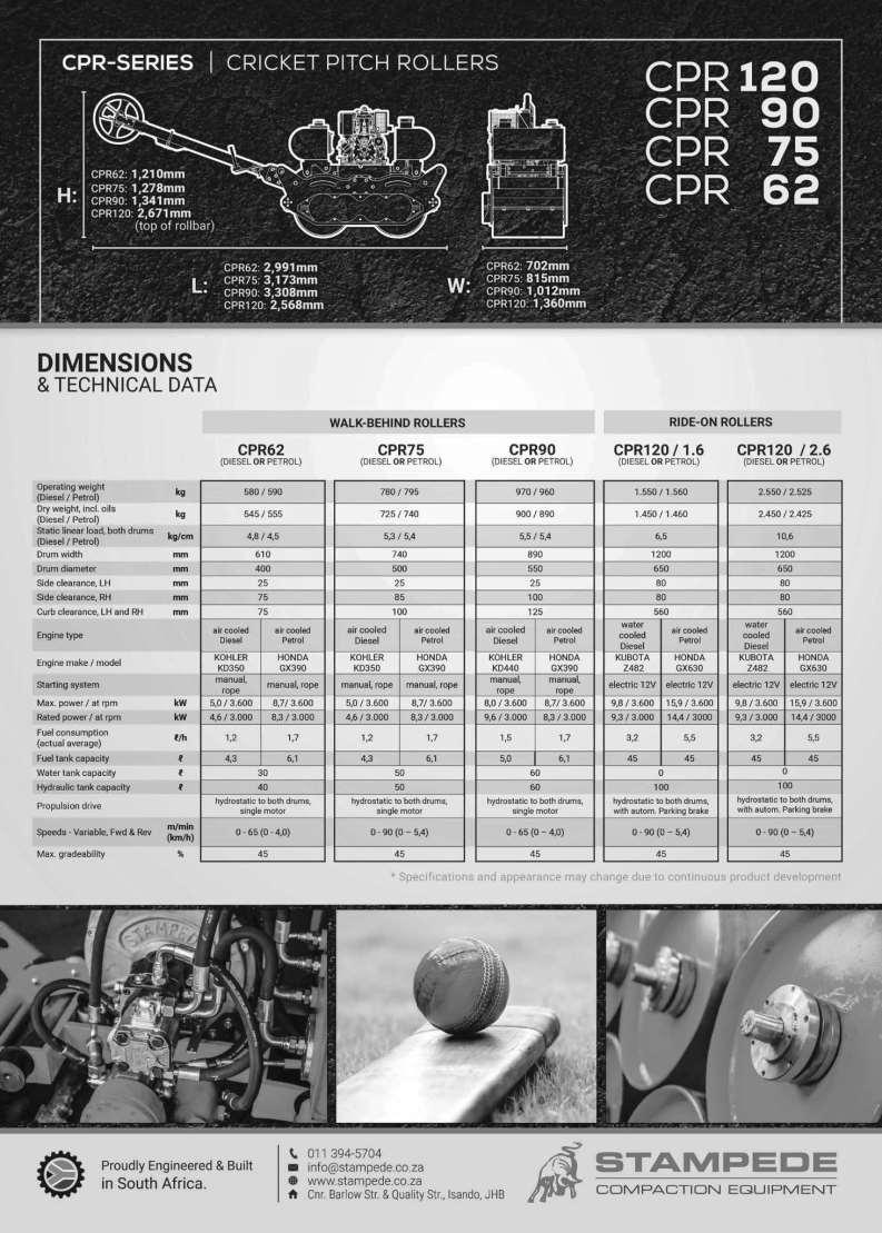
CPR-series (Cricket Pitch Roller) Ride-On ROLLERS
|
|
|
- Julius Whitehead
- 5 years ago
- Views:
Transcription
1 CPR-series (Cricket Pitch Roller) Ride-On ROLLERS Model: CPR Version: Feb Page1
2 INDEX to pages SECTION 1 GETTING TO KNOW YOUR MACHINE & OPERATING INSTRUCTIONS 1. Safety 1. Foreword and Basic Overview of the machine Page Basic description and intended use of the machine Page 5 3. Limitations of intended use of the machine Page 5 4. Lay-out of Controls Page Safety: Basics and requirements for machine operator Page 8 6. Lifting and tying down the machine Page 9 2. Operation of the machine 1. Starting and stopping of the engine Page Moving machine forward / backwards Page Selecting the HIGH or LOW speed range Page Tips for getting best compaction results 1. General Hints and Tips for the operator Page Working on slopes and near embankments that can collapse Page Daily Maintenance checks / actions Page 14 SECTION 2 SERVICING SCHEDULE / INSTRUCTIONS 1. Servicing General, and Servicing the Roller Page Preparing the machine for being towed Page Servicing KUBOTA engine Page SECTION 3 ANNEXES Technical Data Page 24 Hydraulic Diagram Page 25 Notes Page 26 Page2
3 Foreword This Manual is intended to familiarize the users of STAMPEDE Ride-On Rollers with the machine, its proper and safe operation, daily maintenance requirements and will guide the customer s servicing staff through regular Servicing and adjustments as required for this machine. The information contained in this Manual is specific to current production machines at time of publication of this Manual and may be different from previous or future versions of the equipment. STAMPEDE reserves the right to make technical changes to their equipment without notice. Further details may be obtained at any time from STAMPEDE s Service Centre. Page3
4 Overview of the machine Protection Structure / Sunshade Forward / Reverse Control Lever HIGH / LOW range Selection Lever Control Station with Instrument Panel and Control Switches/Levers Lifting and tie-down Points Drive Motors Page4
5 1. Description of the machine, intended use and lay-out of the controls 1.1. Basic description of the machine The machine is a double-drum Ride-On Tandem Roller, powered by a water cooled Kubota Diesel engine. The machine s drive systems for the propulsion of the machine, as well as for its steering are hydro-static, powered by engine-mounted hydraulic pumps. Both drums are permanently driven by a hydraulic motor directly mounted on each drum. The system allows the operator to operate the machine at infinitely variable speeds in both directions. The machine s Drive system incorporates a HIGH / LOW Speed Range selection facility, which enables the machine to negotiate steep inclines and berms. The machine is equipped with an automatic Parking Brake which will mechanically prevent the machine from moving backwards or forward, as soon as the engine has stopped. As an Option the Parking Brake can also be manually engaged by depressing the red Emergency Stop Button located on the instrument panel. This procedure, however, is reserved for EMERGENCIES ONLY and must not be used for normal stopping of the engine!!! There is provision for manual release of the brake, should this be required. The machine s upper frame is isolated from the drums by Rubber Buffers. The machine is equipped with a Protection Structure / Sunroof which will protect the operator in the event of the machine falling onto its side. 1.2 Intended use of the machine The machine is intended to be used for compaction of all types of materials / surfaces occurring on Cricket Pitches. 1.3 Limitations of intended use of the machine The machine may not be used on hard surfaces such as existing asphalt, concrete, etc. Page5
 6 Warning Light: Engine Oil Pressure 3 Fuel Tank Gauge 7 Warning Light: Glow Plug active 4 Radiator")
6 1.4 Lay-out of the Controls and Instrumentation Instrument Panel The steering wheel as well as all operational controls and instrumentation are located within the field of vision and within easy reach of the operator and are described below Hour Meter 5 Warning Light: Alternator Charging 2 EMERGENCY STOP Button (Option) 6 Warning Light: Engine Oil Pressure 3 Fuel Tank Gauge 7 Warning Light: Glow Plug active 4 Radiator Coolant Temperature gauge In an EMERGENCY the Emergency Stop Button may be activated by pressing it down this will kill the engine instantly, engage the Parking Brake and will stop all functions of the machine. This procedure is reserved for EMERGENCIES ONLY and must not be used for normal stopping of the engine!!! When any one of the Warning Lights comes on during operation, STOP machine immediately and switch off the engine report problem to Supervisor / Foreman Page6
 Do not engage Pre-Heat for more than 10 seconds D A B C A B 2")
 Drive Lever Moving the Lever forward >>> machine moves FORWARD Moving the Lever backward")
 For normal operation on reasonably flat surfaces LOW range setting (2) For extra climbing power when")
7 1.4.2 Other Controls Ignition / Starter Switch The switch has 4 positions: A Ignition OFF B Ignition ON C START position D GLOW PLUG (engine pre-heating) Do not engage Pre-Heat for more than 10 seconds D A B C A B 2 Battery Disconnector Switch (Master Switch) The switch has 2 positions: A (shown) ON position B OFF position (Battery is disconnected) Drive Lever Moving the Lever forward >>> machine moves FORWARD Moving the Lever backward >>> machine moves BACKWARDS Lever in neutral >>> machine STOPS 1 2 Speed range Selector Lever HIGH range setting (1) For normal operation on reasonably flat surfaces LOW range setting (2) For extra climbing power when negotiating steep inclines Page7
 Safety 2.")
8 Articulation Lock 2 1 Transport Lock Pin Whenever the machine is loaded on a transport vehicle, insert the Locking Pin into position (1) and secure with hairpin clip pin as shown in picture When not in use store Locking Pin in position (2) Safety 2.1 Basic requirements and Do s & Don ts for the machine operator The machine must be started and operated only by suitably qualified and physically able adults who have acquainted themselves with and do understand this Manual or have been properly trained and instructed on the safe and correct operation of the machine, in line with this Manual. Operation of the machine by under aged youngsters or persons under the influence of drugs/alcohol is specifically prohibited. The operator must at all times have the Seat Belt fastened and properly tightened whenever the machine is in motion a loose Seat Belt may result in injury or death of the operator in case of an accidental fall of the machine. No passengers are allowed on the Roller at any time. Take extra care when ground conditions (condition and inclination of surface) change machine could slide unexpectedly. Be extra cautious near edges of trenches, pits or embankments, where the ground could collapse unexpectedly. Never start the engine when not seated in the driver s seat danger to be driven over by machine! Be careful when opening the bonnet there could be hot areas (exhaust, radiator, etc.) and there could be moving parts Do not leave the machine unattended with the engine running When machine needs to be parked on an incline, always place a wedge or some rocks in front of the drums Page8
9 2.2 Lifting the machine and tying it down for transport Lifting and tying-down not permitted at any other points on the machine! Always use suitable and adequately rated Lifting Gear when lifting the machine! Never stand below / near suspended loads! Page9
10 2. Operation of the machine 3.1 Starting and stopping of the engine Visual checks before starting the engine Check engine oil level (on dip stick) (if necessary top up with SAE 15W40) Check the coolant level on the radiator Check hydraulic oil level Check fuel level (Fuel Gauge) Ensure that the Drive Lever is in its NEUTRAL position Ensure that the Rotating Beacon is working (check with Ignition switched ON) Ensure that the Reverse Buzzer is functioning (move Control Lever into REVERSE with Ignition ON) Starting the engine 1.1. If fitted, ensure that the Emergency Stop button is in the OPERATING position (raised position) 1.2. Turn Master Switch into ON position 1.3. If engine is cold: Engage the Pre-Heat function, see below (max. 10 seconds) 1.4. Turn Ignition Key clockwise to start the engine the engine will accelerate to full throttle speed automatically 1.5. Check instruments / warning lights on the dashboard for any unusual readings or indications When the engine is cold it is good practice to pre-heat the engine (by engaging the Glow Plug for a few seconds before starting) and then letting the engine run for 2 3 minutes before engaging any load this will give the engine and the hydraulic oil a chance to warm up to reasonable operating temperature. Page10

11 3.1.3 Stopping the engine Turn Ignition Switch anti-clockwise to switch the engine OFF When leaving the machine or parking it, it is good practice to turn the Master Switch into the OFF position In an EMERGENCY the Emergency Stop Button may be activated by pressing it down this will kill the engine instantly, engage the Parking Brake and will stop all functions of the machine. This procedure is reserved for EMERGENCIES ONLY and must not be used for normal stopping of the engine!!! 3.2 Moving the machine forward and backwards The forward / reverse movement of the machine is controlled with the hand control lever situated on the RH side of the control station (1) 1 Pushing the lever FORWARD will make the machine move FORWARD, pushing it BACKWARDS will make the machine move BACKWARDS the further the lever is pushed, the faster the machine will move in the desired direction When changing direction, do this in a SLOW movement of the lever to allow the machine to change direction SMOOTHLY never go from fully forward into fully reverse! The Control Lever is designed as a Dead Man s Handle it will automatically return into its NEUTRAL position as soon as the operator lets go of the Lever, and the machine will automatically come to an immediate stop. 3.3 Selecting the HIGH or LOW speed range For normal operation on reasonably flat grounds, the range selector lever is to be placed in the HIGH position (1) 1 2 For negotiating of steep inclines or berms the selector lever is placed into LOW position (2). In this setting the machine will have increased (double) climbing ability but with reduced (half) propulsion speed. Page11 The selector lever should only be shifted when the machine is stationary.
12 4. Tips for getting best compaction results 4.1 General Hints and Tips for the operator Due to the delicacy of a perfect surface of the Cricket Pitch, the instructions given by the Captain / Umpire will always be final to the operator of the Cricket Pitch Roller. Below are a few general tips for correct operation of the STAMPEDE Cricket Pitch Roller. o To get good compaction results, you always need to run the machine SLOWLY as a rule-of-thumb this means about half of normal walking speed o When starting a run or when changing direction of the machine, do this gently, to avoid spinning of the rollers on the ground. Gentle movement of the Control Lever will give you smooth acceleration and deceleration of the machine o Never change direction of the machine by going from full speed in the one direction to full speed in the reverse direction. o Never do major articulation (steering) movements when the machine is stationary, this will result in a scuffing action of the drums on the surface. o Overlapping during the rolling process and number of passes will be determined by the Captain / Umpire but should then be done in a consistent method o Never run machine over hard materials, (e.g. concrete, hard asphalt, etc.) for travelling over such areas and for longer distances do this with care and do not exceed normal walking speed Page12


13 4.3 Working on slopes and near embankments that can collapse Always operate machine UP and DOWN slopes or hills never from side to side max. max. Always work your Roller TOWARDS the edge of the embankment with the operator out of the danger zone; see below Page13
14 4. Daily Maintenance checks / actions The listing below shows the routine Daily Maintenance items, which may be performed by the operator Clean the machine, in particular any build-up of soil or asphalt in the area of the drums Refuel the machine preferably this is done at the end of the shift to avoid entry of water into the fuel tank due to overnight condensation Check the engine oil level must be between the MIN and MAX marks of the dipstick, when machine is parked on level ground Check the hydraulic oil level at the sight glass on the hydraulic tank must be at least ¾ full when machine is cold Check the Airfilter element, and clean as required handle and re-install with absolute care! Check for any loose bolts or nuts, oil leaks and any unusual noises report any unusual findings to Supervisor / Foreman Every week: check Water Trap and drain water sediment, as required CLEAN MACHINES ALWAYS WORK BETTER Page14
15 1. Servicing General, and Servicing the Roller 1.1 General Due to the inherent nature of danger during the servicing / adjustments to Construction machinery, all servicing should be performed by suitably qualified persons only, and with the use of suitable tools and in appropriate locations with required facilities. Should specific details or advice be required, this should be obtained from STAMPEDE s Service Centre personnel. Service items and spare parts should always be obtained from STAMPEDE, where they are guaranteed for consistent quality and fitness for purpose. 1.2 Roller Servicing Schedule The following table lists all regular Service / Routine Adjustment items that need to be performed at the specified intervals and with the specified servicing consumables Item # Service item Service Interval Service Consumable Quantity / Spec. 1 Lubrication of the Articulation Joint 1 month EP2 grease 2 nipples 2 Lubrication of the Steering Cylinder 1 month EP2 grease 2 nipples 3 Replacement of Hydraulic Filter Element in the return-line filter 12 Part No. OMTPR100-2-GN 1 (on top of hydraulic tank) months 4 Replacement of Breather Filter Element (on top of hydraulic tank) 12 months Part No. OMTPR100-2-AB 1 5 Hydraulic oil change 24 months Hydraulic Oil grade 68-ISO *) 6 Cleaning (or replacement) of Suction 24 Part No. Strainers in hydraulic tank months RR Water Trap / Primary Fuel Filter Part No. a) Cleaning of the Water Trap 1 month KS L 1 b) replacement of filter in the bowl 3 months 8 Replacement of secondary fuel filter 3 months Pt. No Fine adjustment of neutral position of the Control Cable / Hydr. Pump when required 10 Preparing machine for being towed when required 75 litres *) All oils must be virgin oils from reputable manufacturers; recycled oils are not approved Page15

 + (2) Nipple (1) is")

 and replace with new one (Part No.")
 on top of the element and re-install filter cap whilst")
16 #1 - Lubrication of Articulation Centre Joint 2 grease nipples (1) + (2) are located on the vertical portion of the housing of the assembly Clean area of the grease nipples Apply grease pump nozzle and inject 4 5 shots into each nipple 1 2 #2 - Lubrication of Steering Cylinder Steering Cylinder is located on the LH side of the front section of the frame, just above the floor plate Clean area of the grease nipples (1) + (2) Nipple (1) is accessible from Articulation Centre Joint Apply grease pump nozzle and inject 4 5 shots to each nipple 1 2 #3 Replacement of Hydraulic Filter Element Open the Hydr. Oil Filter cap by removing the 3 screws (1) Lid is spring-loaded! Lift out Filter Element (2) and replace with new one (Part No. OMTPR100-2-GN) - avoid spillage of hydraulic oil Insert the new Filter Element (2) into place Ensure O-ring (3) is in good condition and in place Install the spring (4) on top of the element and re-install filter cap whilst holding it down Check oil level at oil sight glass on the tank - level should be near top of gauge when correct oil quantity has been filled in Page16
 Re-assemble in reverse order, ensure O-rings are in good condition and in place 5 6 #5 Hydraulic oil change Open the Hydr.")

17 #4 - Replacement of Hydraulic Tank Breather Disconnect return-line hose Remove Filter Body by undoing 2 screws (5) Screw out the now exposed Breather (6) and replace with new one (Part No. OMTPR100-2-AB) Re-assemble in reverse order, ensure O-rings are in good condition and in place 5 6 #5 Hydraulic oil change Open the Hydr. Oil Filter cap by removing the 3 screws (1) Lid is spring-loaded! Drain all the oil through the Drain Plug at the bottom of the Hydraulic Tank Perform cleaning / replacement of Suction Strainers as per item #6 below Fill in fresh oil through open top of filter housing using suitable clean funnel - for oil type and quantity ref. to table above Check oil level at oil sight glass (2) - level should be near top of gauge now 1 2 Page17 #6 Cleaning / Replacement of hydraulic oil Suction Strainers (to be done in conjunction with a hydraulic oil change, i.e. when hydraulic tank is empty) Remove the square cover/s from hydraulic tank Unscrew the suction filters by hand inside tank - they are located inside the hydraulic tank Clean out the suction element in petrol, using compressed air from inside to outside or replace if any damage is seen Re-install both suction filters, hand tight Check inside of tank for any dirt / debris and remove Re-install square covers, ensure that gasket is in tact Re-fill tank with Hydraulic Oil, see item #5 above

 with new one (located inside bowl) Re-install the fuel bowl and open Stop")
 and replace it with a new one Open Stop Valve Air-bleed the fuel line at Fuel")
18 #7 - Cleaning the Water Trap in fuel line, and Replacement of Primary Fuel Filter Element The filter is a combined Stop Valve / Water Trap / Primary fuel filter and is located on LH side wall in engine compartment near engine fuel pump Close the Stop Valve (1) by turning it clock wise to position (A) Unscrew the transparent bowl at its ring (2) on top Drain any water / sediment and clean out the bowl properly Replace Filter Element (3) with new one (located inside bowl) Re-install the fuel bowl and open Stop Valve Air-bleed the fuel line at Fuel pump A #8 Replacing the Secondary Fuel Filter 2 Close the Stop Valve (1) by turning it clock wise Open clamps on In-line Fuel Filter (2) and replace it with a new one Open Stop Valve Air-bleed the fuel line at Fuel pump 1 Page18

19 #9 - Fine adjustment of neutral position of the Hydraulic Drive Pump / Control Cable (only required if the machine is creeping when Forw/Rev lever is in neutral) With the engine switched OFF, check for full movement of the Control Cable 1 Ensure that the Control Cable is moving freely, if not, service the cable and/or control lever For adjustment of the neutral position of the pump actuation lever loosen both nuts (1) on the Control Cable at the mounting bracket Do adjustment by turning both nuts forward or backwards until proper neutral position is achieved, then lock both nuts again in this position Note: only small adjustments are required! Start engine and check, repeat if necessary Page19

 to get access to the release screws below 2. Insert Allan key and press and turn each release screw (2) in until its threads catch in the brake plate.")
20 #10 Preparing the machine for towing In the event of the machine needing to be towed, the machine s drum drive system must be set to free wheeling which consists of 2 steps as described below Manually releasing the Parking Brake The machine is equipped with a Parking Brake which is incorporated in the drive motor on each drum. The Parking Brake is applied automatically when the engine comes to a stand-still or when the EMERGENCY STOP Button is depressed. To manually release the brake, do the following: 1. Remove the 2 plugs (1) to get access to the release screws below 2. Insert Allan key and press and turn each release screw (2) in until its threads catch in the brake plate. Tighten each screw until the spring on each screw is fully compressed (at this point you will feel a substantial difference in the resistance to turn it) 3. Now, continue to tighten (turn clockwise) the two release screws to compress the brake plate springs. Alternate back-and-forth between the two screws, turning them approximately 45 at a time, until the drums are no longer blocked by the brake plate. The brake plate should release after having turned each screw approximately 120 in total. To test if the brake is free, manually turn the drum To undo the manual release of the Parking Brake, turn (anti clockwise) both release screws back into their original position and re-install the 2 plugs. Thereafter check for proper functioning of the Parking Brake. 2 1 See also diagram on next page Page20
 on the")

21 Putting the hydraulic circuit into free wheeling mode Locate the By-Pass Lever (3) on the Drive pump, which you will find in position (A) Turn the Lever 90 into position (B) - the roller is now free wheeling A and can now be pushed / pulled 3 Use wheel chokes to prevent machine from rolling away! B To engage the drive again, turn the Lever back into position (A) Page21
22 2. Servicing KUBOTA engine The full servicing requirements and detailed information on servicing items for the engine are contained in the KUBOTA Manual supplied with the machine and can also be downloaded from An extract is contained in this Manual below. Further details can at any time be obtained from STAMPEDE s Service Centre. KUBOTA Diesel model D722 Page22

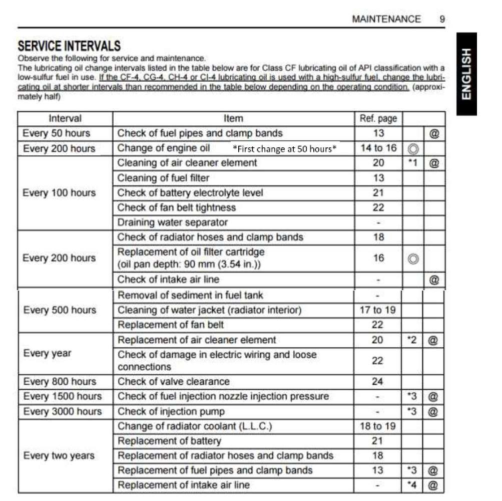
23 When operating in areas with high dust loading, maintenance intervals should be reduced (halved), in particular Air Filter servicing/replacement and change of Engine Oil & Filter, and the replacement of the Fuel Filters. When operating in areas with high dust loading, maintenance intervals should be reduced (halved), in particular Air Filter servicing/replacement and change of Engine Oil & Filter, and the replacement of the Fuel Filters. Page23 Recommended for RSA
24 Page24


25 Hydraulic Schematic / Diagram Page25
26 Notes: Page26
SECTION 1 7 OPERATION OF INSTRUMENTS AND CONTROLS Ignition switch, Transmission and Parking brake
 SECTION 1 7 OPERATION OF INSTRUMENTS AND CONTROLS Ignition switch, Transmission and Parking brake Ignition switch.............................................. 114 Automatic transmission.....................................
Instruction Manual. Vibratory Plate Compactor
 Instruction Manual Vibratory Plate Compactor Model VPC45R Model VPC65R Model VPC85R Model VPC95R Table of Contents 1. INTRODUCTION...1 2. SAFETY...1-2 3. SPECIFICATIONS.....2 4. APPLICATION.. 2 5. CHECK
CAUTION. Start & Stop Procedures. Section 4-2. Engine Oil Level
 Section 4-2 Start & Stop Procedures Before operating this machine, the operator must have: received operator training, a familiarity with this manual, and a complete understanding of all the procedures
Owner s/operator s Manual
 Water Pump MP2533E2 Owner s/operator s Manual Completely read and understand this manual before using this product. Foreword This Owner s/ Operator s Manual is designed to familiarize the operator with
TFP200 FLOOR PLANER OPERATION & MAINTENANCE
 TFP200 FLOOR PLANER OPERATION & MAINTENANCE CS Unitec, Inc. 22 Harbor Avenue, Norwalk, CT 06850 Phone: 203-853-9522 Toll-free: 800-700-5919 Email: info@csunitec.com CS Unitec, Inc. 22 Harbor Avenue, Norwalk,
CAUTION. Start & Stop Procedures. Section 1-2. Engine Oil Level
 Section 1-2 Start & Stop Procedures Before operating this machine, the operator must have: received operator training, a familiarity with this manual, and a complete understanding of all the procedures
Hydraulic Hand Pallet Trucks
 Operating Instructions & Parts Manual 12U124 Please read and save these instructions. Read carefully before attempting to assemble, install, operate, or maintain the product described. Protect yourself
ENGINE DRIVEN 3 FULL TRASH PUMP
 ENGINE DRIVEN 3 FULL TRASH PUMP MODEL NO: PF75 PART NO: 7230165 OPERATION & MAINTENANCE INSTRUCTIONS ORIGINAL INSTRUCTIONS LS0117 ISS 2 INTRODUCTION Thank you for choosing this Clarke Pump. The function
Auger Installation, Operation and Service Manual
 COMP ACT TM Auger Installation, Operation and Service Manual Table of Contents Section 1 Installation of Power Auger Attachment... 1 1 Operating Instructions for Power Auger Attachment... 1 7 Removal
* * * * 8 Maintenance Plan 10.1,10.2, ,4 7.1/7.2/7.3
 Maintenance 8 Maintenance Plan * * * * * GB 10.1,10.2,10.3 6.1 12.2 12.1 11.2 12.1 7,4 7.1/7.2/7.3 1.1/1.2/1.3 3.1/3.2/3.3/3.4/4.1/11.1 5.1 5.2 4.2 5.1 5.2 2.1/2.2/2.3/2.4/2.5/2.6/4.1 Item Designation
610 BUSHEL MANURE SPREADER
 610 BUSHEL MANURE SPREADER RODA MANUFACTURING 1008 LOCUST ST. HULL, IA. 51239 Art s-way Manufacturing 712-439-2366 Co., Inc. Hwy 9 West - PO Box 288 WWW.RODAMFG.COM Armstrong, IA. 50514 U.S.A 2 INTRODUCTION
KMR 1200 B (06/99)
") 1.891-104 5.951-590 (06/99) www.karcher.com Deutsch Betriebsanleitung Seite 3 Ersatzteillieste Seite 57 English Français Español Operating Instructions Page 16 Spare Parts List Page 57 Notice d instructions
1.891-104 5.951-590 (06/99) www.karcher.com Deutsch Betriebsanleitung Seite 3 Ersatzteillieste Seite 57 English Français Español Operating Instructions Page 16 Spare Parts List Page 57 Notice d instructions
DYNAPAC CONCRETE EQUIPMENT RAMIRENT. BG70 Power Floats INSTRUCTIONS & SPARE PARTS CATALOGUE BG70 - IS ENG
 DYNAPAC CONCRETE EQUIPMENT INSTRUCTIONS & SPARE PARTS CATALOGUE BG70 Power Floats BG70 - IS - 10682 - ENG SAFETY INSTRUCTIONS - MACHINES SUBMITTED : Powered with : Electric, Pneumatic, Petrol or Diesel
Finishing Mower Estate 72
 Finishing Mower Estate 72 Owners/Operators Manual & Spare Parts List Issue Date: October 2011 1 Introduction Your FIELDMASTER Estate 72 Finishing Mower has been designed to do a range of work to your satisfaction.
Part 1 OPERATION OF INSTRUMENTS AND CONTROLS
 Part 1 OPERATION OF INSTRUMENTS AND CONTROLS Chapter 1-6 Ignition switch, Transmission and Parking brake Ignition switch with steering lock Automatic transmission Manual transmission Four-wheel drive system
Side Discharge Chute Oil Filler & Dipstick Silencer/Exhaust
 1 SPECIFICATION Electric Start Engine - Size 6HP Engine speed 2850rpm Metal Deck Cutting width 550mm (22 ) Adjustable cutting height 7 Grass collection capacity 60L Gross weight 41Kg Fuel type Unleaded
PowerSafe Two Wheel Tractors
 PowerSafe Two Wheel Tractors Manufactured by BCS S.p.A. Models 710 728 738 740 750 Operating Instructions Before commissioning the machine, read operating instructions and observe warning and safety instructions.
Section 4.3. Machine Operation - Operating Procedures. Before Starting the Engine: General Pre-Start Inspection
 Section 4.3 Machine Operation - Operating Procedures Before Starting the Engine: General Pre-Start Inspection... 4.3.2 Engine Starting Procedure... 4.3.2 Cold Weather Start-Up... 4.3.3 Engine Shutdown
Troubleshooting the Transmission Hydraulic System
 Testing and Adjusting IT28F INTEGRATED TOOLCARRIER POWER TRAIN Testing And Adjusting Introduction Reference: For Specifications with illustrations, refer to SENR5974, IT28F Integrated Toolcarrier Power
MODELS 1324 & 1624 & 1824
 THE MODELS 1324 & 1624 & 1824 HYDRAULIC TRENCHERS CONGRATULATIONS! You are now the proud owner of a BARRETO trencher. Please take a moment of your time to look over the following information. Familiarize
ADESCO.LLC January 21, 2011
 ADESCO.LLC January 21, 2011 Starting Instructions - Extremely important, if not followed, package can and/or will be damaged. Package should be set on a level ground, no exception. 1 Check Fluids daily:
SAFETY/RISK/HAZARD ASSESSMENT
 ZERO TURN MOWER SAFETY/RISK/HAZARD ASSESSMENT PLANT INFORMATION NHG Ref/Part No. Plant ID: Plant Name: Potential Noise Level in Db: Ferris Zero Turn Mower 105db to less than 110db Required hearing protection
WARNING! Ensure that there are no naked flames around the product! Do not smoke while filling fuel and oil!
 Engine Oil and Fuel Engine Operation This product is equipped with a 4 stroke engine. Before operation you have to add proper fuel and engine oil. DO NOT MIXTURE THEM! 1. Place the product on a stable,
POWER UNIT Operations Manual
 PTO-TWIN-ATT & PTO-TWIN-ATT-LP POWER UNIT Operations Manual PTO-TWIN-ATT PTO-TWIN-ATT-LP TNT Rescue Systems, Inc. 2490 West Oak Street Ashippun, WI 53003 920-474-4101 or 800-474-4189 E-Mail: email@tntrescue.com!
SECTION 7 VEHICLE MAINTENANCE AND CARE. Maintenance requirements General maintenance Does your vehicle need repairing?...
 SECTION 7 VEHICLE MAINTENANCE AND CARE Maintenance requirements.................................. 170 General maintenance....................................... 171 Does your vehicle need repairing?............................
PRODUCT OPERATING MANUAL
 PRODUCT OPERATING MANUAL PANBLAST TM BP110 3 BLAST POT Manual Number: ZVP PC 0155 00 SECTION 1. GENERAL INFORMATION 2. INITIAL SETUP INSTRUCTIONS 3. OPERATING INSTRUCTIONS 4. MAINTENANCE 5. TROUBLE SHOOTING
MOTORINI GP 50. User s Manual.
 MOTORINI GP 50 User s Manual www.motorini.co.uk Dear user: Thank you for choosing to buy a Motorini GP 50 This manual provides the correct operation and maintenance methods for safe riding and maintaining
Skid Steer Loader. Owner s and Operator s Manual. PUBLICATION NO July 2003
 175 Skid Steer Loader Owner s and Operator s Manual PUBLICATION NO. 48609 July 2003 THOMAS EQUIPMENT LIABILITY WARRANTY THE WARRANTY IS THE ONLY OBLIGATION OF THOMAS OR A THOMAS DEALER TO THE PURCHASER
11 OPERATION AND VERIFICATION
 11 OPERATION AND VERIFICATION Section Page 11.1 PREPARATION FOR A FIRST TIME START... 11-3 11.2 STARTING THE ENGINE... 11-9 11.3 RUNNING THE ENGINE... 11-12 11.4 STOPPING THE ENGINE... 11-14 (Rev. 3/04)
Section 4.3. Machine Operation - Operating Procedures. Before Starting the Engine: General Pre-Start Inspection
 Section 4.3 Machine Operation - Operating Procedures Before Starting the Engine: General Pre-Start Inspection... 4.3.2 Engine Starting Procedure... 4.3.2 Cold Weather Start-Up... 4.3.3 Engine Shutdown
ATV-320 R OWNER S MANUAL
 ATV-320 R OWNER S MANUAL FOREWORD May we, the manufacturer, take this opportunity to thank you for choosing our ATV to serve you. This Owner s Manual is prepared for you to properly operate in safety.
Backhoe for Dingo Compact Utility Loaders
 Form No. 50-5 Backhoe for Dingo Compact Utility Loaders Model No. 60 000000 & Up Operator s Manual Original Instructions (EN/GB) Contents Page Introduction................................. Safety......................................
PRODUCT OPERATING MANUAL
 PRODUCT OPERATING MANUAL PANBLAST TM BP50 3 BLAST POT Manual Number: ZVP PC 0156 00 SECTION 1. GENERAL INFORMATION 2. INITIAL SETUP INSTRUCTIONS 3. OPERATING INSTRUCTIONS 4. MAINTENANCE 5. TROUBLE SHOOTING
RedGum GP160 Splitter. Owner s Manual
 RedGum GP160 Splitter Owner s Manual Product Description & Intended Purpose: This Log Splitter / Wood Splitter is an outdoor product that splits wood logs for use as fuel in a fireplace or a woodstove.
DANGER: RISK OF FLYING DEBRIS.
 Page 1 of 6 Section 1: Equipment Identification and Supplier details Name Mikasa Reversible Plate Compactor MVH-308 Diesel Recommended Use The machine also works well for compacting, flattening and levelling
SECTION 5 MAINTENANCE. For scheduled maintenance information, please refer to the separate Owner s Manual Supplement/ Maintenance Schedule.
 SECTION 5 Maintenance requirements 180 General maintenance 181 Does your vehicle need repairing? 184 For scheduled maintenance information, please refer to the separate Owner s Manual Supplement/ Maintenance
SAFETY AND OPERATION REQUIREMENTS CHART
 OPERATION, MAINTENANCE and SAFETY MANUAL MB16 and MTB16 Scoot-Crete Power Buggies IMPORTANT MACHINE SERVICE NOTES This manual covers the safety, operation and adjustment procedures for the Miller Scoot-Crete
PRODUCT OPERATING MANUAL
 PRODUCT OPERATING MANUAL PANBLAST TM BP600 3 BLAST POT Manual Number: ZVP PC 0154 00 SECTION 1. GENERAL INFORMATION 2. INITIAL SETUP INSTRUCTIONS 3. OPERATING INSTRUCTIONS 4. MAINTENANCE 5. TROUBLE SHOOTING
Part 1 OPERATION OF INSTRUMENTS AND CONTROLS
 Part 1 OPERATION OF INSTRUMENTS AND CONTROLS Chapter 1-5 Gauges, Meters and Service reminder indicators Fuel gauge Engine coolant temperature gauge Oil pressure gauge Voltmeter Tachometer Odometer and
TIN KNOCKER TK H1652 Hydraulic Shear
 TIN KNOCKER TK H1652 Hydraulic Shear INSTRUCTIONS & PARTS DIAGRAM TAAG INDUSTRIES CORP. 1550 SIMPSON WAY, ESCONDIDO, CA 92029 Tel: (800) 640-0746 Fax: (760) 727-9948 Website: www.tinknocker.com Email:
M. E. Y. EQUIPMENT MOWER MANUAL
 M. E. Y. EQUIPMENT MOWER MANUAL 200 COLLIER ROAD, BAYSWATER. WESTERN AUSTRALIA 6053 TELEPHONE (08) 9370 1110, FACSIMILE (08) 9370 2566 Web Site: www.mey.com.au Email: info@mey.com.au INTRODUCTION The technical
! WARNING! Read This Manual Before Operating Equipment
 ATT-6.5, ATT-6.5-RC, ATT-6.5-LP, ATT-6.5-LP-RC POWER UNIT Operations Manual ATT-6.5 ATT-6.5-RC ATT-6.5-LP ATT-6.5-LP-RC TNT Rescue Systems, Inc. 2490 West Oak Street Ashippun, WI 53003 920-474-4101 or
 3 Protecting Your Xedos Vehicle FUEL REQUIREMENTS EMISSION CONTROL SYSTEM BEFORE DRIVING RUNNING-IN ECONOMICAL OPERATION SPECIAL DRIVING CONDITIONS LABEL INFORMATION 3-2 3-2 3-3 3-4 3-4 3-5 3-8 3-1 3-2
ATV-320 S/U ATV-320SD S/U OWNER S MANUAL V
 ATV-320 S/U ATV-320SD S/U OWNER S MANUAL V1.0 2014.03.01 0 FOREWORD May we, the manufacturer, take this opportunity to thank you for choosing our ATV to serve you. This Owner s Manual is prepared for you
FB 300 FB 450 FB 700 USER MANUAL
 FB 300 FB 450 FB 700 USER MANUAL 2 USE SWEPAC FB 300 / FB 450 / FB 700 are used to pack ballast under foundations, in connection with road building, in trenches, etc. On account of the forward/reverse
ATV-50/90/100 I/II/V OWNER S MANUAL
 1 ATV-50/90/100 I/II/V OWNER S MANUAL FOREWORD May we, the manufacturer, take this opportunity to thank you for choosing our ATV to serve you. This Owner s Manual is prepared for you the details as to
Wheel Horse. 44 Snowthrower. for 5xi Lawn and Garden Tractors. Model No & Up. Operator s Manual
 FORM NO. 8 Rev A Wheel Horse Snowthrower for 5xi Lawn and Garden Tractors Model No. 7966 890050 & Up Operator s Manual IMPORTANT: Read this manual, and your tractor manual, carefully. They contain information
MODEL HD99 HYDRAULIC ONE MAN TOWABLE EARTHDRILL
 DO NOT THROW AWAY IMPORTANT MANUAL MODEL HD99 HYDRAULIC ONE MAN TOWABLE EARTHDRILL Operators Manual GROUND HOG, INC. P.O.BOX 290 San Bernardino, CA. 92402 Phone (909) 478-5700 Fax (909) 478-5710 E-mail:
Ride on roller Note: It is recommended that you read the Supporting Information page before you read this factsheet.
 Ride on roller Note: It is recommended that you read the Supporting Information page before you read this factsheet. Preparation and completing work (Preparation) Ride on rollers fall into the category
INSTALLATION / OPERATING INSTRUCTIONS Reese Elite Series FIFTH WHEEL SLIDER HITCH
 INSTALLATION / OPERATING INSTRUCTIONS Reese Elite Series FIFTH WHEEL SLIDER HITCH DEALER/INSTALLER: (1) Provide this Manual to end user. (2) Physically demonstrate hitching and unhitching procedures in
May we, the manufacturer, take this opportunity to thank you for choosing our ATV to serve you.
 FOREWORD May we, the manufacturer, take this opportunity to thank you for choosing our ATV to serve you. This Owner s Manual is prepared for you the details as to operate and maintenance necessarily to
Beton Trowel nv INSTRUCTION MANUEL SLAB SAW BTCS500 - GEBABEBB BBRUBEBB BNP FORTIS: ING: BE BE
 INSTRUCTION MANUEL SLAB SAW BTCS500 BBRUBB 1/20 Use this guide along with the parts lists attached to locate and identify components of your trowel. When ordering replacement parts, be sure to provide
MODEL 912RM/912HM HYDRAULIC TRENCHER OPERATOR S MANUAL
 THE MODEL 912RM/912HM HYDRAULIC TRENCHER OPERATOR S MANUAL TRENCHER INTENDED USE This machine is designed for digging trenches in normal ground of reasonably soft dirt and stones up to 6 (15cm) in diameter.
I: INSPECT AND CLEAN, ADJUST, LUBRICATE OR REPLACE IF NECESSARY C: CLEAN A: ADJUST R: REPLACE L: LUBRICATE I: INSPECTION D: DIAGNOSE
 2. Periodic Maintenance > Periodic Maintenance Chart XCITING 400i Maintenance Schedule Perform the pre-ride inspection (Owner's Manual) at each scheduled maintenance period. This interval should be judged
HYDRAULIC PALLET TRUCK MODEL NO: PT540M/BM/CM & PT685BM/CM PART NO: , , , ,
 HYDRAULIC PALLET TRUCK MODEL NO: PT540M/BM/CM & PT685BM/CM PART NO: 7631700, 7631705, 7631710, 7631715, 7631720 OPERATION & MAINTENANCE INSTRUCTIONS LS0316 INTRODUCTION Thank you for purchasing this CLARKE
Trench Filler for Compact Utility Loaders
 Form No. 3353-608 Rev A Trench Filler for Compact Utility Loaders Model No. 22472 260000001 and Up Operator s Manual Register your product at www.toro.com Original Instructions (EN) Contents Page Introduction................................
KEYSTONE SERIES 320 BUTTERFLY VALVES INSTALLATION AND MAINTENANCE INSTRUCTIONS
 Before installation these instructions must be fully read and understood HAZARD POTENTIALS disregarding of instructions improper use of product insufficiently qualified personnel Valve application to be
MORRISON MS-40C MATERIAL SPREADER
 INSTRUCTION MANUAL & PARTS BOOK MORRISON MS-40C MATERIAL SPREADER POWERFUL - EFFICIENT - DEPENDABLE 25 INDUSTRIAL DRIVE, KEYPORT, NEW JERSEY, USA, 07735, 732-566-5400 FAX 732-5444 Doc. # OI M09203 PB M09203
FB 160 FB 175 FB 235 FB 255 FB 265 USER MANUAL IN ORIGINAL
 FB 160 FB 175 FB 235 FB 255 FB 265 USER MANUAL IN ORIGINAL 2 USE SWEPAC FB160 / FB 175 / FB 235 / FB 255 / FB 265 are used to pack ballast under foundations, in connection with road building, in trenches,
AIR BRAKES THIS SECTION IS FOR DRIVERS WHO DRIVE VEHICLES WITH AIR BRAKES
 Section 5 AIR BRAKES THIS SECTION IS FOR DRIVERS WHO DRIVE VEHICLES WITH AIR BRAKES AIR BRAKES/Section 5 SECTION 5: AIR BRAKES THIS SECTION COVERS Air Brake System Parts Dual Air Brake Systems Inspecting
Operating and Installation Instructions Diaphragm Vacuum Pumps and Compressors
 Operating and Installation Instructions Diaphragm Vacuum Pumps and Compressors Type range: UN813.3ANI UN813.4ANI UN813.3ANDCB UN813.4ANDCB UN813.5ANI Fig. 1: UN813.3ANI Fig. 2: UN813.4ANI You have selected
INSTALLATION & USER S GUIDE
 REKLUSE MOTOR SPORTS The Rekluse Core EXP Kit for Kawasaki KX80/85/100 OVERVIEW INSTALLATION & USER S GUIDE Doc ID: 191-7742A Doc Rev: 073015 This kit replaces the OEM core clutch components including
Timer. TipTop Timers. Installation and Operation Manual
 TipTop s E TM Installation and Operation Manual Sold by: TipTop s LLC 2225 North Dollar Road Spokane Valley, WA 99212 web: Model T Electronic - E E Conversion Kit Contents The Electronic conversion kit
North Dakota State University Grounds Maintenance Equipment
 North Dakota State University Grounds Maintenance Equipment I. Introduction Grounds maintenance equipment is an important part of the work activities on NDSU campus. They can make grounds maintenance jobs
5.5KVA GENERATOR MODEL NO: PG6500DVES OPERATION & MAINTENANCE INSTRUCTIONS PART NO: LS0616
 5.5KVA GENERATOR MODEL NO: PG6500DVES PART NO: 8857810 OPERATION & MAINTENANCE INSTRUCTIONS LS0616 INTRODUCTION Thank you for purchasing this CLARKE 5.5KVA Generator. Before attempting to use this product,
MTD OHV Series FORM NO B. jqa=mêççìåíë=^âíáéåöéëéääëåü~ñí= =p~~êäêωåâéå= =déêã~åó
 MTD OHV Series J15 FORM NO. 769-08890B jqa=mêççìåíë=^âíáéåöéëéääëåü~ñí= =p~~êäêωåâéå= =déêã~åó 4 11 19 27 35 43 51 58 65 72 79 87 96 104 112 119 126 134 141 148 155 162 171 179 188 197 206 213 221
TCI Trans-Scat
 Page 1 of 5 Return to Instruction Sheet index TCI 350000 Trans-Scat Installation Instructions For TURBO HYDRAMATIC 350 This kit will allow you to reprogram your transmission to meet your driving needs
MODEL 1324ST ST HYDRAULIC TRENCHER OPERATOR S MANUAL
 THE MODEL 1324ST - 1624ST HYDRAULIC TRENCHER OPERATOR S MANUAL TRENCHER INTENDED USE This machine is designed for digging trenches in normal ground of reasonably soft dirt and stones up to 6 (15cm) in
Instruction Manual. Vibratory Reversible Plate Compactor
 Instruction Manual Vibratory Reversible Plate Compactor Model VPR300 Model VPR400 Foreword This manual has been written to help you operate your Vibratory Reversible Compactor safely. It is intended primarily
Rotavators. Operating Instructions. Before commissioning the machine, read operating instructions and observe warning and safety instructions.
 Rotavators with PowerSafe Clutch MODELS C8 C10 C13 Operating Instructions Before commissioning the machine, read operating instructions and observe warning and safety instructions. PLEASE ALSO READ ORIGINAL
3KVA DUAL VOLTAGE GENERATOR MODEL NO: PG3800DV
 3KVA DUAL VOLTAGE GENERATOR MODEL NO: PG3800DV PART NO: 8857815 OPERATION & MAINTENANCE INSTRUCTIONS LS1016 INTRODUCTION Thank you for purchasing this CLARKE 3KVA Dual Voltage Generator. Before attempting
Backhoe for Compact Utility Loaders
 Form No. 54-4 Rev A Backhoe for Compact Utility Loaders Model No. 6 6000000 and Up Operator s Manual Register your product at www.toro.com. Original Instructions (EN) Contents Page Introduction.................................
INSTALLATION & USER S GUIDE
 REKLUSE MOTOR SPORTS The Rekluse Core EXP Kit with Adjustable Slave Cylinder INSTALLATION & USER S GUIDE Doc ID: 191-7704A Doc Rev: 102915 OVERVIEW This kit replaces the OEM core clutch components including
BT-1.5, BT-1.5-LP (NITRO) POWER UNIT Operations Manual
 POWER UNIT Operations Manual") BT-1.5, BT-1.5-LP (NITRO) POWER UNIT Operations Manual BT-1.5 BT-1.5-LP TNT Rescue Systems, Inc. 2490 West Oak Street Ashippun, WI 53003 920-474-4101 or 800-474-4189 E-Mail: email@tntrescue.com! WARNING!
BT-1.5, BT-1.5-LP (NITRO) POWER UNIT Operations Manual BT-1.5 BT-1.5-LP TNT Rescue Systems, Inc. 2490 West Oak Street Ashippun, WI 53003 920-474-4101 or 800-474-4189 E-Mail: email@tntrescue.com! WARNING!
Eaton 9-Speed Synchronized Transmissions Single H Shift Control Configuration TRDR0072
 Driver Instructions Eaton 9-Speed Synchronized Transmissions Single H Shift Control Configuration TRDR0072 February 2008 FS(O) 6109 FS(O) 6209 FS(O) 6309 FS(O) 8209 FS(O) 8309 FS(O) 10209 FS(O) 10309 Warnings
Preventive maintenance 4
 00 Series Preventive maintenance Preventive maintenance periods Use the procedures in this chapter to maintain your engine in accordance with the preventive maintenance schedule. Check the periods given
INSPECTION/ADJUSTMENT
 3 3 INSPECTION/ADJUSTMENT SERVICE INFORMATION----------------------------------------------------------------------- 3-1 MAINTENANCE SCHEDULE-------------------------------------------------------------------
F B F B USER MANUAL. spac100. Dok: A-GB 0820
 F B 2 2 5 F B 2 5 0 USER MANUAL spac100 USE SWEPAC FB 225 / FB 250 are used to pack ballast under foundations, in connection with road building, in trenches, etc. On account of the forward/reverse function,
SECTION 3 1 STARTING AND DRIVING
 SECTION 3 1 STARTING AND DRIVING Starting and driving Three way catalytic converter 126 Engine exhaust caution 127 Before starting the engine 128 Ignition switch with steering lock 128 Parking brake 129
Australia s best value ebikes
 IMPORTANT NOTICE Read manual, Instructions and Terms carefully before use. It is the buyer s responsibility to make sure the drift trike is safe to ride. If necessary ask for help at any good local bicycle
1500 Series Roll Off Hoist. Owner s Manual (5-06)
") 1500 Series Roll Off Hoist Owner s Manual (5-06) Section 1: General Information Introduction Safety Information Warranty Information Table of Contents Section 2: Operation Operating the P.T.O. Operating
1500 Series Roll Off Hoist Owner s Manual (5-06) Section 1: General Information Introduction Safety Information Warranty Information Table of Contents Section 2: Operation Operating the P.T.O. Operating
LEARNER GUIDE. Roller - LR. PO Box 2026 Mountain Gate VIC 3156 p: ABN: RTO: 21396
 LEARNER GUIDE Roller - LR PO Box 2026 Mountain Gate VIC 3156 p: 03 9763 5449 ABN: 37 106 951 900 RTO: 21396 Assessor Guidelines Specific (Performance Assessment) ASSESSMENT INSTRUMENT SPECIATIONS The performance
Part No amatic 350
 Watch our installation video on YouTube Installation Instructions Shift Improver Kit Part No. 30262 1968-1981 TurboHy urbohydr drama amatic 350 B&M Racing and Performance Products 2002 Congratulations!
DU-ALL SAFETY FORKLIFT TRUCK OPERATORS TRAINING COURSE WRITTEN TEST PART 1 OPERATOR S NAME DATE
 DU-ALL SAFETY FORKLIFT TRUCK OPERATORS TRAINING COURSE WRITTEN TEST PART 1 OPERATOR S NAME DATE MULTIPLE CHOICE (select the answer which is most correct and circle the letter.) 1. A lift truck training
KEYSTONE. Butterfly valves Figure 9 Installation & Maintenance Instructions. Please read these instructions carefully
 KEYSTONE Please read these instructions carefully This symbol indicates important messages and safety instructions. Hazard potentials: disregarding of instructions improper use of product insufficiently
AUTOMATIC LEVELING SYSTEM OPERATION & MAINTENANCE
 WARNING For maximum stability during use of the PowerPlus Leveling Systems, all levelers and wheels must be in contact with the ground. NEVER use levelers to change tires or to perform under chassis work
Fuel and refuelling SAFETY PRECAUTIONS FUEL QUALITY
 SAFETY PRE Automotive fuels can cause serious injury and even death, if misused. Petroleum gasses are highly flammable, have a low flash point, and are explosive, especially in confined spaces. Avoid exposing
16A. STARTING - CHARGING Starter: Removal - Refitting REFITTING 16A-11 K4M II - REMOVAL OPERATION III - FINAL OPERATION
 STARTING - CHARGING Starter: Removal - Refitting 16A K4M II - REMOVAL OPERATION III - FINAL OPERATION JR5 a Clip: -the gearbox control cable sleeve stops on the gearbox, - the control cables onto the gearbox.
Commander 15i Container and Pallet Loader. Property of American Airlines
 Commander 15i Container and Pallet Loader Section 2. Operation BEFORE ATTEMPTING TO OPERATE OR MAINTAIN THE VEHICLE, COMPLETELY READ AND UNDERSTAND THE OPERATION AND MAINTENANCE MANUAL, INCLUDING ALL DANGER,,
Property of American Airlines
 MH Utility Vehicle Section 2 SECTION 2: OPERATION A. CONTROLS, INSTRUMENTS AND SWITCHES The tractor controls and instruments include a headlight switch, ignition switch, hour meter, ammeter (if equipped),
Return to Instruction Sheet index TCI Installation Instructions for Turbo Hydramatic 350C & 250C
 Page 1 of 6 Return to Instruction Sheet index TCI 326300 Installation Instructions for Turbo Hydramatic 350C & 250C NOTE: This kit was not intended for installation in transmissions that are in poor general
SECTION 1-6 OPERATION OF INSTRUMENTS AND CONTROLS 05 HIGHLANDER_U (L/O 0409) Gauges, Meters and Service reminder indicators
 Gauges, Meters and Service reminder indicators") SECTION 1-6 OPERATION OF INSTRUMENTS AND CONTROLS Gauges, Meters and Service reminder indicators Fuel gauge................................................ 132 Engine coolant temperature gauge...........................
SECTION 1-6 OPERATION OF INSTRUMENTS AND CONTROLS Gauges, Meters and Service reminder indicators Fuel gauge................................................ 132 Engine coolant temperature gauge...........................
WARNING: the engine does not come with oil in it. Please fill the oil before starting. The 200cc hardknock requires 9/10 of a quart of oil.
 WARNING: the engine does not come with oil in it. Please fill the oil before starting. The 200cc hardknock requires 9/10 of a quart of oil. Things needed for assembly. -2 tubes of blue loc-tite. I don
T105. Skid Steer Loader. Owner s and Operator s Manual
 T105 Skid Steer Loader Owner s and Operator s Manual PUBLICATION NO. 47639 September, 2001 THOMAS EQUIPMENT LIABILITY WARRANTY THE WARRANTY IS THE ONLY OBLIGATION OF THOMAS OR A THOMAS DEALER TO THE PURCHASER
FTFR Maintenance and Parts Manual SQ-1 FLOOR TRUSS FINISH ROLLER. Operators Manual
 FTFR Maintenance and Parts Manual SQ-1 FLOOR TRUSS FINISH ROLLER Operators Manual FOREWORD This manual explains the proper maintenance of Square 1 Design Floor Truss Finish Roller as well as the daily
SUNY GENESEO ENVIRONMENTAL HEALTH & SAFETY
 Prepared by: Darlene Necaster Page 1 I. OVERVIEW Material handling is a significant safety concern. During the movement of products and materials, there are a number of opportunities for injuries and property
SECTION 3.00 WARNING WARNING ENGINE STARTUP AND SHUTDOWN PRESTART INSPECTION
 SECTION 3.00 ENGINE STARTUP AND SHUTDOWN PRESTART INSPECTION Be sure that the clutch, circuit breaker, or other main power transmission device is disconnected. Generators develop voltage as soon as the
This chapter describes how to perform periodic inspection and maintenance to ensure the long operating life of the chamber.
 Basic guide Chapter 5 Inspection and maintenance Air to Air Thermal Shock Chamber Chapter 5 Inspection and maintenance This chapter describes how to perform periodic inspection and maintenance to ensure
THE ERGO-MATIC DRUM TRANSPORT POWER DRIVE SERIES MODEL PWPL 750 OWNERS MANUAL
 THE ERGO-MATIC DRUM TRANSPORT POWER DRIVE SERIES MODEL PWPL 750 OWNERS MANUAL WARNING: Do not install, operate or service this product unless you have read and understand the safety practices, warnings,
T245 HDK. Skid Steer Loader. Owner s and Operator s Manual
 T245 HDK Skid Steer Loader Owner s and Operator s Manual PUBLICATION NO. 47640 August, 2001 THOMAS EQUIPMENT LIABILITY WARRANTY THE WARRANTY IS THE ONLY OBLIGATION OF THOMAS OR A THOMAS DEALER TO THE PURCHASER