Read This First! DANGER DANGER indicates a hazardous situation which, if not avoided, will result in death or serious injury.
|
|
|
- Jesse Blankenship
- 5 years ago
- Views:
Transcription
1
2 Read This First! Congratulations on purchasing a new Kawasaki JET SKI watercraft. Your safety and the safety of other people is very important. The operator of the JET SKI watercraft is responsible for operating it safely. This Owner s Manual explains how to operate the JET SKI watercraft properly to protect you and other people from injury.the first part of this manual, and the instructions under " DANGER" and " WARNING" in the main text are particularly important for ensuring safety. Please read them carefully and be sure to follow the warnings and instructions. Safety alert symbols These safety symbols alert the user to a possible human risk. Be sure to follow all safety instructions that follow these symbols to avoid accidents that could result in personal injury or death. Precautionary statements These warnings indicate situations that could result in death or serious injury of the rider or other persons involved, or damage to the watercraft, and instructions on how to avoid them. The following symbols areusedtoindicatetheseriousnessofthedanger. DANGER DANGER indicates a hazardous situation which, if not avoided, will result in death or serious injury. WARNING WARNING indicates a hazardous situation which, if not avoided, could result in death or serious injury. NOTICE NOTICE is used to address practices not related to personal injury. NOTE NOTE indicates information that may help or guide you in the operation or service of the vehicle.
3 About This Manual Please keep this Owner s Manual for future reference. If you resell or transfer your JET SKI watercraft, be sure to provide this manual with the product. Keep this Owner s Manual aboard your JET SKI watercraft in a waterproof bag at all times so that you can refer to it whenever necessary. The information in this Owner s Manual may not completely match the actual product due to changes in the specifications. Design Category This craft is an inboard boat less than 4.8 m (16 ft) in length and, as such, is subject to all federal rules and regulations especially pertaining to boating safety and operation as enforced by the U.S. Coast Guard. States and local jurisdictions may have additional requirements for operation of powerboats in waters under their control. Additionally, other countries may have their own standards and regulations. Please check your local boating laws and regulationsbefore riding the watercraft. ********************************************************** WARNING Engine exhaust, some of its constituents, and certain product components contain or emit chemicals known to the State of California to cause cancer and birth defects or other reproductive harm. is a trademark of Kawasaki Heavy Industries, Ltd. registered in U.S.A., Japan, Austria, Benelux, Sweden, Denmark, Switzerland, France, Canada, Finland, Norway, Greece, Italy, U.K., Portugal, Thailand, and Taiwan. KAWASAKI JET SKI is a trademark of Kawasaki Heavy Industries, Ltd. registered in Australia. All rights reserved. No part of this publication may be reproduced without our prior written permission Kawasaki Heavy Industries, Ltd. Apr. 5, (1)
4 Quick Reference Guide SAFETY INFORMATION j This Quick Reference Guide will assist you in finding the information you re looking for. PREVENT MAJOR DAMAGE GENERAL INFORMATION j j PRE-RIDE CHECK j OPERATING INSTRUCTIONS j TRANSPORTING AND STORAGE j MAINTENANCE AND ADJUSTMENTS j IN AN EMERGENCY j APPENDIX j A Table of Contents is included after the Foreword. MAINTENANCE RECORD j
5 TABLE OF CONTENTS SAFETY INFORMATION... 7 Read Owner s Manual Thoroughly before Operation... 7 Wear PFD, Protective Clothing and Gear... 7 Personal Flotation Device (PFD)... 7 Wet Suit Bottoms or Other Protective Clothing... 8 Other Protective Gear... 8 Know Boating Laws... 9 Occupants and Load Limit... 9 Attach Engine Shut-Off Cord (Lanyard) Ride within Your Limits Do not Jump Wakes or Waves Never Ride after Consuming Drugs or Alcohol Do not Apply Throttle when Anyone is Behind Keep Away from Intake Grate Avoid Collision Ventilate Engine Compartment Keep Your Watercraft in Safe Condition Pre-Ride Check Regular Maintenance / Modification Never Operate after Dark Follow Rules Label Location PREVENT MAJOR DAMAGE Tilting the Watercraft Righting Capsized Watercraft Shallow Water Wave Jumping After daily riding Jet Pump and Seals Periodic Maintenance GENERAL INFORMATION Parts Location Multifunction Meter Speedometer Tachometer Multifunction Displays Fuel Level Gauge/ FUEL Character/Warning Indicator Light Engine Oil Pressure Indicator/ OILP Character/Warning Indicator Light Engine Cooling Water Temperature Indicator/ HEAt character/warning Indicator Light Low Battery Voltage Indicator/ bat Character/Warning Indicator Light Engine Oil Temperature Indicator/ OILt Character/Warning Indicator Light Engine Oil Overheat Indicator/ OILH Character/Warning Indicator Light Engine Warning Indicator/ FI Character/Warning Indicator Light Immobilizer Amplifier Indicator/ Innb Character/Warning Indicator Light Immobilizer Key Matching Indicator/ I9nI Character/Warning Indicator Light Communication Trouble Indicator/ Err Character/Warning Indicator Light Fuel Fuel Requirements... 48
6 Filling the Tank Ignition Switch SLO/FPO Modes Smart Learning Operation mode (SLO) How to use the Immobilizer-function keys.. 54 Lost Keys Declaration of conformity Controls Tilt Lever Kawasaki Smart Steering TM (KSS TM ) Important Information Stop Button Engine Shut-off Lanyard Key Start Button Throttle Lever Shift Lever Seat Latches Storage Compartment Center and Rear Storage Cases Tool Kit Bilge Systems Drain Screws Handrail Reboarding Step Loading/Accessories/Modifications Maximum load Towing (a wakeboarder, water skier, tuber, etc.) Towing a wakeboarder/water skier/tuber Roles of the watercraft operator Roles of the observer Towing a personal watercraft PRE-RIDE CHECK OPERATING INSTRUCTIONS Basic Knowledge for Operation Operation by unskilled riders Operator Swimming Ability Maximum Number of Persons Safe Riding Rules Personal Flotation Device and Safety Gear 76 Watercraft Helmet... Something You Should Know Fire Extinguisher Weather condition Basic Operating and Riding PostureontheSeats Operation with Passengers Boarding from Water Break-In Stopping the Engine Starting the Engine Launching Launching/Start Stopping the JET SKI Watercraft Turning the JET SKI Watercraft Operating the JET SKI Watercraft in Reverse Docking the JET SKI Watercraft Fall Recovery Righting the Capsized Watercraft After Submerging End of the Day Checklist Drain the Exhaust System Clean the Engine Compartment Clearing Clogged Impeller TRANSPORTING AND STORAGE Transporting STORAGE
7 Preparation for Storage Removal from Storage MAINTENANCE AND ADJUSTMENTS EMISSION CONTROL INFORMATION Periodic Maintenance Chart Control Cables Fuel System Throttle Adjustments Fuel Vent Check Valve Fuel Pump Screen Fuel Hose Engine Oil Oil Requirements Oil Level Inspection Oil and/or Oil Filter Changes Valve Clearance Spark Plugs Battery Lubrication Cooling System Flushing Bilge System Flushing Jet Pump Bearings/Seals Fuses IN AN EMERGENCY Troubleshooting Guide In the Case of Emergency Towing the JET SKI watercraft Jump Starting APPENDIX YOUR WARRANTY/OWNER SATISFACTION REPORTING SAFETY DEFECTS ENVIRONMENTAL PROTECTION Environmental Hang Tag SPECIFICATIONS Serial Numbers Registration Numbers MAINTENANCE RECORD
8 Important. Read this carefully. SAFETY INFORMATION 7 SAFETY INFORMATION WARNING j Read Owner s Manual Thoroughly before Operation Carefully read the instructions in every WARN- ING message in the owner s manual and on every warning label on your JET SKI watercraft before operating. Be sure to observe these instructions. The owner s manual and the warning labels provide important safety information. Wear PFD, Protective Clothing and Gear Personal Flotation Device (PFD) All riders must wear a Coast Guard approved personal flotation device (PFD) that is suitable for personal watercraft (PWC) use. Kawasaki recommends a vest-type PFD. Hard impact with the water can result in loss of consciousness and drowning. Make sure that your PFD fits correctly so that it does not come off in the water. Never use an adult size PFD for children.
9 8 SAFETY INFORMATION Important. Read this carefully. Wet Suit Bottoms or Other Protective Clothing All riders must wear wet suit bottoms (neoprene shorts) or clothing that provides equivalent protection against possible injury to body cavities. Normal swimwear will not provide adequate protection. Injury from Forced Injection of Water into Body Cavities (Rectum or Vagina) As a result of falling into water or being near the jet thrust nozzle, water can be forced into body cavities such as the rectum or vagina. This could cause damage to abdominal organs, possibly resulting in death or severe injury. Wet suit bottoms are made of a thick material (neoprene) that significantly retards the velocity of water passing through it. In addition to wet suit bottoms, some other aquatic wear may protect against body cavity injuries. If wet suit bottoms are not available, you should select clothing that will maximize your protection. Materials that are thicker, have a tighter weave, are water repellent, or that are tighter fitting tend to provide more protection. Clothing that may be displaced by the force of water will not provide adequate protection. Other Protective Gear Wear protective footwear, gloves and goggles (glasses). Wear suitable eye protection such as goggles while operating the watercraft. Water spray can damage your eyes, or momentarily interfere with your vision, which may lead to an accident. Floatable goggles are recommended. Wear foot protection such as deck shoes or tennis shoes. Submerged shells, rocks or other objects can injure your feet. A. Jet Thrust Nozzle
10 Important. Read this carefully. SAFETY INFORMATION 9 Know Boating Laws Occupants and Load Limit j Kawasaki recommends a minimum operator age of 16 years old. Know the operator age and training requirements for your state or region. A boating safety course is recommended and may be required in your state or region. Boat Smart from the Start Take a boating safety course and get a free vessel safety check annually for your boat. For more information contact: United States Coast Guard Auxiliary, / United States Power Squadrons, 888-for-usps, Occupants limit Load limit 3 persons (1 operator and 2 passengers) 2 persons (1 operator and 1 observer) when towing a water skier, wakeboarder, or tuber 225 kg (496 lb) including riders and cargo Exceeding the maximum number of occupants or the load limit can adversely affect the handling and stability of this watercraft, which can lead to an accident. Do not exceed the maximum capacity. All passengers must ride on the designated seats.
11 10 SAFETY INFORMATION Important. Read this carefully. Attach Engine Shut-Off Cord (Lanyard) Attach the engine shut-off cord (lanyard) to your wrist whenever operating this watercraft so that the engine stops if the operator falls off. Keep the lanyard free from the handlebars or other objects. After riding, remove the lanyard from the watercraft to avoid unauthorized use by children or others. Ride within Your Limits Ride within your limits and avoid aggressive maneuvers to reduce the risk of loss of control, ejection, and collision. - The JET SKI watercraft is a high-performance boat - not a toy. Do not operate the watercraft with any passengers on board until you have enough operating experience alone. Operating the watercraft with passengers requires good operating skills. Be accustomed to the handling characteristics of the watercraft and do practice well before operating with a passenger. A. Engine Shut-Off Cord B. Engine Stop Button C. Lanyard Key
12 Important. Read this carefully. SAFETY INFORMATION 11 Do not Jump Wakes or Waves Sharp turns or jumping wakes or waves can increase the risk of back/spinal injury (paralysis), facial injuries, and broken legs, ankles and other bones. Never Ride after Consuming Drugs or Alcohol Never ride under the influence of or after consuming drugs or alcohol. Ensure your passengers are also free from drugs or alcohol. j

13 12 SAFETY INFORMATION Important. Read this carefully. Do not Apply Throttle when Anyone is Behind Do not apply throttle when anyone is behind the JET SKI watercraft. - Turn the engine off or keep it at idle. Water and/or debris ejected from the jet thrust nozzle can cause severe injury. Keep Away from Intake Grate Keep away from the intake grate while the engine is on. - Items such as long hair, loose clothing, or PFD (personal flotation device) straps can become entangled in moving parts, resulting in severe injury or drowning. A. Intake Grate B. Jet Thrust Nozzle


14 Important. Read this carefully. SAFETY INFORMATION 13 Avoid Collision Collisions couse more injuries and deaths than any other type of personal watercraft accident. To avoid collisions, know the characteristics of your watercraft and observe all warnings. Scan constantly for people, objects, and other watercraft. - Be alert for conditions that limit your visibility or block your vision of others. - Do not go near people or others to spray or splash them with water. - Avoid sharp turns or other maneuvers that make it hard for others to avoid you or understand where you are going. Avoid areas with submerged objects or shallow waters. Take early action to avoid collisions. Remember personal watercraft and other boats do not have brakes. Do not release the throttle when trying to steer away from objects. You need throttle to steer. - To avoid collisions you must have thrust to turn. Turn with Thrust j Ride in safe water areas. Operate defensively at safe speeds and keep a safe distance away from people, objects and other watercraft. - Do not follow directly behind other watercraft or boats.

15 14 SAFETY INFORMATION Important. Read this carefully. No Thrust = No Turn Ventilate Engine Compartment Open the engine compartment to ventilate it before starting the engine. A concentration of gasoline fumes can cause a fire or explosion. Do not start the engine if there is a fuel leak or gasoline fumes. Before each ride, and after refueling or transportation, ventilate the engine compartment for several minutes with the storage compartment lid open and the seats removed. Do not stop the engine to avoid a collision. - If you push the stop button or remove the engine shut-off cord (lanyard) key and the engine stops, you will no longer be able to steer the watercraft. Ride within your skill limits. Riding too fast for your skills is one of the major causes of collisions. - Overspeed is one of the major causes of collisions. - Unskilled operators should use the Smart Learning Operation (SLO) mode, which reduces the maximum watercraft speed.

16 Important. Read this carefully. SAFETY INFORMATION 15 Keep Your Watercraft in Safe Condition Pre-Ride Check Check the throttle lever and steering system for proper operation before riding the watercraft. Regular Maintenance / Modification Maintain your watercraft for safe operation by carrying out all maintenance items in the MAIN- TENANCE AND ADJUSTMENTS section of this owner s manual. Modifications to your watercraft may affect its stability or handling, and result in an unsafe riding condition or illegal condition for use. Do not use non-kawasaki Parts and Accessories on your watercraft. j A. Throttle Lever B. Steering (Steering Nozzle, Jet Nozzle) Check the battery, fuel, oil and other items in the Pre-Ride Checklist of this owner s manual.
17 16 SAFETY INFORMATION Important. Read this carefully. Never Operate after Dark Do not operate the watercraft after dark. It is not designed for night use, and has no lighting equipment. Follow Rules Follow all navigation rules and state and local laws that apply to PWCs.
18 Important. Read this carefully. SAFETY INFORMATION 17 This page intentionally left blank. j

19 18 SAFETY INFORMATION Important. Read this carefully. Label Location All warning labels on the vehicle are repeated here. Read the labels and understand them thoroughly. They contain information that is important for your safety and the safety of anyone else who may operate your vehicle. Therefore, it is very important that all warning labels be on your vehicle in the locations shown. If any label is missing, damaged, or worn, get a replacement from your Kawasaki dealer and install it in the correct position. NOTE The sample warning labels in this section have part numbers to help you obtain the correct replacement. Refer to the actual vehicle label for model specific data shaded in the illustration. (A)

20 (B) Important. Read this carefully. SAFETY INFORMATION 19 j (C)

21 20 SAFETY INFORMATION Important. Read this carefully. (C)
22 (D) Important. Read this carefully. SAFETY INFORMATION 21 j


23 22 SAFETY INFORMATION Important. Read this carefully. (E) (F)
 For detail explanation see")
24 (G) Important. Read this carefully. SAFETY INFORMATION 23 (I) For detail explanation see APPENDIX (page 165) j (H)

25 24 SAFETY INFORMATION Important. Read this carefully. (K) (J)

26 (L) SAFETY INFORMATION 25 j
27 26 PREVENT MAJOR DAMAGE Certain conditions can cause major damage to your watercraft that is costly to repair. To avoid these conditions carefully read the following section and follow the recommendations to help prevent major damage to your watercraft. Tilting the Watercraft Tilting the watercraft to its STARBOARD side can cause water in the exhaust system to run into the engine, with possible engine damage. Always tilt the boat on its PORT side if it is necessary to inspect the bottom of the craft. PREVENT MAJOR DAMAGE NOTICE
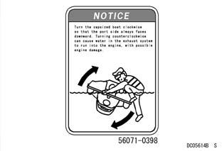
28 PREVENT MAJOR DAMAGE 27 Righting Capsized Watercraft Rolling the capsized watercraft counterclockwise (to its STARBOARD side) can cause water in the exhaust system to run into the engine, with possible engine damage. Always turn the capsized boat clockwise so that the PORT side always faces downward. For details on righting, refer to Righting the Capsized Watercraft section in the OPERATING IN- STRUCTIONS chapter. Shallow Water When starting the engine or riding, the watercraft must be in water at least 0.8 m (2.5 ft) deep. Sand or debris from the bottom may be drawn into the jet pump and damage the pump and impeller, and possibly clog cooling lines. j If operating in shallow or debris-laden water, objects or sand from the bottom can get sucked in damaging the impeller and possibly clogging cooling hoses which cancausesevereenginedamage from overheating. Avoid beaching the watercraft. Stones and sand can scratch the hull and be drawn into the jet pump, causing damage to the impeller.
29 28 PREVENT MAJOR DAMAGE Wave Jumping Jumping waves can overstress the watercraft hull and cause it to crack. To prevent hull cracks, do not jump waves. After daily riding Since JET SKI watercraft are not designed to be docked in water for extended periods, prolonged immersion will cause the hull paint to bubble and peel, as well as electrolytic erosion of some metal parts in the jet pump. To prevent this damage and electrolytic erosion, remove your JET SKI watercraft from the water at the end of each day s use; do not leave it in the water overnight. Your JET SKI watercraft will last longer and look better if you do this.
30 Jet Pump and Seals Periodic Maintenance The jet pump bearings and seals require periodic service. Major engine damage can occur if the jet pump bearings fail due to lack of maintenance. Have your Kawasaki dealer inspect the jet pump PREVENT MAJOR DAMAGE 29 bearings and seals after the first 25 hours of use or after one year, whichever comes first; and then every 50 hours or every year, whichever comes first. The jet pump bearings should also be serviced before any prolonged storage to prevent any water that may be left in the pump from corroding the bearings and causing premature failure. j

31 30 GENERAL INFORMATION GENERAL INFORMATION Parts Location A. Battery B. Rear View Mirror C. Front Storage Case D. Multifunction Meter E. Engine Start/Stop Button F. Throttle Lever G. Handlebars H. Center Storage Case I. Ignition Switch J. Engine Shut-off Lanyard K. Shift Lever L. Bow Eye


32 j GENERAL INFORMATION 31 A. Handrails B. Ski Tow Eye C. Seat Latch D. Rear Seat E. Front Seat F. Water Supply Inlet Fitting (inside hatch cover) G. Bypass Outlet H. Engine Compartment I. Hand Strap A. Stern Eyes B. Reboarding Step C. Reverse Bucket D. Exhaust Outlet E. Drain Screws F. Steering Nozzle


33 32 GENERAL INFORMATION A. Jet Pump Cover B. Water Intake C. Grate D. Drive Shaft E. Speed Sensor A. Air Box B. Exhaust Pipe C. Spark Plugs D. Fuel Injectors
34 Multifunction Meter Ahead of the handlebars is a multifunction meter. When the ignition switch is turned on, all displays on the panel are shown; the warning indicator light is on and buzzer will sound twice. After this self-check procedure, the meter display shows the normal readings. NOTE The display will go off 3 minutes after stopping the engine using the engine stop lanyard or stop button. GENERAL INFORMATION 33 The MODE button operates when the engine is running slower than rpm. When the warning light goes on, an intermittent buzzer sounds. This buzzer sound can be stopped by pushing either SET or MODE button. To turn off the blinking warning indicator lights, hold down either SET or MODE button for more than one second. Then the MODE buttoncanbeoperatednormally. j
 Maximum Speed & Engine rpm Water Temperature Outside Temperature Fuel Consumption 4. Engine Warning Indicator 5.")
35 34 GENERAL INFORMATION 1. MODE Button 2. SET Button 3. Multifunction Display Clock Time/Trip/Hour Meters Tachometer (Numerical Value) Maximum Speed & Engine rpm Water Temperature Outside Temperature Fuel Consumption 4. Engine Warning Indicator 5. Engine Cooling Water Temperature Indicator 6. Immobilizer Indicator 7. Warning Indicator Light (LED) 8. Low Battery Voltage Indicator 9. Engine Oil Pressure Indicator 10. Speedometer 11. Tachometer 12. Fuel Level Gauge
. On the right side of the tachometer face is a portion called the red zone.")
.")
36 Speedometer The speedometer shows the watercraft speed. During a sharp turn the speed shown can be 6 to 12 mph (10 to 20 km/h) lower than the actual speed. GENERAL INFORMATION 35 Tachometer The tachometer shows the engine speed in revolutions per minute (rpm). On the right side of the tachometer face is a portion called the red zone. Engine r/min (rpm) in the red zone is above maximum recommended engine speed and is also above the range for optimum performance. j A. Speedometer NOTE You can change the speedometer display from mile/h to km/h and vice-versa, see the Hour Meter section for details. The display range of the speed is 0 to 67 mph (0 to 108 km/h). If the speed exceeds 67 mph (108 km/h), the display is stopped and locked. When the speed is less than 3 mph (3 km/h), the meterdisplays0mph(0km/h). A. Tachometer B. Red Zone NOTICE Operating the engine at high rpm in the red zone will overstress the engine and may cause serious engine damage. To prevent engine damage, do not allow engine rpm to enter the red zone.

37 36 GENERAL INFORMATION Multifunction Displays The Clock, Time/Trip/Hour Meters, Tachometer, Maximum Speed & Engine rpm, Water Temperature, Outside Temperature and two Fuel Consumptions will be displayed under the speedometer. Pushing the MODE button, shifts the display. These modes will shift in series if the MODE button is pressed for 2 seconds or more. Clock 1. Push the SET button for 2 seconds or more. The hour display starts blinking. 2. Push the MODE button to advance the hours. 3. Push the SET button. The hour display stops blinking and the minutes display starts blinking. 4. Push the MODE button to advance the minutes. 5. Push the SET button. The minutes display stops blinking and the clock starts working.
38 NOTE Briefly pushing the MODE button advances the hours or minutes step by step. Holding the button down advances the hours or minutes continuously. The clock works normally from the back-up power whiletheignitionswitchisturnedoff. When the battery is disconnected, the clock resets to 12:00, and starts working again when a battery is connected. GENERAL INFORMATION 37 Time Meter The time meter shows the time elapsed since it was last reset to zero. To reset the time meter: 1. Push and hold the SET button. All the displays in this mode start blinking. 2. After two seconds the displays stop blinking and the hour and minute display turns back to 00:00, and then starts working, if the engine is running. The meter operates until it is reset. NOTE When the time reaches 99:59, it turns back to 00:00 and starts counting again. When the battery is disconnected, the time display resets to 00:00. j

39 38 GENERAL INFORMATION Trip Meter The trip meter shows the distance traveled since it was last reset to zero. To reset the trip meter: 1. Push the SET button and hold it in. All the displays in this mode start blinking. 2. After two seconds the displays stop blinking and the trip meter turns to 000.0, and then starts counting when the craft is operated. The meter operates until it is reset. NOTE The data is maintained by the back-up power if the ignition switch is turned off. The trip meter can be reset when the craft is stopped; it starts counting as soon as the craft starts moving. If the meter reaches when the craft is running, it will reset to and start counting again. When the battery is disconnected, the meter display resets to
40 j GENERAL INFORMATION 39 Hour Meter The hour meter shows the total hours that the watercraft has been operated. This meter cannot be reset. NOTE The data is maintained even if the battery is disconnected. When the figures reach 9999, they reset to 0000 and start counting upward again when the craft is operated. You can change the Hour Meter unit setting by pushing the SET button for more than 3 seconds. The units change in the following order.
41 40 GENERAL INFORMATION Maximum Speed & Engine rpm The maximum speed recorded since last reset and its corresponding engine rpm are shown. rpm symbol blinks in this mode. Tachometer (Numerical Value) The tachometer shows the engine speed in revolutions per minute (rpm). To reset this record: 1. Push the SET button and hold it. All the displays in this mode start blinking. 2. After two seconds the display stops blinking and reverts to 0.
 temperature in degrees Centigrade (or Fahrenheit) and the display is refreshed every 5 seconds.")
42 j GENERAL INFORMATION 41 Water Temperature This shows the ambient water temperature in degrees Centigrade (or Fahrenheit) and the display is refreshed every 5 seconds. Outside Temperature This shows the ambient (or outside) temperature in degrees Centigrade (or Fahrenheit) and the display is refreshed every 5 seconds.
43 42 GENERAL INFORMATION Fuel Consumptions This display shows the two types of fuel consumption by numerical value as follows. The first is the amount of fuel used per hour. The unit is L/h or GAL/h. Fuel Level Gauge/ FUEL Character/Warning Indicator Light The fuel level is shown in segments. All fuel segments are displayed when the fuel tank is full. As the fuel is consumed, the segments go out accordingly. When the last segment is reached, it begins blinking. The warning indicator light goes on, FUEL blinks and a buzzer sounds. To stop the buzzer, press any button for more than a second. When the low fuel indicator begins blinking, 28 liters (7.4 U.S. gal) of fuel remain. Reduce speed to less than half-throttle and fill the fuel tank as soon as possible because there is no reserve tank in this watercraft (See the Fuel and Controls sections). The second is amount of fuel used over a certain distance. The unit is L/km or GAL/m. The fuel consumption display is renewed every second.
44 GENERAL INFORMATION 43 Engine Oil Pressure Indicator/ OILP Character/Warning Indicator Light The warning indicator light goes on, the engine oil pressure indicator and OILP blink and a buzzer sounds whenever the oil pressure is dangerously low. The engine speed will automatically be limited to rpm. Return to shore immediately and fill the oil as soon as possible (See the Engine Oil section in the MAINTENANCE AND ADJUSTMENTS chapter). To stop the buzzer, press any button for more than a second. NOTE The oil warning indicator light will remain on after the watercraft is capsized and righted if the ignition keyison. j
45 44 GENERAL INFORMATION Engine Cooling Water Temperature Indicator/ HEAt character/warning Indicator Light If the engine cooling water temperature gets too high, the warning indicator light goes on, the engine cooling water temperature indicator and HEAt blink and a buzzer sounds to warn the operator. The engine speed will automatically be limited to rpm. Return to shore immediately and check the cooling system for clogging (seethespecialprocedures section in the Operating Instructions chapter). To stop the buzzer, press any button for more than a second. NOTICE To prevent engine damage, do not operate the craft until the cause of overheating is corrected.

46 Low Battery Voltage Indicator/ bat Character/Warning Indicator Light The warning light goes on, the low battery voltage indicator and bat blink and a buzzer sounds to warn the operator when the battery voltage is less than 11.5 volts. If the low battery voltage indicator blinks, return to shore immediately. Remove your watercraft s battery and charge it. To stop the buzzer, press any button for more than a second. GENERAL INFORMATION 45 Engine Oil Temperature Indicator/ OILt Character/Warning Indicator Light If the engine oil temperature sensor malfunctions, the warning indicator light goes on, the engine oil pressure indicator and OILt blink and a buzzer sounds. The engine speed will automatically be limited to rpm. Return to shore immediately and have your authorized Kawasaki JET SKI watercraft dealer check your boat to determine the problem. To stop the buzzer, press any button for more than a second. j
47 46 GENERAL INFORMATION Engine Oil Overheat Indicator/ OILH Character/Warning Indicator Light If the engine oil temperature gets too high, the warning indicator light goes on and the engine oil pressure indicator blinks and buzzer sound to warn the operator. Also OILH character starts blinking. The engine speed will automatically be limited to rpm. Return to shore immediately and check the cooling system for clogging and engine oil level. Ifthecauseisotherthanacloggedcoolingsystem or low oil level, have your authorized Kawasaki JET SKI watercraft dealer check your PWC to determine the problem (see the TROUBLE SHOOTING for instances when the engine speed will automatically be limited to rpm). To stop the buzzer, press any button for more than a second. Engine Warning Indicator/ FI Character/Warning Indicator Light If the fuel-injection-related parts malfunction, the warning indicator light goes on, the engine warning indicator and FI blink and a buzzer sounds to warn the operator. Return to shore immediately and have your authorized Kawasaki JET SKI watercraft dealer check your boat to determine the problem. To stop the buzzer, press any button for more than a second. Depending on the problem the engine speed will automatically be limited to rpm.
48 Immobilizer Amplifier Indicator/ Innb Character/Warning Indicator Light If the amplifier for the immobilizer system malfunctions, the warning indicator light, the immobilizer indicator and Innb blink and a buzzer sounds. Have your authorized Kawasaki JET SKI watercraft dealer check your boat. To stop the buzzer, press any button for more than a second. GENERAL INFORMATION 47 Immobilizer Key Matching Indicator/ I9nI Character/Warning Indicator Light If a key other than that registered to your watercraft is tried, the warning indicator light, the immobilizer indicator and I9nI blink and a buzzer sound. j
49 48 GENERAL INFORMATION Communication Trouble Indicator/ Err Character/Warning Indicator Light If there is a communication problem between the multifunction meter and the Electronic Control Unit (ECU), the warning indicator light goes on, the engine warning indicator and Err blink and a buzzer sounds. Have your authorized Kawasaki JET SKI watercraft dealer check your boat. To stop the buzzer, press any button for more than a second. Fuel NOTICE This watercraft has not been tested and certified for use with racing fuels or fuel additives. Their use may damage the engine and fuel system. Do not use race gas or fuel additives. Fuel Requirements Fuel Type Use clean, fresh unleaded gasoline with a minimum Antiknock Index shown in the tabel. The Antiknock Index is posted on service station pumps in the U.S.A. The octane rating of a gasoline is a measure of its resistance to detonation or knocking. The Antiknock Index is an average of the Research Octane Number (RON) and the Motor Octane Number (MON) as shown in the table below. Minimum Octane Rating Method Rating Antiknock Index (RON + MON) 2 87
50 NOTICE Engine knocking or pinging can lead to severe engine damage. If engine knocking or pinging occurs, use a different brand of gasoline of a higher octane rating. Gasoline quality is important. Fuels of low quality or not meeting standard industry specifications may result in unsatisfactory performance. Operating problems thatresultfromtheuse of poor quality or nonrecommended fuel may not be covered under your warranty. Fuels Containing Oxygenates Gasoline frequently contains oxygenates (alcohols and ethers) especially in areas of the U.S. and Canada which are required to sell such reformulated fuels as part of a strategy to reduce exhaust emissions. The types and volume of fuel oxygenates approved for use in unleaded gasoline by the U.S. Environmental Protection Agency include a broad range of alcohols and ethers, but only two components have seen any significant level of commercial use. GENERAL INFORMATION 49 Gasoline/Alcohol Blends - Gasoline containing up to 10% ethanol (alcohol produced from agricultural products such as corn), also known as gasohol" is approved for use. NOTICE Using blends of unleaded gasoline and methanol (wood alcohol) can damage the fuel system and result in poor engine performance. Avoid using methanol whenever possible, and never use gasohol containing more than 5% methanol. Gasoline/Ether Blends - The most common ether is methyl tertiary butyl ether (MTBE). You may use gasolinecontainingupto15%mtbe. NOTE Other oxygenates approved for use in unleaded gasoline include TAME (up to 16.7%) and ETBE (up to 17.2%). Fuel containing these oxygenates canalsobeusedinyourkawasaki. j

51 50 GENERAL INFORMATION NOTICE Using gasoline with an insufficient octane rating may damage the engine. To avoid engine damage, never use gasoline with an octane rating lower than the minimum specified by Kawasaki. Never use "gasohol" with more than 10% ethanol, or more than 5% methanol. Gasoline containing methanol must also be blendedwithcosolvents and corrosion inhibitors. Certain ingredients of gasoline may cause paint fading or damage. Be extra careful not to spill gasoline or gasoline oxygenate blends during refueling. When not operating your Kawasaki for 30 to 60 days, mix a fuel stabilizer (such as STA-BIL) with the gasoline in the fuel tank. Fuel stabilizer additives inhibit oxidation of the fuel which minimizes gummy deposits. Never store this product with "gasohol" in the fuel system. Before storage it is recommended that you drain all fuel from the fuel tank and fuel system. See the Storage section in this manual. Filling the Tank WARNING Gasoline is extremely flammable and can be explosive under certain conditions. To avoid a possible fire or explosion, pull the lanyard key off the stop button. Do not smoke. Make sure the area is well ventilated and free from any source of flame or sparks; this includes any appliance with a pilot light. Avoid filling the tank in the rain or where heavy dust is blowing so that the fuel does not get contaminated. The fuel tank is located at the front end of the engine compartment and the fuel filler cap is under the front storage lid. Open the lid and turn the cap counterclockwise and remove it. A. Fuel Filler Cap
52 GENERAL INFORMATION 51 When filling remove the seats and observe the fuel level in the fuel tank to avoid overfilling. Also observe the fuel level gauge on the meter for the segments to increase while filling. Fill the tank with the recommended octane rating gasoline. The use of a small diameter pour spout (or funnel) will make filling easier. Pour slowly to avoid "spit back" and allow air to escape from the tank. j WARNING Gasoline is extremely flammable and can be explosive under certain conditions. To avoid a possible fire or explosion never fill the tank completely to the top. As the fuel expands in a warm tank, it may overflow from the vent tube. After refueling, make sure the filler cap is closed securely. A. Fuel Tank B. Filler Neck C. Fuel Pump D. Top Level After transporting or refueling and before starting the engine, open the front storage compartment lid and remove the seats (see the Seat Latch section) for several minutes to ventilate the engine compartment. WARNING A concentration of gasoline fumes in the engine compartment can cause a fire or explosion. To prevent a fire or explosion, remove the seat to vent the engine compartment.
) and the other for normal operation")
53 52 GENERAL INFORMATION Ignition Switch Theignitionswitchislocated in the center storage case. This watercraft is equipped with two kinds of ignition keys, one of that controls the watercraft speed for the unskilled (Smart Learning Operation Mode, (SLO)) and the other for normal operation (Full Power Operation Mode (FPO)). These keys are equipped with an immobilizer system to protect your watercraft from theft. SLO/FPO Modes Depending on his/her skill, the rider can choose either Smart Learning Operation Mode (SLO), which reduces the maximum watercraft speed, or ordinary Full Power Operation Mode (FPO). Keys are color-coded. FPOinorangecolor SLO in yellow color and marked SLO A. FPO Key (Full Power Operation Mode: orange-colored) B. SLO Key (Smart Learning Operation Mode: yellow-colored and marked SLO) NOTE The ignition key is buoyant but if attached to an accessory or accessories that are heavier than water, it could sink. Do not attach an accessory or accessories to the ignition key that will not float in water. When FPO key is inserted, the multifunction meter will show the following display.

54 And when SLO key is inserted: GENERAL INFORMATION 53 Smart Learning Operation mode (SLO) This watercraft is equipped with SLO, which reduces the maximum watercraft speed by approximately 30 percent. SLO mode is displayed on the meter as SLO, whereas the non-restricted ordinary mode is displayed as FPO. In SLO mode, all the functions of the multifunction meter and KSS function remain the same as the ordinary FPO mode. To switch from FPO mode to SLO and vice versa, stop the engine and replace the ignition key from FPO to SLO and vice versa. See the Multifunction Meter section in this chapter. You should become familiar with the SLO mode so that you can assist others in understanding how it works. NOTE When shifted to the SLO mode, the initial display, as shown when the ignition switch is turned on, is shown and buzzer sounds. Then, SLO blinks every three seconds. When shifting to the normal operation mode (FPO), the same initial display is shown and a buzzer sounds followed by FPO for two seconds. However, FPO is shown only once and is not displayed thereafter. Under the SLO mode, all the meter displays and other functions work in the same manner as the normal operation (Full Power Operation, FPO) mode. j
 verifies the code of the immobilizer key and if the ECU recognizes the key, the warning indicator light goes on and a buzzer sounds and the initial display will be")

55 54 GENERAL INFORMATION How to use the Immobilizer-function keys Insert either the SLO or FPO key into the key slot in the center storage case and press the key further in. The ECU (electronic control unit) verifies the code of the immobilizer key and if the ECU recognizes the key, the warning indicator light goes on and a buzzer sounds and the initial display will be shown on the multifunction meter. You can now start the engine. Three minutes after the engine stops, the meter display disappears and the ignition switch is turned off. When turning on the ignition switch again, push the ignition key forward. A. Key Slot B. Immobilizer Key NOTE When shifting the mode from SLO to FPO and vice versa, be sure to stop the engine. If the engine is on, the mode cannot be shifted. A. Push Be sure the key remains in the slot while riding the watercraft. If you lose the keys at sea you will be unable to start the engine again and may end up stranded. Observe the following precautions to protect your immobilizer keys.
56 NOTICE The keys can be damaged by excessive heat, magnetic fields, heavy objects, shocks and if the plastic cover is damaged. To prevent key damage, do not expose the keys to excessively high temperatures, place them close to magnets or under heavy items, and avoid damaging the plastic covers. If an unregistered key is tried, an alarm sounds and a warning indicator light blinks on the multifunction meter. An alarms also sounds if the immobilizer system malfunctions. See Multifunction Meter section in this chapter. NOTE Since the immobilizer system uses an electric wave for communication, keep away from other sources of electricity to prevent key identification errors. Whenever the watercraft is not in use, be sure to remove the key from the key slot to prevent unauthorized use. Lost Keys If you lose a key, contact a Kawasaki dealer to obtain a new one. Take the watercraft to the dealer to have the new key registered to the ECU. You need GENERAL INFORMATION 55 at least one registered key to have a new key registeredtotheecu.ifyoulosebothregisteredkeys, you have to replace the ECU, so always keep a spare key in a safe place. NOTE There is a limit to the number of keys that can be registered to the ECU. Declaration of conformity FCC Warning Changes or modifications not expressly approved by the party responsible for compliance could void the user s authority to operate the equipment. This device complies with Part 15 of the FCC Rules and RSS-Gen of IC Rules. Operation is subject to the following two conditions: (1) This device may not causes harmful interference. (2) This device must accept any interference received, including interference that may cause undesired operation. j

57 56 GENERAL INFORMATION Controls Handlebars Tilt Lever The handlebar tilt can be adjusted to suit you. Push down the tilt lever and move the handlebars up or down. There are five different angles to choose from. A. Handlebars The handlebars allow the rider to steer the watercraft. It will turn ONLY WHEN THE ENGINE IS RUNNING AND ONLY WHEN THE THROTTLE IS APPLIED. The handlebars are connected by a control cable to the jet pump steering nozzle at the rear of the boat. A. Steering Handlebars B. Tilt Lever WARNING Adjusting the handlebar position while riding may cause the handlebars to suddenly change position, causing loss of control and an accident resulting in injury or death. To help prevent accidents, never touch or attempt to adjust the handlebar position while operating the watercraft; do so only when stopped.
58 Kawasaki Smart Steering TM (KSS TM ) Your JET SKI watercraft can turn under certain conditions when the throttle is released. There must be thrust at the jet nozzle to initiate and complete turns. This is a supplemental steering system which assists operators in learning to negotiate turns and maneuver. Your JET SKI watercraft continuously detects the operator s steering input as well as boat speed. When the throttle is released while boat speed is high and a turn is initiated, your JET SKI watercraft automatically increases engine speed to provide additional thrust. The system does not work when the engine is off or boat speed is low. GENERAL INFORMATION 57 Important Information When you make an emergency maneuver YOU MUST HAVE THRUST TO TURN, so keep the throttle on or apply throttle as needed to maintain thrust. You can turn quicker by applying the throttle as needed and not relying upon KSS. The system functions when all of these conditions are present: engine speed averages more than RPM for a specified time the throttle is released completely and the handlebars are held fully to the left or right. Stop Button Thestopbuttonisinthecaseonthelefthand side of the handlebars. It is red and marked STOP. Pushing the stop button turns off the engine. The engine is also stopped by pulling the engine shut-off lanyard key off the stop button. After riding, remove the engine shut-off lanyard key from the watercraft to avoid unauthorized use by children or others. Engine Shut-off Lanyard Key Keep the engine shut-off lanyard key attached to the operator s left wrist. Insert the engine shut-off lanyard key to the stop button before starting the engine. The engine stops automatically when the lanyard is removed. j
59 58 GENERAL INFORMATION NOTICE Do not push the START button while the engine is running or while the starter is still spinning as this causes premature starter wear and may cause it to jam. NOTE For the engine to start, the ignition key must be inserted and the engine shut-off lanyard key must be pushed under the stop button. Refer to the Starting the Engine section in the Operating Instructions chapter. A. Stop Button B. Lanyard Key After riding, remove the engine shut-off lanyard key from PWC to avoid unauthorized use by children or others. NOTE For the engine to start, the ignition key must be inserted and the engine shut-off lanyard key must be pushed under the stop button. Start Button The start button is in the case on the left hand side of the handlebars. It is green and is marked START. Pushing the start button with the engine shut-off lanyard key pushed under the stop button starts the engine. Release it when the engine starts. A. Start Button B. Lanyard Key

60 Throttle Lever The throttle lever is located on the right handlebar grip. Squeezing the lever towards the handlebar grip increases engine speed. When released, spring pressure returns the lever to the idle position. Always check that the throttle lever returns normally before starting the engine. In addition, there must be adequate throttle cable play. Refer to the MAINTE- NANCE AND ADJUSTMENTS chapter for the throttle cable adjustment procedure. GENERAL INFORMATION 59 To shift into Reverse from Forward, squeeze the trigger on the lever while pulling the lever all the way up. j A. Throttle Lever Shift Lever The shift lever is located on the left side under the handlebars and has two positions: F (Forward) and R (Reverse). A. Shift Lever B. Trigger To shift into Forward, squeeze the trigger while pushing the lever all the way down. Be sure to allow the watercraft to slow down before shifting from Forward to Reverse. Refer to the Operating the JET SKI Watercraft in Reverse sectionintheoperatinginstruc- TIONS chapter.

61 60 GENERAL INFORMATION WARNING Suddenly shifting into reverse at high speed can cause the bow to suddenly dive into the water, throwing the occupants forward which can cause severe injury. Do not shift into reverse while going forward and do not use reverse as a brake. Slow the watercraft to a stop and alert any passengers before shifting to reverse. Seat Latches Therearetwoindividual seats that can be unlocked using the latch under the rear of each seat. Remove the rear seat first. The procedure to open and close is the same for both seats. To Open: Pull the latch handle and pull the seat up and to the rear. To Close: Position the front of the seat in place, slide it all the way forward and then push down on the rear of the seat to lockit. A. Rear Seat B. Latch Handle


62 GENERAL INFORMATION 61 Storage Compartment The box type storage case is located in the bow. Store this Owner s Manual there in a plastic bag. To open the lid, pull the knob and raise the lid all the way up. To close the lid, push on it near the knob until it latches. j A. Front Seat B. Latch Handle When transporting the watercraft, make sure the seats are secured to prevent them from becoming dislodged and damaged or lost. NOTE Check that the seat latch is locked securely before you board the watercraft. A. Front Storage Lid B. Knob WARNING Storing fuel in the front storage compartment can cause a fire or explosion that can result in injury or death. Do not store fuel or other flammable liquids in this unventilated compartment.
 A. Battery (Fuse) Cover B. ECU Cover A. Front Storage Case B.")

63 62 GENERAL INFORMATION A container for a fire extinguisher is attached to the storage case. (A fire extinguisher is not standard equipment with this watercraft.) A. Battery (Fuse) Cover B. ECU Cover A. Front Storage Case B. Fire Extinguisher Remove the storage case, and you will find another space in the bow where the battery and the fuse are located. NOTICE Running the watercraft without the storage case will cause water to enter the storage compartment. To prevent flooding, the storage case should always be in position while riding. NOTE Make sure the storage compartment lid is properly securedbeforeridingthewatercraft.


64 GENERAL INFORMATION 63 Center and Rear Storage Cases There is a center storage case in front of the seat. The ignition switch is inside this case. To open the lid, pull the knob. To close the lid, push the knob until it latches. j A. Rear Storage Case B. Drain Plugs A. Center Storage Case B. Knob The box type rear storage case is located under the rear seat. Only keep light items in these storage cases.

65 64 GENERAL INFORMATION Tool Kit The tool kit container is stored at the back of the rear seat. Unhook the rubber straps to remove the tool kit. Bilge Systems This watercraft has a jet vacuum drainage system at the rear end of the engine compartment. This system utilizes the water jet for propulsion to drain the bilge in the engine compartment. This system only works when the engine is running on water. NOTICE Check that the bilge system is working at regular intervals according to the Periodic Maintenance Chart. Refer to the MAINTENANCE AND ADJUSTMENTS chapter. Clear debris from the pump intakes. A. Tool Kit B. Rubber Straps WARNING Damage to the hull may cause a leak and the capacity of the bilge pumping system is not designed to drain the hull in such instances. To avoid sinking the watercraft, immediately return to shore if the hull is damaged in any way. NOTE To drain any water remaining in the bilge, remove the drain screws at the rear end when the craft is outofthewater.
66 GENERAL INFORMATION 65 Drain Screws There are two drain screws in the stern to drain water accumulated in the engine compartment. Open them only when the craft is out of the water. NOTICE If the screws come loose the craft may flood or become swamped, with the possibility of sinking or severe engine damage. To prevent swamping, be sure the screws are securely tightened before launching. Handrail The handrail behind the seat is for boarding from deep water. Also, when towing a water skier, wakeboarder, or tuber, the handrail should be held by the observer who faces rearward to watch the water skier, wakeboarder, or tuber. It is not designed for any other purpose. See the Towing (a wakeboarder, water skier, tuber, etc.) section in this chapter. WARNING Do not lift the watercraft using the handrail. The watercraft could fall and result in severe injury. NOTICE To prevent damage to the handrail and/or hull, do not use the handrail behind the seat for towing or attaching tie-downs. j A. Drain Screws

67 66 GENERAL INFORMATION Reboarding Step The watercraft is equipped with a folding type reboarding step at the stern. When reboarding from the rear of the craft, pull the step down. It automatically raises back to the original position when released. You can reboard more easily from the water by using this step and the handrail behind the rear end of the seat (see the Safe Operation and Launching sections in the OPERATING INSTRUC- TIONS chapter). This step is designed only for reboarding from deep water, do not use it for pulling other craft. WARNING Do not use the reboarding step while the engine is running. Do not use the reboarding step to pull anyone or anything. Improper use can result in serious injury. A. Reboarding Step B. Handrails
68 Loading/Accessories/Modifications WARNING Incorrect loading, overloading, use of accessories and/or modification of your watercraft mayaffectitsstabilityandhandlingandresult in an unsafe riding condition. Before you ride the watercraft, make sure that it is not overloaded and that you have followed these instructions. Maximum load Maximumload:225kg(496lb) Ensure the total weight of riders and luggage aboard the watercraft does not exceed the maximum load. Ensure the storage spaces are not overloaded. Storage space Rear deck Accessory case Storage pocket (front) Storage pocket (rear) Load limit 23 kg (50 lb) 8kg(17.6lb) 1.3kg(2.9lb) 1.3 kg (2.9lb) Important Information Accessories: Kawasaki has no control over the design or application of accessories. In some cases, GENERAL INFORMATION 67 improper installation or use of accessories, or watercraft modification, will void the warranty. Using non-genuine accessories or modifying your watercraft may threaten your own safety and the safety of others. NOTE Kawasaki Parts and Accessories have been specially designed for use on Kawasaki watercraft. We strongly recommend that all parts and accessories you add to your watercraft be genuine Kawasaki components. Because a personal watercraft is sensitive to changes in weight distribution, you must take extreme care in carrying cargo, passengers and in the fitting of additional accessories. Use the following guidelines when carrying passengers and cargo. Passengers can affect control of the watercraft by improper positioning or sudden movements. It is important that passengers sit still while the watercraft is in motion and not interfere with its operation. Do not carry animals on your watercraft. Instruct any passengers before riding to hold on to the person in front of them or hand strap, and keep both feet on the deck for balance. Use the open storage area behind the seat for carrying cargo. Be sure that any loose items are packed in a buoyant container to prevent them from falling overboard and sinking. Loose articles or rope could fall overboard and become lodged in the intake grate or pump. j
.")
69 68 GENERAL INFORMATION Use a cargo net (not standard equipment with this watercraft) or other suitable tie-down straps to secure cargo on the open storage area. The hook under the rear end of the seat and the stern eyes are also available. Do not overload the storage area, maximum cargo weight must not exceed 23 kg (50 lb). often as possible and adjust as necessary. Make sure that the cargo will not move around while you are riding. Recheck cargo security as Do not carry large or bulky items that affect visibility or your ability to control the watercraft. Do not install accessories or carry cargo that impairs the performance of the watercraft. WARNING Cargo in the open storage area could interfere with reboarding by causing a loss of balance and possible injury. Do not stack cargo in such a way that it interferes with reboarding. A. Ski Tow Eye B. Open Storage Area C. Hand Strap D. Stern Eyes
70 Towing (a wakeboarder, water skier, tuber, etc.) Towing a wakeboarder/water skier/tuber Towing a wakeboarder, water skier, or tuber is a three-person team sport involving the watercraft operator, the backward-facing observer and the wakeboarder/skier/tuber. Everyone must know their equipment, boating laws and regulations, respective responsibilities, communication signals and the fundamentals of the sport. GENERAL INFORMATION 69 WARNING All riders and wakeboarders/skiersr/tubers must wear a vest-type PFD (personal floatation device) and wetsuit bottom or equivalent to protect against possible injury to body cavities from forced injection of water. Normal swimwear will not provide adequate protection, possibly leading to severe injury. Avoid collisions with other boats, fixed objects or swimmers by staying out of congested areas. Keep your watercraft at least 2.5 times the length of the tow rope away from the shore, shallow water, obstacles, etc. (at least 50 m if the tow rope is 20 m long). around body parts. To avoid serious injury, such as amputation to body parts, do not wrap the tow rope Your watercraft is not designed to tow any object that may float in the air while being towed. Do not use your watercraft for any such applications, or injuries may result. Before towing, ensure that all members of the team understand the meaning of every communication signal. Observe the local rules and regulations in the area where you are using the watercraft. Tie the tow rope only to the ski tow eye under the rear end of the seat. Be extra careful when towing; j

71 70 GENERAL INFORMATION towing can affect the steering of your watercraft and create a hazardous situation. A. Ski Tow Eye Roles of the watercraft operator The operator is responsible for the behaviour and safety of the team. Towing requires good operating skills. Do not attempt to tow before you have become proficient at controlling your watercraft. Start off by idling ahead until the tow rope is tight. When the wakeboarder/skier/tuber signals he or she is ready, be sure the water around the watercraft is clear and gradually increase the speed to raise the wakeboarder/skier/tuber. Maintain a speed that matches the skill of the Avoid rapid accelera- wakeboarder/skier/tuber. tion and abrupt turns. If the wakeboarder/skier/tuber falls, cautiously return to him/her. Stop towing when any part of the body of the observer and/or wakeboarder/skier/tuber is in contact with the tow rope or when they are not in a stable position. Be extremely observant when towing a wakeboarder/skier/tuber. Other boat operators may not be expecting your watercraft to be pulling anything behind it. Coordinate with the observer to ensure utmost safety when towing. Roles of the observer The observer must keep an eye on the wakeboarder/skier/tuber, relay all signals from him/her to the operator and inform the operator immediately if he/she falls, and display the ski flag. The observer should firmly hold the handrail behind the seat while facing rearward to watch the wakeboarder/skier/tuber being towed. Before towing, check that the tow rope is not wrapped around the wakeboarder/skier/tuber, or riders. The observer must look after the tow rope to prevent it from entering the water intake. Towing a personal watercraft If your watercraft runs out of fuel, develops engine problems, or needs to be towed by another watercraft, or if your watercraft needs to tow another watercraft in similar situations, tie a tow rope to the following location(s). Use a rope which is long enough to keep 6 m or more distance between towing and


72 towed boats. Towing must be slow, not exceeding 8 km/h. Be extra careful when towing; towing can affect the steering of your watercraft and create a hazardous situation. WARNING Towing heavy items can make the watercraft difficult to control and result in an accident. Towing a watercraft Attach the tow rope to the stern eyes. GENERAL INFORMATION 71 NOTICE When your watercraft is being towed by another watercraft, ensure that at least one person is on board your watercraft. If it is towed with no one on board, it can tip over sideways when hit by waves, or the lighter stern can cause the heavier bow to enter waves, resulting in water entering the engine compartment and causing part of the watercraft to submerge. The rider(s) must keep the balance of the watercraft while being towed. j A. Stern Eyes Being towed by a watercraft Attach the tow rope to the bow eye. A. Bow Eye After towing, drain any water in the engine compartment and check that no water enters the engine following the procedure described in the After Submerging section.
73 72 PRE-RIDE CHECK PRE-RIDE CHECK Each day before using the watercraft, check the following items: WARNING BE SURE TO PERFORM A PRE-RIDE CHECK each day before using watercraft for safety. Check Outside Craft CLEAN PUMP - Clear the water intake, jet pump, and drive shaft of foreign objects. PUMP COVER TIGHT - Check the jet pump cover and intake grate for looseness. Tighten the mounting bolts if necessary. HULL DAMAGE - Inspect the hull for damage. DRAIN SCREWS - Check that the drain screws in the stern are securely installed. CheckInsideCraft STEERING - Check the operation of the steering for binding, rough spots, or excessive play. Adjust the cable if needed (see the Control Cables section in the MAINTENANCE AND ADJUSTMENTS chapter). The steering cable is sealed at both ends and does not need lubrication. If the seals are damaged, the cable must be replaced. SHIFT LEVER - Check the operation of the shift lever for binding, rough spots or excessive play. Adjust the cable if needed (see the Control Cables section in the MAINTENANCE AND AD- JUSTMENTS chapter). THROTTLE CONTROL - Check the operation of the throttle for binding, rough spots or excessive play. Adjust the cable if needed (see the Control Cables section in the MAINTENANCE AND AD- JUSTMENTS chapter). The throttle lever must return to the fully closed position when released. WARNING A stuck throttle can cause loss of control and an accident resulting in injury or death. If the throttle does not return freely and completely, do not ride and have it inspected by your Kawasaki dealer. VENTILATE ENGINE COMPARTMENT - Open the front storage case lid, remove the seats and keep open for several minutes to purge gasoline fumes from the engine compartment. WARNING A concentration of gasoline fumes in the engine compartment can cause a fire or explosion. To prevent a fire or explosion, remove the seat to vent the engine compartment.
74 BATTERY TERMINALS - Check the battery terminal screws for tightness, and make sure terminal covers are in place. WARNING Loose battery cables can create sparks which can cause a fire or explosion resulting in injury or death. Make sure the battery terminal screws are tightened securely and the covers are installed over the terminals. FIRE EXTINGUISHER - Check the fire extinguisher is fully charged. FUEL PRESSURE - Loosen the fuel tank cap to relieve any pressure, then tighten the cap securely. FUEL LEVEL - Check the fuel level. Refill if necessary. ENGINE OIL LEVEL - Check the oil level in the engine. Refill if necessary. Refer to GENERAL INFORMATION CHAPTER, Engine Oil section. FUEL LEAKS - Check the engine compartment for fuel leaks. OIL LEAKS - Check the engine compartment for oil leaks. FASTENERS - Check and tighten any loose bolts, nuts, or clamps. HOSE CONNECTIONS - Be sure all hose connections are secure and that all hose clamps are tight. Check all hoses for cracks or deterioration and replace if necessary. PRE-RIDE CHECK 73 DANGER DRAIN BILGE - Drain any water out of the engine compartment by removing the drain screws. Install the drain screws securely when all the water has been drained. ENGINE SHUT-OFF LANYARD KEY - Start the engine and run it for a few seconds (see the Starting the Engine section). Pull the lanyard key off the stop button to check that the engine stops immediately. Exhaust gas contains carbon monoxide, a colorless, odorless poisonous gas. Inhaling carbon monoxide can cause serious brain injury or death. DO NOT run the engine in enclosed areas. Operate only in a well-ventilated area. NOTICE To prevent overheating resulting in engine and exhaust system damage, do not run the engine with the watercraft out of the water for more than 15 seconds at a time. Never operate the engine at maximum speed out of the water. STOP BUTTON - Again start the engine, run it for a few seconds, and then check that the engine STOP button works. SEATS - Check that the seat latches are secure. j
75 74 PRE-RIDE CHECK STORAGE COMPARTMENT - Check that the lid is secure. RIDER PROTECTION - Always wear the proper flotation device and protectivegear. MULTIFUNCTION METER - Check the operation of the multifunction meter. See GENERAL IN- FORMATION chapter for details.
76 OPERATING INSTRUCTIONS OPERATING INSTRUCTIONS 75 Basic Knowledge for Operation Read SAFETY INFORMATION and PREVENT MAJOR DAMAGE without fail. Please be sure to conduct the PRE-RIDE CHECK before boarding. Operation by unskilled riders This watercraft is equipped with the Smart Learning Operation mode (SLO), which reduces the maximum watercraft speed by approximately 30 percent. Unskilled operators should practice operation of the craft using the SLO mode until they become more familiar with its operation. See the Ignition Switch in the GENERAL INFOR- MATION chapter. On your first ride, familiarize yourself with the handling of the craft. Vary the engine speed with the throttle lever to get the feel of throttle influence on steering. Operator Swimming Ability Riders of personal watercraft can fall into the water and experience exposure. Operator and passengers must be competent swimmers and never travel farther from shore than they can swim. Maximum Number of Persons This watercraft is designed to carry the operator and up to 2 passengers. Never exceed the maximum load limit 225 kg (496 lb) or allow more than 3 persons (or 2 persons if a water-skier is being towed) to ride the watercraft at a time (See the Loading/Accessories/Modifications section in the chapter). WARNING Overloading this watercraft can adversely affect handling and stability which can lead to an accident. To reduce the risk of having an accident, do not exceed the maximum recommended number of people. Regardless of the number of people on board, the total weight including cargo must never exceed the load capacity limit. Passengers should always use the seats. Safe Riding Rules Always follow these rules when operating your watercraft, for your own safety and that of others. Always comply with any Navigation Rules in effect in your area. The Coast Guard office or state boating authority nearest you can usually furnish you with the applicable rules. Check local and j
77 76 OPERATING INSTRUCTIONS state regulations before operating. Kawasaki recommends that all operators complete an approved boating safety course. Personal Flotation Device and Safety Gear U.S. federal regulations require that one U.S. Coast Guard approved personal flotation device (PFD) be carried for each person aboard when operating on water under Coast Guard jurisdiction. In some state waters not under federal jurisdiction, other flotation devices are permissible in addition to those specified by federal law. Other countries may have their own standards and regulations; be sure to follow them. As a rule, waist-type ski belts do not qualify as adequate flotation devices. The full vest type is recommended. Check local regulations to see what type of personal flotation device may be required in your area. Drowning Hazard: a personal flotation device (PFD) must be worn by the operator and passengers. Kawasaki recommends that the operator and passengers wear a vest-type PFD (type 1, 2 or 3) at all times.
78 WARNING OPERATING INSTRUCTIONS 77 All riders must wear a Coast Guard approved personal flotation device (PFD) that is suitable for personal watercraft (PWC) use. Kawasaki recommends a vest-type PFD. Hard impact with the water can result in unconsciousness and/or drowning. Make sure that your PFD fits correctly and tightly so that it does not come off in the water. Never use an adult size PFD for children. Severe internal injuries can occur if water is forced into body cavities as a result of falling into water or being near the jet thrust nozzle. Normal swimwear does not adequately protect against forceful water entry into the rectum or vagina. All riders must wear a wet suit bottom or clothing that provides equivalent protection. Wet suits are made of a thick material (neoprene) that significantly retards the velocity of water passing through it. Normal swimwear will not adequately protect you but some other aquatic wear may protect against this injury. Swimsuits that may be displaced by the force of the water will not provide that protection. Materials that are thicker, materials that are a tighter weave, materials that are water repellant, and materials that are closer fitting will tend to provide more protection. In the absence of wearing a wet suit bottom, you should select a clothing design that will maximize your protection. Wear protective footwear, gloves and goggles (glasses). j
79 78 OPERATING INSTRUCTIONS Watercraft Helmet... Something You Should Know A helmet helps protect your head, but could contribute to neck injuries. Before wearing a helmet on a personal watercraft you must weigh the benefits and risks. Benefits: Helmets offer some head protection from impacts with hard objects. Risks: Helmets could reduce peripheral vision and increase fatigue; both of which could lead to a collision. Helmets could also increase loads on the neck and throat if you fall into the water, which could result in severe injuries. You must decide. Ifyouplantorideunder conditions in which you believe there is a higher chance that your head may be hit by a hard object, such as falling during a race, you may choose to wear a helmet and accept the risks. On the other hand, if head impact with the water is more likely, you may choose to not wear a helmet. Fire Extinguisher A charged and functional fire extinguisher must be carried on board, and may be stored in the storage compartment (see the Storage Compartment section in the GENERAL INFORMATION chapter). Be sure to install the fire extinguisher securely. Because the watercraft is an inboard boat less than 4.8 m (16 ft) in length, federal regulations require that a fire extinguisher rated B-1 (minimum 1 kg or 2 pound capacity) be aboard when operating on navigable waters under Coast Guard Jurisdiction. In addition, most states, parks, and wildlife departments require that a U.S.C.G. approved fire extinguisher be carried aboard, even on waters not under federal jurisdiction. Other countries may have their own standards and regulations; be sure to follow them. WARNING A fire aboard the watercraft may cause burns, melt the hull and cause it to sink, leaving the operator and passengers stranded. To prevent any fire from consuming the watercraft,alwayscarryafireextinguisher.
.")
80 Standard equipment does not include a fire extinguisher. Many owners prefer to provide their own fire extinguishers. If you wish, your dealer can furnishyouwithanapproved Kawasaki accessory fire extinguisher (P/N. W A). Weather condition OPERATING INSTRUCTIONS 79 Before operating your watercraft, check with local weather reports and US Coast Guard. NOTE Generally, weather can change more suddenly over the sea than over the land, so pay close attention to the weather when using the watercraft. If you notice any signs of strong wind or fog, immediately return to shore. WARNING Do not operate the watercraft in adverse weather condition or in wild waves. It could lead marine peril. Slow down before crossing waves. Crossing wild waves at high speeds could increase the risk of back/spinal injury (paralysis), facial injuries, and broken legs, ankles, and other bones. The operator must judge what is a safe speed taking into consideration visibility, traffic, weather conditions, waves, etc. Water conditions such as converging waves can have considerable influence on the ride characteristics of a personal watercraft and can cause the operator and passengers to fall off. Additionally, attempting to achieve maximum speed in adverse conditions can cause j
81 80 OPERATING INSTRUCTIONS abrupt movement of the boat causing possible injury to the riders. Basic Operating and Riding Posture on the Seats When riding the watercraft, sit astride the seat. WARNING Rough water can cause the watercraft to suddenly rise, creating the potential for the handlebar to strike and injure a rider who is positioned too close. To avoid injury, never ride with any part of your body immediately above the handlebar. If porpoising occurs, that is, the front of the craft rises and falls rapidly, move your body weight further forward. Operation with Passengers Before starting, the operator should ensure passengers are sitting properly astride the seats. They should hold on to the person in front of them or a hand strap while keeping both feet on the deck for balance when travelling or they could fall and injure themselves. The driver should warn passengers before opening the throttle and should not try to throw passengers off.
82 Never allow the passenger to ride in front of the operator. Do not carry children unless both feet are able to reach the deck. Boarding from Water Solo Operation Move to the rear of the watercraft. Make sure the engine is stopped. Grasp the handrail on the rear of the seat, pull the reboarding step down, and while placing one knee and then one foot or both feet on the step, pull yourself up onto the deck. Place one knee on the deck rear end, then the other. Be careful not to slip on the step or boat as you reboard. Grasp the hand strap and while balancing the craft place your feet on the deck. Sit astride the seat. OPERATING INSTRUCTIONS 81 Operator and Passengers While the operator is balancing the craft, the passengers climb aboard from the rear of the craft in the same way as in Solo Operation. WARNING The reboarding step is adjacent to the jet pump nozzle, and water and/or debris ejected from the jet thrust nozzle can cause severe injury. To avoid injury, The operator should always stop the engine and pull the engine shut-off lanyard key before a passenger uses the reboarding step. The passenger should not use the reboarding step while the engine is running. Boarding from a Dock Do not jump onto the watercraft from the dock. First place one foot on the deck near the dock, then while holding the handlebar and balancing the craft by transferring body weight straddle the craft and sit down on the seat. Break-In A new watercraft should be ridden with care during the break-in period to allow mechanical components to bed-in and produce smooth, long wearing surfaces. j
83 82 OPERATING INSTRUCTIONS Do not exceed the engine speeds listed below during the break-in period. During the first five minutes: During the next hour: During the next 30 minutes: Maximum rpm Maximum rpm Maximum rpm Careful treatment of the craft during the break-in period will result in more efficient, reliable performance and a longer life for the craft. In addition to the break-in described above, we recommend that the owner take his watercraft to an authorized Kawasaki JET SKI watercraft dealer after the first ten hours of operation for initial maintenance service. See the Periodic Maintenance Chart in the MAINTENANCE AND ADJUSTMENTS chapter. Stopping the Engine The engine can be stopped in one of the following two ways. Push the red STOP button. It is not necessary to hold the button in to stop the engine. After the engine stops, the STOP button resets itself and the engine is ready to start. Pull the engine shut-off lanyard key off the stop button. To start the engine the lanyard key must be pushed under the stop button. Remove the ignition switch key after stopping the engine in either case. WARNING A JET SKI watercraft requires throttle (thrust) to steer and help you to avoid objects - you have no directional control when the engine is stopped. To avoid objects the engine must be running and throttle applied to steer away from objects. Always check the throttle and steering controls for proper operation before starting the watercraft. A. Stop Button B. Lanyard Key If the engine must be stopped immediately in an emergency, push the red STOP button or pull the engine shut-off lanyard key off the stop button. Some possible EMERGENCY situations are: The engine speeds out of control.
84 The throttle lever does not release completely. WARNING A JET SKI watercraft requires throttle (thrust) to steer and help you to avoid objects - you have no directional control when the engine is stopped. If the throttle fails, do not operate the watercraft until the source of the problem is found and corrected. WARNING After riding, remove the ignition switch key and engine shut-off lanyard key from the watercraft to avoid unauthorized use by children or others. NOTICE A discharged battery will not provide power to start the engine. To prevent the battery from discharging, always turn the ignition switch OFF after stopping the engine. OPERATING INSTRUCTIONS 83 After transporting or refueling and before starting the engine, open the front storage compartment lid and remove the seats for several minutes to ventilate the engine compartment. WARNING A concentration of gasoline fumes in the engine compartment can cause a fire or explosion. To prevent a fire or explosion, remove seat for several minutes to purge gasoline fumes from engine compartment. Place the watercraft in at least 0.8 m (2.5 feet) of water which is clear of weeds and debris. Make sure the area ahead of the watercraft is clear of swimmers, boats, and obstacles. j Starting the Engine Read the PRE-RIDE CHECK chapter in this manual and follow its instructions before putting the watercraft in the water.
85 84 OPERATING INSTRUCTIONS NOTICE When starting the engine or riding, the watercraft must be in water at least 0.8 m (2.5 ft) deep. Sand or debris from the bottom maybedrawnintothejetpumpanddamage the pump and impeller, and possibly clog cooling lines. If operating in shallow or debris-laden water, objects or sand from the bottom can get sucked in damaging the impeller and possibly clogging cooling hoses which can cause severe engine damage from overheating. Avoid beaching the watercraft. Stones and sand can scratch the hull and be drawn into the jet pump, causing damage to the impeller. In the seated position push the lanyard key under the stop button and put your left hand through the other end of the lanyard to attach it to your wrist. Pull the lanyard to make sure it is securely attached and keep it free from the handlebars so that the engine stops if the driver falls off. NOTE The engine neither cranks nor starts with the lanyard key removed from the stop button. Insert the ignition key into the key slot in the center storage case and press the key further in. If the engine is not started within three minutes, the ignition switch turns off automatically. NOTE This watercraft is equipped with two kinds of ignition keys, SLO and FPO. Choose an appropriate key depending on your skill. These keys are equipped with an immobilizer system. Only use coded and registered keys. Refer to the Ignition Switch section in GENERAL INFORMATION chapter for more details. The watercraft is equipped with a vehicle-down sensor, which causes the engine to stop automatically and the warning indicator light to illuminate and the FI indicator and the FI character blink when the watercraft has capsized and the start button pushed in. When the watercraft has capsized and been righted within 3 minutes, push the start button to start the engine. If the watercraft has capsized for more than 3 minutes, after righting the watercraft, first push the key and then push the start button to start the engine. Be sure to keep the key inserted in the slot while riding the watercraft. This is important because if you lose the keys at sea you will be unable to start the engine again and may end up being stranded. With your left hand, push the green start button and release it when the engine starts. If the engine does not start within 5 seconds, release the button. Wait 15 seconds before trying again. If the engine does not start after several attempts, see the IN AN EMERGENCY chapter.

86 j OPERATING INSTRUCTIONS 85 After the engine has started,allowittowarmupfor about 1 minute. Apply a little throttle occasionally. Excessive idling can foul the spark plugs. Check that water comes out of the bypass outlet in the right side of the hull when the throttle is applied. This indicates that cooling water is circulating. If there is none, shut off the engine and find the source of the problem. When the exhaust system is dry, it can take up to 15 seconds for water to appear at the bypass outlet. A. Start Button B. Lanyard Key NOTE Wait 15 seconds between each operation of the starter. This will extend battery and starter life significantly. NOTICE Do not push the START button while the engine is running or while the starter is still spinning as this causes premature starter wear and may cause it to jam. A. Bypass Outlet
87 86 OPERATING INSTRUCTIONS Launching Launching/Start Launching Before putting the watercraft in the water, be sure youhavefollowedthepre-ridechecklist. Before launching, check the ramp for suitable surface conditions, inclination and width for both the trailer and tow vehicle. NOTICE Ensure the drain screws are securely tightened before launching to prevent flooding which may cause sinking or severe engine damage. Attach a bow line to the watercraft and detach the trailer tie-downs. Wait until it s your turn then back the trailer to the water. Unlockthewinchandpushthecraftslowlyoffthe trailer into the water. Move your watercraft to a docking or loading area and park your tow vehicle. Do not block the ramp. Start Check that the shift lever is in the F position to go forward or R for reverse. When leaving the dock, either push the watercraft away from the dock or run at a slight angle away from it until there is enough room for the rear of the craft to swing, since the watercraft turns at the stern and not at the bow. Check that your path is clear and move the handlebar in the direction you want to go. WARNING Failure to see other boats or obstructions in your path can cause an accident resulting in injury or death. To reduce the risk of accident, always observe your surroundings. This is especially critical during a new operator s first exciting ride. Apply the throttle to produce enough thrust from the jet pump to allow directional control over the watercraft. NOTICE Avoid quick turns or acceleration when leaving the dock, or you might hit the dock and damage the watercraft. The operator should make sure there is room for a turn before making any quick maneuvers. Accelerate gradually as you proceed into open water. Remember to observe No Wake zones and speed limits. As speed increases the watercraft will level out in the water. This is called planing. Once the watercraft is planing, you can back off the throttle and select your desired speed.
88 Keep alert for other watercrafts, swimmers, or obstructions in your path. Shallow Water Start Whenever possible, anchor the watercraft in shallow water instead of dragging it onto shore. This will reduce scratches to the hull and prevent sand and rocks from entering into the jet pump causing damage to the pump when restarting the engine. If the watercraft is beached, sand and rocks which are pushed into the jet pump by natural wave action can be flushed out by pushing down on the stern vigorously many times. NOTICE When starting the engine or riding, the watercraft must be in water at least 0.8 m (2.5 ft) deep. Sand or debris from the bottom may be drawn into the jet pump and damage the pump and impeller, and possibly clog cooling lines. If operating in shallow or debris-laden water, objects or sand from the bottom can get sucked in damaging the impeller and possibly clogging cooling hoses which can cause severe engine damage from overheating. Avoid beaching the watercraft. Stones and sand can scratch the hull and be drawn into the jet pump, causing damage to the impeller. OPERATING INSTRUCTIONS 87 Stopping the JET SKI Watercraft WARNING This high-performance watercraft is capable of high speeds that can be hazardous when directly approaching any moving or stationary object. To avoid an accident, never directly approach any moving or stationary object closer than 100 meters (328 feet) when traveling at high speed. Always throttle down before approaching your intended stopping area. This watercraft stops by using natural water drag tobringthecrafttoahalt. 1. Release the throttle before you reach your intended stopping area. 2. Coast towards the stopping area with the engine idling. j
89 88 OPERATING INSTRUCTIONS NOTICE When starting the engine or riding, the watercraft must be in water at least 0.8 m (2.5 ft) deep. Sand or debris from the bottom maybedrawnintothejetpumpanddamage the pump and impeller, and possibly clog cooling lines. If operating in shallow or debris-laden water, objects or sand from the bottom can get sucked in damaging the impeller and possibly clogging cooling hoses which can cause severe engine damage from overheating. Avoid beaching the watercraft. Stones and sand can scratch the hull and be drawn into the jet pump, causing damage to the impeller. A. Throttle Lever 3. Press the stop button or pull the lanyard key off thestopbuttontostoptheengine. A. Stop Button B. Lanyard Key Releasing the throttle slows forward motion but the engine will still be running, so you can steer the boat after reapplying the throttle. In this manner you can turn and move away from any obstacles. Pushthestopbuttonwhen you are approaching the shore and intend to stop. The engine stops immediately, so it prevents sand or debris from entering and damaging the jet pump. Never run the engine in water less than 0.8 m (2.5 ft) deep. Stopping Skills Stopping distance depends partially on rider and passenger weight and position, idle set speed, and
90 OPERATING INSTRUCTIONS 89 operating speed. Experienced operators can usually shorten stopping distance by using various riding techniques. Turning the boat sharply (using the throttle) while stopping is a method which can be used to decrease stopping distance. Minimum Stopping Distances The minimum stopping distance of this watercraft with the operator and passengers from maximum speed is 77 m (253 ft). (Obtained under controlled conditions, actual stopping distances may vary depending on vehicle load and water conditions.) Turning the JET SKI Watercraft Turning the watercraft requires a combination of two actions: Turning the handlebar Using the throttle WARNING Point the handlebar to the left for a left turn Point the handlebar to the right for a right turn j A JET SKI watercraft requires throttle (thrust) to steer. Releasing the throttle completely reduces the ability to steer and stopping the engine eliminates the ability to steer. Either operation may cause you to hit an object you are trying to avoid, causing injury or death. To avoid collisions do not stop the engine while riding; maintain or apply throttle as needed to maintain thrust at the jet nozzle to initiate a turn. LEFT RIGHT
91 90 OPERATING INSTRUCTIONS Usingthethrottleisanother important part of turning maneuvers. Applying the throttle produces thrust from the jet pump giving you directional control over the watercraft. High thrust from the jet pump makes the boat turn more sharply. Less thrust from the jet pump makes the boat turn less sharply.
92 j If you release the throttle completely, there is little thrust from the jet pump. The boat turns slowly and steering ability is reduced. OPERATING INSTRUCTIONS 91 If you stop the engine while riding, there is no thrust from the jet pump. The boat will go straight ahead even though the handlebar is turned. IDLE = SLOW, GRADUAL TURN NO THRUST = NO TURN This is one characteristic of jet drive boats which is important to remember when you make an emergency maneuver: YOU MUST HAVE THRUST TO TURN, so keep the throttle on or apply throttle as needed to maintain thrust at the jet nozzle. Throttle down before entering a turn.
93 92 OPERATING INSTRUCTIONS WARNING This is a very maneuverable, sport watercraft and quick turns or sudden acceleration can cause the passengers to fall overboard, causing an accident with other boats resulting in injury or death. To help prevent passengers from falling overboard, avoid making quick turns and sudden accelerations when carrying passengers. Look carefully for other boats before making any maneuvers. Advise passengers to hold on at all times. Before making a turn, always look over your shoulder to make sure no other watercraft is coming from behind. Do not rely solely on the rear view mirror; you may misjudge a watercraft s direction, distance or speed, or you may not see it at all. The Kawasaki Smart Steering TM (KSS TM ) system on your JET SKI watercraft assists you in learning to negotiate turns and maneuver. Refer to the Controls section in the GENERAL INFORMATION chapter. Operating the JET SKI Watercraft in Reverse If possible, please do not use reverse except for the cases where it is unavoidable, such as maneuvering to a dock or the shore. Be sure to slow the watercraft to a stop before shifting to reverse. Release the throttle lever completely. Pause until the watercraft slows down, then move the shift lever into the R position. WARNING Suddenly shifting into reverse at high speed can cause the bow to suddenly dive into the water, throwing the occupants forward which can cause severe injury. To avoid injury, do not shift into reverse while going forward and do not use reverse as a brake. Slow the watercraft to a stop and alert any passengers before shifting to reverse. Turn around and look behind you before backing up to be sure there are no other boats, swimmers, or obstructions in your path. Do not rely solely on the rear view mirrors; you may not see objects clearly, or at all. Gradually open the throttle and begin backing up cautiously. DockingtheJETSKIWatercraft When docking use the throttle efficiently both to control the craft s speed and to keep directional control over the craft. When you are approaching the shore where you intend to land, push the stop button to prevent sand from entering the jet pump and the impeller. Do not operate the engine in water shallower than 0.8 m (2.5 ft).
94 NOTICE When starting the engine or riding, the watercraft must be in water at least 0.8 m (2.5 ft) deep. Sand or debris from the bottom may be drawn into the jet pump and damage the pump and impeller, and possibly clog cooling lines. If operating in shallow or debris-laden water, objects or sand from the bottom can get sucked in damaging the impeller and possibly clogging cooling hoses which can cause severe engine damage from overheating. Avoid beaching the watercraft. Stones and sand can scratch the hull and be drawn into the jet pump, causing damage to the impeller. Remember that stopping the engine causes you to lose steering control, so cut the engine only after you have reduced speed and maneuvered into your final approaching position. You cannot make any emergency maneuvers with the engine stopped. Fall Recovery If the operator falls off the craft, the lanyard key ispulledoffofthestopbuttonandtheengineis stopped immediately. OPERATING INSTRUCTIONS 93 WARNING Maintaining hold of the handlebar during a fall may cause you strike the watercraft, resulting in injury. To avoid injury during a fall, release your grip on the handlebar. Reboard from the rear of the craft. Push the lanyard key under the stop button, and push the start button to start the engine. Righting the Capsized Watercraft If the watercraft should capsize, the engine is stopped by the lanyard key being pulled off of the stop button by the operator. Use the following procedure immediately to right the craft. WARNING This watercraft will not self-right if capsized, leaving the operator and passengers stranded. To avoid being stranded in the case of capsizing, be sure you know the proper righting procedure. Make sure the engine is stopped. If it is not stopped, immediately pull the lanyard key off the stop button or push the stop button to stop the engine. j
95 94 OPERATING INSTRUCTIONS NOTICE To prevent severe engine damage, immediately stop the engine if the craft capsizes. If it continues running whilst capsized, water can enter the throttle body and engine, locking the engine and causing severe and immediate damage to internal engine parts. Do not operate the watercraft with water in the engine. Do not try to start the engine until it is completely empty of water; internal engine parts could be severely and immediately damaged. If water gets into the engine, follow the procedure described in the After Submerging section. Swim to the rear corner of the capsized craft. Push down on the port side of the craft with one hand and reach across the hull and grasp the rear of the deck with the other, as though trying to pull yourself up onto the bottom of the hull. Now, push down on the rear corner of the hull with one foot, using your body weight to roll the capsized craft toward you. As the craft rolls over toward you, reach for the far side of the hull, if needed, and pull it on over. NOTICE Rolling the capsized watercraft counterclockwise (to its STARBOARD side) can cause water in the exhaust system to run into the engine, with possible engine damage. Always turn the capsized boat clockwise so that the PORT side always faces downward. After the watercraft has capsized and been righted, it may have water in the engine compartment. Carefully go back aboard from the
96 rear, trying not to let more water into the engine compartment under the seats. NOTE If you have a passenger, he or she may want to return to shore on another watercraft to decrease the load on yours, and prevent it from taking on more water. Push the lanyard key under the stop button, and pushthestartbuttontostarttheengine. Tow the watercraft slowly to shore, beach it, and drain the water out of the engine compartment. This will help prevent getting water in the engine, which could cause severe and immediate damage to internal engine parts. After Submerging OPERATING INSTRUCTIONS 95 NOTICE If water enters the engine it will cause severe damage. Do not operate the watercraft with water in the engine. Do not try to start the engine until it is completely empty of water. If water gets into the engine, follow this procedure immediately! If water is left in the engine more than a few hours, it will destroy the crankshaft bearings and damage other internal engine parts. If the watercraft is swamped, water may enter the engine through the throttle body. Water also may enter the fuel tank. You need systematic inspections and remedies for a swamped watercraft. The following procedure explains the necessary steps you must take. Carefully read the summary of the procedure first, and then the detailed steps. j

97 96 OPERATING INSTRUCTIONS Summary of the procedure Details of the steps 1. Remove the craft from the water, and remove the seat. 2. Remove the drain screws in the stern to drain water out of the engine compartment. 3. Remove the handrail plate, and check the air filter drain caps for water. A. Drain Caps B. Air Filter 4. If you see water in the caps, then remove both capsanddrainthewater. Besuretohavea rag or cloth underneath for possible oily water. And proceed to the next step (item 5). If there is no water in the air filter inspection caps, then proceed to item 6.
98 NOTE If you see water in the drain caps, there is a strong possibility that water has entered the intake manifold. Take the watercraft to a Kawasaki dealer for service that requires removing some adjacent components for access. 5. Remove the drain plug of the intake manifold and drain water, if any, into a rag or cloth. Then take the watercraft to the Dealer. 6. Disconnect the two ignition coil connectors on the primary ignition cables located at the right front of the engine A. Ignition Coil Connectors 7. Remove all the spark plug caps. 8. Remove all spark plugs. OPERATING INSTRUCTIONS Insert the ignition switch key, push the lanyard key under the stop button, and push the start button. 10. If there is water in the engine, it will be pumped out from the plug holes. Discharge the water and take the watercraft to your authorized dealer for service immediately. Do not operate the starter for longer than 5 seconds. Wait 15 seconds before using it again. WARNING A water and gasoline mixture will be forcibly ejected from the spark plug holes and could injure your eyes. To prevent eye injury, do not lean over the engine when performing this procedure. If gas does get in your eyes, immediately wash them with plenty of clean, fresh water and consult a physician as soon as possible. 11. If there is no water coming out of the engine, spray the spark plugs clean with air and then restore them with their plug caps. 12. Reconnect the ignition coil connectors. NOTE Be sure to make correct connections (the connector of the spark plug cables marked 2 & 3 with the connector of the leads marked 2 & 3). Then, reconnect the remaining connector. Before reconnecting, apply a high quality waterproof marine grease to the connectors. j
99 98 OPERATING INSTRUCTIONS 15. If the oil looks milky, then change the oil and repeat items 13 & 14 until the oil no longer appears milky. 16. If the engine does not start, there may be water in the fuel system. 17. If the fuel tank has water in it, it must be emptied with a pump or siphon. Refill the tank with fresh fuel. Dispose of the contaminated fuel at an appropriate hazardous waste site. A. 2 & 3 Marks (Leads) B.2&3Marks(SparkPlugCables) 13. Start the engine by pressing the start button and run for less than 15 seconds. NOTICE To prevent overheating resulting in engine and exhaust system damage, do not run the engine with the watercraft out of the water for more than 15 seconds at a time. Never operate the engine at maximum speed out of the water. 14. Remove the dipstick and check for the presence of water in the engine oil. (If there is water, oil looks milky.) WARNING Gasoline is extremely flammable and can be explosive under certain conditions. To avoid a possible fire or explosion, pull the lanyard key off the stop button. Do not smoke. Make sure the area is well ventilated and free from any source of flame or sparks; this includes any appliance with a pilot light. WARNING Gasoline is toxic and pollutes the environment. To protect the environment, do not discard gasoline; always return it to an authorized recycling center. 18. Continued problems may require cleaning of the fuel line to drain water. 19. Reinstall the seats and secure them. 20. Reinstall the drain screws in the stern. 21. Finally run the watercraft IN WATER for at least 10 minutes to dry any remaining water and blow
100 any foreign matter (like salt) out through the exhaust. NOTE If this procedure seems difficult and beyond your mechanical abilities, see your authorized Kawasaki dealer. End of the Day Checklist OPERATING INSTRUCTIONS 99 NOTICE Since JET SKI personal watercraft are not designed to be docked in the water for extended periods, prolonged immersion in water will cause the hull paint to bubble and peel, as well as electrolytic erosion of some metal parts in the jet pump. To prevent this, remove your JET SKI watercraft from the water at the end of each day s use; do not leave it in the water overnight. Your JET SKI watercraft will last longer and look better. j Drain the Exhaust System Remove the watercraft from the water. Start the engine and run it for several seconds to purge the exhaust system of excess water. Rev the engine repeatedly, until water stops coming out of the exhaust at the stern. NOTICE To prevent overheating resulting in engine and exhaust system damage, do not run the engine with the watercraft out of the water for more than 15 seconds at a time. Never operate the engine at maximum speed out of the water.
101 100 OPERATING INSTRUCTIONS After each use in salt water, flush the cooling system with fresh water (see the Cooling System Flushing section in the MAINTENANCE AND ADJUSTMENTS chapter). This will help prevent build up of salt deposits and eventual cooling system blockage. Clean the Engine Compartment Remove the seats. If water has accumulated in the engine compartment, remove the drain screws in the stern to drain water out of the compartment. When the watercraft has been used at sea, rinse the engine compartment with fresh water. Be sure to reinstall the drain screws after draining. A. Drain Screws NOTICE Water can enter the engine through the airbox and cause severe engine damage, and shorts in electrical equipment. To prevent water damage, cover the air intake hole and do not spray electrical equipment. If you won t be using the watercraft for more than a week, lubricate the internal engine components to help prevent corrosion. If you won t be using the watercraft for more than two weeks, remove the battery and keep fully charged using a maintenance charger (see thebatterysectioninthemaintenanceand ADJUSTMENT chapter). Wipe the engine compartment dry, and install the seats. When the watercraft is ready for storage, leave the seats off, or block them up with 10 mm (one half inch) spacers to aid air circulation and prevent condensation from forming. Clean the Outside Hull Wash the hull, deck, water intake, and propulsion system with fresh water. Clearing Clogged Impeller Occasionally, weeds or other debris may lodge in the impeller/jet pump, severely impairing performance. This foreign matter must be completely cleaned out for the jet pump to function properly. Shut off the engine, and beach the craft.
102 WARNING The jet pump contains moving parts that can cause severe injury. To prevent injury, never attempt to clear the jet pump of debris while the engine is running. Stop the engine and pull the lanyard key off the stop button before checking the pump for debris. Pull the lanyard key off the stop button. Place a protective pad next to the boat. Tiptheboatonitsport side and remove the jet pump grate and cover, if necessary. NOTICE Rolling the watercraft to its STARBOARD side can cause water in the exhaust system to run into the engine, with possible engine damage. Always turn the boat on its PORT side. OPERATING INSTRUCTIONS 101 Clean the water intake, drive shaft, impeller, jet pump housing, outlet, and steering nozzle of any seaweed, grass, or other debris. j

103 102 OPERATING INSTRUCTIONS NOTICE A. Water Intake Engine cooling water is supplied by the jet pump, and any loss of pump performance may cause overheatingresultinginsevere engine damage. To prevent overheating, be sure the pump area and all its components are completely clear. Reinstall the jet pump cover and grate, apply non -permanent locking agent to the bolts before securely tightening. Bolts Tightening Torque: 7.8 N m (0.80 kgf m, 69 in lb)

104 TRANSPORTING AND STORAGE TRANSPORTING AND STORAGE 103 Transporting When transporting the watercraft on a trailer, observe the trailer laws and regulations in your area. Be sure the trailer matches with the craft s weight and hull design. Securely fasten the watercraft to prevent movement between the craft and trailer. NOTICE Do not use the handrail to lift the craft or attach tie-downs as this can damage the handrail and/or hull. After transporting and before starting the engine, open the front storage compartment and remove the seats for several minutes to ventilate the engine room (see Seat Latches and Storage Compartment sections in this chapter). WARNING A concentration of gasoline fumes in the engine compartment can cause a fire or explosion. To prevent a fire or explosion, remove the seat to vent the engine compartment. A. Ski Tow Eye B. Handrails C. Stern Eyes j

105 104 TRANSPORTING AND STORAGE STORAGE A. Bow Eye NOTICE Only use the bow and stern eyes when fastening the watercraft to the trailer. During the winter, or whenever your watercraft will not be in use for more than 30 days, proper storage is essential. It consists of checking and replacing missing or worn parts; lubricating parts to ensure that they do not corrode and, in general, preparing the watercraft so that when the time comes to use it again, it will be in top condition. See your Kawasaki JET SKI watercraft dealer for this service or do the following. NOTICE Since JET SKI personal watercraft are not designed to be docked in water for extended periods, prolonged immersion in water will cause the hull paint to bubble and peel, as well as electrolytic erosion of some metal parts in the jet pump. To prevent this, remove your JET SKI watercraft from the water at the end of each day s use; do not leave it in the water overnight. Your JET SKI watercraft will last longer and look better. Preparation for Storage Cooling System Clean the cooling system (see the Cooling System Flushing section in the MAINTENANCE AND AD- JUSTMENTS chapter).
106 When storing the watercraft in an area where the temperature drops below freezing, perform the following. Discharging water in the exhaust system NOTICE Water remaining in the exhaust system duringcoldweathercould freeze and damage the exhaust pipe. To prevent exhaust system damage, discharge water from the exhaust system after flushing the cooling system. After flushing, disconnect the cooling water hose from the fitting on the engine output cover at the rear of the engine. Lead the hose to the lowest level in the engine compartment so that water remaining in the exhaust pipe drains out. TRANSPORTING AND STORAGE 105 A. Engine Output Cover B. Fitting C. Cooling Water Hose D. Exhaust Pipe j

107 106 TRANSPORTING AND STORAGE Bilge System Remove the handrail plate by removing the nuts and bolts. A. Engine Output Cover B. Cooling Water Hose C.AirFilterBox Connect the hose to the fitting on the output cover and tighten the clamp securely. NOTICE If the cooling water hose comes off during operation, water could swamp the boat, causingittosink or severe engine damage. Connect the hose securely to the fitting. If you are not confident you can perform storage procedures, ask your Kawasaki JET SKI watercraft dealer for this service. A. Nuts B. Bolts C. Handrail Plate Clean the bilge system (see the Bilge System Flushing section in the MAINTENANCE AND AD- JUSTMENTS chapter), and before reconnecting the four hoses to the plastic breather fittings, blow air through the hoses to force all water out of the bilge system.
108 A. Blow air through all two hoses. B. Breather Fitting Engine Oil Change the engine oil. See MAINTENANCE AND ADJUSTMENT chapter for detailed information. Fuel System and Engine Wash the engine compartment with fresh water and remove the drain screws in the stern to drain the water. Wipe up any water left in the compartment. TRANSPORTING AND STORAGE 107 WARNING Gasoline is extremely flammable and can be explosive under certain conditions. To avoid a possible fire or explosion, pull the lanyard key off the stop button. Do not smoke. Make sure the area is well ventilated and free from any source of flame or sparks; this includes any appliance with a pilot light. Lift the stern upward a little so that fuel and water in the bottom of the fuel tank flow toward the fuel filler so you can completely drain the fuel tank. This should be done with a siphon or pump. WARNING Gasoline is toxic and pollutes the environment. To protect the environment, do not discard gasoline; alwaysreturnittoanauthorized recycling center. Inspect/clean the fuel pump screen. (See the Fuel System in the MAINTENANCE AND ADJUSTMENT chapter.) Refill the fuel tank with fresh fuel approximately 10 L(2.6galU.S.). Insert the ignition switch. Push the lanyard key under the stop button, start the engine, and run it in fifteen second bursts until the fuel in the fuel system is replaced with the fresh fuel. Wait five minutes between each 15 second burst. j

109 108 TRANSPORTING AND STORAGE NOTICE Leave the fuel filler cap loose to prevent conden- To prevent overheating resulting in engine and exhaust system damage, do not run the engine with the watercraft out of the water for more than 15 seconds at a time. Never operate the engine at maximum speed out of the water. Drain the fuel tank as previously described. sation in the tank. Disconnect the two connectors on the primary ignition cables located at the right front of the engine. A. Ignition Coil Connectors Remove the spark plugs. Spray fogging oil directly into each cylinder. Turn the engine over several times with the start button to coat the cylinder walls. WARNING An air/oil mist will be forcibly ejected from the spark plug holes and could injure your eyes. To prevent eye injury, do not lean over the engine when performing this procedure. If gas does get in your eyes, immediately wash them with plenty of clean, fresh water and consult a physician as soon as possible. Spray the spark plugs with fogging oil, and reinstall them. Spark Plugs Tightening Torque: 13 N m (1.3 kgf m, 115 in lb) Pull the lanyard key off the stop button and the ignition switch key. Reinstall the spark plug caps. Connect the primary ignition cable connectors. NOTE Be sure to make correct connections (the connector of the spark plug cables marked 2 & 3 with the connector of the leads marked 2 & 3). Then, reconnect the remaining connector. Before reconnecting, apply a high quality waterproof marine grease to the connectors.
. Rinse thoroughly with water.")
110 A. 2 & 3 Marks (Leads) B.2&3Marks(SparkPlugCables) Battery Remove the battery (see the Battery section in the MAINTENANCE AND ADJUSTMENTS chapter). Clean the exterior with a solution of baking soda and water (one heaping tablespoon of baking soda in one cup of water). Rinse thoroughly with water. NOTICE Removing the sealed cap can damage the battery. To prevent battery damage, never remove the sealed cap. Coat both battery terminals with grease. Store the battery in a cool, dry place. Do not expose it to freezing temperatures. During storage TRANSPORTING AND STORAGE 109 it should be given a slow charge (one ampere or less) about once a month. Keep the battery well charged especially during cold weather. Engine Mount Bracket Bolts Tighten all engine mount bracket bolts. NOTE We recommend that you have this service done by your authorized dealer since it requires special tools. Jet Pump Bearings/Seals NOTICE Major engine damage can occur if the jet pump bearings fail due to lack of maintenance or if water remains in the pump during prolonged storage and corrodes the bearings. To prevent premature jet pump bearing failure, follow the service schedule on page 152 and have the bearings serviced prior to prolonged storage. Have your Kawasaki dealer inspect the jet pump bearings and seals after the first 25 hours of use or one year, whichever comes first; and then every 50 hours or every year, whichever comes first. The jet pump bearings should also be serviced before any prolonged storage to prevent any water that may be left in the pump from corroding the bearings and causing premature failure. j
111 110 TRANSPORTING AND STORAGE Cleaning Wash the exterior and dry it thoroughly. NOTICE Harsh cleaning solvents may attack the surface or smear the colors. To preserve the finish, use only a mild detergent in water to wash the watercraft. Lightly spray all exposed metal parts with a penetrating rust inhibitor, such as WD40 or BEL-RAY 6 in 1 to prevent corrosion. and prevent condensation from forming. Remove the seats, or block up with 10 mm (one half inch) spacers to insure adequate ventilation Cover the watercraft and store it in a clean, dry place. NOTICE Water left in the footwells can cause the paint to bubble and peel, and the mat to peel off the deck. Do not allow water to collect in the footwells during storage. If the watercraft is left outside, even covered, water can collect in the footwells on either side of the seat. If the watercraft is left on a trailer, raise the trailer tongue so that water cannot accumulate in the footwells. Semi-gloss Finish To clean the semi-gloss finish: When washing the watercraft, always use a mild neutral detergent and water. The semi-gloss finish effect may be lost if the finish is excessively rubbed. If in any doubt, consult an authorized Kawasaki dealer. Lubrication Carry out all recommended lubrication procedures (see the Lubrication section in the MAIN- TENANCE AND ADJUSTMENTS chapter). Removal from Storage The following procedure explains the steps necessary to put the watercraft back in service following a storage period. See your Kawasaki JET SKI watercraft dealer for this service, or do the following. See the MAINTENANCE AND ADJUSTMENTS chapter for detailed procedures. Carry out all recommended lubrication procedures (see the Lubrication section). Check for binding or sticking throttle, steering or shift mechanism. The throttle lever must return fully when released. Clean and gap spark plugs (see the Spark Plugs section). Check all rubber hoses for weathering, cracking, or looseness. Turn the craft on port side on a protective pad, and remove the jet pump cover. Check cooling and bilge hoses for weathering, cracking or looseness.
112 Replace them if necessary. Reinstall the cover, apply non-permanent locking agent to the bolts before tightening securely. Check that the drain screws in the stern are se- Bolts Tightening Torque: 7.8N m(0.80kgf m,69in lb) curely tightened. Clean the terminals of the battery and charge if necessary. Install the battery (see the Battery section). Check the fire extinguisher for a full charge. Fill the fuel tank with fuel and close the filler cap securely. WARNING Gasoline is extremely flammable and can be explosive under certain conditions. To avoid a possible fire or explosion, pull the lanyard key off the stop button. Do not smoke. Make sure the area is well ventilated and free from any source of flame or sparks; this includes any appliance with a pilot light. After transporting or refueling and before starting the engine, open the front storage case lid and remove the seats for several minutes to ventilate the engine compartment. TRANSPORTING AND STORAGE 111 WARNING A concentration of gasoline fumes in the engine compartment can cause a fire or explosion. To prevent a fire or explosion, remove the seat to vent the engine compartment. Check for fuel leaks. Repair if necessary. Check the engine oil level. Fill with specified oil if necessary. DANGER Exhaust gas contains carbon monoxide, a colorless, odorless poisonous gas. Inhaling carbon monoxide can cause serious brain injury or death. DO NOT run the engine in enclosed areas. Operate only in a well-ventilated area. Start the engine and run it for 15 seconds. Check for fuel, oil and exhaust leaks. Any leaks must be repaired. NOTICE To prevent overheating resulting in engine and exhaust system damage, do not run the engine with the watercraft out of the water for more than 15 seconds at a time. Never operate the engine at maximum speed out of the water. Install the seats, making sure that they are locked in place. j
113 112 MAINTENANCE AND ADJUSTMENTS MAINTENANCE AND ADJUSTMENTS The maintenance and adjustments outlined in this chapter must be carried out in accordance with the Periodic Maintenance Chart to keep the watercraft in good running condition. The initial maintenance is vitally important and must not be neglected. With a basic knowledge of mechanics and the proper use of tools, you should be able to carry out many of the maintenance items described in this chapter. If you lack proper experience or doubt your ability, all adjustments, maintenance, and repair work should be completed by a qualified technician. Please note that Kawasaki cannot assume any responsibility for damage resulting from incorrect or improper adjustment made by the owner. EMISSION CONTROL INFORMATION To protect the environment in which we all live, Kawasaki has incorporated crankcase emission (1), exhaust emission (2), evaporative emission (3) control systems in compliance with applicable regulations of the United States Environmental Protection Agency and California Air Resources Board. 1. Crankcase Emission Control System This system eliminates the release of crankcase vapors into the atmosphere. Instead, the vapors are routed through a breather chamber to the intake side of the engine. While the engine is operating, the vapors are drawn into the combustion chamber, where they are burned along with the fuel and air supplied by the fuel injection system. 2. Exhaust Emission Control System This system reduces the amount of pollutants discharged into the atmosphere by the exhaust of this engine. The fuel, ignition and exhaust systems of this engine have been carefully designed and constructed to ensure an efficient engine with low exhaust pollutant levels. 3. Evaporative Emission Control System The evaporative emission control system for this watercraft consists of low permeation fuel hoses and a fuel tank.
114 MAINTENANCE AND ADJUSTMENTS 113 Fuel Information THIS ENGINE IS CERTIFIED TO OPERATE ON UNLEADED GASOLINE ONLY. A minimum of 87 octane of the antiknock index is recommended. The antiknock index is posted on service station pumps in the U.S.A. Maintenance and Warranty Proper maintenance is necessary to ensure continued low emission levels on your watercraft. This Owner s Manual contains those maintenance recommendations for your engine. Those items identified by the Periodic Maintenance Chart are necessary to ensure compliance with the applicable standards. As the owner of the Personal Watercraft, you have the responsibility to make sure that the recommended maintenance is carried out according to the instructions in this Owner s Manual at your own expense. The Kawasaki Limited Emission Control System Warranty requires that you return your Personal Watercraft to an authorized Kawasaki Personal Watercraft dealer for remedy under warranty. Please read the warranty carefully, and keep it valid by complying with the owner s obligations it contains. Tampering with Emission Control System Prohibited Federal law prohibits the following acts or the causing thereof: (1) the removal or rendering inoperative by any person other than for purposes of maintenance, repair, or replacement, of any device or element of design incorporated into any new engine for the purposes of emission control prior to its sale or delivery to the ultimate purchaser or while it is in use, or (2) the use of the engine after such device or element of design has been removed or rendered inoperative by any person. Among those acts presumed to constitute tampering are the acts listed below: j Do not tamper with the original emission related parts. * Electronic Control Unit * Fuel Pump * Spark Plugs * Fuel Injectors * Throttle Body
115 114 MAINTENANCE AND ADJUSTMENTS Periodic Maintenance Chart Complete the Pre-Ride Checklist before each outing. NOTE Frequency Initial 10 Every 25 Every 50 Every 100 Description Hours Hours Hours Hours * Inspect all hoses, hose clamps, nuts, bolts, and fasteners Lube jet pump bearings and seals; inspect and replace bearings/seals if necessary Lubricate throttle body cable fitting at throttle body Lubricate throttle control cable and throttle cable fitting at throttle case Clean and gap spark plugs (replace if necessary) Lubricate steering cable/shift cable ball joints and steering nozzle/reverse bucket pivots * Lubricate handlebar pivot (disassemble) * Clean fuel pump screen Initial 25 hours or one year whichever comes first, then every 50 hours or every year whichever comes first * Inspect/adjust valve clearances Inspect/clean air filter drain caps
116 MAINTENANCE AND ADJUSTMENTS 115 Frequency Initial 10 Every 25 Every 50 Every 100 Description Hours Hours Hours Hours Replace engine oil (or every year) Replace engine oil filter * Inspect/tighten engine mount bolts (or every year) * Inspect fuel vent check valve Inspect throttle control system Flush bilge line and filter Flush cooling system (after each use in salt water) * Inspect impeller blades for damage (remove) * Inspect/replace coupling damper Inspect throttle shaft spring (replace throttle body if * necessary) * Inspect steering cable/shift cable Inspect hull drain screws (replace if necessary) Inspect battery terminals and charging condition * Replace fuel hoses Every 5 years j
117 116 MAINTENANCE AND ADJUSTMENTS *: These items must be performed with the proper tools. See an authorized Kawasaki JET SKI watercraft dealer for service, unless you have the proper equipment and mechanical proficiency (refer to the Service Manual). : Emission Related
.")

118 j Control Cables Throttle Cable Play Inspection Theremustbefreeplayinthethrottlemechanism. Measure the distance the throttle lever moves before the engine begins to pick up speed. Free play should be about 2 mm (0.08 in.). If there is improper play, adjust it. MAINTENANCE AND ADJUSTMENTS 117 Throttle Cable Play Adjustment Loosen and turn the locknuts at the end of the throttle cable until the suitable free play is obtained. Tighten the locknuts securely. A. about 2 mm (0.08 in.) A. Throttle Cable B. Locknuts C. Throttle Assembly Steering Cable Adjustment Center the handlebars in a straight ahead steering position.

119 118 MAINTENANCE AND ADJUSTMENTS A. Handlebars Check that the steering nozzle is at the same distance from each side of the reverse bucket bracket. A. Equal If it is not, adjust the steering cable. Loosen the locknut on the end of the steering cable located to therightofthesteeringnozzle.


120 MAINTENANCE AND ADJUSTMENTS 119 A. Steering Nozzle B. Joint C. Bolt D. Locknut position. Remove the bolt and disconnect the cable joint from the steering nozzle. Center the handlebars in a straight ahead steering Turn the joint on the cable to adjust the steering. A. Joint B. Locknut again. Reattach the joint and check cable adjustment Apply non-permanent locking agent to the bolt. And tighten the joint bolt and the locknut securely. Bolt Tightening Torque: 9.8 N m (1.0 kgf m, 87 in lb) As an additional check, turn the handlebar all the way to the left and right, and measure the distance between the nozzle and the edge of the reverse bucket bracket. It should be equal at both extremes. j

 The lower edge of the bucket should be held above the top of the steering nozzle with slight play so it doesn t")
121 120 MAINTENANCE AND ADJUSTMENTS Shift Cable Adjustment Put the shift lever in the F (Forward) position. A. Equal Steering Cable Inspection Steering cable inspection is best performed by an authorized Kawasaki JET SKI watercraft dealer. If the steering feels rough or catchy, have your dealer inspect the steering cable. NOTE Thesteeringcable is sealed at each end and does not require lubrication. A. Shift Lever ( F position) The lower edge of the bucket should be held above the top of the steering nozzle with slight play so it doesn t interfere with the water flow from the jet pump.

 position. A.")

122 MAINTENANCE AND ADJUSTMENTS 121 The lower stopper on the bucket should rest against the rear edge of the pump cover. A. Reverse Bucket B. Steering Nozzle Put the shift lever in the R (Reverse) position. A. Stopper B. Pump Cover End If either position is incorrect, adjust the shift cable. Put the shift lever in Reverse. Loosen the locknut on the end of the shift link. j A. Shift Lever ( R position)


123 122 MAINTENANCE AND ADJUSTMENTS A. Locknut B. Ball Joint C. Sleeve off the ball. Slide back the outer sleeve and take the ball joint Turn the ball joint and reattach it so the lower edge of the bucket is held above the top of the nozzle allowingthebuckettohave2 3 mm ( in.) of play when the shift lever is put in the F position. NOTE The cable end must remain screwed into the rod more than 5 mm after the above adjustment. A. Hole B. Ball Check the adjustment again. When adjustment is correct, tighten the locknut. Shift Cable Inspection Shift cable inspection is best performed by your authorized Kawasaki JET SKI watercraft dealer. If the shift lever feels rough or catchy, have your dealer inspect the shift cable. NOTE The shift cable is sealed at each end and does not require lubrication.
124 MAINTENANCE AND ADJUSTMENTS 123 Fuel System Throttle Adjustments Idle Speed Idle speed adjustment is best performed by your authorized Kawasaki JET SKI watercraft dealer. If the idle speed is unstable have your dealer inspect the throttle body. Idle Speed ±100 rpm - in water ±100 rpm - out of water High Altitude Use High altitude adjustment is not required as the E.C.U. (electronic engine control unit) controls the air/fuel mixture automatically. Fuel Vent Check Valve The fuel tank is equipped with a vent hose. A small plastic check valve mounted in the vent hose allows air to enter the tank, but minimizes fuel spillage when the craft is tipped over. Have the check valve inspected in accordance with the Periodic Maintenance Chart by your authorized Kawasaki JET SKI watercraft dealer. A. Check Valve B. Flow Direction Fuel Pump Screen The watercraft is equipped with fuel pump screens on the fuel pump to prevent dirt or other foreign material from entering the fuel line. Have your Kawasaki JET SKI watercraft dealer cleanthefuelpumpscreeninaccordancewiththe Periodic Maintenance Chart. Fuel Hose The rubber fuel hose deteriorates over time. Before boarding the watercraft, before prolonged storage and after prolonged storage, have your authorized JET SKI watercraft dealer check the fuel system. j
125 124 MAINTENANCE AND ADJUSTMENTS WARNING Fuel is extremely flammable and can cause fire or explosion under certain conditions. The fuel hose is always under high pressure while the watercraft is in operation. If there is a crack in the hose due to deterioration or if there is a loose hose connection, gasoline may gush out, resulting in a fire or explosion. Do not start the engine if the hose is damaged or loose. Engine Oil In order for the engine to function properly, maintain the engine oil at the proper level, and change the oil and replace the oil filter in accordance with the Periodic Maintenance Chart. Not only do dirt and metal particles collect in the oil, but the oil itself loses its lubricative quality if used too long.
126 Oil Requirements Type: Viscosity: Capacity: Kawasaki Performance 4-Stroke JET SKI Watercraft Oil* Kawasaki Performance 4-Stroke Semi-Synthetic Oil* Kawasaki Performance 4-Stroke Full Synthetic Oil* or other 4-stroke oils with API SG, SH, SJ, SL, SM and JASO MA, MA1, MA2 rating SAE10W L (4.2 US qt) when filter is not removed. 4.2 L (4.4 US qt) when filter is removed. 5.0 L (5.3 US qt) when engine is completely dry. *Kawasaki Performance Oils and Lubricants have been specifically engineered for your vehicle. Consistent use of these products meets or exceeds warranty and service requirements and can help to extend the life of your Kawasaki engine. NOTE Do not add any chemical additive to the oil. Oils fulfilling the above requirements are fully formulated and provide adequate lubrication for the engine. MAINTENANCE AND ADJUSTMENTS 125 Although 10W-40 engine oil is the recommended oil for most conditions, the oil viscosity may need to be changed to accommodate atmospheric conditions in your riding area. OilLevelInspection Check the engine oil level each day before operating your watercraft and add oil if necessary. Refer tothepre-ridechecklistinoperatinginstruction chapter. Whenever you check the oil level, keep your watercraft level side to side and fore to aft as much as possible. j

and L (Low) level on the stick. Use the cold level mark.")
127 126 MAINTENANCE AND ADJUSTMENTS A. Level Ground B. Side Bumper C. Parallel Remove the dipstick, wipe it dry and insert it back into the dipstick tube so that the finger grip is positioned toward the left side of the hull, and then remove it again to check the oil level. NOTE An accurate oil level cannot be obtained if the dipstick is not installed in the correct direction. A. Dipstick B. Dipstick Tube C. Left side Theoillevelmustbebetweenthe H (High)and L (Low) level on the stick. Use the cold level mark. NOTE Be careful when reading the dipstick as different level marks on the dipskick should be used depending if the oil is warm or cold. See the next illustration.

128 A. Dipstick B. H (High) Level when cold C. H (High) Level when hot D. L (Low) Level when cold E. L (Low) Level when hot If the oil level is too low, add oil to reach the Low Level. Use the same type and brand of oil that is already in the engine. NOTICE Do not allow dirt or foreign materials to enter the engine as they can cause serious engine damage. Oil and/or Oil Filter Changes In accordance with the Maintenance Chart, change the engine oil and oil filter as follows: MAINTENANCE AND ADJUSTMENTS 127 Level the watercraft port to starboard as well as fore to aft. In a well-ventilated area, start the engine while flushing the cooling system. NOTICE The engine must be running before the water is turned on and the water must be turned off before the engine is stopped. Do not run the engine without cooling water flow for more than 15 seconds. Warm up the engine and stop it. Remove the oil filler cap and the dipstick. A. Oil Filler Cap B. Dipstick j
129 128 MAINTENANCE AND ADJUSTMENTS NOTICE Do not allow dirt or foreign materials to enter the engine as they can cause serious engine damage. Drain the oil thoroughly from the dipstick tube using a commercially-available vacuum pump. WARNING Used engine oil is toxic and pollutes the environment. To protect the environment, do not discard used engine oil; always return it to an authorized recycling center. Remove the oil filter. Put a rag or cloth under the oil filter to absorb any oil that may drip from the oil filter as it is removed. A. Oil Filter Cartridge B. Dipstick Apply a thin film of oil to the gasket and tighten the new cartridge to the specified toque. Cartridge Tightening Torque: 18 N m (1.8 kgf m, 13 ft lb) Fill the oil up to the H (High) level on the dipstick. (Use a cold level mark.) NOTE Be careful not to overfill. If you have overfilled, remove the excess oil. Install the oil filler cap and dipstick securely. Run the engine for several minutes while flushing the cooling system (see the Cooling System Flushing section).
130 WARNING If the water is turned on before the engine is running, water may flow back through the exhaust pipe and into the engine, causing severe engine damage. To prevent engine damage, be sure the engine is running before turning the water on. L (Low) level again on the stick. The oil level must be between the H (High) and Check that there are no oil leaks in the engine compartment. NOTE This procedure requires mechanical skills and tools. If it is beyond your capability, ask your Kawasaki dealer for the service. MAINTENANCE AND ADJUSTMENTS 129 After the oil is filled, measure the oil level carefully as follows: j
131 130 MAINTENANCE AND ADJUSTMENTS NOTE Since the trim and list of the watercraft will significantly affect the oil level, be sure that the operator and/or cargo are not aboard the watercraft when measuring the oil level. Also fill up the fuel tank if it is not full. This measuring procedure with the watercraft afloat should be followed if the oil level needs to be topped up. Valve Clearance Valve and valve seats wear decreasing valve clearances, and upsetting valve timing. NOTICE If valve clearance is left unadjusted, wear will eventually cause the valves to remain partially open, which lowers performance, burns the valves and valve seats, and may cause serious engine damage. To maintain performance and prevent engine damage, have the valve clearance checked according to the periodic maintenance chart. Valve clearance for each valve should be checked and adjusted in accordance with the Periodic Maintenance Chart. Inspection and adjustment should be done by an authorized Kawasaki JET SKI watercraft dealer. Valve Clearance INTAKE mm ( in.) EXHAUST mm ( in.)
132 MAINTENANCE AND ADJUSTMENTS 131 Spark Plugs Since the engine is water-cooled and is generally operated at a constant throttle opening, cylinder head temperature is relatively stable. For this reason, if the engine is in good condition and properly tuned, it should not be necessary to use a spark plug of a different heat range. Since a spark plug of the wrong heat range can cause extensive engine damage, only the standard spark plug is recommended. Standard Spark Plug Standard Plug: NGK CR9EK Terminal: Threaded terminal mm ( Plug Gap: in.) Tightening Torque: 13 N m (1.3 kgf m, 115 in lb) A. Terminal (Threaded) B. Plug Gap j
133 132 MAINTENANCE AND ADJUSTMENTS Spark Plug Inspection and Replacement Remove the spark plugs and inspect the ceramic insulators. The appearance of the insulators reflects the efficiency of the combustion process. When the engine is operating properly, the plug insulators should be clean and show a light brown color. If the insulators look glazed or very white, if the electrodes appear overheated, or if there are gray metallic deposits on the plugs, combustion chamber temperatures are too high. Inspection should be done by an authorized Kawasaki JET SKI watercraft dealer. NOTICE Excessive operating temperature can cause serious engine damage. To prevent engine damage, the cause for any excessive operating temperature should be located and corrected immediately. A dry, sooty black deposit on the insulators indicates an overly rich fuel/air mixture. Check for correct throttle control cable adjustment. Inspection should be done by an authorized Kawasaki JET SKI watercraft dealer. Inspect the condition of the spark plug. If the spark plug electrodes are rounded, damaged, or the in- sulator is cracked, replace the plug. Measure the spark plug gap. Use a wire-type thickness gauge to prevent possible damage to the electrode. NOTICE Do not adjust the plug gap. If the plug gap is out of the specification, replace the spark plug. NOTE If the plug is oily or has carbon built up, clean it by using a high flash-point solvent and nonmetal brush (nylon etc.). NOTICE To prevent electrode damage do not use a wire brush when cleaning the spark plug. Spark Plug Fitting Insert the plugs into the plug holes. Tighten the plugs with the specific torque. Tightening Torque: 13 N m (1.3 kgf m, 115 in lb) Install the spark plug caps onto the spark plugs securely. NOTE Be sure to install the plug caps so that the spark plug wires are at a right angle to the engine center line.


134 MAINTENANCE AND ADJUSTMENTS 133 Battery The battery is located in the front storage compartment. Remove the battery recess cover in the front storage compartment. A. Spark Plug Caps Pull the caps lightly to make sure they are firmly in place. j A. Front Storage Compartment B. Battery Recess Cover NOTE The battery recess cover uses quick rivets. The quick rivets can be removed by pushing the central pins into the quick rivets. When installing them, pull the central pins fully up first, and then push them in after inserting the rivets.

135 134 MAINTENANCE AND ADJUSTMENTS Quick Rivet Removal Quick Rivet Installation A. Quick Rivet B. Central Pin C. Push in A. Quick Rivet B. Central Pin C. Pull up fully. D. Push in The battery installed in this watercraft is a sealed type, and the sealing strip should not be removed at any time after the specified electrolyte has been installed in the battery for initial service. It is not necessary to check the battery electrolyte level or add distilled water.
 away from the battery. Wear eye protection when working with a battery.")
136 MAINTENANCE AND ADJUSTMENTS 135 DANGER Battery acid generates hydrogen gas which is flammable and explosive under certain conditions. It is present within a battery at all times, even in a discharged condition. Keep all flames and sparks (cigarettes) away from the battery. Wear eye protection when working with a battery. In the event of battery acid contact with skin, eyes, or clothing, wash the affected areas immediately with water for at least five minutes. Seek medical attention. NOTICE Removing the sealed cap can damage the battery. To avoid damaging the battery, never remove the sealed cap. Using a conventional battery in this watercraft will cause the electrical system to malfunction. Do not install a conventional battery. Battery Removal A. Positive Cable (Red) B. Negative Cable (Black) C. Straps Battery Cable Removal Be sure to remove the ignition key from the hull before starting this procedure. j Make Type Yuasa Battery YTX20L-BS
137 136 MAINTENANCE AND ADJUSTMENTS (1) Slide the rubber cap. (2) Negative cable removal First, disconnect the negative cable from the battery.
138 MAINTENANCE AND ADJUSTMENTS 137 (3) Positive cable removal Battery Removal Next, disconnect the positive cable from the battery. Release the tags of the hold-down straps from the hooks. j
139 138 MAINTENANCE AND ADJUSTMENTS Battery Inspection and Maintenance (1) Battery terminal oxidation/corrosion (coated with patina/white powder) (2) Battery terminal damage (deformation, cracks, dents) A. Oxidation/Corrosion <Cleaning> 1. Apply a penetrating lubricating spray. 2. Leave it for five minutes. 3. Wipe off with a cloth or polish with a fine emery clothorwirebrush. A. Deformation B. Dents If there are any deformation, cracks, or dents, replace the battery.
140 MAINTENANCE AND ADJUSTMENTS 139 Battery inspection (4) Hold-down strap inspection A. Loose B. Cracks C. Deformation Check the battery for deformation or cracks. Check the hold-down strap for deterioration such as cutting, cracking, or looseness. j
141 140 MAINTENANCE AND ADJUSTMENTS (5) Battery tray cleaning Battery Installation 1. Battery installation and fixation Inspect the battery tray and remove dust. Secure the battery with the straps and make sure that it is firmly fixed. 2. Cable connection Connect the positive cable to the battery first.

142 MAINTENANCE AND ADJUSTMENTS 141 (1) Temporal Tightening (2) Tightening Pay attention to the cable terminal direction and connect the cable so that the battery terminal and cable terminal are in close contact. NOTICE Reversing the battery connections will damage the electrical system. To prevent damage, be sure the battery connections are correct. Tighten the terminal screws securely with a wrench. Tighten the positive terminal first, then tighten the negative terminal. j
143 142 MAINTENANCE AND ADJUSTMENTS (3) Confirmation of battery cable fixation (4) Anticorrosive treatment After tightening both terminals securely, move the cable terminals from side to side and make sure that the cables are fixed and do not move. Apply a grease or a penetrant lubricating spray to the terminals.

144 MAINTENANCE AND ADJUSTMENTS 143 (5) Rubber cap installation Precaution for connecting the cable (1) To prevent a loose cable connection, do not use a long bolt Cover the terminal with the rubber cap completely. j
145 144 MAINTENANCE AND ADJUSTMENTS (2)Topreventalooseelectrical connection, do notuseawire. (3) To prevent the terminals being deformed or damaged, do not hit the terminals with a hammer.
146 (4) To prevent the terminals from being disconnected by the vibrations during operation, do not use a one-touch coupler. (5) When connecting multiple cable terminals, tighten the terminals securely so there is no clearance between the terminals. WARNING Loose battery cables can create sparks which can cause a fire or explosion resulting in injury or death. Make sure the battery terminal screws are tightened securely and thecoversareinstalled over the terminals. Battery Characteristics The battery installed in this watercraft is a sealed type and it is not necessary to check the battery electrolyte level or add distilled water. The sealing strip MAINTENANCE AND ADJUSTMENTS 145 should not be removed after the specified electrolyte has been added to the battery during initial service. However, in order to maximize battery life and ensure that it will provide the power needed to start your watercraft, you must properly maintain the battery s charge. When used regularly, the charging system in your watercraft helps keep the battery fully charged. If your watercraft is only used occasionally or for short periods of time, the battery is more likely to discharge. Due to their internal composition, batteries continually self discharge. The discharge rate depends onthetypeofbattery and ambient temperature. As temperatures rise, so does the discharge rate. Every 15 C (59 F) doubles the rate. Electrical accessories, such as digital clocks and computer memory, also draw current from the battery even when the key is switched off. Combine such key-off draws with hot temperatures, and a battery can go from fully charged to completely discharged in a matter of days. Self-discharge Approx. Number of Days from 100% Charged to 100% Discharged Temperature Lead-Antimony Battery Lead-Calcium Battery 40 C (104 F) 100 Days 300 Days 25 C (77 F) 200 Days 600 Days 0 C (32 F) 550 Days 950 Days j
147 146 MAINTENANCE AND ADJUSTMENTS Discharging Ampere Current Drain Days from 100% Charged to 50% Discharged Days from 100% Charged to 100% Discharged 7 ma 60 Days 119 Days 10 ma 42 Days 83 Days 15 ma 28 Days 56 Days 20 ma 21 Days 42 Days 30 ma 14 Days 28 Days In extremely cold weather the fluid in an inadequately charged battery can easily freeze, which can crack the case and buckle the plates. A fully charged battery can withstand sub-zero temperatures with no damage. WARNING Battery posts, terminals and related accessories contain lead and lead compounds, chemicals known to the State of California to cause cancer and reproductive harm. Wash hands after handling. Battery Sulfation A common cause of battery failure is sulfation. Sulfation occurs when the battery is left in a discharged condition for an extended time. Sulfate is a normal by product of the chemical reactions within a battery. But when continuous discharge allows the sulfate to crystallize in the cells, the battery plates become permanently damaged and will not hold a charge. Battery failure due to sulfation is not warrantable. Battery Maintenance It is the owner s responsibility to keep the battery fully charged. Failure to do so can lead to battery failure and leave you stranded. If you are riding your watercraft infrequently, inspect the battery voltage weekly using a voltmeter. If it drops below 12.6 volts, the battery should be charged using an appropriate charger (check with your Kawasaki dealer or visit buykawasaki.com) at a rate (amperage hours) that is indicated on the battery. If it is not possible to read the rate, charge the battery at an amperage that is about 1/10th of the battery capacity. If you will not be using your watercraft for longer than two weeks, the battery should be charged using an appropriate charger. Do not use an automotive -type quick charger that may overcharge the battery and damage it. NOTE Leaving the battery connected causes the electrical components (clock etc) to discharge the battery and may even over discharge it. In this case, the repair or replacement of the battery is not included in the warranty. If you do not plan to drive for four weeks or more, disconnect the battery from the vehicle.
148 Kawasaki-recommended chargers are: Battery Mate OptiMate 4 Yuasa MB-2040/2060 Christie C10122S If the above chargers are not available, use equivalent one. For more details, ask your Kawasaki dealer. Battery Charging Remove the battery from the watercraft (See Battery Removal). Set the battery charge timer to the position indicated by the tester. Follow the battery charger instructions and charge the battery. NOTICE Removing the sealed cap can damage the battery. To avoid damaging the battery, never remove the sealed cap. Using a conventional battery in this watercraft will cause the electrical system to malfunction. Do not install a conventional battery. NOTE If you charge the sealed type battery, follow the instructions on the battery label exactly. MAINTENANCE AND ADJUSTMENTS 147 Lubrication As in all marine craft, adequate lubrication and corrosion protection is an absolute necessity to provide long, reliable service. Refer to the Periodic Maintenance Chart and Pre-ride Checklist in the OPER- ATING INSTRUCTIONS chapter for the frequency of the following items: Lubricate the following with a penetrating rust inhibitor, such as WD40 or BEL-RAY 6 in 1: Lubricate the Throttle Control Cable with a Pressure Cable Luber j


149 148 MAINTENANCE AND ADJUSTMENTS Steering Nozzle/Reverse Bucket Pivots Shift Link Ball Joint A. Steering Nozzle Pivot B. Reverse Bucket Pivot Lubricate the following with a high quality waterproof marine grease. A. Shift Link Ball Joint


150 MAINTENANCE AND ADJUSTMENTS 149 Steering Link Joint Throttle Cable Fitting at Throttle Case A. Steering Joint Lubrication of the other link joints should be performed by your Kawasaki JET SKI watercraft dealer. A. Apply grease. NOTE Disassemble and lubricate the handlebar pivot. This should be performed by your Kawasaki JET SKI watercraft dealer. j

151 150 MAINTENANCE AND ADJUSTMENTS Cooling System Flushing To prevent sand or salt deposits from accumulating in the cooling system, it must be flushed occasionally. Flush the system according to the Periodic Maintenance Chart, after each use in salt water, or whenever there is reduced water flow from the bypass outlet on the right side of the hull. This procedure is also used to provide auxiliary cooling when the craft is out of the water (for example during engine oil change). The auxiliary water supply ports are located at the brim of the front storage case. To Flush the Engine Cooling System Remove the cap and connect a garden hose with a screw-in fitting on its end. Start the engine and allow it to idle before turning on the water. NOTICE If the water is turned on before the engine is running, water may flow back through the exhaust pipe and into the engine, causing severe engine damage. To prevent engine damage, be sure the engine is running before turning the water on. Immediately turn on the water and adjust the flow so that a little trickle of water comes out of the bypass outlet in the right side of the hull. A. Intake Fitting B. Cap C. Front Storage Case A. Bypass Outlet
152 j Let the engine idle for several minutes with the water running. Turn off the water. Leave the engine idling. Rev the engine a few times to clear the water out of the exhaust system. NOTICE Lack of cooling water causes overheating which will cause severe engine and exhaust system damage. Do not run the engine without cooling water flow for more than 15 seconds. Switch off the engine, and remove the garden hose, reinstall the cap securely. MAINTENANCE AND ADJUSTMENTS 151 Bilge System Flushing To prevent clogging, the bilge system should be flushed out according to the Periodic Maintenance Chart, or whenever you suspect it is blocked. Remove the handrail plate by removing the nuts and bolts. A. Nuts B. Bolts C. Handrail Plate Disconnect all bilge hoses at the plastic breather fittings. They are mounted on the rear upper corner in the engine compartment.

153 152 MAINTENANCE AND ADJUSTMENTS engine compartment will fill with water when the engine stops or idles. It may be necessary to remove the fitting. A. Bilge Hoses B. Breather Fittings Connect the bilge filter hose, which comes from the hull bottom, to the garden hose, turn the water on, and flush it out for about a minute. During this procedure, water will flow into the engine compartment. Do not allow a large amount of water to accumulate in the engine compartment. Remove the drain screws in the stern to drain the engine compartment. Connect the other hose to the garden hose, turn the water on, and flush it out for several minutes. Before reconnecting the hoses to each plastic breather fitting, make sure the small breather hole in the fittings is clear. If the hole is clogged, the A. Breather Hole Reconnect the bilge hoses. NOTE If your watercraft is to be stored, blow air through both hoses at each breather fitting before they are reconnected (see the Preparation for Storage section in the STORAGE chapter).

154 MAINTENANCE AND ADJUSTMENTS 153 Jet Pump Bearings/Seals NOTICE Major engine damage can result if the jet pump bearings fail due to lack of maintenance. To help prevent this, follow the periodic maintenance schedule for the jet pump bearings. Fuses A 20 A main fuse is installed in the fuse case located in the battery storage compartment. If a fuse fails during operation, inspect the electrical system to determine the cause, and then replace it with a new fuse of proper amperage. Have your Kawasaki dealer inspect the jet pump bearings and seals after the first 25 hours of use or one year, whichever comes first; and then every 50 hours or every year, whichever comes first. The jet pump bearings shouldalsobeservicedbefore any prolonged storage to prevent any water that may be left in the pump from corroding the bearings and causing premature failure. j A. Fuse Case B. Main Fuse C. Spare Fuse
155 154 MAINTENANCE AND ADJUSTMENTS NOTICE Incorrect fuses can damage the electrical system and may lead to a fire. To prevent damage and fire, do not substitute fuses. Replace the blown fuse with a new one of the correct capacity, as specified on the electric case.
156 j IN AN EMERGENCY IN AN EMERGENCY 155 Troubleshooting Guide If this procedure does not identify your problem, see your JET SKI watercraft dealer or refer to the Service Manual.
157 156 IN AN EMERGENCY
158 IN AN EMERGENCY 157 j
159 158 IN AN EMERGENCY WARNING Faulty steering can cause an accident resulting in serious injury or death. To help prevent an accident, have any steering problems examined by an authorized Kawasaki JET SKI watercraft dealer.

160 In the Case of Emergency Towing the JET SKI watercraft Refer to the Towing (a wakeboarder, water skier, tuber, etc.) section in thegeneralinforma- TION chapter. Jump Starting If your watercraft s battery is run down, it should be removed and charged. If this is not practical, a booster battery and jumper cables may be used to start the engine. The booster battery must be of the same voltage as the watercraft battery (12 V). DANGER Battery acid generates hydrogen gas which is flammable and explosive under certain conditions. It is present within a battery at all times, even in a discharged condition. Keep all flames and sparks (cigarettes) away from the battery. Wear eye protection when working with a battery. In the event of battery acid contact with skin, eyes, or clothing, wash the affected areas immediately with water for at least five minutes. Seek medical attention. Remove the ignition switch key. Remove the seats. Open the front storage lid, and remove the front storage case. Remove the battery cover. IN AN EMERGENCY 159 Connect a jumper cable between the positive (+) terminals of the two batteries. Connect one end of the remaining jumper cable to the negative ( ) terminal of the booster battery. NOTICE Connecting two batteries in reverse polarity (+ to ) can seriously damage the electrical system. To prevent electrical system damage, be sure the cables are connected to the correct terminals. A. Positive Cable B. Battery j

161 160 IN AN EMERGENCY Connect the other end of the remaining jumper cable to the exhaust pipe bolt. A. Negative Cable B. Exhaust Pipe DANGER Batteries contain sulfuric acid that can cause burns and produce hydrogen gas which is highly explosive. Do not make this last connection at the throttle body, injector or battery. Take care not to touch the positive and negative cables together, and do not lean over the battery when making this last connection. Do not jump start a frozen battery, it could explode. NOTICE Do not operate the starter continuously for more than 5 seconds or the starter will overheat. Wait 15 seconds between each operation of the starter to let it cool. Start the watercraft engine following the standard engine starting procedure and then disconnect the jumper cables in the reverse of the sequence just described.
162 APPENDIX APPENDIX 161 YOUR WARRANTY/OWNER SATISFACTION WelcometotheKawasaki family! Congratulations on buying your Kawasaki JET SKI watercraft. You ve chosen a great, high-quality product with state-of-the-art features and built to Kawasaki s high standards. Your satisfaction is important to your authorized Kawasaki dealer and to Kawasaki Motors Corp., U.S.A. Here is some important information regarding your vehicle s limited warranty. Frequently Asked Questions What is a Limited Warranty? The most important thing to know about your warranty is that it protects you from manufacturing defects in material or workmanship during the warranty period. You can find the warranty period in the Kawasaki Limited Warranty Certificate your Kawasaki dealer provided to you at the time of sale. The warranty does not cover the cost of regularly-scheduled maintenance. The warranty also does not apply to the normal wear of items such as batteries, impellers, etc. What is the Good Times Protection Plan? Much of the warranty coverage offered by the limited warranty can be extended by purchasing Kawasaki s Good Time Protection Plan (GTPP). See your Kawasaki dealer or go to Kawasaki.com for more information if you don t already have the GTPP. What Am I Responsible For? You are responsible for maintaining your watercraft according to the maintenance schedule shown in this owner s manual. You are responsible for taking your product to the dealer immediately if there is a problem, and you, as the owner, will need to authorize the dealer to inspect the unit. You will be responsible for paying for routine maintenance, including the first scheduled service. You can have the required servicing done by your Kawasaki dealer (recommended) or an equally-qualified service facility. You can also do your own maintenance work if you have the proper tools, service references, and mechanical skills. However, if a failure is found to be caused by improper servicing, it would not be covered by the limited warranty. j
163 162 APPENDIX You may purchase a Kawasaki Service Manual and any necessary special tools directly from your Kawasaki dealer. You will be responsible for paying for repairs needed because of an accident, to replace worn parts such as impellers, and for repairs needed because of a lack of maintenance, misuse or racing. Whether you do it yourself or take your vehicle to a Kawasaki dealer, be sure to record your service in the Maintenance Record section of this Owner s Manual. Keep all receipts for the service and/or items necessary to perform the maintenance so that in the event of a failure you can document the service history. What Are The Dealership s Responsibilities? Your Kawasaki dealer offers a wide range of services, parts, accessories, and information on your product and on Kawasaki. Each dealer is independently owned and operated and is responsible for the dealership s operations, its repair, warranty, and service work, and its personnel. Your dealer is responsible for completing the set up and pre-delivery service of your new Kawasaki watercraft. The dealership should also explain its operation, maintenance, and warranty provisions so you understand them at the time of purchase or at any other time you have questions. The dealership is responsible for inspecting your Kawasaki watercraft if there is a failure, determining the cause of the problem, and getting any needed authorization from Kawasaki if the repair is one that will be covered by the limited warranty. The dealership will also file all necessary paperwork. The dealership is responsible for correctly completing any necessary repairs, whether they are covered by the limited warranty or not. How Do I Get Warranty Service? If there is a problem with your watercraft within the limited warranty period, you will need to schedule a service appointment and provide any maintenance recordstoanauthorized Kawasaki dealer for inspection and diagnosis. You can go to any Kawasaki dealer for warranty repairs. Your Kawasaki dealer will inspect your vehicle and provide you with the results of the inspection. The dealer will perform the repairs at no cost to you if it is determined that the problem is covered by the warranty. Kawasaki will work with your dealer to resolve any warranty issues. No authorization for warranty work can be given until your watercraft has been inspected by a Kawasaki dealer.
164 j What if I am not SatisfiedWithMyWarrantyService? If you aren t satisfied with your dealership s repair work or operations, it is best to discuss the situation with the appropriate dealership manager. If you have already done this, then contact the dealership s owner or general manager to request a review of the issue. If you are unable to resolve a problem after consulting with the dealership management and need further assistance, contact Kawasaki Motors Corp., U.S.A. at the address below. Please be certain to provide the model, hull identification number (HIN), hours of use, accessories, dates that events occurred and what action has been taken by both you and your dealer. Include the name and address APPENDIX 163 of the dealership. To assist us in resolving your inquiry, please include copies of related receipts and any other pertinent information including the name of the dealership personnel with whom you have been working. Upon receipt of your correspondence, Kawasaki Motors Corp., U.S.A. will contact the dealership and work with it in resolving your problem. Want to Contact Kawasaki? This owner s manual should answer most of your questions about your Kawasaki. Your Kawasaki dealer should either be able to answer any other questions you might have immediately or be able to find the answer for you.
165 164 APPENDIX Please send your correspondence to:. Consumer Services Kawasaki Motors Corp., U.S.A. P.O. Box Santa Ana, CA (949) REPORTING SAFETY DEFECTS (For Products Sold in the United States of America, District of Columbia, and U.S. Territories Only) If you believe that your watercraft has a defect which could cause a crash or could cause injury or death, you should immediately inform the U.S. Coast Guard (U.S.C.G.) in addition to notifying Kawasaki Motors Corporation, U.S.A. If the U.S.C.G. receives similar complaints, it may open an investigation, and if it finds that a safety defect exists in a group of watercrafts, it may order a recall and remedy campaign. However, the U.S.C.G. cannot become involved in individual problems between you, your dealer, or Kawasaki Motors Corporation, U.S.A. Please send your correspondence to:. Office of Boating Safety Product Assurance Division-OBP-3 United States Coast Guard 2100 Second Street SW Washington, DC
166 APPENDIX 165 ENVIRONMENTAL PROTECTION Kawasaki subscribes to the guidelines of Tread Lightly! a program dedicated to protecting the great outdoors through education and fostering responsible enjoyment of public lands. When using your Kawasaki JET SKI watercraft, please follow these Tread Lightly! guidelines: Tread Lightly! Travel responsibly on designated waterways and launch your watercraft in designated areas. Respect the rights of others including anglers, swimmers, skiers, boaters, divers and others to allow them to enjoy their recreational activities undisturbed. Educate yourself by learning rules and regulations, planning for your trip, taking recreation skills classes, and knowing how to use and to operate your equipment safely. Avoid sensitive areas and operating your watercraft in shallow waters or near shorelines at high speeds. Do your part by leaving the area better than you found it, properly disposing of fuel, oil and waste, avoiding the spread of invasive species, restoring degraded areas, and joining a local enthusiast organization. Properly discard used batteries, engine oil, other vehicle components, or the entire vehicle that you might dispose of in the future. Consult your authorized Kawasaki dealer or local environmental waste agency for their proper disposal procedure. j
167 166 APPENDIX Environmental Hang Tag
168 APPENDIX 167 One Star Low-Emission The one-star label identifies engines that meet the California Air Resources Board s 2001 exhaust emission standards. Engines meeting these standards have 75% lower emissions than conventional carbureted two-stroke engines. These engines are equivalent to the U.S. EPA s 2006 standards for marine engines. Three Stars - Ultra Low Emission The three-star label identifies engines that meet the Air Resources Board s 2008 exhaust emission standards. Engines meeting these standards have 65% lower emissions than One-Star Low Emission engines. TwoStars VeryLow-Emission The two-star label identifies engines that meet the California Air Resources Board s 2004 exhaust emission standards. Engines meeting these standards have 20% lower emissions than One-Star-Low-Emission engines. Four Stars - Super Ultra Low Emission The four-star label identifies engines that meet the Air Resources Board s Sterndrive and Inboard marine engine 2009 exhaust emission standards. Personal Watercraft may also comply with these standards. Engines meeting these standards have 90 % lower emission than One Star-Low Emission engines. j
169 168 APPENDIX SPECIFICATIONS JET SKI WATERCRAFT - MODELS JT1500K INBOARD BOAT LESS THAN 4.8 M (16 FEET) IN LENGTH Maximum Number of Riders and Load Limit: Maximum number of riders Load limit 3 persons (1 operator and 2 passengers) 2 persons (1 operator and 1 observer) when towing a water skier, wakeboarder, or tuber 225 kg including riders and cargo 496 lb Engine: Type 4-stroke, 4-cylinder, DOHC, 4-valve, water-cooled Displacement 1498cm³ 91.4 cu in. Bore and Stroke mm in. Compression Ratio 10.6 : 1 Ignition System Digital transistor Lubrication System Semi-drysump Fuel System Digital fuel injection Antiknock Index (RON + MON)/2 Minimum Rating 87 Starting System Electric starter Tuning Specifications: Spark Plug NGK CR9EK
170 APPENDIX 169 Gap mm in. Terminal Threaded terminal Ignition Timing Idle Speed 3 ATDC at r/min (rpm) 32 BTDC at r/min (rpm) ±100 r/min (rpm) - in water ±100 r/min (rpm) - out of water Drive System: Coupling Direct drive from engine Jet Pump: Type Axial flow, single stage Thrust N (433.5 kgf) lb Steering Steerable nozzle Braking Water drag *Performance: Minimum Turning Radius 4.0 m 13.1 ft Fuel Consumption 45 L/h at full throttle 11.9 gal (U.S.)/hr Cruising Range 133 km at full throttle 82.6 mi 1 hour and 38 minutes Dimensions: Overall length 3370mm in. Overall width 1195mm 47.0 in. Overall Height 1150mm 45.3 in. j
171 170 APPENDIX Curb Mass 423 kg lb Air Draft (1) 865 mm in. Maximum Draft (2) 353 mm 13.9 in. Fuel Tank Capacity 78 L 20.6 gal (U.S.) Engine Oil: Type Viscosity API SG, SH, SJ, SL or SM with JASO MA, MA1 or MA2 SAE10W-40 Oil Capacity 5.0 L 5.3 qt (U.S.) Electrical Equipment: Battery 12 V 18 Ah (1) Vertical distance between the floating plane in the light craft condition and the highest point of the craft structure, namely the handle top. (2) Draft in the fully loaded craft condition. *Theinformation shown here represents results under controlled conditions, and the information may not be correct under other conditions.


172 APPENDIX 171 Serial Numbers The hull and engine identification numbers are used to register the boat. They are the only means of identifying your particular machine from others of the same model. These serial numbers may be needed by your dealer when ordering parts. In the event of theft, investigating authorities will require both numbers as well as the model number and any unique features of your machine that could help identify it. Record these numbers here. A. Hull Identification Number (HIN) H.I.N. A. Engine Number Eng. No. The engine number can also be confirmed by the label on the engine top. j


173 172 APPENDIX Registration Numbers The graphic design of your JET SKI watercraft provides a specific location on each side for the registration numbers and validation decals. A. Location for Registration Number B. Location for Validation Decal A. Location for Registration Number B. Location for Validation Decal The registration numbers must read from left to right on both sides of the watercraft. Typically, the validation decal must be placed 3 inches (76.2 mm) beyond, and level with the first or last letter of the identification number. NOTE Requirements for registration numbers and validation decals may vary from those given here for your state. Always follow the directions provided at the time you register you watercraft. Registration numbers must be block characters no less than 3 inches (76.2 mm) in height. They should be a color contrasting with the background. The spaces between the numerals and the prefix/suffix
174 j APPENDIX 173 letters must be equal to the width of any letter except I or any number except 1. A = 3 inches (76.2 mm) minimum B=C D = 3 inches (76.2 mm)
175 174 MAINTENANCE RECORD MAINTENANCE RECORD Owner Name... Address... Phone Number... Hull Number... Engine Number... Selling Dealer Name... Address... Phone Number... Warranty Start Date... Note: Keep this information and a spare key in a secure location. Date Engine Hours Maintenance Performed Dealer Name Dealer Address
176 j MAINTENANCE RECORD 175 Date Engine Hours Maintenance Performed Dealer Name Dealer Address
177 176 MAINTENANCE RECORD Date Engine Hours Maintenance Performed Dealer Name Dealer Address
178 j MAINTENANCE RECORD 177 Date Engine Hours Maintenance Performed Dealer Name Dealer Address
179 178 MAINTENANCE RECORD Date Engine Hours Maintenance Performed Dealer Name Dealer Address

180
Read This First! DANGER DANGER indicates a hazardous situation which, if not avoided, will result in death or serious injury.
 Read This First! Congratulations on purchasing a new Kawasaki JET SKI watercraft. Your safety and the safety of other people is very important. The operator of the JET SKI watercraft is responsible for
GENERAL INFORMATION. Meter Instruments GENERAL INFORMATION 19
 Meter Instruments A. Speedometer B. Green Left Turn Signal Indicator Light C. Red Warning Indicator Light D. Green Neutral Indicator Light E. Multifunction Meter F. Blue High Beam Indicator Light G. Yellow
2006 Honda ARX1200T2/N2 AQUATRAX R-12X/R-12 OWNER S MANUAL
 2006 Honda ARX1200T2/N2 AQUATRAX R-12X/R-12 OWNER S MANUAL Introduction Congratulations on choosing your Honda personal watercraft (PWC). When you own a Honda, you re part of a worldwide family of satisfied
GENERAL INFORMATION. Meter Instruments 24 GENERAL INFORMATION
 24 GENERAL INFORMATION Meter Instruments A. Speedometer B. Tachometer C. Red Zone D. Multi Function Meter E. Upper Button F. Lower Button G. Left Turn Signal Indicator Light H. Right Turn Signal Indicator
AIR-COOLED DIESEL GENERATOR OWNERʼS MANUAL. This manual contains important safety information. TDG2500E TDGW7000E TDG7000SE TDG4500E
 AIR-COOLED DIESEL GENERATOR OWNERʼS MANUAL This manual contains important safety information. TDG2500E TDGW7000E TDG7000SE TDG4500E TDG8000-3 TDG7000SE-3 TDG7000E TDG8000E TDGW7000SE TDG7000E3 TDGW8000E
Fuel and refuelling SAFETY PRECAUTIONS FUEL QUALITY
 SAFETY PRE Automotive fuels can cause serious injury and even death, if misused. Petroleum gasses are highly flammable, have a low flash point, and are explosive, especially in confined spaces. Avoid exposing
1200W INVERTER GENERATOR
 1200W INVERTER GENERATOR MODEL NO: IG1200 PART NO: 8877070 OPERATION & MAINTENANCE INSTRUCTIONS LS0117 INTRODUCTION Thank you for purchasing this CLARKE 1200W Inverter Generator. Before attempting to use
FX SHO FX Cruiser SHO
 20 WaveRunner FX SHO FX Cruiser SHO OWNER S/OPERATOR S MANUAL Read this manual carefully before operating this watercraft. FW-F899-50-E0 Read this manual carefully before operating this watercraft. This
VX Sport VX Deluxe VX Cruiser
 20 WaveRunner VX Sport VX Deluxe VX Cruiser OWNER S/OPERATOR S MANUAL Read this manual carefully before operating this watercraft. F2N-F899-50-E0 Read this manual carefully before operating this watercraft.
Owner s/operator s Manual
 Water Pump MP2533E2 Owner s/operator s Manual Completely read and understand this manual before using this product. Foreword This Owner s/ Operator s Manual is designed to familiarize the operator with
MSX. Owner's Manual for Vehicle Maintenance and Safety
 2003 MSX Owner's Manual for Vehicle Maintenance and Safety WARNING The engine exhaust from this product contains chemicals known to cause cancer, birth defects or other reproductive harm. We ve created
Fuel and refuelling. Fuel and refuelling
 Fuel and refuelling SAFETY PRE S Gasoline gases are highly flammable, have a low flash point and are explosive, especially in confined spaces. Avoid exposing the gases to any potential source of ignition
Fuel Systems GASOLINE FUEL SYSTEMS
 Fuel Systems I - 1 GASOLINE FUEL SYSTEMS Gasoline fuel systems used in Four Winns boats are designed to meet or exceed the requirements of the US Coast Guard, the National Marine Manufacturers Association,
Table of Contents. Safety symbols... 3 Assembly 6. Operation Maintenance Troubleshooting 11. Storage. 12. Notes. 13
 Table of Contents Safety symbols... 3 Assembly 6 Operation... 8 Maintenance... 10 Troubleshooting 11 Storage. 12 Notes. 13 2 Safety Information Attention; this machine can be dangerous! All operators should
Fuel and Refuelling ! WARNING: SAFETY PRECAUTIONS FUEL TANK FILLING
 SAFETY PRECAUTIONS Before refuelling, switch off the ignition and remove the key. Note: Do not leave the ignition key in the vehicle; vehicles have been stolen from garage service/filling stations whilst
Hydraulic Immediate Need Power Pack
 Safety, Operation, and Maintenance Manual WARNING Improper use of this tool can result in serious bodily injury This manual contains important information about product function and safety. Please read
KING CANADA 950W PORTABLE GENERATOR MODEL: KCG-951G INSTRUCTION MANUAL COPYRIGHT 2011 ALL RIGHTS RESERVED BY KING CANADA TOOLS INC.
 KING CANADA 950W PORTABLE GENERATOR MODEL: KCG-951G INSTRUCTION MANUAL COPYRIGHT 2011 ALL RIGHTS RESERVED BY KING CANADA TOOLS INC. WARRANTY & SERVICE INFORMATION 1-YEAR LIMITED WARRANTY FOR THIS 950W
Log Splitter. Owner/Operator Manual. Models HCWP1-26
 Log Splitter Owner/Operator Manual Models HCWP1-26 SAFETY..........................2 SAFETY WARNING SYMBOL.........3 SAFETY RULES.................. 4-5 SPECIFICATIONS................. 6 CONTROLS AND FEATURES.......
Fuel and Refuelling ! WARNING: SAFETY PRECAUTIONS FUEL TANK FILLING
 Fuel and Refuelling SAFETY PRECAUTIONS Before refuelling, switch off the ignition and remove the key. Note: Do not leave the ignition key in the vehicle; vehicles have been stolen from garage service/filling
Hydraulic PTO Flow Device
 Safety, Operation, and Maintenance Manual WARNING Improper use of this tool can result in serious bodily injury This manual contains important information about product function and safety. Please read
SECTION 6 2 SERVICE PROCEDURES AND SPECIFICATIONS. Engine. Specifications
 SERVICE PROCEDURES AND SPECIFICATIONS Engine SECTION 6 2 Specifications........................................... 162 Fuel.................................................... 164 Facts about engine oil
SB20G. Large Pressurized Abrasive Blaster Assembly & Operating Instructions
 SB20G Large Pressurized Abrasive Blaster Assembly & Operating Instructions READ ALL INSTRUCTIONS AND WARNINGS BEFORE USING THIS PRODUCT. SAVE THESE INSTRUCTIONS FOR FUTURE REFERENCE. This manual provides
SBCNNS. Abrasive Blast Cabinet Assembly & Operating Instructions
 SBCNNS Abrasive Blast Cabinet Assembly & Operating Instructions READ ALL INSTRUCTIONS AND WARNINGS BEFORE USING THIS PRODUCT. This manual provides important information on proper operation & maintenance.
SECTION 1 2 OPERATION OF INSTRUMENTS AND CONTROLS 03_SEQUOIA_U (L/O 0301) Keys and Doors
 Keys and Doors") OPERATION OF INSTRUMENTS AND CONTROLS Keys and Doors SECTION 1 2 Keys....................................................... 10 Engine immobiliser system................................... 12 Side doors..................................................
OPERATION OF INSTRUMENTS AND CONTROLS Keys and Doors SECTION 1 2 Keys....................................................... 10 Engine immobiliser system................................... 12 Side doors..................................................
TP300 INDUSTRIAL TRASH PUMP OPERATOR S MANUAL
 TP300 INDUSTRIAL TRASH PUMP OPERATOR S MANUAL IT IS EXTREMELY IMPORTANT TO READ AND UNDERSTAND THE ENTIRE CONTENTS OF THIS OPERATOR S MANUAL BEFORE ATTEMPTING TO OPERATE THE PRODUCT. THIS EQUIPMENT IS
Remote Engine Starter System I User s Information Manual
 Remote Engine Starter System I User s Information Manual A Few Words About Safety Your safety, and the safety of others, is very important. Operating this Remote Engine Starter System safely is an important
SECTION 6 2 SERVICE PROCEDURES AND SPECIFICATIONS. Engine. Specifications
 SERVICE PROCEDURES AND SPECIFICATIONS Engine SECTION 6 2 Specifications........................................... 170 Fuel.................................................... 172 Facts about engine oil
Read instructions carefully and follow rules for safe operation. Failure to do so could result in serious injury. Fradan Manufacturing Corp.
 OPERATOR MANUAL FRADAN POWER BLOWERS Part No. 888-011-222-0 Read instructions carefully and follow rules for safe operation. Failure to do so could result in serious injury. Fradan Manufacturing Corp.
Single and Double Head Powered Screed. Screed King. User Manual. SCR-UM EN-04 (December 2018)
") Single and Double Head Powered Screed Screed King SCR-UM-00364-EN-04 () User Manual Single and Double Head Powered Screed, Screed King CONTENTS Scope of This Manual.............................................
Single and Double Head Powered Screed Screed King SCR-UM-00364-EN-04 () User Manual Single and Double Head Powered Screed, Screed King CONTENTS Scope of This Manual.............................................
LDG6000SA DIESEL GENERATOR OWNERS MANUAL
 LDG6000SA DIESEL GENERATOR OWNERS MANUAL BEFORE OPERATING THIS EQUIPMENT PLEASE READ THESE INSTRUCTIONS CAREFULLY Preface Thank-you for purchasing this generator. This operation manual contains information
Fuel Filling SAFETY ON THE FORECOURT WARNING WARNING FUEL FILLER WARNING. Take care not to spill fuel. Do not overfill the tank.
 Fuel Filling SAFETY ON THE FORECOURT Petroleum gases are highly inflammable and, in confined spaces, are also extremely explosive. Petroleum gasses are highly flammable, have a low flash point, and are
Voltmaster Centrifugal Trash Pumps
 Voltmaster Centrifugal Trash Pumps Model TSP2, TSP3 and TSP4 Owner s Manual February 2011 Table of Contents 1 Introduction............................ 1 1.1 Read before using..................... 1 1.2
SECTION 1 2 OPERATION OF INSTRUMENTS AND CONTROLS MR2 U. Keys and Doors. Engine immobiliser system Side doors Power windows...
 OPERATION OF INSTRUMENTS AND CONTROLS Keys and Doors SECTION 1 2 Keys........................................................ 8 Engine immobiliser system................................... 10 Side doors..................................................
MODEL CJ-95 CoilJet Portable HVAC Coil Cleaning System
 MODEL CJ-95 CoilJet Portable HVAC Coil Cleaning System OPERATING AND MAINTENANCE INSTRUCTIONS CJ-95 Manual 2009 All Rights Reserved 07/2009 Table of Contents Warranty... 1 Important Safety Instructions...
Light condition and operation Windshield glass condition Wiper blade condition Paint condition and corrosion Fluid leaks Door and hood lock condition
 GENERAL CHECKS Engine Compartment The following should be checked regularly: Engine oil level and condition Transmission fluid level and condition Brake fluid level Clutch fluid level Engine coolant level
RedGum GP160 Splitter. Owner s Manual
 RedGum GP160 Splitter Owner s Manual Product Description & Intended Purpose: This Log Splitter / Wood Splitter is an outdoor product that splits wood logs for use as fuel in a fireplace or a woodstove.
EZT715-EZT750 Owner's Manual
 EN EZT715-EZT750 Owner's Manual ESS FRC IMPORTANT: Read all safety precautions and instructions carefully before operating equipment. Refer to operating instruction of equipment that this engine powers.
Part No FJ180V KAI. 4-stroke air-cooled gasoline engine OWNER, S MANUAL
 Part No. 99920-2280-02 FJ180V KAI 4-stroke air-cooled gasoline engine OWNER, S MANUAL SAFETY AWARENESS FOREWORD TABLE OF CONTENTS Whenever you see the symbols shown below, heed their instructions! Always
ECSS. Electric Chain Saw Chain Sharpener Assembly & Operating Instructions
 ECSS Electric Chain Saw Chain Sharpener Assembly & Operating Instructions READ ALL INSTRUCTIONS AND WARNINGS BEFORE USING THIS PRODUCT. SAVE THESE INSTRUCTIONS FOR FUTURE REFERENCE. This manual provides
Operation Manual. 21 Inch Self-Propelled Lawn Mower MODEL #
 21 Inch Self-Propelled Lawn Mower MODEL # 106461 Operation Manual This safety alert symbol identifies important safety messages in this manual. Failure to follow this important safety information may result
IMPORTANT INFORMATION
 Table of Contents IMPORTANT INFORMATION Section 1B - Maintenance MAINTENANCE 1 B Specifications........................... 1B-1 Special Tools........................... 1B-2 Mercury/Quicksilver Lubricants
1100W PORTABLE GENERATOR
 1100W PORTABLE GENERATOR MODEL NO: G1200 PART NO: 8010110 OPERATION & MAINTENANCE INSTRUCTIONS LS0312 INTRODUCTION Thank you for purchasing this CLARKE 1100W Portable Generator. Before attempting to use
WARNING! Decals. IMPORTANT INFORMATION Xxxx xxx xxxx xx xxxx x xxxx. Xxxx xxx xxxx xx xxxx x xxxx.
 symbols and decals Xxxx xxx xxxx xx xxxx x xxxx. Used in this publication to notify the reader of a risk of personal injury, particularly if the reader DOES NOT follow the instructions given in the manual.
KS530-KS595 Owner's Manual
 EN ESS KS530-KS595 Owner's Manual FRC IMPORTANT: Read all safety precautions and instructions carefully before operating equipment. Refer to operating instruction of equipment that this engine powers.
2015 ULTRA LX. ebony / metallic Phantom silver
 WATERCRAFT 2015 ULTRA LX ebony / metallic Phantom silver The JET SKI Ultra LX personal watercraft hits all the right marks when it comes to offering performance and value. It s an all-around, go-everywhere
AQUANAMI USER S MANUAL jetsurf. jetkayak. jetnami WARNING
 AQUANAMI USER S MANUAL 2012 jetsurf jetkayak jetnami Read this manual thoroughly before operation. It contains important safety information. Do not remove this USER S MANUAL from the powerboard. Read This
Propane torch. Model Assembly And Operation Instructions
 Propane torch Model 39953 Assembly And Operation Instructions Due to continuing improvements, actual product may differ slightly from the product described herein. 3491 Mission Oaks Blvd., Camarillo, CA
What s in the Box 1. Features & Specs 2. Charging the Battery 3. Indicator Lights 4. How to Recalibrate 5. Riding the Rogue 6. Care and Maintenance 7
 ROGUE HOVERBOARD TABLE OF CONTENTS What s in the Box 1 Features & Specs 2 Charging the Battery 3 Indicator Lights 4 How to Recalibrate 5 Riding the Rogue 6 Care and Maintenance 7 Safety Warnings 8 1. WHAT
Quick Reference Guide
 Quick Reference Guide This Quick Reference Guide will assist you in finding the information you re looking for. SAFETY INFORMATION j GENERAL INFORMATION j HOW TO RIDE THE MOTORCYCLE j MAINTENANCE AND ADJUSTMENT
SUBMERSIBLE SUMP PUMPS
 SUBMERSIBLE SUMP PUMPS Zoeller is a registered trademark of Zoeller Co. All Rights Reserved. MODELS #1073-0001, 1075-0001 Español p. 9 ATTACH YOUR RECEIPT HERE Serial Number Purchase Date Questions, problems,
M-3025CB-AV Fuel Pump
 SAVE THESE INSTRUCTIONS M-3025CB-AV Fuel Pump Owner s Manual TABLE OF CONTENTS General Information... 2 Safety Instructions... 2 Installation... 3 Operation... 4 Maintenance... 4 Repair... 5 Troubleshooting...
Cordless Rechargeable Saw Instructions for Use
 Technical data Voltage: DC 10.8V Weight: 1.25Kg Stroke rate: 0-2100/min Stroke: 15mm Cutting capacity: max diameter in wood 80mm / in soft metal 7mm Charging time: Between 5.0-5.5 Hours Battery: 1.3Ah
SuperJet OWNER S/OPERATOR S MANUAL. U.S.A. Edition LIT F2F READ THIS MANUAL CAREFULLY BEFORE OPERATION!
 2008 SuperJet OWNER S/OPERATOR S MANUAL U.S.A. Edition READ THIS MANUAL CAREFULLY BEFORE OPERATION! LIT-18626-07-20 F2F-28199-10 Important manual information EJU30140 To the owner/operator Thank you for
Airless Spray Gun INSTRUCTIONS DP psi (345 bar) Maximum Working Pressure
 Maximum Working Pressure") INSTRUCTIONS DP-6376 Airless Spray Gun 5000 psi (345 bar) Maximum Working Pressure INSTRUCTIONS This manual contains important warnings and information. READ AND KEEP FOR REFERENCE. Table of Contents Warnings......................................
INSTRUCTIONS DP-6376 Airless Spray Gun 5000 psi (345 bar) Maximum Working Pressure INSTRUCTIONS This manual contains important warnings and information. READ AND KEEP FOR REFERENCE. Table of Contents Warnings......................................
Electric Car User Manual
 Electric Car User Manual The owner s manual contains important safety information as well as assembly, use and maintenance instructions. The Ride-on Car must be assembled by an adult who has read and understands
REFRIGERATION COOLERS
 REFRIGERATION COOLERS CF Series and CFX Series Technical Specifications and Trouble Shooting USA & Canada Service Office Dometic Corporation 1120 North Main Street Elkhart, IN 46514 Service Center & Dealer
Fuel and refuelling SAFETY PRECAUTIONS FUEL QUALITY. Water in fuel. Petrol engined vehicles
 Fuel and refuelling SAFETY PRE Petroleum gasses are highly flammable, have a low flash point, and are explosive, especially in confined spaces. Avoid exposing the gasses to any potential sources of ignition
The engine exhaust from this product contains chemicals known to the State of California to cause cancer, birth defects, or other reproductive harm.
 The engine exhaust from this product contains chemicals known to the State of California to cause cancer, birth defects, or other reproductive harm. Keep this Owner s Manual handy, so you can refer to
PROPANE TORCH WITH TURBO BURNER
 PROPANE TORCH WITH TURBO BURNER MODEL 91894 ASSEMBLY AND OPERATING INSTRUCTIONS 3491 Mission Oaks Blvd., Camarillo, CA 93011 Visit our Web site at http://www.harborfreight.com TO PREVENT SERIOUS INJURY,
3KVA DUAL VOLTAGE GENERATOR MODEL NO: PG3800DV
 3KVA DUAL VOLTAGE GENERATOR MODEL NO: PG3800DV PART NO: 8857815 OPERATION & MAINTENANCE INSTRUCTIONS LS1016 INTRODUCTION Thank you for purchasing this CLARKE 3KVA Dual Voltage Generator. Before attempting
PI1500X Power Inverter User s Manual
 PI1500X Power Inverter User s Manual featuring WARNING Failure to follow instructions may cause damage or explosion, always shield eyes. Read entire instruction manual before use. Warning: This product
SUBMERSIBLE SUMP PUMPS
 SUBMERSIBLE SUMP PUMPS Zoeller is a registered trademark of Zoeller Co. All Rights Reserved. MODEL #1099-0001 Español p. 11 ATTACH YOUR RECEIPT HERE Serial Number Purchase Date Questions, problems, missing
1/2 HP SUMP PUMP OWNER'S MANUAL
 TM 1/2 HP SUMP PUMP OWNER'S MANUAL WARNING: Read carefully and understand all INSTRUCTIONS before operating. Failure to follow the safety rules and other basic safety precautions may result in serious
INSTRUCTION MANUAL. Ride-On Convertible Truck SKY SKY SKY2581. Ver. 2
 Ver. 2 INSTRUCTION MANUAL Ride-On Convertible Truck SKY2069 + SKY2338 + SKY2581 SAFETY Please retain these instructions for future reference. This vehicle must be assembled by an adult who has read and
OWNER S MANUAL BFT 60A BFW 60A
 OWNER S MANUAL BFT 60A BFW 60A The engine exhaust from this product contains chemicals known to the State of California to cause cancer, birth defects, or other reproductive harm. Keep this Owner s Manual
DYNAPAC CONCRETE EQUIPMENT RAMIRENT. BG70 Power Floats INSTRUCTIONS & SPARE PARTS CATALOGUE BG70 - IS ENG
 DYNAPAC CONCRETE EQUIPMENT INSTRUCTIONS & SPARE PARTS CATALOGUE BG70 Power Floats BG70 - IS - 10682 - ENG SAFETY INSTRUCTIONS - MACHINES SUBMITTED : Powered with : Electric, Pneumatic, Petrol or Diesel
Owner s Manual for 16 Slider
 Owner s Manual for 16 Slider This manual contains important safety, assembly, operation and maintenance information. Please read and fully understand this manual before operation. Save this manual for
Earth Auger MAG500 MAG500RS
 Earth Auger MAG500 MAG500RS US Owner s/operator s Manual Completely read and understand this manual before using this product. - 0 - Foreword This Owner s/ Operator s Manual is designed to familiarize
EJ212 Electric Jack 1 Ton (2,000 lbs) Assembly & Operating Instructions
 Assembly & Operating Instructions") EJ212 Electric Jack 1 Ton (2,000 lbs) Assembly & Operating Instructions READ ALL INSTRUCTIONS AND WARNINGS BEFORE USING THIS PRODUCT. This manual provides important information on proper operation & maintenance.
EJ212 Electric Jack 1 Ton (2,000 lbs) Assembly & Operating Instructions READ ALL INSTRUCTIONS AND WARNINGS BEFORE USING THIS PRODUCT. This manual provides important information on proper operation & maintenance.
The engine exhaust from this product contains chemicals known to the State of California to cause cancer, birth defects, or other reproductive harm.
 The engine exhaust from this product contains chemicals known to the State of California to cause cancer, birth defects, or other reproductive harm. Keep this owner s manual handy, so you can refer to
Powered Industrial Truck Safety Program
 Powered Industrial Truck Safety Program 0 TABLE OF CONTENTS Forklift Safety Program 1.0 Overview.. 2 2.0 Purpose....2 3.0 Procedures..2 4.0 Responsibilities. 4 5.0 Training Requirements......5 Appendix
WARNING: Read these instructions before using the machine GENERATOR MODEL NO: IG3500F PART NO: OPERATION & MAINTENANCE INSTRUCTIONS
 WARNING: Read these instructions before using the machine GENERATOR MODEL NO: IG3500F PART NO: 8877100 OPERATION & MAINTENANCE INSTRUCTIONS ORIGINAL INSTRUCTIONS LS0217 INTRODUCTION Thank you for purchasing
OWNER S MANUAL BFT 200A 225A
 OWNER S MANUAL BFT 200A 225A The engine exhaust from this product contains chemicals known to the State of California to cause cancer, birth defects, or other reproductive harm. Keep this Owner s Manual
GENERATOR MODEL NO: FG3005 OPERATION & MAINTENANCE INSTRUCTIONS PART NO: LS0413
 GENERATOR MODEL NO: FG3005 PART NO: 8857707 OPERATION & MAINTENANCE INSTRUCTIONS LS0413 INTRODUCTION Thank you for purchasing this CLARKE Generator. Before attempting to use this product, please read this
6V MASERATI GRANTURISMO MC STRADALE OWNER S MANUAL KT1252TR. Age: 3-7 yrs Weight: Maximum 77 lbs (35 Kgs) Max Speed: 2.5 MPH Battery: 6V7AH
 Max Speed: 2.5 MPH Battery: 6V7AH") 6V MASERATI GRANTURISMO MC STRADALE KT1252TR OWNER S MANUAL Age: 3-7 yrs Weight: Maximum 77 lbs (35 Kgs) Max Speed: 2.5 MPH Battery: 6V7AH Maserati logo and model designations are registered trademarks
6V MASERATI GRANTURISMO MC STRADALE KT1252TR OWNER S MANUAL Age: 3-7 yrs Weight: Maximum 77 lbs (35 Kgs) Max Speed: 2.5 MPH Battery: 6V7AH Maserati logo and model designations are registered trademarks
Kawasaki Versys 650 Owner's Manual
 Quick Reference Guide This Quick Reference Guide will assist you in finding the information you re looking for. GENERAL INFORMATION j HOW TO RIDE THE MOTORCYCLE j SAFE OPERATION j MAINTENANCE AND ADJUSTMENT
ECV850, ECV860, ECV870, ECV880 Owner's Manual
 EN ESS ECV850, ECV860, ECV870, ECV880 Owner's Manual FRC IMPORTANT: Read all safety precautions and instructions carefully before operating equipment. Refer to operating instruction of equipment that this
9-2 In case of emergency
 In case of emergency If you park your vehicle in case of an emergency... 9-2 Temporary spare tire... 9-2 Maintenance tools... 9-3 Flat tires... 9-5 Changing a flat tire... 9-5 Tire pressure monitoring
5.5KVA GENERATOR MODEL NO: PG6500DVES OPERATION & MAINTENANCE INSTRUCTIONS PART NO: LS0616
 5.5KVA GENERATOR MODEL NO: PG6500DVES PART NO: 8857810 OPERATION & MAINTENANCE INSTRUCTIONS LS0616 INTRODUCTION Thank you for purchasing this CLARKE 5.5KVA Generator. Before attempting to use this product,
Sherman + Reilly Battery-powered Pistol Grip Cable Cutters
 OPERATION MANUAL Serial Number (SRG16X shown) Español... 1 Français... Sherman + Reilly Battery-powered Pistol Grip Cable Cutters Read and understand all of the instructions and safety information in this
INSTRUCTION MANUAL. Ride-On Convertible SKY907 + SKY908 + SKY2308. Ver. 3
 Ver. 3 INSTRUCTION MANUAL Ride-On Convertible SKY907 + SKY908 + SKY2308 SAFETY Please retain these instructions for future reference. This vehicle must be assembled by an adult who has read and understood
Remote Engine Starter System User s Information Manual BAM02767
 Remote Engine Starter System User s Information Manual BAM02767 A Few Words About Safety Your safety, and the safety of others, is very important. Operating this Remote Engine Starter System safely is
610 BUSHEL MANURE SPREADER
 610 BUSHEL MANURE SPREADER RODA MANUFACTURING 1008 LOCUST ST. HULL, IA. 51239 Art s-way Manufacturing 712-439-2366 Co., Inc. Hwy 9 West - PO Box 288 WWW.RODAMFG.COM Armstrong, IA. 50514 U.S.A 2 INTRODUCTION
M-1115S Series Fuel Pump
 SAVE THESE INSTRUCTIONS M-1115S Series Fuel Pump Owner s Manual TABLE OF CONTENTS General Information...2 Safety Instructions...2 Installation...3 Operation...4 Maintenance...5 Repair...5 Troubleshooting...9
AIR COMPRESSOR OPERATING INSTRUCTION AND PARTS LIST
 AIR COMPRESSOR OPERATING INSTRUCTION AND PARTS LIST BELT TYPE IMPORTANT PLEASE MAKE CERTAIN THAT THE PERSON WHO IS TO USE THIS EQUIPMENT CAREFULLY READS AND UNDERSTANDS THESE INSTRUCTIONS BEFORE STARTING
1P88F-1 1P90F-1 1P92F-1. Owner's Manuel
 1P88F-1 1P90F-1 1P92F-1 Owner's Manuel EN 1 TABLE OF CONTENTS 1. General information... 1 2. Safety regulations... 1 3. Components and controls... 2 4. What you need to know... 3 5. Standards of use...
6V 3-Wheel City Scooter
 6V 3-Wheel City Scooter Owner s Manual and Assembly Instructions Model #: W326-P Read and understand the entire manual before assembly and operation. The vehicle must be assembled by an adult who has read
IMPORTANT INFORMATION
 Table of Contents IMPORTANT INFORMATION Section 1B - Maintenance MAINTENANCE 1 B Specifications................................ 1B-1 Special Tools................................ 1B-2 Quicksilver Lubricant/Sealant..................
Commander 15i Container and Pallet Loader. Property of American Airlines
 Commander 15i Container and Pallet Loader Section 2. Operation BEFORE ATTEMPTING TO OPERATE OR MAINTAIN THE VEHICLE, COMPLETELY READ AND UNDERSTAND THE OPERATION AND MAINTENANCE MANUAL, INCLUDING ALL DANGER,,
SRK12KX Battery-powered Crimping Tool
 OPERATION MANUAL Serial Number SRK12KX Battery-powered Crimping Tool Read and understand all of the instructions and safety information in this manual before operating or servicing this tool. 52080066
AUTOMATIC SUBMERSIBLE UTILITY PUMP
 AUTOMATIC SUBMERSIBLE UTILITY PUMP Zoeller is a registered trademark of Zoeller Co. All Rights Reserved. MODEL #1043-0006 Español p. 9 ATTACH YOUR RECEIPT HERE Serial Number Purchase Date Questions, problems,
NILFISK BA 500 Service Manual
 NILFISK BA 500 Service Manual Model 66324400 12/94 Form Number 043023 TABLE OF CONTENTS Batteries...21 Brush Drive Belt Adjustment Or Replacement...7 Brush Drive Motor - Carbon brush Inspection... 8 Brush
Worldlawn Power Equipment, Inc. Industrial Park 2415 Ashland Ave. Beatrice, NE Toll Free Number:
 Operator s Manual R WYZ48/52/60CS BAGGER Worldlawn Power Equipment, Inc. Industrial Park 2415 Ashland Ave. Beatrice, NE 68310 Toll Free Number: 1-800-267-4255 OPERATOR S MANUAL This catcher manual is for
MODEL HD99 HYDRAULIC ONE MAN TOWABLE EARTHDRILL
 DO NOT THROW AWAY IMPORTANT MANUAL MODEL HD99 HYDRAULIC ONE MAN TOWABLE EARTHDRILL Operators Manual GROUND HOG, INC. P.O.BOX 290 San Bernardino, CA. 92402 Phone (909) 478-5700 Fax (909) 478-5710 E-mail:
Operation Manual. 10 Mini-Cultivator MODEL #
 10 Mini-Cultivator MODEL # 103350 Operation Manual This safety alert symbol identifies important safety messages in this manual. Failure to follow this important safety information may result in serious
Instruction manual DENVER DBO
 Instruction manual DENVER DBO-6500 www.facebook.dk/denver-electronics Before operating this vehicle, read all the instructions for safe assembly and operations. User s manual can guide you through the
ENGINE DRIVEN 3 FULL TRASH PUMP
 ENGINE DRIVEN 3 FULL TRASH PUMP MODEL NO: PF75 PART NO: 7230165 OPERATION & MAINTENANCE INSTRUCTIONS ORIGINAL INSTRUCTIONS LS0117 ISS 2 INTRODUCTION Thank you for choosing this Clarke Pump. The function
ESSENTIAL SAFETY RESOURCES
 ESSENTIAL SAFETY RESOURCES GS-3009 DRIVING SAFETY Originator: Safety Advisor s Signature: Type Name Approval: HSE Manager s Signature: Type Name Approval: Operations Manager s Signature: Type Name Table