BORING SYSTEMS INFO. 3 nd edition
|
|
|
- Caren Terry
- 5 years ago
- Views:
Transcription
1
2 BORING SYSTEMS INFO 3 nd edition April 25


3

4 TECHNOOGY FOR HIGH PRECISION TECHNOOGY FOR HIGH PRECISION TECHNOOGY FOR HIGH PRECISION TECHNOOGY FOR HIGH PRECISION TECHNOOGY TECHNOOGY FOR HIGH PRECISION Ingersoll Cutting Tool Company has been a leader in the metal removal industry for over years. We have maintained this leadership role by bringing our engineering and manufacturing expertise together to provide our customers with superior products that, in turn, give them the edge they need to compete in a global economy. In our continuing effort to offer innovative tooling and systems that offer real value to our customers, we are pleased to announce the addition of D'ANDREA high precision machine tool accessories. Known throughout the world, D'ANDREA has a full range of modular boring, balanceable holders, milling chucks and special systems for turning, boring, grooving and facing a wide variety of workpieces. Since 95, D'ANDREA has consistently lead their field in the development of new and increasingly effective technologies. Our network of direct Sales Engineers and Technical Distributors are an unparalleled resource of customer support and tooling application. These highly trained, skilled professionals work on-site in your facility to insure our products are performing to your satisfaction. Ingersoll Cutting Tools, U.S.A.
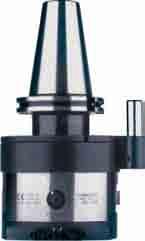
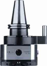
5 FOR HIGH PRECISION TECHNOOGY FOR HIGH PRECISION TECHNOOGY FOR HIGH PRECISION TECHNOOGY FOR HIGH PRECISION TECHNOOGY FOR HIGH PR The ISO 9 certification A D Andrea products Balanceable tool holders, up to G grade. Simple, adjustable radial mounted weights. TOPRUN arge CNC facing and boring heads for boring machines and machining centers. Designed as part of a new machine, new application. Performs turning, boring, back turning and more. Can be retrofit to most CNC s. U-TRONIC Modular tool holding system for boring, drilling, tapping, milling. Ultra rigid modular connection. MHD CNC facing and boring heads for machining centers. U-CENTER Facing heads with automatic feed. No electronic interface required. AUTORADIA Boring/facing/grooving heads. Designed for use on manual machines. Tool rotates while moving radially. SENSITIV T-TA

6 TECHNOOGY FOR HIGH PRECISION TECHNOOGY FOR HIGH PRECISION TECHNOOGY FOR HIGH PRECISION TECHNOOGY FOR HIGH PRECISION TECHNOOGY
7 FOR HIGH PRECISION TECHNOOGY FOR HIGH PRECISION TECHNOOGY FOR HIGH PRECISION TECHNOOGY FOR HIGH PRECISION TECHNOOGY FOR HIGH P INFO 3 nd edition April 25 D ANDREA s.p.a. Via Garbagnate 7 22 ainate (MI) - Italia Tel Fax info@dandrea.com
8 TECHNOOGY FOR HIGH PRECISION TECHNOOGY FOR HIGH PRECISION TECHNOOGY FOR HIGH PRECISION TECHNOOGY FOR HIGH PRECISION TECHNOOGY
9 FOR HIGH PRECISION TECHNOOGY FOR HIGH PRECISION TECHNOOGY FOR HIGH PRECISION TECHNOOGY FOR HIGH PRECISION TECHNOOGY FOR HIGH PR THE COMPANY TOPRUN 2 MODUHARD ANDREA SENSITIV T-TA 44 contents AUTORADIA U-CENTER U-TRONIC 46 INSERTS 58 ACCESSORIES AND SPARE PARTS 78 TECHNICA DATA 84 26

10 TOPRUN High speed balanceable toolholders 2 HSK-A ER p. 4 FORCE p. 5 WD p. 6 WN p. 7 PFS p. 8 FITMI p. 9 CM p. 2 MS p. 2 TR5 p. 22 HSK-E ER p. 24 PFS p. 25 TR32 p. 26 DIN 6987-A p ER p. 28 FORCE p. 29 WD p. 3 WN p. 3 PFS p. 32 FITMI p. 33

11 TOPRUN High speed balanceable toolholders MAS 43 BT Index p ER p. 34 FORCE p. 35 WD p. 36 WN p. 37 PFS p. 38 FITMI p. 39 CAT p ER p. 4 FORCE p. 4 WD p. 42 PFS p. 43


.")


12 TOPRUN Balanceable toolholders - Balancing and Precision 2 High precision monobloc toolholders for machining centres, balanceable for high speed machining. QUAITY TOPRUN toolholders are manufactured and guaranteed by design, manufacturing and sales procedures according to the ISO 9 standard (certification no. 66/98). Arbors are manufactured within tolerance AT3 and the concentricity with the tool seat is lower than.3 mm. BAANCING For high speed machining with TOPRUN toolholders, the two counterweights in the graduated groove (patented) have to be positioned following the indications provided by the electronic balancing unit; a quick and easy balancing of the toolholder complete with tension rod and tool according to the ISO 94/ standards. For machining up to 8, RPM it is sufficient to position the counterweights at and at 8. ADVANTAGES The use of TOPRUN balanceable toolholders provides the following advantages: considerable extension of spindle bearings life; considerable extension of tool life; improved accuracy and surface finish; drastic reduction of vibrations and noise level of the machining centre.
.")

13 Balanceable toolholders - Balancing and Precision D ANDREA The purpose of a toolholder s balancing is to improve the masses distribution of its body in order to produce centrifugal forces within a prescribed limit, when spinning at a given spindle speed (RPM). The problem of toolholder balancing has become more evident with the diffusion of high speed machining: reduced life of the spindle bearings, short cutting tool life, vibrations and poor surface finish. The balancing operation has the aim to bring the original unbalance U within the maximum admissible level G. The manufacturers of high speed milling machines usually prescribe a balancing level G or G 2.5 for the toolholders to be used on their machines according to the ISO 94/ standard. From the value of the maximum admissible unbalance level G and the spindle RPM, the value e can be calculated, corresponding to the balancing defect (expressed in g mm/kg) or the toolholder runout (expressed in µm). The patented TOPRUN balancing system allows a quick, easy and accurate achievement of high balancing standards of the toolholder, within.5 g mm/kg, without any need to remove or add material. Specifically, the original unbalance U of the tool and toolholder is neutralized by the resulting centrifugal force C produced by the two balancing masses T and T2. The operator is guided by the balancing unit for the appropriate positioning of the two masses. The TOPRUN toolholders are essential for high speed machining and they will enhance machines and modern tool s performance, extending life and improving quality standards. 3 e = g.mm/kg C T T G 6 G ,3 G 2.5 6,3 4 2,5,6 G 4 2,5,6 G.4,63,63,4,4,25,25,6,6 U, , RPM x.3.3.5
14 TOPRUN Balanceable collet chucks holder d d d d2 d3 2 HSK-A ER - DIN 6499 fig. fig. 2 Supplied with coolant tube - without collets and clamping wrenches HSK-A REF. CODE TYPE d d2 d3 2 kg fig. HSK-A63 ER ER HSK-A63 ER HSK-A63 ER ER HSK-A63 ER HSK-A63 ER ER HSK-A8 ER ER HSK-A8 ER HSK-A8 ER ER HSK-A8 ER HSK-A8 ER ER HSK-A ER ER HSK-A ER HSK-A ER ER HSK-A ER HSK-A ER ER HSK-A ER N The ring-nuts of the Toprun spindles allow the use of the ER collets with a working range of.5 mm. p. 22 p. 22 p p. 87
15 High precision ultra-tight balanceable toolholder D ANDREA FORCE 2 d d2 g HSK-A Supplied with coolant tube - without clamping wrench HSK-A REF. CODE d d2 2 kg HSK-A63 FORCE HSK-A63 FORCE HSK-A FORCE KIT FORCE KIT K FORCE 2 consisting of: FORCE 2 RC 2.6 RC 2.8 RC 2. RC 2.2 RC 2.6 CHV 5 KIT K FORCE 32 consisting of: FORCE 32 RC 32.6 RC 32.8 RC 32. RC 32.2 RC 32.6 RC 32.2 RC CHV 75 HSK-A REF. CODE KIT K FORCE 2 HSK KIT K FORCE 32 HSK KIT K FORCE 32 HSK xD D UTRA-TIGHT TIGHTENING The FORCE ultra high tightening power is guaranteed by the reduced allowance. PRECISION The concentricity precision is always below 5 micron VCR 2-32 COOANT OUTET VCR 2-32 screw for coolant passage through the tool (see p. 22) on request. p. 87 p. 94 p. 22 p. 22
16 TOPRUN Balanceable Weldon toolholder d d d d2 2 HSK-A WD - DIN 835-B fig. Supplied with coolant tube HSK-A REF. CODE d H5 d2 kg fig. HSK-A63 WD HSK-A63 WD HSK-A63 WD HSK-A63 WD HSK-A63 WD HSK-A63 WD HSK-A63 WD HSK-A63 WD HSK-A8 WD HSK-A8 WD HSK-A8 WD HSK-A8 WD HSK-A8 WD HSK-A8 WD HSK-A WD HSK-A WD HSK-A WD HSK-A WD HSK-A WD HSK-A WD HSK-A WD fig. 2 p. 2 p. 23 p. 87
17 Balanceable Whistle Notch toolholder D ANDREA a d d2 a d d2 2 HSK-A WN - DIN 835-E fig. 2 2 Supplied with coolant tube HSK-A REF. CODE d H5 d2 a kg fig. HSK-A63 WN HSK-A63 WN HSK-A63 WN HSK-A8 WN HSK-A8 WN HSK-A8 WN HSK-A WN HSK-A WN HSK-A WN fig. 2 p. 87 p. 23 p. 2
18 TOPRUN Balanceable face mill holder HSK-A PFS d d d d2 2 fig. M d3 fig. 2 Supplied with coolant tube HSK-A REF. CODE d d2 d3 M kg fig. HSK-A63 PFS HSK-A63 PFS HSK-A63 PFS HSK-A63 PFS HSK-A8 PFS HSK-A8 PFS HSK-A8 PFS HSK-A8 PFS M HSK-A PFS HSK-A PFS HSK-A PFS HSK-A PFS M p. 2 p. 24 p. 87
19 HSK-A FITMI Balanceable toolholder for milling heads with threaded fitting D ANDREA M d d2 d3 2 9 Supplied with coolant tube HSK-A REF. CODE M d H6 d2 d3 2 kg HSK-A63 FM HSK-A63 FM M HSK-A63 FM HSK-A63 FM HSK-A63 FM M HSK-A63 FM HSK-A63 FM HSK-A63 FM HSK-A63 FM M HSK-A63 FM HSK-A63 FM HSK-A63 FM HSK-A63 FM HSK-A63 FM M HSK-A63 FM HSK-A63 FM HSK-A FM HSK-A FM M HSK-A FM HSK-A FM HSK-A FM HSK-A FM M HSK-A FM HSK-A FM p. 87 p. 2
20 TOPRUN Morse taper toolholder HSK-A CM d d2 2 HSK-A REF. CODE MORSE d d2 kg HSK-A63 CM2. B HSK-A63 CM3.3 B HSK-A63 CM4.55 B HSK-A8 CM2. B HSK-A8 CM3.3 B HSK-A8 CM4.55 B HSK-A CM2.2 B HSK-A CM3.4 B HSK-A CM4.6 B p. 2
21 HSK-A MS Tapping toolholder D ANDREA a a d d2 2 HSK-A REF. CODE d d2 a kg 63 HSK-A63 MS M HSK-A63 MS 2 M HSK-A8 MS M HSK-A8 MS 2 M HSK-A8 MS 3 M HSK-A MS M HSK-A MS 2 M HSK-A MS 3 M p p. 2
22 TOPRUN Balanceable micrometric boring head Testarossa HSK-A TR5 2µm TR5 HSK-A63 Ø 2.5 ~ 22 RPM MAX ø ø 6 H6 ø Supplied with coolant tube HSK-A REF. CODE Ø kg 63 TR5 HSK-A ~ HSK-A REF. CODE Ø lb 63 TR5 HSK-A63 INCH ~ METRIC INCH D B... ø 8 g5 ø 96 Carbide tools REF. CODE Ø 2 B ~ B ~ p. 2 p. 29 p. 24 p. 95 p. 87 INFO
23 D ANDREA 22 B3... REF. CODE Ø B ~ TS 2 WCGT B ~ TS 2 TORX T6 B ~ B ~ B ~ B ~ TPGX 92.. CS 25 T TORX T8 B ~ B ~ B ~ B5... ø6 g5 ø ø6 g5 ø 93 Tools 93 Vibration-damping tools REF. CODE Ø B ~ 8 36 TS 2 WCGT TORX T6 B ~ 48 TS 2 B ~ 2 6 B ~ TPGX 92.. CS 25 T TORX T8 B ~ 6 84 B ~ B8... ø6 g5 ø 93 Tools with carbide shank REF. CODE Ø B ~ 8 45 TS 2 WCGT TORX T6 B ~ 6 TS 2 B ~ 2 75 B ~ TPGX 92.. CS 25 T TORX T8 B ~ 6 5 B ~ 8 2 p. 8-8 p. 29 INFO
24 TOPRUN Balanceable collet chucks holder HSK-E ER - DIN fig. 2 2 d d2 d d d2 Supplied without collets and clamping wrenches HSK-E REF. CODE TYPE d d2 d3 2 kg fig. HSK-E4 ER ER HSK-E4 ER HSK-E4 ER ER HSK-E5 ER ER HSK-E5 ER HSK-E5 ER ER fig. 2 N The ring-nuts of the Toprun spindles allow the use of the ER collets with a working range of.5 mm. p. 2 p. 22 p. 88-9
25 HSK-E PFS Balanceable face mill holder D ANDREA d d2 25 HSK-E REF. CODE d d2 kg 4 HSK-E4 PFS HSK-E4 PFS HSK-E5 PFS HSK-E5 PFS p. 24 p. 2
26 TOPRUN Balanceable micrometric boring head Testarossa HSK-E.. TR32 2µm TR32 HSK-E.. Ø 2.5 ~ 8 RPM MAX ø Ø 8 H6 ø METRIC HSK-E REF. CODE Ø 2 kg 4 TR32 HSK-E ~ TR32 HSK-E ~ INCH HSK-E REF. CODE Ø 2 lb 4 TR32 HSK-E4 INCH ~ TR32 HSK-E5 INCH ~ p. 2 p. 29 p. 24 INFO
27 D ANDREA B... 2 Ø 8 g5 Ø 96 Carbide tools REF. CODE Ø 2 B ~ B ~ B... Ø 8 g5 Ø 95 Tools REF. CODE Ø B ~ TS 2 WCGT TORX T6 B ~ 28 - TS 2 B ~ TPGX 92.. CS 25 T TORX T8 B... 4 Ø 8 g5 Ø 93 Tools REF. CODE Ø B ~ 4 42 B ~ 6 48 TPGX 92.. CS 25 T TORX T8 B ~ 8 54 p. 8-8 p. 29 INFO
28 TOPRUN Balanceable collet chucks holder DIN 6987-A ER - DIN d d fig d d2 d3 2 fig. 2 Supplied without collets and clamping wrenches ISO REF. CODE TYPE d d2 d3 2 kg fig. DIN6987-A4 ER ER 6.5 ~ 24 DIN6987-A4 ER DIN6987-A4 ER ER 25 ~ 6 38 DIN6987-A4 ER DIN6987-A4 ER ER 32 2 ~ DIN6987-A5 ER ER 25 ~ 6 38 DIN6987-A5 ER DIN6987-A5 ER ER 32 2 ~ 2 5 DIN6987-A5 ER DIN6987-A5 ER ER 4 3 ~ N The ring-nuts of the Toprun spindles allow the use of the ER collets with a working range of.5 mm. p. 22 p. 22 p p. 86

29 DIN 6987-A High precision ultra-tight balanceable toolholder D ANDREA FORCE d d2 g Without clamping wrench ISO REF. CODE d d2 2 kg 4 DIN6987-A4 FORCE DIN6987-A4 FORCE DIN6987-A5 FORCE DIN6987-A5 FORCE KIT FORCE KIT K FORCE 2 consisting of: FORCE 2 RC 2.6 RC 2.8 RC 2. RC 2.2 RC 2.6 CHV 5 KIT K FORCE 32 consisting of: FORCE 32 RC 32.6 RC 32.8 RC 32. RC 32.2 RC 32.6 RC 32.2 RC CHV 75 ISO REF. CODE 4 KIT K FORCE2 DIN KIT K FORCE32 DIN KIT K FORCE2 DIN KIT K FORCE32 DIN xD D UTRA-TIGHT TIGHTENING The FORCE ultra high tightening power is guaranteed by the reduced allowance. PRECISION The concentricity precision is always below 5 micron VCR 2-32 COOANT OUTET VCR 2-32 screw for coolant passage through the tool (see p. 22) on request. p. 86 p. 94 p. 22 p. 22
30 TOPRUN Balanceable Weldon toolholder DIN 6987-A WD - DIN 835-B d d2 2 2 fig. 3 d d fig. 2 ISO REF. CODE d H5 d2 kg fig. DIN6987-A4 WD DIN6987-A4 WD DIN6987-A4 WD DIN6987-A4 WD DIN6987-A4 WD DIN6987-A4 WD DIN6987-A4 WD DIN6987-A4 WD DIN6987-A5 WD DIN6987-A5 WD DIN6987-A5 WD DIN6987-A5 WD DIN6987-A5 WD DIN6987-A5 WD p. 22 p. 23 p. 86
31 DIN 6987-A WN - DIN 835-E Balanceable Whistle Notch toolholder D ANDREA a 2 fig. 3 a d d d d2 fig. 2 ISO REF. CODE d H5 d2 a kg fig. DIN6987-A4 WN DIN6987-A4 WN DIN6987-A4 WN DIN6987-A5 WN DIN6987-A5 WN DIN6987-A5 WN p. 86 p. 23 p. 22
32 TOPRUN Balanceable face mill holder DIN 6987-A PFS d d2 fig. M d d d2 fig. 2 ISO REF. CODE d d2 d3 M kg fig. DIN6987-A4 PFS DIN6987-A4 PFS DIN6987-A4 PFS DIN6987-A4 PFS DIN6987-A5 PFS DIN6987-A5 PFS DIN6987-A5 PFS DIN6987-A5 PFS M p. 22 p. 24 p. 86

33 DIN 6987-A FITMI Balanceable toolholder for milling heads with threaded fitting D ANDREA M d d2 d3 33 ISO REF. CODE M d H6 d2 d3 2 kg DIN6987-A4 FM DIN6987-A4 FM M DIN6987-A4 FM DIN6987-A4 FM DIN6987-A4 FM M DIN6987-A4 FM DIN6987-A4 FM DIN6987-A4 FM DIN6987-A4 FM M DIN6987-A4 FM DIN6987-A4 FM DIN6987-A4 FM DIN6987-A4 FM DIN6987-A4 FM M DIN6987-A4 FM DIN6987-A4 FM DIN6987-A5 FM DIN6987-A5 FM M DIN6987-A5 FM DIN6987-A5 FM DIN6987-A5 FM DIN6987-A5 FM M DIN6987-A5 FM DIN6987-A5 FM p. 86 p. 22
34 TOPRUN Balanceable collet chucks holder MAS 43 BT ER - DIN d d d d2 d3 fig. fig. 2 Supplied without collets and clamping wrenches ISO REF. CODE TYPE d d2 d3 2 kg fig. MAS43 BT3 ER ER 6.5 ~ 24 3 MAS43 BT3 ER MAS43 BT3 ER ER 25 ~ MAS43 BT4 ER ER 6.5 ~ 24 MAS43 BT4 ER MAS43 BT4 ER ER 25 ~ 6 38 MAS43 BT4 ER MAS43 BT4 ER ER 32 2 ~ MAS43 BT5 ER ER 25 ~ 6 38 MAS43 BT5 ER MAS43 BT5 ER ER 32 2 ~ 2 5 MAS43 BT5 ER MAS43 BT5 ER ER 4 3 ~ N The ring-nuts of the Toprun spindles allow the use of the ER collets with a working range of.5 mm. p. 23 p. 22 p p. 86
35 g MAS 43 BT High precision ultra-tight balanceable toolholder D ANDREA FORCE d d2 2 2 Supplied without clamping wrenches ISO REF. CODE d d2 2 kg 4 MAS43 BT4 FORCE MAS43 BT4 FORCE MAS43 BT5 FORCE MAS43 BT5 FORCE KIT FORCE KIT K FORCE 2 consisting of: FORCE 2 RC 2.6 RC 2.8 RC 2. RC 2.2 RC 2.6 CHV 5 KIT K FORCE 32 consisting of: FORCE 32 RC 32.6 RC 32.8 RC 32. RC 32.2 RC 32.6 RC 32.2 RC CHV 75 ISO REF. CODE 4 KIT K FORCE2 BT KIT K FORCE32 BT KIT K FORCE2 BT KIT K FORCE32 BT UTRA-TIGHT TIGHTENING COOANT OUTET The FORCE ultra high VCR 2-32 screw for coolant tightening power is passage through the tool 27(see guaranteed by the reduced p. 22) on request. allowance D 3xD PRECISION The concentricity precision is always below 5 micron. VCR 2-32 p. 86 p. 94 p. 22 p. 23
36 TOPRUN d d d d2 Balanceable Weldon toolholder MAS 43 BT WD - DIN 835-B fig. fig. 2 BT REF. CODE d H5 d2 kg fig. MAS43 BT4 WD MAS43 BT4 WD MAS43 BT4 WD MAS43 BT4 WD MAS43 BT4 WD MAS43 BT4 WD MAS43 BT4 WD MAS43 BT4 WD MAS43 BT5 WD MAS43 BT5 WD MAS43 BT5 WD MAS43 BT5 WD MAS43 BT5 WD MAS43 BT5 WD p. 23 p. 23 p. 86
37 MAS 43 BT WN - DIN 835-E Balanceable Whistle Notch toolholder D ANDREA a d d fig. 37 a d d fig. 2 BT REF. CODE d H5 d2 a kg fig. MAS43 BT4 WN MAS43 BT4 WN MAS43 BT4 WN MAS43 BT5 WN MAS43 BT5 WN MAS43 BT5 WN p. 86 p. 23 p. 23
38 TOPRUN Balanceable face mill holder MAS 43 BT PFS 38 M d d d d d2 fig. 2 fig. 2 BT REF. CODE d d2 d3 M kg fig. 3 MAS43 BT3 PFS MAS43 BT3 PFS MAS43 BT4 PFS MAS43 BT4 PFS MAS43 BT4 PFS MAS43 BT4 PFS MAS43 BT5 PFS MAS43 BT5 PFS MAS43 BT5 PFS MAS43 BT5 PFS M p. 23 p. 24 p. 86
39 MAS 43 BT FITMI Balanceable toolholder for milling heads with threaded fitting D ANDREA M d d2 d3 39 BT REF. CODE M d H6 d2 d3 2 kg MAS43 BT4 FM MAS43 BT4 FM M MAS43 BT4 FM MAS43 BT4 FM MAS43 BT4 FM M MAS43 BT4 FM MAS43 BT4 FM MAS43 BT4 FM MAS43 BT4 FM M MAS43 BT4 FM MAS43 BT4 FM MAS43 BT4 FM MAS43 BT4 FM MAS43 BT4 FM M MAS43 BT4 FM MAS43 BT4 FM MAS43 BT5 FM MAS43 BT5 FM M MAS43 BT5 FM MAS43 BT5 FM MAS43 BT5 FM MAS43 BT5 FM M MAS43 BT5 FM MAS43 BT5 FM p. 86 p. 23
40 TOPRUN Balanceable collet chucks holder CAT INCH ER - DIN d d2 2 4 fig. 2 2 fig d d2 d3 Supplied without collets and clamping wrenches CAT REF. CODE TYPE d d2 d3 2 kg fig. CAT4 UNC ER ER6 /64-3/8 24 CAT4 UNC ER CAT4 UNC ER ER25 /32-5/8 38 CAT4 UNC ER CAT4 UNC ER ER32 5/64-3/ CAT5 UNC ER ER32 5/64-3/4 5 CAT5 UNC ER CAT5 UNC ER ER4 /8-63 CAT5 UNC ER N The ring-nuts of the Toprun spindles allow the use of the ER collets with a working range of.5 mm. p. 24 p. 22
41 CAT INCH High precision ultra-tight balanceable toolholder D ANDREA FORCE d d2 g Without clamping wrench CAT REF. CODE d d2 2 lb CAT4 UNC FORCE 3/ CAT4 UNC FORCE -/ CAT5 UNC FORCE -/ KIT FORCE KIT K FORCE 3/4 consisting of: FORCE 3/4 RC 3/4./4 RC 3/4.5/6 RC 3/4.3/8 RC 3/4./2 RC 3/4.5/8 CHV 5 KIT K FORCE -/4 consisting of: FORCE -/4 RC -/4.3/8 RC -/4./2 RC -/4.5/8 RC -/4.3/4 RC -/4. CHV 75 CAT REF. CODE KIT K FORCE 3/4 CAT KIT K FORCE -/4 CAT KIT K FORCE -/4 CAT D UTRA-TIGHT TIGHTENING The FORCE ultra high tightening power is guaranteed by the reduced allowance. 33 COOANT OUTET VCR 3/4, - VCR -/4 screw for coolant passage through the tool (see p. 22) on request. 3xD PRECISION The concentricity precision is always below 5 micron. 2 VCR 3/4 VCR -/4 p. 94 p. 22 p. 24
42 TOPRUN Balanceable Weldon toolholder CAT INCH WD d d2 42 fig d d2 fig. 2 CAT REF. CODE d d2 lb fig. CAT4 UNC WD 3/ CAT4 UNC WD / CAT4 UNC WD 5/ CAT4 UNC WD 3/ CAT4 UNC WD CAT4 UNC WD -/ CAT5 UNC WD 3/ CAT5 UNC WD CAT5 UNC WD -/ p. 24 p. 23
43 CAT INCH PFS Balanceable face mill holder D ANDREA d d2 43 CAT REF. CODE d d2 lb CAT4 UNC PFS 3/ CAT4 UNC PFS CAT4 UNC PFS -/ CAT5 UNC PFS 3/ CAT5 UNC PFS CAT5 UNC PFS -/ CAT5 UNC PFS -/ p. 24 p. 24

44 MODUHARD ANDREA High precision modular toolholder system ARBORS EXTENSIONS REDUCTIONS AND COOANT FEED CHUCKING TOOS p p. 62 p. 7 p. 88 p. 86 p p. 63 p. 7 p. 64 p. 8-9 p. 86 p p. 65 p. 2 p. 86 p p g.6 2 g.6 2 p. 65 p. 2 p. 22 p p. 24 p. 23 p p. 25 p. 23
45 2 DA' NDREA MA DE IN I TA Y BF 5/ DA' NDREA MA DE IN I TA Y BF 5/ R E N DA' MA DE 32 HS N 5 Y I N I T A DA' NDREA MA DE IN I TA Y BF 5/ Index MODUHARD ANDREA High precision modular toolholder system HEADS AND DOUBE-BIT BORING BARS TESTAROSSA AND BORING BARS KIT p ø.2 D'AN DR EA MADE IN ITAY TRM HS p. 82 D'AN DR EA MADE I ITAY TRM p. 83 p. 96 p. 7 p. 83 p. 98 p. 86 p. 87 p. p D A TRM p. 88 p. 2 p. 4 p p p. 8-9 p p. 79 p p. 93 p. 8-8 p. INFO p WinTool p. 8-8 p. 2-5 p. 28


46 MODUHARD ANDREA What is MHD? 46 A modular toolholder system for boring, milling, drilling, tapping. A rigid high precision system, conceived and manufactured with the most advanced design and production facilities, backed by an experience over many decades in boring operations. A system of extreme flexibility and simplicity suitable for machine tools, machining centres and flexible manufacturing systems. A system for machining to closest tolerances with a high degree of surface finish. A system with a patented cylindrical-conical coupling and radial expanding pin ensuring maximum rigidity and concentricity in boring and milling jobs. A system with internal coolant supply in all its components. A system available in 8 sizes with full interchangeability of all components.

47 The MHD coupling D ANDREA SIZES AND DRIVING TORQUE MHD Ø d Ø m S Nm MHD 6 6 2,5 2-2,5 MHD ,5 MHD ,5-7,5 MHD MHD MHD MHD MHD Ø d Ø m S The MHD coupling is the heart of the tool system as it ensures utmost rigidity and concentricity during milling and boring operations. This is achieved by the cylindrical-conical fit and by a radial expanding bolt for clamping and driving. FITTING INSTRUCTIONS The conical and cylindrical surfaces should be carefully cleaned before assembly. This will ensure good rigidity and coaxiality and prevent any damage to the surfaces. Assembly -Secure the arbor to a rigid support. -Fit the required component (adaptor, extension, double-bit boring bar, boring head etc.) to the arbor ensuring that the radial expanding pin does not project from the cylindrical part. -Clamp the component by turning the radial pin clockwise with the hexagonal wrench provided or with a torque wrench. Recommended torque: MHD 6 = 2 2,5 Nm MHD 2 = 4 4,5 Nm MHD 25 = 6,5 7,5 Nm MHD 32 = 7 8 Nm MHD 4 = 6 8 Nm MHD 5 = 3 35 Nm MHD 63 = 8 9 Nm MHD 8 = 8 9 Nm Disassembly -Secure the arbor to a rigid support. -Unlock the radial pin by turning it counterclockwise. The above operations should be carried out using suitable tools. MAINTENANCE The conical and cylindrical surfaces of each component should be cleaned and lubricated at periodic intervals. The expanding radial pin should be treated regularly with an anti-souff lubricant. The slide guideway of the micrometric boring bars should be cleaned and lubricated at periodic intervals. The assembly tools should be maintained in perfect condition.

48 MODUHARD ANDREA Arbors Extensions Reductions ARBORS Arbors are manufactured in accordance with DIN 6987 A-B, MAS 43 BT, DIN 28, ANSI-CAT, DIN A and are made of carburized steel, hardened and ground to AT3 tolerance. They are available in three sizes, MHD 5, MHD 63 and MHD 8. Taper ISO 4 is recommended for size MHD 5 only. Arbor size MHD 8 is recommended for heavy milling and for bores deeper than 25 mm and exceeding 25 mm diameter. Special arbors are available on request. EXTENSIONS Extensions of various lengths are available for each MHD size, allowing greater flexibility in machining depth. REDUCTIONS MHD components of a smaller size can be used by means of adaptor sleeves which allow greater interchangeability and ensure tool rigidity. 48

49 DIN HSK-A Arbors D ANDREA ) MHD' d ) Cutting edge position Supplied with coolant tube HSK-A REF. CODE MHD d kg 5 HSK-A5 MHD HSK-A63 MHD HSK-A63 MHD HSK-A8 MHD HSK-A8 MHD HSK-A8 MHD HSK-A MHD HSK-A MHD HSK-A MHD ) MHD'd ) Cutting edge position Supplied with coolant tube HSK-A REF. CODE MHD d kg 63 HSK-A63 MHD HSK-A MHD HSK-A MHD HSK-A MHD p. 87 p. 2

50 MODUHARD ANDREA Arbors ISO 7388/ DIN 6987 ) AD MHD d 5 ) Cutting edge position ISO REF. CODE MHD d kg 3 DIN6987-A3 MHD DIN6987-A3 MHD DIN6987-A4 MHD DIN6987-A4 MHD DIN6987-A45 MHD DIN6987-A45 MHD DIN6987-A45 MHD DIN6987-A5 MHD DIN6987-A5 MHD DIN6987-A5 MHD AD+B ) 2 MHD' d ) Cutting edge position ISO REF. CODE MHD d kg 4 DIN6987-AD+B4 MHD DIN6987-AD+B5 MHD DIN6987-AD+B5 MHD DIN6987-AD+B5 MHD p. 22 p. 86
51 ISO 7388/ DIN 6987 Arbors D ANDREA ) B 2 MHD' d ) Cutting edge position ISO REF. CODE MHD d kg 4 DIN6987-B4 MHD DIN6987-B4 MHD DIN6987-B45 MHD DIN6987-B45 MHD DIN6987-B45 MHD DIN6987-B5 MHD DIN6987-B5 MHD DIN6987-B5 MHD p. 86 p. 22
52 MODUHARD ANDREA Arbors MAS 43 BT ) 52 ) Cutting edge position ISO REF. CODE MHD d kg 3 MAS43-BT3 MHD MAS43-BT3 MHD MAS43-BT35 MHD MAS43-BT4 MHD MAS43-BT4 MHD MAS43-BT45 MHD MAS43-BT45 MHD MAS43-BT45 MHD MAS43-BT5 MHD MAS43-BT5 MHD MAS43-BT5 MHD B 2 MHD' d MHD' d ) ) Cutting edge position ISO REF. CODE MHD d kg 4 MAS43-BT4B MHD MAS43-BT5B MHD MAS43-BT5B MHD MAS43-BT5B MHD p. 23 p. 86
53 MAS 43 BT Arbors D ANDREA B ) 2 MHD' d 53 ) Cutting edge position ISO REF. CODE MHD d kg 4 MAS43-BT4B MHD MAS43-BT4B MHD MAS43-BT5B MHD MAS43-BT5B MHD MAS43-BT5B MHD p. 86 p. 23
54 MODUHARD ANDREA Arbors ANSI/CAT ) ANSI/CAT METRIC M MHD' d 54 ) Cutting edge position ISO REF. CODE MHD d M lb 4 ANSI/CAT4 MHD M6 ANSI/CAT4 MHD ANSI/CAT45 MHD ANSI/CAT45 MHD M ANSI/CAT45 MHD ANSI/CAT5 MHD ANSI/CAT5 MHD M ANSI/CAT5 MHD p. 24
55 ANSI/CAT Arbors D ANDREA CAT INCH ) M MHD' d ) Cutting edge position ISO REF. CODE MHD d M lb 4 CAT4UNC MHD UNC 5/8 - CAT4UNC MHD CAT45UNC MHD CAT45UNC MHD UNC 3/ CAT45UNC MHD CAT5UNC MHD CAT5UNC MHD UNC CAT5UNC MHD CAT INCH ) M MHD'd ) Cutting edge position ISO REF. CODE MHD d M lb 4 CAT4UNC MHD UNC 5/ CAT5UNC MHD CAT5UNC MHD UNC CAT5UNC MHD p. 24
56 MODUHARD ANDREA Arbors DIN 28-A OTT ) M MHD' d 56 ) Cutting edge position ISO REF. CODE MHD d M kg 3 DIN28-A3 MHD M2.6 4 DIN28-A4 MHD M6 DIN28-A4 MHD DIN28-A45 MHD DIN28-A45 MHD M2.9 DIN28-A45 MHD DIN28-A5 MHD DIN28-A5 MHD M DIN28-A5 MHD NMTB ) M MHD' d ) Cutting edge position ISO REF. CODE MHD d M kg 4 NMTB4 MHD UNC 5/8 - NMTB4 MHD NMTB5 MHD NMTB5 MHD UNC NMTB5 MHD p. 25
57 Arbors D ANDREA DIN 228/A 227 M MHD' d MORSE REF. CODE MHD d M kg 4 MORSE4-A MHD M SIP MORSE4-A SIP MHD M4 57 DIN 228/B 86 MHD' d MORSE REF. CODE MHD d kg 4 MORSE4-B MHD MORSE5-B MHD p. 26
58 MODUHARD ANDREA Arbors R8 METRIC/INCH ) 58 ) Cutting edge position REF. CODE MHD d M kg R 8 (M2) M2x.75.8 R 8 (UNF 7/6-2) UNF 7/6-2.8 BR d2 h6 d2 h5 MHD' d fig. MHD' d M MHD d fig. 2 METRIC REF. CODE MHD d d2 fig. kg BR 6/ BR 2/ BR 25/ BR 32/ INCH REF. CODE MHD d d2 fig. lb BR BR -/ p. 27

59 Arbors D ANDREA DIN M d5 d4 d3 MHD' d d2 59 REF. CODE MHD d d2 d3 d4 d5 2 M kg DIN M2.8 DIN M2 2 DIN M6 5.4 DIN M6 5.3 MR M d4 d MHD' d d2 REF. CODE MHD d d2 d3 d4 M kg MR 5/ M6.5 MR 63/ M8 3. MR 8/ M 6.
60 MODUHARD ANDREA Carbide bars 6 CARBIDE BARS FOR DEEP-HOE MACHINING D Andrea solves the deep- diameter 6, 2, 25, 32 mm the machining of holes, TS double-bit roughing heads, hole boring machining by and ending with MHD arbor. whose depth is 6.3, 8 and TRM Testarossa finishing means of a wide programme BMD bars are built in three times the diameter/bar. heads and PE chucking tools of BMD carbide bars having different working lengths for BMD bars accept: for ER collets.
61 Carbide bars D ANDREA BMD Ød2h5 MHD' d METRIC REF. CODE MHD d d2 kg BMD 6/ BMD 6/ BMD 6/ BMD 2/ BMD 2/ BMD 2/ BMD 25/ BMD 25/ BMD 25/ BMD 32/ BMD 32/ BMD 32/ INCH REF. CODE MHD d d2 lb BMD 5/ BMD 5/ BMD 5/ BMD 3/ BMD 3/ BMD 3/ BMD BMD BMD BMD -/ BMD -/ BMD -/
62 MODUHARD ANDREA Extensions PR MHD' d 62 REF. CODE MHD d lb PR PR PR PR PR PR PR PR PR PR PR PR PR PR PR PR PR p. 96

63 RD Reductions D ANDREA MHD' d MHD' d2 REF. CODE MHD d MHD d2 lb RD 2/ RD 25/ RD 25/ RD 32/ RD 32/ RD 32/ RD 4/ RD 4/ RD 4/ RD 4/ RD 5/ RD 5/ RD 5/ RD 5/ RD 5/ RD 63/ RD 8/ RD 8/ p. 96
64 MODUHARD ANDREA Reductions RD MHD' d MHD' d2 64 REF. CODE MHD d MHD d2 lb RD 5/ RD 5/ RD 5/ RD 5/ RD 5/ RD 5/ RD 5/ RD 5/ RD 5/ RD 5/ p. 96
65 RAV Vibration-damping reductions D ANDREA MHD' d d3 MHD' d2 REF. CODE MHD d MHD d2 d3 lb RAV 5/ RAV 5/ RAV 5/ RAV 5/ RAV 5/ RAV 63/ RAV 8/ MHD'd MHD'd2 REF. CODE MHD d MHD d2 lb RD 5/ p. 96

66 MODUHARD ANDREA Balancing rings BC di de 3 6 g.6 2 A 66 REF. CODE MHD de di (G6) BC BC BC BC ASSEMBY -Remove the plastic guard ring -Insert the BC ring and lock the A screws.

67 4 2 3 M A D E BF Ø Ø Y Balancing rings D ANDREA g.6 2 g.6 2 g.6 2 g g.6 2 g.6 2 D 'A N D R E A I N I T A 25/ The BC balancing ring, only by setting the two incorporated graduated counterweights, allows to balance, in an accurate and economical way, the toolholder on which it is mounted. The use of the BC ring provides the following advantages: improved accuracy and surface finish considerable extension of tool life considerable extension of spindle bearings life drastic reduction of vibrations and noise level in the machining centre. The purpose of the balancing of a toolholder is to improve the distribution of the masses of the different elements in order to produce centrifugal forces within a prescribed limit, when spinning at a given spindle speed (RPM). The balancing operation for a toolholder has the aim to bring the original unbalance within the maximum admissible level G prescribed by the ISO 94/ standards.


68 MODUHARD ANDREA Heads and double-bit boring bars FEATURES The double-bit boring bars are simple and extremely stable due to serrated mating surfaces between the bit holder and the boring bar itself and also to the constant spacing between the bit holder clamp screw and the cutting edge. COMPONENTS. Setting screw 2. Tools clamp screws 3. Coolant outlets 4. Body 5. Bit holders

69 Heads and double-bit boring bars D ANDREA ø ø 2 ø SSCC SSCC SMC SSCC PT SSCC 69 A A A A ø fig. a fig. b fig. c USE The radial setting of the cutting edges should be carried out with tool presetting equipment. The boring bars are fitted with two bit holders for roughing operations involving heavy chip removal. The double-bit boring bars may include: - (fig. a) two SSCC bit holders on the same plane and with the two cutting edges set at identical radial distance for high feed rate roughing operations. - (fig. b) an SSCC bit holder and an SMCC bit holder not at the same plane and with the two cutting edges set at different radial distances for high cutting depth roughing operations. - (fig. c) The boring bars are fitted with a single bit holder for roughing and finishing operations involving normal chip removal. The serrated surface protection plate PT should always be fitted. IMPORTANT NOTE Bit holders and inserts should be firmly fixed.
70 MODUHARD ANDREA Heads and double-bit boring bars TS Ø 8 ~ 2 d2 MHD' d ø ø ø SSCC SMCC SSSC SSTC REF. CODE Ø MHD d d2 S... lb 7 TS 6/ ~ S 6. TS 2/ ~ S 2.99 TS 25/ ~ S TS 32/ ~ S TS 4/ ~ S TS 5/ ~ S TS 5/ ~ S TS 63/ ~ S ~ 6 S 8 TS 8/ ~ 2 S 9 BS Ø 28 ~ 68 MHD' d d2 ø ø SSCC SMCC SSSC REF. CODE Ø MHD d d2 S lb BS 5/ ~ S BS 5/ ~ S BS 5/ ~ S BS 63/ ~ S 25 BS 63/ BS 63/ ~ S BS 63/ BS 63/ ~ S 4-4 BS 63/ p. 28 p. 8-8 p. 96 INFO
71 BPS Ø 2 ~ 5 Double-bit boring crossbars D ANDREA Ø 66.7 A MHD' 8 Ø 4 H7 Ø PF 8/4 n 4 M2 x 35 SSCC 9 SMCC 9 SSSC 9 SSTC 9 PF 8/4 excluded REF. CODE Ø A S 9 kg BPS ~ 3 98 SSCC BPS ~ SMCC 9 SSSC BPS ~ SSTC 9. p. 97 p. 28 INFO

72 MODUHARD ANDREA Double-bit boring crossbars Ø.6 A MHD'8 Ø 6H7 Ø /4 GAS PF 8/6 N 4 M6 x 5 SSCC 9 SMCC 9 SSSC 9 SSTC 9 REF. CODE Ø A S..9 kg BPS ~ SSCC BPS ~ SMCC 9 SSSC 9 9 BPS ~ SSTC 9.5 p. 28 p. 97 INFO
73 Back-facing machining D ANDREA SSQC roughing bit-holders perform roughing machining of holes back-facing. The bit-holders can be mounted on the TS double-bit roughing heads, on BS double-bit boring bars and on BPS bars, thus allowing a working range from 2 to 82 mm diameter. For back-facing machining use only one SSQC bit-holder. In order to protect from the chips the part of the TS and BS serration groove remaining exposed, it is advisable to use a PT protection plate (see p. 78). TS... d BS... d BPS... d d2 d2 d2 73 d d d d min = (d+d2+) : 2 REF. CODE REF. TS/BS/BPS d d2 SSQC TS 6/ SSQC TS 2/ TS 25/25 39 SSQC BS 5/ BS 63/ BS 63/ TS 32/32 5 SSQC BS 5/ BS 63/ BS 63/ TS 4/ SSQC BS 5/ BS 63/ BS 63/ SSQC TS 5/ SSQC TS 5/ TS 63/63.5 SSQC TS 8/ TS 8/ BPS BPS SSQC BPS BPS BPS BPS p. 97 p. 28 INFO
74 MODUHARD ANDREA Bit-holders for double-bit items SSCC A 9 B REF. CODE Ø A B 74 SSCC ~ SSCC ~ SSCC ~ CCMT 62.. TS 25 TORX T8 SSCC ~ SSCC ~ SSCC ~ CCMT 9T3.. TS 4 TORX T5 SSCC ~ SSCC ~ SSCC ~ CCMT 24.. TS 5 TORX T25 SSCC ~ SSCC ~ SMCC A 9 B REF. CODE Ø A B SMCC ~ SMCC ~ CCMT 62.. TS 25 TORX T8 SMCC ~ SMCC ~ CCMT 9T3.. TS 4 TORX T5 SMCC ~ SMCC ~ SMCC ~ CCMT 24.. TS 5 TORX T25 SMCC ~ SMCC ~ p. 28 p. 8-8 INFO
75 Bit-holders for double-bit items D ANDREA A 75 SSSC SSTC 75 REF. CODE Ø A B SSTC ~ SSTC ~ TCMT TS 5 TORX T25 SSTC ~ Bit-holders for back-facing machining 9 A B B REF. CODE Ø A B SSSC ~ SSSC ~ SSSC ~ SSSC ~ SSSC ~ SSSC ~ SCMT 9T3.. TS 4 TORX T5 SCMT 24.. TS 5 TORX T25 A 9 B SSQC C REF. CODE Ø A B C SSQC ~ SSQC ~ CCMT 62.. TS 25 TORX T8 SSQC ~ SSQC ~ CCMT 9T3.. TS 4 TORX T5 SSQC ~ SSQC ~ SSQC ~ CCMT 24.. TS 5 TORX T25 SSQC ~ SSQC ~ p. 8-8 p. 28 INFO
76 MODUHARD ANDREA Toolholder heads and toolholders TP 76 REF. CODE Ø MHD d d2 PC.. lb ~ 5.52 PC.5 TP 8/ ~ 7.94 PC ~ 7.94 PC ~ 2.25 PC 3.5 TP 8/ ~ 6.42 PC ~ PC 5.5 TU 2 d2 MHD' d d2 MHD' d ø REF. CODE MHD d 2 d2 lb TU 5/ TU 63/ TU 8/ p. 96

77 Toolholder heads D ANDREA PC 5 B REF. CODE B lb PC PC PC PC PC CA ISO56 95 E 9 E 95 PTGN 6CA-6 PCN 6CA-2 B 45 F B F B F B F E E 75 PSSN 6CA-2 PSRN 6CA-2 On request REF. CODE F B E PTGN 6CA TNM PCN 6CA CNM PSSN 6CA SNM PSRN 6CA SNM. 24..
78 MODUHARD ANDREA Cover plates PT H d M 78 REF. CODE d H M PT M 3x2 PT M 4x4 PT M 4x6 PT M 5x2 PT M 6x25 PT M 8x25 PT M x3 PT M 2x35

79 Chamfering tools D ANDREA AS d2 d ø min ø max 79 REF. CODE Ø d d2 lb AS ~ AS ~ DCMT 72.. TS 25 TORX T8 AS ~ AS ~ AS ~ DCMT T3.. TS 4 TORX T5 AS ~ AS ~ DCMT 54.. TS 5 TORX T25 AS ~
80 MODUHARD ANDREA Testarossa and micrometric boring bars 2 m FEATURES High precision work to IT6 tolerance, with excellent surface finish, is achieved using TRM boring heads and micrometric boring bars. These are very sensitive and radial correction of micron can be effected directly on the machine and easily read on the vernier scale. COMPONENTS. Body 2. Slide toolholder 3. Expanding radial pin 4. Micrometric vernier scale 5. Slide clamp screw 6. Coolant outlet 7. Tool clamp screw 8. Oiler IMPORTANT NOTE - Tool and toolholder should be firmly fixed to the slide. The only screws to be used for the operations with heads and micrometric boring bars are those listed at point Components. - The screws not listed at the point Components should not be touched in order not to compromise the correct operation of boring bars and heads. - Bit holders and boring bars should be assembled with the insert turned on the same direction of the vernier scale (see photo).
. Fix the screw (5) at the end of the adjustment.")
.")
81 Testarossa and micrometric boring bars D ANDREA 8 - oosen the screw (5) before the vernier setting (4). Fix the screw (5) at the end of the adjustment. The POSITIVE micrometric adjustment should be carried out turning the the vernier counterclockwise (4). - Resume the radial clearance between vernier and slide toolholder every time the vernier s direction of rotation is inverted.
82 MODUHARD ANDREA Balanceable Testarossa METRIC mm REF. CODE Ø kg TRM32 HS ~ INCH REF. CODE Ø lb TRM32 HS INCH ~ MHD' B... TRM 32 HS Ø 2.5 ~ 2 Ø RPM MAX 2. Ø 8 H6 Ø B... Ø8 g5 Ø Carbide tools REF. CODE Ø 2 B ~ B ~ B... Ø 8 g5 Tools REF. CODE Ø B ~ TS 2 WCGT TORX T6 B ~ TS 2 B ~ TPGX 92.. CS 25 T TORX T8 4 B... Ø 8 g5 Ø 93 Tools REF. CODE Ø B ~ B ~ TPGX 92.. CS 25 T TORX T8 B ~ p. 29 p. 8-8 p INFO
83 Balanceable Testarossa D ANDREA mm TRM 5 HS Ø 2.5 ~ 22 RPM MAX 2. MHD' 5 Ø Ø6H6 Ø B METRIC INCH REF. CODE Ø kg TRM5 HS ~ REF. CODE Ø lb TRM5 HS INCH ~ TRM 5/5 Ø 2.5 ~ 3 (84) MHD 5 Ø Ø 6 H6 4 B... METRIC INCH REF. CODE Ø kg TRM5/ ~ 3 6 REF. CODE Ø lb TRM5/5 INCH ~ p. 95 p p. 29 INFO


84 MODUHARD ANDREA Tools B... D Ø 8 g5 Ø 96 Carbide tools REF. CODE Ø 2 B ~ B ~ B3... Ø6g5 Ø 93 Tools REF. CODE Ø B ~ TS 2 WCGT B ~ TS 2 TORX T6 B ~ B ~ B ~ B ~ TPGX 92.. CS 25 T TORX T8 B ~ B ~ B ~ p. 29 p. 8-8 p. 95 INFO
85 D ANDREA B Ø 6 g5 Ø 93 Vibration-damping tools REF. CODE Ø B ~ TS 2 WCGT TORX T6 B ~ TS 2 B ~ B ~ TPGX 92.. CS 25 T TORX T8 B ~ B ~ B Ø 6 g5 Ø 93 Tools with carbide shank REF. CODE Ø B ~ TS 2 WCGT TORX T6 B ~ TS 2 B ~ B ~ TPGX 92.. CS 25 T TORX T8 B ~ B ~ p. 8-8 p. 29 INFO
86 MODUHARD ANDREA Testarossa 2 mm TRM Ø 8 ~ 84 MHD' d Ø C SFTP SFCC METRIC 86 REF. CODE Ø MHD d C SF kg TRM 6/ ~ SF TRM 2/ ~ SF.. 2. TRM 25/ ~ SF TRM 32/ ~ SF TRM 4/ ~ SF TRM 5/ ~ SF.. 5 INCH REF. CODE Ø MHD d C SF lb TRM 6/6 INCH ~ SF TRM 2/2 INCH ~ SF TRM 25/25 INCH ~ SF TRM 32/32 INCH ~ SF TRM 4/4 INCH ~ SF TRM 5/5 INCH ~ SF p. 29 p. 8-8 p. 98 INFO
87 2 mm Micrometric boring bars D ANDREA Ø 28 ~ 63 MHD' d d2 Ø C SFTP SFCC METRIC REF. CODE Ø MHD d d2 C SF.. kg 87 BF 5/ ~ SF BF 5/ ~ SF BF 5/ ~ SF BF 63/ ~ SF..25 BF 63/ BF 63/ ~ SF..32 BF 63/ BF 63/ ~ SF..4 BF 63/ INCH REF. CODE Ø MHD d d2 C SF.. lb BF 5/25.63 INCH ~ SF BF 5/32.8 INCH ~ SF BF 5/4. INCH ~ SF BF 63/25. INCH ~ SF.. 25 BF 63/25.6 INCH BF 63/32.25 INCH ~ SF.. 32 BF 63/32.2 INCH BF 63/4.6 INCH ~ SF.. 4 BF 63/4.25 INCH p. 98 p. 8-8 p. 29 INFO
88 MODUHARD ANDREA Testarossa 2 mm TRM Ø 77 ~ 5 d2 MHD' d ø 5 SFTP 5 SFCC 5 88 PS... METRIC REF. CODE Ø MHD d d2 PS kg 77 ~ PS.3.7 TRM 5/ ~ 25 PS ~ PS.3 2 TRM 63/ ~ 25 PS ~ 4 PS TRM 5/ ~ 6 PS ~ 4 PS TRM 8/ ~ 6 PS ~ 2 PS ~ 3 PS TRM 8/ ~ 4 PS ~ 5 PS INCH REF. CODE Ø MHD d d2 PS lb 3. ~ 3.9 PS TRM 5/63 INCH ~ 4.9 PS ~ 5.9 PS TRM 63/63 INCH ~ 4.9 PS ~ 5.5 PS TRM 5/8 INCH ~ 6.3 PS ~ 5.5 PS TRM 8/8 INCH ~ 6.3 PS ~ 8.3 PS ~ 2.2 PS TRM 8/25 INCH ~ 6. PS ~ 9.7 PS p. 29 p. 98 INFO
89 Ø I 2 mm Double-bit crossbars for large diameters finishing D ANDREA BPS Ø 2 ~ OCK D'A N D M A D E N T R 2 R E A IT A Y SFCC 5 ø 66.7 SFTP 5 TR 2 A MHD' 8 Ø 4H7 PF 8/4 N 4 M2x CW 2 CW 2 REF. CODE Ø A SF..5 kg BPS ~ SFTP 5 BPS ~ SFCC 5 BPS ~ p. 98 p. 29 INFO

90 Ø MADE IN TR 2 IT A Y MODUHARD ANDREA Double-bit crossbars for large diameters finishing 2 mm BPS Ø 5 ~ SFCC 5 SFTP 5 TR 2 Ø CW 2 A MHD'8 Ø 6H7 OCK D'A ND R E A /4 GAS PF 8/6 N 4 M6 x 5 CW 2 PF 8/6 excluded REF. CODE Ø A SF..5 kg BPS ~ SFTP 5 BPS ~ SFCC 5 BPS ~ p. 29 p. 98 INFO
91 Testarossa for back-facing machining D ANDREA SFQC bit-holders perform back-facing applications. The bit-holders can be mounted on Testarossa micrometric heads, thus allowing a working range from 2 to 82 mm diameter. TRM - BF TRM... BPS... d d d d2 d2 d2 9 d d d d min = (d+d2+) : 2 REF. CODE REF. TRM/BF/BPS d d2 SFQC TRM 6/6 2 ~ SFQC TRM 2/ ~ TRM 25/ SFQC BF 5/ ~ 4 25 BF 63/ BF 63/ TRM 32/32 53 SFQC BF 5/ ~ BF 63/ BF 63/ TRM 4/4 68 SFQC BF 5/ ~ 65 4 BF 63/ BF 63/ TRM 5/5 56 ~ TRM 63 + PS.3 82 ~ TRM 8 + PS 2.3 ~ TRM 25 + PS.4 4 ~ SFQC BPS 2 + TR 2 22 ~ BPS 3 + TR 2 32 ~ BPS 4 + TR 2 42 ~ BPS 5 + TR 2 52 ~ BPS 6 + TR 2 62 ~ BPS 7 + TR 2 72 ~ p. 98 p. 29

92 MODUHARD ANDREA Micrometric head 2 mm TR 2 92 METRIC REF. CODE Ø kg TR ~ INCH REF. CODE Ø lb TR 2 INCH ~ CW CW 2 Ø SFCC 5 SFTP 5 3x56.5 REF. CODE lb CW E A PS B REF. CODE A B E lb PS PS PS PS PS PS PS p. 29 p. 8-8 p. 98 INFO
93 9 2 mm Bit-holders for double-bit items D ANDREA A SFTP B REF. CODE Ø A B SFTP ~ SFTP ~ SFTP ~ SFTP ~ TPGX 92.. CS 25T TORX T8 TPGX 3.. CS 389T TORX T8 A SFCC 93 9 B REF. CODE Ø A B SFCC ~ SFCC ~ SFCC ~ SFCC ~ SFCC ~ SFCC ~ CCGT 62.. TS 25 TORX T8 CCGT 9T3.. TS 4 TORX T5 Bit-holders for back-facing machining 9 A SFQC B C REF. CODE Ø A B C SFQC ~ SFQC ~ SFQC ~ SFQC ~ SFQC ~ SFQC ~ CCMT 62.. TS 25 TORX T8 CCMT 9T3.. TS 4 TORX T5 p. 8-8 p. 29 INFO


94 MODUHARD ANDREA Testarossa kit 94 KIT K TRM 5/63 KIT K TRM 63/63 KIT K TRM 5/8 KIT K TRM 8/8


95 Testarossa kit D ANDREA SUPPY TESTAROSSA boring heads are supplied in a robust metal box with a wide range of toolholders, tools, inserts and service wrenches. FEATURES High precision work to IT6 tolerance and with excellent surface finish is achieved using TRM boring heads. These are very sensitive and radial correction of micron can be effected directly on the machine and easily read on the vernier scale. FEXIBIITY The series of TRM heads permits high precision boring works from 6 to 5 mm diameter. 95 KIT K TRM 5/5

96 4 I T MODUHARD ANDREA Balanceable kit KIT K TRM 32 HS 2 mm Ø 2.5 ~ 2 RPM MAX consisting of: TRM 32 HS B.2 B.4 B.6 B.8 B. 5 TPGX 922 DC 2 WCGT 22 DC REF. CODE Ø K TRM32 HS ~ 2 K TRM32 HS INCH ~.47 TRM 32 HS COMPONENTS 6 2 B.2 B Ø 2 D'AN DR E A IN A MADE Y TRM 32 HS B.6 B.8 WCGT22 DC B. 2 TPGX922 DC
97 KIT Working range D ANDREA Ø B.2 B.4 Ø Ø Ø D 'A N DRE A MA D E IN ITA Y TRM 32 HS B.6 Ø 6-8 B.8 Ø 8- B. Ø -2 COMPONENTS. Body 2. Tool slide 3. Expanding pin 4. Micrometric vernier scale 5. Slide lock screw 6. Coolant outlet 7. Tool lock screw The boring head TRM 32 HS bores diameters from 2.5 to 2 mm. - Fit the tool B.. into seat and lock with screw (7). The cutting tool must be on the slide longitudinal axis.

98 MODUHARD ANDREA Balanceable kit KIT K TRM 5 HS 2 mm Ø 6 ~ 22 RPM MAX consisting of: TRM 5 HS B3.6 B3.8 B3. B3.2 B3.4 B3.6 B3.8 5 TPGX 922 DC 2 WCGT 22 DC REF. CODE Ø K TRM5 HS ~ 22 K TRM5 HS INCH ~.86 TRM 5 HS COMPONENTS B3.6 B Ø IN I TA Y D'A NDR E A DE HS 5 MA TRM WCGT22 DC TPGX922 DC B3. B3.2 B3.4 B3.6 B
99 KIT Working range D ANDREA ø Ø B3.6 B3.8 B3. ø 6-8 ø 8- ø -2 D' ANDREA MADE IN ITA Y TRM 5 HS B3.2 ø 2-4 B3.4 ø 4-6 B3.6 ø 6-8 B3.8 ø 8-22 COMPONENTS. Body 2. Tool slide 3. Expanding pin 4. Micrometric vernier scale 5. Slide lock screw 6. Coolant outlet 7. Tool lock screw 8. Oiler The boring head TRM 5 HS bores diameters from 6 to 22 mm. - Fit the tool B.. into seat and lock with screw (7). The cutting tool must be on the slide longitudinal axis.

100 MODUHARD ANDREA KIT K TRM 5/5 2 mm Ø 6 ~ 84 consisting of: TRM 5/5 B3.6 B3.8 B3. B3.6 B3.22 P25.63 SFTP25 SFTP32 SFTP5 BM 5 TPGX 922 DC TPGX 32 DC 2 WCGT 22 DC REF. CODE Ø KTRM5/ ~ 84 KTRM5/5 INCH ~ 3.3 TRM 5/5 COMPONENTS TPGX32 DC 2 SFTP5 6 8 BM P D'AN DREA MA D E IN IT A Y TRM 5/5 Ø Ø TPGX922 DC SFTP25 SFTP32 B3.6 B3.8 WCGT22 DC TPGX922 DC B3. B3.6 B3.22
101 I T Y KIT Working range D ANDREA Ø 6-3 Ø Ø Ø 5 B3.6 Ø 6-8 DAN ' DR E A M A D E IN IT A Y TRM 5/5 Ø Ø Ø Ø TRM 5/5 D A' N DR E A MA D E IN A Y 63 6 BM P25.63 SFTP 5 D'AN DR E A MA D E IN IT A TRM 5/5 Ø Ø 9 4 * B3.8 5 Ø 8-2 Ø * B3. Ø -7 SFTP 25 Ø * B3.6 Ø 6-23 SFTP 32 Ø * B3.22 Ø 22-3 COMPONENTS. Body 2.Tool slide 3.Expanding pin 4.Micrometric vernier scale 5. Slide lock screw 6.Coolant outlet 7. Tool lock screw 8.Oiler The boring head TRM 5/5 bores diameters from 6 to 84 mm. - For bores from Ø 6 to 3 mm fit the tool B.. into seat and lock with screw (7). The cutting tool must be on the slide longitudinal axis. - For bores from Ø 28 to 54 mm fit extension P25.63 into seat and lock with screw (7). - For bores from Ø 54 to 84 mm fit sleeve BM into seat. Before tightening the screw (7) make sure that the latter engages the recess provided in sleeve BM which shall not project from the tool slide; if so, fit the sleeve overturned into seat. Fit the bit holder SF.. and secure it by the appropriate screw. * For a best flexibility of the TRM 5/5 kit, the working range of the B3.8, B3., B3.6, B3.22 tools is different from those suggested and reported on page 82.

102 MODUHARD ANDREA KIT K TRM 5/63 - K TRM 63/63 2 consisting of: TRM../63 B3.6 B3.8 B3. B3.6 B3.22 P2.3 P2.3 P3.3 PS.3 SFTP25 SFTP32 SFTP5 5 TPGX 922 DC TPGX 32 DC 2 WCGT 22 DC 2 mm Ø 6 ~ 25 REF. CODE MHD Ø K TRM5/ ~ 25 K TRM63/ ~ 25 K TRM5/63 INCH ~ 4.92 K TRM63/63 INCH ~ 4.92 TRM 5/63-63/63 COMPONENTS TPGX32 DC SFTP5 2 9 PS.3 P2.3 P TPGX922 DC 9 SFTP25 SFTP32 P2.3 B3.6 B WCGT22 DC TPGX922 DC 7 B3. B3.6 B3.22
103 KIT Working range D ANDREA Ø 6-3 Ø 28-8 Ø Ø 63 P2.3 B3.6 *B3.8 Ø 6-8 Ø P2.3 P SFTP 5 PS.3 Ø *B3. Ø -7 *B3.6 Ø 6-23 SFTP 25 Ø 28-7 *B3.22 Ø 22-3 SFTP 32 Ø 36-8 COMPONENTS. Body 2. Tool slide 3. Expanding pin 4. Micrometric vernier scale 5. Slide lock screw 6. Coolant outlet 7. Tool lock screw 8. Oiler 9. Toolholder lock screws The boring head TRM 63 bores diameters from 6 to 25 mm. - For bores from Ø 6 to 3 mm fit the toolholder P2.3 at the centre of the slide and secure it by screws (9). Fit the tool B.. and secure it by screws (7). The cutting tool must be on the slide longitudinal axis. - For bores from Ø 28 to 8 mm fit the toolholder P.. in the slide and secure it by screws (9). - For bores from Ø 77 to 25 mm fit the toolholder PS.3 in the slide and secure it by screws (9). Fit the bit holder SF.. on the toolholder and secure it by the screw. * For a best flexibility of the TRM 5/63 and 63/63 kits, the working range of the B3.8, B3., B3.6, B3.22 tools is different from those suggested and reported on page 82.

104 MODUHARD ANDREA KIT K TRM 5/8 - K TRM 8/8 4 consisting of: TRM../8 B3.6 B3.8 B3. B3.6 B3.22 P2.3 P2.3 P3.3 P4.3 PS2.3 PS3.3 SFTP25 SFTP32 SFTP5 5 TPGX 922 DC TPGX 32 DC 2 WCGT 22 DC 2 mm Ø 6 ~ 22 REF. CODE MHD Ø K TRM5/ ~ 22 K TRM8/ ~ 22 K TRM5/8 INCH ~ 8.66 K TRM8/8 INCH ~ 8.66 TRM 5/8-8/8 COMPONENTS TPGX32 DC SFTP5 2 9 PS2.3 PS3.3 P2.3 P3.3 P TPGX922 DC 9 SFTP25 SFTP32 P B3.6 B3.8 WCGT22 DC TPGX922 DC 7 B3. B3.6 B3.22
105 KIT Working range D ANDREA Ø 6-3 Ø 3-96 Ø Ø 8 58 P2.3 B3.6 Ø 6-8 *B3.8 Ø P2.3 P PS... SFTP5 PS 2.3 Ø *B3. Ø P4.3 PS 3.3 Ø 4-22 *B3.6 Ø 6-23 SFTP 25 Ø 3-86 *B3.22 Ø 22-3 SFTP 32 Ø COMPONENTS. Body 2. Tool slide 3. Expanding pin 4. Micrometric vernier scale 5. Slide lock screw 6. Coolant outlet 7. Tool lock screw 8. Oiler 9. Toolholder lock screws The boring head TRM 8 bores diameters from 6 to 22 mm. - For bores from Ø 6 to 3 mm fit the toolholder P2.3 at the centre of the slide and secure it by screws (9). Fit the tool B.. and secure it by screws (7). The cutting tool must be on the slide longitudinal axis. - For bores from Ø 3 to 96 mm fit the toolholder in the slide and secure it by screws (9). - For bores from Ø 95 to 22 mm fit the toolholder PS.. in the slide and secure it by screws (9). Fit the bit holder SF.. on the toolholder and secure it by the screw. * For a best flexibility of the TRM 5/8 and 8/8 kits, the working range of the B3.8, B3., B3.6, B3.22 tools is different from those suggested and reported on page 82.

106 MODUHARD ANDREA Toolholders kit for TRM 8/25 KIT K3 (TRM 8/25) 2 mm Ø 36 ~ 4 6 consisting of: P2.4 P3.4 P4.4 PS.4 PS2.4 PS3.4 SFTP32 SFTP4 SFTP5 REF. CODE Ø K3 TRM8/ ~ 4 TRM 25 COMPONENTS 2 9 SFTP 5 PS.4 PS2.4 PS3.4 P2.4 P3.4 P SFTP32 SFTP4
107 KIT Working range D ANDREA Ø Ø 35-5 Ø 25 9 P2.4 8 PS SFTP 5 25 PS.4 ø 35-2 P3.4 2 PS2.4 ø 25-3 SFTP32 ø PS3.4 ø 35-4 P4.4 PS4.4 ø 45-5 SFTP 32 ø 4-23 SFTP 4 ø COMPONENTS. Body 2. Tool slide 3. Expanding pin 4. Micrometric vernier scale 5. Slide lock screw 6. Coolant outlet 7. Tool lock screw 8. Oiler 9. Toolholder lock screws The boring head TRM 25 bores diameters from 36 to 5 mm. - For bores from Ø 36 to 37 mm fit the toolholder P.. in the slide and secure it by screws (9). - For bores from Ø 35 to 5 mm fit the toolholder PS.. in the slide and secure it by screws (9). Fit the bit holder SF.. on the toolholder and secure it by the screw.

108 MODUHARD ANDREA Boring kit for mold makers KIT K BORE mm Ø 8 ~ 28 8 consisting of: RD 5/6.4 TRM 6/6 SFCC 6 TS 6/6 2 SSCC 6 RD 5/2.7 TRM 2/2 SFCC 2 TS 2/2 2 SSCC 2 CCGT 622 DC REF. CODE Ø K BORE ~ 28 WORKING RANGE ø 5 ø 5 ø ø 2 2 ø 8-22 ø 8-22 ø ø 22-28

109 KIT K BORE 28-5 Boring kit for mold makers D ANDREA 2 mm Ø 28 ~ 5 consisting of: RD 5/25.87 TRM 25/25 SFTP 25 TS 25/25 2 SSCC 25 RD 5/32.87 TRM 32/32 SFTP 32 TS 32/32 2 SSCC 32 TPGX 922 DC 9 REF. CODE Ø K BORE ~ 5 WORKING RANGE Ø 5 Ø 25 Ø 5 Ø Ø Ø Ø Ø


110 MODUHARD ANDREA BMD kit consisting of: BMD 6/6.4 BMD 6/6.7 TRM 6/6 BMD 2/2.7 BMD 2/2.2 TRM 2/2 SFCC 6 SFCC 2 K BMD mm Ø 8 ~ 28 REF. CODE Ø K BMD ~ 28 consisting of: BMD 25/25.6 BMD 25/25.25 BMD 25/ TRM 25/25 SFCC 25 K BMD mm Ø 28 ~ 38 REF. CODE Ø K BMD ~ 38 consisting of: BMD 32/32.95 BMD 32/32.25 BMD 32/32.35 TRM 32/32 SFTP 32 K BMD mm Ø 36 ~ 5 REF. CODE Ø K BMD ~ 5
111 BMD kit D ANDREA WORKING RANGE 25 6 K BMD 8-28 BMD 6/6.4 BMD 6/6.7 TRM 6/6 SFCC 6 Ø BMD 2/2.7 BMD 2/2.2 TRM 2/2 SFCC 2 Ø WORKING RANGE K BMD BMD 25/ Ø BMD 25/25.6 BMD 25/25.25 TRM 25/25 SFTP 25 WORKING RANGE K BMD BMD 32/32.95 BMD 32/32.25 BMD 32/32.35 TRM 32/32 SFTP 32 Ø 36-5

112 MODUHARD ANDREA Tools and toolholders for Testarossa kit E A PS B 2 REF. CODE A B E kg PS PS PS PS PS PS PS D E P.. B C A REF. CODE A B C D E kg P P P P P P p. 99
113 9 Tools and toolholders for Testarossa kit D ANDREA P Ø 6g6 Ø REF. CODE kg P SFTP A B REF. CODE A B SFTP SFTP SFTP SFTP TPGX 92.. CS 25T TORX T8 TPGX 3.. CS 389T TORX T8 p. 99 p. 8-8 p. 29 INFO
114 95 MODUHARD ANDREA Tools and toolholders for Testarossa kit Ø P Ø 3 Ø 6 H6 REF. CODE kg P D B... Carbide tools ø 8 g5 96 REF. CODE 2 B B B... Tools REF. CODE B TS 2 WCGT TORX T6 B TS 2 B TPGX 92.. CS 25 T TORX T8 4 Ø 8 g5 Ø Ø 8 g5 B Tools REF. CODE B B TPGX 92.. CS 25 T TORX T8 B p. 29 p. 8-8 p. 99 p. 95 INFO

115 D ANDREA 22 B3... Ø6g5 Ø 93 Tools REF. CODE B TS 2 WCGT B TS 2 TORX T6 B B B B TPGX 92.. CS 25 T TORX T8 B B B consisting of: B3.6 B3.8 B3. B3.6 B TPGX922 3 WCGT22 K 2.5 Ø 6 ~ 3 REF. CODE Ø K ~.8 p. 8-8 p. 29 INFO


116 MODUHARD ANDREA Chucking tools 6 CHUCKING TOOS Combi-toolholders Weldon (DIN 835 B) and Whistle Notch (DIN 835 E) with axial adjustment screw. Collet chucks to DIN 6499 sizes ER, ER 6, ER 2, ER 25, ER 32, ER 4, including axial adjustment screw. Supplied without collets. Tapping chuck holders for high production thread cutting. arge length compensation in response to tension and compression. With quick-change clutch for tap holders with or without torque clutch. Universal milling cutterholders for disc cutters and facing cutters. Toolholders with internal morse taper for tools with thread to DIN 228-A and tang to DIN 228-B. Drill chuck-holders with internal taper B6 to DIN 238. Semi-finished toolholders for special tools with hardened and ground MHD coupling part and cylindrical part with hardness HRC Coolant chucking tools.

117 Collets chucking tools D ANDREA 2 PE ER DIN 6499 Supplied without collets and clamping wrenches REF. CODE MHD d d lb N. m PE 6 / ERM ~ ER-M EM 3 PE 2 / ER6M ~ ER-6M E6M 4 PE 25 / ER2M ~ ER-2M E2M 8 PE 32 / ER25M ~ ER-25M E25M 6 PE 4 / ER ~ UM/ER25 E25 2 PE 5 / ER ~ UM/ER25 E PE 5 / ER ~ UM/ER32 E32 22 PE 63 / ER ~ UM/ER32 E PE 63 / ER ~ UM/ER4 E Collet chucks to DIN 6499 sizes ER, ER 6, ER 2, ER 25, ER 32, ER 4 supplied with axial adjustment screw and without collets. MHD FORCE 2 MHD' d d2 d3 MHD' d d METRIC Without clamping wrench REF. CODE MHD d d2 d3 kg FORCE 5/2 HS FORCE 63/32 HS INCH REF. CODE MHD d d2 d3 lb FORCE 5 3/4 HS FORCE 63 -/4 HS p p
118 MODUHARD ANDREA Weldon Whistle Notch chucking tools AW DIN 835 B-E 2 DIN 835-E W.-NOTCH MHD' d d2 d3 fig. 2 3 DIN 835-B WEDON DIN 835-E W.-NOTCH MHD' d d2 d3 fig. 2 DIN 835-B WEDON METRIC REF. CODE MHD d d2 H5 d3 2 3 fig. kg AW 5/ AW 5/ AW 5/ AW 5/ AW 5/ AW 5/ AW 5/ AW 5/ AW 63/ AW 63/ AW 63/ AW 63/ AW 8/ Combi-toolholders Weldon (DIN 835 B) and Whistle Notch (DIN 835 E) with axial adjustment screw. p. 96-2
119 AW INCH Weldon Whistle Notch chucking tools D ANDREA 2 W.-NOTCH MHD' d d2 d3 fig. 2 3 WEDON W.-NOTCH MHD' d d2 d3 fig. 2 WEDON INCH REF. CODE MHD d d2 H5 d3 2 3 fig. lb AW 5 / AW 5 3/ AW 5 / AW 5 5/ AW 5 3/ AW 63 / AW 63 5/ AW 63 3/ AW AW 63 -/ AW 8 -/ AW p. 96-2

120 MODUHARD ANDREA Disc and facing cutter holders PF MHD' d d2 d3 d4 fig. M 2 MHD' d d2 d3 d4 d5 fig. 2 METRIC REF. CODE MHD d d2 d3 d4 d5 M fig. kg PF 4/ M PF 5/ M PF 5/ M PF 5/ M PF 5/ M PF 63/ M PF 63/ M PF 8/ M PF 8/ M M PF 8/ M M INCH REF. CODE MHD d d2 d3 d4 fig. lb PF 5 3/ / PF / PF 63 3/ / PF / PF 63 -/ / PF 8 -/ / PF Combi-chucking tools for disc and facing cutter holders. p. 96-2

121 CM DIN 228 A-B Morse taper chucking tools D ANDREA MHD' d d2 DIN 228 B 2 2 F d3 3 DIN 228 A REF. CODE MHD d MORSE d2 d3 F lb CM 5/ M6.323 CM 5/ M.544 CM 5/ M CM 63/ M CM 63/ M6 4.4 MT DIN 228-A To chuck a morse taper tool with thread proceed as follows: a. Drive in screw. b. Remove expanding pin 2 and sleeve 3 to allow the Allen wrench to be introduced from the rear. c. Fit the tool and tighten screw clockwise. d. Reassemble expanding pin 2 and sleeve 3. MT DIN 228-B To chuck a morse taper tool with tang remove screw. Combi-chucking tools for morse taper with DIN 228-A thread bore and with DIN 228-B tooth. p. 96-2
122 MODUHARD ANDREA Tapping chuck holders AM a a MHD' d d2 d3 WFK 22 REF. CODE MHD d WFK Capacity d2 d3 a lb AM 5/M WFK 5B/A 38 M 3 ~ AM 5/M WFK 225B/A 38 M 8 ~ AM 63/M WFK 5B/A 38 M 3 ~ AM 63/M WFK 225B/A 38 M 8 ~ Tapping chuck holders suitable for high production. Great axial adjustment both in compression and tension. There is the possibility of using quick change clutches with or without torque clutch. p p

123 Drilling chuck holders and semifinished chuck holders D ANDREA 24 B6 DIN 238 MHD' d Ø B6 REF. CODE MHD d lb B 5/ B 63/ Drilling chuck holders with B6 DIN 238 thread. 23 NS MHD' d d2 HRC REF. CODE MHD d d2 lb NS NS NS Semifinished chucking holders for special tools, manufactured with the tempered and ground part of the MHD coupling and the cylindrical neutral part with a hardness of HRC p. 96

124 MODUHARD ANDREA Coolant chucking tools ACR/NC MHD' d MHD' d d2 R ø 8 24 REF. CODE MHD d R d2 2 RPM max BAR lb ACR/NC 5/ max 4.9 ACR/NC 5/ max 5.53 ACR/NC 63/ max.25 N Activate coolant prior to starting spindle to prevent damage to internal components. p. 96

125 Coolant chucking tools D ANDREA ACR R 3/8 MHD' d MHD' d d REF. CODE MHD d d2 RPM max BAR lb ACR 63/ max N Activate coolant prior to starting spindle to prevent damage to internal components. p. 96


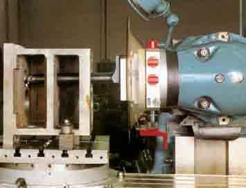
126 SENSITIV T-TA Boring and facing heads with manual and automatic feed

127 Index SENSITIV T-TA Boring and facing heads with manual and automatic feed GENERA FEATURES p. 28 COMPONENTS AND ASSEMBY p. 29 SUPPY p. 3 ARBORS p. 3 ACCESSORIES p TECHNICA DATA p. 36

128 SENSITIV T-TA General features The line of T-TA boring and facing heads is provided with radial feed movement of the radial slide while the head rotates. The radial feed can be either manually operated by a crank or automatic. Via an interchangeable taper, these heads can be utilized on milling machines, boring machines, jig boring machine, radial drills and will allow to perform a wide range of machining operations such as facing, back-facing, boring, taper boring, grooving both on ID or OD. The T-TA line of heads includes 4 models: T provided with manual radial feed only; TA 2, TA 7 and TA 22 provided with manual and automatic radial feed. A wide range of toolholders is available for these heads to allow the widest range of machining operations. 28
129 Components and assembly D ANDREA COMPONENTS. Stationary body 2. Rotating body 3. Interchangeable body 4. Feed crank 5. Quick return crank 6. Automatic feed crank 7. Automatic feed disengage button 8. Crank lock 9. Micrometric vernier scale. Centesimal vernier scale. Tool slide 2. Position stop 3. Toolholder clamp screw 4. Check rod 5. Transparent guard 6. Slide clamp screw 7. Toolholder check pins 8. Fork 29 ASSEMBY The SENSITIV are mounted on the machine via the taper. The check rod 4, inserted in fork 8 and locked onto the machine head, prevents the fixed body from rotating. For severe, heavy tooling, it is advisable to apply a flange to block the SENSITIV onto the sleeve or the head of the machine tool. The type of flange to be used depends on the machine model and on whether or not there are threaded holes in the front of the spindle or machine head. The flange may be easily built by the customer or supplied by D Andrea.
130 SENSITIV T-TA Supply INFO The standard K Kit includes the following in a case: T or TA head; transparent guard; 2 boring toolholders (P2, P3), 2 facing toolholders (P, P2), 3 heads (T, T2, T3), carbide tools; check rod; set of wrenches; instruction booklet; warranty card. Other accessories are also available upon request. Fitting tapers are optional. P2 T P3 P T2R P2 T3U SAFETY The T-TA are equipped with a transparent guard that ensures safe use. In addition, the toolholder slide is fitted with a safety device that prevents the toolholder from being released. 3 KIT K consisting of: T../TA.. P 2 P 3 P P 2 T T 2R T 3U Tools M2 T TA 2 TA 7 TA 22 REF. CODE CODE CODE CODE K KIT K3 consisting of: P 2 P 3 P P 2 T T 2R T 3U Tools M2 T - TA 2 TA 7 TA 22 REF. CODE CODE CODE K
131 Arbor D ANDREA REF. T - TA 2 TA 7 TA 22 CODE CODE CODE DIN 6987/CAT ISO ISO 7388 ISO MAS-BT ISO ISO DIN 28 OTT REF. T - TA 2 TA 7 TA 22 CODE CODE CODE ISO ISO 4 inch ISO ISO 5 inch CHUCKING TOO FOR MHD ARBORS MHD' d REF. T - TA 2 CODE MHD d MHD 5 T / TA REF. TA 7 CODE MHD d MHD 63 TA REF. TA 22 CODE MHD d MHD 8 TA

132 SENSITIV T-TA Accessories T and TA heads are designed for applying modular toolholders and interchangeable fitting tapers. All heads are made with dovetail guides on the slide for mounting the tool holders. This allows optimum positioning of the toolholders and ensures that they are very securely fastened in place. The toolholders have a tapered fitting for inserting the interchangeable heads available in right and left versions, screw-locking positive inserts and for round tools specifically made of carbide (M2). A BORING TOOHODERS P2 P3 P4 P5 B D ø min. 32 T - TA 2 TA 7 TA 22 REF. CODE A B D Ø min. P ,5 P , P ,5 P , P P P P P ,5 P P P FACING TOOHODERS A P P2 P3 D REF. CODE A Ø P T - TA 2 P P P TA 7 P P P TA 22 P P
133 Accessories D ANDREA HEADS T T2R T3U A ø 6 6 D REF. CODE D A Ø T T - TA 2 T2 R T3 U T TA 7 T2 R T3 U T TA 22 T2 R T3 U TOOS M2 33 A A2 A3 A4 A5 A6 B B2 B3 B ø T TA 2 TA 7 TA 22 REF. CODE Ø REF. CODE Ø REF. CODE Ø A 8 M A M A 2 M A2 8 M A2 M A2 2 M A3 8 M A3 M A3 2 M A4 8 M A4 M A4 2 M A5 8 M A5 M A5 2 M A6 8 M A6 M A6 2 M B 8 M B M B 2 M B2 8 M B2 M B2 2 M B3 8 M B3 M B3 2 M B4 8 M B4 M B4 2 M
134 SENSITIV T-TA Accessories D HEADS 9 T2 T22R A F REF. CODE D A F T - TA 2 TA 7 TA 22 T T22 R T T22 R T T22 R CCMT 9T CCMT 9T CCMT T23 T24R D HEADS 34 A 9 F REF. CODE D A F T - TA 2 TA 7 TA 22 T T24 R T T24 R T T24 R CCMT 9T CCMT 9T CCMT D HEADS T27 T28R 5 A 8 5 F REF. CODE D A F T - TA 2 TA 7 TA 22 T T28 R T T28 R T T28 R CCMT 9T CCMT 9T CCMT
135 Accessories D ANDREA D HEADS T25 T26R 45 A F REF. CODE D A F T - TA 2 TA 7 TA 22 T T26 R T T26 R T T26 R SCMT 9T SCMT 9T SCMT D HEADS T4 6 T4 9 T42 6R T42 9R A 35 F REF. CODE D A F T - TA 2 TA 7 TA 22 T T42.6 R T T42.6 R T T42.9 R T T42.6 R T T42.9 R X X X6 9T X X6 9T On right heads (R) left inserts () are used and vice versa p. 8-82
136 SENSITIV T-TA Technical data A H G B P2 P3 Ø F P P2 P3 P4 Ø I P D C E 36 TECHNICA DATA T TA 2 TA 7 TA 22 A mm inch B mm inch C mm inch M6 M6 M8 M2 D mm inch E mm inch F max P standard mm inch P 2 standard mm inch P 3 mm inch G mm inch H P2 standard mm inch P3 standard mm inch P4 mm inch P5 mm inch I max. mm inch Radial trasverse mm inch Feed mm/ inch/ Feed mm/ inch/ Rapid return mm/ inch/ Max. speed RPM RPM Net weight kg pound Torque Nm Ib ft Motor power Kw hp

137 D ANDREA 37

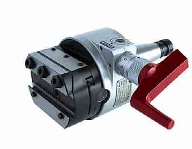
138 AUTORADIA Automatic facing heads


139 Index AUTORADIA Automatic facing heads AUTORADIA p. 4 COMPONENTS AND ASSEMBY p. 4 SUPPY p. 42 TOOHODERS-INTERCHANGEABE FEEDS p. 43 TECHNICA DATA p. 44

140 MADE IN ITAY AUTORADIA Autoradial 4 CW serial no. 988 RPM max 8 A A serial no. D ANDREA 988 MADE IN ITAY RPM max 8 AR R R D ANDREA AR START STOP CCW REVERSE Facing heads with automatic feed and quick return of the slide without stopping or reversing the spindle of the machine tool. Available in 3 models: AR, AR 25 and AR 6; they have got a feed and quick return. To change the feed, some interchangeable, optional, gear blocks (F) are available, for feeds in mm/rev. of:.5;.;.2;.4;.6 and a quick return of.8 mm/rev. The interchangeable arbor uses the same locking system used in the MHD modular system. A simple attachment of the toolholders to the slide favours the manufacturing of special toolholders. The AUTORADIA heads are applicable on machining centres and on N.C. machines and, without the need of any electronic interface, they can execute automatically a working cycle of: Facing Backfacing Internal or external grooving for spring washers and O-rings Record spiral cutting on flanges. The cycle is composed of the working feed and of the quick return of the slide without ever stopping or reversing the rotation of the spindle. To reset the cycle, merely reverse the spindle rotation for a few revolutions.


141 MA D E IN IT A Y MADE IN I T A Y Components and assembly D ANDREA COMPONENTS. Override (A), return (R) 2. imit blocks 3. Control screw 4. Check pin 5. Interchangeable feed block 6. Tool slide 7. Interchangeable arbor 8. Drive flange 9. Rotating body ASSEMBY In the AUTORADIA the slide is moved forward by holding back the drive flange 8 while the spindle is rotating. The T-block supplied with the K-NC KIT is to be applied to a fixed part around the spindle, observing the measurements indicated. If the stroke of the check pin is not 5 ±.25, you must adjust the position of the T-block using the spacer S. The angle α is freely adjustable by loosening the 3 screws A, turning the flange 8 to the desired angle and tightening the screws A. Ø S ± serial no. 988 RPM max 8 A R D'AN DREA AR X T A A serial no. D' ANDR E A 988 RPM max 8 AR R 4 α α
142 RPM max serial no A R D A' NDR E A MADE IN I T A Y AR AUTORADIA Supply K2 REF. F CODE mm/ inch/ K2 AR K2 AR 25 K2 AR 6 K2 AR... - F K2 AR... - F K2 AR... - F K2 AR... - F K2 AR... - F K2 AR... - F R K-NC 42 REF. CODE R.65 R.8 R. K-NC R... - AR K-NC R... - AR K-NC R... - AR MHD ARBOR X AR AR 25 AR 6 MHD CODE X CODE X CODE X mm inch mm inch mm inch DIN A DIN A MAS 43 BT MAS 43 BT CAT 4 UNC CAT 5 UNC HSK - A HSK - A DIN 28 - A4 OTT DIN 28 - A5 OTT
143 .5 m Toolholders-Interchangeable feeds D ANDREA G TOOHODERS P H Ø REF. CODE G H Ø mm inch mm inch mm inch P - AR P - AR P - AR INTERCHANGEABE FEEDS F... REF. F CODE mm/ inch/ AR AR 25 AR 6 F.5 - AR F. - AR F.2 - AR F.3 - AR F.4 - AR F.6 - AR AR 6 Av.5 Av INSTRUCTIONS TO REPACE THE FEED BOCK a. oosen the screw b. Extract block 2 c. Insert new block 2 lubricated with ISO-UNI XM2 grease d. ock screw
144 R AUTORADIA Technical data D DR E A ADE Y AR M A' N IN I T A X B 2 C M A R serial no. 988 RPM max 8 Ø D Ø D2 V MHD' Ø A Ø 8 E x P 5 ±.25 Y 44 TECHNICA DATA AR AR 25 AR 6 ø A mm inch B mm inch R mm inch Y mm inch X mm inch p. 42 D x mm inch 48x25 5.8x4.9 9x6 7.5x6.3 27x2.6x7.9 D2 x 2 mm inch 25x3 9.8x.2 32x4 2.6x.5 4x5 5.7x.2 C mm inch V mm inch M mm inch M5 M5 M6 E x P mm inch x x. x x. 2 x x. MHD Radial trasverse mm inch Interchangeable feeds mm/ inch/ p. 43 Quick return mm/ inch/ Max. rotation RPM RPM Weight without arbor Kg pounds

145 D ANDREA AR AR 25 AR 6 45

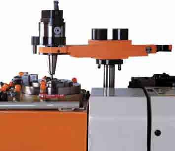
146 U-CENTER NC heads for facing, boring, threading and radiusing for machining centres
147 Index U-CENTER NC heads for facing, boring, threading and radiusing for machining centres GENERA FEATURES p U-DRIVE p. 5 ASSEMBY p. 5 SIZES p. 52 CHIP REMOVA CAPACITY p. 53 SUPPY p. 54 TOOHODERS AND HEADS p. 55 TECHNICA DATA p
148 U-CENTER General features o + 4 A U-CENTER U-CENTER boring and facing heads are designed for use on machines with automatic tool change, thus essentially on machining centres. The feed movement of the toolholder slide and the tool position, even during rotation, is controlled by a U-DRIVE motor drive unit. This unit is managed directly by an axis, known as U, of the machining centre numerical control. 3 CNC X Y Z 2 6 A machining centre set up in this way allows to carry out a series of different tooling procedures such as inner and outer turning, cutting grooves, tapered bores (even variable), concave and convex spokes, cylindrical and tapered threading, phonographic spirals, etc. W U 5. Power take-off 2. Servomotor 3. Transducer 4. imit microswitches 5. Arbor 6. U-CENTER head 48 KINEMATIC SYSTEM OF THE U-CENTER The kinematic system of all U-CENTERS is made up of a differential unit where one revolution of the power takeoff A corresponds to one.25 mm radial shift of the slide. The maximum allowed rate of 2 RPM at power take-off corresponds to a slide feed speed of 5 mm/min. The rated torque necessary for power take-off is 2 Nm. Between the servomotor mounted in the U-DRIVE unit and the toolholder slide of the U-CENTER is a radial reversal play of approximately.5 mm, thus in order to be precise positioning must take place in a single direction, and be included during programming.


 to allow to work at a high RPM without noticeable sways.")
149 General features D ANDREA COMPONENTS. Stationary body 2. Rotating body 3. Tool slide 4. Interchangeable arbor 5. Counterweights 6. Toolholders with interchangeable head 7. Coolant outlets 8. Power take-off A ; locking-release system ensures that the rotating body is secured to the fixed body when the U-CENTER is automatically removed from the spindle of the machining centre and placed in the tool magazine. BAANCING U-CENTER heads are designed with two counterweights (5) for automatic balancing, which move in the opposite direction to the slide (3) to allow to work at a high RPM without noticeable sways. The balanced heads are especially suited for precision tooling and to create diameters that require high rotation speed. A

, a transducer (2), the end of stroke (3), zero reference proximity")
150 U-CENTER U-DRIVE fig. 3 The U-DRIVE unit has to be properly mounted on the machine s headstock to allow for a safe engagement with the U-CENTER head (fig.3). The U-DRIVE unit contains the U axis servomotor (), a transducer (2), the end of stroke (3), zero reference proximity switches and the drive system to the U-CENTER head. The U-DRIVE can take different patterns according to the application on the machining centre; the most common are: angle (fig.4) or in line (fig.5) fig. 4 fig. 5
 mm 2. Preload spring (max load 2N) 3. Air intake for cleaning the power take-off 4.")
.5 - H A +.5 75 ±.2 3 6 5 U-DRIVE 6 -.")
151 Assembly D ANDREA ASSEMBY The manufacture and installation of the U-DRIVE must observe the measurements and tolerances indicated on the drawings. DATA. Spacer to adapt the U-DRIVE according to the measurement (X+.5) mm 2. Preload spring (max load 2N) 3. Air intake for cleaning the power take-off 4. Wedge clutch axial stroke from to 2 mm 5. Spring (max load 5 N) 6. Rotation lock disengage stroke 7. ock-release lever 8. Reference peg 9. Positioning ring A. Distance between the taper reference line and the surface of the U-CENTER head H. Height of the U-CENTER power take-off max 2 RPM 7 (X +.5).5 - H A ± U-DRIVE Ø 46 8 H X A Ø 5 ±.5 9 Ø Ø U-CENTER 5
152 R32 U-CENTER Sizes 5.5 O Ø A 5 C Ø B C D I ±. ±. Ø Ø Ø 7 -. Ø 8 Ø N ± Ø S T 75 ± ± E +.4 prof 2 F H M X P G Q 49 R (75) 4 5 Ø U 52 DATA UC 4 BH UC 6 BH UC 8 BH UC 2 BH ØA mm ØB mm C mm D mm E mm 2 2 F mm G (da N) H mm I mm 2 2 mm M mm n 4 M 5x n 8 M 5x n 4 M 6x2 n 26 M 6x2 ØN mm O mm P mm Q mm R mm ØS mm T mm ØU mm Xmm DATA. Maximum overall dimensions of balancing weights 2. Measurements for hollows 3. Rotation lock disengage stroke 4. Coolant intake 5. Coolant outlet 6. Centre of gravity
153 Chip removal capacity D ANDREA These parameters are indicative for normal working conditions on steel with a hardness of 6-2 HB, positive insert and cutting speed of 2 m/min. D mm U-CENTER 4/BH D U-CENTER 6/BH - 8/BH - 2/BH mm 5 5 U-CENTER 4/BH -6/BH U-CENTER 8/BH - 2/BH Chip section in mm 2 U-CENTER 4/BH.75.5 U-CENTER 6/BH.85.6 U-CENTER 8/BH U-CENTER 2/BH.75 D mm U-CENTER 4/BH 53 D U-CENTER 6/BH - 8/BH - 2/BH mm 5 5 U-CENTER 4/BH -6/BH 5 5 U-CENTER 8/BH - 2/BH Chip section in mm 2 U-CENTER 4/BH.5 U-CENTER 6/BH.65 U-CENTER 8/BH U-CENTER 2/BH
154 U-CENTER Supply K2 REF. K2 UC 4/BH K2 UC 6/BH K2 UC 8/BH K2 UC 2/BH CODE K3 consisting of: P P P P T 24 T 24 R REF. K3 UC 4/BH K3 UC 6/BH K3 UC 8/BH K3 UC 2/BH CODE ARBORS To order the U-CENTER arbor, it is necessary to draw-up the form on p. 56 REF. UC 4/BH UC 6/BH UC 8/BH UC 2/BH ISO 45 / 5 ISO 45 / 5 ISO 45 / 5 ISO 45 / 5
155 Toolholders and heads D ANDREA P P UC 4-6/BH UC 8-2/BH REF. CODE D H P P P P P P UC 4-6/BH UC 8-2/BH REF. CODE S P P P P T 24 D T 24 R T 24 T 24R A D H S F REF. CODE A D F UC 4-6/BH UC 8-2/BH T T 24 R T T 24 R CCMT CCMT
156 U-CENTER Technical data A Ø max 56 To order the U-CENTER supplied with arbor (A) it is necessary to enclose a filled copy of the following design, or the application layout. REQUESTED DATA U-CENTER mod.: Type of arbor (A): MACHINING CENTRE Trademark: Model: Spindle: Max. tool weight:
157 Technical data D ANDREA G P I K H F E Ø Ø C Ø D Ø B Ø A P P P TECHNICA DATA UC 4 BH UC 6 BH UC 8 BH UC 2 BH H mm inch K mm inch I mm inch mm inch Tool slide trasverse mm inch Feed mm/min. inch/min Rapid motion mm/min. inch/min Maximum speed RPM RPM Torque Nm lb ft Max. torque on take-off shaft Nm lb ft Radial force dan pound Unidirec. repeatability accuracy RP mm inch Weight with shank Kg pound Ø A mm inch Ø B mm inch Ø C mm inch Ø D mm inch E mm inch F mm inch G mm inch Boring accuracy H7 H7 H7 H7 H7 H7 H7 H7 Facing accuracy on tot. slide stroke mm inch Max. chip removal on C4 steel Facing mm 2 inch Boring mm 2 inch Roughness Ra µin


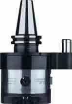
158 U-TRONIC Medium and large-sized NC heads for facing, boring, threading and radiusing


159 Index U-TRONIC Medium and large-sized NC heads for facing, boring, threading and radiusing GENERA FEATURES p. 6 COMPONENTS AND IMPORTANT WARNINGS p. 6 SIZES p EECTRIC COMPONENTS p ASSEMBY/GENERAITIES p. 68 U-TRONIC 8-2 BH ASSEMBY p. 69 FANGE-CONSTRUCTION EXAMPE p. 7 CHIP REMOVA CAPACITY p. 7 TOOHODERS p TECHNICA DATA p


160 U-TRONIC General features AXES CNC X Y Z W U M= motor T= transducer T U TRONIC M U T M W INTERFACE U-TRONIC are medium and large NC heads, controlled by the U axis of the CNC of the machine tool for inner and outer facing, undercutting, cylindrical and conical boring and threading, concave and convex radiusing machining, by interpolation with other machine axis. These heads can be fitted to boring machines, to machining centres and to special machines manually, automatically or by means of palletized systems. These heads are manufactured in 8 models, from ø 8 mm to mm and all of them have internal coolant supply. The versions ø 8 and 2 BH are provided with two counterweights which allow machining at high RPM with unsignificant vibrations. U-TRONIC special versions, with two slides and with self-balance counterweights can be supplied on request. Fixed toolholders are applied on the slide, with manual or automatic tool change. 6


161 Components and important warnings D ANDREA COMPONENTS. Stationary body 2. Rotating body 3. Tool slide 4. Gears 5. Bearings 6. Coolant way 7. Servomotor 8. Rotary transducer 9. imit switches. Connectors. Interchangeable arbor 2. Flange 6 IMPORTANT NOTE The kinematic system of the U-TRONIC is made up of a kinematic chain complete with differential or epicycloidal unit where: - U-TRONIC 8 and 2 BH one motor revolution=.25 mm radial shift of the slide. One revolution of the transducer =.25 mm radial shift of the slide. - U-TRONIC 325, 4, 5 and 63 one motor revolution=. mm radial shift of the slide. One revolution of the transducer = 2 mm radial shift of the slide. - U-TRONIC 8, one motor revolution=.4 mm radial shift of the slide. One revolution of the transducer = 2 mm radial shift of the slide. Between the transducer and the toolholder slide there is a max radial reversal play in the kinematic chain of approximately.5 mm, thus in order to be precise positioning must take place in a single direction, and be included during programming For safety reasons, install a microswitch on the machine that signals when the U-TRONIC is mounted and limits spindle rotation as follows: UT 8 BH max. RPM UT 2 BH max. RPM 8: per stroke mm RPM 6: per stroke from 25 to 37.5 mm UT S max. RPM 5 UT 5-4 S max. RPM 4 UT 5-5 S max. RPM 35 UT 5-63 S max. RPM 25 UT 8-8 S max. RPM 2 UT 8- S max. RPM 6
162 5 U-TRONIC Sizes U-TRONIC 8 BH 255 M2 prof.fil.2 E C ø C M6 prof.fil E2 Ø D Ø 5 Ø 8 Ø 6 H6 Ø prof A Ø ±. 3 ±. U-TRONIC 2 BH M2 prof.fil C Ø 275 Ø C 62 E Ø 5 Ø 8 Ø 6 H6 Ø prof M6 prof.fil.2 E2 Ø D A 6 ±. 6 ±. A = Coolant outlet C = Radial trasverse D = Coolant way E = Electric connectors Encoder-imit stop E2= Electric connectors Servomotor
163 Sizes D ANDREA U-TRONIC 3/325 S G Ø 25 Ø F Ø Mx M6x '3'' A B Ø 7 H7 Ø 4 Ø Ø 325 M8 prof.fil Ø H8 4 D E 5 44 E2 H gr C U-TRONIC 5/4 S G Ø M prof.fil.6 Mx 7 7'3'' A B H7 prof.9 Ø M2x.5 4 Ø 3 H7 Ø 2 Ø 242 Ø Ø M prof.fil.6 F Ø Ø Ø H gr H8 D E E2 C 4.5 A = Coolant outlet B = Presetting block C = Radial trasverse D = Coolant way E = Electric connectors Encoder-imit stop E2= Electric connectors Servomotor F =.5- BAR air intake for inner pressurization G = Cables way H = Camlock
164 U-TRONIC Sizes G Ø U-TRONIC 5/5 S A B M prof.fil.6 M2x.5 7 7'3'' H7 prof Mx Ø 3 H7 Ø 242 Ø 2 Ø Ø 5 M prof.fil F Ø H8 D E E2 H Ø C U-TRONIC 5/63 S 2 G Ø Ø 5 M prof.fil.6 25 H7 prof.9 9 Mx M2x.5 7 7'3'' A B Ø 3 H7 Ø 2 Ø 242 Ø M prof.fil.6 F Ø H8 D E 2 E2 5.7 Ø 25.4 H C 4.5 A = Coolant outlet B = Presetting block C = Radial trasverse D = Coolant way E = Electric connectors Encoder-imit stop E2= Electric connectors Servomotor F =.5- BAR air intake for inner pressurization G = Cables way H = Camlock gr.8
165 Sizes D ANDREA 26 U-TRONIC 8/8 S M24 prof.fil.4 M prof.fil G M24 prof.fil.4 A B H7 prof Ø 25 H7 Ø 32 Ø 382 Ø 5 H4 Ø 8 M2 prof.fil E2 M4x.5 D Ø C F Ø H H8 26 U-TRONIC 8/ S 435 M prof.fil.2 Ø G M24 prof.fil.4 A B 25 H7 prof.8 Ø Ø 25 H7 Ø 32 Ø 382 Ø 5 H4 65 M24 prof.fil M2 prof.fil.24 E2 M4x.5 5 D Ø C F Ø H H8 A = Coolant outlet B = Presetting block C = Radial trasverse D = Coolant way E2= Electric connectors Servomotor F =.5- BAR air intake for inner pressurization G = Cables way
166 U-TRONIC Electric components BURNDY CONNECTOR UTG6 6-9 SN BURNDY CONNECTOR UTG 6-9 PH BURNDY CONNECTOR UTG 4-2 PH BURNDY CONNECTOR UTG6 4-2 SN SIEMENS CONNECTOR 6FX23-OCE2 6FX23-OCE7 (DIGITA) SIEMENS CONNECTOR 6FX23-OCE IMIT SWITCH KW423K6U375 A B C U-TRONIC 8-2 BH E F D R G H J A C B T S M P K N V U BURNDY CONNECTOR UTG6 6-9 SN COD BURNDY CONNECTOR UTG 6-9 PH COD ENCODER (E) ROD 426-E/5 pulse/rev IMIT SWITCH KW423K6U375 SIEMENS A.C. SERVOMOTOR FT546-AK7 SIEMENS A.C. SERVOMOTOR FT644-A4K7 DIGITA Ua2 +5V Ua Ua Ua Ua _ Ua2 screen V +5V V ENCODER (E) ROD 426-E/25 pulse/rev PINK BUE RED BACK BROWN GREEN YEOW GRAY WHITE-BROWN.5 mm 2.5 mm 2 WHITE WHITE BROWN A B C D E F G H J K M BURNDY CONNECTOR UTG6 4-2 SN COD BURNDY CONNECTOR UTG 4-2 PH COD U-TRONIC 3/325 S 66 BURNDY CONNECTOR UTG 4-2 PH BURNDY CONNECTOR UTG6 4-2 SN BURNDY CONNECTOR UTG6 6-9 SN SIEMENS CONNECTOR 6FX23-OCE SIEMENS CONNECTOR 6FX23-OCE2 6FX23-OCE7 (DIGITA) BURNDY CONNECTOR UTG 6-9 PH IMIT SWITCH KW423K6U5 A B C E F D R G H J A C B T S M P K N V U BURNDY CONNECTOR UTG6 6-9 SN COD BURNDY CONNECTOR UTG 6-9 PH COD SIEMENS A.C. SERVOMOTOR FT534-AK7 SIEMENS A.C. SERVOMOTOR FT634-4AK7 DIGITA ENCODER (E) ROD 426-E/5 pulse/rev IMIT SWITCH KW423K6U5 Ua2 +5V Ua Ua Ua Ua Ua2 screen WHITE-BROWN.5 mm 2.5 mm 2 +5V PINK BUE RED BACK BROWN GREEN YEOW GRAY WHITE ENCODER (E) ROD 426-E/5 pulse/rev WHITE BROWN A B C D E F G H J K M BURNDY CONNECTOR UTG6 4-2 SN COD BURNDY CONNECTOR UTG 4-2 PH COD A= END OF STROKE B= EMERGENCY C= RESET (E): For digital servomotor, encoder on request
167 Electric components D ANDREA SIEMENS A.C. SERVOMOTOR FT546-AK7 SIEMENS A.C. SERVOMOTOR FT644-4AK7 DIGITA U-TRONIC 5/4-5/5-5/63 S A B C IMIT SWITCH KW423K6U E F D R G H J A C B T S M P K N V U BURNDY CONNECTOR UTG6 6-9 SN COD BURNDY CONNECTOR UTG 6-9 PH COD IMIT SWITCH KW423K6U5 ENCODER (E) ROD 426-E/5 pulse/rev BURNDY CONNECTOR UTG 6-9 PH BURNDY CONNECTOR UTG 4-2 PH BURNDY CONNECTOR UTG6 6-9 SN BURNDY CONNECTOR UTG6 4-2 SN SIEMENS CONNECTOR 6FX23-OCE2 6FX23-CE7 (DIGITA) SIEMENS CONNECTOR 6FX23-OCA Ua2 +5V Ua Ua Ua Ua Ua2 screen.5 mm 2 +5V.5 mm 2 WHITE ENCODER (E) ROD 426-E/5 pulse/rev PINK BUE RED BACK BROWN GREEN YEOW GRAY WHITE-BROWN WHITE BROWN A B C D E F G H J K M BURNDY CONNECTOR UTG6 4-2 SN COD BURNDY CONNECTOR UTG 4-2 PH COD U-TRONIC 8/8-8/ S SIEMENS A.C. SERVOMOTOR FT5 74-AF7 SIEMENS A.C. SERVOMOTOR FT684-84F7 DIGITA SIEMENS CONNECTOR 6FX23-OCA 6FX23-OCB (DIGITA) SIEMENS CONNECTOR 6FX23-OCA2 6FX23-OCE7 (DIGITA).3 m m IMIT SWITCH KW423K6U5 A B C E F D R G H J A C B T S M P K N V U CABES ENGTH = m. 67 IMIT SWITCH KW423K6U5 ENCODER (E) ROD 426-E/5 pulse/rev Ua2 PINK +5V BUE Ua RED Ua BACK Ua BROWN Ua GREEN - YEOW Ua2 GRAY screen WHITE-BROWN -.5 mm 2 +5V.5 mm 2 - WHITE ENCODER (E) ROD 426-E/5 pulse/rev WHITE BROWN A B C D E F G H J K M CABES ENGTH =,3 m. A= END OF STROKE B= EMERGENCY C= RESET (E): For digital servomotor, encoder on request


168 U-TRONIC Assembly/Generalities U-TRONIC BH U-TRONIC S CAMOCK The BH U-TRONICS are applied manually or automatically using the taper for rotation and a flange for fastening. The other U-TRONICS, fitted with rotation plate in place of the taper, are applied: a. manually, with a camlock flange for quick fastening b. automatically with palletized systems and special connectors. 68

 - Make the flange with support surfaces parallel in. mm tolerance. - Mount the U-TRONIC with the taper and the flange on the machine spindle.")
169 U-TRONIC 8-2 BH assembly D ANDREA C A B D A.8. X.8 E On machines with fixed spindle - Mount the U-TRONIC with the taper and without flange on the machine spindle and measure exactly the X distance with a tolerance of ±.5 mm. - Make the flange with X distance and a tolerance of ±.5 mm. - Mount the U-TRONIC with the taper and the flange on the machine spindle and tighten the screws. On machines with axial spindle stroke (boring machines) - Make the flange with support surfaces parallel in. mm tolerance. - Mount the U-TRONIC with the taper and the flange on the machine spindle. - Retract the spindle until the flange rests lightly against the front surface of the boring machine head. - Block the axial stroke of the boring machine spindle. - Tighten the flange screws. B = Center the boring machine spindle C = Flange D = Arbor E = Stud Bolt 69
170 U-TRONIC FANGE - Construction example C U-TRONIC 325 S 5.9 ±. 98 ±.5 98 ±.5. A A A.8 CAMOCK KIT 98 ±.5 98 ± '6" 45 ø ø B ø 65 M8 ø '3" +.5 D G n ø consisting of: n 4 camlock cams n 4 pins for cams n 4 springs for cams n key n M eyebolt F min. 4 E ± ±.5. A U-TRONIC S C A.8. A ø '8" 5 ±.5 5 ±.5 2 ±.5 2 ±.5 ø 5 B '3" ø ø CAMOCK KIT 76 M8 ø 3.5 D consisting of: n 6 camlock cams n 6 pins for cams n 6 springs for cams n key n 2 M6 eyebolt +.5 H n ± F ø min..8 5 E. B = Center the boring machine spindle C = Eyebolt D = Control with Gauge E = Size to control depending on the spindle protrusion F = Control wrench G = Bores min. depth 46 H= Bores min. depth 53
171 Chip removal capacity D ANDREA U-TRONIC 8-2 BH U-TRONIC 325 S D mm D mm UT 2/BH UT 325 S UT 8/BH TOO ENGTH mm mm 2,4 mm 2,8 mm 2 TOO ENGTH mm mm 2 4 mm mm 2 5 U-TRONIC S U-TRONIC 8- S D mm D mm UT 5-63 S UT 8- S UT 5-5 S UT 8-8 S UT 5-4 S TOO ENGTH mm mm 2 6 mm 2 4 mm 2 TOO ENGTH mm mm 2 mm 2 7 mm 2 5 mm These parameters are indicative for normal working conditions on steel with a hardness of 6-2 HB, tool with a positive rake angle y= + 6 and lead angle = 75 (average Ks = 2N/mm 2 ) cutting speed = 2 m/min. Optimal value and working time will be determined by tests. For a good chip removal and for the chip break control, it is advised: a : f = 6 8 a = cutting depth (mm) f = feed (mm/rev)
172 U-TRONIC Toolholders U-TRONIC 8-2 BH P P T 24 R ARBOR T 24 P U-TRONIC FANGE P K3 consisting of: P P P P T 24 T 24 R REF. K3 UT 8/BH K3 UT 2/BH CODE ARBORS 72 REF. UT 8/BH UT 2/BH ISO 4 - ISO 45 - ISO 5 ISO 4 - ISO 45 - ISO 5
173 Toolholders and heads D ANDREA P P UT 8-2/BH REF. CODE D H P P UT 8-2/BH REF. CODE S P P T 24 D T 24 R 95 A D H P P S T 24 T 24R F REF. CODE A D F 73 UT 8-2/BH T T 24 R CCMT
174 U-TRONIC Toolholders U-TRONIC S B5 B 5 25x25 TU 8/ CA ISO56 B MR PC.5 TP 8/9.5 FANGE U-TRONIC B 2 PC K3 consisting of: B B2 B5 MR TU REF. UT3/325S UT5/4S UT5/5S UT5/63S UT8/8S UT8/S Toolholder with automatic tool change B5 UT5/4S REF. UT5/5S B5 HSK - A63 - A UT5/63S B5 DIN6987-A - B5 UT8/8S B5 MAS BT5 UT8/S
175 Toolholders D ANDREA A H B/B2 Ø d H7 Ø d2 REF. CODE A d d2 H kg UT3/325S B UT B2 UT UT5/4S B UT UT5/5S UT5/63S B2 UT UT8/8S B UT UT8/S B2 UT Ø d2 A H Ø d H7 H B5 REF. CODE A d d2 H H kg UT3/325S B5 UT UT5/4S UT5/5S B5 UT UT5/63S UT8/8S UT8/S B5 UT Ø d MHD' 8 Ø d2 MR REF. CODE d d2 2 kg UT3/325S MR 5/ UT5/4S UT5/5S MR 63/ UT5/63S UT8/8S UT8/S MR 8/ MHD' Ø 95 TU REF. CODE kg UT3/325S UT5/4S UT5/5S TU 8/ UT5/63S UT8/8S UT8/S d2 MHD' TP UT3/325S UT5/4S UT5/5S UT5/63S UT8/8S UT8/S REF. CODE d2 kg TP 8/ TP 8/ CA 59 PC Use 6CA ISO56 cartridges (see p.77) B REF. CODE B kg UT3/325S UT5/4S PC UT5/5S PC UT5/63S PC UT8/8S UT8/S PC
176 U-TRONIC Technical data H P " 2.8" D D C/2 C/2 255 " 255 " P D P P ø E max. ø F max. P P P ø M max. ø N max. C/2 C/2 P P2 P D C B ø F max. ø M max. ø N max. S H 76 TECHNICA DATA UT 8 BH UT 2 BH UT 325 S Radial trasverse C mm inch Feed mm/min. inch/min Rapid trasverse mm/min. inch/min Maximum rotation min - RPM 8 5 Torque da Nm lb ft Radial force da N pound Weight Kg pound Ø B mm inch Ø D mm inch H mm inch S mm inch Ø E x P mm inch 24 x x 3 35 x x Ø F x P mm inch 36 x x 3 45 x x 3 65 x x.5 Ø M x P2 mm inch 25 x x x 2 7 x x x 5.75 Ø N x P mm inch 65 x x x x x 24 2 x 9.45 Repeatibility accuracy mm inch Boring accuracy H7 H7 H7 H7 H7 H7 Facing accuracy mm inch Max. chip removal on C4 steel mm 2 inch Roughness Ra µin
177 Technical data D ANDREA UT 5 4 S UT 5 5 S UT 5 63 S UT 8 8 S UT 8 S x x 6 x x 6 25 x 5 49 x 6 6 x 6 63 x x 6 79 x x x x x x x x x x x x x.6 85 x x.6 5 x x.6 25 x 37\ 49.2 x x x H7 H7 H7 H7 H7 H7 H7 H7 H7 H
178 INSERTS
179 INSERTS


180 INSERTS 8 WCGT 7 r d s SIZES CARBIDE CERMET COATED REF. CERMET d s r DP 3 DK DC DCT WCGT 22.2 TS 2-TS TORX T6 WCGT 24.4 * * TS 2 for B...6 / TS 2 for B CCGT 7 r d s SIZES CARBIDE CERMET COATED REF. CERMET d s r DP 3 DK DC DCT CCGT 62 CCGT TS 25 TORX T8 CCGT CCGT 9T TS 4 TORX T5 CCGT 9T TPGX r d s 8 SIZES CARBIDE CERMET COATED REF. CERMET d s r DP 3 DK DC DC DCT TPGX 92 TPGX CS 25 T TORX T8 TPGX TPGX 3 CS 389T TORX T8 TPGX TPGX 34.4


181 D ANDREA 6 TPGX r d s SINTERED CUBIC BORON SIZES REF. DIAMOND NITRIDE d s r D2 MDC D2 CBN D25 CBN TPGX CS 25 T TORX T8 TPGX TPGX CS 389T TORX T8 TPGX CCMT 7 d r s CARBIDE CVD COATED SIZES REF. CARBIDE d s r DP 3 DP R CCMT TS 25 TORX T8 CCMT CCMT 9T TS 4 TORX T5 CCMT 9T38.8 CCMT TS 5 TORX T25 CCMT TORX SCREW TORX WRENCH D M REF. CODE M D REF. CODE 8 TS M 2x TORX TO TS M 2x TORX TO CS 25 T M 2.5x TORX TO CS 389 T M 3x TORX TO TS M 2.5x TORX TO TS M 4x TORX T TS M 5x TORX T
182 INSERTS X6...R S X6... On request P REF. CODE S P REF. CODE S P X6 62-R X X6 62-3R X X6 62-6R X X R X X R X X R X X6 62-3R X X R X X6 9T3-45R X6 9T X6 9T3-55R X6 9T X6 9T3-55R X6 9T X6...R..R R X6...R.. P On request REF. CODE R P REF. CODE R P X6 62-RR X6 62-R X6 62-R5R X6 62-R X6 9T3-R2R X6 9T3-R X6 9T3-R25R X6 9T3-R TORX SCREW TORX WRENCH D M 82 REF. CODE M D REF. CODE TS M 2.5 x TORX T TS M 3 x TORX T
183 Grades for inserts D ANDREA ISO CEMENTED CARBIDE CERMET COATED CERMET CVD COATED CARBIDE P DC P DC DCT DPR P2 P3 DP3 P4 K K DK DC DCT DPR K2 DP3 K3 QUAITY APPICATIONS DP3 Roughing and finishing ow carbon steel - stainless steels Cemented carbide DK Roughing and finishing Finishing Aluminium alloy Cast iron CVD coated carbide DPR Roughing Steels, alloy steels and cast iron Cermet DC Finishing High alloyed steel DC Finishing Alloy steels and cast iron Coated Cermet DCT Finishing Alloy steels, stainless steels and cast iron Polycrystalline diamond D2 MDC Finishing Aluminium alloys, non-ferrous materials and non-metals 83 Cubic boron nitride D2 CBN D25 CBN Finishing Finishing High hardness steels (over 5 HRC) (it may replace the grinding) High hardness steel (over 5 HRC) and interrupted cutting (it may replace the grinding)


184 ACCESSORIES AND SPARE PARTS
185 ACCESSORIES AND SPARE PARTS

186 ACCESSORIES AND SPARE PARTS ISO 7388/2-A - DIN d d2 d3 d4 a REF. CODE ISO d d2 d3 d4 a M ISO 7388/2-A M DIN M ISO 7388/2-B - ANSI B.5 5 d d2 d3 d4 a REF. CODE ISO d d2 d3 d4 a M ISO 7388/2-B M ANSI B M MAS 43 BT d d2 d3 d4 a 86 REF. CODE ISO d d2 d3 d4 a M MAS43 BT M M M M MAS43 BT M M M
187 D ANDREA HSK 2 REF. CODE α CODE 2 HSK ± 5 4 HSK ± 5 6 HSK ± 5 8 HSK ±

188 ACCESSORIES AND SPARE PARTS ER collet ER.. DIN 6499-B 8 D d D2. REF. d D D2 ER.5 ~ ER 6.5 ~ ER 2 ~ ER 25 ~ ER 32 2 ~ ER 4 3 ~ RANGE ER ER6 ER2 ER25 ER32 ER SET ER REF. Ø CODE SET ER/ SET ER6/ SET ER2/ SET ER25/ SET ER32/ SET ER4/

189 ER.. DIN 6499-B ER ultra-precise collet D ANDREA 8 D d D2.3 REF. d D D2 ER 6.UP.5 ~ ER 25.UP ~ ER 32.UP 2 ~ ER 4.UP 3 ~ RANGE ER6 ER25 ER32 ER On request 89
190 ACCESSORIES AND SPARE PARTS Tapping collets with axial compensation ET-- ER.. E 8 D d For TOPRUN spindles, use ring-nuts shown in the chart REF. CODE d D E ET--ER (M2 ~ M2) ET--ER (M4 ~ M6) ET--ER4 (M8 ~ M2) On request 9
 49 6 8 566 6 x 4.9 M8 M6 6 27.5 45 6 49 6 8 567 7 x 5.5 M6 M 49 6 8 52545 4.5 x 3.4 M4 M6 49 6 8 52555 5.5 x 4.3 M7 M5 ER 25-GB 49 6 8 5256 6 x 4.")
191 ER.. -GB Tapping collets without axial compensation D ANDREA 8 D c d For TOPRUN spindles, use ring-nuts shown in the chart REF. CODE (d Ø x c ) DIN 37 DIN D x 3.4 M4 M x 4.3 M7 ER 6-GB M5 (M4 ~ M) x 4.9 M8 M x 5.5 M6 M x 3.4 M4 M x 4.3 M7 M5 ER 25-GB x 4.9 M8 M6 (M4 ~ M6) x 5.5 M x 7 M x 9 M x 9 M x 3.4 M4 M x 4.3 M x 4.9 M5 M6 M8 ER 32-GB x 5.5 M (M4 ~ M2) x 7 M x 9 M x 9 M x M x 2 M x 5.5 M x 7 M x 9 M x 9 M6 ER 4-GB x M (M ~ M27) x 2 M2 On request x 4.5 M22 M x 6 M27 9
 M5 3 9 7 7 2.5 49 5 6 649 6 x 4.9 M8 M8 M6 49 5 6 755 7 x 5.5 M M 49 5 6 97 9 x 7 M2 M2 49 5 6 2649 6 x 4.9 M5 M6 M8 M8 49 5 6 2755 7 x 5.")
192 ACCESSORIES AND SPARE PARTS Quick change tap holders without torque clutch BFC 3 2 D2 c d D REF. CODE (d Ø x c ) DIN 37 DIN 374 DIN 376 D D x 2.7 M3 M5 M x 3.4 M4 M6 M6 BFC x 4.3 M7 M7 (M3 ~ 2) M x 4.9 M8 M8 M x 5.5 M M x 7 M2 M x 4.9 M5 M6 M8 M x 5.5 M M BFC x 7 M2 M2 (M6 ~ 2) x 9 M4 M x 9 M6 M x M8 M x 2 M2 M x 9 M4 M x 9 M6 M x M8 M x 2 M2 M2 BFC x 4.5 M22 M (M4 ~ 33) M24 M x 6 M27 M x 8 M3 M x 2 M33 M33 On request 92
 M6 49 5 7 755 7 x 5.5 M M 49 5 7 862 8 x 6.2 M8 49 5 7 97 9 x 7 M2 M2 49 5 7 8 x 8 M 49 5 7 2649 6 x 4.")
193 BFS Quick change tap holders with torque clutch D ANDREA 3 2 D2 c d D REF. CODE (d Ø x c ) DIN 37 DIN 374 DIN 376 D D x 2.7 M3 M5 M x 3 M x 3.4 M4 M6 M x 4.3 M7 M7 BFS M x 4.9 M8 M8 (M3 ~ 2) M x 5.5 M M x 6.2 M x 7 M2 M x 8 M x 4.9 M5 M6 M8 M x 5.5 M M x 6.2 M8 BFS x 7 M2 M2 (M6 ~ 2) x 8 M x 9 M4 M x 9 M6 M x M8 M x 2 M2 M x 9 M4 M x 9 M6 M x M8 M x 2 M2 M2 BFS3 M22 M (M4 ~ 33) x 4.5 M24 M x 6 M27 M x 8 M3 M x 2 M33 M33 On request 93
194 ACCESSORIES AND SPARE PARTS Bushes for ultra-tight spindle RC Ø d2 ø d FORCE (d2) REF. CODE d RC RC RC RC RC RC RC RC RC RC RC RC RC RC RC RC RC RC RC RC RC RC 3/4./ /4 RC 3/4.5/ /6 3/4 RC 3/4.3/ /8 RC 3/4.7/ /6 5 RC 3/4./ /2 RC 3/4.5/ /8 RC -/4.3/ /8 RC -/4./ /2 -/4 RC -/4.5/ /8 63 RC -/4.3/ /4 RC -/
195 Reduction D ANDREA D.. Ø 6 g6 Ø d H6 REF. CODE ø d H6 D D D D
196 ACCESSORIES AND SPARE PARTS MHD SYSTEM MHD OR d d2 OR REF. CODE d d2 CODE CODE OR MHD MHD MHD MHD MHD MHD 5 (RD5/..) MHD MHD TS - BS TS../ BS.. S.. SSQC REF. CODE CODE 2 CODE 3 TS... / TS... / TS / BS.../ TS / BS.../ TS / BS.../ TS... / TS... / TS... /
197 MHD D ANDREA BPS 4 SSQC S REF. CODE CODE 2 CODE 3 CODE 4 CODE 5 CODE 6 BPS BPS
198 ACCESSORIES AND SPARE PARTS MHD BM SF.. SFQC BF.. SF.. SFQC TRM/BF TRM REF. CODE CODE 2 CODE 3 CODE 4 CODE 5 TRM TRM / BF.../ TRM / BF.../ TRM / BF.../ TRM / BF.../ TRM / BF.../ TRM TRM.. SF.. SFQC REF. CODE CODE 2 CODE 3 TRM TRM TRM SFQC BPS 3 SF REF. CODE CODE 2 CODE 3 CODE 4 BPS BPS
199 MHD D ANDREA PS REF. CODE PS PS PS PS PS PS PS P.. REF. CODE P P P P P P P REF. CODE CODE 2 P P REF. CODE P
200 ACCESSORIES AND SPARE PARTS MHD 2 3 PE ER DIN 6499 REF. CODE CODE 2 CODE 3 PE 6 / ERM PE 2 / ER6M PE 25 / ER2M PE 32 / ER25M PE 4 / ER PE 5 / ER PE 5 / ER PE 63 / ER PE 63 / ER AW DIN 835 B-E REF. METRIC CODE CODE 2 REF. INCH CODE CODE 2 AW 5/ AW 5 / AW 5/ AW 5 3/ AW 5/ AW 5 / AW 5/ AW 5 5/ AW 5/ AW 5 3/ AW 5/ AW 63 / AW 5/ AW 63 5/ AW 5/ AW 63 3/ AW 63/ AW AW 63/ AW 63 - / AW 63/ AW 8 - / AW 63/ AW AW 8/ AM 3 2 REF. REF. CODE REF. 2 CODE 2 CODE 3 AM 5/M3-2 RAM 5/M WFK 5B/A AM 5/M8-2 RAM 5/M WFK 225B/A AM 63/M3-2 RAM 63/M WFK 5B/A AM 63/M8-2 RAM 63/M WFK 225B/A
201 MHD D ANDREA 5 4 PF METRIC REF. CODE CODE 2 CODE 3 CODE 4 CODE 5 PF 5/ PF 5/22 PF 4/ PF 5/ PF 5/ PF 63/ PF 63/ PF 8/ PF 8/ PF 8/ INCH 2 REF. CODE CODE 2 CODE 3 CODE 5 PF 5 3/ PF PF 63 3/ PF PF 63 - / PF 8 - / PF CM DIN 228 A REF. CODE CM 5/ CM 5/ CM 5/ CM 63/ CM 63/
202 ACCESSORIES AND SPARE PARTS TOPRUN ER 4 d d2 2 REF. CODE d CODE 2 d2 CODE 3 CODE 4 ER ~ ~ ER ~ ~ ER ~ ~ ER ~ ~ FORCE REF. METRIC CODE CODE 2 FORCE FORCE REF. INCH CODE CODE 2 FORCE 3/ FORCE - / FORCE 2 33 d 2 33 d fig. fig fig. REF. METRIC CODE d VCR 2 HSK ~ 2 VCR 2 MHD ~ ~ 2 VCR 32 HSK ~ 2 VCR 32 MHD ~ 32 2 VCR 2 DIN/BT ~ ~ ~ 2 2 VCR 32 DIN/BT ~ ~ ~ 2 2 VCR 32 DIN/BT ~ ~ 32 fig. REF. INCH CODE d VCR 3/4 HSK /4 ~ 7/6 VCR 3/4 MHD /2 ~ 3/ /8 ~ /2 VCR -/4 HSK /8 ~ 3/4 VCR -/4 MHD ~ -/4 2 VCR 3/4 CAT /4 ~ 7/ /2 ~ 3/ /8 ~ /2 2 VCR -/4 CAT /8 ~ 3/ ~ -/4
203 TOPRUN 2 D ANDREA WD REF. METRIC CODE WD WD WD 2 9 WD WD WD WD WD WD REF. INCH CODE WD 3/ WD / WD 5/ WD 3/ WD WD -/ WN REF. CODE CODE 2 WN WN WN WN
204 ACCESSORIES AND SPARE PARTS TOPRUN PFS 2 3 REF. CODE CODE 2 CODE 3 METRIC PFS PFS PFS PFS PFS REF. INCH CODE CODE 2 CODE 3 PFS 3/ PFS PFS -/ PFS -/ TR TR REF. CODE CODE 2 CODE 3 TR TR
205 D ANDREA 25
206 TECHNICA DATA
207 Index TECHNICA DATA INFO CUTTING CONDITIONS p ARBORS STANDARDS p WinTool WINTOO p. 28
208 TECHNICA DATA Suggested cutting conditions for roughing operations with double-bit boring bars MHD cutting speed Vc= sfm feed f= ipr (twin cutters) material boring bar working diameter insert radius dimensions conditions D <.5 D =.5~4 D > 4.72 R =.8 R =.6 R =.3 / d = 2.5 good carbon steel / d = 4 normal HB 2 / d = 6.3 difficult / d = 2.5 good carbon steel / d = 4 normal HB > 2 / d = 6.3 difficult / d = 2.5 good stainless steel / d = 4 normal AISI / d = 6.3 difficult / d = 2.5 good cast iron / d = 4 normal / d = 6.3 difficult / d = 2.5 good aluminium / d = 4 normal / d = 6.3 difficult Twin cutters at the same cutting diameter d D cutting working max. cutting depth range depth ap = inch Ø = inch steel cast iron, aluminium d B ap Twin cutters at different cutting diameters It s advisable to start with B hole the boring bar diameter d. N ATTENTION: For boring operations at different diameters, reduce to a half the feed indicated on the above table. 28
209 MHD Suggested cutting conditions for boring operations with Testarossa and micrometric boring bars D ANDREA cutting feed f= ipr material boring bar working speed insert radius insert cutting dimensions conditions Vc= sfm R =. R =.8 R =.6 quality depth / d = 2.5 good DC carbon steel / d = 4 normal HB 2 / d = 6.3 difficult DP3 / d = 2.5 good DC carbon steel / d = 4 normal HB > 2 / d = 6.3 difficult DC / d = 2.5 good stainless steel / d = 4 normal DP3 AISI / d = 6.3 difficult ap / d = 2.5 good DC cast iron / d = 4 normal / d = 6.3 difficult DK / d = 2.5 good aluminium / d = 4 normal DK / d = 6.3 difficult steel / d = 2.5 good HCR > 5 / d = 4 normal D2CBN d CACUATION FORMUAS FOR BORING Vc cutting speed (sfm) D bore diameter (inch) n spindle revolution (rpm) VF feed rate (ipm) f feed (ipr) pi pi D n Vc = 2 Vc 2 n = pi D VF = n f 29
210 TECHNICA DATA Arbors standards HSK DIN A B d2 d l l HSK-A d d2 l HSK-B d d2 l C D d2 d d2 d l l HSK-C d d2 l HSK-D d d2 l E F d2 d d2 d d2 d l l HSK-E d d2 l HSK-F d d2 l
211 HSK DIN Arbors standards D ANDREA l4 l f f3 DIN A-E +.2 ø +.9 h2 d d2 d5 d6 d4 d d d2 b3 b l5 f4 6 ±5' h h2 h f2 l l8 f f3 l7 d d2 d5 d6 d4 d d d2 HSK b b2 H b3 H d H d d4 H d5 H d d max d d d f f2 min f3 ± f h h l f4 ± f2 l l l l6 JS l l
212 e2 e e TECHNICA DATA Arbors standards DIN 6987 l f2 DIN 6987 A-B f3 f 8 7'5" a 7 l6 l7 l5 d d3 d2 d8 d7 d6 d5 b l2 l3 6 ±5' l5 d ±3' ISO a ± b H d d2 M2 M6 M2 M24 d3 H d5 ± d d d8 max d e ± e2 max f ±..... f2 min f l l l3 min l l l
213 e2 e e MAS 43 BT Arbors standards D ANDREA MAS 43 BT A-B l f2 f 8 7'5" a f3 d7 l4 l4 d d3 d2 d4 d5 d6 b l2 l3 f4 f5 6-3' d ±3' ISO a ± b H d d2 M 2 M 2 M 6 M 2 M 24 d3 H d d5 H d d d e ± e2 max f ± f f3 min f f l ± l l3 min l
214 TECHNICA DATA Arbors standards ANSI/CAT METRIC - CAT INCH l f 9.5±.5.±. 5.87±.5 8 7'5" (3.8) 7 l4 l5 d d3 d2 d7 d6 d5 d4 ø 9.5 b l l3 6 ±5' ANSI/CAT METRIC ISO b d d2 M 6 M 2 M 24 d3 H d4 ± d d d7 ± f ± l l l3 min l l CAT INCH ISO b d d2 UNC 5/8 - UNC 3/4 - UNC d d4 ± d d d7 ± f ± l l l l l
215 DIN 28 - NMTB Arbors standards D ANDREA l k l2 a '5" b ø d d2 d5 d4 l7 l7 ISO 4 OTT l6 d7 l4 DIN 28 ISO a ± b H d d2 a d4 M 2 M 6 M 2 M 24 d d k ± l l l l l7 max NMTB ISO 4 5 a ± b H d d2 a d4 UNC 5/8- UNC d d k ±.5 2 l l l l6 5 l7 max
216 TECHNICA DATA Arbors standards DIN 228/A DIN 227 DIN 228/B DIN 86 DIN 228/A l a l a l6 b DIN 227 l2 45 l7 c/2 d d4 d8 d9 d l5 l3 MORSE 4 4 SIP a b d c/ d d4 max d8 7 7 d9 M 6 M 4 l max l2 9 9 l3 min l l6 5 5 l l7 l6 a DIN 228/B DIN 86 c/2 d6 d b s r l9 l8 26 MORSE 4 5 a b H c/ d d6 max l l7 max l l r2 8 s
217 a R8 METRIC/INCH Arbors standards D ANDREA l2 l R8 r d2 b d d4 d3 R8 METRIC INCH a b ± d d d3 M 2 UNF 7/6-2 d l l2 min r


218 TECHNICA DATA WINTOO Search by Tool list Active comp. Class Ident-No Caption Pages Assembled tools Ident-No Machine Caption Design Sort <empty record> It allows to be graphically constructed in a short period of time, showing the complete composition of the MODUHARD ANDREA tools, including dimensions, weight and the list of components. Zoom picture Italian English German 28
SENSITIV T-TA. Boring and facing heads with manual and automatic feed
 SENSITIV T-T Boring and facing heads with manual and automatic feed 8 SENSITIV T-T General features The line of T-T boring and facing heads is provided with radial feed movement of the radial slide while
Index SENSITIV T-TA SENSITIV T-TA. GENERAL FEATURES p COMPONENTS AND ASSEMBLY p SUPPLY p ARBORS p ACCESSORIES p.
 Index SENSITIV T-T Boring and facing heads with manual and automatic feed SENSITIV T-T Boring and facing heads with manual and automatic feed GENERL ETURES p. 120 COMPONENTS N SSEMBLY p. 121 SUPPLY p.
Metalworking ETP HYDRO-GRIP. Achieve Excellence through Simplicity. Hydraulic high precision toolholders
 Metalworking ETP HYDRO-GRIP Hydraulic high precision toolholders Achieve Excellence through Simplicity ETP HYDRO-GRIP Hydraulic high precision toolholders HYDRO-GRIP high precision tool holders are your
Metalworking ETP HYDRO-GRIP. Achieve Excellence through Simplicity. Hydraulic high precision toolholders
 Metalworking ETP HYDRO-GRIP Hydraulic high precision toolholders Achieve Excellence through Simplicity 2017 ETP HYDRO-GRIP Hydraulic high precision toolholders HYDRO-GRIP high precision tool holders are
Clamping Tools
 Clamping Tools Drill chuck Tapping chuck/ tapping machines Taper bore tools HSK inserts Tool holder for lathes Tool pre-setter 1 1.3 1.8 Reduction sleeves Spindle Sleeves Ejector Drifts Adapter sleeves
Driven Toolholders for MAZAK Machines
 Driven Toolholders for MAZAK Machines We do Specials! Manufacturer of Precision Tools since 1974 Table of Contents Type Page Driven Toolholders QTNX 100 + SQT 10 8-15 QTNX 200 / 250 + SQT 15 + SQ 200 /
HIGH PRECISION HIGH PERFORMANCE
 Tool holders www.haimer-usa.com HIGH PRECISION HIGH PERFORMANCE HAIMER Family owned & operated since 1977 Global Headquarters located in Igenhausen Germany North America operation and stocking facility
BEST OF 2014 January December
 Best of 2014 BEST OF 2014 January December 2405 K POWER CHUCK 3274 SELF-CENTRING SCROLL CHUCK 3 JAW 3, 60o serrations, through hole. Interchangeable with Kitagawa type B-200 Cast iron, plain back, front
Accessories, spare parts and measuring equipment
 Accessories, spare parts and measuring equipment The broad range of accessories, spare parts and measuring equipment represents a useful addition to the range of actual clamping tools and offers spare
SHRINK FIT CHUCKS CAT BT HSK CAPTO.
 SHRINK FIT CHUCKS CAT BT HSK CAPTO www.haimer.com HAIMER SHRINK FIT TECHNOLOGY Features Benefits 360 Clamping, Multiple planes Precision bore, no wear components No mechanical moving parts Induction shrink
ER Collets Nuts Disks
 Collets Nuts Disks 1 Collets - Features Benefits 2 Concentricity T.I.R. 3 Assembly Instructions 4 8 8-UP 8-MB 5 11 11-UP 11-MB 11-ND 6 16 16-UP 16-MB 7 20 20-UP 8 25 25-UP 9 32 32-UP 10 40 40-UP 12 50
Good reasons to use Albrecht drill chucks
 3 * Good reasons to use Albrecht drill chucks Quality 2-phase quality control e.g. 100% run-out accuracy test (similar to DIN 10888) parts made to fit each other exactly working parts are case-hardened
CTR Counterboring Tools
 CTR Counterboring Tools Primary Application Designed for high production screw head counterbores and similar counterboring operations. The S2 S inserts produce a precise 90 bottom. The ground radial land
BEST OF 2015 January December
 BISON opens its new manufacturing facility improving quality and service 53,000 sq. metre site 33,600 sq. metre of manufacturing State of the art design and manufacturing under one roof BEST OF 2015 January
Tooling for Swiss Automatics
 Tooling for Swiss Automatics MANUFACTURED IN SWITZERLAND Swiss Precision Tools I S O 9 0 0 1 CERTIFIED SWISS PRECISION SWISS QUALITY Providing tolerances unmatched in the industry TIR (in) REGO-FIX Cylindrical
HSK F80 MAKINO S HRINK FIT C H UCK S
 Haimer F80 Makino 4.5 HSK F80 MAKINO S HRINK FIT C H UCK S M6 Thread for balancing screws D1 D2 CERTIFICATE OF QUALITY A 10mm L Adjustable back-up screw with fl ats for coolant drainage from diam. 1/4
U-CENTER. NC heads for facing, boring, threading and radiusing for machining centres
 U-CENTER NC heads for facing, boring, threading and radiusing for machining centres 8 U-CENTER General features o + 4 1 A U-CENTER U-CENTER boring and facing heads are designed for use on machines with
HPI - PIONEER Premium Tool Holding & Work Holding SG - Second Generation Tool Holding System
 HPI - PIONEER Premium Holding & Work Holding SG - Second Generation Holding System The Pioneer Group We have been in the metal cutting industry for over three decades and contributed to the progress of
enduring. Drill Chucks NC-Tooling 2013/2014
 enduring. Drill Chucks NC-Tooling 2013/2014 www.roehm.biz DRILL CHUCKS - NC-TOOLING Keyless drill chucks EXTRA 1004 EXTRA-RV 1005 SUPRA 1006 SUPRA-SK 1008 SUPRA-SK E 1008 SPIRO - SPIRO-SK 1009 Key-type
ACE LOCK Milling Chucks
 ACE LOCK Milling Chucks Run-out accuracy: 10 µm/0.0004 at the distance of 100 mm/4.00 from the end of the holder. Milling Chucks Spiral slits are precision-machined with a laser securely hold the cutter
CAT PG 5 TC PG 6 BT PG 7 CYL PG 8 HSK PG 9 REGO-FIX CAPTO PG 10 REGO-PLUS CAT+ PG
 powrgrip System 1 powrgrip Toolholders - Features Benefits 2 Features Benefits 3 Information 4 CAT Toolholders 5 TC Toolholders 6 BT Toolholders 7 CY Toolholders 8 HSK Toolholders 9 REGO-FIX CAPTO Toolholders
PRECI-FLEX HAAS. The Flexible Tool System. EXSYS Tool, Inc. T: P: P:
 PRECI-FLEX The Flexible Tool System HAAS EXSYS Tool, Inc. T:800.397.9748 P:352.588.4345 P:352.588.4821 www.exsys-tool.com About Us WHO IS EPPINGER? Eppinger CNC tool holders to DIN 69880 (shaft diameters
1 Collets and collet sleeves
 1 1.3 Wibemo - Honing sleeve 1.4 Wibemo - Extenso collets 1.6 Wibemo - Croco collets 1.10 Wibemo - CuBe collets 1.11 Wibemo - Phenol collets 1.12 Custom made collets 1.18 Wibemo - Wifex collets 1.22 Tornos
PRODUCT CATALOGUE 2015
 PRODUCT CATALOGUE 2015 INTRODUCTION Terms and conditions WE HAVE THE KNOWLEDGE, THE EXPERIENCE AND THE SOLUTIONS! SPV Spintec aims to be your complete supplier and partner when it comes to processing in
DV Shank Tools DV40...F2 F37 DV50...F38 F71
 DV Shank Tools DV40..................................................................................F2 F37 DV50.................................................................................F38 F71
Stub Mill Holders, Boring Head, Blank Bar
 Stub Mill Holders, Boring Head, Blank Bar Current Promotion Scan these QR Codes Featured Video 119 Stub Mill Holders Stub Mill Holder Features Our Stub Mill Holders feature hardened and ground tapers,
Modules for fine machining. Guhring modules 6x6 and 4x4. NEW: Module 6x6
 NEW: Module 6x6 simple, quick and highly accurate setting of 6-fluted tools minimal tension thanks to 6 setting elements perfect balancing with 6 balancing screws Modules for fine machining Guhring modules
Swiss Automatic Tooling
 Swiss Automatic Tooling 1 Collets - Features Benefits 2 Concentricity T.I.R. 3 Assembly Instructions 4 8 8-UP 8-MB 5 11 11-UP 11-MB 11-ND 6 16 16-UP 16-MB 7 20 20-UP 8 25 25-UP 9 Metallic Sealed Collets
Live and Dead Centres
 s w i t z e r l a n d Live and Dead Centres 1. Live-Centres 1.1 Main-Line ROTOR Main-Line, the approved top of the range for lathes and grinding machines. Very precise and robust construction. Made for
FOR QUALITY, VALUE AND SERVICE CALL YOUR KAR DISTRIBUTOR TODAY!
 INTROUCTORY OFFER CAT Shank Tools ER Collet Chucks End Mill Holders Shell Mill Adapters Jacobs Adapters Integral Shank rill Chucks Morse Adapters Boring Bar Blanks Tightening Fixtures Universal H/V CNC
Industrial Drill Chucks & Live Centers
 Since 1957 Industrial Drill Chucks & Live Centers 2 From our headquarters in the province of Barcelona, Spain, Llambrich Precision, S.L. has been designing and manufacturing drill chucks and machine tool
HSS ground for steel to 900 N/mm 2, aluminium alloys, brass, bronze. Use For producing screw through-holes DIN EN 20273,
 Drilling Tools Step drills 184 Step drills T - Countersink angle - With straight shank - Cone envelope grind - Web-thinned chisel edge and surface treatment For producing threaded core holes and countersinks
CALL US WITH YOUR MACHINE MAKE & MODEL. WHETHER YOU NEED COOLANT THRU OR SOLID, WE WILL FIND THE RETENTION KNOB FOR YOU!
 RETENTION KNOBS For CAT40, CAT50, BT0, BT40 & BT50 CAT40 Retention Knobs 5/8 Description DWG. T A L HOLE? Socket X70A 40EA / A45.440(C.8) A A.65 45.5 Y RKW40 X70A 40EA / A45.440 A A.65 45.5 N RKW40 X704A
Výhradní zastoupení v České republice: PM-TECH s.r.o Tel: (00420)
") HSK DIN 69893 / ISO12164.1 Forms Characteristics.3 Features Benefits.4 Information.6 HSK-A ER.10 HSK-C ER.12 HSK-E HSK-F ER.13 Toolholder for Micromachining.14 HSK-E ER MS.14 Softsynchro Tapping Holders.16
HSK DIN 69893 / ISO12164.1 Forms Characteristics.3 Features Benefits.4 Information.6 HSK-A ER.10 HSK-C ER.12 HSK-E HSK-F ER.13 Toolholder for Micromachining.14 HSK-E ER MS.14 Softsynchro Tapping Holders.16
Toolholder Bushings TYPE C. Note: Special bore sizes made to order. TYPE Z 3 Lengths Available
 Toolholder ushings TYPE C This CNC Type C ushing is designed for universal use on all CNC turning machines. To adapt a wide variety of oring ars, Drills, Reamers and Shank type tools. Precision machine
BEST OF A selection of our most popular products. To view the complete range visit
 BEST OF 2016 January December A selection of our most popular products To view the complete range visit /products Welcome to BISON Empowered By Precision BISON opens new manufacturing facility making it
THe BeST OF THe BeST OF NeW. NeW. NeW. empowered. by precision. empowered. empowered precision. A selection of our most popular products
 THe BeST OF 2017 A selection of our most popular products THe BeST OF 2017 AA selection selection of of our our most most popular popular products products To view the complete complete range range visit
About Us HAAS Tooling for CNC Turning Centers
 About Us WHO IS EPPINGER? Eppinger CNC tool holders to DIN 69880 are manufactured to precision levels far in excess of the required standards using advanced, patented produciton systems and facilities.
Arbours for PSC Polygon Shank Tooling
 Arbours for Polygon Tooling CAT V-FLANGE to Taper CV 40 Designation L L1 kg SPECIAL CV40ADB--1.57 1.57.827.95 CV40ADB-50-1.97 50 1.97 1.22 1.00-69871 -AD Taper to Designation L L1 kg SPECIAL 40 69871-A40-50-1.18
Standard Programme Clamping Technology. The tool specialists for the trade.
 Standard Programme Clamping Technology The tool specialists for the trade. Direction Leipzig 4 Direction Dresden Direction Erfurt Chemnitz 72 95 The tool specialists for the trade. WTE Präzisionstechnik
BILZ TOOL CO., INC. CNC-2007 Rotating Toolholders & Accessories BELIN BILZ BOEHLERIT FETTE KIENINGER ONSRUD. Leitz Metalworking Technology Group
 BILZ TOOL CO., INC. CNC-2007 Rotating Toolholders & ccessories Leitz Metalworking Technology Group BELIN BILZ BOEHLERIT FETTE KIENINGER ONSRUD CNC Toolholders C O N T E N T S Introduction 3 CT40 CT40
CAT Shank Tools & Tightening Fixtures
 INUSTRIA INC. TORONTO MONTRÉA EMONTON www.kar.ca CAT Shank Tools & Tightening Fixtures CAT Shank Tools ER Collet Chucks End Mill Holders Shell Mill Adapters Jacobs Adapters Integral Shank rill Chucks Morse
PENCIL DESIGN. Hydraulic high precision toolholder Pencil version. Benefits and features
 PENCIL DESIGN Benefits and features For drilling to finishing Pencil design enabling machining in deep cavities and complex components Special designs possibility High clamping force 6 Nm is with its extreme
SK COLLET CHUCKS. SK Collet Chuck Features. Titanium Nitrided Bearing Nut (HV2,200) (US Patent )
 (US Patent )") SK COLLET CHUCKS www.lyndexnikken.com 847.367.4800 SK Chuck Features Increased Gripping Power The smaller the taper angle is, the better concentricity is obtained. Our steep 8 collet seats deeper in the
SK COLLET CHUCKS www.lyndexnikken.com 847.367.4800 SK Chuck Features Increased Gripping Power The smaller the taper angle is, the better concentricity is obtained. Our steep 8 collet seats deeper in the
Radial Drilling And Milling Heads TYPE HAAS
 Radial Drilling And Milling Heads TYPE HAAS 1.External coolant supply 2. 3. D X capacity S A B C G M E MODELS VDI-40-FL40-32-104 104.85 SL-20/TL-15 5006-600 VDI-40-FL40-32-117 40 2-20 ER32 50 4000 106
COMPANY INTRODUCTION
 COMPANY INTRODUCTION Uncompromising Quality Utilizing State-of-the-Art Facilities and Equipment DMG-MORI Multitasking CNC Machines The work piece is completed in a single set-up. Assures the best qualities
CMT Vertical Mill-Thread
 CMT Vertical Mill-Thread Carmex presents a new family of vertical thread milling indexable inserts and toolholders to perform a wide variety of threads. Advantages of CMT - Vertical Mill-Thread Ground
Leading the Way... In CNC Tooling Technology in the 21 st Century
 Leading the Way... In CNC Tooling Technology in the 21 st Century Leading the Way... In CNC Tooling Technology in the 21 st Century We specialize in CNC tooling and workholding devices for horizontal and
BT Shank Tools BT30...E2 E18 BT40...E20 E60 BT50...E62 E95.
 BT Shank Tools BT30.................................................................................E2 E18 BT40................................................................................E20 E60 BT50................................................................................E62
ANGLE HEADS & SPINDLE SPEEDERS
 & SPINDLE SPEEDERS RIGHT GFX07 ER 11 Fixed 90º Right Angle Heads 116 GFX07L ER 11 Fixed 90º Right Angle Heads 117 GFX10 ER 16 Fixed 90º Right Angle Heads 118 GFX10L ER 16 Fixed 90º Right Angle Heads 119
COLLET HOLDER. CTA type. CTH type For high-speed. 3 times longer cutter life with using high-precision collet
 OET HOER M/ TOO OET HOER Ultra precision taper collet chuck The best-suited base holder applicable to all the kinds of machining This holder meets all the requirements for high-speed cutting; Accuracy,
Heimatec Automations was founded Started designing, assembling, and marketing Live Tools Started in house manufacturing of components Invested in 12
 1987 1988 1997 2001 2003 2006 2007 2008 2010 2012 2014 2015 Heimatec Automations was founded Started designing, assembling, and marketing Live Tools Started in house manufacturing of components Invested
BMT 65 TOOLING BENZTOOLING.COM
 BMT 65 TOOLING BENZTOOLING.COM Table of Contents Output Spindle Options Page 2 BENZ LinA Broach Page 4 & 11 Quick Change Options Page 3 & 14 Axial Live s Page 5 Offset Axial Live s Page 6 Radial Live s
Quick-change adapters, positive drive inch sizes
 P Quick-change adapters, positive drive inch sizes For quick change tap chucks T, TIC, NC and SPD QC, with or without internal coolant system. Features and dvantages n equally appropriate for taps with
Taper shank arbors for drill chucks
 KD Taper shank arbors for drill chucks Taper shank arbors KD Tool group A04 Type 236 Taper shank arbors with drill chuck taper DIN 238 completely hardened and ground Item no. Morse taper DIN 228 B Hole
Slow Speed Centers. For Conventional & Slow Speed Lathes. Revolving Center : Plain Point EXTRA HEAVY DUTY FOUR BEARING
 LIST EFFECTIVE FROM DATE : 01/07/2018 Slow Speed Centers TURNMAX MACHINE TOOLS - E-mail:sales@turnmax.in / turnmaxsales@gmail.com DATE : 01/07/2018 For Conventional & Slow Speed Lathes. Revolving Center
BT/ER TOOLHOLDERS COLLETHOLDERS 7-4. Supplied with: Colletholder and clamping nut. Balancing Rings. Drawing. D1 [mm] Plane 1. L1 [mm] L2 [mm] Plane 2
![BT/ER TOOLHOLDERS COLLETHOLDERS 7-4. Supplied with: Colletholder and clamping nut. Balancing Rings. Drawing. D1 [mm] Plane 1. L1 [mm] L2 [mm] Plane 2](/thumbs/81/83180685.jpg "BT/ER TOOLHOLDERS COLLETHOLDERS 7-4. Supplied with: Colletholder and clamping nut. Balancing Rings. Drawing. D1 [mm] Plane 1. L1 [mm] L2 [mm] Plane 2") /ER MAS 3 Form A+AD D [mm] D [mm] 30/ER 6 x 0 H 30.6 69. 5 5. 5 FRW 5 30/ER 6 x H 30.65 5 7. 5 FWR 5 30/ER 5 x 0 H 3 0 3 6. 5. -- FWR 35 30/ER 5 x H 35 0 3 88. 5 -- FWR 35 30/ER 3 x 0 30.3 0 7. 3 30/ER
/ER MAS 3 Form A+AD D [mm] D [mm] 30/ER 6 x 0 H 30.6 69. 5 5. 5 FRW 5 30/ER 6 x H 30.65 5 7. 5 FWR 5 30/ER 5 x 0 H 3 0 3 6. 5. -- FWR 35 30/ER 5 x H 35 0 3 88. 5 -- FWR 35 30/ER 3 x 0 30.3 0 7. 3 30/ER
Mill - Thread Inserts and Kits
 Mill - Thread s and Kits Mill-Thread tools for threading on CNC milling machines by using helical interpolation programs Advantages of Mill-Thread Tools Same toolholder and insert can produce both right-hand
tough. Live Centers Face Drivers 2013/2014
 tough. Live Centers Face Drivers 2013/2014 www.roehm.biz LIVE CENTERS - FACE DRIVERS Revolving tailstock centres Basic 2005 Heavy 2009 Speed 2011 Slim 2012 Control 2014 Flex 2015 Revolving centering tapers
powrgrip for mold & die Trustworthy toolholding solutions
 powrgrip for mold & die Trustworthy toolholding solutions REGO-FIX Corporation Providing solutions for cutting-edge toolholding table of contents powrgrip for Medical/Dental Introduction 01 Features and
We do Specials! mimatic Special Solutions» Cutting Tools» Angle Heads»
 » Cutting Tools» Angle Heads» We do Specials! We do Specials! Manufacturer of Precision Tools since 1974 We do Specials! mimatic Special Solutions» Cutting Tools» Angle Heads» Table of Contents Cutting
EVOLUTION LINE ANGLE HEADS
 EVOLUTION LINE NGLE HEDS by History 1948 Parlec is established in Rochester N.Y., as a job shop specializing in the 1973 Parlec begins producing and distributing the Numertap and utofacer 1977 Parlec expands
Geared scroll chuck with optimized design
 Geared scroll chucks Geared scroll chuck with optimized design Benefit from proven quality in optimized design. A splash water edge at the upper chuck edge is used as additional protection of the spindle
Total Tooling Systems 2011
 Made in Switzerland Swiss Precision Tools Total Tooling Systems 011 Company founder Fritz Weber Made in Switzerland Company History since 1950 The REGO-FIX company history has been strongly influenced
GUHROSync Synchro tapping chucks. the Best of. Guhring - your world-wide partner
 the Best of BOTH SYSTEMS The advantages of Hydraulic chucks & in one tool holder Now also available with ISO taper, MAS/BT and straight shank GUHROSync Guhring - your world-wide partner GUHROSync THE EASY
Shrinkage method clamps a cutting tool firmly by heating and cooling the chuck. High precision and strong Clamping force.
 SRS Shrinkage method clamps a cutting tool firmly by heating and cooling the. High precision and strong Clamping force. (Slim Type) Milling Chuck Collet Holder "R" Zero Holder Hydraulic Chuck Shrink Fit
Type2. Caution. l2 L1 L2 kg Spanner BT30 -CT16A
 CT A Tite-Lock Milling Chuck Slim design milling chuck. Clicking sound tells completion of clamping. Type1 Type2 Milling Chuck Collet Holder "R" Zero Holder Hydraulic Chuck Shrink Fit Tapping Chuck Arbors
Compatibility overview of accessories for drilling machines
 Compatibility overview of accessories for drilling machines Convincing arguments: quality, efficiency and price Direct-SSBF MT 2 3050571 MT 2 3050572 MT 3 3050573 MT 4 3050574 Precision-SSBF 0-8 mm 3050608
Geared scroll chuck with optimized design
 Geared scroll chucks Geared scroll chuck with optimized design Benefit from proven quality in optimized design. A splash water edge at the upper chuck edge is used as additional protection of the spindle
STEADYLINE FOR TURNING & MILLING REDUCE VIBRATIONS & INCREASE PRODUCTIVITY
 STEADYLINE FOR TURNING & MILLING REDUCE VIBRATIONS & INCREASE PRODUCTIVITY OVERCOME TOOL OVERHANG CHALLENGES When using long overhang tools to machine difficult-to-access areas, such as deep cavities or
KTA SPINDLE TOOLINGS
 Price INR R 2013 KTA SPINDLE TOOLINGS SILVER SERIES PRECISION TOOL HOLDERS FOR CNC MACHINES HSK DIN 69893-1 FORM A Features : Special Material with Tensile NEW 2 strength inthe Core Min 950 N/mm. Case
CNC TURNING CENTRES B650-M-SM-Y-YS B658-M-SM-Y-YS
 CNC TURNING CENTRES B6-M-SM-Y-YS B658-M-SM-Y-YS Cutting edge technology and unequalled productivity. B6-B658 2-3 Machine configurations. The re-styled B6/B658 series represents the state of the art of
Super. Line. 10th Edition SUPER PRICE SUPER QUALITY SUPER AVAILABILITY
 Super Line SUPER PRICE SUPER QUALITY SUPER AVAILABILITY 10th Edition High-tech tools at a super price convincing price-performance-ratio exceptional quality immediate availability customer-friendly service
Alberti LIVE TOOLS. 16 ATTACCO DIN 5480 W16x0.8x30x18/9b 12
 Alberti LIVE TOOLS 77 40 117 184 55 16 ATTACCO DIN 5480 W16x0.8x30x18/9b 12 67 20 Thompson Rd East Windsor CT 06088 1.800.249.5662 860.623.4132 Fax www.komaprecision.com info@komaprecision.com Alberti
LM5200 MILLING MACHINE
 LM5200 MILLING MACHINE Linear and Gantry Milling in one machine, for X-Axis travel of up to 84 inches (2133.6 mm) and Y-Axis travel of up to 34 inches (863.6 mm). 04 2018 LM52 The Climax LM5200 Milling
Index U-CENTER U-CENTER. GENERAL FEATURES p U-DRIVE p ASSEMBLY p SIZES p CHIP REMOVAL CAPACITY p SUPPLY p.
 Index NC heads for facing, boring, threading and radiusing for machining centres NC heads for facing, boring, threading and radiusing for machining centres GENERL FETURES p. - U-RIVE p. SSEMBLY p. SIZES
Collet chucks KSZ-MB KSZ-NZ KSZ-AZL NEW NEW SMW-AUTOBLOK 147. Группа компаний "Штрай" Москва, ул. Островитянова, 13
 Collet chucks KSZ-MB Collet chuck Power operated collet chucks for bar machining quick collet change Page 148 KSZ-DZ Draw collet chuck for bars KSZ-AZ Draw collet chuck with workstop Page 152 Page 155
Performance requires quality.
 131 - With straight shank and square - Left-hand spiral 7-8 - First cut 1/4 of the cutting length (l 2 ) - Accuracy Hand Reamers DIN 26. Not suitable for blind holes. d 1 l 2 l 1 d 2 131 2, 25 5 1,6 21
Driven Toolholders for HAAS Machines
 riven Toolholders for HAAS Machines Manufacturer of Precision Tools since 1974 INNOVATION PRECISION INIVIUALITY QUALITY SERVICE Tale of Contents Type Page riven Toolholders SL 20 / SL 30 8-11 Modular Tool
Modular Spindle Technology. Productivity Solutions.
 Modular Spindle Technology Productivity Solutions Kuvam s Phylosophy: We at Kuvam Technologies believe in win~win~win relationship i.e. Win for the customer, Win for the team and Win for the company. WIN
PCD & CBN TANGENTIAL MILLING
 & TANGENTIAL MILLING CONTENTS Highlights 4 Codifiy 6 Shell Type 7 Cylindrical Type 8 Monoblock Type 9 Inserts 12 Adaptors 18 Setting Procedures 24 Spare Parts 26 Cutting Parameters 31 HIGHLIGHTS HIGHLIGHTS
LM5200 MILLING MACHINE
 LM5200 MILLING MACHINE 2017 12 LM52 Linear and Gantry Milling in one machine, for X-Axis travel of up to 84 inches (2133.6 mm) and Y-Axis travel of up to 34 inches (863.6 mm). The Climax LM5200 Milling
Standard Programme Common Price List 2016 CLAMPING TECHNOLOGY. The tool specialists for the trade.
 Standard Programme Common Price List 2016 CLAMPING TECHNOLOGY The tool specialists for the trade. 2 STANDARD PROGRAMME Introduction HIGH PRECISION MADE IN GERMANY WITH COURAGE TO INNOVATE! WTE Präzisionstechnik
Multi-Lock Milling Chuck
 Multi-Lock Milling Chuck KEY BENEFITS: Built-in Major Dream vibration dampening system Incredible gripping force Superior rigidity & durability Exacting run-out accuracy Increased tool life improved cutting
Geared scroll chucks with independently adjustable jaws
 Geared scroll chucks with independently adjustable jaws ES This chuck is used for aligning irregularly shaped workpieces. Geared scroll chucks Principle of operation Through a radially arranged drive (1,
Chuck size
 URO-T / URO A Exterior form incl. splash water edge URO-T Technical features RÖHM URO-T Manual chucks: 20% higher clamping forces Chuck body stiffer (guarantees precision at higher loads) Surface of chuck
Spindles and converters
 High Speed Spindles F A C T S A B O U T Spindles and converters SPINTEC spindles are designed for clients with high demands on accuracy and reliability of service. The spindles are manufactured with the
HES810 ULTRA-PRECISION HIGH-SPEED MILLING SPINDLE
 ispeed E0 E0 E00 E000 ø0." ø0.9" ø0." ø0.9" HES0 -p0 ULTRA-PRECISION HIGH-SPEED MILLING SPINDLE Specifications Speed... 0,000-0,000 min - (rpm) Ideal Operating Speed... 0,000-0,000 min - (rpm) Max. Output
P&N/SUTTON. A trusted name, serving Canadian industries since
 /SUTTON A trusted name, serving Canadian industries since 1939 p&n/sutton Adjustable Button Dies 8 Button Die Holders 9 Centre s 2 Hand Taps (Chrome Steel) 4 Hand Taps (Ground Thread High Speed Steel)
ER System The pioneering toolholding system. Product catalog
 ER System The pioneering toolholding system Product catalog Company profile Providing solutions for cutting-edge toolholding Three systems one brand 4 Wet and dry machining 6 Special solutions: recool
DRILL CHUCKS AND ARBORS
 DRILL CHUCKS AND ARBORS ABOUT US We are leading manufacturer of Geared Type Drill Chucks with s and Arbors since 1944 - manufacturing wide range of our products in various sizes. We manufacture them under
Reaming and Fine Boring
 Reaming and Fine Boring MAPAL Competence Reaming and Fine Boring Tool with guide pads Fixed reamers Competence Reaming and Fine Boring Today reaming and fine boring are the most widely used methods for
Special Product Catalogue. T-A Drill Insert System
 Special Product Catalogue T-A Drill Insert System T-A Special Products - Application Example Automotive Cylinder Head Application - Cylinder Head Water Jacket Holes Application - Cylinder Head Water Jacket
Operation and Maintenance Manual Titespot Livetool Angle Heads Eltool Corporation
 Operation and Maintenance Manual Titespot Livetool Angle Heads Eltool Corporation General The Eltool Livetool Angle Heads can provide years of service if properly used and maintained. The Livetool uses
The Ultimate Solid Carbide Indexable Drill with a
 The Ultimate Solid Carbide Indexable Drill with a Chamfering Option! Replaces Any Cylindrical Solid Carbide or High Speed Steel Drill www.iscar.com Engineered for Chamfering Performance Modular System:
WINNER! ALBRECHT. Precision Chucks
 WINNER! ALBRECHT Precision Chucks At present, the Albrecht APC is the best performing chuck world wide. In the area of speed, tool life and safety. 3 4 You can expect: A clearly higher chip removal rate
WORKHOLDING SYSTEMS
 www.ptgworkholding.co.uk WORKHOLDING SYSTEMS INSTALLATION & PRE-LOADING INSTRUCTIONS INSTALLATION & PRE-LOADING INSTRUCTIONS Pre-load Flats Machine Drawbar M/C Spindle Pre-load Adjustment Screw Mandrel
I.T ODT-N * series 50 MODULAR DRIVEN TOOL DEVICE FOR AXIAL SYSTEM DIN 1809 COUPLING TECHNICAL INFORMATION ISSUED
 series 50 MODULAR DRIVEN TOOL DEVICE FOR AXIAL SYSTEM DIN 1809 COUPLING TECHNICAL INFORMATION I.T. 6482 GB The data given in the I.T. are subject to technical modifications without notice. ISSUED 06-09
PROVEN CHUCK WITH SPIRAL RING
 PROVEN CHUCK WITH SPIRAL RING The RÖHM geared scroll chucks have already been in use for decades and have proven themselves a thousand times over. The jaws can be quickly adjusted over the entire clamping
ZGU-ZSU heavy design. Geared scroll chucks. Geared scroll chucks. ZGU-ZSU heavy
 ZGU-ZSU heavy design Type 303 3-jaw-chuck cylindrical centre mount The spiral ring chuck - a proven and universal suitable clamping system - finds it s application wherever a high clamping force, high