Falk Steelflex Grid Couplings. Redefining Total Coupling Value. (English-Metric)
|
|
|
- Gwenda Douglas
- 6 years ago
- Views:
Transcription


1 Falk Steelflex Grid Couplings Redefining Total Coupling Value (English-Metric)


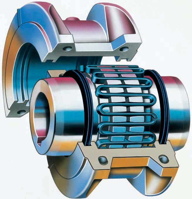
2 Falk Steelflex The simplest, most cost-effective coupling The Falk name is synonymous with grid couplings, as well as using shot peening to increase fatique strength and torque ratings. Steelflex redefines total coupling value up to 7.5 million in-lb, Nm torque. Steelflex offers simpler initial installation than gear couplings, and our new HD design outlasts competitive gear couplings to 1. The unique replace in place design eliminates the need to move hubs or re-align shafts, reducing element change-out time. When you look (see chart below) at the overall savings in initial costs, spare parts costs, and labor costs for installation, alignment and replacement - plus improved ratings and a 5 Year Heavy-Duty Warranty - it s easy to see what Steelflex Grid Couplings have over the competition. No other coupling in the torque range can touch Steelflex for cost-effective performance and reliability. ELASTOMER DISC GEAR STEELFLEX Coupling Lifetime Operating Costs 150 HP (11 RPM $,95 Total $,90 Total $5, Total $7,717 Total I I I I I I I I I 0 1,000,000,000,000 5,000,000 7,000,000 U.S. Suggested Consumer Production losses are not included in this chart. Initial Costs Labor Costs to Install & Align Spare Parts Costs Replacement Labor Costs Features That Give Steelflex the Lowest Lifetime Operating Cost Longer Life Tapered grids, made of high strength alloy steel, are quenched and tempered to spring hardness. The grid surface is then precision shot peened to compress the surface molecules. The effect is a dramatic increase in rating, providing reserve strength for longer life or allowing a smaller size coupling to be selected. This precision technology was originally used in the production of sophisticated aircraft components. Extended Maintenance Periods Now you can install Steelflex and lubricate it with Falk Long Term Grease (LTG) and forget periodic, routine maintenance for five years. Falk LTG grease was developed specifically for couplings. It resists the separation of the oil and thickening agent that occurs in typical greases. The initial use of Falk LTG coupling grease will eliminate routine lubrication cycles while still providing the necessary lubrication to the tapered grid. With LTG, Steellflex combines the high torque performance of a gear coupling and the low maintenance of a disc or elastomer coupling. Type HD Couplings The Preferred Replacement for Gear Couplings Durable Nitrile Seals are heat resistant to 75 ο F. (15 ο C.) Powder-coated covers provide chemical resistance.

3 Quick, Easy Installation Replace-In-Place Design The grid is the wearing member of a Steelflex coupling and it is a fraction of the complete coupling cost. Tapered grids are accessible through the quickly removable cover. The replace-in-place design of the replacement grids allows them to be dropped in without the need to remove or reposition hubs or realign shafts as required with gear couplings and many elastomer designs When coupling-connected equipment must be moved, the job takes longer and costs a lot more. Equipment Protection Against Shaft Misalignment The grid is free to rock, pivot and float within the hub teeth. Generous misalignment capacity is provided without producing detrimental bearing side loads created by other couplings. Equipment Protection Against Shock/Vibratory Loads Torsional flexibility is the ability of Falk Steelflex couplings to torsionally deflect LIGHT LOAD when subjected to normal shock or vibratory loads, providing flexible accommodation HEAVY LOAD to changing load conditions. Consequently, Steelflex tunes the drive system. It absorbs impact energy by spreading it over an increment of time. It damps vibration and reduces peak or shock loads by as much as 0%. It is a true shock absorber for rotary motion, relying on the predictable resilience of the steel grid for torsional flexibility. CONTACT INCREASES Steelflex HD Grid Couplings The preferred replacement for gear couplings LOW CONTACT PIVOTS FLOATS ROCKS Versatile Designs Two cover designs are available in the popular sizes. Standard spacer, piloted, high speed, brakewheel or disc, and controlled torque designs are also available. Worldwide Availability Steelflex couplings and component parts, are available in popular sizes and types. Our distribution centers and worldwide distribution network offer the largest stock of rough bore, finish straight bore and Taperlock bushed hubs of any shaft coupling on the market. Plus, Steelflex grid couplings are warranted for 5 Years when lubricated with Falk LTG Long Term Grease.
4 Steelflex Selection Guide
5 Selection Guide M1-110, February 007 Table of Contents How to Select, Standard & Formula Methods Quick selection Method Service Factors How to Order T Type Steelflex Grid Couplings: Dimensions & Specifications Type T10 Close Coupled Type T0 Close Coupled Type T1 Full Spacer Type T5 Half Spacer Type T1 & LT Controlled Torque Coupling Type T Controlled Torque Clutches Type T5 & T Piloted Controlled Torque Assemblies.... Optional Automatic Proximity Sensor Cutout Switch..... Slip Torque Performance Charts Type T50 Floating Shaft Assembly Type T50 Floating Shaft Selections Type T Disc Brake Type T70 High Speed Type T90 Flywheel Type T10/G Spacer Engineering Data Recommended Commercial Keys Metric and Inch..... Shaft Diameters & Ratings for 50 Hertz Metric Motors & NEMA 0 Hertz Ranges With Square & Rectangular Keys Taper Lock Bushings for Type T Hubs & Shaft Hubs WR Values Misalignment Capacities Standard AISE AC & DC Mill Motor Coupling Selections... 1 Taper and Counter Limitations Puller Bolt Holes Recommended s Metric and Inch Coupling Application Data Sheet Factory Warranty We re so confident in the performance and reliability of our latest generation of Falk gear drives that we re backing this comprehensive offering with the best standard warranty in the business. Our full, -year Heavy-Duty Warranty provides shaft-to-shaft protection on all Falk components including bearings and seals. It s an industry first... and one more powerful reason why Rexnord is your ultimate bottom-line drive and coupling value. Steelflex grid couplings are warranted for 5 years when lubricated with Falk LTG Long Term Grease. All Falk Steelflex Couplings Possess the Following Benefits High Ratings Extended Maintenance Periods Quick Installation Easy Maintenance Versatile Design Availability Protection Against Shaft Misalignment Protection Against Shock Loads, Vibration and Thrust Loads General Information Rexnord standards apply unless otherwise specified. All Dimensions are for reference only and are subject to change without notice unless certified. Unless otherwise specified, Falk coupling hubs Sizes 100T thru 1090T will be bored for CLEARANCE FIT with a setscrew OVER the keyway, and Sizes 1100T and larger will be furnished for INTERFERENCE FIT without a setscrew (see Table 7, Page ). Recommended key sizes for the listed maximum bores are shown in Table 1 on Page. Torque ratings of couplings utilizing Taper-Lock bushings can differ from those that do not. Refer to the Factory for details. If Rexnord is to supply coupling hubs bored for Taper-Lock bushings, the bushing manufacturer MUST be noted on the order. Consult the Factory when limited end float is required. Reference Notes Peak torque capacity is two times the published rating. Torque ratings for hubs with bushings differ from those shown, refer to Table 19, Page 9. Consult the Factory for higher speeds. imum bores are reduced for hubs furnished with an INTERFERENCE FIT and a setscrew OVER the keyway. Refer to Rexnord Engineering Sheet for details. imum bore is the smallest bore to which a RSB hub (rough stock bore) hub can be bored. Depending upon coupling size, rough stock bore hubs may have only a blind centering hole or a through hole that will permit remachining of the hubs to the minimum bores specified. Warranty extends for years from date of shipment. Copyright 00, 007. Rexnord Industries, LLC. All Rights Reserved. Litho in U.S.A. Steelflex and Rexnord are registered trademarks of Rexnord Industries, LLC. Falk is a trademark of Rexnord. Dodge is a registered trademark. Taper-Lock is a registered trademark of a bushing under license. The contents of this selection guide are subject to change without notice or obligation. Information contained herein should be confirmed before placing orders. Rexnord Industries, LLC, 00, 007 (M1-110) 5
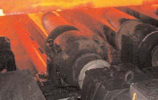
6 Falk Steelflex Grid Couplings A general purpose, lubricated design that combines the economy and high torque capacity of a gear coupling with the torsional flexibility of an elastomer coupling. Backed by a 5 year lubrication warranty, Falk Steelflex couplings require no periodic maintenance when lubricated with Falk LTG (Long Term Grease) at installation. Featuring 5 sizes, Stelflex couplings can accommodate torque loads of (Nm) and shaft diameters of 50 millimeters. A double flexing, close-coupled design for use in four bearing systems. Features a horizontally split cover which allows for grid replacement without the movement of the connected equipment. (See Page 1.) Type T10 Close Coupled Type T50 Piloted For use on line shaft applications. Can be used in place of single engagement gear couplings to provide torsional resiliency and lower overall operating cost. (See Pages & 9.) A double flexing design featuring a vertically split steel cover. Ideal for higher running speeds. (See Page 15.) Proven to be far superior to drum-type brakes in cost, construction and performance. (See Pages 0 thru.) Type T0 Close Coupled Type T Disc Brake Complete center section drops out for easy service of connected equipment bearings and seals. Ideal for pump applications. (See Pages 1 & 17.) Designed for operating speeds beyond those of the T10 and T0 designs. Features a one-piece cover and balanced components. (See Page.) Type T1 Full Spacer Type T70 High Speed An economical spacer design for easy service of connected equipment bearings and seals. Ideal for pump applications. (See Pages 1 & 19.) Used primarily to connect the flywheel of an engine to the driven machinery. It provides for higher torque ratings with resulting smaller sizes and lower costs than elastomer couplings. (See Page.) Type T5 Half Spacer Type T90 Flywheel Provides adjustable slipping action to protect connected equipment from shock, jams, or temporary overloads. (See Pages 0 thru 7.) Type T1, T, T & T5 Controlled Torque Type T10/G Spacer A combination of two standard Falk couplings. Utilizes readily available components for an economical price and shorter lead time than T1/T5 couplings. (See Page 5.) Type T50 Floating Shaft Double piloted design for connecting equipment where the distance between shafts is too large for a spacer type coupling. (See Pages & 9.) Type BW Brakewheel Provides a built-in braking surface right at or near the centerline of the coupling...saves space and dollars. (See Selection Guide 1-10.) WARNING! Mixing grid coupling components from different manufacturers may cause premature failure and possible personal injury or property damage from flying debris. (M1-110) Rexnord Industries, LLC, 00, 007
7 How to Select Standard Selection Method (except T1/T &T) The standard selection method can be used for most motor, turbine, or engine driven applications. The following information is required to select a flexible coupling: Kilowatt (kw) or torque Running rpm Application or type of equipment to be connected (motor to pump, gear drive to conveyor, etc.) Shaft diameters Shaft gaps Physical space limitations Special bore or finish information and type of fit Exceptions are High Peak Loads and Brake Applications. For these conditions use the Formula Selection Method in the next column, or consult your local Falk Representative for assistance. 1. RATING: Determine system torque. If torque is not given, calculate as shown below: kw x 959 System Torque (Nm) = rpm Where kilowatt (kw) is the actual or transmitted power required by the application (if unknown, use the motor or turbine nameplate rating) and rpm is the actual speed the coupling is rotating. Applications that require rapid changes in direction or torque reversals should be referred to Rexnord Engineering.. SERVICE FACTOR: Determine appropriate service factor from Table, Page 1.. REQUIRED MINIMUM COUPLING RATING: Determine the required minimum coupling rating as shown below: imum Coupling Rating = S.F. (Service Factor) x Torque (Nm). TYPE: Refer to Page and select the appropriate coupling type. 5. : Turn to appropriate pages for the coupling type chosen and trace down the torque column to a value that is equal or greater than that determined in Step above. The coupling size is shown in the first column.. CHECK: Check speed (rpm), bore, gap, and dimensions. STANDARD SELECTION EXAMPLE: Select a coupling to connect a 55 kw, 1500 rpm electric motor driving a lobe type blower. Motor shaft diameter is 0 mm, blower shaft diameter is 5 mm. Shaft extensions are 10 mm and 110 mm. Selection is replacing a gear type coupling with a mm gap. 1. DETERMINE REQUIRED RATING: 55 kw x 959 System Torque (Nm) = = 50 Nm 1500 rpm. SERVICE FACTOR: From Table = 1.5. REQUIRED MINIMUM COUPLING RATING: 1.5 x 50 Nm = Nm. : From Page 1 a Size 1070T is the proper selection based on a torque rating of 90 Nm exceeding the required minimum coupling rating of Nm. 5. CHECK: Allowable speed capacity of 15 (1070T10) exceeds the required speed of 1500 rpm. imum bore capacity of 7 mm exceeds the actual shaft diameters. Type T Static (holding) Brake Applications 1. : The brake rating must equal or exceed the application requirements. Determine the required coupling size by comparing the application loads (from Steps A and B below) to the coupling brake rating listed on Page 1. Use the highest torque value calculated to determine the coupling size. A. For normal service applications, use the application torque in Nm. Transmitted kw x 959 System Torque (Nm) = rpm B. For repetitive high peak load applications, use the system peak torque in Nm. (Repetitive is defined as more than 1000 times during the expected coupling life.). CALIPER TORQUE BRAKE RATING: For the coupling size selected, compare the caliper brake torque rating on Page 1 to the holding torque requirement of the application. Rexnord recommends that the caliper torque rating (min.) be at least two times the holding torque requirement for static applications to compensate for the possibility of foreign matter on the disc surfaces, loss of condition of the brake pad surfaces, or other conditions that may affect the holding ability of the caliper brake. Caliper brakes and brake discs listed are designed primarily for static and/or emergency brake applications. NOTE: Check brake system and lining wear after emergency stops. They can, however, also be used for dynamic stopping if only used occasionally, such as shutting down the equipment for the day or between shift changes. For stopping high inertia systems or for applications that require more frequent stopping, consult your local Rexnord Representative.. CHECK: Check maximum bores, speeds, and dimensions. Type T Stopping Or Service Brake Applications 1. : The coupling brake rating must equal or exceed the application requirements. Determine the required coupling size by comparing the application loads (from Steps A, B and C below) to the coupling brake rating listed on Page. Use the highest torque value calculated to determine the coupling size. A. For the selected caliper brake and disc diameter,use the maximum brake torque in Nm. B. For normal service applications, use the application torque in Nm. Transmitted kw x 959 System Torque (Nm) = rpm C. For repetitive high peak load applications, use the system peak torque in Nm (Repetitive is defined as more than 1000 times during the expected coupling life.). CHECK: Check maximum bores, speeds, and dimensions. Rexnord Industries, LLC, 00, 007 (M1-110) 7
8 How to Select Formula Selection Method (except T1/T & T) The Standard Selection Method can be used for most coupling selections. The procedures below should be used for: High Peak Loads. Brake Applications (where the brake disc or brake wheel is to be an integral part of the coupling, consult the Factory for design options). Providing system peak torque and frequency, duty cycle, and brake torque rating will allow for a more refined selection using the Formula Selection Method. 1. HIGH PEAK LOADS: Use one of the following formulas for applications using motors with torque characteristics that are higher than normal; applications with intermittent operations, shock loading, inertia effects due to starting and stopping and or system induced repetitive high peak torques. System Peak Torque is the maximum torque that can exist in the system. Select a coupling with a torque rating equal to or greater than selection torque calculated below. A. NON-REVERSING HIGH PEAK TORQUE Selection Torque (Nm) = System Peak Torque or System Peak kw x 959 Selection Torque (Nm) = rpm B. REVERSING HIGH PEAK TORQUE Selection Torque (Nm) =xsystem Peak Torque or x Peak kw x 959 Selection Torque (Nm) = rpm C. OCCASIONAL PEAK TORQUES (Non-Reversing) If a system peak torque occurs less than 1000 times during the expected coupling life, use the following formula: Selection Torque (Nm) = 0,5 x System Peak Torque or 0,5 x Peak kw x 959 Selection Torque (Nm) = rpm For reversing service select per step B.. BRAKE APPLICATIONS: If the torque rating of the brake exceeds the motor torque use the brake rating as follows: Selection Torque (Nm) = Brake Torque Rating x S.F. FORMULA SELECTION EXAMPLE High Peak Load: Select a coupling for reversing service to connect a gear drive low speed shaft to a runout mill table roll. The electric motor rating is 7 kw at the base speed and the system peak torque at the coupling is estimated to be Nm. Coupling speed is 77 rpm at the motor base speed. The drive shaft diameter is 100 mm with a key of mm x 1 mm. The runout table roll diameter is 15 mm with a key of mm x 0 mm. imum shaft gap (BE) is 10 mm long. 1. TYPE: Refer to Page and select the appropriate coupling type.. REQUIRED MINIMUM COUPLING RATING: Use the Reversing High Peak Torque formula in Step 1B. x = 000 = Selection Torque. : From Page 19, Size 1150T5 with a torque rating of 9 00 exceeds the selection torque of 000 Nm.. CHECK: The 1150T5 has a maximum BE dimension of 17,5 mm; the shaft hub has a maximum bore of 70 mm (Table 1, Page 7 ); the T hub has a maximum bore of 15 mm (Table 15, Page 7); and the allowable speed of 1500 rpm and the dimensions on Page 19 meet the requirements. TABLE 1 Coupling Ratings & Allowable Speeds Coupling Size kw/rpm Torque Rating (Nm) T10 Allowable Speeds rpm T0 & T50 T1, T5 & T10/G 100T 0, T 0, T 0, T 0, T 0, T 0, T 0, T 0, T 0, T 0, T 1, T, T, T, T 5, T 7, T 10, T 1, T 19, T T 5, T 5, T 5, T 7, T 97, Refer to Page 5 for General Information and Reference notes. kw/rpm and torque rating values for hubs with Taper Lock bushings differ from those shown above. Refer to Table 19, Page 9. Speeds shown above are for single Type T50 couplings; speeds for Type T50 Floating Shaft couplings are shown in Table 1, Page 9. T70 (M1-110) Rexnord Industries, LLC, 00, 007
9 How to Select Type T1 Controlled Torque Couplings & T Controlled Torque Clutches Type T1 Controlled Torque Couplings 1. RUNNING TORQUE: Calculate normal running torque Required kw x 959 Running Torque (Nm) = rpm. SLIP TORQUE: Slip torque = Running Torque x 150% (Overload Setting.) Rexnord recommends a minimum 150% overload setting for steady or moderate shock load applications. For heavy shock load applications, a 00% or greater overload setting may be required.. COUPLING : Refer to Table, Page 0 Trace down the Slip Torque column to a figure equal to or in excess of the calculated slip torque determined in Step. Read the coupling size in the next column.. CHECK: A. Check shaft diameters against coupling maximum bores shown in Table, Page 0. If selection does not have adequate bore capacity, refer to Table 15, Page 7 or Table 17, Page for maximum bores with square or rectangular keys, or select the next larger size coupling. B. Check the required speed against the allowable speed shown in Table, Page 0. If a higher speed is required, refer application details to the local Rexnord representative. C. Check allowable slip torque times from Slip Torque Performance Charts on Pages through 7. The length of time a coupling can slip without exceeding its thermal capacity is a function of the slip torque setting and the operating speed. An automatic cutout switch, Page, can be provided when damaging thermal conditions exist. D. Check application dimension requirements against selected coupling dimensions shown on Page 0. E. Check usable shaft length to the coupling hub lengths on Page 1. If necessary, overhang hubs within the limits specified on Page. SELECTION EXAMPLE: Select a controlled torque coupling to connect a 15,0 kw, 1500 rpm, 10L frame motor to the high speed shaft of a gear drive driving a screw feeder. Motor shaft diameter is mm with a usable shaft length of 110 mm. Drive high speed shaft diameter is 5 mm with usable shaft length of 5 mm. 1. RUNNING TORQUE: From Step 1 above: 15,0 kw x 959 Running Torque (Nm) = = 95,5 Nm 1500 RPM. SLIP TORQUE: From Step above: Slip Torque = 95,5 Nm x 150% = 1, Nm.. : From Table, Page 0, the minimum size coupling is the Size 0T1, which has a maximum slip torque of 17 Nm.. CHECK: A. From Table, Page 0, the Size 0T1, T1 hub has a maximum bore capacity of only 5 mm and the T hub maximum bore capacity is mm. The preferred mounting arrangement is to have the T1 hub on the motor (for optimum cooling during slippage). Therefore, select the size 50T1 with a T1 hub maximum bore capacity of 5 mm, as compared to the motor shaft diameter of mm, and the slip torque required is within its range. B. Allowable Speed of 00 rpm exceeds required 1500 rpm. C. From Page, the Size 50T1 with slip torque setting of 1, Nm and running speed of 1500 rpm will permit 7 seconds slip if followed by 9 minutes of non-slip. D. See Page 0 for dimensions. E. Usable shaft length of motor is 110 mm and W dimension for T1 hub is 7, mm, therefore no overhang required. Usable shaft length of drive is 5 mm and C dimension of T hub is 0,5 mm, therefore no overhang required. Type T Controlled Torque Clutches 1. RUNNING TORQUE Required kw x 959 Running Torque (Nm) = rpm. SLIP TORQUE: Slip Torque = Running Torque x 150% (Overload Setting.) Rexnord recommends a minimum 150% overload setting for steady or moderate shock load applications. For heavy shock load applications a 00% or greater overload setting may be required.. CLUTCH : Refer to Table 9, Page 1 Trace down the Slip Torque column to a figure equal to or in excess of the calculated slip torque determined in Step. Read clutch size in the next column. A. Check shaft diameters against clutch maximum bores shown in Table 9. If selection does not have adequate bore capacity refer to Table 17, Page for maximum bores with square or rectangular keys, or select the next larger size clutch. B. Check the required speed against the allowable speed shown in Table 9. If a higher speed is required, refer application details to the local Rexnord representative. C. Check allowable slip torque times from Slip Torque Performance Charts on Pages through 7. The length of time a clutch can slip without exceeding its thermal capacity is a function of the slip torque setting and the operating speed. An automatic cutout switch, Page, can be provided when damaging thermal conditions exist. D. Check application dimension requirements against selected clutch dimensions shown on Page 1. E. Check usable shaft length to the clutch hub length on Page 19. If necessary, overhang hub within the limits specified on Page. Rexnord Industries, LLC, 00, 007 (M1-110) 9
10 Quick Selection Method 1. Select Coupling Type Refer to Page and select the type of coupling to suit your application. If an application requires a special purpose coupling, refer application details to the local Rexnord Representative.. Determine Service Factor. A. For MOTOR, TURBINE or ENGINE driven applications, refer to Tables and 5. B. For BRAKE or HIGH PEAK LOAD applications, refer to the Formula Selection Method shown on Page.. Determine Equivalent Power. RefertoTable Under the actual kw required and opposite the service factor determined in Step, read the equivalent kw.. Determine Coupling Size. A. Refer to Table Trace horizontally from the required speed to a hp value equal to or larger than the equivalent kilowatts determined in Step. Read the coupling size at top of column. TABLE Equivalent Power = (Actual kw x Service Factor) Service Factor Actual kw For service factors not listed. Equivalent kw = Actual kw x Service Factor. TABLE CouplingSelection...BasedonEquivalent kw Ratings (mm) Speed T10 Speed T0 Torque (Nm) kw / rpm RPM 100T 100T 100T 1050T 100T 1070T 100T 1090T 1000T 1100T 110T 110T 500 rpm 000 rpm 5 0, rpm 000 rpm 19 0., rpm 000 rpm 9 0, rpm 000 rpm 5 0, rpm 000 rpm 5 0, rpm 5500 rpm 995 0,10 kw Ratings 0 00 rpm 750 rpm 050 0, rpm 000 rpm 70 0, rpm 50 rpm 75 0, rpm 000 rpm 90 0, rpm 700 rpm 170 1, rpm 00 rpm 195, T0 Only. 10 (M1-110) Rexnord Industries, LLC, 00, 007
11 B. Check shaft diameters against coupling maximum bores shown in Tables 15 thru 1 for the type of coupling selected. If a larger bore is required, select a larger coupling. C. Check the required speed against the allowable speed shown in Table 1 for the type of coupling selected. For Type T50 Floating Shaft design, check the allowable speed from Table 1 on Page 9. If a higher speed is required, refer application details to the local Rexnord Representative. D. Check application dimension requirements against selected coupling type dimensions shown on Pages 1 thru 5. Example: Select a Steelflex coupling to connect the low speed shaft of a gear drive to a belt conveyor. The motor is 50 kw and the low speed shaft RPM is. The gear drive shaft is 10 mm and the conveyor shaft is 10 mm. 1. Select Coupling Type To connect close coupled shafts, and to accommodate anticipated shaft misalignment, the double engagement Type T10 coupling shown on Page 1, is the selection.. Determine Service Factor From Table, Page 1, the service factor is Determine Equivalent HP From Table, Page 10, the equivalent power is 50 kw.. Select coupling Size (A) From Table, Page 11, the coupling size is 1150T10 for RPM. (B) From Table, the maximum bore of 15 mm, and allowable speed of 1500 rpm are all satisfactory. Check other dimensional information on Page 1 against the available shaft lengths, shaft gaps, and diameter restrictions. TABLE CouplingSelection...BasedonEquivalent kw Ratings (Continued) (mm) Speed T10 Speed T0 Torque (Nm) kw / rpm RPM 110T 1150T 110T 1170T 110T 1190T 100T 110T 10T 10T 10T 150T rpm 00 rpm 55, rpm 000 rpm 9770, rpm 100 rpm , 0 15 rpm 100 rpm , rpm , rpm , rpm ,5 kw Ratings 90 0 rpm rpm , rpm , 0 0 rpm , 50 rpm , Refer to Falk. T0 Only. 50 rpm , Rexnord Industries, LLC, 00, 007 (M1-110) 11
12 Service Factors TABLE FlexibleCouplingServiceFactors for Motor and Turbine Drives Service factors listed are typical values based on normal operation of the drive systems. Alphabetical listing of applications Alphabetical listing of industries Service Factor AERATOR...0 AGITATORS Vertical and Horizontal Screw, Propeller, Paddle BARGE HAUL PULLER BLOWERS Centrifugal Lobe or Vane CAR DUMPERS...5 CAR PULLERS CLARIFIER OR CLASSIFIER COMPRESSORS Centrifugal Rotary, Lobe or Vane Rotary, Screw Reciprocating Direct Connected...Refer to Factory Without Flywheel...Refer to Factory With Flywheel and Gear between Compressor and Prime Mover 1 cylinder, single acting cylinder, double acting...0 cylinders, single acting...0 cylinders, double acting...0 cylinders, single acting...0 cylinders, double acting...0 or more cly., single act or more cyl., double act CONVEYORS Apron, Assembly, Belt, Chain, Flight, Screw Bucket Live Roll, Shaker and Reciprocating...0 s CRANES AND HOIST Main Hoist Skip Hoist Slope Bridge, Travel or Trolley DYNAMOMETER ELEVATORS Bucket, Centrifugal Discharge Freight or Passenger...Not Approved Gravity Discharge ESCALATORS... Not Approved EXCITER, GENERATOR EXTRUDER, PLASTIC FANS Centrifugal Cooling Tower...0 Forced Draft Across the Line start Forced Draft Motor Driven thru fluid or electric slip clutch Gas Recirculating Induced Draft with damper control or blade cleaner Induced Draft without controls...0 FEEDERS Apron, Belt, Disc, Screw Reciprocating...5 GENERATORS Even Load Hoist or Railway Service Service Factor Welder Load...0 HAMMERMILL LAUNDRY WASHER OR TUMBLER...0 LINE SHAFTS Any Processing Machinery MACHINE TOOLS Auxiliary and Traverse Drive Bending Roll, Notching Press, Punch Press, Planer, Plate Reversing Main Drive MAN LIFTS... Not Approved METAL FORMING MACHINES Continuous Caster Draw Bench Carriage and Main Drive...0 Extruder...0 Farming Machine and Forming Mills...0 Slitters Wire Drawing or Flattening Wire Winder Coilers and Uncoilers MIXERS (see Agitators) Concrete Muller PRESS, PRINTING PUG MILL PULVERIZERS Hammermill and Hog Roller PUMPS Boiler Feed Centrifugal Constant Speed Frequent Speed Changes under Load Descaling, with accumulators Gear, Rotary, or Vane Reciprocating, Plunger Piston 1 cyl., single or double act...0 cyl., single acting...0 cyl., double acting or more cylinders Screw Pump, Progressing Cavity Vacuum Pump SCREENS Air Washing Grizzly...0 Rotary Coal or Sand Vibrating...5 Water SKI TOWS & LIFTS...Not Approved STEERING GEAR STOKER TIRE SHREDDER TUMBLING BARREL WINCH, MANEUVERING Dredge, Marine WINDLASS WOODWORKING MACHINERY WORK LIFT PLATFORMS...Not Approved For engine drives, refer to Table 5. Electric motors, generators, engines, compressors and other machines fitted with sleeves or straight roller bearings usually require limited end float couplings. If in doubt, provide axial clearances and centering forces to the Factory for a recommendation. For balanced opposed design, refer to the Factory. If people are occasionally transported, refer to the Factory for the selection of the proper size coupling. For high peak load applications (such as Metal Rolling Mills) refer to the Factory. TABLE 5 Engine Drive Service Factors Service Factors for engine drives are those required for applications where good flywheel regulation prevents torque fluctuations greater than ±0%. For drives where torque fluctuations are greater or where the operation is near a serious critical or torsional vibration, a mass elastic study is necessary. No. of Cylinders or 5 or more Table S.F Engine S.F To use Table 5, first determine application service factor from Table. Use that factor to determine ENGINE Service Factor from Table 5. When service factor from Table is greater than.0, or where 1,, or cylinder engines are involved, refer complete application details to Rexnord Engineering. Service Factor AGGREGATE PROCESSING, CEMENT, MINING KILNS; TUBE, ROD AND BALL MILLS Direct or on L.S. shaft of Reducer, with final drive Machined Spur Gears...0 Single Helical or Herringbone Gears Conveyors, Feeders, Screens, Elevators...See General Listing Crushers, Ore or Stone...5 Dryer, Rotary Grizzly...0 Hammermill or Hog Tumbling Mill or Barrel BREWING AND DISTILLING Bottle and Can Filling Machines Brew Kettle Cookers, Continuous Duty Lauter Tub Mash Tub Scale Hopper, Frequent Peaks CLAY WORKING INDUSTRY Brick Press, Briquette Machine, Clay Working Machine, Pug Mill DREDGES Cable Reel Conveyors Cutter head, Jig Drive...0 Maneuvering Winch Pumps (uniform load) Screen Drive, Stacker Utility Winch FOOD INDUSTRY Beet Slicer Bottling, Can Filling Machine Cereal Cooker Dough Mixer, Meat Grinder LUMBER Band Resaw Circular Resaw, Cut-off Edger, Head Rig, Hog...0 Gang Saw (Reciprocating)...Refer to Factory Log Haul...0 Planer Rolls, Non-Reversing Rolls, Reversing...0 Sawdust Conveyor Slab Conveyor Sorting Table Trimmer METAL ROLLING MILLS Coilers (Up or Down) Cold Mills only Coilers (Up or Down) Hot Mills only...0 Coke Plants Pusher Ram Drive...5 Door Opener...0 Pusher or Larry Car Traction Drive...0 Continuous Caster Cold Mills Strip Mills...Refer to Factory Temper Mills...Refer to Factory Cooling Beds Drawbench...0 Feed Rolls - Blooming Mills...0 Furnace Pushers...0 Hot and Cold Saws...0 Hot Mills Strip or Sheet Mills...Refer to Factory Reversing Blooming...Refer to Factory or Slabbing Mills...Refer to Factory Edger Drives...Refer to Factory Ingot Cars...0 Manipulators...0 Merchant Mills...Refer to Factory Mill Tables Roughing Breakdown Mills...0 Hot Bed or Transfer, non-reversing Runout, reversing...0 Runout, non-reversing, non-plugging...0 Reel Drives Rod Mills...Refer to Factory Screwdown...0 Seamless Tube Mills Piercer...0 Thrust Block...0 Tube Conveyor Rolls...0 Reeler...0 Kick Out...0 Shear, Croppers...Refer to Factory Sideguards...0 Skelp Mills...Refer to Factory Service Factor Slitters, Steel Mill only Soaking Pit Cover Drives Lift Travel...0 Straighteners...0 Unscramblers (Billet Bundle Busters)...0 Wire Drawing Machinery OIL INDUSTRY Chiller Oil well Pumping (not over 150% peak torque)...0 Paraffin Filter Press Rotary Kiln...0 PAPER MILLS Barker Auxiliary, Hydraulic...0 Barker, Mechanical...0 Barking Drum L.S. shaft of reducer with final drive - Helical or Herringbone Gear...0 Machined Spur Gear...5 Cast Tooth Spur Gear...0 Beater & Pulper Bleachers, Coaters Calender & Super Calender Chipper...5 Converting Machine Couch Cutter, Felt Whipper...0 Cylinder Dryer Felt Stretcher Fourdrinier Jordan...0 Log Haul...0 Line Shaft Press Pulp Grinder Reel, Rewinder, Winder Stock Chest, Washer, Thickener Stock Pumps, Centrifugal Constant Speed Frequent Speed Changes Under Load Suction Roll Vacuum Pumps 1.5 RUBBER INDUSTRY Calender...0 Cracker, Plasticator...5 Extruder Intensive or Banbury Mixer...5 Mixing Mill, Refiner or Sheeter One or two in line...5 Three or four in line...0 Five or more in line Tire Building Machine...5 Tire & Tube Press Opener (Peak Torque) Tuber, Strainer, Pelletizer Warming Mill One or two Mills in line...0 Three or more Mills in line Washer...5 SEWAGE DISPOSAL EQUIPMENT Bar Screen, Chemical Feeders, Collectors, Dewatering Screen, Grit Collector SUGAR INDUSTRY Cane Carrier & Leveler Cane Knife & Crusher...0 Mill Stands, Turbine Driver With all helical or Herringbone gears Electric Drive or Steam Engine Drive with Helical, Herringbone, or Spur Gears with any Prime Mover TEXTILE INDUSTRY Batcher Calender, Card Machine Cloth Finishing Machine Dry Can, Loom Dyeing Machinery Knitting Machine...Refer to Factory Mangle, Napper, Soaper Spinner, Tenter Frame, Winder (M1-110) Rexnord Industries, LLC, 00, 007
13 SERVICE FACTORS are a guide, based on experience, of the ratio between coupling catalog rating and system characteristics. The system characteristics are best measured with a torque meter. Torque Demands Driven Machine Typical applications for electric motor or turbine driven equipment Constant Torque such as Centrifugal Pumps, Blowers, and Compressors. Continuous duty with some torque variations including Plastic Extruders, Forced Draft Fans. Light shock loads from Metal Extruders, Cooling Towers, Cane Knife, Log Haul. Moderate shock loading as expected from a Car Dumper, Stone Crusher, Vibrating Screen. Heavy shock load with some negative torques from Roughing Mills, Reciprocating Pumps, Compressors, Reversing Runout Tables, Applications like Reciprocating Compressors with frequent torque reversals, which do not necessarily cause reverse rotations. Typical Service Factor Consult Rexnord Engineering How to Order The following information is necessary to quote or ship to your exact requirements. Prompt service is assured if this information is given on your inquiry or order. 1. Application: Driver & Driven. Power: Normal kw, imum kw or Torque (Nm). Speed (RPM). For Type T Disc Brake Couplings, furnish brake requirements. A. Holding torque requirement. B. WR of rotating parts (at brake location.) C. Frequency of stops. D. Rate of deceleration required desired stop time and stopping rpm. 5. Quantity. Coupling Size and Type e.g., 110T1 or 1070T10 7. Shaft Gap or distance between shaft ends (BE Dimension). Sizes: Must Specify clearance or interference fit, or fit will be furnished per Table 7, Page. sizes will be furnished as per Tables 9 or 0 on Pages -5 unless specified differently. 9. Shaft Dimensions as follows: For Straight Shafts: Driving Shaft Driven Shaft Diameter U Diameter U Tolerance Tolerance Y V W Length V Length V V X Keyway Keyway U IF MACHINES ARE IN PLACE FURNISH GAP DIMENSION. GAP ZW U TAPER PER LENGTH ON DIAMETER NOTE: Provide shaft tolerances if different than those shown in Tables thru 0, Pages -5. Unless otherwise specified, metric keyways will be furnished per ISO/R and J S 9 width tolerances. Keyway sizes in inch shafts will be furnished based on key sizes listed in Table 1, Page, to Rexnord tolerances. For other shaft/bore requirements, consult Factory. For Taper Shafts: keyway is assumed to be parallel to the bore. Diameter U Across Flats Length V Corners ZW Length W Taper Length X Keyway Length Y Rexnord Industries, LLC, 00, 007 (M1-110) 1
14 Type T10 Close Coupled/Dimensions Millimeters COVER PROFILES HORIZONTAL SPLIT GRID HUB S A S F A J A D C S GAP C S F A S A Sizes 100 thru 10T10 covers are cast aluminum alloy; Sizes 10 thru 10T10 are fabricated steel. LUBE PLUGS J Type HD size range is from as shown in screens below. Covers are powder-coated and seals are Nitrile. B Torque Rating Nm Allow Speed rpm mm mm Cplg Wt With No -kg Lube Wt kg DIMENSIONS MILLIMETERS A B C D F J S Gap 100T ,9 0,07 97,0 9, 7, 9,7...,7 9,1 100T ,5 0,00 105,7 9, 7, 9,..., 9,1 100T , 0,05 11, 10, 50, 57,... 9,9 0,1 1050T , 0,00 15,1 1, 0,,7... 0,9,7 100T , 0,0 17, 10,0,5 7,... 9,5 5, 1070T , 0,11 15, 155, 7, 7,... 9, 5, 100T ,9 0,17 190,5 10,,9 10, ,,5 1090T , 0,5 11,1 199, 9, 1,... 1, 71, 1100T ,0 0, 51,0, 10, 1, , T , 0,50 9,7 59,0 17,0 10,... 11, T , 0,75 07, 0, 19, 179, , T ,907 5,9 9, 11,9 17, , T ,1,0 7, 1, 5, , T ,95 5,1 71, 1,9 9, 91, 71, T ,1 501,9 0, 19,1 0,,9 7, T ,9 5,9 7, 15,9 55, 7, 07, T ,7 9,9,, 9,7 55,7 1, T ,0 75, 5, 59,1,9 07, 5, T , 75,9 5, 79, 97, 0, 55, T ,5,, 0, 5, 750, 1, T ,1 90,, 5,1 571,5, 90, T ,0 1 00, 70, 5, 09, 90,7 5, T , 1 07,1 79,, 7,7... 7, T ,1 1 11,1 15, 01, 711,... 9, T , 1 0,9 7, 1, 7,0... 7, Refer to Page 5 for General Information and Reference Notes. Refer to the Factory. 1 (M1-110) Rexnord Industries, LLC, 00, 007
15 Type T0 Close Coupled/Dimensions Millimeters VERTICAL SPLIT COVER M LUBE PLUGS M GRID CLEARANCE FOR GRID REMOVAL HUB A F D C S GAP C H J B H J Torque Rating Nm Allow Speed rpm mm mm Cplg Wt Without -kg Lube Wt kg DIMENSIONS MILLIMETERS A B C D F H J M S Gap 100T ,9 0,07 11, 9,,7 9,7, 9,7,9 7, 9,1 100T ,5 0,00 11, 9,,7 9, 7, 9,7,9 7, 9,1 100T ,5 0,05 19, 10, 50, 57, 1, 9,7 5,9 50, 0,1 1050T , 0,00 1, 1, 0,,7 97, 11,9 0,5 0,5,7 100T ,01 0,0 1,1 10,0,5 7, 111,1 1,7 1,,5 5, 1070T , 0,11 17, 155, 7, 7, 1, 1,7,5,5 5, 100T , 0,17 01, 10,,9 10, 19, 1,7,7,9,5 1090T , 0,5,9 199, 9, 1, 1, 1,7 7,0 95, 71, 1100T ,0 0, 7,9, 10, 1,1 19,0 15,7 59,7 10, T , 0,50,9 59,0 17,0 10, 1, 1,0,7 1, T , 0,75 0, 0, 19, 179, 5,5 17,5 7,7 1, T ,907 79,0 9, 11,9 17,5, 0, 7,9 1, T ,1 17,1 7, 1, 5,0 1,9 0, 7, 155, T ,95 7, 71, 1,9 9, 7, 19, 107, 0, T ,1 5, 0, 19,1 0,,9 0,0 115, 15, T ,9 5, 7, 15,9 55, 7,7 0,0 10,1,1... Refer to Page 5 for General Information and Reference Notes. Dimension H is to the end of the bolt on Sizes 1150 thru Bolts are not shrouded. Rexnord Industries, LLC, 00, 007 (M1-110) 15
16 Type T1 Full Spacer/Dimensions Millimeters GRID GAP COVER FLANGE FASTENERS U U A F B S E E S B DD BETWEEN BE SHAFT ENDS SHAFT HUB SHAFT HUB Torque Rating Nm Allow Speed rpm mm mm Cplg Wt With No & BE kg SPACER HUB Wt Added Per mm of Lube Wt BE Over kg imum A B LUBE PLUGS BE SPACER HUB DIMENSIONS MILLIMETERS DD E F S U Gap Flange Fasteners 100T ,5 0,010 0,07 97,0,9,9 0 5, 0, 5,7 7, 1, 5 Gr T ,1 0,01 0,00 105,7 1,,9 1 59,5 0, 9,7 1,5 1, 5 Gr T , 0,01 0,05 11, 5,0,9 1 7, 0, 11,7 7, 1, 5 Gr T , 0,0 0,00 15,1 0, 111,1 1 7, 0, 15, 0, 1, 5 Gr.1 100T ,5 0,07 0,0 17, 7,0 1, 0 10, 1, 1,5,, 5 Gr T , 0,0 0,11 15, 79, 17, ,5 1, 15,,7, 5 1 Gr T ,0 0,09 0,17 190,5,9 155,5 0 1, 1, 177, 9,, 5 1 Gr T ,1 0,10 0,5 11,1 101, 1,5 0 1,9 1, 09, 5,9, 5 1 Gr T , 0,1 0, 51,0 90, 0, 0 171, 1, 50,..., 1 Gr T ,1 0,50 9,7 10,1 09, 0 19, 1, 7,..., 1 Gr T ,0 0,75 07, 119,,1 0 5, 1, 19,1..., Gr T ,9 0,907 5,9 1, 57,1 0,1 1,,1..., Gr T ,0 1,1,0 15,,7 0,7 1, 5,..., Gr Refer to Page 5 for General Information and Reference Notes. No. per Flange & SAE Grade Dia Inches TABLE Type T1 Standard Stock Spacer Lengths (BE=Distance Between Shaft Ends) Between Shaft Ends Pump COUPLING Millimeters Inch Std 100T 100T 100T 1050T 100T 1070T 100T 1090T 1100T 1110T 9.5 ANSI X X X ISO X X X 10.5 MISC X X X 111. ANSI X X X X MISC X X X X ANSI X X X X X X 1 5. MISC X MISC... X X ISO X X X X X X 1 5. MISC... X X MISC... X X X MISC X X MISC... X X X X X 17.9 MISC X X X X X ANSI X X ISO X X... X X X ANSI... X X X X X X X 0.00 MISC X 1.59 MISC X 19. MISC X X. MISC X 9.75 ANSI X X X X X X ISO X X MISC X MISC X ANSI X X X X MISC X 1 (M1-110) Rexnord Industries, LLC, 00, 007
17 Type T1 Full Spacer/Dimensions Millimeters.1 REGISTER DETAIL S 1150, 110, 1170 FLANGE FASTENERS GRID COVER E REGISTER DETAIL S 110, 1190, 100 U U A F B E BE GAP GREASE RETAINERS BETWEEN SHAFT ENDS E B DD SHAFT HUB SHAFT HUB SPACER HUB LUBE PLUGS SPACER HUB G5 Rigid Hub Size Torque Rating Nm Allow Speed rpm mm mm Cplg Wt With No & BE kg Wt Added Per mm of BE Over imum Lube Wt kg A B DIMENSIONS MILLIMETERS BE DD E F U Gap Flange Fasteners No. per Flange & Dia SAE Inches Grade 1150T 1055G ,19 1,95 5,1 17,7,5 71,, 5,1 5, Gr T 100G ,5,1 501, 1, 55, 0,,0, 57, Gr T 1070G ,,9 5, 0,,,5,9, 57, Gr T 100G ,7,7 9,9,9 00,1 90,5 50, 5,1 590,, Gr T 1090G ,0,0 75, 75, 11, 50, 50,0 5,1 0,, Gr T 1100G ,5 5, 75,9 05,,5 57,5 50,,1 711, 9, Gr Refer to Page 5 for General Information and Reference Notes. Dimension DD is for an as-cast, unmachined surface for Sizes 110, 1190, and 100. Type T1 couplings shown use Type G5 gear coupling rigid hubs as the shaft hubs. Rexnord Industries, LLC, 00, 007 (M1-110) 17
18 Type T5 Half Spacer/Dimensions Millimeters FLANGE FASTENER GAP COVER GRID U A F DD B S E BE BETWEEN SHAFT ENDS S C D SHAFT HUB T HUB SPACER HUB LUBE PLUGS Torque Allow Rating Speed Nm rpm mm Shaft Hub T Hub mm Cplg Wt With No & BE kg Wt Added Per mm of Lube Wt BE Over kg imum A B BE DIMENSIONS MILLIMETERS C D DD E F Shaft Hub S T Hub U Flange Fasteners Gap No. Per Dia Flange Inches & Grade 100T ,9 0,010 0,07 97,0,9 5, 10 7, 9,7 5, 0, 5,7 7, 9,1 1, Gr T ,9 0,01 0,00 105,7 1, 5, 109 7, 9, 59,5 0, 9,7 1,5 9,1 1, Gr T , 0,01 0,05 11, 5,0 5, , 57, 7, 0, 11,7 7, 0,1 1, Gr T ,1 0,0 0,00 15,1 0, 5, 109 0,,7 7, 0, 15, 0,,7 1, Gr.1 100T ,9 0,07 0,0 17, 7,0 1,9 1,5 7, 10, 1, 1,5, 5,, Gr T , 0,0 0,11 15, 79,, 1 7, 7, 109,5 1, 15,,7 5,, 1 Gr T ,9 0,09 0,17 190,5,9 7, 0,9 10, 1, 1, 177, 9,,5, 1 Gr T , 0,10 0,5 11,1 101,, 0 9, 1, 1,9 1, 09, 5,9 71,, 1 Gr T ,1 0,1 0, 51,0 90, 10, 05 10, 1,1 171, 1, 50,......,0 5 1 Gr T , 0,1 0,50 9,7 10,1 10, 05 17,0 10, 19, 1, 7,......,0 5 1 Gr T ,0 0,75 07, 119, 1, 05 19, 179, 5, 1, 19, ,0 1 Gr T ,9 0,907 5,9 1, 10, ,9 17,5,1 1,, ,0 1 Gr T ,0 1,10,0 15, 1,9 05 1, 5,0,7 1, 5,......,0 1 Gr Refer to Page 5 for General Information and Reference Notes. imum bores are for the T Hub. Shaft hub bores are 9, 51,, 77, and 9 respectively. TABLE7 TypeT5HalfSpacer Coupling Standard Stock Spacer Lengths Between Shaft Ends Millimeter Inch Pump Std COUPLING 100T 100T 100T 1050T 100T 1070T 100T 1090T 1100T 1110T MISC X X X 5. MISC X X X X.5 MISC X X X X X X MISC X X X X X X 9 50 ANSI X X X X X 90.5 MISC X X 9. MISC... X X X X X X X 91.5 MISC X X X 10.0 MISC X 15.9 MISC X X ANSI X... X X ISO X X X 15.1 MISC X X X X MISC X ISO X... X CAUTION: To permit removal of T5 shaft hub without moving connected equipment, select a half spacer with dimension BE (in Table 5) greater than dimension B (in uppermost table) or overhang the shaft hub. Refer to the Factory for maximum overhang allowed. 1 (M1-110) Rexnord Industries, LLC, 00, 007
Falk Steelflex Grid Couplings (Metric)
") Grid Coupling Catalog Download the most up-to-date versions at www.rexnord.com Falk Steelflex Grid Couplings (Metric) Table Of Contents DESCRIPTION PAGE Falk Steelflex Grid Coupling Application Guide...3
Grid Coupling Catalog Download the most up-to-date versions at www.rexnord.com Falk Steelflex Grid Couplings (Metric) Table Of Contents DESCRIPTION PAGE Falk Steelflex Grid Coupling Application Guide...3
Flange Flexible Couplings.
 Flange Flexible Couplings Coupling Selection Coupling Selection How to Select Standard Selection The Standard Selection may be used for engine driven, motor, or turbine applications. The following information
INDEX SECTION : M GRID COUPLING SECTION : N GEAR COUPLING SECTION :OJAWCOUPLING
 INDEX PAGE # SECTION : M GRID COUPLING GRID COUPLING Selection Procedure M 1 Coupling Selection based on Equivalent hp Ratings M 2-3 Service Factor M 4 Grid Coupling Type T-10 M 5 Grid Coupling Type T-20
Power Transmission Products. Maurey Couplings. Hi-Flex Tire Couplings Hi-Q Jaw Couplings Finished Bore Sleeve Couplings Rigid Bushed Sleeve Couplings
 Power Transmission Products Maurey Couplings Hi-Flex Tire Couplings Hi-Q Jaw Couplings Finished Bore Sleeve Couplings Rigid Bushed Sleeve Couplings Hi-Q Flexible Couplings R to enable full power transmission
Gear Coupling. Applications
 Gear Coupling Applications Power Transformation Print & Paper Industries Gear Boxes Textile Industries Conveyors Pumps Compressors Process, Chemical & Pharmaceutical Industries Nylon Gear Couplings Nylon
Size 1120, Bore Ø0.75" Size 1320, Bore Ø1.25" Size 1420, Bore Ø1.375" 3/4HP. Size 1320, Bore Ø1.25" Size 1320, Bore Ø1.25" Size 1633, Bore Ø2.
 Product Range Hollow Shaft Type Selections shaded in blue offer an increased service factor. Please refer to the gearmotor selection tables for specific unit service factor details. Nominal Ratio (:1)
Speed Reducers and Gearmotors
 and Gearmotors Table of Contents 1. General Information 2. How to Select...2.2 Configure a Model Number (Nomenclature)...2.4 AGMA Load Classifications...2.6...2.8 Single Reduction,,, Y3, Y5,...2.8 Single
Grid. In This Section: FOR MORE INFORMATION CALL CLARK VISIT OUR WEB SITE AT
 JW In This Section: Horizontal Cover Style Vertical Cover Style Full Spacer Style Half Spacer Style www.lovejoy-inc.com 213-1 JW Safety Warning When using Lovejoy products, you must follow these instructions
Grid. In This Section: Horizontal Cover Style Vertical Cover Style Full Spacer Style Half Spacer Style. GD-1
 JW Grid In This Section: Horizontal Cover Style Vertical Cover Style Full Spacer Style Half Spacer Style 213-1 JW Grid Safety Warning When using Lovejoy products, you must follow these instructions and
Series P Planetary. Technical Up to - 90kW / 65000Nm. Planetary CP-2.00GB0 1
 VARIMAX AG, Antriebstechnik, Normannenstrasse 14, Postfach 762, CH-3018 Bern Tel. +41 (0)31 990 00 70 e-mail info@varimax.ch Fax +41 (0)31 990 00 71 web www.varimax.ch Series P Planetary Technical Up to
SURE-FLEX ELASTOMERIC COUPLINGS
 SECTION F1 SURE-FLEX ELASTOMERIC COUPLINGS Need No Lubrication, No Maintenance Quick, Easy Installation Clean, Quiet Performance TB WOOD S INCORPORATED Chambersburg, Pennsylvania 17201 T.B. WOOD S CANADA
Specialty Couplings. Overview. Deltaflex Coupling Design Lovejoy offers maximum misalignment capacity with the Deltaflex coupling! SP-3.
 Overview Deltaflex Coupling Design Lovejoy offers maximum misalignment capacity with the Deltaflex coupling! The Deltaflex coupling is the real solution to installation, misalignment, and performance problems.
Thomas Flexible Disc Couplings (Metric)
") Disc Catalog Download most up-to-date versions at www.rexnord.com Thomas Flexible Disc s (Metric) Table Of Contents DESCRIPTION PAGE Application Guide................................................................................................................
Disc Catalog Download most up-to-date versions at www.rexnord.com Thomas Flexible Disc s (Metric) Table Of Contents DESCRIPTION PAGE Application Guide................................................................................................................
Catalog April Metric Motorized Torque-Arm II Technical catalog
 Catalog April 2015 Metric Motorized Torque-Arm II Technical catalog With expertise, and a comprehensive portfolio of products and life-cycle services, we help value-minded industrial customers improve
SURE-FLEX ELASTOMERIC COUPLINGS
 SECTION F1 SURE-FLEX ELASTOMERIC COUPLINGS Need No Lubrication, No Maintenance Quick, Easy Installation Clean, Quiet Performance TB WOOD S INCORPORATED Chambersburg, Pennsylvania 17201 T.B. WOOD S CANADA
KW Flex Couplings.
 KW Flex ouplings oupling Selection oupling Selection How to Select Standard Selection The Standard Selection may be used for engine driven, motor, or turbine applications. The following information is
Mechanical. Flexible Couplings. Lowest Cost TOTAL Solution
 Mechanical FC Flexible Couplings Lowest Cost TOTAL Solution SECTION F1 SURE-FLEX ELASTOMERIC COUPLINGS Need No Lubrication, No Maintenance Quick, Easy Installation Clean, Quiet Performance TB WOOD S INCORPORATED
FLEXIBLE JAW COUPLINGS
 To order this part, call Lifco Hydraulics USA Toll Free at -800-92-849 Jaw Type Couplings USA Standard The Jaw Type Couplings from Vescor are offered in the industry s largest variety of stock bore/keyway
Thomas Flexible Disc Couplings (Metric)
") Disc Catalog Download the most up-to-date version at www.rexnord.com/documentation Thomas Flexible Disc s (Metric) Table Of Contents DESCRIPTION PAGE Application Guide................................................................................................................
Disc Catalog Download the most up-to-date version at www.rexnord.com/documentation Thomas Flexible Disc s (Metric) Table Of Contents DESCRIPTION PAGE Application Guide................................................................................................................
Thomas Flexible Disc Couplings (Inch)
") Disc Catalog Download the most up-to-date version at www.rexnord.com/documentation Thomas Flexible Disc s (Inch) Table Of Contents DESCRIPTION PAGE Application Guide................................................................................................................
Disc Catalog Download the most up-to-date version at www.rexnord.com/documentation Thomas Flexible Disc s (Inch) Table Of Contents DESCRIPTION PAGE Application Guide................................................................................................................
Contents. Flexible Couplings
 Flexible Couplings Catalog Nº: AE / A002 Contents General Characteristics Selection Service Factors Conventional Flexible Coupling Special Versions Assembly Instructions Nomenclature used to Order Couplings
Universal Joints. In This Section: D Type HD Type D Type Stainless NB (Needle Bearing) Type LOJ Type DD and DDX Type Universal Joint Boots
 Type LOJ Type DD and DDX Type Universal Joint Boots") JW Universal Joints In This Section: D Type HD Type D Type Stainless NB (Needle Bearing) Type LOJ Type DD and DDX Type Universal Joint Boots www.lovejoy-inc.com 329-1 JW Universal Joints Safety Warning
JW Universal Joints In This Section: D Type HD Type D Type Stainless NB (Needle Bearing) Type LOJ Type DD and DDX Type Universal Joint Boots www.lovejoy-inc.com 329-1 JW Universal Joints Safety Warning
Cyclo Speed Reducers CATALOG
 Cyclo 6000 CATALOG 03.601.50.005 Cyclo 6000 Superior design, powerful performance The Cyclo 6000 is also available as an inline Gearmotor To request a catalog, or for more information on any of our high
CYCLO 6000 Gearmotors. How to Select. How to. Select. Cyclo 6000 Series. How to Select 2.1
 2 How to Select How to Select Cyclo 6000 Series How to Select 2.1 How to Select a Gearmotor Step 1: Step 2: Collect data about your application Before starting you need to know the: (e.g. Conveyor, Mixer,
Jaw Type JW JW-1. Polígono Indutrial O Rebullón s/n Mos - España -
 -1 Overview Couplings USA Standard Elastomer-in-Compression The couplings from Lovejoy are offered in the industry s largest variety of stock bore/keyway combinations. These couplings require no lubrication
Jaw Type. Overview. Jaw Type Couplings USA Standard Elastomer-in-Compression
 -1 Overview Jaw Type Couplings USA Standard Elastomer-in-Compression The Jaw Type couplings from Lovejoy are offered in the industry s largest variety of stock bore/keyway combinations. These couplings
A SERIES ELASTOMER COUPLINGS
 A Retaining ring with locking feature B Wrap-around elastomeric insert C Hubs (blank or bored) D Anti-corrosion treatment A B C C D Spacer Arrangement Shown Product Description A Series elastomer couplings
Falk Ultramite UC Helical Concentric Gear Drives
 Gear Catalog Download the most up-to-date versions at www.rexnord.com Falk Ultramite UC Helical Concentric Gear s (Inch) Falk Ultramite UC Helical Concentric Gear To learn more about the Falk Ultramite
Jaw. In This Section:
 Jaw In This Section: L Type LC Type Al Type - Aluminum SS Type - Stainless RRS and RRSC Types - Spacer C and H Type - Medium / Heavy Duty RRC Type - Spacer www.lovejoy-inc.com 13-1 Jaw Safety Warning When
QUADRA-FLEX 4-Way Flexing
 QUADRA-FLEX 4-Way Flexing Quadra-flex FLEXIBLE COUPLINGS Stocked Nationwide In Sizes 3 Through 16 Styles J, S, B, and SC Spacers C-4 QUADRA-FLEX 4-Way Flexing Martin QUADRA-FLEX Couplings, Non Lubricated,
Sure-Flex Plus couplings are selected as component parts. 1. Determine SLEEVE material and type. Refer to pages 4 & 5
 Sure-Flex Plus 4-Way flexing action absorbs all types of shock, vibration and misalignment Torsional Sure-Flex Plus coupling sleeves have an exceptional ability to absorb torsional shock and dampen torsional
Speed Reducers. Speed Reducers. Speed Reducers. How to. Select. Cyclo HBB. Speed Reducers 2.1
 2 How to Select 2.1 How to select a Reducer Step 1: Step 2: Step 3: Collect data about your application Before starting you need to know the: Application (e.g. Conveyor, Mixer, etc.) Hours of Operation
Series C Helical Worm
 Series C Helical Worm Technical p to - 45 Kw / 10,000 Nm Geared otors CC-2.01GB0914 PRODCTS IN THE RANGE Series A Worm Gear units and geared motors in single & double reduction types Series BD Screwjack
Falk Type YB & GHB Horizontal Right Angle Gear Drives
 Falk Series YB & GHB Gear Drives Proven Performance for Thermal Capacity Applications (English Inch) Falk Type YB & GHB Horizontal Right Angle Gear Drives Since 1897, Falk gear drives have benefitted from
Series F Shaft Mounted Helical
 Series F Shaft ounted Helical Technical Up to - 110 kw / 16,500 Nm Geared otors CF-2.01GB1 ATEX Compliance Assured Total compliance with the ATEX Directive safeguarding the use of industrial equipment
A L T R A I N D U S T R I A L M O T I O N Flexible Couplings
 A L T R A I N D U S T R I A L M O T I O N Flexible Couplings SECTION F1 SURE-FLEX ELASTOMERIC COUPLINGS Need No Lubrication, No Maintenance Quick, Easy Installation Clean, Quiet Performance TB WOOD S
CONTENTS MAXUM Concentric Reducers
 CONTENTS s Features/Benefits.............................................. G3-2 Specifications................................................. G3-4 How to Order.................................................
S-Flex. Overview. Elastomer in Shear Type Couplings
 -1 Elastomer in Shear Type Couplings Protection from misalignment, shock, and vibration: Overview The simple design of the S Flex coupling ensures ease of assembly and reliable performance. No special
Falk Series Y & YF Gear Drives. Proven Performance for High Thermal Capacity Applications (English Inch)
") Falk Series Y & YF Gear Drives Proven Performance for High Thermal Capacity Applications (English Inch) Falk Series Y&YFParallel Gear Drives Since 1897, Falk gear drives have benefitted from specialized
Falk Series Y & YF Gear Drives Proven Performance for High Thermal Capacity Applications (English Inch) Falk Series Y&YFParallel Gear Drives Since 1897, Falk gear drives have benefitted from specialized
Hyponic. Hypoid Right Angle Gearmotor and Reducer CATALOG
 Hypoid Right Angle Gearmotor and Reducer CATALOG 12.001.50.005 Hypoid Right Angle Patented, High-Performance Gearmotors and Reducers Featuring All-Steel Hypoid Gearing U. S. PAT. NO. 5,203,231; U.S. PAT.
U-DISC 6-BOLT UNITIZED SPACER DISC COUPLING
 U-DISC 6-BOLT UNITIZED SPACER DISC COUPLING THE U-DISC 6-BOLT UNITIZED SPACER DISC COUPLING Same Day Shipping Stocked in Two Convenient Locations Simple 3-Piece Spacer Disc Coupling Factory Pre-Assembled
QUADRA-FLEX. Quadra-Flex FLEXIBLE COUPLINGS. Stocked Nationwide In Sizes 3 Through 16. Styles J, S, B, and SC Spacers C-4
 QUADRA-FLEX 4-Way Flexing Quadra-Flex FLEXIBLE Stocked Nationwide In Sizes Through 6 Styles J, S, B, and SC Spacers C-4 QUADRA-FLEX 4-Way Flexing Martin QUADRA-FLEX Couplings, Non Lubricated, Maintenance
Jaw. In This Section:
 Jaw In This Section: L Type LC Type Al Type - Aluminum SS Type - Stainless RRS and RRSC Types - Spacer C and H Type - Medium / Heavy Duty RRC Type - Spacer www.lovejoy-inc.com 13-1 Jaw Safety Warning When
RXC. traction drives. When an ordinary drive falls short... Featuring an all metal power train and optional advanced electronic control capabilities
 RXC traction drives Featuring an all metal power train and optional advanced electronic control capabilities When an ordinary drive falls short... Ring Cone Adjustable Speed Traction Drives Control Ring
Grid Type. Overview. Couplings Reduce Vibration, Absorb Shock and Compensate for Misalignment.
 -1 Overview Couplings Reduce Vibration, Absorb Shock and Compensate for Misalignment. The Power of Torsional Damping The Lovejoy 1000 Series Flexible Grid Coupling reduces vibration by as much as 30%,
Maxum XTR Concentric reducers catalog
 MECHANICAL POWER TRANSMISSION Maxum XTR Concentric reducers catalog Maxum XTR Concentric reducers catalog To receive a copy of the Dodge Maxum XTR Catalog, Dodge Bearing Engineering Catalog, Dodge Gearing
Catalog. MagnaGear XTR gear reducers Gearing
 Catalog MagnaGear XTR gear reducers Gearing We provide motors, generators and mechanical power transmission products, services and expertise to improve customers' processes and optimize the total cost
SPECIFICATION HOW TO ORDER QUANTIS QUANTIS
 The DODGE speed reducer is suitable for c-face, separate, or integral gearmotor construction in either foot or output flange mountings, and available in single, double or triple ratios. The DODGE RHB and
LMI Product Catalog. Premium Shaft Mount Gear Reducers Built For The Long Haul
 LMI Product Catalog Premium Shaft Mount Gear Reducers Built For The Long Haul Featuring Shaft Mount Models DIR1 through DIR10, Accessories, and Rebuild Kits The Better Alternative! January 2004 LMI Shaft
Eflex and Powerpin Flexible Couplings
 Eflex and Powerpin Flexible s Accepts parallel, angular and axial misalignment Torsionally flexible Simple assembly Wide range of standard designs No lubrication 80 or 90 shore hardness close fitting elements
Speed Reducers and Gearmotors featuring Keyless Taper-Grip Bushing
 Cyclo BBB BEVEL BUDDYBOX Speed Reducers and Gearmotors featuring Keyless Taper-Grip Bushing CATALOG 13.601.50.006 Cyclo BBB Bevel Buddybox Rugged Spiral Bevel Output Modular Cyclo Input Compact Size Ring
Gear Couplings.
 oupling Selection oupling Selection How to Select Standard Selection The Standard Selection may be used for engine driven, motor, or turbine applications. The following information is required: Application
Series 54 and S54 Resilient Couplings
 Series 54 and S54 Resilient s Bibby Transmissions Resilient s Bibby are the world originator of the resilient grid type shaft coupling, which is universally accepted by engineers to be one of the most
FALK ULTRAMITE Delivers Local Availability, NEMA/IEC Compatibility Plus Drop-in Replacement
 Falk Ultramite UB Right-Angle Gear Drive Delivering The Right Punch for Productivity (English-Inch) FALK ULTRAMITE Delivers Local Availability, NEMA/IEC Compatibility Plus Drop-in Replacement It s a winning
DODGE PARA-FLEX GTL, GT & GFB COUPLINGS SUPPLEMENT TO PT COMPONENTS ENGINEERING CATALOG
 DODGE PARA-FLEX GTL, GT & GFB COUPLINGS SUPPLEMENT TO PT COMPONENTS ENGINEERING CATALOG CONTENTS PARA-FLEX GTL, GT & GFB Features/Benefits.................................................................
Flexible grid coupling
 lexible grid coupling Winflex couplings: the best cost-effective and reliable solution, years of use to achieve and to prove this fully optimised coupling! Normal load The hub Thanks to the very special
Selection Procedure, Example... PT13-16 Basic Horsepower Ratings... PT13-20
 CONTENTS Sprockets for Roller Chain V-Drives Features/Benefits.......................................... PT13-2 Specification: TAPER-LOCK, A, B #35 Pitch...............................................
A L T R A I N D U S T R I A L M O T I O N Flexible Couplings
 A L T R A I N D U S T R I A L M O T I O N Flexible Couplings TB Wood s is an industry leading designer and manufacturer of mechanical power transmission equipment for industrial control. Our mechanical
A L T R A I N D U S T R I A L M O T I O N Flexible Couplings
 A L T R A I N D U S T R I A L M O T I O N Flexible Couplings TB Wood s is an industry leading designer and manufacturer of mechanical power transmission equipment for industrial control. Our mechanical
A l t r A I N d U S t r I A l M o t I o N Flexible Couplings
 A l t r a I n d u s t r i a l M o t i o n Flexible Couplings TB Wood s is an industry leading designer and manufacturer of mechanical power transmission equipment for industrial control. Our mechanical
RESILIENT COUPLINGS. Non-Lubricated - Maintenance-Free - High Torque Capacity - Absorbs Shock Loads
 RESILIENT COUPLINGS Non-Lubricated - Maintenance-Free - High Torque Capacity - Absorbs Shock Loads MAX-C K MAX-C MAX-C UB MAX-C K and UB are typically used on: Overhead cranes Runout/entry/exit tables
(d) Bore Size Check from Dimensions table (page 112) that chosen flanges can accommodate required bores.
 Bore Size Check from Dimensions table (page 112) that chosen flanges can accommodate required bores.") Fenaflex Couplings The Fenaflex coupling is a highly flexible, torsionally elastic coupling offering versatility to designers and engineers with a choice of flange combinations to suit most applications.
Fenaflex Couplings The Fenaflex coupling is a highly flexible, torsionally elastic coupling offering versatility to designers and engineers with a choice of flange combinations to suit most applications.
SYNCHRONOUS BELT DRIVES
 Experience The PTH-98 SYNCHRONOUS BELT DRIVES EMERSON POWER TRANSMISSION MORE HORSEPOWER PER DOLLAR... For Positive Performance, Choose... BROWNING Panther Synchronous Drive Systems. Todays Choice For:
V ariodrive units are available with standard NEMA motor flange as well as optional IEC motor flanges to fit your needs.
 Features and Benefits Ribbed aluminum housing* provides expanded surface area and greater heat dissipation than traditional cast iron housings. This allows for higher thermal capacity and reduced internal
Cyclo BBBBEVEL BUDDYBOX
 Cyclo BBBBEVEL BUDDYBOX Speed Reducers and Gearmotors featuring Keyless Taper-Grip Bushing CATALOG 13.601.50.003 Cyclo BBB BEVEL BUDDYBOX Speed Reducers and Gearmotors featuring Keyless Taper-Grip Bushing
Clutch Couplings FW/FWW. Overrunning Ball Bearing Supported, Sprag Clutch Couplings. FW Series. FWW Series. Typical Applications
 s Overrunning Ball Bearing Supported, Sprag s Series For in-line shaft applications Outer race overrunning intermediate speed Inner race overrunning high speed clutch couplings are comprised of an FSO
24 Sizes of entire steel coupling from to Nm.
 Fasteners class 12.9 allow torque transmission by adhesion. Special gear teeth realized in order to increase the contact surface and to limit the superficial pressure. Tightness with standard o-rings that
Flexible Jaw Couplings
 Flexible Jaw Martin Offers The Martin Universal Completely Interchangeable No Lubrication asy Installation No Metal to Metal Contact asy inspection of load carrying Spider Flexibility of angular or parallel
Specifications. Trantorque GT CALL FAX
 GT Specifications The following pages contain engineering data and product specifications for GT. For CAD drawings of GT, please click on the part number to download the drawing. All drawings are in AutoCAD
CONTENTS Sprockets for Roller Chain
 CONTENTS Sprockets for Roller Chain Features/enefits.................................................... PT14-2 Specification: TAPER-LOCK, A, #35 Pitch......................................................
XL Right Angle and Parallel Reducers and Gearmotors
 CONTENTS XL Right Angle and Parallel Reducers and Gearmotors Contents Updated 11-7-2016 Features / Benefits XL Right Angle Reducers and Gearmotors...XL-2 XL Parallel Reducers and Gearmotors...XL-3 Specification
FALK ULTRAMITE Delivers Local Availability, NEMA/IEC Compatibility Plus Drop-in Replacement
 Falk Ultramite UJ Shaft-Mounted Offset Helical Gear Drive Delivering The Right Punch for Productivity (English-Inch) FALK ULTRAMITE Delivers Local Availability, NEMA/IEC Compatibility Plus Drop-in Replacement
L-Jaw Elastomeric Couplings
 L-Jaw Elastomeric Couplings F3 100% interchangeable with industry standard 3 Insert materials available 3 Hub materials available Large selection of sizes P-1686-TBW 4/16... TB Wood s 888-829-6637 F3-1
Hyponic. Hypoid Right Angle Gearmotor and Reducer CATALOG
 Hypoid Right Angle Gearmotor and Reducer CATALOG 12.001.50.007 Hypoid Right Angle Patented, High-Performance Gearmotors and Reducers Featuring All-Steel Hypoid Gearing U. S. PAT. NO. 5,203,231; U.S. PAT.
Contents. HRC Couplings Flexible Jaw Couplings Tyre Couplings Textron Range 21. Notes 22-23
 Couplings Contents HRC Couplings 01-04 Flexible Jaw Couplings 05-10 Tyre Couplings 11-20 Textron Range 21 Notes 22-23 HRC Couplings HRC Couplings offer a range of hub and element selection to coupling.
PRODUCT MANUAL TYRE-FLEX COUPLING (T,TO & RST)
") RATHI TRANSPOWER PVT. LTD. PUNE - INDIA PRODUCT MANUAL TYRE-FLEX COUPLING (T,TO & RST) R-PM-T-1/3-1/14 Page 1 INDEX CONTENTS PAGE Standard Features 3 At a Glance 3 TYRE-FLEX Family 3 Elastomer Information
RATHI TRANSPOWER PVT. LTD. PUNE - INDIA PRODUCT MANUAL TYRE-FLEX COUPLING (T,TO & RST) R-PM-T-1/3-1/14 Page 1 INDEX CONTENTS PAGE Standard Features 3 At a Glance 3 TYRE-FLEX Family 3 Elastomer Information
Falk Wrapflex Elastomeric Couplings
 Elastomeric oupling atalog Download the most up-to-date versions at www.rexnord.com Falk Wrapflex Elastomeric ouplings (Metric) Table Of ontents Description Page Falk Wrapflex Elastomeric ouplings... 3
M.H INDUSTRIAL EQUIPMENTS
 M.H INDUSTRIAL EQUIPMENTS Tyre Flexible Cushion Coupling Highly flexible & resilient Absorbs Large Misalignment Low Torsional Stiffness Dampens shock & Vibration Flexible element easily replaceable insitu
The Strong Silent Type
 The Strong Silent Type Shaft Mount Speed Reducers SMR-15 Vortex Shaft Mount Reducers Engineering Guide VORTEX www.vortexreducer.com 2 Shaft Mount Speed Reducers What do you want to do? Understand an Engineering
flexident senior 1275 Newton, local 15 Boucherville, Qc, Canada, J4B 5H2 (450)
") flexident senior (450) 655-7447 Fasteners class 12.9 allow torque transmission by friction. Special gear teeth realized in order to increase the contact surface and to limit the superficial pressure. Tightness
flexident senior (450) 655-7447 Fasteners class 12.9 allow torque transmission by friction. Special gear teeth realized in order to increase the contact surface and to limit the superficial pressure. Tightness
MASTER ENGINEERING/ TECHNICAL. XL Reducers And Gearmotors INSTALLATION
 INSTALLATION Proper installation of MASTER speed reducers will ensure reliable service and maximum life. Key items to minimize possible failures include: Gear Case Mounting To insure uniform pressure mount
PRODUCT MANUAL B-FLEX COUPLING
 RATHI TRANSPOWER PVT. LTD. PUNE - INDIA PRODUCT MANUAL B-FLEX COUPLING R-PM-B-01/02-01/14 Page 1 INDEX CONTENTS PAGE Features of B-FLEX Coupling 3 At a glance 3 Components of B-FLEX Coupling 3 How B-FLEX
Return to SEARCH Print this page Table of Contents Gear Couplings G-1
 ear Couplings -1 ear Couplings Overview Lovejoy/Sier-Bath Flanged Sleeve Series Standard Type Double engagement (Flex-Flex) provides standard engagement for parallel misalignment, angular misalignment,
Dura-Flex Couplings FEATURES
 Dura-Flex Couplings F2 Patent No. 5,611,732 The specially designed split-in-half element can be easily replaced without moving any connected equipment. FETURES Designed from the ground up using finite
Gearbox standard series Your industrial Gearboxes. Standard Industrial NH/NHK
 www.gamesagearbox.com Standard Industrial 1 Contents Gear Design and Construction 3 Service Factors 5 Example of Selection 7 Spur Gearboxes NH I 8 NH II, NHS II, NHZ I2 NH III, NHS III, NHZ II7 NH IV,
Application Service Factors for L, AL, C, H, LC, SW, RRS, RRC, Jaw Couplings. Electric Motor w/ Electric Motor w/ Standard Torque.
 Service Factors Application Service Factors for L, AL, C, H, LC, SW, RRS, RRC, Service Factors Service Factors Service Factors Standard Torque High Torque Steam Turbines & Engines w/4 or more cyl. Reciprocating
QT Power Chain Sprockets & Belts
 QT Power Chain Sprockets & Belts C2 Requires little retensioning Abrasion resistant Less drive maintenance P-1686-TBW 3/18... TB Wood s 888-829-6637 C2-1 QT Power Chain Sprocket 8M Dimensions SPROCKET
FORM-FLEX FLEXIBLE DISC COUPLINGS
 SECTION F5 FORM-FLEX FLEXIBLE DISC COUPLINGS Long Life Low Maintenance Design Flexibility F5 1 FORM-FLEX METAL DISC FLEXIBLE COUPLINGS Form-Flex couplings transmit torque while compensating for angular,
FLEXING COUPLING Type N-EUPEX
 www.motor-pump-ventilation.com FLEXING COUPLING Type N-EUPEX Manual 1 Flexing Coupling The fail safe N-EUPEX coupling Pin coupling wich upon failure of flexible elements makes emergency torque transmission
General Description 2. Unit Designations 3. Explanation and use of Ratings and Service Factors 4. Load Classification by Applications 5
 CONTENTS General Description 2 nit Designations 3 Explanation and use of Ratings and Service Factors 4 Load Classification by Applications 5 Selection Procedure 6-7 Options 8-9 otor Adaptors 10-12 Lubrication
Contents. SKF Grid Couplings Selection... 34
 SKF Couplings Contents The SKF brand now stands for more than ever before, and means more to you as a valued customer. While SKF maintains its leadership as a high-quality bearing manufacturer throughout
INDEX 1.0 GENERAL INFORMATION 3.0 ELECTRIC MOTORS 2.0 SHAFT MOUNTED GEARMOTORS 2.11 GEARMOTOR RATING CHARTS SPEED REDUCERS RATING CHARTS...
 INDEX 1.0 GENERAL INFORMATION 2.11 GEARMOTOR RATING CHARTS 25 2.12 SPEED REDUCERS RATING CHARTS... 64 2.13 MOTOR AVAILABILITY... 84 2.14 MASS MOMENT OF INERTIA... 88 1.1 SYMBOLS AND UNITS... 2 1.2 TORQUE...
4 Fenner Torque Drive Plus 3
 Fenner Torque Drive Plus 3 offers; State of the art power ratings. Compact drive package - reduced weight. Quiet operation. Accuracy of positioning. Anti-static as standard. Runs on standard HTD pulleys.
Shaft Mounted Speed Reducer Selection
 GEARBOX SELECTION PROCEDURE (a) Service Factor From Table 1 select the service factor applicable to the drive. (b) Design Power Multiply the absorbed power (or motor power if absorbed power not known)
AUTOFLEX DISC COUPLINGS
 AUTOFLEX DISC COUPLINGS Contents & Coupling Application Configurations Coupling Type Typical Application Series Page No Introduction - Disc Configuration 2 Coupling Selection 3 & 4 Service Factors High
Section 9: Gearboxes: Series F
 GEARBOXES Section 9: Gearboxes: Series F The new Fenner Series F geared motor range is primarily designed as a compact shaft mounted unit incorporating an integral torque reaction bracket. ew range now
LUBE FITTINGS Cover halves have 3/8 NPT Iube holes. Use a standard grease gun and Iube fitting as instructed on Page 4.
 Falk Steelflex Couplings Installation & Maintenance Type T10 Sizes 1150 1260 & 150 260 (Page 1 of 6) How To Use This Manual This manual provides detailed instructions on maintenance, lubrication, installation,
POWER TRANSMISSION RIGID COUPLINGS
 POWER TRANIION RIID COUPLIN C C-ECO C 2 EAR COUPLIN C / C-ECO RIID COUPLIN C ear couplings C are flexible shaft connections suitable for a positive torque transmission. They ensure to compensate radial,
A L T R A I N D U S T R I A L M O T I O N. Flexible Couplings
 A L T R A I N D U S T R I A L M O T I O N Flexible Couplings DURA-FLEX METRIC COUPLINGS Patent No. 5,611,732 FEATURES Metric Hardware Designed from the ground up using finite element analysis to maximize
POWER TRANSMISSION FLEXIBLE COUPLINGS FLEX FLEX
 POWER TRANIION IBLE COUPLIN 2 IBLE COUPLIN IBLE COUPLIN The Flex coupling combines all the advantages which can be expected of an ideal flexible coupling. It is a torsional flexible coupling which offers