Die changing technique
|
|
|
- Jasper Anderson
- 6 years ago
- Views:
Transcription

1 Die changing Die changing 8
2 Contents Product group 8 Roller bar, hydraulically lifted for heavy loads (400 bar), lifting of the complete roller bar for medium loads (120 bar), lifting of individual rollers Ball bar, hydraulically lifted A/B Ball bar with spring pack Roller bar with spring pack Roller inserts with spring pack Ball inserts with spring pack Transfer roller bar without lifting function Carrying console, hanging Carrying console, supported Carrying console, swivelling Die changing station with drive Hand pump + small power unit /2011


3 Roller and ball bars for easy and safe die change T-slot tolerances acc. to DIN 650 h h n a b c min. max. max. 18 H ,6 22 H ,6 28 H ,6 36 H ,5 Dimensions in mm h min. = smallest dimension acc. to DIN 650 Roller bar, hydraulic, medium loads Roller bar, hydraulic, heavy loads Option with cover sheet Applications: in T-slots and rectangular slots of press beds for easy die change die change streamlining Roller bar, hydraulically lifted for heavy loads, for linear movement of dies: On the underside of the roller bar lifting pistons are provided. Pressure is applied to these pistons using hydraulic pressure generators, which lift then the complete roller bar. The die positioned on the roller bars is not in contact with the table top and can be easily moved and positioned. The basic bodies are made from a high-strength and robust aluminium alloy. Max. operating pressure: 400 bar Load-bearing capacity: up to 160 kn/m, roller spacing 50 mm. Any length up to 2500 mm is possible using modular segments. Fastening of the roller bar using a fastening plate. Roller bar, hydraulically lifted for medium loads, for linear movement of dies: The lifting pistons are provided below each roller allowing rollers to be lifted individually. The basic bodies are made from a high-strength aluminium alloy. Lifting pistons are provided below each roller allowing each roller to be lifted individually. Max. operating pressure: 120 bar. Max. load-bearing capacity: 99 kn/m, flexible roller spacing and orientation. Any variable length in a single piece design up to 2900 mm. Fastening of the roller bar using a fastening plate or a wedge lock. Ball bar, hydraulic Roller bar, spring-loaded (with wedge lock) Ball bar, spring-loaded, with wedge lock Ball bar, spring-loaded, with screw fastening Ball bar, hydraulically lifted for medium loads, for flexible horizontal movement of dies: Oil pressure is applied using a hydraulic pressure generator to lift each ball bar individually. The die positioned on the ball bars is not in contact with the table top and can be easily moved. Max. operating pressure: 100 bar Max. load-bearing capacity: 55 kn/m, flexible ball spacing. Any length in a single piece design up to 2900 mm. Fastening of the ball bar using a fastening plate or a wedge lock. Ball bar with spring pack for lightweight loads for flexible horizontal movement of dies: When preloaded, the balls project over the table level by up to 2 mm. When the die is clamped, the balls are pressed into the bar body against the spring force until they are flush with the table level. Max. load-bearing capacity: 27 kn/m, flexible ball spacing. Any variable length in one-piece design up to 2900 mm. Fastening of the ball bar using a fastening crossbar or a wedge lock. Roller bar with spring pack for medium loads, for linear movement of dies: Function and design of the roller bar similar to spring-loaded ball bars. Load-bearing capacity slightly increased thanks to the use of rollers. Max. load-bearing capacity: 66 kn/m, flexible roller spacing and orientation. Any variable length in one-piece design up to 2900 mm. Fastening of the roller bar using a fastening crossbar or a wedge lock. Load: kg Hole: mm 1 Load: kg Hole: mm Ball and roller inserts with spring pack For installation in tables without T-slots: The spring-loaded ball and roller inserts are individually inserted into drilled holes. The function is similar to that of ball or roller bars with a spring pack. Max. load-bearing capacity: 2200 N, stroke up to 3 mm
4 Roller bar for heavy loads, hydraulic lifting of the complete bar (max. 400 bar) Option: Infeed bevel to prevent the first roller from damage Slip-on cap for T-slots with different height (optional extra) Connecting thread on both sides can be ordered as variant B (from L = 500 mm + preferred lengths) Connecting thread Pin hole for fastening Stroke 2 mm 1 segment = 250 mm length Cheese head screw DIN 933, M 8 x 16 (DIN EN 24017) M 8, 12 deep Fastening plate (the fastening plate is supplied with the roller bar) Press bed Slot (a) Height (h) Slot height max. (h) Max. load/ roller (in kn) Number of rollers per segment = 250 mm Connecting thread Max. operating pressure (bar) Roller Ø Stroke Oil requirement / segment (cm 3 ) D t ,0 6,4 8, G 1/8 G 1/8 G 1/ x x x ,54 1,60 2,00 6,5 8,5 8, Other heights and lengths are available on request. Max. temperature 100 C. Inch dimensions on request Connecting thread on both ends can be ordered as variant B (from L = 500 mm + Preferred lengths) Slot (a) Length (L) Max. load (kn) at 400 bar L L L L L L L L L L L L L L L L L L L L L * 340 * two-piece design Dimensions printed in bold are the preferred lengths. On request these are available with a steel sheet cover L L L L L L L L L L L L L L L L L L L L L L * 314 Slot (a) Slot (a) Length (L) Length (L) Max. load (kn) at 400 bar Max. load (kn) at 400 bar L L L L L L L L L L L L L * 400 Fastening plate, short hose and 90 swivel banjo coupling are supplied with the bar A 2
5 Roller bar for medium loads, hydraulic lifting of individual rollers (max. 120 bar) Stroke Optional extra: wedge lock G Optional extra: roller turned by 90 Connecting thread on both ends h -0,2 B K I L 3,5 (G 1 / 8 ) 4,5 (G 1 / 4 ) R = Fastening plate K = Wedge lock (optional) E = Size of thread F = Depth of thread D a a h +0,2 c M Wedge lock bolt (one side) M Tmax.: 100 C Higher temperatures on request 0 90 Roller orientation Load-bearing rollers can be mounted in the longitudinal direction of the roller bar (0 = standard) as well as in a crosswise direction (90 ). Please indicate the direction of the roller, e.g. X = 90 Slot width (a) Slot height (h) Standard slot height (h) Roller spacing G min. Roller spacing G standard Roller spacing G max. L min. L max. Stroke Load-bearing capacity/roller (kn) Connecting thread Oil requirement/i roller insert (cm³) B C D E F I K M /16 1 1/16 29,5 37, ,5 29, ,4 38, *) *) *) *) *) *) ,14 1,85 3,0 4,5 1,14 1,85 G 1/8 G 1/8 G 1/4 G 1/4 G 1/8 G 1/4 0,10 0,31 0,51 0,76 0,10 0, M5 M5 M6 M6 M5 M , , , , ,5 30 *) L min. depends on the roller spacing G between at least 3 rollers. Load-bearing capacity indicated per roller bar. K = Wedge lock R = Fastening plate Fastening plate, short hose (250 mm long) and 90 elbow coupling are supplied with the bar. Example of ordering: L 1415 K without suffix Roller bar, hydraulic Slot width 28 mm Length 1415 mm Fastening: wedge lock Standard Slot height Standard roller spacing Example of ordering: L 1445 R H43 G60 X Roller bar, hydraulic Slot width 28 mm Length 1445 mm Slot height 43 mm Fastening: fastening plate Roller spacing 60 mm Based on these parameters, we will devise the ball bar for your specific application. Please contact us, we will be pleased to offer you advice! Standard roller orientation (0 ) Roller orientation (90 ) Roller bar variations, hydraulically lifted (max. 120 bar) If the appropriate roller bar for your specific application is not included in the tables of standard bars, our range of variations offers a solution. Fewer rollers also means that the roller bar will be offered at a lower price. Select the slot height, the ball spacing and the bar length to create a variation for your application. e.g. a = 28 mm e.g. fastening plate = R Within the limits indicated in the table of dimensions the following parameters can be freely selected: Slot height (h) If for your application the slots are not as high as in our standard design, indicate the corresponding dimension. If for your application the slots are higher than our standard design, spacer bars may be inserted. e.g. h = 43 mm Spacing of rollers (G) and load-bearing capacity of the roller bar By changing the spacing of the rollers the load-bearing capacity of the roller bar may be varied. Please note that the load-bearing capacity is indicated for the full length of the roller bar. Therefore, both the loadbearing capacity and the roller spacing must be selected to suit the die weight and the die supporting length. Please indicate the desired roller spacing or load-bearing capacity of the roller bar, or the maximum die weight and the die dimensions. e.g. G = 60 mm or load-bearing capacity per roller bar = 72 kn or number of rollers = 24 or die weight and outside dimensions Length of the roller bar (L) The possible length of the bar is obtained from the roller spacing (G) and the parameter (M). Just indicate the theoretical length (e.g. the length of the table) for your roller bar. Please note that a roller bar must be equipped with at least 3 rollers. e.g. L = 1445 mm Roller orientation Load-bearing rollers can be orientated in the longitudinal direction of the roller bar (0 = standard) or in a crosswise direction (90 ). Please indicate the orientation of the rollers required e.g. X = B
6 Roller bar for medium loads, with hydraulic lifting of individual rollers (120 bar max.) Selection of roller bars with standard slot height h and roller spacing G For other slot heights, lengths and load-bearing capacities (or roller spacings), see range of variations page L 105 R , L 135 R , L 165 R , L 195 R , L 255 R , L 315 R , L 375 R , L 435 R , L 495 R , L 555 R , L 615 R , L 675 R , L 735 R , L 795 R , L 855 R , L 915 R , L 975 R ,4 32 Other intermediate lengths up to max are possible L 2895 R , L 140 R , L 180 R , L 220 R , L 260 R , L 340 R , L 420 R , L 500 R , L 580 R , L 660 R , L 740 R , L 820 R , L 900 R , L 980 R , L 1060 R , L 1140 R , L 1220 R , L 1300 R , L 1380 R ,9 34 Other intermediate lengths up to max are possible L 2900 R , L 155 R L 200 R L 245 R L 290 R L 380 R L 470 R L 560 R L 650 R L 740 R L 830 R L 920 R L 1010 R L 1100 R L 1190 R L 1280 R L 1370 R Other intermediate lengths up to max are possible L 2900 R B Slot (a) Length (L) Max. load (kn) Number of rollers Slot (a) Length (L) Max. load (kn) Number of rollers L 170 R , L 220 R L 270 R , L 320 R L 420 R L 520 R L 620 R L 720 R L 820 R L 920 R L 1020 R L 1120 R L 1220 R L 1320 R L 1420 R Other intermediate lengths up to max are possible L 2870 R , L 105 R 13/ , L 135 R 13/ , L 165 R 13/ , L 195 R 13/ , L 255 R 13/ , L 315 R 13/ , L 375 R 13/ , L 435 R 13/ , L 495 R 13/ , L 555 R 13/ , L 615 R 13/ , L 675 R 13/ L 735 R 13/ , L 795 R 13/ , L 855 R 13/ , L 915 R 13/ , L 975 R 13/ ,4 32 Other intermediate lengths up to max are possible L 2895 R 13/ , L 140 R 1 1/ , L 180 R 1 1/ , L 220 R 1 1/ , L 260 R 1 1/ , L 340 R 1 1/ , L 420 R 1 1/ , L 500 R 1 1/ , L 580 R 1 1/ , L 660 R 1 1/ , L 740 R 1 1/ , L 820 R 1 1/ , L 900 R 1 1/ , L 980 R 1 1/ , L 1060 R 1 1/ , L 1140 R 1 1/ , L 1220 R 1 1/ , L 1300 R 1 1/ , L 1380 R 1 1/ ,9 34 Other intermediate lengths up to max are possible L 2900 R 1 1/ ,2 72 R = fastening plate K = wedge lock 2
7 Ball bar, hydraulically lifted (max. 100 bar) Stroke Optional extra: wedge lock G Connecting threads on both ends h -0,2 B K I L 3,5 (G 1 / 8 ) 4,5 (G 1 / 4 ) R = Fastening plate K = Wedge lock (optional) E = Size of thread F = Depth of thread D a a h +0,2 c M Wedge lock, bolt on one end M Tmax.: 100 C Higher temperatures on request 1 Slot width (a) Min. slot height (h) Standard slot height (h) Ball spacing G min. Ball spacing G standard Ball spacing G max. L min. L max. Hub Load-bearing capacity / ball (kn) Connecting thread Oil consumption / ball insert (cm 3 ) B C D E F I K /16 1 1/16 29, ,4 37, ,4 38, *) *) *) *) *) *) ,79 1,1 1,5 2,5 0,79 1,1 G 1/8 G 1/8 G 1/4 G 1/4 G 1/8 G 1/4 0,08 0,23 0,31 0,51 0,08 0, M5 M5 M6 M6 M5 M , , , , ,5 30 M *) L min. depends on the ball spacing G with at least 3 balls Indication of the load per ball bar; K = Wedge lock, R = Fastening plate Fastening plate, short hose (250 mm long) and 90 elbow coupling are supplied with the ball bar. Example of ordering: L1415 K without suffix Ball bar hydraulic Example of ordering: L1445 R H44 G60 Ball bar hydraulic Slot width 28 mm Slot width 28 mm Length 1415 mm Fastening: wedge lock Length 1445 mm Fastening: fastening plate Standard slot height Slot height 44 mm Standard ball spacing Ball spacing 60 mm Based on these parameters, we will devise the ball bar for your specific application. Please contact us, we will be pleased to offer you advice! Ball bar variations with hydraulically lifting (max. 100 bar) If the appropriate ball bar for your specific application is not included in the tables of standard bars, our range of variations offers a solution. Fewer balls also means that the ball bar will be offered at a lower price. Select the slot height, the ball spacing and the bar length to create a variation for your application. e.g. e.g. a = 28 mm example of fastening = R Within the limits indicated in the table of dimensions the following parameters can be freely selected: Slot height (h) If for your application the slots are not as high as in our standard design, indicate the corresponding dimension. If for your application the slots are higher than our standard design, spacer bars may be inserted. e. g. h = 44 mm Spacing of balls (G) and load-bearing capacity of the ball bar By changing the spacing of the balls the load-bearing capacity of the ball bar may be varied. Please note that the load-bearing capacity is indicated for the full length of the ball bar. Therefore, both the load-bearing capacity and the ball spacing must be selected to suit the die weight and the die supporting length. Please indicate the desired ball spacing or load-bearing capacity of the ball bar, or the maximum die weight and the die dimensions. e.g. G = 60 mm or load-bearing capacity/bar = 36 kn or number of balls = 24 or die weight and outside dimensions Length of the ball bar (L) The possible length of the bar is obtained from the ball spacing (G) and the parameter (M). Just indicate the theoretical length (e.g. the length of the table) for your ball bar. Please note that a ball bar must be equipped with at least 3 balls. *) e.g. L = 1445 mm
8 Ball bar, hydraulically lifted (max. 100 bar) Selection of ball bars in preferred sizes: slot height h and ball spacing G For other slot heights, lengths and load bearing capacities (or ball spacings), see range of variations page L 105 R , L 135 R , L 165 R , L 195 R , L 255 R , L 315 R , L 375 R , L 435 R , L 495 R , L 555 R , L 615 R , L 675 R , L 735 R , L 795 R , L 855 R , L 915 R ,7 30 Other intermediate lengths up to max are possible L 2895 R , L 140 R , L 180 R , L 220 R , L 260 R , L 340 R , L 420 R , L 500 R , L 580 R , L 660 R , L 740 R , L 780 R , L 820 R , L 900 R , L 980 R , L 1060 R , L 1140 R , L 1220 R , L 1300 R ,2 32 Other intermediate lengths up to max are possible L 2940 R , L 155 R , L 200 R , L 245 R , L 290 R , L 380 R , L 470 R , L 560 R , L 650 R , L 695 R , L 740 R , L 830 R , L 920 R , L 965 R , L 1010 R , L 1100 R , L 1190 R , L 1280 R ,0 28 Other intermediate lengths up to max are possible L 2945 R available at short notice Slot (a) Length (L) Max. load (kn) Number of balls L 170 R , L 220 R , L 270 R , L 320 R , L 420 R , L 520 R , L 620 R , L 720 R , L 820 R , L 920 R , L 1020 R , L 1120 R , L 1220 R , L 1320 R ,0 26 Other intermediate lengths up to max are possible L 2920 R , L 105 R 13/ , L 135 R 13/ , L 165 R 13/ , L 195 R 13/ , L 255 R 13/ , L 315 R 13/ , L 375 R 13/ , L 435 R 13/ , L 495 R 13/ , L 555 R 13/ , L 615 R 13/ , L 675 R 13/ , L 735 R 13/ , L 795 R 13/ , L 855 R 13/ , L 915 R 13/ ,7 30 Other intermediate lengths up to max are possible L 2925 R 13/ , L 140 R 1 1/ , L 180 R 1 1/ , L 220 R 1 1/ , L 260 R 1 1/ , L 340 R 1 1/ , L 420 R 1 1/ , L 500 R 1 1/ , L 580 R 1 1/ , L 660 R 1 1/ , L 740 R 1 1/ , L 820 R 1 1/ , L 900 R 1 1/ , L 980 R 1 1/ , L 1060 R 1 1/ , L 1140 R 1 1/ , L 1220 R 1 1/ , L 1300 R 1 1/ ,2 32 Other intermediate lengths up to max are possible L 2940 R 1 1/ ,2 72 R = fastening plate K = wedge lock 2 Slot (a) Length (L) Max. load (kn) Number of balls
9 Ball bar with spring pack Stroke K = Wedge lock (optional) S = Screw fastening K = Wedge lock (optional), bolt on one end Ball bar with spring pack Tmax.: 100 C Higher temperatures on request Slot width (a) Min. slot height (h) Standard slot height (h) /16 1 1/16 29, , ,4 38, *) *) *) *) *) *) ,22 0,42 0,63 1,00 0,22 0, , , , , M6 M8 M10 M10 M6 M8 27, ,5 27, , ,5 12,5 15 Ball spacing G min. Ball spacing G standard Ball spacing G max. L min. L max. Hub Load-bearing capacity / ball (kn) B C C1 D E M N *) L min. depends on the ball spacing G with at least 3 balls Indication of the load per ball bar; K = Wedge lock, S = Screw fastening Example of ordering: L1385 K without suffix Ball bar spring-loaded Slot width 36 mm Length 1385 mm Fastening: wedge lock Standard slot height Standard ball spacing Ball bar variations with spring pack If the appropriate ball bar for your specific application is not included in the tables of standard bars, our range of variations offers a solution. Fewer balls also means that the ball bar will be offered at a lower price. Select the slot height, the ball spacing and the bar length to create a variation for your application. e.g. e.g. a = 36 mm fastening screw = S Within the limits indicated in the table of dimensions the following parameters can be freely selected: Slot height (h) If for your application the slots are not as high as in our standard design, indicate the corresponding dimension. If for your application the slots are higher than our standard design, spacer bars may be inserted. e. g. h = 50 mm Spacing of balls (G) and load-bearing capacity of the ball bar By changing the spacing of the balls the load-bearing capacity of the ball bar may be varied. Please note that the load-bearing capacity is indicated for the full length of the ball bar. Therefore, both the load-bearing capacity and the ball spacing must be selected to suit the die weight and the die supporting length. Please indicate the desired ball spacing or load-bearing capacity of the ball bar, or the maximum die weight and the die dimensions. e.g. G = 35 mm Example of ordering: L1380 S H50 G35 Based on these parameters, we will devise the ball bar for your specific application. Please contact us, we will be pleased to offer you advice! 1 Ball bar spring-loaded Slot width 36 mm Length 1380 mm Fastening: screw Slot height 50 mm Ball spacing 35 mm or load-bearing capacity/bar = 38 kn or number of balls = 38 or die weight and outside dimensions Length of the ball bar (L) The possible length of the bar is obtained from the ball spacing (G) and the parameter (M). Just indicate the theoretical length (e.g. the length of the table) for your ball bar. Please note that a ball bar must be equipped with at least 3 balls. *) e.g. L = 1380 mm
10 Ball bar with spring pack Selection of ball bars in preferred sizes: slot height h and ball spacing G For other slot heights, lengths and load-bearing capacities (or ball spacing), see range of variations page L 100 S , L 130 S , L 160 S , L 190 S , L 250 S , L 310 S , L 370 S , L 430 S L 490 S , L 550 S , L 610 S , L 670 S , L 730 S ,2 24 Other intermediate lengths up to max are possible L 2890 S , L 135 S , L 175 S , L 215 S , L 255 S , L 335 S , L 415 S , L 495 S L 575 S , L 655 S , L 735 S , L 815 S , L 895 S , L 975 S L 1055 S , L 1135 S , L 1215 S , L 1295 S ,4 32 Other intermediate lengths up to max are possible L 2895 S , L 165 S , L 210 S , L 255 S , L 300 S , L 390 S L 480 S , L 570 S , L 660 S , L 750 S L 840 S , L 930 S , L 1020 S ,8 22 Other intermediate lengths up to max are possible L 2865 S ,6 63 available at short notice Slot (a) Length (L) Max. load (kn) Number of balls Slot (a) L 185 S L 235 S L 285 S L 335 S L 435 S L 535 S L 635 S L 735 S L 835 S L 935 S L 1035 S L 1135 S Other intermediate lengths up to max are possible L 2985 S L 100 S 13/ , L 130 S 13/ , L 160 S 13/ , L 190 S 13/ , L 250 S 13/ , L 310 S 13/ , L 370 S 13/ , L 430 S 13/ L 490 S 13/ , L 550 S 13/ , L 610 S 13/ , L 670 S 13/ , L 730 S 113/ ,2 24 Other intermediate lengths up to max are possible L 2890 S 13/ , L 135 S 1 1/ , L 175 S 1 1/ , L 215 S 1 1/ , L 255 S 1 1/ , L 335 S 1 1/ , L 415 S 1 1/ , L 495 S 1 1/ L 575 S 1 1/ , L 655 S 1 1/ , L 735 S 1 1/ , L 815 S 1 1/ , L 895 S 1 11/ , L 975 S 1 1/ L 1055 S 1 1/ , L 1135 S 1 1/ , L 1215 S 1 1/ , L 1295 S 1 1/ ,4 32 Other intermediate lengths up to max are possible L 2895 S 1 1/ ,2 72 S = screw K = wedge lock Length (L) Max. load (kn) Number of balls
11 Roller bar with spring pack Stroke K = Wedge lock (optional) S =Screw fastening K = Wedge lock (optional), bolt on one end Optional extra: Roller turned through 90 Roller insert spring-loaded Roller orientation The load-bearing rollers can be mounted in the longitudinal direction of the roller bar (0 = standard) as well as in a crosswise direction (90 ). Please indicate the direction of the roller, e.g. X = 90 Tmax.: 100 C Higher temperatures on request Slot width a Slot height min. (h) Standard slot height (h) Roller spacing G min. Standard roller spacing G Roller spacing G max. L min. L max. Stroke Load-bearing capacity / roller (kn) B C C1 D E M N /16 1 1/16 28,5 34, ,5 28,5 34, ,4 38, *) *) *) *) *) *) ,6 0,9 1,4 2,4 0,6 0, , , , , M6 M8 M10 M10 M6 M8 27, ,5 27, , ,5 12,5 15 *) L min. depends on roller spacing G with at least. 3 rollers Indication of the load per roller bar. K = wedge lock; S = fastening plate Example of ordering: L1385 K without suffix Roller bar, spring-loaded Example of ordering: L1380 S H52 G35 X Roller bar, spring-loaded Slot width 36 mm Slot width 36 mm Length 1385 mm Length 1380 mm Fastening: wedge lock Fastening: screw Standard Standard slot height roller spacing Slot height 52 mm Roller spacing 35 mm Standard roller orientation (0 ) Roller orientation of 90 Roller bar variations with spring pack If the appropriate roller bar for your specific application is not included in the table of standard bars, our range of variations offers a solution. Fewer rollers also means that the roller bar will be offered at a lower price. Select the slot height, the roller spacing and the bar length to create the correct variation for your application. Within the limits stated in the table of dimensions, the following parameters can be freely selected: Slot height (h) If, in your application, the slot height does not correspond to our standard design, please indicate the required dimension. If slots are higher than in our standard design, spacers can be provided e.g. h = 45 mm Roller spacing (G) or load-bearing capacity of the bar By changing the roller spacing the load-bearing capacity of the roller bar can be varied. Please note that the indicated load-bearing capacity applies to the complete bar length. This means that the load-bearing capacity / the roller spacing must be adapted to the die weight and the die supporting length. Please indicate the desired roller spacing or the desired load-bearing capacity of the roller bar or the maximum die weight and the die dimensions e.g. G = 35 mm or load-bearing capacity per bar 92.1 kn or number of rollers = 38 or die weight and outside dimension Roller bar length (L) The possible bar length is obtained as a function of roller spacing (G) and parameter (M). Just indicate the theoretical length (e.g. the table length) for your roller bar. Please note that a roller bar must be provided with at least 3 rollers e.g. L = 1380 mm S = fastening of screw K = wedge lock By means of these parameters we will determine the roller bar for your specific application. Please contact us, we will be pleased to give you any advice you may require. 1 Roller orientation The rollers can be orientated in longitudinal direction of the roller bar (0 = standard) or in crosswise direction (90 ). Please indicate the orientation of the rollers e.g. X =
12 Roller bar with spring pack Selection of roller bars with standard slot height h and roller spacing G For other slot heights, lengths and load-bearing capacities (or roller spacing), see range of variations page 1. Slot (a) Length (L) Max. load (kn) Number of rollers L 100 S , L 130 S , L 160 S L 190 S , L 250 S , L 310 S L 370 S , L 430 S , L 490 S , L 550 S , L 610 S L 670 S , L 730 S ,4 24 Other intermediate lengths up to max are possible L 2890 S , L 135 S , L 175 S , L 215 S , L 255 S , L 335 S , L 415 S L 495 S , L 575 S , L 655 S , L 735 S , L 815 S L 895 S , L 975 S , L 1055 S , L 1135 S , L 1215 S L 1295 S ,8 32 Other intermediate lengths up to max are possible L 2895 S , L 165 S , L 210 S , L 255 S L 300 S , L 390 S , L 480 S L 570 S , L 660 S , L 750 S , L 840 S , L 930 S L 1020 S ,8 22 Other intermediate lengths up to max are possible L 2865 S ,2 63 Slot (a) L 185 S , L 235 S , L 285 S L 335 S , L 435 S , L 535 S L 635 S , L 735 S , L 835 S , L 935 S , L 1035 S L 1135 S ,8 22 Other intermediate lengths up to max are possible L 2985 S , L 100 S 13/ , L 130 S 13/ , L 160 S 13/ L 190 S 13/ , L 250 S 13/ , L 310 S 13/ L 370 S 13/ , L 430 S 13/ , L 490 S 13/ , L 550 S 13/ , L 610 S 13/ L 670 S 13/ , L 730 S 13/ ,4 24 Other intermediate lengths up to max are possible L 2890 S 13/ , L 135 S 1 1/ , L 175 S 1 1/ , L 215 S 1 1/ , L 255 S 1 1/ , L 335 S 1 1/ , L 415 S 1 1/ L 495 S 1 1/ , L 575 S 1 1/ , L 655 S 1 1/ , L 735 S 1 1/ , L 815 S 1 1/ L 895 S 1 1/ , L 975 S 1 1/ , L 1055 S 1 1/ , L 1135 S 1 1/ , L 1215 S 1 1/ L 1295 S 1 1/ ,8 32 Other intermediate lengths up to max are possible L 2895 S 1 1/ ,8 72 S = screw K = wedge lock Length (L) Max. load (kn) Number of rollers
 *Stroke A B C Ø D * Other strokes available on request 600 900 1400 2400 1,5 2,0 2,0 2,0 30,0 +0,1 32,0 +0,1 43,5 +0,1 52,5 +0,1 29,9 31,9 43,4 52,4 31,5 34,0 45,5 54,5 20 24 30 40 8.1210.")
 *Stroke B C Ø D E Ø F Ø G * Other strokes available on request 600 900 1400 2400 1,5 2,0 2,0 2,0 29,9 +0,1 31,9 +0,1 43,4 +0,1 52,4 +0,1 31,5 34,0 45,5 54,5 20 24 30 40 3,5 +0,1 3,5 +0,1 4,5")
13 Inserts with spring pack Roller insert Stroke Design without flange without flange for removal Max. load (N) *Stroke A B C Ø D * Other strokes available on request ,5 2,0 2,0 2,0 30,0 +0,1 32,0 +0,1 43,5 +0,1 52,5 +0,1 29,9 31,9 43,4 52,4 31,5 34,0 45,5 54, with flange Stroke Design with flange Max. load (N) *Stroke B C Ø D E Ø F Ø G * Other strokes available on request ,5 2,0 2,0 2,0 29,9 +0,1 31,9 +0,1 43,4 +0,1 52,4 +0,1 31,5 34,0 45,5 54, ,5 +0,1 3,5 +0,1 4,5 +0,1 5,5 +0,1 24,5 29,5 34,5 47, , , , , Ball insert Stroke Design without flange for removal Max. load (N) *Stroke A B C Ø D * Other strokes available on request ,5 1,5 2,0 3,0 24,0 +0,1 28,5 +0,1 34,0 +0,1 45,0 +0,1 23,6 28,5 34,0 44,8 25,5 30,0 36,0 48, without flange with flange Stroke Design with flange Max. load (N) *Stroke B C Ø D E Ø F Ø G * Other strokes available on request ,5 1,5 2,0 2,0 23,5 28,5 34,0 44,0 25,2 30,2 36,0 46, ,5 +0,1 4,0 +0,1 4,5 +0,1 5,6 +0,1 24,5 29,5 34,5 47, , , , ,
 Roller Ø B C Ø d 22 28 36 32 32 39 250 250 250 6,4 6,4 8,0 16 x 12 16 x 12 19 x 12 39,5 49,5 62,5 23 33 43 5 5 6 8.1834.")
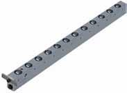
14 Roller conveyor without lifting universal use Roller conveyor, segment 250 mm Roller bar width A Max. load (kn) Segment length Max. load/roller (kn) Roller Ø B C Ø d ,4 6,4 8,0 16 x x x 12 39,5 49,5 62, These universal roller conveyors have been developed for easy and safe conveying of heavy dies. All roller conveyors are manufactured in segments of 250 mm to which further segments can be added until the desired length is obtained. The basic bodies of the roller conveyors are made of a high-strength and robust aluminium alloy. The roller bars are fastened through mounting holes provided in the segments. HILMA also supplies longer single-piece roller conveyors. Other variations A closer arrangement of the rollers increases the load-carrying capacity Increased load-carrying capacity achieved by package design Overall lengths of max mm in a single-piece design are possible.
15 Carrying consoles for easy and efficient die change on the press bed Colour: RAL 1004, golden yellow Carrying console, hanging The carrying consoles are hung in the hooks on the die changing side of the press. The hooks are supplied with the consoles. The consoles are used as a pair. Their size must be selected to suit the highest die weight. The die is loaded onto the consoles using a crane or a forklift truck. The carrying rollers consist of high-strength hardened needle bearings. The end stop can be bypassed in one direction. The surface is provided with a shock-resistant coating in RAL 1004, golden yellow. Hanging consoles may be used for several presses. In this case, an additional set of hooks is required. Carrying console, supported In order to cope with heavy and large dies, the console is provided with an additional support. For compensating for unevenness on the floor, the supports are designed as adjustable supports with a ball-andsocket joint. The height may be changed subsequently by ±60 mm. The end stop can be bypassed in one direction. Konsole Typ 1835 Traglast/Paar k Carrying console, swivelling This console is permanently fastened to the press bed and can be pivoted into the die changing position. This type is particularly recommended when the available space in front of the press bed is limited, or if removal and intermediate storage of the console is not possible or wanted. For carrying rollers, end stop and surface coating, see above. Special designs of carrying consoles are available on request
16 Carrying console, hanging Locking pin DIN Ø 16 x 40 Cheese head screw DIN 912-M 16 x 110-8,8 Ma = 120 Nm Hole pattern Press bed Hook Console Scope of supply: 2 carrying consoles (1 pair) 4 hooks for 1 pair Max. load/ pair (kn) Length of support Dimensions (L) a+1 b c ±0,1 d h Weight/pair (kg) M16 Ø M16 Ø M16 Ø M16 Ø M16 Ø M16 Ø M16 Ø M16 Ø M16 Ø M16 Ø hooks are supplied with the consoles available at short notice 1 additional set of hooks (= 4 OFF) part no (40 kn)
17 Bed upper edge Carrying console, supported Console kn Locking pin DIN 1481 Cheese head screws DIN 912 M16 x110, 8.8 M a = 120 Nm Locking pin DIN 1481 Ø16 x 40 Cheese head screw DIN 912 Console kn Bed upper edge Cheese head screws DIN 912 M16 x 50 und M16 x 110 M a = 120 Nm Locking pin DIN 1481 Ø16 x 50 Console kn Bed upper edge Press bed Hook When ordering, please specify the exact height of support Scope of supply: Console 2 carrying consoles (1 pair) 4 hooks 2 supporting feet Support please specify support high (+/-60 mm) Support with ball-and-socket joint (+/-60 mm) Cheese head screws DIN 912 M24 x 80 und M24 x 160 M a = 250 Nm Locking pin DIN 1481 Ø20 x 100 Threaded holes M16 for eye bolts (transport by means of fork stacker) for 1 pair Max. load/pair (kn) M16 Ø M16 Ø M16 Ø M16 Ø M16 Ø M16 Ø M16 Ø M16 Ø M16 Ø M16 Ø M16 Ø M16 Ø M16 Ø M24 Ø M24 Ø M24 Ø M24 Ø hooks and 2 supports are supplied with the consoles available at short notice Length of support Dimensions (L) a+1 b c ±0,1 d e f h x Example of ordering: , SH 1000 console 1000 mm long max. 20 kn height of support 1000 mm 1 additional set of hooks (= 4 OFF) part no (40 kn), part no (100 kn), part no (250 kn) Weight/pair (kg)
 4 holders (premounted) The")
18 Carrying console, swivelling Hole pattern Holder Console Cheese head screws DIN 912 M16 x 40, 8.8 M a = 120 Nm Locking pin DIN 1481 Ø10 x 50 Lock Locking pin DIN 1481 Press bed Cheese head screw DIN 912 Scope of supply: 2 carrying consoles (left and right side) 4 holders (premounted) The carrying console is swivelling on the left and right side for 1 pair Max. load/pair (kn) Length of support Dimensions (L) a ±0,2 b ±0,1 c ±0,1 d e g h i k ±0, M16 Ø , M16 Ø , M16 Ø , M16 Ø , M16 Ø , M16 Ø , M16 Ø , M16 Ø ,5 Carrying consoles are supplied in pairs with holders fastened, ready for connection Special designs and double-swivel consoles are available on request. Special designs of carrying consoles, e.g. sliding carrying consoles are available on request


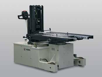
19 Die changing station Dies up to a weight of 200 kn Die changing system directly adapted to the press This new die changing system with special push- and-pull drive makes handling of dies easier and ensures time-saving and accident-free movement of dies with a maximum weight of 20 tons in places difficult to access. (Higher load-bearing capacities on request) Description: The cost-effective drive system has been developed on the basis of standard die consoles and can be easily installed as it requires only little space. Thus, it is very suitable for both retrofitting and new constructions. The drive unit and the carrying console are hung in hooks provided on the press for this purpose and then locked. The die is deposited on the consoles using a crane or a forklift truck. After the die has been deposited, it can be connected to the changing station by means of a pushand-pull system. The integral chain drive system allows the user automatic die loading and positioning, just by depressing a pushbutton on a separate remote control pendant. During a die change, the press bed is free, i.e. the pushand-pull elements do not project over the press bed. Also the rear side of the press is completely free. This changing station is suitable for almost any press, can be easily removed and is easy to handle. Special features: Besides the reduction of non-productive set-up time, the die changing system offers further important benefits to the user: maximization of profits due to less downtime smaller production batches are possible due to shorter set-up times greater safety for man and machine safe and accident-free handling of dies with less effort, thus creating a more humanised place of work Roller and ball bars in the T-slots of the table provide for easy insertion of the die, either manually or automatically. Damage to the die causing production loss is avoided. Individual solutions including automatic die changing and integration in the press are possible


20 Die changing station Variations of the die changing station Version with a driven central console and two standardtype carrying consoles on the right and left side. This cost-effective alternative is flexible and can be used on various presses. Version with two driven and synchronized consoles. This extremely robust and precise alternative is suitable for almost all die sizes and geometries

21 Small power unit Power unit, compact bar Power unit especially for use with hydraulic roller and ball bars Supplied as a compact unit, ready for use. The power unit operates intermittently under automatic pressure control, i.e. when the set pressure is reached the motor is automatically switched off. If pressure drops 10% below the set value the pressure switch causes the motor to start again. Optional extras: Pressure relief valve Pressure switch Remote control pendant Oil level and temperature switch Equipment clamping circuit, 1 x single-acting with oil level and temperature indication with pressure relief valve and pressure switch with electrical controls and remote control pendant, with selector switch For other compact power units and clamping pumps, please see product group /2011


22 Foot operated pump, 400 bar Special features: foot-operated pump of lightweight construction, low weight, low pedal-actuating force required easy maintenance and operation using an externally adjustable pressure relief valve laterally fitted pressure gauge suitable for up to 700 bar bottom made from steel sheet provided with rubber feet which may be removed, e.g. when screw-fastening the pump A B E J K V X Y W G 1/4 Technical data: Max. operating pressure: 400 bar Delivery per stroke: 2.2 cm3 Pedal-actuating force: 490 N Tank volume: 0.24 litres Useful volume: 0.19 litres Weight: approx. 3.5 kg Hydraulic hand pump bar Especially designed for use in combination with hydraulic roller or ball bars for lifting dies during a die change. Special features: lifting and lowering of the bars using only one lever pressure relief valve infinitely variable optionally foot operated compact, closed design Hilma-Romheld hand pump with manual operation and flanged connection for use on a press bed Max. operating pressure (bar) Delivery per stroke (cm 3 ) Usable oil volume (cm 3 ) Hydraulic connection Weight (kg) G 1/4 G 1/4 7,3 7,
Die changing technique
 Die changing Die changing 8 Contents Product group 8 Roller bar, hydraulically lifted for heavy loads (400 bar), lifting of the complete roller bar for medium loads (120 bar), lifting of individual rollers
/2015. Roller and ball bars for easy and safe die change
 Roller and ball bars for easy and safe die change T-slot tolerances acc. to DIN 650 h h n a b c min. max. max. 18 H8 30 +2 12 +2 30 36 1,6 22 H8 37 +3 16 +2 38 45 1,6 28 H8 46 +4 20 +2 48 56 1,6 36 H8
Hydraulic clamping elements
 Hydraulic clamping elements hydraulic 3 Contents Product group 3 Hollow piston cylinder single-acting 3.1403 3.2130 Sliding clamp single-acting compact classic 3.2202 3.2204 Angular clamping element single
/2017. Swing sink clamping element double-acting
 Applications: integrated in press rams integrated in press beds in machine tools and equipment when the available space is limited when temperatures may reach 70 C For power units please see product group
ALFRA PRESS - overview
 70 ALFRA PRESS 71 ALFRA PRESS - overview ALFRA PRESS AP 250 ALFRA PRESS AP 400 Page 74 Page 78 Control cabinet housing, Control cabinet doors, Mounting panels Control cabinet housing, Control cabinet doors,
Suspension System CS-3000
 Suspension System CS-3000 Straight coupling Elbow coupling (colour) 1015300177 RAL 9006 white aluminium 1015300001 RAL 16 anthracite grey 101530017 RAL 9006 white aluminium 1015300002 RAL 16 anthracite
Conveyors 12. slide strips roller Conveyors roller elements Conveyor rollers Chain Transfer
 Conveyors slide strips roller Conveyors roller elements Conveyor rollers Chain Transfer Application example conveyors Transport solutions and goods provision 1 2 3 4 5 6 7 8 362 9 1 slide strips Low-wear
Dynamic Elements Linear Slides Mechanical Drive Elements Accessories for Mechanical Drive Elements
 8 Dynamic Elements Mechanical Drive Elements Accessories for Mechanical Drive Elements The Dynamic Elements product group of the MB Building Kit System contains components which enable precise linear movement.
/2017. Hollow piston cylinder, single-acting spring clamping hydraulic unclamping
 , single-acting spring clamping hydraulic unclamping Applications: un-pressurized long-term clamping of dies or fixtures on press beds and rams when the space available is limited T-bolt Spring clamping
Wedge clamps
 Wedge clamps Wedge clamps for dies with tapered clamping edge Without position monitoring up to 160 C* 2.24000 With position monitoring lateral fastening up to 100 C** 2.24001 With position monitoring
L I F T I N G C A R T S
 L I F T I N G C A R T S LIFTING CARTS The prograe for lifting, transporting and storage From the classical forklift trolley to the machine lifter, from furniture dollies to a chassis with 24 tons load
01 Product overview KT series order picking trolleys MultiPick trolley Pick and Pack Order picking container
 01 Product overview 01.01 01.09 KT series order picking trolleys 01 KT1 02 KT2 03 KT3 04 KT4 05 KT DRIVE 06 KT3-KOMBI 07 KT ALU 08 KT-R 09 KT-B 01.10 MultiPick trolley 01.11 Pick and Pack 10 MULTIPICK
Roller guide actuator/guides - SQ /SQZ
 Roller guide actuator/guides - SQ /SQZ Timing-belt unit with optimum connecting options due to slots in guide profile/carriage Fixing slots 9Easy 9 fixing of linear actuator 9Simple 9 connection of accessories
The BERNSTEIN CS-3000
 Flexible and efficient: The BERNSTEIN CS-3000 Designers and manufacturers expect modern suspension systems to feature variable configuration, progressive design and complete ease installation. BERNSTEIN
Profile guide/actuator - RK Compact
 Profile guide/actuator - RK Compact Slimline short-stroke linear actuator for hand adjustment with excellent price-performance ratio Control knob with vernier Simple adjustment of carriage Backlash of
Mechanical equipment Pneumatic stamping-unit Hand-toggle-lever presses
 Mechanical equipment Pneumatic stamping-unit Hand-toggle-lever presses Mechanical equipment ST 1092 ST 1292 page 7.03 ST 9041 page 7.04 ST 9062 page 7.05 ST 9067 page 7.05 ST 9072 page 7.06 ST 9075 page
GTK 80. Technical data
 Industrial square suspension system with open cable duct for heavy loads Modular construction with free accessible cable duct Floor, top-mounting or wall exit options Technical data Material: connecting
Contents. Page. 1. Product description. 2. The AXC line of linear axes. 3. AXLT line of linear tables. AXC and AXS product overview...
 SNR Industry Contents Page 3 1. Product description AXC and AXS product overview... 6-8 Dynamic load ratings of the linear motion systems... 9 Compact modules... 10-11 Linear tables... 12 Telescopic axes...
Profile series I-40. System kit Profile series I-40
 Profile series I-40 System kit Profile series I-40 n n n a n n n R n a R 45 Profile series I-40 Contents 1 Technical data/profile machining F f Page 1 2 Page 1 3 Page 1 5 Page 1 8 Profiles Page 2 2 3000
B Precision Ground Plates and Flat Bars. E Ground Precision Components. G Elastomer-Bars, -Sheets, -Sections
 A Die Sets B Precision Ground Plates and Flat Bars C Lifting and Clamping Devices Shanks, Lifter Studs and Lifting Hooks, Eyebolts Clamping Claws, Screws and Bolts D Guide Elements E Ground Precision Components
Workspace and storage furnishings
 LISTA Compact Workspace and storage furnishings Universal superstructures Utmost stability load capacities up to 10 kg Tremendous design diversity through a wide range of add-on elements including power
L Standard Parts for Mould Making
 A Die Sets B Precision Ground Plates and Flat Bars C Lifting and Clamping Devices Shanks, Lifter Studs and Lifting Hooks, Eyebolts Clamping Claws, Screws and Bolts D Guide Elements E Ground Precision Components
Machine elements. Pneumatic stamping unit. Toggle-lever presses
 Machine elements Pneumatic stamping unit Toggle-lever presses Machine elements ST 1292 ST 1092 Page 7.03 ST 9041 Page 7.04 ST 9061/62 Page 7.05 ST 9067 Page 7.05 ST 9070/72 Page 7.06 ST 9075 Page 7.07
> clamping force up to kn. > operating pressure up to 500 bar. > piston with internal thread. > for push- and pull operation
 Block CYLINDERS for VARIOUS DESIGN APPLICATIONS > clamping force up to 155.5 kn > operating pressure up to 500 bar > piston with internal thread > for push- and pull operation > with longitudinal and cross
INDUSTRIAL VACUUM SYSTEMS MADE AND MANUFACTURED IN GERMANY RANGE OF ACCESSORIES COMPETENCE CENTRE INDUSTRIAL VACUUMING. Valid from
 INDUSTRIAL VACUUM SYSTEMS MADE AND MANUFACTURED IN GERMANY Valid from 01.01.2019 COMPETENCE CENTRE INDUSTRIAL VACUUMING 2 3 DEAR CUSTOMER, This catalogue provides you with an essential selection of the
Steps for self-assembly 100 S C.08 Steps for self-assembly 100 L C.10 Steps for self-assembly 75 L C.12 Industrial ladders C.13
 Step system Technical information Test marks Your Partner in matters of safety Founding member of the German Ladder and Mobile Scaffolding Association Founding member of the European Ladder Federation
Assembly Products. View Assembly Products at: LINEAR ACTUATORS AND MODULAR UNITS FOR YOUR APPLICATION
 Assembly Products LINEAR ACTUATORS AND MODULAR UNITS FOR YOUR APPLICATION View Assembly Products at: www.clrh.com (636) 386-8022 www.clrh.com Drive, Assembly and Handling Technology Linear Actuators n
Heavy-Duty Suspension System CS-2000 System 80
 Heavy-Duty Suspension System CS-2000 System 80 With its large number of components, the BERNSTEIN CS-2000 System 80 suspension system offers technically perfected solutions for a wide range of applications.
ZERO-POINT CLAMPING SYSTEM
 simple. gripping. future. ZERO-POINT CLAMPING SYSTEM 22 Quick Point Grid Plates 3 Quick Point Plates 34 Quick Point Round Plates 39 Quick Point Adaptor Plates 4 Quick Point Clamping Studs 43 Quick Point
WPP 15 T - Hydraulic table shop press with manual pump and mobile cylinder for professional use
 Hydraulic shop presses WPP 15 T - Hydraulic table shop press with manual pump and mobile cylinder for professional use For all repair and assembly works, e.g.: Straightening Robust frame with perforation
Selection Tool. on the Internet at in the section MÄDLER -Tools. Other sizes and designs on request. Connecting Shafts Page 766
 Couplings Overview Friction Clutches Friction Clutches Type B Axial Arrangement Friction Clutches Type C Transversal Flexibility Sliding Hubs with Torsionally-Flexible Coupling Multi-Disk Friction Clutches
Scope of delivery: Lid and base, fixing screws, RO versions with aluminium front panel, 4 rubber feet.
 Futura / Portas These flat control or keypad enclosures were designed especially for EDP workplaces and according to ergonomic guidelines. In these product series you will find enclosures with a ball-of-the-thumb
Cam roller guide LF12S complete axis
 Y -16 MGE. Linear guides Z Mz Cam roller guide LF1S complete axis X Mx M y [mm] B [mm] Fully assembled cam roller guide Stroke and trolley length can be individually selected Rail profile screwed onto
Ball Rail Systems RE / The Drive & Control Company
 Ball Rail Systems RE 82 202/2002-12 The Drive & Control Company Rexroth Linear Motion Technology Ball Rail Systems Roller Rail Systems Standard Ball Rail Systems Super Ball Rail Systems Ball Rail Systems
GeneralInformation General General. General General. General General General General General General General General General General General
 information Information 1 Why die clamping systems? Cost manual die change It will pay for itself! automatic die change Innovative technology and many years of experience are the basis for our range of
Standard Knockout Punches 10. Punch Kits for Hydraulic Drivers 11. Draw Stud Selection Guide 13, 14, 18. Special Shape Punches
 8 Punching Tools, Hole Saws, Step Bits Page Punching Tools Standard Knockout Punches 10 Slug Buster Knockout Punches 10 Slug Splitter Knockout Punches 10, 12 Punch Kits for Hydraulic Drivers 11 Draw Stud
Cam roller guide LF6S complete axis
 Y 1- MGE 1. Linear guides Z Mz Cam roller guide LFS complete axis X Mx M y [mm] B [mm] Fully assembled cam roller guide Stroke and trolley length can be individually selected Rail profile screwed onto
ACCESSORIES STEPS AND FOOT PINS
 ACCEORIE TEP AND FOOT PIN Hang-on step for rung ladders For rung dimensions 30 x 30 mm. For ladders with an internal width of at least 300 mm. Rung spacing 280 mm. tep width 300 mm. tep depth 255 mm. Maximum
Heavy duty cylinder LZ 70/80 TR PL
 Heavy duty cylinder LZ 70/80 TR PL The new generation of industrial linear cylinders Drive options for LZ FL/PL: 9Compatible 9 with all motor manufacturers and types Push rod 9Protection 9 against rotation
Profi le rail guides LLR
 Profi le rail guides LLR Content The SKF brand now stands for more than ever before, and means more to you as a valued customer. While SKF maintains its leadership as the hallmark of quality bearings throughout
Konsole Typ Traglast/Paar kg
 Carrying consols for asy an fficint i chang on th prss Konsol Typ 1835- Konsol Typ 1835- Colour: RAL 1004, goln yllow Carrying consol, hanging Th carrying consols ar hung in th hooks on th i changing si
Figure 8-1. Frame and External Parts - Coil Chain Models.
 Figure 8-1. Frame and External s - Coil Chain Models. Ref. Quantity Required 1/4 Ton 1/2 Ton 1 Ton 1 BAH-105 Bolt - Suspension Bracket 2 2 2 2 BAH-108 Lockwasher - Shakeproof, External 2 2 2 3 BAH-107
Light/Energy. Halogen floodlight. Fire Brigade 500 W halogen floodlight. Fire brigade 1000 W halogen floodlight. Quality since 1903
 Halogen floodlight Fire Brigade 500 W halogen floodlight The Dönges 500 W floodlight is a top quality, cost-efficient halogen operational floodlight with special modifications for the fire brigade and
The new BERNSTEIN Aluminium Suspension System
 CS-3000 next Suspension Systems The new BERNSTEIN Suspension System The CS-3000 next combines functionality with an appealing design. The new system is an important addition to the CS-3000 series, it is
Event. Road construction. Event. Mobile fence. Building construction. Civil engineering. Storage equipment. Transport equipment
 42 Crowd barrier Urban Equipment Building Equipment Crowd barrier type D steel construction of Ø 33.7 mm round tube, hooks and connection brackets are welded to the sides for combining several elements,
Chapter 5: Flow Valves
 Catalogue HY11-300/UK Contents Chapter : Flow Valves Series Description Size Mounting Page Parker Standard DIN / ISO 1/4 3/8 1/2 3/4 1 06 10 16 Throttle valves, manual adjustment MVI -2 NS -4 FS With free
RK Monitor Mounting... page 254. GT page 264. GT 50, 60, page 274. Support arm / equipment carrier system
 Support arm / equipment carrier system RK Monitor Mounting... page 254 GT 48... page 264 GT 50, 60, 80... page 274 Support arm / equipment carrier system RK Monitor Mounting All purpose mounting for monitors,
HYDRAULIC JACKS & TOOLS
 HYDRAULIC JACKS & TOOLS 323 Hydraulic jacks & tools Table of contents Page A characteristic of this force-oriented hydraulic Hydraulic cylinders, single-acting program is the operating pressure which can
Product overview. Joints. Circlips for ball seats DIN K0714. Quick plug couplings with radial offset compensation K0709. Page 837.
 Joints 825 Product overview Joints Quick plug couplings with radial offset compensation K0709 Quick plug couplings with radial offset compensation and screw-on flange K0710 Quick plug couplings with angular
Accessories smart additions for efficiency and intelligent performance
 smart additions for efficiency and intelligent performance Metal bellows couplings Perfectionists you can count on Metal bellows couplings are designed for the highest requirements in servo drive technology.
Valve Lapping Tool Attachment. Valve / Valve Spring Tools / Jacks / Axle Stands. 27-piece Valve Seat Cutter Set, mm
 Valve Lapping Tool Attachment - facilitates the insertion of valves - automatic change in direction - for use with fine grinding paste - with 8 mm shank - working speed min. 1000 rpm, max. 1250 rpm - 2
RACK JACK. Synchronous Lifting Systems
 RACK JACK Synchronous Lifting Systems RACK JACK (ROUND RACK TYPE) Operation The Rack Jack from WMH Herion provides simple synchronous lifting motion. The system of rack and pinion transforms linear motion
ORIGA Pneumatic Linear Drives OSP-L
 ORIGA Pneumatic Linear Drives OSP-L Very long lifetime and lowest leakage A NEW Modular Linear Drive System With this second generation linear drive Parker Origa offers design engineers complete flexibility.
Linear guides MGE 13.2 Linear guides
 13-2 MGE 13.2 Linear guides Linear guides For constructing linear guides based on cam roller guides Cam roller guides are suitable for applications with high speeds and medium loads, in particular for
Keystone F89 pneumatic quarter-turn actuator General purpose / hazardous area
 Compact, reliable and low operation costs for all types of quarter-turn valves are the keywords of the Keystone F89 range of pneumatic actuators Features Direct mounting to all Keystone butterfly valves
KEYSTONE F89 pneumatic quarter-turn actuator GENERAL PURPOSE / HAZARDOUS AREA
 compact, reliable and low operation costs for all types of quarter-turn valves are the keywords of the Keystone F89 range of pneumatic actuators FEATURES Direct mounting to all Keystone butterfly valves
Shaft Couplings Flange-Couplings Rigid Shaft Couplings Flexible Couplings
 Shaft Couplings Flange-Couplings Rigid Shaft Couplings Flexible Couplings 44 Edition 2013/2014 RINGSPANN Registered Trademark of RINGSPANN GmbH, Bad Homburg 2 Table of Contents Flange-Couplings Page Flange-Couplings
Pneumatic Power Valves Series 75/76 Manual, Mechanical, Pneumatic and Electric Valves
 Quic-Pics Catalogue Pneumatic Power Valves Series 75/76 Manual, Mechanical, Pneumatic and Electric Valves Contents: Product Line Overviews 2 Manually Operated Valves 5 Pushbuttons 6 Toggle Switch 8 Knob
Universal. CNC Turning machine TNA500 TNA600
 Universal CNC Turning machine TNA500 TNA600 TRAUB TNA this name is highly regarded throughout the world for machining large chuck, shaft or bar parts. With their precision and efficiency, short setup time
Hahn Serie 60 AT. Universal hinge for versatile application. More modern look Improved technology
 Hahn Serie 60 AT Universal hinge for versatile application! More modern look Improved technology 2 4 5 6 7 8 9 2 3 4 5 6 7 8 9 2 Hahn Serie 60 AT For all doors made from metal profile sections NEW! Uniform
Precision levelling wedges Due to their large contact area Bilz precision levelling wedges (PK) for vibration and structure-borne noise insulation
 for vibration and structure-borne noise insulation") 28 Precision levelling wedges Due to their large contact area Bilz precision levelling wedges () for vibration and structure-borne noise insulation offer optimum support and stiffening of the machine bed.
28 Precision levelling wedges Due to their large contact area Bilz precision levelling wedges () for vibration and structure-borne noise insulation offer optimum support and stiffening of the machine bed.
Guide units. For toolmaking, fixture manufacturing and machine engineering
 Guide units For toolmaking, fixture manufacturing and machine engineering Guide units in compliance with DIN, ISO and STEINEL standards or according to your specifications Guide pillars Guide and pillar
KTR Torque Limiters Overload Protection Systems
 KT Torque Limiters Overload Protection Systems UFLEX - Friction Disk - Zero Backlash Ball Detent KT SI - Ball/oller Bearing Style KT SI Compact - Zero Backlash Ball Detent Catalog Contents (Metric) Page
Type 2 Push-Through 37 Ton Log Splitter. Assembly Manual
 Type 2 Push-Through 37 Ton Log Splitter Assembly Manual Refer to this manual for the following models: RS37PT-LF09PC-16-1 RS37PT-LF09EC-16-1 RS37PT-LF09EC-16-2 RS37PT-LF13EC-22-1 RS37PT-LF13EC-22-2 RS37PT-LF15EC-22-1
Suspension Systems. Quality Commitment
 Suspension Systems Since 1984, Altech Corporation has grown to become a leading supplier of automation and industrial control components. Headquartered in Flemington, NJ, Altech has an experienced staff
Ram Cushions and Pressure Parallels Dynamic Solutions For A Global Market
 Nitro-Dyne Ram Cushions and Pressure Parallels APPROVED 97/23/EC Dynamic Solutions For A Global Market Nitro-Dyne Ram Cushions and Pressure Parallels Table of Contents Page Introduction...2 The Advantages...3
LVE - with integrated pneumatic cylinder
 LVE - with integrated pneumatic cylinder APPLICATION Optimally suited for flange, bar and tube machining, especially for machines without a clamping cylinder. TYPE Power chuck with integrated pneumatic
Compressed Air and Electric Supply System Program C40
 Compressed Air and Electric Supply System Program C40 Table of Contents Overview 4 Product Description...4 System Overview....4 Rail Components 5 General Information...5 Load Diagram....5 Rail Couplers....6
MANUAL HOISTING TAKE THE WEIGHT OUT OF HEAVY DUTY LIFTING
 MANUAL HOISTING TAKE THE WEIGHT OUT OF HEAVY DUTY LIFTING CARE & SAFETY INSTRUCTIONS 114 CX & M3 SERIES CHAIN BLOCKS 115-117 C SERIES CHAIN BLOCKS 118 MINI II CHAIN BLOCKS 118 LX & L5 SERIES CHAIN BLOCKS
SCM M2. Other advantages:
 Sunfab s SCM 025-108 M2 is a range of robust axial piston motors with cartridge flange especially suitable for winch-, slewing-, wheel- and track drives. SCM 025-108 M2 is of the bent-axis type with spherical
Manual clamps Industrial standard
 Manual clamps Industrial standard Modular clamps The modular clamp kit. In connection with a standard ISO cylinder and a clamp bracket, fully equipped pneumatic clamping points can be assembled with the
Support legs. Installation and operating instructions
 Support legs Installation and operating instructions Table of contents 1 Explanation of symbols... 3 2 Assembly... 4 3 Operation... 5 4 Servicing and testing... 8 2 MUB 013 001 M01 (REV--) 11/2016 Support
Material: Hinge Parts: zinc die, matt chrome plated, or zinc die, matt black. Pin: stainless steel Nut plate: steel, zinc plated
 4-249 Hinge Pr01 180 Small elegant hinge. 180 Opening. Adjustments are possible with respective bores provided. The nut plate can be mounted in different ways, according to the application. zinc die, matt
Zero Point Clamping System classic 3
 Zero Point Clamping System classic 3 Set your manufacturing to Nullpunkt Spannsystem GO! Maximum productivity - even with large parts Using the zero point clamping system SPEEDY classic you will increase
Keystone F89C Pneumatic Quarter-Turn Actuator Chemical Industry / Hazardous area
 The F89C addresses the specific requirements for automated quarter-turn valves in the chemical industry on top of the reliability and low maintenance cost offered Features Valve connection compatible with
For advanced drive technology CLAMPEX. Shaft-hub-connection. KTR Precision joints CLAMPEX
 technology CLAMPEX Shaft-hub-connection CLAMPEX KTR Precision joints 227 technology Table of contents Page Brief information 228 Selection and calculation 25-255 CLAMPEX -Selection Shaft diameter = d 0
MOTOR SCM M2
 MOTOR SCM 025 108 M2 Sunfab SCM M2 is a range of robust axial piston motors especially suitable for winch-, slewing-, wheeland track drives. Sunfab SCM M2 is of the bent-axis type with spherical pistons.
NOMENCLATURE. Optional: V = Viton FKMsealing. RÖHM Z centric gripper Pneumatic. Sizes A = Alternative jaw fixture by tongue and groove
 NOMENCLATURE RZP -A - 100-1 / GA / V RÖHM Z centric gripper Pneumatic A = Alternative jaw fixture by tongue and groove Sizes 64-300 Jaw stroke variant 1 = long stroke 2 = short stroke Optional: spring
Hydraulic Jacks & Tools Test rig
 ydraulic Jacks & Tools Test rig ydraulic test rig for hoisting equipment model RPYS-1215 Capacity max. 12 t or testing pul-lifts, lever hoists, chain blocks, wire rope pullers as well as other lifting
Power Workholding. Power Workholding n Precision Vises n Zero Point Mounting n Assembly and Handling
 Power Workholding Power Workholding n Precision Vises n Zero Point Mounting n Assembly and Handling OUR STORY In 1982 an independent joint venture was established to marry the proven product expertise
Aluminium Productive Fence System 40 PRODUCT CATALOGUE
 11 2017 (e) Aluminium Productive Fence System 40 PRODUCT CATALOGUE solutions by F.EE Elektrotech Engineering Automation Robotik Informatik + Systeme Energietechnik F.EE GmbH In der Seugn 10 and 20 D-92431
SCHMIDT PneumaticPress
 Maximum pressing force from 1.6 kn to 60 kn The SCHMIDT PneumaticPress range consists of a modular system suitable for transforming, joining and assembling operations optimally within the pressing capacities
Hytrol's ABC Conveyor Book
 Hytrol's ABC Conveyor Book WHAT IS A CONVEYOR? A conveyor moves material. A conveyor moves cardboard boxes, wood boxes, metal boxes and plastic boxes. A conveyor can move material This is called a GRAVITY
Roller guide actuators - SQ ZST
 Roller guide actuators - SQ ZST Rack and pinion with fixed carriage, also for larger travels up to 30 m RK Standard motor 9Choice 9 of motor and motor adaptor plate to suit your requirements 9 9Simple
Precision Modules PSK
 Precision Modules PSK The Drive & Control Company Rexroth Linear Motion Technology Ball Rail Systems Roller Rail Systems Standard Ball Rail Systems Super Ball Rail Systems Ball Rail Systems with Aluminum
SCM ISO. SCM ISO is a range of robust axial piston motors especially suitable for mobile hydraulics.
 SCM 010-130 ISO is a range of robust axial piston motors especially suitable for mobile hydraulics. SCM 010-130 ISO is of the bent-axis type with spherical pistons. The design results in a compact motor
Clamping Tools
 Clamping Tools Drill chuck Tapping chuck/ tapping machines Taper bore tools HSK inserts Tool holder for lathes Tool pre-setter 1 1.3 1.8 Reduction sleeves Spindle Sleeves Ejector Drifts Adapter sleeves
Suspension tracks. Suspension tracks H 38. We put things in motion
 H 38 Our manual suspension tracks are also suitable for small and medium-sized trade companies. They are particularly distinguished by: Overhead conveyor system with Müsing spider assembly. Targeted material
Technical data/component parts
 Technical data/component parts Demag pillar and wall-mounted slewing jib cranes 191214 en GB 203 814 44 714 IS 132 Manufacturer Terex MHPS GmbH Forststrasse 16 40597 Düsseldorf, Germany www.demagcranes.com
Instruction and Installation Manual
 Instruction and Installation Manual ROSTA Tensioner Devices Tensioners Accessories -G -W -R Sprocket wheel N Chain rider P Oil resistant Up to + 120 C Reinforced Sprocket wheel set Chain rider set -I -F
Small cases... the perfect shell for valuable electronics
 Small cases... the perfect shell for valuable electronics Small cases page 178 mini page 181 page 183 all standard size cards (100, 120, 160, 190 to 233,35 ) can be installed in one case favourable EMC
SITEMA PowerStroke. Technical Information TI-P11. 1 Function. 2 Applications. Mould Closing Devices series FSK. Contents
 SITEMA PowerStroke FS ocking, actuating and releasing by hydraulic pressure English translation of German original Technical Information TI-P11 SITEMA PowerStroke Mould Closing Devices series FS TI-P11-EN-01/016
LOCKED SERIES. Machine Failures. General Information. set up. maintenance. reconditioning. repair 30.4%
 General Information LOCKED SERIES 2 Lowering machinery process costs is key in today s world. According to a recent study approximately a third of all machine stoppages result in unexpected damage and
RACK JACK. Synchronous Lifting Systems
 RACK JACK Synchronous Lifting Systems RACK JACK (ROUND RACK TYPE) Operation The Rack Jack from WMH Herion provides simple synchronous lifting motion. The system of rack and pinion transforms linear motion
Hakki Pilke 42 Easy FIREWOOD PROCESSOR SPARE PARTS MANUAL
 ENGLISH Hakki Pilke 42 Easy FIREWOOD PROCESSOR SPARE PARTS MANUAL MAASELÄN KONE OY Valimotie 1, 85800 Haapajärvi tel.08-7727300, fax.08-7727320 info@maaselankone.fi www.maaselankone.fi 2 Table of contents
00000 Series Clevis Pin Slotted Hexagon Hex Key Recommended Corresponding Part No. Part No. Size Torque Preload SLT* SLT* HEX
 00000 Series Clevis Pin All clevis pins are manufactured from heat treated 416 stainless steel to provide superior strength and wear. Hardness is between 37-40 Rc. The DCD Clevis Pin is a shouldered type
Brake System H TX, H2.0TXS [B475]; H TX [B466] Safety Precautions Maintenance and Repair
![Brake System H TX, H2.0TXS [B475]; H TX [B466] Safety Precautions Maintenance and Repair](/thumbs/86/93834005.jpg "Brake System H TX, H2.0TXS [B475]; H TX [B466] Safety Precautions Maintenance and Repair") HMM180001 Brake System H1.5-1.8TX, H2.0TXS [B475]; H2.5-3.5TX [B466] Safety Precautions Maintenance and Repair When lifting parts or assemblies, make sure all slings, chains, or cables are correctly fastened,
HMM180001 Brake System H1.5-1.8TX, H2.0TXS [B475]; H2.5-3.5TX [B466] Safety Precautions Maintenance and Repair When lifting parts or assemblies, make sure all slings, chains, or cables are correctly fastened,
Product features & Overview. KA Linear actuators
 Product features & Overview Linear actuators 66 Linear actuators Linear actuator Product features Wide range of force outputs Solid metal housing Large stroke range Maintenance-free gearbox Wide range
SCHMIDT ManualPress From 1.6 kn to 22 kn / 360 lbs. to 4,945 lbs.
 SCHMIDT ManualPress From 1.6 kn to 22 kn / 360 lbs. to 4,945 lbs. Efficient manufacturing requires appropriate means of production not always automation. In particular, with small production runs, manual
Norden. A Lancashire Mill Engine. Scale: 1:12
 Scale: 1:12 Neil M. Wyatt February 2009 Fig. 1: General Arrangement General Arrangement Sheet: 1 An Old Steam Engine DEAR SIR, In the ruins of an old mill at, near Rochdale, there is an old steam engine