... RTU Technical Manual. Packaged Air Conditioning Unit...
|
|
|
- Benjamin Mitchell
- 6 years ago
- Views:
Transcription


1 ... RTU Technical Manual Packaged Air Conditioning Unit...
2 Index. CODING AND MODELS. WORKING LIMITS. TECHNICAL SPECIFICATIONS. PERFORMANCE TABLES. TECHNICAL SPECIFICATIONS FOR OPTIONAL EQUIPMENT. ELECTRONIC CONTROL. SAFETY, TRANSPORT AND ELEVATION RECOMMENDATIONS. DIMENSION PLANS 2
3 CODIFICATION K C R I N S 3 W AASO K: Air conditioning range C: Compact air-cooled equipment R: Rooftop construction to be installed on ceiling. 1: Construction size 042: Nominal Power (refrigeration if there would be several values) In ARI conditions.. I: Application type (I: Reversible; Q: Only Heating; R: Only Cooling; U: Non Autonomous) N: Compressors type (N: Standard; D: Digital Scroll; V: Inverter; O: Others) P: Version: (S: Standard; F: Free Cooling; R: Recovery) 3: Electrical Voltage: (1: 230V/I/50Hz, 2: 230V/III/50Hz, 3: 400/III/50Hz non neutral, 4: 400/III/50Hz + neutral, 5: 230V/I/60Hz, 6: 230V/III/60Hz, 7: 400/III/60Hz non neutral, 8: 400/III/60Hz + neutral, 9: 440/III/60Hz + neutral, E: Special W: Refrigerant: (F: R404A; W: R410A; Z: R407C; U: R407F; Y: R134A; L: R407A; E: R1234ze; H: Water; N: None, nitrogen loading) In addition to this coding, the equipment is defined by an assambly code. These codes are three digits behind the letter A (Assembly). 7
4 WORKING LIMITS The Reznor WH systems refrigeration design, specially conceived, allows efficient and reliable operation in all weather conditions, between -8ºC and 48ºC in the standard version and up to 52ºC in the tropicalized option, without changing the refrigerant, and up to +55ºC in its high resistence to warm weathers version with R134a refrigerant. For heating mode, Reznor CR units allow to work in wet temperature conditions between -10ºC and +18ºC. AIR TEMPERATURE EXTERNAL CONDITIONS INTERNAL CONDITIONS STANDAR MINIMUM MAXIMUM MINIMUN MAXIMUN COOLING - 8ºC +48 ºC 14ºC BH 22ºC BH HEATING -10 ºC BH +18 ºC BH 10 ºC 27 ºC TROPICALIZED MINIMUN MAXIMUN MINIMUN MAXIMUN COOLING - 8ºC +52 ºC 14ºC BH 22ºC BH HIGH TEMPERATURE R134A MINIMUN MAXIMUN MINIMUN MAXIMUN COOLING - 8ºC +55 ºC 14ºC BH 22ºC BH 8
5 TECHNICAL SPECIFICATIONS The Reznor Rooftop ystems are manufactured in steel sheetmetal structure of high mechanical strength and corrosion resistance. Main features - Optimized design for HCF-410A refrigerant. - High energy efficiency with full load and partial load which reduces operating costs. - Low noise level through the high performance fans, as well as the anti-vibration silent-blocks assembled for compressors and refrigerant circuits. - Centrifugal fans, or opcionally radial plug-fan with EC motor in impulsion and return. - High performance electronic control until four phases. - Easily integrated with communication systems. - All components and the control are checked and tested in the factory.. - Designed and conceived for maintenance. All components are near to the machine s perimeter for a better maintenance and ease of service. Developed with the HFC410A a non-ozone depleting refrigerant with high performance latest generation scroll compressors developed by top brands, control by advanced microprocessor and high performance fans made of a composite material. All these options are designed to simplify installation to simple operations such as refrigeration and electrical connection. The design of the units is also conceived for maximum access for maintenance and service, saving money and time throughout its operational life. The Reznor rooftops include the latest technologies into its components and they have been laboratory tested under extreme conditions, proving that they are capable of operating in a wide range of climatic conditions of functioning. Our laboratories are continuously working on performance and durability tests in permanently monitored conditions, this allows our teams of technical specialists develop new solutions that are tailored to the needs of our customers. 9


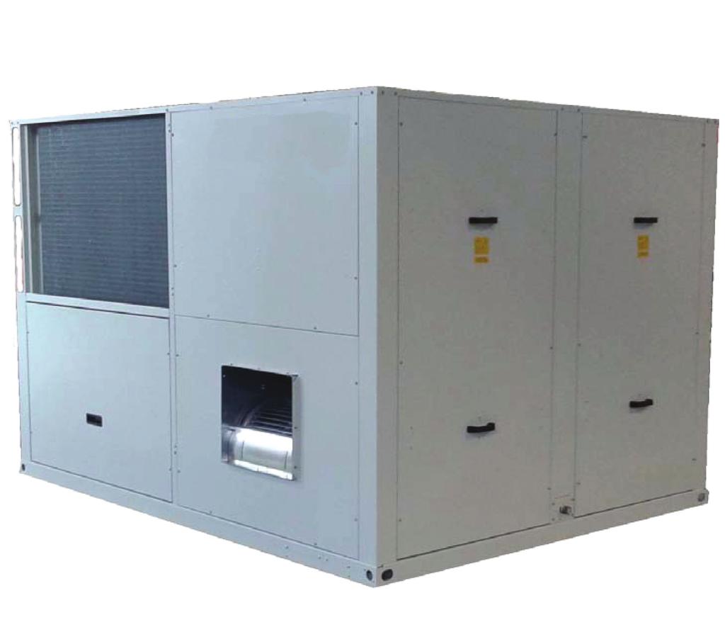
6 Structure The Reznor are manufactured as standard with self-supporting chassis of galvanized steel high zinc content. Some non-structural elements are made of aluminum for weight reduction. All machine parts are coated with oven cured polyester paint treatment. The stainless steel condensate pan is removable for an easy cleaning. Structure finishing details: On the top left, stainless removable isolated pan; on the top right, F7 filtering section, structure completely painted with thermally treated powder paint; at the bottom left, corner detail totally painted inside and out; at the bottom in the middle, motorized gate made of aluminium and completely painted inside; at the botton right, air tightness draught excluder and completely painted inside. Optionally, it is posible to produce the series AL 5000 equipments with galvanized steel selfsupporting frame and non-structural aluminium panels with high corrosion resistence. 10
7 High efficiency designed in staggered rows batteries of copper tubes and high performance aluminium fins. The condensate pan is incorporated in the external batteries of reversible models standard chassis, allowing the assembly of the equipment in an indoor technical room or designated áreas, maintaining the floors clean. Hermetic compressors scroll technology, with acoustic insulation as standard, mounted on anti vibration supports. It includes check valve in all compressors discharge, either internal or external mounted and discharge temperature sensor. Full charge of refrigerant from factory. Thermally isolated in all cold metallic lines of refrigerant or water. Electrical board with compressor protection relay with detection of phase loss, phase equilibrium control and rotation. Carter resistance electric heater for heat pump design. Thermostatic expansion valve with external equalisation specifically seleted for each heat exchanger that can be used as evaporator. Heat pump systems are equipped with two expansion valves, one of them for de internal exchanger and the other for the external one. Anti acid dehydrating filter, accumulator tank of refrigerant liquid in the heat pump systems and refrigerant liquid viewfinder. Four ways cycle reversing valve for heat pump systems. Defrost cycle through cycle reversing by four ways valve. Drop separator in aspiration of compressor standard. Protections The following protections are included as standard: - Pressure switch of low and high pressure, and thermostat of high temperature of compressor discharge - Differential pressure switch of dirty filter as standard, optionally for F filters. - Thermal protection of compressor, thermomagnetic and protection relay of phases. Differential switches as optional. - Thermomagnetic switch for the supply line of fans - General switch in electric panel. - Transport packaging for maximum protection, with pallet of reinforced wood and phytosanitary treatment according to international transport regulations. - Design of enhanced evaporator in only-cooling systems 11
8 External and internal ventilation Internal fans are equipped in centrifugal supply and return version as standard, and optionally in radial backward curved fins with EC motor incorporated. The machines are equipped with HyBlade axial external fans as standard, which are designed and developed in Europe. Constructed with an innovative and unique support structure of aluminum coated fins made of reinforced plastic with fiberglass. Its aerodynamic shape results in a huge noise reduction while as well increases its efficiency comparing with other traditional fins. Axial motor-fan units of two speeds as standard, with motor class F, protection IP54 and thermal internal protection, of low noise level and reduced weight, they have been balanced in factory for less vibration with external protection grid lacquered with polyester. Among the options of the Reznor condensing ventilation there is the high energy efficiency option with axial fans with EC technology and electronic control of condensation (XEE), low noise level (LNA), axial enhanced fans and centrifuge radials with available pressure for indoor installation with condensation driven air, all of them available with motor AC or EC. The standards units are prepared with condensate pan in the internal unit for its installation in indoor technical rooms. Electronic control The Reznor CR rooftop equipment integrates the electronic control platform CLIMANAGER TM that allows the air-to-air heat pump system complete control. It also allows the following elements conection: - Other platforms CLIMANAGER TM or PCO - Temperature and/up humidity probes (up to maximum 6 units) - Network analyzer (energy analyzer) - Electronic EBM fans - Gates servomotors. - Electronic Expansion Valves driver modules - Inverter Compressor driver modules - Digital-Scroll Compressor driver modules The CLIMANAGER TM platform can use three different types of connectivity systems: 1- By BMS platform it can be connected to a technical management system centralized in RS485 or Ethernet connection and using the communication protocols Carel, Modbus, LonWorks, BACnet, Ethernet or Konnex. 2- By Field-Bus platform it allows the communication with probes and other equipments in RS485 connection and MODBUS protocol. 3- By plan platform it allows the with PDG1 / remote PLD PRO (up to 2 units) and other CLIMANAGER TM platforms. The board is prepared to be able to remotely connect with another devices (up to maximun 15 units) by a PGD1 control without any optional element (TCONN card only). 12
9 NOMINAL POWER TABLE Model Size Indoor air flow (m3/h) Only cooling rooftop Refrigeration capacity (kw) Gross Refrigeration capacity (kw) Net Refrigeration sensitive capacity (kw) Sensitive Heat Factor Compressor Absorbed Power (kw) (1) Compressor nominal current (A) Total absorbed power (kw) EER Gross EER Net Clasification A A A A A B B C A A Heat pump unit reversible rooftop Cooling mode Refrigeration capacity (kw) Gross Refrigeration capacity (kw) Net Refrigeration sensitive capacity (kw) Sensitive Heat Factor Compressor Absorbed Power (kw) (1) Compressor nominal current (A) Total absorbed power (kw) EER Gross EER Net Clasification A A A A A B B C B A Heating mode Heating Power (kw) Compressor Absorbed Power (kw) (1) Compressor nominal current (A) Total absorbed power (kw) COP Gross COP Net Clasification A A B A A C C C A B (1) Nominal absorbed Power only for compressors (2) Refrigeration data for return air 27ºC-50% (77ºF), external temperature 35ºC (95ºF). (3) Refrigeration data for return air 20ºC 50%, external temperature 6ºC BH. (4) Nominal absorbed power (compressor motors, external and internal standar fan) 13
10 Model Size Internal air flow (m3/h) No. Compressors No. Refrigerant circuits No. Control Stages Max. Absorbed Current (A) 14,9 17,7 19,5 21,3 25,9 28,3 31,4 38,8 45,1 45,2 Length (mm) Width (mm) Height (mm) Standar unladen weight (kg) SSF assembly unladen weight (kg) Noise pressure level Lw (db(a)) Noise pressure level Lp at 10 m (dba) (4) Only cooling rooftop Refrigerant power (kw) Net (2) Heat pump unit reversible rooftop Cooling mode Refrigerant power (kw) Net (2) Heating mode Heating power (kw) (3) External Circuit Battery External air flow (m3/h) No. fans Diameter Poles Fan Absorbed Power (kw) Internal Circuit Battery Internal air flow (m3/h) Available nominal pressure (Pa) Maximun available pressure (Pa) No. Plugfan Units Standar Centrifugal fan motor (5) 0,75 0,75 0,75 1,0 1,0 1,5 2,2 2,2 2,2 2,2 Standar Centrifugal fan Absorbed Power (5) 0,50 0,55 0,55 0,80 0,90 1,15 1,30 1,50 1,45 1,55 Plugfan absorbed power (kw) (5) (1) Nominal absorbed Power only for compressors (2) Refrigeration data for return air 27ºC-50% (77ºF), external temperature 35ºC (95ºF). (3) Refrigeration data for return air 20ºC 50%, external temperature 6ºC BH. (1) Noise pressure level at 10 m distance, in free field, directivity 2 and 1,5 meters above the floor, according to standard ISO3744 (4) Absorbed power data for standard nominal point without filtering optionals. 14
11 Model Size Internal Air Flow (m3/h) Only cooling rooftop Refrigerant power (kw) Gross Refrigerant power (kw) Net Sentivie refrigerant power (kw) Sensitive heat factor Compressor absorbed power (kw) (1) Compressor nominal current (A) Total absorbed power (kw) EER Gross EER Net Clasification A A B A A A A A A Heat pump unit reversible rooftop Cooling mode Refrigerant power (kw) Gross Refrigerant power (kw) Net Sensitive refrigerant power (kw) Sensitive heat factor Compressor Absorbed power (kw) (1) Compressor nominal current (A) Total absorbed power (kw) EER Gross EER Net Clasification B A C B B B B B B Heating mode Heating power (kw) Compressor Absorbed power (kw) (1) Compressor nominal current (A) Potencia absorbida total (kw) COP Gross COP Net Clasification B C B B B B B B B (1) Nominal absorbed Power only for compressors (2) Refrigeration data for return air 27ºC-50% (77ºF), external temperature 35ºC (95ºF). (3) Refrigeration data for return air 20ºC 50%, external temperature 6ºC BH. (4) Nominal absorbed power (compressor motors, external and internal standar fan) 15
12 Model Size Internal Air Flow (m3/h) No. Compressors (5) No. Refrigerant circuits No. Control Stages Maximum Absorbed Current (A) 47,5 47,6 61,9 75,3 83,4 89,3 91,7 105,1 119,1 Length (mm) Width (mm) Height (mm) Standar unladen weight (kg) SSF assembly unladen weight (kg) Noise pressure level Lw (db(a)) Noise pressure level Lp at 10 m (dba) (4) Only cooling rooftop Refrigerant power (kw) Net (2) Heat pump unit reversible rooftop Cooling mode Refrigerant power (kw) Net (2) Heating mode Heating power (kw) (3) External Circuit Battery External Air Flow (m3/h) No. fans Diameter Poles Fan Absorbed Power (kw) Internal Circuit Battery Internal Air Flow (m3/h) Available nominal pressure (Pa) Maximum available pressure (Pa) No. Plugfan units (6) Plugfan Absorbed Power(kW) (6) (1) Nominal absorbed Power only for compressors (2) Refrigeration data for return air 27ºC-50% (77ºF), external temperature 35ºC (95ºF). (3) Refrigeration data for return air 20ºC 50%, external temperature 6ºC BH. (4) Noise pressure level at 10 m distance, in free field, directivity 2 and 1,5 meters above the floor, according to standard ISO3744 (5) Series 2000 and 3000 equipments available in multiscroll option with tandem compressor, 4 compressors and 2 circuits. (6) Absorbed power data for standard nominal point without filtering optionals. 16
13 Model Size A 7B 7B Internal Air Flow (m3/h) Only cooling rooftop Refrigerant power (kw) Gross (2) Refrigerant power (kw) Net Sensitive refrigerant power (kw) Sensitive Heat Factor Compressor Absorbed Power (kw) (1) Compressor Nominal Current (A) Total Absorbed Power EER Gross EER Net Energetic clasification A A A A A B B B A B Heat pump unit reversible rooftop Cooling mode Refrigerant power (kw) Gross (2) Refrigerant Power (kw) Net Sensitive refrigerant power (kw) Sensitive Heat Factor Compressor Absorbed Power (kw) (1) Compressor Absorbed Current (A) Total Absorbed Power EER Gross Version EER Net Version Energetic clasification C C C B B B C B C C Heating mode Heating power (kw) (3) Compressor Absorbed power (kw) (1) Compressor nominal current (A) Total absorbed power (kw) (4) COP Gross COP Net Energetic clasification B B B B A B C C A A (1) Nominal absorbed Power only for compressors (2) Refrigeration data for return air 27ºC-50% (77ºF), external temperature 35ºC (95ºF). (3) Refrigeration data for return air 20ºC 50%, external temperature 6ºC BH. (4) Nominal absorbed power (compressor motors, external and internal standar fan) 17
14 Technical Specification Model Size Internal air flow (m3/h) No. Compressors No. Refrigerant circuits No. Control Stages Maximun Absorbed Current (A) 135,1 144,5 153,8 166,8 173,2 217,3 247,5 247, Length (mm) Width (mm) Height (mm) Standar unladen weight (kg) SSF assembly unladen weight (kg) Noise pressure level (db(a)) Noise pressure level Lp at 10 m (dba) (4) Only cooling rooftop Refrigerant Power (kw) Net (2) Heat pump unit reversible rooftop Cooling mode Refrigerant Power (kw) Net (2) Heating mode Heating Power (kw) (3) External Circuit Battery External Air Flow (m3/h) No. Fans Diameter Poles Fan Absorbed power (kw) (1) Internal Circuit Battery Internal air flow (m3/h) Available nominal pressure (Pa) Maximum available pressure (Pa) Fan Useful Power (kw) No. Plugfan Units (6) Plugfan absorbed power(kw) (6) (1) Nominal absorbed Power only for compressors (2) Refrigeration data for return air 27ºC-50% (77ºF), external temperature 35ºC (95ºF). (3) Refrigeration data for return air 20ºC 50%, external temperature 6ºC BH. (4) Noise pressure level at 10 m distance, in free field, directivity 2 and 1,5 meters above the floor, according to standard ISO
15 POWER TABLES. ONLY COOLING UNITS KCR-0044 KCR-0039 KCR-0035 KCR-0030 KCR-0026 KCR-0022 KCR-0020 KCR-0017 External Air Internal AIr Pft Pfs Pa Pft Pfs Pa Pft Pfs Pa Pft Pfs Pa 23ºC 50% ºC 50% ºC 50% ºC 50% ºC 50% ºC 50% ºC 50% ºC 50% ºC 50% ºC 50% ºC 50% ºC 50% ºC 50% ºC 50% ºC 50% ºC 50% ºC 50% ºC 50% ºC 50% ºC 50% ºC 50% ºC 50% ºC 50% ºC 50% ºC 50% ºC 50% ºC 50% ºC 50% ºC 50% ºC 50% ºC 50% ºC 50% ºC 50% ºC 50% ºC 50% ºC 50% ºC 50% ºC 50% ºC 50% ºC 50% Pft : Total Refrigerant Power (kw) Pfs : Sensitive Refrigerant Power (kw) Pa: Total Absorbed Power (kw) (compressors and fans) 19
16 KCR-4100 KCR-4095 KCR-4090 KCR-3080 KCR-3070 KCR-2060 KCR-2050 KCR-1045 KCR-1044 KCR-1041 KCR-1039 External Air Internal Air Pft Pfs Pa Pft Pfs Pa Pft Pfs Pa Pft Pfs Pa 23ºC 50% ºC 50% ºC 50% ºC 50% ºC 50% ºC 50% ºC 50% ºC 50% ºC 50% ºC 50% ºC 50% ºC 50% ºC 50% ºC 50% ºC 50% ºC 50% ºC 50% ºC 50% ºC 50% ºC 50% ºC 50% ºC 50% ºC 50% ºC 50% ºC 50% ºC 50% ºC 50% ºC 50% ºC 50% ºC 50% ºC 50% ºC 50% ºC 50% ºC 50% ºC 50% ºC 50% ºC 50% ºC 50% ºC 50% ºC 50% ºC 50% ºC 50% ºC 50% ºC 50% ºC 50% ºC 50% ºC 50% ºC 50% ºC 50% ºC 50% ºC 50% ºC 50% ºC 50% ºC 50% ºC 50% Pft : Total Refrigerant Power (kw) Pfs : Sensitive Refrigerant Power (kw) Pa: Total Absorbed Power (kw) (compressors and fans) 20
17 KCR-7300 KCR-7260 KCR-7230 KCR-6230 KCR-6200 KCR-5170 KCR-5150 KCR-5140 KCR-5135 KCR-5120 External Air Internal Air Pft Pfs Pa Pft Pfs Pa Pft Pfs Pa Pft Pfs Pa 23ºC 50% ºC 50% ºC 50% ºC 50% ºC 50% ºC 50% ºC 50% ºC 50% ºC 50% ºC 50% ºC 50% ºC 50% ºC 50% ºC 50% ºC 50% ºC 50% ºC 50% ºC 50% ºC 50% ºC 50% ºC 50% ºC 50% ºC 50% ºC 50% ºC 50% ºC 50% ºC 50% ºC 50% ºC 50% ºC 50% ºC 50% ºC 50% ºC 50% ºC 50% ºC 50% ºC 50% ºC 50% ºC 50% ºC 50% ºC 50% ºC 50% ºC 50% ºC 50% ºC 50% ºC 50% ºC 50% ºC 50% ºC 50% ºC 50% ºC 50% Pft : Total Refrigerant Power (kw) Pfs : Sensitive Refrigerant Power (kw) Pa: Total Absorbed Power (kw) (compressors and fans) 21
18 POWER TABLES HEAT PUMP UNITS. COOLING MODE External Air Internal Air Pft Pfs Pa Pft Pfs Pa Pft Pfs Pa Pft Pfs Pa 23ºC 50% KCR-0044 KCR-0039 KCR-0035 KCR-0030 KCR-0026 KCR-0022 KCR-0020 KCR ºC 50% ºC 50% ºC 50% ºC 50% ºC 50% ºC 50% ºC 50% ºC 50% ºC 50% ºC 50% ºC 50% ºC 50% ºC 50% ºC 50% ºC 50% ºC 50% ºC 50% ºC 50% ºC 50% ºC 50% ºC 50% ºC 50% ºC 50% ºC 50% ºC 50% ºC 50% ºC 50% ºC 50% ºC 50% ºC 50% ºC 50% ºC 50% ºC 50% ºC 50% ºC 50% ºC 50% ºC 50% ºC 50% ºC 50% Pft : Total Refrigerant Power (kw) Pfs : Sensitive Refrigerant Power (kw) Pa: Total Absorbed Power (kw) (compressors and fans) 22
19 KCR-4100 KCR-4095 KCR-4090 KCR-3080 KCR-3070 KCR-2060 KCR-2050 KCR-1045 KCR-1044 KCR-1041 KCR-1039 External Air Internal Air Pft Pfs Pa Pft Pfs Pa Pft Pfs Pa Pft Pfs Pa 23ºC 50% ºC 50% ºC 50% ºC 50% ºC 50% ºC 50% ºC 50% ºC 50% ºC 50% ºC 50% ºC 50% ºC 50% ºC 50% ºC 50% ºC 50% ºC 50% ºC 50% ºC 50% ºC 50% ºC 50% ºC 50% ºC 50% ºC 50% ºC 50% ºC 50% ºC 50% ºC 50% ºC 50% ºC 50% ºC 50% ºC 50% ºC 50% ºC 50% ºC 50% ºC 50% ºC 50% ºC 50% ºC 50% ºC 50% ºC 50% ºC 50% ºC 50% ºC 50% ºC 50% ºC 50% ºC 50% ºC 50% ºC 50% ºC 50% ºC 50% ºC 50% ºC 50% ºC 50% ºC 50% ºC 50% Pft : Total Refrigerant Power (kw) Pfs : Sensitive Refrigerant Power (kw) Pa: Total Absorbed Power (kw) (compressors and fans) 23
20 KCR-7300 KCR-7260 KCR-7230 KCR-6230 KCR-6200 KCR-5170 KCR-5150 KCR-5140 KCR-5135 KCR-5120 External Air Internal Air Pft Pfs Pa Pft Pfs Pa Pft Pfs Pa Pft Pfs Pa 23ºC 50% ºC 50% ºC 50% ºC 50% ºC 50% ºC 50% ºC 50% ºC 50% ºC 50% ºC 50% ºC 50% ºC 50% ºC 50% ºC 50% ºC 50% ºC 50% ºC 50% ºC 50% ºC 50% ºC 50% ºC 50% ºC 50% ºC 50% ºC 50% ºC 50% ºC 50% ºC 50% ºC 50% ºC 50% ºC 50% ºC 50% ºC 50% ºC 50% ºC 50% ºC 50% ºC 50% ºC 50% ºC 50% ºC 50% ºC 50% ºC 50% ºC 50% ºC 50% ºC 50% ºC 50% ºC 50% ºC 50% ºC 50% ºC 50% ºC 50% Pft : Total Refrigerant Power (kw) Pfs : Sensitive Refrigerant Power (kw) Pa: Total Absorbed Power (kw) (compressors and fans) 24
21 POWER TABLES HEAT PUMP UNITS. HEATING MODE External Air -5ºC BH -2ºC BH 0ºC BH +3ºC BH +6ºC BH +10ºC BH Flow Pcal Pabs Pcal Pabs Pcal Pabs Pcal Pabs Pcal Pabs Pcal Pabs
22 Heating power at an internal temperature 20ºC. Total absorbed power in compressors, axial fans and internal fan motors. Minimun flow 20% less than the nominal one. Maximun flow 20% more than the nominal one except of model 6200 in which it is 11% (without stopdrop) and model 6230 in which it is the same as the nominal one. External Air -5ºC BH -2ºC BH 0ºC BH +3ºC BH +6ºC BH +10ºC BH Flow Pcal Pabs Pcal Pabs Pcal Pabs Pcal Pabs Pcal Pabs Pcal Pabs (*) (*) (*) Heating power at an internal temperature 20ºC. Total absorbed power in compressors, axial fans and internal fan motors. Minimun flow 20% less than the nominal one. (*) Maximum flow 20% more than the nominal one except of model 6200 in which the maximum flow is up to 35,000 m3/h (without stopdrop) and up to m3/h with stopdrop, and model 6230, in which it is 36,000 m3/h (without stopdrop) and 39,500 m3/h with stopdrop. In model 7300 it is 45,000m3/h without stopdrop and 48,000 m3/h with it. 26
23 DATA CORRECTION FORMULAS Heating Power: Absorbed Power: P. cal = P. cal (TI = 20ºC) x A P. abs = P. abs (TI = 20ºC) x B TI (ºC) A B Example: Calculate the heating power and the absorbed power by a KCR-3070 unit at internal conditions 18ºC, nominal flow and external conditions 6ºC BH. From the table, we get for 20ºC of internal temperature, Pcal = 73.4 kw y Pabs = 23.8 kw Using the correction coefficients for 18ºC of internal temperature Pcal = x 73.4 (kw) = 74.3 (kw) Pabs = x 23.8 (kw) = 23.0 (kw) Units Conversion Table Power 1 (kw) (btu/hr) Power 1000 (btu/hr) (kw) Air Flow 1 (m3/h) (cfm) Air Flow 1 (cfm) (m3/h) Hidraulic Flow 1 (m3/h) (cfm) Hidraulic Flow 1 (cfm) (m3/h) Flow 1 (m3/h) (l/s) Flow 1 (l/s) 3.6 (m3/h) Pressure 1 (psi) (Pa) Pressure 1 (bar) (psi) 27
24 NOISE LEVEL CORRECTION FORMULA Noise power levels are determined by measurements made according to standard ISO The noise pressure at 10m is the average value in free field on a horizontal plane, at 10 m distance from the longest unit side and at 1,6 m high from the unit support base with a 2db tolerance. Noise levels are refered to full load standard unit conditions. Standard SSB (return motor) SSF (recovery) L db(a) Power 10m pressure Power 10 m pressure Power 10m pressure KCR KCR KCR KCR KCR KCR KCR KCR KCR KCR KCR KCR KCR KCR KCR KCR KCR KCR KCR KCR KCR KCR KCR KCR KCR KCR KCR KCR KCR To calculate noise pressure level at a different from 10 m distance D (m), this formula should be used: LpD (db(a)) = Lp10 (db(a)) + 20 x Log ( 10 / D ) Lp(1m) = Lp (db(a)) Lp(3m) = Lp (db(a)) Lp(5m) = Lp (db(a)) Lp(20m) = Lp10 6(db(A)) 28
25 POWER TABLE. HEAT PUMP UNIT. COOLING KCR ºC/50% 27ºC/50% 31ºC/50% % RENOV. AIR 20% 40% 60% 80% 100% 20% 40% 60% 80% 100% 20% 40% 60% 80% 100% External Temp. 48ºC External Temp. 45ºC External Temp. 40ºC External Temp. 35ºC External Temp. 30ºC External Temp. 25ºC Pot Frig (kw) P Sens (kw) P Abs (kw) Pot Frig (kw) P Sens (kw) P Abs (kw) Pot Frig (kw) P Sens (kw) P Abs (kw) Pot Frig (kw) P Sens (kw) P Abs (kw) Pot Frig (kw) P Sens (kw) P Abs (kw) Pot Frig (kw) P Sens (kw) P Abs (kw) Pot Frig (kw) P Sens (kw) P Abs (kw) Pot Frig (kw) P Sens (kw) P Abs (kw) Pot Frig (kw) P Sens (kw) P Abs (kw) Pot Frig (kw) P Sens (kw) P Abs (kw) Pot Frig (kw) P Sens (kw) P Abs (kw) Pot Frig (kw) P Sens (kw) P Abs (kw) Refrigerant net power (kw) for standard units Compressors absorbed power (kw) 29
26 KCR ºC/50% 27ºC/50% 31ºC/50% % RENOV. AIR 20% 40% 60% 80% 100% 20% 40% 60% 80% 100% 20% 40% 60% 80% 100% External Temp. 48ºC External Temp. 45ºC External Temp. 40ºC External Temp. 35ºC External Temp. 30ºC External Temp. 25ºC Pot Frig (kw) P Sens (kw) P Abs (kw) Pot Frig (kw) P Sens (kw) P Abs (kw) Pot Frig (kw) P Sens (kw) P Abs (kw) Pot Frig (kw) P Sens (kw) P Abs (kw) Pot Frig (kw) P Sens (kw) P Abs (kw) Pot Frig (kw) P Sens (kw) P Abs (kw) Pot Frig (kw) P Sens (kw) P Abs (kw) Pot Frig (kw) P Sens (kw) P Abs (kw) Pot Frig (kw) P Sens (kw) P Abs (kw) Pot Frig (kw) P Sens (kw) P Abs (kw) Pot Frig (kw) P Sens (kw) P Abs (kw) Pot Frig (kw) P Sens (kw) P Abs (kw) Refrigerant net power (kw) for standard units Compressors absorbed power (kw) 30
27 KCR ºC/50% 27ºC/50% 31ºC/50% % RENOV. AIR 20% 40% 60% 80% 100% 20% 40% 60% 80% 100% 20% 40% 60% 80% 100% External Temp. 48ºC External Temp. 45ºC External Temp. 40ºC External Temp. 35ºC External Temp. 30ºC External Temp. 25ºC Pot Frig (kw) P Sens (kw) P Abs (kw) Pot Frig (kw) P Sens (kw) P Abs (kw) Pot Frig (kw) P Sens (kw) P Abs (kw) Pot Frig (kw) P Sens (kw) P Abs (kw) Pot Frig (kw) P Sens (kw) P Abs (kw) Pot Frig (kw) P Sens (kw) P Abs (kw) Pot Frig (kw) P Sens (kw) P Abs (kw) Pot Frig (kw) P Sens (kw) P Abs (kw) Pot Frig (kw) P Sens (kw) P Abs (kw) Pot Frig (kw) P Sens (kw) P Abs (kw) Pot Frig (kw) P Sens (kw) P Abs (kw) Pot Frig (kw) P Sens (kw) P Abs (kw) Refrigerant net power (kw) for standard units Compressors absorbed power (kw) 31
28 KCR ºC/50% 27ºC/50% 31ºC/50% % RENOV. AIR 20% 40% 60% 80% 100% 20% 40% 60% 80% 100% 20% 40% 60% 80% 100% External Temp. 48ºC External Temp. 45ºC External Temp. 40ºC External Temp. 35ºC External Temp. 30ºC External Temp. 25ºC Pot Frig (kw) P Sens (kw) P Abs (kw) Pot Frig (kw) P Sens (kw) P Abs (kw) Pot Frig (kw) P Sens (kw) P Abs (kw) Pot Frig (kw) P Sens (kw) P Abs (kw) Pot Frig (kw) P Sens (kw) P Abs (kw) Pot Frig (kw) P Sens (kw) P Abs (kw) Pot Frig (kw) P Sens (kw) P Abs (kw) Pot Frig (kw) P Sens (kw) P Abs (kw) Pot Frig (kw) P Sens (kw) P Abs (kw) Pot Frig (kw) P Sens (kw) P Abs (kw) Pot Frig (kw) P Sens (kw) P Abs (kw) Pot Frig (kw) P Sens (kw) P Abs (kw) Refrigerant net power (kw) for standard units Compressors absorbed power (kw) 32
29 KCR ºC/50% 27ºC/50% 31ºC/50% % RENOV. AIR 20% 40% 60% 80% 100% 20% 40% 60% 80% 100% 20% 40% 60% 80% 100% External Temp. 48ºC External Temp. 45ºC External Temp. 40ºC External Temp. 35ºC External Temp. 30ºC External Temp. 25ºC Pot Frig (kw) P Sens (kw) P Abs (kw) Pot Frig (kw) P Sens (kw) P Abs (kw) Pot Frig (kw) P Sens (kw) P Abs (kw) Pot Frig (kw) P Sens (kw) P Abs (kw) Pot Frig (kw) P Sens (kw) P Abs (kw) Pot Frig (kw) P Sens (kw) P Abs (kw) Pot Frig (kw) P Sens (kw) P Abs (kw) Pot Frig (kw) P Sens (kw) P Abs (kw) Pot Frig (kw) P Sens (kw) P Abs (kw) Pot Frig (kw) P Sens (kw) P Abs (kw) Pot Frig (kw) P Sens (kw) P Abs (kw) Pot Frig (kw) P Sens (kw) P Abs (kw) Refrigerant net power (kw) for standard units Compressors absorbed power (kw) 33
30 KCR ºC/50% 27ºC/50% 31ºC/50% % RENOV. AIR 20% 40% 60% 80% 100% 20% 40% 60% 80% 100% 20% 40% 60% 80% 100% External Temp. 48ºC External Temp. 45ºC External Temp. 40ºC External Temp. 35ºC External Temp. 30ºC External Temp. 25ºC Pot Frig (kw) P Sens (kw) P Abs (kw) Pot Frig (kw) P Sens (kw) P Abs (kw) Pot Frig (kw) P Sens (kw) P Abs (kw) Pot Frig (kw) P Sens (kw) P Abs (kw) Pot Frig (kw) P Sens (kw) P Abs (kw) Pot Frig (kw) P Sens (kw) P Abs (kw) Pot Frig (kw) P Sens (kw) P Abs (kw) Pot Frig (kw) P Sens (kw) P Abs (kw) Pot Frig (kw) P Sens (kw) P Abs (kw) Pot Frig (kw) P Sens (kw) P Abs (kw) Pot Frig (kw) P Sens (kw) P Abs (kw) Pot Frig (kw) P Sens (kw) P Abs (kw) Refrigerant net power (kw) for standard units Compressors absorbed power (kw) 34
31 KCR ºC/50% 27ºC/50% 31ºC/50% % RENOV. AIR 20% 40% 60% 80% 100% 20% 40% 60% 80% 100% 20% 40% 60% 80% 100% External Temp. 48ºC External Temp. 45ºC External Temp. 40ºC External Temp. 35ºC External Temp. 30ºC External Temp. 25ºC Pot Frig (kw) P Sens (kw) P Abs (kw) Pot Frig (kw) P Sens (kw) P Abs (kw) Pot Frig (kw) P Sens (kw) P Abs (kw) Pot Frig (kw) P Sens (kw) P Abs (kw) Pot Frig (kw) P Sens (kw) P Abs (kw) Pot Frig (kw) P Sens (kw) P Abs (kw) Pot Frig (kw) P Sens (kw) P Abs (kw) Pot Frig (kw) P Sens (kw) P Abs (kw) Pot Frig (kw) P Sens (kw) P Abs (kw) Pot Frig (kw) P Sens (kw) P Abs (kw) Pot Frig (kw) P Sens (kw) P Abs (kw) Pot Frig (kw) P Sens (kw) P Abs (kw) Refrigerant net power (kw) for standard units Compressors absorbed power (kw) 35
32 KCR ºC/50% 27ºC/50% 31ºC/50% % RENOV. AIR 20% 40% 60% 80% 100% 20% 40% 60% 80% 100% 20% 40% 60% 80% 100% External Temp. 48ºC External Temp. 45ºC External Temp. 40ºC External Temp. 35ºC External Temp. 30ºC External Temp. 25ºC Pot Frig (kw) P Sens (kw) P Abs (kw) Pot Frig (kw) P Sens (kw) P Abs (kw) Pot Frig (kw) P Sens (kw) P Abs (kw) Pot Frig (kw) P Sens (kw) P Abs (kw) Pot Frig (kw) P Sens (kw) P Abs (kw) Pot Frig (kw) P Sens (kw) P Abs (kw) Pot Frig (kw) P Sens (kw) P Abs (kw) Pot Frig (kw) P Sens (kw) P Abs (kw) Pot Frig (kw) P Sens (kw) P Abs (kw) Pot Frig (kw) P Sens (kw) P Abs (kw) Pot Frig (kw) P Sens (kw) P Abs (kw) Pot Frig (kw) P Sens (kw) P Abs (kw) Refrigerant net power (kw) for standard units Compressors absorbed power (kw) 36
33 KCR ºC/50% 27ºC/50% 31ºC/50% % RENOV. AIR 20% 40% 60% 80% 100% 20% 40% 60% 80% 100% 20% 40% 60% 80% 100% External Temp 48ºC External Temp 45ºC External Temp 40ºC External Temp 35ºC External Temp 30ºC External Temp 25ºC Pot Frig (kw) P Sens (kw) P Abs (kw) Pot Frig (kw) P Sens (kw) P Abs (kw) Pot Frig (kw) P Sens (kw) P Abs (kw) Pot Frig (kw) P Sens (kw) P Abs (kw) Pot Frig (kw) P Sens (kw) P Abs (kw) Pot Frig (kw) P Sens (kw) P Abs (kw) Pot Frig (kw) P Sens (kw) P Abs (kw) Pot Frig (kw) P Sens (kw) P Abs (kw) Pot Frig (kw) P Sens (kw) P Abs (kw) Pot Frig (kw) P Sens (kw) P Abs (kw) Pot Frig (kw) P Sens (kw) P Abs (kw) Pot Frig (kw) P Sens (kw) P Abs (kw) Refrigerant net power (kw) for standard units Compressors absorbed power (kw) 37
34 KCR ºC/50% 27ºC/50% 31ºC/50% % RENOV. AIR 20% 40% 60% 80% 100% 20% 40% 60% 80% 100% 20% 40% 60% 80% 100% External Temp 48ºC External Temp 45ºC External Temp 40ºC External Temp 35ºC T External Temp 30ºC External Temp 25ºC Pot Frig (kw) P Sens (kw) P Abs (kw) Pot Frig (kw) P Sens (kw) P Abs (kw) Pot Frig (kw) P Sens (kw) P Abs (kw) Pot Frig (kw) P Sens (kw) P Abs (kw) Pot Frig (kw) P Sens (kw) P Abs (kw) Pot Frig (kw) P Sens (kw) P Abs (kw) Pot Frig (kw) P Sens (kw) P Abs (kw) Pot Frig (kw) P Sens (kw) P Abs (kw) Pot Frig (kw) P Sens (kw) P Abs (kw) Pot Frig (kw) P Sens (kw) P Abs (kw) Pot Frig (kw) P Sens (kw) P Abs (kw) Pot Frig (kw) P Sens (kw) P Abs (kw) Refrigerant net power (kw) for standard units Compressors absorbed power (kw) 38
35 KCR ºC/50% 27ºC/50% 31ºC/50% % RENOV. AIR 20% 40% 60% 80% 100% 20% 40% 60% 80% 100% 20% 40% 60% 80% 100% External Temp 48ºC External Temp 45ºC External Temp 40ºC External Temp 35ºC External Temp 30ºC External Temp 25ºC Pot Frig (kw) P Sens (kw) P Abs (kw) Pot Frig (kw) P Sens (kw) P Abs (kw) Pot Frig (kw) P Sens (kw) P Abs (kw) Pot Frig (kw) P Sens (kw) P Abs (kw) Pot Frig (kw) P Sens (kw) P Abs (kw) Pot Frig (kw) P Sens (kw) P Abs (kw) Pot Frig (kw) P Sens (kw) P Abs (kw) Pot Frig (kw) P Sens (kw) P Abs (kw) Pot Frig (kw) P Sens (kw) P Abs (kw) Pot Frig (kw) P Sens (kw) P Abs (kw) Pot Frig (kw) P Sens (kw) P Abs (kw) Pot Frig (kw) P Sens (kw) P Abs (kw) Refrigerant net power (kw) for standard units Compressors absorbed power (kw) 39
36 KCR ºC/50% 27ºC/50% 31ºC/50% % RENOV. AIR 20% 40% 60% 80% 100% 20% 40% 60% 80% 100% 20% 40% 60% 80% 100% External Temp 48ºC External Temp 45ºC External Temp 40ºC External Temp 35ºC External Temp 30ºC External Temp 25ºC Pot Frig (kw) P Sens (kw) P Abs (kw) Pot Frig (kw) P Sens (kw) P Abs (kw) Pot Frig (kw) P Sens (kw) P Abs (kw) Pot Frig (kw) P Sens (kw) P Abs (kw) Pot Frig (kw) P Sens (kw) P Abs (kw) Pot Frig (kw) P Sens (kw) P Abs (kw) Pot Frig (kw) P Sens (kw) P Abs (kw) Pot Frig (kw) P Sens (kw) P Abs (kw) Pot Frig (kw) P Sens (kw) P Abs (kw) Pot Frig (kw) P Sens (kw) P Abs (kw) Pot Frig (kw) P Sens (kw) P Abs (kw) Pot Frig (kw) P Sens (kw) P Abs (kw) Refrigerant net power (kw) for standard units Compressors absorbed power (kw) 40
37 KCR ºC/50% 27ºC/50% 31ºC/50% % RENOV. AIR 20% 40% 60% 80% 100% 20% 40% 60% 80% 100% 20% 40% 60% 80% 100% External Temp 48ºC External Temp 45ºC External Temp 40ºC External Temp 35ºC External Temp 30ºC External Temp 25ºC Pot Frig (kw) P Sens (kw) P Abs (kw) Pot Frig (kw) P Sens (kw) P Abs (kw) Pot Frig (kw) P Sens (kw) P Abs (kw) Pot Frig (kw) P Sens (kw) P Abs (kw) Pot Frig (kw) P Sens (kw) P Abs (kw) Pot Frig (kw) P Sens (kw) P Abs (kw) Pot Frig (kw) P Sens (kw) P Abs (kw) Pot Frig (kw) P Sens (kw) P Abs (kw) Pot Frig (kw) P Sens (kw) P Abs (kw) Pot Frig (kw) P Sens (kw) P Abs (kw) Pot Frig (kw) P Sens (kw) P Abs (kw) Pot Frig (kw) P Sens (kw) P Abs (kw) Refrigerant net power (kw) for standard units Compressors absorbed power (kw) 41
38 KCR ºC/50% 27ºC/50% 31ºC/50% % RENOV. AIR 20% 40% 60% 80% 100% 20% 40% 60% 80% 100% 20% 40% 60% 80% 100% External Temp 48ºC External Temp 45ºC External Temp 40ºC External Temp 35ºC External Temp 30ºC External Temp 25ºC Pot Frig (kw) P Sens (kw) P Abs (kw) Pot Frig (kw) P Sens (kw) P Abs (kw) Pot Frig (kw) P Sens (kw) P Abs (kw) Pot Frig (kw) P Sens (kw) P Abs (kw) Pot Frig (kw) P Sens (kw) P Abs (kw) Pot Frig (kw) P Sens (kw) P Abs (kw) Pot Frig (kw) P Sens (kw) P Abs (kw) Pot Frig (kw) P Sens (kw) P Abs (kw) Pot Frig (kw) P Sens (kw) P Abs (kw) Pot Frig (kw) P Sens (kw) P Abs (kw) Pot Frig (kw) P Sens (kw) P Abs (kw) Pot Frig (kw) P Sens (kw) P Abs (kw) Refrigerant net power (kw) for standard units Compressors absorbed power (kw) 42
39 KCR ºC/50% 27ºC/50% 31ºC/50% % RENOV. AIR 20% 40% 60% 80% 100% 20% 40% 60% 80% 100% 20% 40% 60% 80% 100% External Temp 48ºC External Temp 45ºC External Temp 40ºC External Temp 35ºC External Temp 30ºC External Temp 25ºC Pot Frig (kw) P Sens (kw) P Abs (kw) Pot Frig (kw) P Sens (kw) P Abs (kw) Pot Frig (kw) P Sens (kw) P Abs (kw) Pot Frig (kw) P Sens (kw) P Abs (kw) Pot Frig (kw) P Sens (kw) P Abs (kw) Pot Frig (kw) P Sens (kw) P Abs (kw) Pot Frig (kw) P Sens (kw) P Abs (kw) Pot Frig (kw) P Sens (kw) P Abs (kw) Pot Frig (kw) P Sens (kw) P Abs (kw) Pot Frig (kw) P Sens (kw) P Abs (kw) Pot Frig (kw) P Sens (kw) P Abs (kw) Pot Frig (kw) P Sens (kw) P Abs (kw) Refrigerant net power (kw) for standard units Compressors absorbed power (kw) 43
40 KCR ºC/50% 27ºC/50% 31ºC/50% % RENOV. AIR 20% 40% 60% 80% 100% 20% 40% 60% 80% 100% 20% 40% 60% 80% 100% External Temp 48ºC External Temp 45ºC External Temp 40ºC External Temp 35ºC External Temp 30ºC External Temp 25ºC Pot Frig (kw) P Sens (kw) P Abs (kw) Pot Frig (kw) P Sens (kw) P Abs (kw) Pot Frig (kw) P Sens (kw) P Abs (kw) Pot Frig (kw) P Sens (kw) P Abs (kw) Pot Frig (kw) P Sens (kw) P Abs (kw) Pot Frig (kw) P Sens (kw) P Abs (kw) Pot Frig (kw) P Sens (kw) P Abs (kw) Pot Frig (kw) P Sens (kw) P Abs (kw) Pot Frig (kw) P Sens (kw) P Abs (kw) Pot Frig (kw) P Sens (kw) P Abs (kw) Pot Frig (kw) P Sens (kw) P Abs (kw) Pot Frig (kw) P Sens (kw) P Abs (kw) Refrigerant net power (kw) for standard units Compressors absorbed power (kw) 44
41 KCR ºC/50% 27ºC/50% 31ºC/50% % RENOV. AIR 20% 40% 60% 80% 100% 20% 40% 60% 80% 100% 20% 40% 60% 80% 100% External Temp 48ºC External Temp 45ºC External Temp 40ºC External Temp 35ºC External Temp 30ºC External Temp 25ºC Pot Frig (kw) P Sens (kw) P Abs (kw) Pot Frig (kw) P Sens (kw) P Abs (kw) Pot Frig (kw) P Sens (kw) P Abs (kw) Pot Frig (kw) P Sens (kw) P Abs (kw) Pot Frig (kw) P Sens (kw) P Abs (kw) Pot Frig (kw) P Sens (kw) P Abs (kw) Pot Frig (kw) P Sens (kw) P Abs (kw) Pot Frig (kw) P Sens (kw) P Abs (kw) Pot Frig (kw) P Sens (kw) P Abs (kw) Pot Frig (kw) P Sens (kw) P Abs (kw) Pot Frig (kw) P Sens (kw) P Abs (kw) Pot Frig (kw) P Sens (kw) P Abs (kw) Refrigerant net power (kw) for standard units Compressors absorbed power (kw) 45
42 KCR ºC/50% 27ºC/50% 31ºC/50% % RENOV. AIR 20% 40% 60% 80% 100% 20% 40% 60% 80% 100% 20% 40% 60% 80% 100% External Temp 48ºC External Temp 45ºC External Temp 40ºC External Temp 35ºC External Temp 30ºC External Temp 25ºC Pot Frig (kw) P Sens (kw) P Abs (kw) Pot Frig (kw) P Sens (kw) P Abs (kw) Pot Frig (kw) P Sens (kw) P Abs (kw) Pot Frig (kw) P Sens (kw) P Abs (kw) Pot Frig (kw) P Sens (kw) P Abs (kw) Pot Frig (kw) P Sens (kw) P Abs (kw) Pot Frig (kw) P Sens (kw) P Abs (kw) Pot Frig (kw) P Sens (kw) P Abs (kw) Pot Frig (kw) P Sens (kw) P Abs (kw) Pot Frig (kw) P Sens (kw) P Abs (kw) Pot Frig (kw) P Sens (kw) P Abs (kw) Pot Frig (kw) P Sens (kw) P Abs (kw) Refrigerant net power (kw) for standard units Compressors absorbed power (kw) 46
43 External Temp 25ºC % RENOV. AIR KCR ºC/50% 27ºC/50% 31ºC/50% 20% 40% 60% 80% 100% 20% 40% 60% 80% 100% 20% 40% 60% 80% 100% Pot Frig (kw) P Sens (kw) P Abs (kw) Pot Frig (kw) P Sens (kw) P Abs (kw) External Temp 48ºC External Temp 45ºC External Temp 40ºC External Temp 35ºC External Temp 30ºC Pot Frig (kw) P Sens (kw) P Abs (kw) Pot Frig (kw) P Sens (kw) P Abs (kw) Pot Frig (kw) P Sens (kw) P Abs (kw) Pot Frig (kw) P Sens (kw) P Abs (kw) Pot Frig (kw) P Sens (kw) P Abs (kw) Pot Frig (kw) P Sens (kw) P Abs (kw) Pot Frig (kw) P Sens (kw) P Abs (kw) Pot Frig (kw) P Sens (kw) P Abs (kw) Pot Frig (kw) P Sens (kw) P Abs (kw) Pot Frig (kw) P Sens (kw) P Abs (kw) Refrigerant net power (kw) for standard units Compressors absorbed power (kw) 47
44 KCR ºC/50% 27ºC/50% 31ºC/50% % RENOV. AIR 20% 40% 60% 80% 100% 20% 40% 60% 80% 100% 20% 40% 60% 80% 100% External Temp 48ºC External Temp 45ºC External Temp 40ºC External Temp 35ºC External Temp 30ºC External Temp 25ºC Pot Frig (kw) P Sens (kw) P Abs (kw) Pot Frig (kw) P Sens (kw) P Abs (kw) Pot Frig (kw) P Sens (kw) P Abs (kw) Pot Frig (kw) P Sens (kw) P Abs (kw) Pot Frig (kw) P Sens (kw) P Abs (kw) Pot Frig (kw) P Sens (kw) P Abs (kw) Pot Frig (kw) P Sens (kw) P Abs (kw) Pot Frig (kw) P Sens (kw) P Abs (kw) Pot Frig (kw) P Sens (kw) P Abs (kw) Pot Frig (kw) P Sens (kw) P Abs (kw) Pot Frig (kw) P Sens (kw) P Abs (kw) Pot Frig (kw) P Sens (kw) P Abs (kw) Refrigerant net power (kw) for standard units Compressors absorbed power (kw) 48
45 External Temp 25ºC % RENOV. AIR. KCR ºC/50% 27ºC/50% 31ºC/50% 20% 40% 60% 80% 100% 20% 40% 60% 80% 100% 20% 40% 60% 80% 100% Pot Frig (kw) P Sens (kw) P Abs (kw) Pot Frig (kw) P Sens (kw) P Abs (kw) External Temp 48ºC External Temp 45ºC External Temp 40ºC External Temp 35ºC External Temp 30ºC Pot Frig (kw) P Sens (kw) P Abs (kw) Pot Frig (kw) P Sens (kw) P Abs (kw) Pot Frig (kw) P Sens (kw) P Abs (kw) Pot Frig (kw) P Sens (kw) P Abs (kw) Pot Frig (kw) P Sens (kw) P Abs (kw) Pot Frig (kw) P Sens (kw) P Abs (kw) Pot Frig (kw) P Sens (kw) P Abs (kw) Pot Frig (kw) P Sens (kw) P Abs (kw) Pot Frig (kw) P Sens (kw) P Abs (kw) Pot Frig (kw) P Sens (kw) P Abs (kw) Refrigerant net power (kw) for standard units Compressors absorbed power (kw) 49
46 External Temp 25ºC % RENOV. AIR. KCR ºC/50% 27ºC/50% 31ºC/50% 20% 40% 60% 80% 100% 20% 40% 60% 80% 100% 20% 40% 60% 80% 100% Pot Frig (kw) P Sens (kw) P Abs (kw) Pot Frig (kw) P Sens (kw) P Abs (kw) External Temp 48ºC External Temp 45ºC External Temp 40ºC External Temp 35ºC External Temp 30ºC Pot Frig (kw) P Sens (kw) P Abs (kw) Pot Frig (kw) P Sens (kw) P Abs (kw) Pot Frig (kw) P Sens (kw) P Abs (kw) Pot Frig (kw) P Sens (kw) P Abs (kw) Pot Frig (kw) P Sens (kw) P Abs (kw) Pot Frig (kw) P Sens (kw) P Abs (kw) Pot Frig (kw) P Sens (kw) P Abs (kw) Pot Frig (kw) P Sens (kw) P Abs (kw) Pot Frig (kw) P Sens (kw) P Abs (kw) Pot Frig (kw) P Sens (kw) P Abs (kw) Refrigerant net power (kw) for standard units Compressors absorbed power (kw) 50
47 KCR ºC/50% 27ºC/50% 31ºC/50% % RENOV. AIR 20% 40% 60% 80% 100% 20% 40% 60% 80% 100% 20% 40% 60% 80% 100% External Temp 48ºC External Temp 45ºC External Temp 40ºC External Temp 35ºC External Temp 30ºC External Temp 25ºC Pot Frig (kw) P Sens (kw) P Abs (kw) Pot Frig (kw) P Sens (kw) P Abs (kw) Pot Frig (kw) P Sens (kw) P Abs (kw) Pot Frig (kw) P Sens (kw) P Abs (kw) Pot Frig (kw) P Sens (kw) P Abs (kw) Pot Frig (kw) P Sens (kw) P Abs (kw) Pot Frig (kw) P Sens (kw) P Abs (kw) Pot Frig (kw) P Sens (kw) P Abs (kw) Pot Frig (kw) P Sens (kw) P Abs (kw) Pot Frig (kw) P Sens (kw) P Abs (kw) Pot Frig (kw) P Sens (kw) P Abs (kw) Pot Frig (kw) P Sens (kw) P Abs (kw) Refrigerant net power (kw) for standard units Compressors absorbed power (kw) 51
48 KCR ºC/50% 27ºC/50% 31ºC/50% % RENOV. AIR 20% 40% 60% 80% 100% 20% 40% 60% 80% 100% 20% 40% 60% 80% 100% External Temp 48ºC External Temp 45ºC External Temp 40ºC External Temp 35ºC External Temp 30ºC External Temp 25ºC Pot Frig (kw) P Sens (kw) P Abs (kw) Pot Frig (kw) P Sens (kw) P Abs (kw) Pot Frig (kw) P Sens (kw) P Abs (kw) Pot Frig (kw) P Sens (kw) P Abs (kw) Pot Frig (kw) P Sens (kw) P Abs (kw) Pot Frig (kw) P Sens (kw) P Abs (kw) Pot Frig (kw) P Sens (kw) P Abs (kw) Pot Frig (kw) P Sens (kw) P Abs (kw) Pot Frig (kw) P Sens (kw) P Abs (kw) Pot Frig (kw) P Sens (kw) P Abs (kw) Pot Frig (kw) P Sens (kw) P Abs (kw) Pot Frig (kw) P Sens (kw) P Abs (kw) Refrigerant net power (kw) for standard units Compressors absorbed power (kw) 52
49 External Temp 25ºC % RENOV. AIR. KCR ºC/50% 27ºC/50% 31ºC/50% 20% 40% 60% 80% 100% 20% 40% 60% 80% 100% 20% 40% 60% 80% 100% Pot Frig (kw) P Sens (kw) P Abs (kw) Pot Frig (kw) P Sens (kw) P Abs (kw) External Temp 48ºC External Temp 45ºC External Temp 40ºC External Temp 35ºC External Temp 30ºC Pot Frig (kw) P Sens (kw) P Abs (kw) Pot Frig (kw) P Sens (kw) P Abs (kw) Pot Frig (kw) P Sens (kw) P Abs (kw) Pot Frig (kw) P Sens (kw) P Abs (kw) Pot Frig (kw) P Sens (kw) P Abs (kw) Pot Frig (kw) P Sens (kw) P Abs (kw) Pot Frig (kw) P Sens (kw) P Abs (kw) Pot Frig (kw) P Sens (kw) P Abs (kw) Pot Frig (kw) P Sens (kw) P Abs (kw) Pot Frig (kw) P Sens (kw) P Abs (kw) Refrigerant net power (kw) for standard units Compressors absorbed power (kw) 53
50 External Temp 25ºC % RENOV. AIR. KCR ºC/50% 27ºC/50% 31ºC/50% 20% 40% 60% 80% 100% 20% 40% 60% 80% 100% 20% 40% 60% 80% 100% Pot Frig (kw) P Sens (kw) P Abs (kw) Pot Frig (kw) P Sens (kw) P Abs (kw) External Temp 48ºC External Temp 45ºC External Temp 40ºC External Temp 35ºC External Temp 30ºC Pot Frig (kw) P Sens (kw) P Abs (kw) Pot Frig (kw) P Sens (kw) P Abs (kw) Pot Frig (kw) P Sens (kw) P Abs (kw) Pot Frig (kw) P Sens (kw) P Abs (kw) Pot Frig (kw) P Sens (kw) P Abs (kw) Pot Frig (kw) P Sens (kw) P Abs (kw) Pot Frig (kw) P Sens (kw) P Abs (kw) Pot Frig (kw) P Sens (kw) P Abs (kw) Pot Frig (kw) P Sens (kw) P Abs (kw) Pot Frig (kw) P Sens (kw) P Abs (kw) Refrigerant net power (kw) for standard units Compressors absorbed power (kw) 54
51 KCR ºC/50% 27ºC/50% 31ºC/50% % RENOV. AIR 20% 40% 60% 80% 100% 20% 40% 60% 80% 100% 20% 40% 60% 80% 100% External Temp 48ºC External Temp 45ºC External Temp 40ºC External Temp 35ºC External Temp 30ºC External Temp 25ºC Pot Frig (kw) P Sens (kw) P Abs (kw) Pot Frig (kw) P Sens (kw) P Abs (kw) Pot Frig (kw) P Sens (kw) P Abs (kw) Pot Frig (kw) P Sens (kw) P Abs (kw) Pot Frig (kw) P Sens (kw) P Abs (kw) Pot Frig (kw) P Sens (kw) P Abs (kw) Pot Frig (kw) P Sens (kw) P Abs (kw) Pot Frig (kw) P Sens (kw) P Abs (kw) Pot Frig (kw) P Sens (kw) P Abs (kw) Pot Frig (kw) P Sens (kw) P Abs (kw) Pot Frig (kw) P Sens (kw) P Abs (kw) Pot Frig (kw) P Sens (kw) P Abs (kw) Refrigerant net power (kw) for standard units Compressors absorbed power (kw) 55
52 KCR ºC/50% 27ºC/50% 31ºC/50% % RENOV. AIR 20% 40% 60% 80% 100% 20% 40% 60% 80% 100% 20% 40% 60% 80% 100% External Temp 48ºC External Temp 45ºC External Temp 40ºC External Temp 35ºC External Temp 30ºC External Temp 25ºC Pot Frig (kw) P Sens (kw) P Abs (kw) Pot Frig (kw) P Sens (kw) P Abs (kw) Pot Frig (kw) P Sens (kw) P Abs (kw) Pot Frig (kw) P Sens (kw) P Abs (kw) Pot Frig (kw) P Sens (kw) P Abs (kw) Pot Frig (kw) P Sens (kw) P Abs (kw) Pot Frig (kw) P Sens (kw) P Abs (kw) Pot Frig (kw) P Sens (kw) P Abs (kw) Pot Frig (kw) P Sens (kw) P Abs (kw) Pot Frig (kw) P Sens (kw) P Abs (kw) Pot Frig (kw) P Sens (kw) P Abs (kw) Pot Frig (kw) P Sens (kw) P Abs (kw) Refrigerant net power (kw) for standard units Compressors absorbed power (kw) 56
53 KCR ºC/50% 27ºC/50% 31ºC/50% % RENOV. AIR 20% 40% 60% 80% 100% 20% 40% 60% 80% 100% 20% 40% 60% 80% 100% External Temp 48ºC External Temp 45ºC External Temp 40ºC External Temp 35ºC External Temp 30ºC External Temp 25ºC Pot Frig (kw) P Sens (kw) P Abs (kw) Pot Frig (kw) P Sens (kw) P Abs (kw) Pot Frig (kw) P Sens (kw) P Abs (kw) Pot Frig (kw) P Sens (kw) P Abs (kw) Pot Frig (kw) P Sens (kw) P Abs (kw) Pot Frig (kw) P Sens (kw) P Abs (kw) Pot Frig (kw) P Sens (kw) P Abs (kw) Pot Frig (kw) P Sens (kw) P Abs (kw) Pot Frig (kw) P Sens (kw) P Abs (kw) Pot Frig (kw) P Sens (kw) P Abs (kw) Pot Frig (kw) P Sens (kw) P Abs (kw) Pot Frig (kw) P Sens (kw) P Abs (kw) Refrigerant net power (kw) for standard units Compressors absorbed power (kw) 57
54 POWER TABLE. HEAT PUMP UNIT. HEATING MODE. KCR1041 KCR1039 KCR0044 KCR0039 KCR0035 KCR0030 KCR0026 KCR0022 KCR0020 KCR0017 % RENOV. AIR Pot Cal (kw) Standard Active Energy Recovery Enhanced Active Energy Recovery -6ºC BH 0ºC BH 6ºC BH -6ºC BH 0ºC BH 6ºC BH P Abs (kw) Pot Cal (kw) P Abs (kw) Pot Cal (kw) P Abs (kw) Pot Cal (kw) P Abs (kw) Pot Cal (kw) P Abs (kw) Pot Cal (kw) 20% % % % % % % % % % % % % % % % % % % % % % % % % % % % % % % % % % % % % % % % % % % % % % % % % % % P Abs (kw) Heating net power (kw) for standard units Compressor absorbed power (kw) 20ºC 50% Internal nominal temperatura conditions 58
55 KCR5120 KCR4100 KCR4095 KCR4090 KCR3080 KCR3070 KCR2060 KCR2050 KCR1045 KCR1044 %RENO V AIR Pot Cal (kw) Standard Active Energy Recovery Enhanced Active Energy Recovery -6ºC BH 0ºC BH 6ºC BH -6ºC BH 0ºC BH 6ºC BH P Abs (kw) Pot Cal (kw) P Abs (kw) Pot Cal (kw) P Abs (kw) Pot Cal (kw) P Abs (kw) Pot Cal (kw) P Abs (kw) Pot Cal (kw) 20% % % % % % % % % % % % % % % % % % % % % % % % % % % % % % % % % % % % % % % % % % % % % % % % % % P Abs (kw) Heating net power (kw) for standard units Compressor absorbed power (kw) 20ºC 50% Internal nominal temperatura conditions 59
56 KCR7300 KCR7260 KCR7230 KCR6230 KCR6200 KCR5170 KCR5150 KCR5140 KCR5135 % RENOV. AIR Pot Cal (kw) Standard Active Energy Recovery Enhanced Active Energy Recovery -6ºC BH 0ºC BH 6ºC BH -6ºC BH 0ºC BH 6ºC BH P Abs (kw) Pot Cal (kw) P Abs (kw) Pot Cal (kw) P Abs (kw) Pot Cal (kw) P Abs (kw) Pot Cal (kw) P Abs (kw) Pot Cal (kw) 20% % % % % % % % % % % % % % % % % % % % % % % % % % % % % % % % % % % % % % % % % % % % % P Abs (kw) Heating net power (kw) for standard units Compressor absorbed power (kw) 20ºC 50% Internal nominal temperatura conditions 60
57 ROOFTOP CR NOISE LEVEL TABLE Standard Rooftop Active Recovery and Return Fan Assembly Assembly Return Fan Assembly Lw (db(a)) Lp10 (db(a)) Lw (db(a)) Lp10 (db(a)) Lw (db(a)) Lp10 (db(a)) KCR KCR KCR KCR KCR KCR KCR KCR KCR KCR KCR KCR KCR KCR KCR KCR KCR KCR KCR KCR KCR KCR KCR KCR KCR KCR KCR KCR KCR
58 OPTIONAL Clogged TECHNICAL Filter SPECIFICATIONS detector Clogged Filter detector CO 2 probe ambient/conduit CO 2 probe ambient/conduit VOC probe ambient/conduit VOC probe ambient/conduit INTERNAL CIRCUIT OPTIONALS Smoke Detector Smoke Detector AIR TREATMENT UNIT ASSEMBLY OPTIONALS Reznor CR range units are designed to facilitate assembly and installation. For that reason, all propulsión, return and new air location combinations are possible, indicating outlets position. The assemblies are defined by three digits behind the letter A (Assembly), that make reference to supply and return locations and assembly type. 0 - Standard A - Two way mixing box B - Return EC plug fan S T B C - Centrifugal return S S B F - Active recovery S T B T - Fresh air intake S C with return fan B F T T T electronic expansion N valve A A A S A active energy recoverysactive energy recovery S A A energy electronic expansion valve total/partial recovery of total/partial con- recovery of condensation heat N densation heat B E N E S S B A S F E N S T E - Extract EC plug fan S T B Z - Return EC plug fan A A E antivibration supplement enhanced Bactive recovery enhanced B active Brecovery B active energy recovery active + digital energy recovery + digital for low temperatures 0 A B B scroll scroll freecooling thermal/enthalpy freecooling thermal/enthalpy anti-corrosion anti-corrosion Polyurethane coating copper-copper batterycopper-copper battery ALUCOAST fin - CrMg ALUCOAST alloy fin - CrMg alloy Blygold coating energy Polyurethane coating Blygold coating Axitop diffuser installationin stainless steel internal condensa stainl external condensate tray exte hot water battery backup hot electrical resistance heating elec N phases) phas antifreeze electrical B resista N control A E B E B platform CLIMANAGER platf (Ca communication RS485com command PGD master-slave management mas supervision Plant Visor / Watch supe supervision tera energy meter Axit antiv antif for l co com supe ener communication BACNET/LONW comm T T N T N S A A S S A E B B B B T B Z 62
59 SUPPLY B: Lower supply, the supply outlet is under the unit. S: Long side supply (in a perpendicular direction to the unit) T: Upper supply, the supply outlet is above the unit. A: Short side supply (longitudinal direction to the unit). This option is available with standard radial supply fans. This option is not possible with the opcional centrifugal fan. RETURN B: Lower return, the return outlet is under the unit. S: Long side return (in a perpendicular direction to the unit) T: Upper return, the return outlet is above the unit. A: Short side return (longitudinal direction to the unit). ASSEMBLY TYPE 0: Standard. The standard assembly includes centrifugal supply fans with electric IE2 motor with belts and pulleys coupling. Optionally, a radial plug-fan fan with EC technology, in supply and in return outlets. A: Two ways mixing box B: Axial return and air extraction with three ways mixing box, with mixed aluminium gates motorized with servomotors. Lower return (B) is required. C: Centrifugal EC plug-fan return with three ways mixing box, with mixed aluminium gates motorized with servomotors. Long side return (S) is required. D: Dinamic energy recovery (by subcooler) and two ways mixing box. Available option for one compressor units. Lower return (B) is required. Ask for other options. E: Axial air extraction fan with three ways mixing box, with mixed aluminium motorized gates. Lower return (B) is required. F: Radial EC return with three ways mixing box and active refrigerant recovery, includes the aluminium motorized gates, and refrigerant recovery group with compressor. If lateral return (S), the unit incorporates an upper return drawer. It allows Active Enery Recovery (AER standard, AERHenhanced, AER+Digital Scroll). Centrifugal return fans with IE2 electric motors with belts coupling are incorporated as standard. Optionally, EC technoly plug-fan fans are available. K: Return by overpressure gate. P: Energy recovery by rotating heat exchanger. Lower return (B) is required. Ask for other options. R: Active energy recovery and two ways mixing box. Active recovery option without return fan. Long side (S) return is required. Ask for other needs. T: External air outlet. Z: Radial EC plug-fan return with three ways mixing box. It incorporates aluminium motorized gates and allows lower return without upper drawer. It can be only made with plug-fan, it is not possible with centrifugal fans and pulleys coupling motor. 63
. For high rates of flow, it is recommended the incorporation of the stop-drop optional to avoid drop draging.")

60 VENTILATION OPTIONALS AND FILTERING IN THE INTERNAL UNIT INTERNAL FLOW OPTION The unit can work with flows between 20% more and 20% less than the nominal flow, except of 7230 model, that it limited to 12% of nominal flow (maximum flow 40,000 m3/h). For high rates of flow, it is recommended the incorporation of the stop-drop optional to avoid drop draging. The load loss in this element must be considered to calculate the available pressure and the unit consumption. INTERNAL RADIAL EC FAN OPTION The standard fan are centrifugal with IE2 motors and pulleys coupling, in supply and in return. Optionally, it is available radial EC version with backward curved plates. FILTERING OPTIONALS The units incorporate one prefiltering stage as standard and, optionally, one or two filtering stages. The filters are equipped in a galvanized steel self-supporting frame protected with thermally treated polyester paint, removable with air leaks clasification L2 according to standard EN1886. Optionally, depending on the installation type, units can be made with: - Prefiltering stage only. - Prefiltering stage and F filter stage. - Prefiltering stage and two F filtering stages. Prefiltering stage can be configured as the following types: - Very low load loss prefilter,cleanable15- mmthickness. - Eficience G2, G3 or G4 25-mm-wide prefilter made of galvanized steel in methalic removable rail, cleanable. Filtrating stages can be configured with compact eficience F6, F7, F8 and F9 48-mm-thickness filters made of galvanized steell in methalic removable rail. 64
61 Axial removal fans (E assembly) Model Removal air flow (m3/h) No. Fans 1 2 Diameter (mm) 450 Power (kw) 0,19 2x0,19 Max. Speed (r.p.m.) 940 Max. Absorbed Current (A) 0,9 1,8 Modelo Removal air flow (m3/h) No. Fans Diameter (mm) 450 Power (kw) 2x0,19 3x0,19 4x0,19 Max. Speed (r.p.m.) 940 Max. Absorbed Current (A) 1,8 2,7 3,6 Axial return fans (B assembly) Model Return air flow (m3/h) No. Fans 2 2 Diameter (mm) Power (kw) 2x0,19 2x0,72 Max. Speed (r.p.m.) Max. Absorbed Current (A) 1,8 2,82 Modelo Return air flow (m3/h) No. Fans 2 4 Diameter (mm) 500 Power (kw) 2x0,72 4x0,72 Max. Speed (r.p.m.) 1390 Max. Absorbed Current (A) 2,82 5,64 65
62 Radial EC return fan (Z assembly) Model Return air flow (m3/h) Max. Available Static Pressure (Pa) No. Fans 1 2 Diameter (mm) 500 Power (kw) 2,7 2x2,7 Max. Speed (r.p.m.) 1700 Max Absorbed Current (A) 4,2 8,4 Modelo Return air flow (m3/h) Max. Available Static Pressure (Pa) No. Fans 2 3 Diameter (mm) 500 Power (kw) 2x2,7 3x2,7 Max. Speed (r.p.m.) 1700 Max Absorbed Current (A) 8,4 12,6 Refrigerant recovery unit (F assembly) Model Total Refrigerant Power (20% A.E.) 50,3 51,6 58,0 57,1 65,8 74,3 90,4 95,0 114,9 Total Heating Power (20% A.E.) 52,2 55,5 62,4 63,2 68,4 81,1 97,6 103,7 121,0 Total Refrigerant Power (60% A.E.) 59,1 59,6 66,7 66,6 74,6 86,5 102,2 112,1 129,9 Total Heating Power (60% A.E.) 61,6 64,1 71,2 72,6 79,7 92,8 111,0 120,4 138,3 Nominal air flow (m3/h) Max. Available Static Pressure (Pa) Compressor type Scroll Nº compressors / circuits 1 / 1 Model Total Refrigerant Power (20% A.E.) 115,1 126,1 148,2 168,1 183,4 192,8 215,4 254,4 N.A. Total Heating Power (20% A.E.) 124,2 134,3 157,4 184,8 194,9 211,5 242,5 274,3 N.A. Total Refrigerant Power (60% A.E.) 130,3 142,0 172,4 191,1 210,1 220,6 247,4 287,3 N.A. Total Heating Power (60% A.E.) 142,8 155,0 180,5 212,3 225,2 240,7 274,3 315,0 N.A. Nominal air flow (m3/h) N.A. Max. Available Static Pressure (Pa) N.A. Compressor type Scroll N.A. Nº compressors / circuits 1 / 1 N.A. N.A. Not Available (under development) 66
63 DROPLET SEPARATOR IN INTERNAL AIR COIL Air flow from which it is recommended the droplet separator installation: Model Air flow (m3/h) Model Air flow (m3/h) ELECTRICAL POWER OPTIONS The standard version s operating voltage is V/3/50Hz + neutral. Optionally, the systems can be configured with the following voltages of power supply: 2) V/3/50Hz 3) V/3/50Hz + neutral. 4) V/3/50Hz + neutral. (Standard) 6) V/3/60Hz 7) V/3/60Hz + neutral. 8) V/3/60Hz + neutral. 9) 460V/3/60Hz 67
64 OPTIONS FOR THE EXTERNAL CIRCUIT HIGH ENERGY EFFICIENCY (HEE) OPTION The High Energy Efficiency [HEE] option includes the following available features: [HEE] High Energy Efficiency external circuit coil design. Ventilation motors with EC technology. [EXV] Electronic Expansion Valve in the refrigerant circuits. [MSC] Multi-scroll. Systems with several scroll compressors, for a better power partialization and a better seasonal performance. [FRC] Free-cooling with several control strategies, thermal free-cooling, enthalpy or hybrid, for maximum energy savings. Depending on the type of strategy, two or three gates are available. HELICAL ELECTRONIC FAN WITH EC TECHNOLOGY Model External Air Flow (m3/h) Max. Available Static Pressure (Pa) No. fans 1 2 Diameter (mm) 1x800 2x800 Power (kw) 1x2,2 2x2,2 Max. Speed (r.p.m.) 1000 Max. Absorbed Current (A) 3,4 6,8 Model External Air Flow (m3/h) Max. Available Static Pressure (Pa) No. Fans 2 4 Diameter (mm) 2x800 4x800 Power (kw) 2x2,2 4x2,2 Max. Speed (r.p.m.) 1000 Max. Absorbed Current (A) 6,8 13,6 68
 and increases the fan efficiency by 27%.")

65 ACOUSTIC ATTENUATION SYSTEM AXITOP The acoustic attenuation system AXITOP is available as an accessory factory installed or in kit form, for these installations that require efficient but silent functioning. AXITOP provides a diffusion effect that reduces the noise level to 7 db (A) and increases the fan efficiency by 27%. A 7db reduction is equivalent to dividing the acoustic power over four times, making it the ideal, efficient and economical solution for installations where noise is a fundamental design parameter and it cannot be compromised efficiency and capacity. CHARACTERISTICS RELATED TO NOISE AND EXTERNAL FANS The following list includes all options of different fans which can be considered according to various optional level which can be related to the external circuit coil. For this type of applications, please ask your sales contact. HEE High Energy Efficiency: Low Noise Level by Acoustic Attenuation System: HEE + Acoustic Attenuation System: Economical Low Noise Level: Climatic Resistance: HEE + Climatic Resistance: HEE Centrifugal: It includes EC motors in the fans. Acoustic Attenuation System Axitop over the fan (Increases the height of the unit, reduces the noise level in 7dbA) It includes Axitop and EC motor in fan (increases the height of the unit). AC reduced fan (performances can be reduced). AC fan increased in size. EC fan increased in size. EC Radial fan to drive air. 69
![ENERGETIC OPTIONALS Assembly optionals include different options related to energetic efficiency: [DER] Dynamic Energy Recovery. Refrigerant recovery by subcooler.](/docs-images/73/69501997/images/66-0.jpg "Increase 15% the unit power, without additional compressor. Available in one compressor units. Ask for available options. [AER] Active Energy Recovery, by compressor group and EC fan.")
66 ENERGETIC OPTIONALS Assembly optionals include different options related to energetic efficiency: [DER] Dynamic Energy Recovery. Refrigerant recovery by subcooler. Increase 15% the unit power, without additional compressor. Available in one compressor units. Ask for available options. [AER] Active Energy Recovery, by compressor group and EC fan. The standard recovery is optimal for a 20% of extraction air. The compressor power allows recover energy in a efficient way between 20% and 60% of air extraction. (See tables) [AERH] Active Energy Recovery HighPower, by a compressor group and EC fan. Enhanced active recovery is optimal for a 60% of extraction air flow. The compressor power allows recover energy in a efficient way between 60% and 100% of air extraction. (See tables) [AER+] Active Energy Recovery + Digital Scroll, Active energy recover by a compressor group with Digital Scroll technoly and EC fan. [ERH] Energy Recovery Heat exchanger, Energy recover by extraction air heat recover exchanger. [ACS] Partial condensation energy recovery. Includes a desuperheater heat exchanger for sanitary hot wáter heat recovery. [MSC] Multiscroll refrigerant circuit. Available option in series 2000 and 3000, with refrigerant circuit with two compressors in tándem, for increasing the seasonal energetic efficiency. Ask for available options. The multiscroll units seasonal efficiency from four AC scroll compressors is the same as the one of inverter compressors aplication units. This seasonal efficiency becomes higher if the multiscroll is combined with electronic expansion valve and condensation EC fans. 70
67 UNIT APPLICATIONS UNDER DIFFERENT CLIMATIC CONDITIONS [High Temperature Resistance] High outdoor temperature (up to 52ºC). It has the following features: o o o Forced ventilation in the electric panel as standard. Design of electric equipment as standard for high temperature. Enhanced fans in option (check availability depending on the model). [Low Temperature Resistance] Low outdoor temperature. The following features can be installed in the unit optionally: o o o Antifreeze electrical resistance in electric panel. Antifreeze electrical resistance in plate exchanger in case of condensation of water or plates exchangers of sanitary hot water recovery. Electric resistance in external condensate pan for low temperatures. CLIMATE PROTECTION FOR EXTERNAL BATTERY o o o o o COPPERFIN TM : Condensing battery of copper tube and copper fins (coastal protection) and high resistance aluminium alloy framework. ALUCOAST TM : Condensing battery of copper tube and fins of high resistance marine aluminium (coastal protection), with aluminium alloy framework. PAINTCOAST TM : Condensing battery of copper tube and post-lacquered with oven cured epoxy aluminium fins (chemical protection). BLYGOLD : Condensing battery of copper tube and aluminium fins, coated with post-lacquered Blygold Polual (coastal protection). BLUECOAST TM : Condensing battery of copper tube and aluminium fins, pre-lacquered with hydrophilic or hydrophobic blue polyurethane (basic protection). 71
68 HOT WATER SUPPORT COIL. OPERATION DATA. Air inlet temp. 20 (ºC) Air inlet temp. 20 (ºC) Air inlet temp. 20 (ºC) Model Internal flow (m3/h) Hot wáter support coil Water (50-40)(ºC) Water (50-30)(ºC) Water (60-40)(ºC) (Pa) Heating power (kw) Water flow (m3/h) Water load loss (mca) Heating power (kw) Water flow (m3/h) Water load loss (mca) Heating power (kw) Water flow (m3/h) Water load loss (mca) KCR KCR KCR KCR KCR KCR KCR KCR KCR1039/ KCR1044/ KCR KCR KCR KCR KCR KCR KCR KCR KCR KCR KCR KCR KCR KCR KCR KCR KCR
69 Air inlet temp. 20 (ºC) Air inlet temp. 20 (ºC) Air inlet temp. 20 (ºC) Model Internal flow (m3/h) Hot wáter support coil Water (70-50)(ºC) Water (80-60)(ºC) Water (90-70)(ºC) (Pa) Heating power (kw) Water flow (m3/h) Water load loss (mca) Heating power (kw) Water flow (m3/h) Water load loss (mca) Heating power (kw) Water flow (m3/h) Water load loss (mca) KCR KCR KCR KCR KCR KCR KCR KCR KCR1039/ KCR1044/ KCR KCR KCR KCR KCR KCR KCR KCR KCR KCR KCR KCR KCR KCR KCR KCR KCR
70 Air inlet temp. 25 (ºC) Air inlet temp. 25 (ºC) Air inlet temp. 25 (ºC) Model Internal flow (m3/h) Hot wáter support coil Water (50-40)(ºC) Water (50-30)(ºC) Water (60-40)(ºC) (Pa) Heating power (kw) Water flow (m3/h) Water load loss (mca) Heating power (kw) Water flow (m3/h) Water load loss (mca) Heating power (kw) Water flow (m3/h) Water load loss (mca) KCR KCR KCR KCR KCR KCR KCR KCR KCR1039/ KCR1044/ KCR KCR KCR KCR KCR KCR KCR KCR KCR KCR KCR KCR KCR KCR KCR KCR KCR
71 Air inlet temp. 25 (ºC) Air inlet temp. 25 (ºC) Air inlet temp. 25 (ºC) Model Internal flow (m3/h) Hot wáter support coil Water (70-50)(ºC) Water (80-60)(ºC) Water (90-70)(ºC) (Pa) Heating power (kw) Caudal de agua (m3/h) Water load loss (mca) Heating power (kw) Caudal de agua (m3/h) Water load loss (mca) Heating power (kw) Caudal de agua (m3/h) Water load loss (mca) KCR KCR KCR KCR KCR KCR KCR KCR KCR1039/ KCR1044/ KCR KCR KCR KCR KCR KCR KCR KCR KCR KCR KCR KCR KCR KCR KCR KCR KCR

72 ELECTRONIC CONTROL The electronic control Reznor CLIMANAGER TM management. is specifically developed for the air-to-air Reznor units The human-machine interface is made by the following suitable CAREL brand terminals: Terminal connector connection/plan - Grafic display PLDPRO - Grafic display family PGD1: remote up to 50m installation, higher distances with 2 TCONN cards and shielded cable up to 200 m and upper include power supply. MODBUS connection - Enviroment THT terminal (th-tune). - Touch display family PGD Touch: remote up to 500 m and 15 machines installation. 76
73 SAFETY, TRANSPORT AND ELEVATION RECOMMENDATIONS HANDLING AND TRANSPORT The unit must be handled carefully to prevent damage during transport. Please note the following instructions: Always carry and operate the equipment in its vertical position. Never stack the equipment during transport. To move the unit uses a forklift or hand pallet. Do not remove the pallet until the machine is in its final location. To facilitate the equipment rising by crane, the unit has two holes in each of the four lower corners for the anchoring with slings. It must be used fabric slings with rings, separated by a brace to prevent deterioration of the unit body. Units to series 4000 are shipped on a wooden pallet. All machines are shipped properly packed and protected. Accessories and technical documentation are inside of the units. SAFETY RECOMMENDATIONS To prevent accidents during installation, implementation or maintenance, is required to take into consideration the following specifications. The implementation of the equipment as well as repair and maintenance must be carried out by qualified personnel. It is mandatory to follow the recommendations and guidelines contained within the maintenance manuals, labels and specific instructions. It is necessary to obey rules and regulations in force. Before of manipulating the equipment, check that the unit general supply is cut to prevent electric shock. 77
74 Refrigerant leaks can cause: Asphyxiation due to displacement of oxygen in the air in confined work areas and narcotic effect or cardiac arrhythmia by inhalation of refrigerant. Always ensure proper ventilation in the work area. To avoid eye irritation and burns from splashing or skin contact: Wear goggles and safety gloves for work. Always avoid skin contact with the refrigerant and beware of parts or cutting elements of the unit. In case of accident by inhalation of refrigerant act according to the following instructions: Remove victim to fresh air. Keep the victim lying down and if the victim is unconscious, place him on the side with the head facing sideways. When in doubt or symptoms persist, seek medical attention In case of contact with eyes: If substance has got into eyes, immediately wash out with plenty of water for at least 15 minutes. Never rub your eyes or skin if you have come in contact with refrigerant and do not allow the patient to tightly shut the eyes. If contact lenses are used, they must be removed. It is important to get the person to a doctor immediately. In case of burn by refrigerant skin contact: Immediately flush skin with plenty of water for at least 15 minutes, take off all contaminated clothing immediately. Do not cover the affected area with clothes, oil, bandages, etc. INSTALLATION AND SET-UP The final location of the unit will determine largely the proper functioning of equipment. For the best performance use the following guidelines: Upon receiving your unit, please inspect your machine and its components for damage during shipping. Install the unit outdoors and away from heat sources. Before to install the equipment it is important to check that the selected surface has sufficient strength to support the weight of the machine, vibrations and effort that it can transmit. Ensuring the integrity and security of the installation. Do not obstruct air inlet or outlet spaces of the unit to facilitate the air intake and exhaust flow and avoid as far as possible recirculation of air into the unit. To ensure proper operation of the equipment and allow access for maintenance, respect the minimum distances recommended. Install in their location on type silentblock shock absorbers 78
75 Make sure the electric panel is in good condition before making the electrical connection, and please follow the guidelines: Follow the wiring diagram provided by the manufacturer. Note that models to 400V/III/50Hz have a supply connection to 5 wires, being always the grounding in colour green-yelow. Install appropriate protective device on the undertaken line, thermomagnetic or thermomagnetic differential. In cases where it is installed more than a machine it must be provided of its own system of protection to each line. To calculate the section of wires of the supply connection it should be considered electrical data provided in the unit s nameplate and other factors such as the length of the supply connection, the type of wiring used, etc.; always respecting current regulations for electrical installations. START-UP Before starting/using the unit, please make sure all screws are tightened securely and the electrical connections are properly installed. If you have worked inside the machine check that you have not left extraneous objects or tools inside, make sure there are no gas leaks and that both assembly units and hydraulic connections have been made properly. Before initial startup of the gear unit or after a prolonged standstill period it is recommended to activate the sump resistor twelve hours in advance. If the resistor cannot be enabled early enough, the compressor must be heated otherwise to separate the oil from the refrigerant. This operation is important, especially at low ambient temperatures start-ups. Connect the power supply and turn on the system following the instructions given in annex of regulation. Check subcooling and overheating to verify that the refrigerant charge is appropriate to the operating conditions. After having been working several hours, key system parameter should be verified to be sure that the system is working properly or it is needed to make some adjustment. Compare temperatures of evaporation and condensation with the design conditions. Check security features. 79
76 DIMENSION PLANS SERIES 0000, ASSEMBLY WITHOUT UPPER RETURN UNIT SERIES 0000, ASSEMBLY WITHOUT UPPER RETURN UNIT Note. Plan includes transport pallet. Plan with short side supply. 80
77 SERIES 1000, ASSEMBLY WITHOUT UPPER RETURN UNIT Note. Plan includes transport pallet. Plan with short side supply. 81
78 SERIES 1000, ASSEMBLY WITH UPPER RETURN UNIT (SF) Note. Plan includes transport pallet. Plan with short side supply. 82


79 SERIES 2000, ASSEMBLY WITHOUT UPPER RETURN UNIT Note. Plan not includes transport pallet. Plan with long side supply, lateral return. 83
80 SERIES 2000, ASSEMBLY WITH UPPER RETURN UNIT (SF) Note. Plan not includes transport pallet. Plan with long side supply. 84
81 SERIES 3000, ASSEMBLY WITHOUT UPPER RETURN UNIT Note. Plan not includes transport pallet. Plan with long side centrifugal supply, upper return. 85
82 SERIES 3000, ASSEMBLY WITHOUT UPPER RETURN UNIT Note. Plan not includes transport pallet. Plan with long side radial supply, lateral return. 86
83 SERIES 3000, ASSEMBLY WITH UPPER RETURN UNIT (SF) Note. Plan not includes transport pallet. Plan with long side radial supply, lateral return. 87
84 SERIES 4000, ASSEMBLY WITHOUT UPPER RETURN UNIT Note. Plan not includes transport pallet. Plan with long side centrifugal supply, upper return. 88
 Note.")

85 SERIES 4000, ASSEMBLY WITH UPPER RETURN UNIT (SF) Note. Plan not includes transport pallet. Plan with long side radial supply, lateral return. 89
86 SERIES 5000, ASSEMBLY WITHOUT UPPER RETURN UNIT Note. Plan not includes transport pallet. Plan with long side centrifugal supply, lateral return. 90
87 SERIES 5000, ASSEMBLY WITH UPPER RETURN UNIT (SF) Note. Plan not includes transport pallet. Plan with long side centrifugal supply, lateral return. 91
88 SERIES 6000, ASSEMBLY WITHOUT UPPER RETURN UNIT Note. Plan not includes transport pallet. Plan with long side centrifugal supply, lateral return. 92
89 SERIES 6000, ASSEMBLY WITH UPPER RETURN UNIT (SF) Note. Plan not includes transport pallet. Plan with long side centrifugal supply, lateral return. 93
")
90 SERIES 7000, ASSEMBLY WITHOUT UPPER RETURN UNIT SERIES 7000, ASSEMBLY WITH UPPER RETURN UNIT (SF) 94
91 95


92 Nortek Global HVAC Belgium nv J&M Sabbestraat 130/A000 B-8930 Menen Belgium Tel. +32 (0) Fax. +32 (0) Company Standards and Services: All products are tested and approved to CE standards. We are assessed to EN ISO 9001 Quality Assurance. We offer a service to our customers; including budget schemes, on site technical support and a comprehensive after-sales package. We reserve the right to change specifications without prior notice. Errors and omissions excepted.
UMXCA/UMXCBA ECVA/ECVBA
 OUTDOOR UNITS Models: 801.1 1001.1 1201.1 1501.1 1602.2 2002.2 2402.2 3002.2 3502.2 4002.2 4502.2 Cooling Capacities: from 25,9 kw to 134,7 kw Heating Capacities: from 27,3 kw to 142,4 kw INDOOR UNITS
VLH 504 to Air-to-Water Reverse Cycle Heat Pumps. 126 to 294 kw. 133 to 307 kw
 Air-to-Water Reverse Cycle Heat Pumps VLH 504 to 1204 126 to 294 kw 133 to 307 kw Technical Brochure TM VLH-N.3GB Date : June 2005 Supersedes : TM VLH-N.2GB/07.04 Specifications Advantages Range extension
technical catalogue tetris KW Chiller and heat pumps air/water
 technical catalogue tetris 110 930 KW Chiller and heat pumps air/water > TETRIS Water chiller > TETRIS /HP Reversible heat pump > TETRIS /ST Water chiller with storage tank and pumps > TETRIS /DC Unit
TECHNICAL CATALOGUE SELF CONTAINED HORIZONTAL AIRCONDITIONERS Rev105
 TECHNICAL CATALOGUE WPHA Cooling only WPHBA Heat pump Models 091, 121, 141, 171, 201, 251, 351, 401, 501, 701, 751, 1001, 1201 Cooling capacities from 2,4 kw to 41 kw Heating capacities from 2,8 kw to
Chiller. AQL/AQH 40 to 75. Air Cooled Water Chillers Cooling Only and Heat Pump Engineering Data Manual to 77.2 kw to 75.
 Chiller AQL/ to 75 Air Cooled Water Chillers Only and Heat Pump Engineering Data Manual.0 to 75.8 kw 39.9 to 77.2 kw Outstanding Strength Points R410A Refrigerant. New simpler refrigerant circuit layout.
RANGE. STD Version (Standard): HEE Version (High Energy Efficiency): OPERATION LIMITS. Series LP 46ºC 12ºC 18ºC 5ºC
: HEE Version (High Energy Efficiency): OPERATION LIMITS. Series LP 46ºC 12ºC 18ºC 5ºC") Cooling capacity: Heating capacity: 17,7 to 74,3 kw 21,8 to 84,8 kw Scroll compressors R-410A refrigerant Compact and silent design Cooling solution where an outdoor installation is impossible DESCRIPTION
Cooling capacity: Heating capacity: 17,7 to 74,3 kw 21,8 to 84,8 kw Scroll compressors R-410A refrigerant Compact and silent design Cooling solution where an outdoor installation is impossible DESCRIPTION
technical sales guide - 60Hz Ducted Split Units HIGH AMBIENT OPERATION 52 UPTO
 technical sales guide - 60Hz Taurus R Ducted Split Units UPTO HIGH AMBIENT OPERATION 52 O C Page CONTENTS Nomenclature.. 2 Description. 3 Features.. 3 Product Data. 4 Condensing Unit Cooling Performance
VLS (Cooling Only) VLH (Heat Pump Version) VLR (Total Heat Recovery Version)
 VLH (Heat Pump Version) VLR (Total Heat Recovery Version)") R u Air Cooled Water Chillers VLS (Cooling Only) VLH (Heat Pump Version) VLR (Total Heat Recovery Version) Models 524 to 1204 137 to 308 kw 150 to 336 kw Engineering Data Manual EDM VL410-W.2GB Date :
R u Air Cooled Water Chillers VLS (Cooling Only) VLH (Heat Pump Version) VLR (Total Heat Recovery Version) Models 524 to 1204 137 to 308 kw 150 to 336 kw Engineering Data Manual EDM VL410-W.2GB Date :
LSE kw. Outdoor packaged unit. Air/water chillers and heat pumps LSE PLUS
 Air/water chillers and heat pumps LSE Outdoor packaged unit LSE 60-00 kw Multi-scroll solutions for reliability and high efficiency at partial loads Scroll compressor PLUS R-0A R-0A refrigerant Cooling
AHN 064 to 304 EHN/CHN 064 to 304
 u Horizontal Packaged and Split Air Conditioners AHN 64 to 34 EHN/CHN 64 to 34 6. to 29.2 kw 6.4 to 29.4 kw Engineering Data Manual EDM AECHN-A.1GB Date : June 28 Supersedes : None Technical Description
Compresseur scroll. Refrigerant R410A SYSAQUAC. Air Cooled Condensing Units Models 25 to to 136.0kW
 Compresseur scroll Refrigerant R410A SYSAQUAC Air Cooled Condensing Units Models 25 to 125 32.0 to 136.0kW SYSAQUA Condensation 1 Key Points R410A refrigerant, Units are optimized for partial load operation,
SLH 1202 to Air-to-Water Reverse Cycle Heat Pumps. With Screw Compressors. 261 to 775 kw. 287 to 853 kw
 Air-to-Water Reverse Cycle Heat Pumps SLH 1202 to 3804 With Screw Compressors 261 to 775 kw 287 to 853 kw Technical Brochure TM SLH-A.2GB Date : November 2004 Supersedes : TM SLH-A.1GB/05.04 Design Features
OMEGA V ECHOS Water/water cooled chillers and heat pumps kw
 Water/water cooled chillers and heat pumps 172 1527 kw General information Water-cooled water chillers with hermetic screw compressors and tube bundle heat exchangers. Designed for installation indoors.
HPR. Heat recovery units. from 700 to m³/h R410A HIGH EFFICIENCY WITH ENTHALPY EXCHANGER AND BUILT-IN HEAT PUMP SYSTEM
 1 Lmf Clima 216 FERRARO GROUP HPR Heat recovery units HIGH EFFICIENCY WITH ENTHALPY EXCHANGER AND BUILT-IN HEAT PUMP SYSTEM from 7 to 23. m³/h Supporting structure in extruded aluminium profiles and curtain
AZURA. Air/water multifunctional chiller&heat pump, kw
 AZURA STM Air/water multifunctional chiller&heat pump, 31-211 kw General Air/water unit with indipendent production of chilled water and hot water equipped with axial fans and hermetic scroll compressors.
ACPSE-P Series 50Hz 410A. Rooftop Units Cooling Capacity : 26 to 1388 MBH (8 to 407 kw) Heating Capacity : 28 to 1298 MBH (8 to 380 kw)
 Heating Capacity : 28 to 1298 MBH (8 to 380 kw)") -P Series 50Hz Rooftop Units Cooling Capacity : to 388 MBH (8 to 407 kw) Heating Capacity : 8 to 98 MBH (8 to 380 kw) 40A Products that perform...by people who care NOMENCLATURE AC P S E 435 P HP G Q Air
-P Series 50Hz Rooftop Units Cooling Capacity : to 388 MBH (8 to 407 kw) Heating Capacity : 8 to 98 MBH (8 to 380 kw) 40A Products that perform...by people who care NOMENCLATURE AC P S E 435 P HP G Q Air
AQWL/AQWH/AQWR 1404 to 2406
 Chiller AQWL/AQWH/AQWR 1404 to 2406 Air Cooled Water Chillers Only, Heat Pump and Total Heat Recovery Engineering Data Manual 380 to 634 kw 418 to 702 kw Features & Strength Points A more "slim and light"
D M S 760 C01 A A 1 1
 CONTENTS Description Features Options Available Selection Method Product Data Cooling Performance Data (85 F Ambient Cooling Performance Data (95 F Ambient) Cooling Performance Data (105 F Ambient)..............................
Chiller. VLC 524 to Air Cooled Condensing Units Engineering Data Manual. 154 to 347 kw
 Chiller VLC 524 to 1204 Air Cooled Condensing Units Engineering Data Manual 154 to 347 kw Outstanding Strength Points Units with R410A refrigerant (it will be the real replacement of R22). As near azeotropic
PH120. Rooftop Packaged. R410a Refrigerant PERFORMANCE DATA OUTDOOR COIL ENTERING TEMPERATURE 0 C
 PH120 R410a Refrigerant Rooftop Packaged INDOOR COIL ENTERING AIR TEMP 0 c DB WB 21 23 25 27 29 31 PERFORMANCE DATA OUTDOOR COIL ENTERING TEMPERATURE 0 C 30 35 40 45 Cap Cap Cap Cap 17 115.3 70.7 11.5
50 Hz AIR - COOLED SPLIT SYSTEM. Products That Perform...By People Who Care AIR CONDITIONERS WITH SCROLL COMPRESSORS
 R FORM NO: MS0305F Products That Perform...By People Who Care AIR - COOLED SPLIT SYSTEM AIR CONDITIONERS WITH SCROLL COMPRESSORS 50 Hz COOLING CAPACITY- 60 MBH TO 1360 MBH ACCS SERIES HEB-D, EB-D SERIES
HYDROCIAT LW. Use. Range. Water-cooled chillers. Screw compressors CIAT shell and tubes direct expansion evaporator HPS (High Power System) equipment
 equipment") Screw compressors CIAT shell and tubes direct expansion evaporator (High Power System) equipment Cooling capacity: 370 to 1 170 kw Heating capacity: 500 to 1 400 kw Heating Cooling Heat recovery Use The
Screw compressors CIAT shell and tubes direct expansion evaporator (High Power System) equipment Cooling capacity: 370 to 1 170 kw Heating capacity: 500 to 1 400 kw Heating Cooling Heat recovery Use The
CATÁLOGO TÉCNICO COMERCIAL
 CATÁLOGO TÉCNICO COMERCIAL ENFRIADORAS DE AGUA CONDENSADAS POR AIRE Series LCAEX De 350 a 1600 Kw. Compresor de tornillo R-134A Index Identification code Identification code and index... pag. 2 General
TWA S/K/P. Incorporating. R410A Air cooled water chillers with axial fans and scroll compressors from 189 kw to 1007 kw
 TWA 212-1102 S/K/P Incorporating R410A Air cooled water chillers with axial fans and scroll compressors from 189 kw to 1007 kw The complete solution to all your cooling needs TWA 212-1102 S/K/P Index
Reversible air-to-water scroll heat pumps
 Reversible air-to-water scroll heat pumps Model CXAO 120 to 290 Cooling capacity: 420-1030 kw Heating capacity: 475-1175 kw CG-PRC027A-GB Table of Contents Model number description...4 Technical specifications...5
CXAM. Options. Accessories
 CXAM Reversible air-to-water scroll heat pump Customer benefits Life cycle effectiveness Efficiency and sound level without compromise All year round operation Extreme reliability and durability Wide application
19,1 261,0 kw COOLING 23,7 333,0 kw HEATING
 199 RE ER RS SO AIR COOLED HEAT PUMP LIQUID CHILLERS 19,1 261,0 kw COOLING 23,7 333,0 kw HEATING R410A PLATE RCGROUP SpA 19632013 fiftycoolyears 200 VERSIONS: (R410A) Cooling capacity 19,2 261,0 kw Heating
Reversible air-to-water heat pump HEAT PUMP HEATING (30/35 C 40/45 C)
") Simple, reliable efficient heat pump! Equipped with µconnect controller HFC R410A CERTITA CERTIFIED * Cooling capacity: 5 to 16.5 kw Heating capacity: 6 to 19 kw *except 75HT OPTION HEAT PUMP HEATING (30/35
Simple, reliable efficient heat pump! Equipped with µconnect controller HFC R410A CERTITA CERTIFIED * Cooling capacity: 5 to 16.5 kw Heating capacity: 6 to 19 kw *except 75HT OPTION HEAT PUMP HEATING (30/35
AQVSL/AQVSH STAR 85 to 140
 Chiller QVSL/ STR 85 to 140 ir Cooled Water Chillers Cooling Only and Heat Pump Engineering Data Manual 82 to 157 kw 83 to 168 kw Outstanding Strength Points Units with R410 refrigerant (it will be the
next dx next dx rcgroupairconditioning NEXT DX: Direct expansion close control air conditioners equipped with scroll compressors and Plug-fans.
 NEXT DX: Direct expansion close control air conditioners equipped with scroll compressors and Plug-fans. Cooling Capacity: 6,4 97,4 next dx C rcgroupairconditioning R410 E C UP FLOW DOWN FLOW MIN FETURES
Air Cooled Water Chillers. CLS 182 to to 150 kw. Technical Brochure TM CLS-W.3GB Date : October 2004 Supersedes : TM CLS-W.2GB/07.
 Air Cooled Water Chillers CLS 182 to 602 41 to 150 kw Technical Brochure TM CLS-W.3GB Date : October 2004 Supersedes : TM CLS-W.2GB/07.04 R Specifications General characteristics The CLS air cooled water
AQVL (Cooling Only Version) AQVH (Heat Pump Version)
 AQVH (Heat Pump Version)") R u Air Cooled Water Chillers (Cooling Only Version) (Heat ump Version) Models 85 to 140 84 to 137 kw 92 to 146 kw Engineering Data Manual EDM AQV-W.1GB Date : November 2009 Supersedes : None High erformance
R u Air Cooled Water Chillers (Cooling Only Version) (Heat ump Version) Models 85 to 140 84 to 137 kw 92 to 146 kw Engineering Data Manual EDM AQV-W.1GB Date : November 2009 Supersedes : None High erformance
CGA CXA VGA VXA CG-PRC006-E4
 Cooling Only or Reversible Air Cooled Water Chiller CGA 075-100-120-150-200-240 CXA 075-100-120-150-200-240 VGA 075-100-120-150-200-240 VXA 075-100-120-150-200-240 Designed with your needs in mind TRANE
ENR Incorporating
 ENR 002-480 Incorporating R410A Refrigerant Air cooled water chillers with scroll compressors and axial fans, 2.2-480kW ENR 002-100 models inc. self-cleaning coaxial evaporators ENR 130-480 models inc.
Flex Series. Modular Air-cooled Chillers and Heat Pumps Cooling Capacity kw Heating Capacity kw
 Flex Series Modular Air-cooled Chillers and Heat Pumps Cooling Capacity 38-329 kw Heating Capacity 47-354 kw 1 Trane Flex Series Modular air/water chillers and heat pumps units with axial fans and scroll
Table of Contents. 1. Model Designation And Unit Models Guide Specifications Technical Data Performance Data 10
 Table of Contents Page No. 1. Model Designation And Unit Models 1 2. Features 2 3. Guide Specifications 4 4. Standard Unit Components 5 5. Technical Data 6 6. Performance Data 10 7. Electrical Data 19
Air Master BCP. Pool air handling units. Optimized energy consumption Electronic control. Description. Principle schemes
 Cooling capacity: Heating capacity: 92,1 to 179,9 kw 69, to 148,7 kw Heating and dehumidification of covered pools Optimized energy consumption Electronic control Description Principle schemes The range
III. Roof Mount AC Mobile Climate Control 19 MCC Reference Manual 2014
 III. Roof Mount AC Mobile Climate Control 19 MCC Reference Manual 2014 III.1. Large Roof Mount PN: 89-3037 Roof Mount Unit Eco 136 Parallel roof mount Air-conditioning and ventilation systems The Eco 136
CGAM. Air-cooled scroll chiller. Accessories. Customer benefits. Tracer CH530 Control. Main features. Energy saving options.
 CGAM Air-cooled scroll chiller Customer benefits Life cycle effectiveness Efficiency and sound level without compromise All year round operation Extreme reliability and durability Wide application flexibility
Concealed Ducted Split Series R22
 Concealed Ducted Split Series R22 24-60 MBH Ducted Split with Hermetic Compressor Tropical 50 Hz For more technical information please visit Table of Contents INTRODUCTION 2 NOMENCLATURE 2 UNIT RATING
Ceiling Concealed Series FDMRN-AV1K. 50Hz. Preliminary
 Ceiling Concealed Series FDMRN-AV1K 50Hz Nomenclature Main Benefits Engineering and Physical Data Electrical Data Capacity Tables Outline and Dimensions Electrical Connection Refrigerant Piping Nomenclature
Air-Cooled Liquid Chiller with integrated hydraulic module
 Air-Cooled Liquid Chiller with integrated hydraulic module Cooling only: CGAN 200-250 - 300-400 - 450-490 - 500-600 - 700-800 - 900-925 Reversible: CXAN 200-250 - 300-400 - 450-490 - 500-600 - 700-800
SINGLE PACKAGE HEAT PUMPS
 SINGLE PACKAGE HEAT PUMPS HPP024 THRU 060 2 THRU 5 NOMINAL TONS 13 SEER FACTORY MOUNTED TXV DESCRIPTION These packaged heat pumps are designed for outdoor installation. Only utility and duct connections
WQL/WQH/WQRC 524 to 1204
 Chiller / Close control / Water terminals WQL/WQH/WQRC 524 to 1204 Water Cooled Water Chillers Cooling Only, Heat Pump and Condenserless Versions Engineering Data Manual 155 to 30 kw 170 to 370 kw Features
PVHRU Max Quiet. Engineering Solutions. Packaged Void Heat Reclaim Unit. Acoustic Testing Laboratory College of Science & Technology
 AIR HANDLERS LTD PVHRU Max Quiet Packaged Void Heat Reclaim Unit 1262 Acoustic Testing Laboratory College of Science & Technology Engineering Solutions The Company Air Handlers has been trading since May
Landmark Rooftop Packaged Units
 Landmark Rooftop Packaged Units Engineered for superior performance and reliability Exclusively distributed by AUS - 13 23 50 www.lennoxaus.com.au NZ - 0800 653 330 www.lennoxnz.co.nz 1 Landmark Rooftop
Chiller. SWS/SWR 1602 to Water Cooled Chillers Cooling Only and Condenserless Versions Engineering Data Manual.
 Chiller SWS/SWR 1602 to 4802 Water Cooled Chillers Only and Condenserless Versions Engineering Data Manual 272 to 1118 kw Specifications General The SWS water cooled screw chillers are equipped with high
Chiller. AQSL 2612 to Air Cooled Chillers With or without total heat recovery Engineering Data Manual. 602 to 908 kw
 Chiller AQSL 2612 to 4212 Air Cooled Chillers With or without total heat recovery Engineering Data Manual 602 to 908 kw Features & Strength Points Sturdy structure, vibration tests and FEM structural analysis.
HYDROCIAT LW R134a. Water cooled chillers USE RANGE
 Screw compressors CIAT direct expansion shell and tubes evaporator equipment (High Power System) Cooling or heating Heat recovery ENVIRONMENTALLY HFC R134a PROTECTION DE FRIENDLY L'ENVIRONNEMENT Cooling
NECS-WQ. Climaveneta Technical Bulletin NECS_WQ_0152_1604_201006_GB. INTEGRA unit for 4-pipe systems, water source ,6-522 kw
 Climaveneta Technical Bulletin NECS_WQ_0152_1604_201006_GB r HFC R-410A 0152-1604 48,6-522 kw INTEGRA unit for 4-pipe systems, water source (The photo of the unit is indicative and may change depending
ZETA ECHOS. Chillers and heat pumps Air/water kw. General Air/Water chillers and heat pumps with axial fans and hermetic scroll compressors.
 Chillers and heat pumps Air/water 41 125 kw General Air/Water chillers and heat pumps with axial fans and hermetic scroll compressors. Versions A: Energy efficient class A HP. Reversible heating LE: Without
PACKAGE UNIT PCA340U TECHNICAL SELECTION DATA. -10 o C UNIT FEATURES SPECIFICATION SUMMARY UNIT OPTIONS CONTROL OPTIONS UNIT COMPLIANCE.
 TECHNICAL SELECTION DATA PACKAGE UNIT + o C -10 o C 3 THREE PHASE SCROLL TWO STAGE CENTRIFUGAL LOUVRE LIANT SCROLL RESSOR AXIAL UNIT FEATURES SPECIFICATION SUMMARY Scroll Compressor Multiple Speed Outdoor
CONFIGURABLE HIGH-EFFICIENCY HEAT RECOVERY UNITS CADB/T-HE PRO-REG Series
 False-ceiling models CADB/T-HE 4 to 33 Heat Recovery Compact heat recovery unit with high-efficiency (up to 93%) counter-flow heat exchanger, EUROVENT certified. The casing is made from plasticised galvanised
TEAL FCTM. Chiller with integrated Free Cooling system chillers and heat pumps, kw
 TM Chiller with integrated Free Cooling system chillers and heat pumps, 100-530 kw General The TEAL FC range, with scroll compressors and free cooling system, uses the ecofriendly R410A refrigerant and
SPLIT-SYSTEM AIR-COOLED CONDENSING UNITS DESCRIPTION FEATURES H2CA300, 360, 480 & THRU 50 NOMINAL TONS
 550.13-TG1Y(98) SPLIT-SYSTEM AIR-COOLED CONDENSING UNITS HCA300, 360, 80 & 600 5 THRU 50 NOMINAL TONS HCA80 DESCRIPTION These units are completely assembled, piped and wired at the factory to provide one-piece
ACOUSTIC CABINET FANS FOR SUPPLY AIR APPLICATIONS CAIB/T PRO-REG Series
 ACOUSTIC CABINET FANS FOR SULY AIR ALICATIONS CAIB/T RO-REG Series Introduction of fresh air to commercial offices and industrial kitchens. Acoustic cabinet fan in galvanised sheet steel with reinforced
HRS. Very high efficiency heat recovery units. from 300 to m³/h >90 % WITH HIGH EFFICIENCY HEAT RECOUPERATOR
 4 Lmf Clima 6 FERRARO GROUP HRS Very high efficiency heat recovery units WITH HIGH EFFICIENCY HEAT RECOUPERATOR from 3 to 4. m³/h Air-handling unit designed and manufactured for nonresidential applications,
CHP
 Packaged Unit Heat Pump CHP16-024-030-036-048-060 2-5 Ton Cooling 23,000-57,500 Btuh Heating 12,800-85,300 Btuh (5-25 kw) Optional Electric Heating FEATURES Designed for outdoor rooftop or ground level
Multi-pipe units with scroll compressors
 Multi-pipe units with scroll compressors Model CMAB SE 050-525 Model CMAB HE 050-880 Cooling capacity: 45-779 kw Heating capacity: 49-881 kw CG-PRC044A-GB Table of Contents Product presentation...4 Operating
Total and partial heat recovery RANGE. AQUACIAT power LD series. AQUACIAT power LDC - LDH series. AQUACIAT power ILD series
 High energy efficiency with R410A Compact and quiet Scroll compressors Brazed-plate heat exchangers Self-adjusting electronic control Cooling capacity: 330 to 500 kw Heating capacity: 340 to 500 kw Cooling
Section 5 AIR - COOLED CONDENSING UNITS MODEL PC 05Z TO PC NOMINAL COOLING CAPACITY RANGE 56.6 TO 772 MBH
 AIR - COOLED CONDENSING UNITS MODEL PC 05Z TO PC 80-01 NOMINAL COOLING CAPACITY RANGE 56.6 TO 772 MBH 14 FEATURES MODEL PC 05Z TO PC 30-02 CABINET: Cabinets are constructed of heavily zinc coated galvanized
OMICRON V EVO. Multifunctional unit
 Multifunctional unit 231 773 General Air/water unit with indipendent production of chilled water and hot water equipped with axial fans and semihermetic screw compressors. Production of hot water up to
LHA LHA A ++ High efficiency air to water heat pumps EVI EVI EVI DC. Versions
 LH High efficiency air to water heat pumps ++ Inverter LH -20 C Inverter +43 C Inverter 20 EVI +60 C Inverter DC INVERTER +58 C EVI +65 C COP 4,1 EVI DC INVERTER EVI DC INVERTER DC COP 4,1 INVERTER COP
CODE MODEL 1RC9020 REC PRO 90 S RC9021 REC PRO 90 S RC9022 REC PRO 90 S RC9023 REC PRO 90 S
 REC PRO 9S High efficiency Heat Recovery Units Non residential applications EFFICIENCY 9% Comply with ErP Directive 125/29/CE and EU Regulation 1253/214. Classification: Non Residential Ventilation Unit
Air Cooled CAPACITY: TR CHILLER PRODUCT DATA BOOK
 Air Cooled CHILLER CAPACITY: 25-206 TR 2 Company Business Awal Gulf Manufacturing, located at Bahrain is the one of the leading manufacturers of air conditioning and refrigeration products in Middle East
CONTINUOUS CAPACITY CONTROL MODELS
 This series of air-cooled water chillers up to 400HP has been developed for various requirements of air conditioning systems and industrial chilled water systems, where these equipments are operated under
Air Cooled Packaged Units
 Air Cooled Packaged Units Technical Data OPA 465, OPA 550, OPA 705, OPA 855, OPA 960 (ECO) Cooling Capacity 44.9kW - 96.0kW Heating Capacity 41.1kW - 90.0kW Contents OPA 465 960 ECO 3 General 3 Applications
R-22, 13 SEER 60 Hertz
 TECHNICAL GUIDE R-22, 13 SEER 60 Hertz Description These UPG packaged cooling/heating air conditioners are designed for outdoor installation. Only utility and duct connections are required at the point
AHTW Compact. Heat Recovery Air Handling Unit. BIM & REVIT Engineering Solutions. Acoustic Testing Laboratory College of Science & Technology
 HANDLERS LTD AHTW Compact Heat Recovery Air Handling Unit 1262 Acoustic Testing Laboratory College of Science & Technology BIM & REVIT Engineering Solutions The Company Air Handlers has been trading since
SUBMITTAL DATA - OUTDOOR UNIT VEP075N432K VRF HEAT PUMP
 VEP075N432K Job Name: Location: Schedule No.: System Designation: Engineer: Architect: Date: For: Reference Approval Review Construction FEATURES Two-pipe heat pump Hinged electrical box for ease of maintenance
ED.X Kc DIRECT EXPANSION CLOSE CONTROL UNITS WITH REMOTE CONDENSERS. COOLING CAPACITY FROM 6,7 TO 138 kw. ED.X 331 U Kc
 DIRECT EXPANSION CLOSE CONTROL UNITS WITH REMOTE CONDENSERS COOLING CAPACITY FROM 6,7 TO 138 kw ED.X 331 U Kc 6 The range of close control units with remote condenser, series ED.X, is particularly indicated
WATER SOURCE HEAT PUMPS
 HIGH-EFFICIENCY WATER SOURCE HEAT PUMPS AND WATER COOLED AIR CONDITIONERS HORIZONTAL & VERTICAL MODELS 1/2-5 TONS GENERAL All Models 1 2-5 tons ship as factory-charged packages. Horizontal (HWP) units
Y-Flow TCHEY-THHEY
 Y-Flow TCHEY-THHEY 245-4450 Cooling capacity: 41.2 448.8 kw - Heating capacity: 50.23 515.49 kw Applications with well water, water mains or geothermal probes Integrated MASTER/SLAVE control HT65 version
application guide axial condensing units
 application guide axial condensing units 17 English/07-2006 Congratulations you have made a wise choice and we feel sure that it will meet your expectations WARNING: Read this manual before installation,
TECHNICAL SPECIFICATIONS WSH2BF
 TECHNICAL SPECIFICATIONS WSH2BF Series 16 SEER, 8.0 HSPF 3-Phase Light Commercial High Efficiency Heat Pump 2-5 Ton Capacities The WSH2BF Series heat pump, when combined with our engineered coils or air
TECHNICAL GUIDE GENERAL HIGH-EFFICIENCY WATER SOURCE HEAT PUMPS AND WATER COOLED AIR CONDITIONERS
 TECHNICAL GUIDE HIGH-EFFICIENCY WATER SOURCE H PUMPS AND WATER COOLED AIR CONDITIONERS HORIZONTAL & VERTICAL MODELS 1/2-5 TONS GENERAL All Models 1/2-5 tons ship as factory-charged packages. Horizontal
general catalogue The water of the air PT. CENTRA REKAYASA ENVIRO
 general catalogue The water of the air PT. CENTRA REKAYASA ENVIRO aquair 200 modular Heavy-duty use, industrial use, buildings back up, massive home supply. Outside / Inside operation. Air ducting required
Product Data. Features/Benefits 50JS SINGLE-PACKAGED HEAT PUMP 50 HZ UNITS 7 TO 18 KW (2 TO 5 NOMINAL TONS)
") SINGLE-PACKAGED HEAT PUMP 50 HZ UNITS 7 TO 18 KW (2 TO 5 NOMINAL TONS) Product Data UNIT (50 Hz) Single-packaged Heat Pump for Residential and Light Commercial applications. Features/Benefits One-piece
SINGLE-PACKAGED HEAT PUMP 50 HZ UNITS 7 TO 18 KW (2 TO 5 NOMINAL TONS) Product Data UNIT (50 Hz) Single-packaged Heat Pump for Residential and Light Commercial applications. Features/Benefits One-piece
Product Catalog. NQ Series. Portable and Remote Air-Cooled Condenser Chillers 4 to 43 Tons
 Product Catalog NQ Series Portable and Remote Air-Cooled Condenser Chillers 4 to 43 Tons Page Intentionally Blank Contents Standard Features...1 Available Options...3 Oversized Pumps... 3 High Flow Unit
HWT 1402/9603. free cooling
 irwater chillers for outdoor installation with free cooling Screw compressors, shell and tube heat exchangers and axial fans NSM Cooling capacity 306-2001kW HWT 14029603 free cooling HIGH EFFICIENCY LSO
JT4BD Series 13 SEER TECHNICAL SPECIFICATIONS. FEATURES and BENEFITS. 13 SEER, 8.0 HSPF 3 Phase Light Commercial High Efficiency, Heat Pump
 TECHNICAL SPECIFICATIONS JT4BD Series 13 SEER 13 SEER, 8.0 HSPF 3 Phase Light Commercial High Efficiency, Heat Pump 3, 4, 5 Ton Capacities The JT4BD Series heat pump, when combined with our engineered
Q6SP Series Rev A TECHNICAL SPECIFICATIONS. FEATURES and BENEFITS. 7.5 and 10 Ton Packaged Electric Heat Pump Units with R-410A 11.
 TECHNICAL SPECIFICATIONS Q6SP Series Rev A 7.5 and 10 Ton Packaged Electric Heat Pump Units with R-410A 11.0 EER Commercial Systems Meet or Exceed ASHRAE 90.1-2010 These 7½ and 10 ton units are designed
TECHNICAL GUIDE R-410A, 13 SEER LATITUDE SERIES 60 Hertz
 TECHNICAL GUIDE R-410A, 13 SEER LATITUDE SERIES 60 Hertz Description These York Latitude packaged cooling/heating air conditioners are designed for outdoor installation. Only utility and duct connections
From domestic to commercial applications you ll find the detail you need to pinpoint which ActronAir system is most appropriate for your needs.
 PRODUCT RANGE PRODUCT Contents RANGE Wall Hung Split Systems Variable Capacity Pages 4- Split Ducted Standard Cycling Pages 6-11 The ActronAir range of air conditioners provides a solution for most applications.
GQ5RD Series TECHNICAL SPECIFICATIONS. FEATURES and BENEFITS. Single Packaged Heat Pump, Single Phase 13 SEER, R-410A, WARRANTY
 TECHNICAL SPECIFICATIONS GQ5RD Series Single Packaged Heat Pump, Single Phase 13 SEER, R-410A, 2 thru 5 Ton Units Cooling: 24,000 to 56,000 Btuh Heating: 24,000 to 54,500 Btuh The GQ5 Series single packaged
P6SP Series Rev A TECHNICAL SPECIFICATIONS. FEATURES and BENEFITS. 6, 7½ and 10 Ton Packaged Electric Cooling Units EER Commercial System Units
 TECHNICAL SPECIFICATIONS P6SP Series Rev A 6, 7½ and 10 Ton Packaged Electric Cooling Units 11.2 EER Commercial System Units These units are designed specifically for retrofit applications and compatibility
GUIDE SPECIFICATIONS CE Series Two Stage R-410A
 GUIDE SPECIFICATIONS CE Series Two Stage R-410A GENERAL Units shall be performance certified to ISO standard 13256-1 for Water Loop Pump, Ground Water Pump and Ground Loop Pump applications. Units shall
SPLIT DUCTED UNIT SCA300C / SCA300E TECHNICAL SELECTION DATA SPECIFICATION SUMMARY UNIT FEATURES CONTROL OPTIONS UNIT COMPLIANCE
 TECHNICAL SELECTION DATA SPLIT DUCTED UNIT 3 THREE PHASE SCROLL TWO STAGE CENTRIFUGAL LOUVRE AXIAL UNIT FEATURES Scroll Compressor Multiple Speed Outdoor Fans Louvred Outdoor Coil Guard Pre-charged with
GUIDE SPECIFICATIONS. ES Series R-410A
 GUIDE SPECIFICATIONS ES Series R-410A GENERAL Units shall be performance certified to ISO standard 13256-1 for Water Loop Pump, Ground Water Pump and Ground Loop Pump applications. Units shall be Underwriter
Product Data PH15NB. 15SEERSplitSystemHeatPump with R---410A Refrigerant 1.5 To 5 Nominal Tons AVAILABLE SIZES:
 15SEERSplitHeatPump with R---410A Refrigerant 1.5 To 5 Nominal Tons Product Data AVAILABLE SIZES: Nominal sizes are available from 018 through 060 to meet the needs of residential and light commercial
ROOF TOP (SERIES SR) 10.8 TO 103 KW 37,000 TO 351,000 Btuh
 10.8 TO 103 KW 37,000 TO 351,000 Btuh") ROOF TOP (SERIES ) 10.8 TO 103 KW 37,000 TO 351,000 Btuh These rooftop units are complete, self contained air conditioners fully assembled, wire, charged and tested prior to shipment, each unit is delivered
ROOF TOP (SERIES ) 10.8 TO 103 KW 37,000 TO 351,000 Btuh These rooftop units are complete, self contained air conditioners fully assembled, wire, charged and tested prior to shipment, each unit is delivered
Q6SP Series Rev A TECHNICAL SPECIFICATIONS. FEATURES and BENEFITS. 7.5 and 10 Ton Packaged Electric Heat Pump Units 11.0 EER
 TECHNICAL SPECIFICATIONS Q6SP Series Rev A 7.5 and 10 Ton Packaged Electric Heat Pump Units 11.0 EER Commercial Systems Meet or Exceed ASHRAE 90.1-2010 These 7½ and 10 ton units are designed specifically
TECHNICAL GUIDE DESCRIPTION MODELS: D4HH 024 THRU 180 HORIZONTAL FEATURES SINGLE PACKAGE AIR CONDITIONERS HORIZONTAL INDOOR & CONDENSER AIR FLOW
 DESCRIPTION TECHNICAL GUIDE SINGLE PACKAGE AIR CONDITIONERS HORIZONTAL INDOOR & CONDENSER AIR FLOW MODELS: D4HH 024 THRU 180 York horizontal ductable air conditioning packages offer a complete line of
R410A TECHNICAL MANUAL. Inverter Single Split Series Air Conditioner. FTK-J, FTXN-J Series. Cooling only & Heatpump [50Hz] TM-5WMY-J-ST-A2
![R410A TECHNICAL MANUAL. Inverter Single Split Series Air Conditioner. FTK-J, FTXN-J Series. Cooling only & Heatpump [50Hz] TM-5WMY-J-ST-A2](/thumbs/87/97223604.jpg "R410A TECHNICAL MANUAL. Inverter Single Split Series Air Conditioner. FTK-J, FTXN-J Series. Cooling only & Heatpump [50Hz] TM-5WMY-J-ST-A2") R410A TECHNICAL MANUAL Inverter Single Split Series Air Conditioner FTK-J, FTXN-J Series Cooling only & Heatpump [50Hz] TM-5WMY-J-ST-A2 Table of Contents Table of Contents Nomenclature...1 Indoor...1 Outdoor...1
R410A TECHNICAL MANUAL Inverter Single Split Series Air Conditioner FTK-J, FTXN-J Series Cooling only & Heatpump [50Hz] TM-5WMY-J-ST-A2 Table of Contents Table of Contents Nomenclature...1 Indoor...1 Outdoor...1
VT4BE Series TECHNICAL SPECIFICATIONS. FEATURES and BENEFITS. R-410A High Efficiency Heat Pump 14 SEER Residential System Ton Capacity WARRANTY
 TECHNICAL SPECIFICATIONS VT4BE Series R-410A High Efficiency Heat Pump 14 SEER Residential System 1.5 5 Ton Capacity The VT4BE Series now offers the choice of a heat pump that uses a more efficient and
TECHNICAL GUIDE R410a SPLIT SYSTEM 1.5 to 5.0 NOMINAL TONS
 Version.MDT-2016.T3.103 TECHNICAL GUIDE R410a SPLIT SYSTEM 1.5 to 5.0 NOMINAL TONS FEATURES AND BENEFITS COMPRESSOR: Compressors are protected with internal temperature and current overloads. An internal
AHPHX Compact. Heat Recovery Air Handling Unit. BIM & REVIT Engineering Solutions. Acoustic Testing Laboratory College of Science & Technology
 HANDLERS LTD AHPHX Compact Heat Recovery Air Handling Unit 1262 Acoustic Testing Laboratory College of Science & Technology BIM & REVIT Engineering Solutions The Company Air Handlers has been trading since
CAS. Product Specifications. COMMERCIAL SPLIT SYSTEMS CONDENSING UNITS R 410A, 6 to 20 TONS BUILT TO LAST, EASY TO INSTALL AND SERVICE
 COMMERCIAL SPLIT SYSTEMS CONDENSING UNITS R 410A, 6 to 20 TONS BUILT TO LAST, EASY TO INSTALL AND SERVICE Single stage cooling capacity control on all 0 241 models Two stage cooling capacity control on
EMIP60 ISO. EM Series, Inch Pounds - 60 Hz EM (iso) Spec Guides Drawings Spec Sheets Extended Range Ratings Low Temp Heating.
 Spec Guides Drawings Spec Sheets Extended Range Ratings Low Temp Heating.") EMIP60 ISO EM Series, Inch Pounds 60 Hz EM007360 (iso) Spec Guides Drawings Spec Sheets Extended Range Ratings Low Temp Heating Rev 1003 Revisions: 81402 Changed EM170/240HZ dwg 31103 Changed HZ dwg to
EMIP60 ISO EM Series, Inch Pounds 60 Hz EM007360 (iso) Spec Guides Drawings Spec Sheets Extended Range Ratings Low Temp Heating Rev 1003 Revisions: 81402 Changed EM170/240HZ dwg 31103 Changed HZ dwg to
Epsilon Echos DK kw
 silon Echos DK 5 38 kw EPSILON ECHOS DK is the range of chillers and ductable air-water heat pumps. In its standard equipment, the unit is equipped with high pressure axial fans (up to a useful 100Pa),