Contents. HRC Couplings Flexible Jaw Couplings Tyre Couplings Textron Range 21. Notes 22-23
|
|
|
- Leon Carter
- 5 years ago
- Views:
Transcription
1 Couplings
2
3 Contents HRC Couplings Flexible Jaw Couplings Tyre Couplings Textron Range 21 Notes 22-23


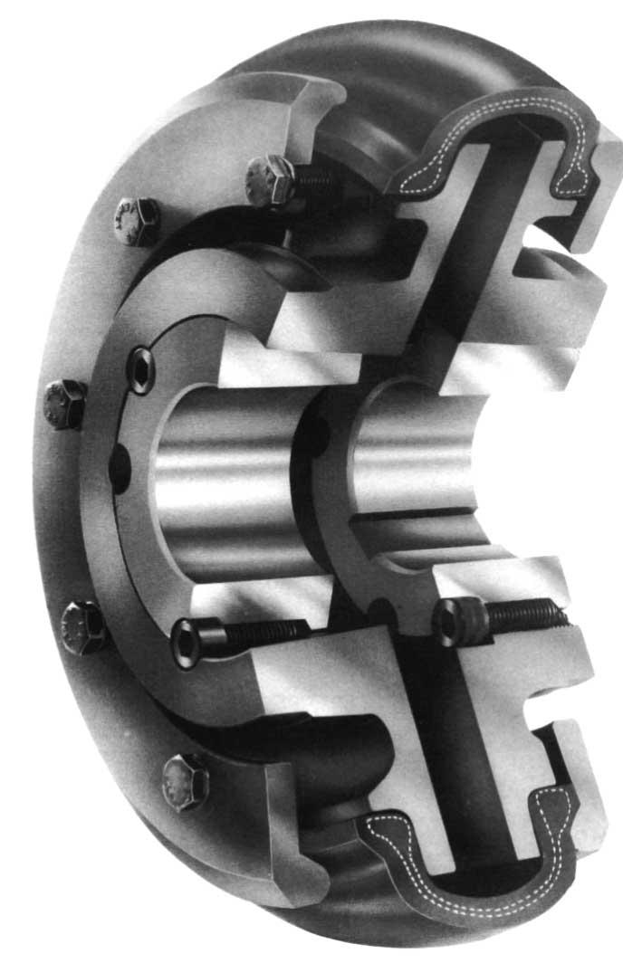
4 HRC Couplings HRC Couplings offer a range of hub and element selection to coupling. They allow for incidental misalignment, absorb shock loads and dampen out small amplitude vibrations. They are offered in both Pilot bore, Finished bore, and Taper bushed with both face and hub mount, meet the demand for a low cost, general purpose spacer type flexible. 1
5 HRC Couplings These semi-elastomeric couplings are designed for general purpose applications and permit quick and easy assembly by means of Taper bush. Outside diameters are fully machined to allow alignment by simple straight edge methods. Shaft connection is "fail safe" due to interacting jaw design. SELECTION (a) Service Factor Determine appropriate Service Factor from table below. (b) Design Power Multiply running power of driven machinery by the service factor. This gives the design power which is used as a basis for coupling selection. (c) Coupling Size Refer to Power Ratings table below and read across from the appropriate speed until a power greater than the design power is found. The size of coupling is given at the head of that column. (d) Bore Size From Dimensions table check that the required bores can be accommodated. EXAMPLE A shaft coupling is required to transmit 0kW between a 1200 rev/min diesel engine and a hoist running over 16hrs/day. Engine shaft is 0mm and the hoist shaft is 5mm. (a) Service Factor The appropriate Service Factor is 2,5. (b) Design Power Design power 0 x 2,5 = 15kW. (c) Coupling Size Reading across from 1200 rev/min in the speed column of Power Ratings table below, 251kW is the first power to exceed the required 15kW (design power). The size of the coupling at the head of this column is 230. (d) Bore Size The Dimensions table shows that both shaft diameters are within the bore range available. SERVICE FACTORS SPECIAL CASES Type of Driving Unit For application where substantial shock, vibration and torque fluctuation occur, Electric Motors Internal Combustion Engines and for reciprocating machines e.g. internal combustion engines, piston type Steam Turbines Steam Engines pumps and compressors, refer to us with full machine details for torsional analysis. Water Turbines Hours per day duty Hours per day duty over 8 over 8 8 and to 16 over 8 and to 16 over Driven Machine Class under inclusive 16 under inclusive 16 UNIFORM Agitators, Brewing machinery, Centrifugal blowers, Centrifugal compressors+, Conveyors, Centrifugal fans and pumps, Generators, Sewage disposal equipment. MODERATE SHOCK* Clay working machinery, crane hoists, Laundry machinery, Wood working machinery, Machine tools, Rotary mills, Paper mill machinery, Textile machinery, Non-uniformly loaded centrifugal pumps. HEAVY SHOCK* Reciprocating conveyors, Crushers, Shakers, Metal mills, Rubber machinery (Banbury mixers and mills), Reciprocating compressors, Welding sets. 1,00 1,60 2,50 1,12 1,80 2,80 1,25 2,00 3,12 1,25 2,00 3,12 1,40 2,24 3,55 1,60 2,50 4,00 * It is recommended that keys (with top clearance if in Taper bushes) are fitted for applications where load fluctuation is expected. + For Centrifugal Compressors multiply Service Factor by an additional 1,15. 2
6 HRC Couplings POWER RATINGS (Kw) Coupling Size Speed rev/min Nominal Torque (Nm) Max Torque (Nm) 0,33 0,66 1,32 1,98 2,3 2,65 3,1 3,96 4,5 5,28 5,94 6,60,26,92 8,58 9,50 9,90 11,90 31,50 2,00 0,84 1,68 3,35 5,03 6,03 6,0 8,04 10,10 12,10 13,40 15,10 16,80 18,40 20,10 21,80 24,10 25,10 30,10 80,00 180,00 1,68 3,35 6,0 10,10 12,10 13,40 16,10 20,10 24,10 26,80 30,20 33,50 36,90 40,20 43,60 48,30 50,30 60,30 160,00 360,00 3,30 6,60 13,20 19,80 23,80 26,40 31,0 39,60 4,50 52,80 59,40 66,00 2,60 9,20 85,80 95,00 99,00 118,00 315,00 20,00 6,28 12,60 25,10 3,0 45,20 50,30 60,30 5,40 90,50 101,00 113,00 126,00 138,00 151,00 163,00 181,00 188,00 226,00 600, ,00 9,95 19,90 39,80 59,0 1,60 9,60 95,50 119,00 143,00 159,00 19,00 199,00 219,00 239,00 259,00 286,00 298,00 950, , ,90 83,80 126,00 151,00 168,00 201,00 251,00 302,00 335,00 3,00 419,00 461,00 503,00 545, , ,00 33,00 65,00 132,00 198,00 238,00 264,00 31,00 396,00 45,00 528,00 594,00 660,00 26, ,00 200,00 Fire Resistant/Anti-Static (F.R.A.S.) inserts are available to special order. For speeds below 100 rev/min and intermediate speeds use nominal torque ratings. *Maximum coupling speeds are calculated using an allowable peripheral speed for the hub material. For selection of smaller sizes with speeds in excess of 3600 rev/min - Consult your dealer 3
7 HRC Couplings B FLANGE H FLANGE F FLANGE ASSEMBLED LENGTH PHYSICAL DIMENSIONS AND CHARACTERISTICS Common Dimensions Type F&H Type B Max. Bore Bore Dia. Bush Pilot Screw Size OD H E F+ G size MM Inches C D J+ Max. H9 over key C D ,0 85,0 112,0 130,0 150,0 180,0 225,0 25,0 60,0 0,0 100,0 105,0 115,0 125,0 155,0 206,0 31,0 32,0 45,0 50,0 62,0,0 99,0 119,0 25,0 30,5 45,0 54,0 61,0 4,0 85,5 105,5 18,0 22,5 29,0 36,0 40,0 49,0 59,5 4, ,000 1,125 1,625 1,625 2,000 2,500 3,000 4,000 + 'J ' is the wrench clearance required for tightening/loosening the bush on the shaft. A shortened wrench will allow this dimension to be reduced. + F, refers to combinations of flanges: FF, FH, HH, FB, HB, BB. Bore limits H unless specified otherwise. ASSEMBLED Assembled Length (L*) Dynamic Maximum Nominal Comprising Flange Types Mass Inertia Mr2 Stiffness Misalignment Torque (kg) (kgm2) (Nm) (Nm) Size FF,FH,HH FB,HB BB Parallel Axial ,0 69,5 82,0 89,0 10,0 142,0 164,5 20,5 65,0 6,0 100,5 110,0 129,5 165,5 202,0 246,5 65,0 82,5 119,0 131,0 152,0 189,0 239,5 285,5 1,00 1,1 5,00 5,46,11 16,60 26,00 50,00 0, , , ,0080 0, , , , ,3 0,3 0,3 0,4 0,4 0,4 0,5 0,5 +0,2 +0,5 +0,6 +0,8 + +1,1 +1,3 +1, Dimensions in millimeters unless otherwise specified. All HRC Elements have an angular misalignment capacity of up to 1º. Mass is for an FF, FH or HH coupling with mid range Taper Bushes. 20,0 19,5 18,5 18,0 23,5 34,5 39,5 51,0 23,5 23,5 26,5 26,5 33,5 46,5 52,5 66,5 29,0 29,0 38,0 38,0 42,0 48,0 55,0 6, M 6 M 6 M10 M10 M10 M10 M12 M16 20,0 26,0 3,0 39,0 46,0 58,0,0 90,0 25,8 30,0 45,3 4,5 60,0 0,0 90,0 105,5 ORDERING CODES Standard FRAS Type B Element Element Size Type F Type H Unbored Tempr.-40ºC/+100ºC Tempr.-20ºC/+80ºC HRC00F HRC090F HRC110F HRC130F HRC150F HRC180F HRC230F HRC280F HRC00H HRC090H HRC110H HRC130H HRC150H HRC180H HRC230H HRC280H 4 HRC00B HRC090B HRC110B HRC130B HRC150B HRC180B HRC230B HRC280B Note: For details of HRC couplings suitable for application to drives involving SAE engine flywheels, consult your dealer. Type B flanges can be supplied finished bored, with keyway if required. HRC00NA HRC090NA HRC110NA HRC130NA HRC150NA HRC180NA HRC230NA HRC280NA HRC00FR HRC090FR HRC110FR HRC130FR HRC150FR HRC180FR HRC230FR HRC280FR


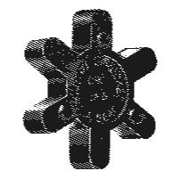
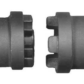
8 Flexible Jaw Couplings We Offer The Universal - Completely Interchangeable Jaw Coupling > No Lubrication > Easy Installation > No Metal to Metal Contact > Resistant to oil, dirt, sand, moisture, grease > Easy inspection of load carrying Spider > Flexibility of angular or parallel misalignment of shafts by Bruna-N Spider member permits smooth Power Transmission SHOULDER JAW A SERIES SHOULDER JAW A SERIES (ASSEMBLY) 5
9 Flexible Jaw Couplings Jaw Couplings offer a range of hub and element variants to meet the demand for low cost, general purpose and spacer type flexible couplings. They cater for incidental misalignment, absorb shock loads and damp out small amplitude vibrations. HUBS & SPACERS L (2 HUBS PLUS SPIDER ELEMENT) SW (2 HUBS PLUS SPIDER ELEMENT) dbse 100mm or 140mm RRS (2 HUBS PLUS SW RING KIT PLUS RRS SPACER KIT) DIMENSIONS: L, SW AND RRS B OD OD 1 Size L E H G Pilot Max SX QF Dimensions in millimeters unless otherwise specified. + Mass of complete L or SW type with pilot bore hubs Bored or bored and keywayed hubs can be supplied. Hub material is high grade cast iron. Spacer material is aluminum. Set Screw Approx + mass (kg) Max Speed (rpm) 035 3,20 9,5 15,9 20,6 6, 15,9, , , ,5 6,5 M6, , ,5 M6, , , ,5 9,0 M6, , , M6 2, , ,0 M8, , ,0 M8 1, , ,0 M10 3, , ,0 M10 5, , ,0 M12, , ,0 M12 8, dbse = distance between shaft ends *Bored or bored and keywayed hubs can be supplied in L and SW styles. Bores are to ISO 268 H tolerance (BS 4500 ; 1969). Keyways are to BS 4235 for metric bores and to BS 46 Pt 1 : 1958 for Imperial bores. 6


10 Flexible Jaw Couplings Jaw Coupling Selection Procedure A. Determine Service Factor by Matching Driven Unit with Prime Mover in Service Factor Guide. B. Multiply Service Factor by Driven Unit or Motor Kw. to Obtain Adjusted Kw. C. Select Flexible Coupling with Kw. Capacity Equal to or Greater than Adjusted Kw. Service Factor Guide Prime Mover Electric Motor or Gasoline or Diesel Gasoline or Diesel Driven Unit (Machinery) Steam Turbine Engine, 6 or More Cyl. Engine, Less Than 6 Cyl. Light: Uniform or steady load never exceeding horsepower rating, infrequent starting. Agitators, Blowers, Conveyors, Evaporators, Fans, Generators, Centrifugal Pumps, Stokers 1,0 1,5 2,0 Moderate: Heavy inertia, moderate shock, frequent starting; peak loads do not exceed 125 per cent average horsepower. Uneven load. Beaters, Rotary Pumps and Compressors, Cranes, Elevators, Mine and Propeller Fans, Generators, Pulp Grinders, Hoists, Kilns, Machine Tools, 1,5 2,0 2,5 Mixers, Gear Pumps, Woodworking Machines Heavy: Heavy shock conditions or frequent reversing. Peak loads do not exceed 150 per cent average horsepower. Uneven load. Reciprocating Pumps and Compressors, Crushers, Freight and Passenger Elevators, Mills (Hammer, Ball, Rolling, Turf, Flour), Vibrating Screens, Winches, Wire Drawing Machines, Punches, Shears 2,0 2,5 3,0 BORE TOLERANCES: = H L (Universal Series) Torque and Kilowatt Ratings Torque Rating Bruna-N Max. Weight (kg) Catalog Nm. Kilowatt Capacity at Various RPM Bore (Each) Number Bruna-N Hytrel * * 0,46,005,01,04,05,05,0 0,1,14 0,18 9,5, ,51 10,,03,11,26,35,45,53, 1,05 1,3 15,9, , 14,2,06,16,43,58,63,8,9 1,3 2,1 19,1, ,94 2,3,125,29,90 1,20 1,16 1,80 1, 3,61 4,51 22,2, ,6 4,5,201,49 1,44 1,93 1,9 2,89 3,0 5,8,22 28,6, ,8 64,1,2,6 1,95 2,59 2, 3,89 4,0,8 9,3 28,6, ,4 141,0,58 1,5 4,18 5,58 5,9 8,36 8,9 16, ,9, ,0 256,2 1,10 2,,94 10,59 10, 15,88 16,1 31, 39,1 41,3 1, ,0 405, 1,50 4,3 11,23 14,98 1,0 22,35 25,5 44,0 51,0 4,6 2, ,0 512,5 2,01 5,4 15,0 20,09 21,5 30,14 32,2 60,28 64,4 54,0 3, ,0 68, 2,6 8,1 21,09 28,13 32,2 41,40 48,3 82,80 96,6 66, 5,44 NOTE: Above Kw. capacities are for Bruna-N rubber spider and service factor of one. When Hytrel spider is used multiply capacities by three. * Available From U.S.A. Only.
 Bruna-N Hytrel* Coupling Bruna-N Hytrel SRL035 SHL035 ML035,004,004 SRL050 SHL050 M 050 MS 050,006,006 SRL00 SHL00 ML00 MS 00,008,008 SRL05 SHL05 ML05 MS 05,01,01 SRL090 SHL090 ML or")
11 Flexible Jaw Couplings COUPLING HALF SPIDER COUPLING HALF Spiders Bruna-N (Rubber) and Hytrel Catalog Number Accommodates Net Weight (Kg.) Bruna-N Hytrel* Coupling Bruna-N Hytrel SRL035 SHL035 ML035,004,004 SRL050 SHL050 M 050 MS 050,006,006 SRL00 SHL00 ML00 MS 00,008,008 SRL05 SHL05 ML05 MS 05,01,01 SRL090 SHL090 ML or MS ,02,02 SRL099 SHL099 ML or MS ,03,03 SRL110 SHL110 ML110 MS110,06,06 SRL150 SHL150 M150 MS150,10,10 SRL190 SHL190 ML190 MS190,12,12 SRL225 SHL225 ML225 MS225,19,19 Urethane spiders available. Please consult factory. *Available From U.S.A Only. Spiders Urethan and Bronze * Catalog Number Accommodates Net Weight (Kg.) Urethane Bronze H Coupling Urethane Bronze SUL035 ML 035,004 SUL050 ML050 MS050,006 SUL00 ML00 MS00,008 SUL05 ML05 MS05,01 SUL090 ML or MS ,02 SUL099 ML or MS ,03 SUL110 ML110 MS110,06 SUL150 ML150 MS150,10 SUL190 ML190 MS190,12 SUL225 ML225 MS225,19 Bronze spiders available as Made to Order. Coupling Selection Chart for 50 Hz Nema Motor Frames Based on Bruna-N (Rubber) Spider Max. Kilowatt RPM Shaft ISO Coupling Diameter Standards Size M S ML M S ML M S ML 9, ,4 0,4 0, 0,6 1,5 1,1 12, ,4 0,4 0, 0,6 1,5 1,1 15,9 56,56 H 050 0,4 0,4 0, 0,6 1,5 1,1 19, , 0,6 1,1 0, 2,2 1,5 22,2 56HZ, 143T, 145T 05 1,5 0, 2,2 1,5 5,6 2,2 182, ,2 1,5 3, 2,2,5 5,6 28,6 182T, 184T, ,2 2,2 3, 3,,5, ,6 3,,5 5,6 18,6 11,2 34,9 213T, 215T, 245U, 256U 100 5,6 5,6,5,5 18,6 14,9 41,3 254T, 256T, 248U, 286U ,2,5 18,6 14,9 3,3 29,8 4,6 284T, 286T, 324U, 326U, 326TS ,4 14,9 29,8 22,4 55,9 44, 54,0 324T, 326T, 364U, 365U ,8 18,6 44, 29,8 93,2 55,9 60,3 364T, 365T ,8 55,9 44, 111,9 4,6 NOTE: Coupling Sizes are based on the rated torque, max. bore and a have a service factor of 1,0. Dimensions in millimeters unless otherwise specified. * When Using Hytrel or Bronze spider multiply above Kw ratings by 3. When using Urethane spider multiply above Kw ratings by 1,5. 8
12 Flexible Jaw Couplings L Type Couplings L Type couplings range in size from 035 to 225. The coupling design provides for a collar to be attached to our hub shielding the snap wrap spider. Ordering requires selecting Item (UPC) numbers for one standard L type hub (without collar attachment), one standard snap wrap centre insert and one collar with screws. Standard Bore and Keyway Chart Bore Keyway mm mm No KW X 5 No KW X X 6 No KW X X No KW X X X 8 No KW X X X X 9 3 x 1,4 X X X 10 No KW X X X 10 3 x 1,4 X X X X 11 4 x 1,8 X X X X 12 No KW X X X 12 4 x 1,8 X X X X X X 14 No KW X X X X 14 5 x 2,3 X X X X X X X 15 No KW X X X X X 15 5 x 2,3 X X X X X X X 16 5 x 2,3 X X X X X X X X X 1 5 x 2,3 X X X X X X 18 6 x 2,8 X X X X X X X 19 No KW X X 19 6 x 2,8 X X X X X X X X X 20 6 x 2,8 X X X X X X X X 22 6 x 2,8 X X X X X X X 24 8 x 3,3 X X X X X X X 25 8 x 3,3 X X X X X X X 28 No KW X X 28 8 x 3,3 X X X X X X 30 8 x 3,3 X X X X X X 32 No KW X X X x 3,3 X X X X X 35 No KW X X X x 3,3 X X X X X x 3,3 X X X X x 3,3 X X X X x 3,3 X X X X x 3,8 X X X 48 No KW X x 3,8 X X X 50 No KW X X x 3,8 X X 55 No KW X X x 4,3 X X 60 No KW X x 4,4 X 65 No KW x 4,4 X 0 20 x 4,9 * Imperial sizes also available. Please consult your SKF Distributor. 9
13 Flexible Jaw Couplings ELEMENTS Type Temperature Range (ºC) Max Misalignment Ang Par. (MM) Power Factor Nitrile (Spider) Nitrile (QF) Urethane Hytrel -40 to to to 0-50 to th digit = Alpha character for coupling size 0,38 0,38 0,38 0, ,5 3 * SELECTION a) Find Service Factor for application from table right. b) Multiply normal running power by Service Factor. c) Select a standard nitrile element coupling size from Power Ratings table below by reading across from the appropriate speed until a power equal to or greater than the design power is found. Coupling size is at the head of the column. d) For alternative elements multiply the design power from step (b) by the Element Power Factor in table above and repeat step (c) with the new design power. e) For speeds other than those listed use the nominal torque ratings from the Power Ratings table below. SERVICE FACTORS Required Torque (Nm) = Design power (Kw) x 9555 Driven Load rev/min f) Check for the hub Dimensions tables that bore capacity is Uniform Load 1,0 adequate for the coupled shafts. Moderate Shock 1,5 g) Orders for complete couplings should give part numbers Heavy Shock 2,0 for hubs, elements and spacers separately. SPACERS AND QF RETAINING RINGS - CODES All codes first 4 digits: 968-4th digit: Alpha character for coupling size 5/6th digits: Spacer kit = 33; Retaining ring kit = 99 /8th digits: Retaining ring kit = 00; Spacer kit 100mm = 10; Spacer kit 140mm = 14 POWER RATINGS (kw) NITRILE ELEMENTS Prime Mover Electric Motor Speed Coupling Size (rev/min) ,03 0,06 0,12 0,20 0,2 0,58 1,10 1,56 2,09 2, ,26 0,43 0 1,44 1,95 4,18,94 11,23 15,0 21, ,35 0,58 1,20 1,93 2,59 5,58 10,59 14,98 20,09 28, ,53 0,8 1,80 2,89 3,89 8,36 15,88 22,46 30,14 42, ,05 1,3 3,61 5,8,8 16,3 31, 44,93 60,28 84, ,32 2,1 4,51,22 9, ,1 56,16 5,35 105,5 Nominal Torque (Nm) 3,51 5, 11,9 19,2 25,8 55, L hub RRS spacer kit (spacer + SW ring kit) SW ring kit L hub 10
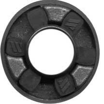
14 Tyre Couplings Flexible Tyre Highly resilient flexible tyre cushions shock loads, smoothing out load between driving and driven machines. Enables high levels of misalignment to be accommodated. Easy Installation Radially split tyre facilitates easy installation and removal without disturbing driving or driven shafts. Maintenance and Lubrication Lubrication No maintenance or lubrication is required, visual inspection is all that is necessary. Taper Flanges Made from high grade S.G. iron, versatile design enable easy positioning on the shafts. The clamping system prevents relative movement between flexible tyre and flange. Taper Bush Provides a wide range of bore diameters, and enables easy assembly to shafts. Tension Member Cross piled synthetic tension member enables torque to be transmitted in either direction. Elastomeric Compound Available in either natural rubber or fire-resistant and anti-static chloroprene. Provides the shape and damping of the tyre. 11
15 Tyre Couplings Tyre couplings provide all the desirable features of an ideal flexible coupling, including Taper Bush fixing. The Tyre Couplings is a torsionally elastic coupling offering versatility to designers and engineers with a choice of flange combinations to suit most applications. The flanges are available in either F (face) or H (hub) Taper Bush fitting or bored to size. With the addition of a spacer flange the coupling can be used to accommodate standard distance between shaft ends and facilitate pump maintenance. Tyre couplings can accommodate simultaneous maximum misalignment in all planes without imposing undue loads on adjacent bearings and the excellent shock-absorbing properties of the flexible tyre reduce vibration and torsional oscillation. Tyres are available in natural rubber compounds for use in ambient temperatures between -50 C and +50 C. Chloroprene rubber compounds are available for use in adverse operating conditions (e.g. oil or grease contamination) and can be used in temperatures of -15 C to +0 C. The chloroprene component should also be used when fire-resistance and anti-static (F.R.A.S.) properties are required. SELECTION (a) Service Factor Determine the required Service Factor from table below. (b) Design Power Multiply the normal running power by the service factor. This gives the design power which is used as a basis for selecting the coupling. (c) Coupling Size Refer to Power Ratings table and from the appropriate speed read across until a power greater than that required in step (b) is found. The size of coupling required is given at the head of that column. (d) Bore Size Check for Dimensions table that chosen flanges can accommodate required bores. SERVICE FACTORS SPECIAL CASES For applications where substantial shock, vibration and torque fluctuations occur, and for reciprocating machines (e.g. internal combustion engines, piston pumps and compressors) refer to us with full machine details for analysis. Type of Driven Machine EXAMPLE A Tyre coupling is required to transmit 50kW from an A.C. electric motor which runs at 1440 rev/min to a rotary screen for 10 hours per day. The motor shaft is 60mm diameter and the screen shaft is 55mm diameter. Taper Bush is required. (a) Service Factor The appropriate service factor is 1,3. (b) Design Power Design Power = 50 x 1,3 = 65kW. (c) Coupling Size By reading across from 1440 rev/min in the power ratings table the first power figure to exceed the required 65kW in step(b) is 5,4kW. The size of Tyre coupling is F90. (d) Bore Size By referring to the dimensions table it can be seen that both shaft diameters fall within the bore range available. Electric Motors Steam Turbines Hours per day duty Type of Driven Unit Internal Combustion Engines Steam Engines Water Turbines Hours per day duty 10 and over 10 over 10 and over 10 over under to 16 incl. 16 under to 16 incl. 16 CLASS 1 Agitators, Brewing machinery, Centrifugal compressors and pumps. Belt conveyors, Dynamometers, Lineshafts, Fans up to,5kw. Blowers and exhausters (except positive displacement), Generators. CLASS 2* Clay working machinery, General machine tools, paper mill beaters and winders, Rotary pumps, Rubber extruders, Rotary screens, Textile machinery, Marine propellers and Fans over,5kw. CLASS 3* Bucket elevators, Cooling tower fans, Piston compressors and pumps, Foundry machinery, Metal presses, Paper mill calenders, Hammer mills, Presses and pulp grinders, Rubber calenders, Pulverizers and Positive displacement blowers. CLASS 4* Reciprocating conveyors, Gyratory crushers, Mills (ball, pebble and rod), Rubber machinery (Banbury mixers and mills) and Vibratory screens. 0,8 1,3 1,8 2,3 1,4 1,9 2,4 1,0 1,5 2,0 2,5 1,3 1,8 2,3 2,8 1,4 1,9 2,4 2,9 1,5 2,0 2,5 3,0 *It is recommended that keys (with top clearance if in Taper bushes) are fitted on application where load function is expected. + Couplings for use with internal combustion engines may require special consideration, such as a flywheel configuration. 12
16 Tyre Couplings POWER RATINGS (kw) Speed ,25 0,50 0,5 1,01 1,26 1,51 1,6 1,81 2,01 2,26 2,41 2,51 3,02 3,52 3,62 4,02 4,52 5,03 5,53 6,03 6,53,04,24,54 9,05 0,69 1,38 2,0 2,6 3,46 4,15 4,84 4,98 5,53 6,22 6,63 6,91 8,29 9,68 9,95 11,1 12,4 13,8 15,2 16,6 18,0 19,4 19,9 20, 24,9 1,33 2,66 3,99 5,32 6,65,98 9,31 9,5 10,6 12,0 12,8 13,3 16,0 18,6 19,1 21,3 23,9 26,6 29,3 31,9 34,6 3,2 38,3 39,9 4,9 2,62 5,24,85 10,5 13,1 15, 18,3 18,8 2 23,6 25,1 26,2 31,4 36,6 3, 41,9 4,1 52,4 5,6 62,8 68,1 3,3 5,4 8,5 94,2 3,93,85 11,8 15, 19,6 23,6 2,5 28,3 31,4 35,3 3, 39,3 4,1 55,0 56,5 62,8 0, 8,5 86,4 94, ,24 10,5 15, 2 26,2 31,4 36,6 3, 41,9 4,1 50,3 52,4 62,8 3,3 5,4 83,8 94,2 105, PHYSICAL CHARACTERISTICS - FLEXIBLE TYRES,0 14,1 21,2 28,3 35,3 42,4 49,5 5 56,5 63,6 6,9 0, 84,9 99, Coupling Size rev/min F040 F050 F060 F00 F080 F090 F100 F110 F120 F140 F160 F180 F200 F220 F250 9,16 18,3 2,5 36,6 45,8 55,0 64,1 66,0 3,3 82,5 88,0 91, ,9 2,9 41,8 55, 69,6 83,6 9, ,3 48, 3,0 9, ,5 9, , , The figures in heavier type are for standard motor speeds. All these power ratings are calculated at constant torque. For speeds below 100 rev/min and intermediate speeds use nominal torque ratings. Coupling Size Characteristics F040 F050 F060 F00 F080 F090 F100 F110 F120 F140 F160 F180 F200 F220 F250 Maximum speed rev/min Nominal Torque Nm TKN Maximum Torque Nm TK MAX Torsional Stiffness Nm/ Max, parallel misalignment mm Maximum end float mm Approximate mass, kg Alternating Torque 10Hz TKW Resonance Factor V Damping Coefficient ,1 1,3 0, ,3 1, 0, ,6 2,0 0, ,9 2,3 0, ,1 2,6 1, ,4 3,0 1, ,6 3,3 1, ,9 3, 1, ,2 4,0 2, , 4,6 2, ,2 5,3 3, ,8 6,0, ,3 6,6 8, ,8, ,6 8, Maximum torque figures should be regarded as short duration overload ratings for use in such circumstances as direct-on-line starting. All flexible tyres have an angular misalignment capacity up to 4 FLEXIBLE TYRE CODE NUMBERS Unless otherwise specified Flexible tyres will be supplied in a natural rubber compound which is suitable for operation in temperatures -50 C to +50 C. A chloroprene compound is available which is Fire Resistant and Anti-Static (F.R.A.S.) and has greater resistance to heat and oil. This is suitable for operation in temperatures -15 C to +0 C. For temperatures outside these ranges - consult your dealer. Tyre Part Numbers Size Natural F.R.A.S. F040 F050 F060 F00 F080 F090 F100 F110 F120 F140 F160 F180 F200 F220 F250 F040NA F050NA F060NA F00NA F080NA F090NA F100NA F110NA F120NA F140NA F160NA F180NA F200NA F220NA F250NA 13 F040FR F050FR F060FR F00FR F080FR F090FR F100FR F110FR F120FR F140FR F160FR F180FR F200FR F220FR F250FR BACK STOP/SAFETY DOGS POSITIVE DRIVE APPLICATIONS In the unlikely event of the failure of the flexible tyre, the drive can be maintained with the interaction of fitted back stop/ safety dogs. Safety dogs are available for coupling sizes F0 to F250 and should be fitted when it is essential to avoid run back, e.g. cranes, hoists, lifts, elevators, inclined conveyors, etc. Consult local distributor for details.

17 Tyre Couplings Whatever Your Need For Couplings We Have Them SIZES F SIZES F SIZES F (REVERSIBLE) 14
18 Tyre Couplings - Dimensions SIZES TYPE B TYPE F TYPE H SIZES (REVERSIBLE) TYPE FH TYPE FH SIZES TYPE B TYPE F TYPE H 15
19 Tyre Couplings - Dimensions DIMENSIONS OF TYRE COUPLING FLANGES TYPES B, F, H & FH Max. Types F & H Type B Bore Part Screw Number Size Type Bush (B) over O.D. FD H F G* M* Mass* Inertia* No. Metric L E R* L E Key (kg) (kgm2) F040B F040 B M ,8,000 F040F F040 F ,8 4 F040H F040 H ,8,000 F050B F050 B M ,5 1,2 4 F050F F050 F , ,5 1,2,000 F050H F050 H , ,5 1,2 4 F060B F060 B M ,5 2,0,0011 F060F F060 F , ,5 2,0 5 F060H F060 H , ,5 2,0,0011 F00B F00 B M ,5 3,1 5 F00F F00 F , ,5 3,1,0011 F00H F00 H , ,5 3,0 5 F00FH F00 FH M , ,5 F080B F080 B M ,5 4,9,0052 F080F F080 F , ,5 4,9,0052 F080H F080 H , ,5 4,6,0052 F080FH F080 FH , M , ,5 F090B F090 B 5 62,5 49 M ,5,1 0,009 F090F F090 F , ,5,0 0,009 F090H F090 H , ,5,0 0,009 F090FH F090 FH , M , ,5 F100B F100 B 80 69,5 56 M ,5 9,9 0,018 F100F F100 F , ,5 9,9 0,018 F100H F100 H , ,5 9,4 0,01 F100FH F100 FH , M , ,5 F110B F110 B 90 5,5 63 M ,5 12,5 0,032 F110F F110 F , ,5 11, 0,031 F110H F110 H , ,5 11, 0,031 F110FH F110 FH , M , ,5 F120B F120 B ,5 0 M ,5 16,9 0,055 F120F F120 F , ,5 16,5 0,055 F120H F120 H , ,5 15,9 0,054 F120FH F120 FH , M , ,5 F140B F140 B ,5 94 M , ,2 0,081 F140F F140 F , ,3 0,08 F140H F140 H , ,3 0,08 F160B F160 B M ,8 0,13 F160F F160 F ,5 0,13 F160H F160 H ,5 0,130 F180B F180 B M ,1 0,254 F180F F180 F ,2 0,255 F180H F180 H ,2 0,255 F200B F200 B M ,2 0,469 F200F F200 F ,6 0,380 F200H F200 H ,6 0,380 F220B F220 B ,5 12 M ,5 9,6 0,81 F220F F220 F , ,5 2,0 0,84 F220H F220 H , ,5 2,0 0,84 F250B F250 B ,5 132 M ,5 104,0 1,301 Dimensions in millimeters unless otherwise specified. * G is the amount by which clamping screws need to be withdrawn to release tyre. J is the wrench clearance to allow for tightening/loosening the bush on the shaft and the clamping screws on sizes F40, F50 and F60. The use of a shortened wrench will allow this dimension to be reduced. * M is half the distance between flanges, Shaft ends, although normally located twice M apart, can protect beyond the flanges as shown. In this event allow sufficient space between for end float and misalignment. Mass and interia figures are for single flange with mid range bore and included clamping ring, screws and washers and half tyre. For pilot bore ëbí flange code is listed. Flanges are also available finish bored with keyway if required. Bore must be specified on order. #Note: On sizes F00, 080, 100 and 120 the 'F' direction bush is larger than that in the 'H' direction. 16
, Spacer couplings are primarily designed for standard distance between shaft and dimensions 100, 140 and 180mm.")
20 Tyre Spacer Couplings DISTANCE BETWEEN SHAFT ENDS F040 F050 F060 F00 F080 F090 F100 F110 F120 F140 Comprising a Tyre coupling size (F40 - F140) complete with a spacer flange designed for use on applications where it is an advantage to be able to move either shaft axially without disturbing the driving or driven machine (e.g. centrifugal pump rotors), Spacer couplings are primarily designed for standard distance between shaft and dimensions 100, 140 and 180mm. Distance between Shaft Ends (MM) SM12 S M16 SM25 SM30 SM35 Size 80(100) Min Max Min Max Min Max Min Max Min Max Min Max Min Max Min Max Min Max Min Max Note: Alternative distances between shaft ends may be accommodated SELECTION 1. Select a suitable size of Tyre coupling using method shown on page C-6. Read down the first column in table below and locate the size of coupling desired. 2. Read across until the required distance between shaft ends can be accommodated. 3. Note the required spacer coupling designation at head of column. 4. Check from the Spacer Coupling Dimensions table below that the selected spacer/coupling combination can accommodate the machine shaft size SPACER COUPLING DIMENSIONS DBSE Spacer Max. Bore Tyre Max. Bore Spacer Nom Tyre Bush Coupling DBSE Coupling Size mm Inch Bush Size mm Inch A B C D E F G H J K L M S T SM12 80 F , SM F , SM F , SM F , SM F , , SM F , , SM F , , SM F , , SM F , SM F , SM F , SM F , , SM F , , SM F , , SM F , , SM F , , SM F SM F SM F SM F SM F SM F SM F SM F Note: Larger sizes of spacer couplings are available. 1 * F040 'B' Flange must be used to fit spacer shaft. 'F' Flange must be used to fit spacer shaft. DBSE- distance between shaft ends.
21 Tyre Couplings - Installation Instructions NOTE: Satisfactory performance depends on correct installation and maintenance. Under no circumstances should any machine be started unless the coupling and associated machine is completely assembled. All instructions in this manual should therefore be followed accurately. 1. Thoroughly clean all components, paying particular attention to the removal of the protective coating in flange bores and on bushes. 2. Fit flanges to the shafts after placing the external clamp rings on the shafts. (Where Taper flanges are used, see separate fitting instructions supplied with the Taper Bushes.) Locate flanges so that dimension M is obtained (see paragraph 3). Flanges with internal clamping rings should then have the clamping rings fitted, engaging only two or three of the threads of the screws at this time. 3. Bring shafts into line until dimension M is obtained (table 2). If shaft end float is to occur, locate the shafts at mid-position of end float when checking dimension M. Note the shafts ends may project beyond the faces of the flanges if required. In this event, allow sufficient space between shaft ends for end float and mis-alignment. Flanges should be fitted flush with the end of the shaft when used with Mill-Motor flanges. 4. Check parallel alignment by laying a straight edge across the flanges at several positions around the circumference. Check angular alignment by measuring gap between flanges at several positions around the circumference. It is desirable to align the coupling as accurately as possible, particularly on high speed applications. 5. Open out tyre and fit over coupling flanges ensuring that the tyre beads seat properly on the flanges and/or clamping rings. To ensure proper seating, it may be necessary to strike the outside diameter of the tyre with a small mallet. When seated there should be a gap between the ends of the tyre as shown in Table 1. TABLE 1 Coupling Size Tyre Gap mm F040 to F060 2 F00 to F Tighten clamping ring screws alternately and evenly (half turn at a time) working round each flange until the required screw torque is achieved (table 2). 3 F140 and F160 5 F180 to F250 6 Internal Clamping Ring M Seating Dia. for Tyre External Clamping Ring M Seating Dia. for Tyre Flange Flange TABLE 2 Coupling Size F040 F050 F060 F00 F080 F090 F100 F110 F120 F140 F160 F180 F200 F220 F250 M MM Screw Size M6 M6 M6 M8 M8 M10 M10 M10 M12 M12 M16 M16 M16 M20 M20 Clamping Screw Nm Torque 18
22 Tyre Couplings Flexible Tyre couplings smoothly transmit power while compensating for shaft misalignment to 4, parallel misalignment to 3,2 and end float to,9. The two piece flange design provides quick and easy installation and the elastomeric element absorbs shock and torsional vibration through a wide temperature range. Quick Selection Procedure 1. Select the proper service factor from Chart Determine Design Kw by multiplying the Service Factor and the Drive Kw. 3. Locate the intercept of Shaft Speed and Design Kw from Chart2. 4. Order per coupling: (2) bushings, (2) flange assemblies, (1) flexible tire element. Chart 1 - Service Factors Application Factor Application Factor Application Factor Application Factor Application Factor AGITATORS Paddle or Propeller (Vert. or Horiz.), Screw... 1,0 BREWING AND DISTILLING Bottling Machinery, Brew Kettle, Cooker (Cont. Duty), Mash Tub... 1,0 Scale Hopper Frequent Starting Peaks... 1,5 CAN FILLING MACHINE... 1,0 CAR DUMPER... 1,5 CAR PULLER... 1,5 CLARIFIER... 1,0 CLASSIFIER... 1,0 CLAY-WORKING MACHINES Brick Press, Briquette Machine, Clay Working Machine, Pug Mill... 1,5 COMPRESSORS Lobe, Rotary... 2,0 Reciprocating** 1 cyl. single acting... 3,5 1 cyl. double acting... 3,0 2 cyl. single acting... 3,0 2 cyl. double acting... 2,5 3 cyl.or more single acting... 2,5 3 cyl. or more double acting... 2,0 CONVEYORS Apron, Assembly, Belt, Chain, Flight, Oven... 1,0 Reciprocating... 2,5 Screw... 1,0 CRANES AND HOISTS Main Hoist Medium Duty... 1,5 Main Hoist Heavy Duty... 2,0 Skip Hoist, Travel Motion, Trolley Motion, Slope... 1,5 CRUSHERS Cane... 2,0 Gyratory... 2,5 DREDGES Cable Reel, Conveyor... 1,5 Cutter Head Drive, Jog Drive... 2,5 Pump, Screen Drive, Stacker, Utility Winch... 1,5 DYNAMOMETER... 1,0 ELEVATORS Bucket, Freight... 2,0 EXCITER... 1,0 FANS Centrifugal... 1,0 Cooling Tower... 2,0 Large (Mine, etc.)... 1,5 Light... 1,0 Propeller (indoor)... 1,5 FOOD INDUSTRY Beet Slicer... 1,5 Cereal Cooker... 1,0 Dough Mixer, Meat Grinder... 1,5 GENERATORS Even Load... 1,0 Hoist or Railway Service... 1,5 Welder Load... 2,0 GRIZZLY... 2,0 KILN... 2,0 LAUNDRY MACHINES Tumbler, Washer... 2,0 LINE SHAFTS... Driving Processing Machinery... 1,0 Light... 1,0 LUMBER INDUSTRY Band Resaw, Circular Resaw... 1,5 Edger, Head Rig, Hog, Log Haul... 2,0 Planer... 1,5 Rolls Non-Reversing... 1,5 Rolls Reversing... 2,0 Sawdust Conveyor... 1,0 Slab Conveyor, Sorting Table... 1,5 MACHINE TOOLS Auxiliary... 1,0 Main Drive, Notching Press, Planer (Reversing), Plate Planer, Punch Press... 1,5 Traverse... 1,0 METAL FORMING MACHINES Draw Bench Carriage, Main Drive, Extruder, Wire Drawing, Flattening Machine... 2,0 MILLS (Rotary Type) Ball or Pebble Direct or... 2,5 on LS Shaft Gear Reducer... 2,5 on HS Shaft Gear Reducer... 2,0 Dryer and Cooler... 1,5 Rod or Tube Direct or... 2,5 on LS Shaft Gear Reducer... 2,5 on HS Shaft Gear Reducer... 2,0 Tumbling Barrel... 1,5 MIXERS Concrete (Continuous or intermittent), Muller- Simpson type... 1,5 OIL INDUSTRY Chiller... 1,0 Oil Well Pumping (not over 150% peak torque)... 2,0 Paraffin Filter Press... 1,5 PAPER MILLS Agitator... 1,0 Barking Drum... 2,5 Beater and Pulper... 1,5 Bleacher... 1,0 Calender... 2,0 Chipper... 3,0 Couch, Cylinder, Dryer... 1,5 Felt Stretcher... 1,0 Fourdrinier... 1,5 Jordan... 2,0 Press... 2,0 Pulp Grinder... 2,0 Stock Chest... 1,5 Stock Pump Reciprocating... 2,0 Rotary... 1,5 Suction Roll... 2,0 Winder... 1,5 PARAFFIN FILTER PRESS... 1,5 PRINTING PRESS... 1,5 PROPELLER (Marine)... 1,5 PULVERIZERS Hammermill Light Duty... 1,5 Hammermill Heavy Duty.. 2,0 Hog... 2,0 Roller... 1,5 PUMPS Centrifugal... 1,0 Descaling, Gear Type... 1,5 Oil Well Pumping (not over 150% peak torque)... 2,0 Rotary other than gear... 1,5 Reciprocating 1 cyl. single acting... 2,5 1 cyl. double acting... 2,0 2 cyl. single acting... 2,0 2 cyl. double acting... 1,5 3 cyl. or more... 1,5 RUBBER INDUSTRY Banbury Mixer... 2,5 Calender... 2,0 Cracker, Mixing Mill, Plasticator... 2,5 Refiner, Sheeter, Tire Building Machine... 2,0 Tire and Tube Press Opener (Based on Peak Torque)... 1,0 Tuber and Strainer... 1,5 Warming Mill... 2,0 Washer... 2,5 SCREENS Air Washing... 1,0 Coal and Sand (Rotary)... 1,5 Vibrating... 2,5 Water... 1,0 SEWAGE DISPOSAL EQUIPMENT... 1,0 SHOVEL... 2,0 SHREDDER... 1,5 STEEL INDUSTRY Cold Mills Coiler (up or down)... 1,5 Strip, Temper... 2,0 Hot Mills Coiler (up or down), Edger Drive... 1,5 Feed Roll (Blooming), Roughing Mill Delivery (non-reversing), Sheet, Strip... 3,0 Rod Mill... 2,5 Soaking Pit Cover Drive... 3,0 STEERING GEAR... 1,0 STOKER... 1,0 TEXTILE MILLS Batcher... 1,0 Calender, Card Machine, Dry Can... 1,5 Dyeing Machinery... 1,0 Loom... 1,5 Mangel, Napper, Soaper... 1,0 Spinner, Tenter Frame... 1,5 WINDLASS... 1,5 WOODWORKING MACHINES.. 1,0 The service factors listed are intended only as a general guide for smooth power sources such as electric motors and steam turbines. Add 0,5 to factor for somewhat rougher power sources such as internal combustion engines of four or more cylinders, steam engines and water turbines. Where substantial shock occurs or starting or stopping is frequent as on some "inching" drives and on some reversing drives or where the power source is an internal combustion engine with less than four cylinders consult factory. Where torsional vibrations occur as in, for example, internal combustion engines or reciprocating compressors or pump applications, check the coupling for possible development of damaging large amplitude vibrations. ** Add 0,5 to factor if without flywheel. 19

23 Tyre Couplings Chart 2 - Size Selection SHAFT SPEED (RPM)


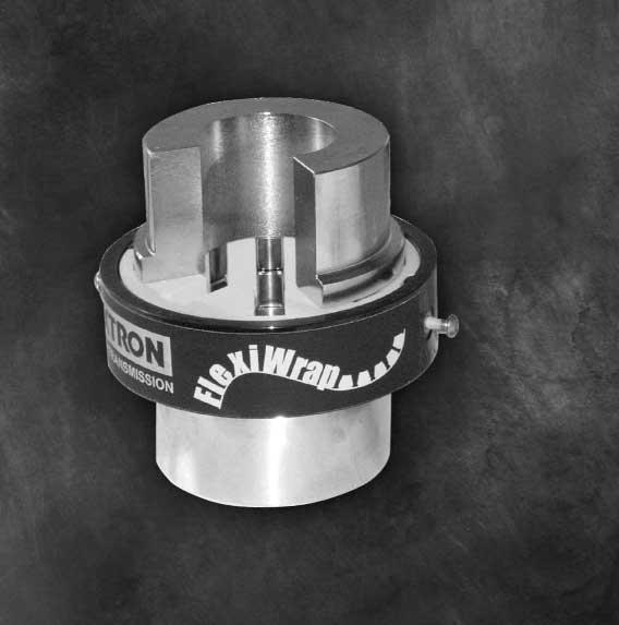
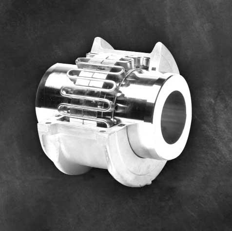
24 Textron Range Also available from SKF Distributor - The Textron Range of Couplings 21
25 Notes 22
26 Notes 23
27 Coupling Application Data Sheet State Other HRC Tyre L Chain
28 OPTIBELT Classical and Wedge V-belts Timing Belts Variable Speed Belts Ribbed Belts TEXTRON Cone Ring Couplings Grid Couplings Gear Couplings Flexiwrap Couplings REX Roller Chain British Standard American Standard Engineered Chain BENZLERS Shaft Mounted Speed Reducers Geared Motors Worm Boxes Screw Jacks Open Gearing Gearbox Re-furbishment AVAILABLE NATIONALLY THROUGH YOUR LOCAL SKF DISTRIBUTOR MELBOURNE 1-21 Stamford Road Oakleigh VIC 3166 Phone: (03) Fax: (03) ADELAIDE Unit 1 & 2, -9 Streiff Road Wingfield SA 5013 Phone: (08) Fax: (08) SKF STATE OFFICES SYDNEY 5 St. Hilliers Road Auburn NSW 2144 Phone: (02) Fax: (02) PERTH 95 Great Eastern Highway Rivervale WA 6103 Phone: (08) Fax: (08) BRISBANE 282 Beatty Road Archerfield QLD 4108 Phone: (0) Fax: (0) DISTRIBUTOR
Power Transmission Products. Maurey Couplings. Hi-Flex Tire Couplings Hi-Q Jaw Couplings Finished Bore Sleeve Couplings Rigid Bushed Sleeve Couplings
 Power Transmission Products Maurey Couplings Hi-Flex Tire Couplings Hi-Q Jaw Couplings Finished Bore Sleeve Couplings Rigid Bushed Sleeve Couplings Hi-Q Flexible Couplings R to enable full power transmission
Flexible Jaw Couplings
 Flexible Jaw Martin Offers The Martin Universal Completely Interchangeable No Lubrication asy Installation No Metal to Metal Contact asy inspection of load carrying Spider Flexibility of angular or parallel
(d) Bore Size Check from Dimensions table (page 112) that chosen flanges can accommodate required bores.
 Bore Size Check from Dimensions table (page 112) that chosen flanges can accommodate required bores.") Fenaflex Couplings The Fenaflex coupling is a highly flexible, torsionally elastic coupling offering versatility to designers and engineers with a choice of flange combinations to suit most applications.
Fenaflex Couplings The Fenaflex coupling is a highly flexible, torsionally elastic coupling offering versatility to designers and engineers with a choice of flange combinations to suit most applications.
DRIVE COUPLINGS DRIVE COUPLINGS
 DRIVE COUPLINGS Fenner shaft couplings range from highly resilient to totally rigid and are all precision manufactured using high quality ferrous materials and the latest polymer technology. Fenaflex tyre
Group 078
 1-078-080111 Group 078 EUROTEC TIRE COUPLINGS American Metric s eurotec tire couplings provide all the desirable features of an ideal flexible coupling, including Taper Lock installation. The eurotec tire
Gear Coupling. Applications
 Gear Coupling Applications Power Transformation Print & Paper Industries Gear Boxes Textile Industries Conveyors Pumps Compressors Process, Chemical & Pharmaceutical Industries Nylon Gear Couplings Nylon
Flange Flexible Couplings.
 Flange Flexible Couplings Coupling Selection Coupling Selection How to Select Standard Selection The Standard Selection may be used for engine driven, motor, or turbine applications. The following information
FLEXIBLE JAW COUPLINGS
 To order this part, call Lifco Hydraulics USA Toll Free at -800-92-849 Jaw Type Couplings USA Standard The Jaw Type Couplings from Vescor are offered in the industry s largest variety of stock bore/keyway
Size 1120, Bore Ø0.75" Size 1320, Bore Ø1.25" Size 1420, Bore Ø1.375" 3/4HP. Size 1320, Bore Ø1.25" Size 1320, Bore Ø1.25" Size 1633, Bore Ø2.
 Product Range Hollow Shaft Type Selections shaded in blue offer an increased service factor. Please refer to the gearmotor selection tables for specific unit service factor details. Nominal Ratio (:1)
Jaw Type. Overview. Jaw Type Couplings USA Standard Elastomer-in-Compression
 -1 Overview Jaw Type Couplings USA Standard Elastomer-in-Compression The Jaw Type couplings from Lovejoy are offered in the industry s largest variety of stock bore/keyway combinations. These couplings
TRANSMISSIONS. Mechanical Power Transmission
 TRANSMISSIONS Mechanical Power Transmission Dunlop BTL Ltd European Distribution Centre MPT House Brunswick Road Cobbs Wood Industrial Estate Ashford, Kent. UK TN23 1EL Contact us +44 (0)1233 663340 +44
Jaw Type JW JW-1. Polígono Indutrial O Rebullón s/n Mos - España -
 -1 Overview Couplings USA Standard Elastomer-in-Compression The couplings from Lovejoy are offered in the industry s largest variety of stock bore/keyway combinations. These couplings require no lubrication
Speed Reducers and Gearmotors
 and Gearmotors Table of Contents 1. General Information 2. How to Select...2.2 Configure a Model Number (Nomenclature)...2.4 AGMA Load Classifications...2.6...2.8 Single Reduction,,, Y3, Y5,...2.8 Single
L-Jaw Elastomeric Couplings
 L-Jaw Elastomeric Couplings F3 100% interchangeable with industry standard 3 Insert materials available 3 Hub materials available Large selection of sizes P-1686-TBW 4/16... TB Wood s 888-829-6637 F3-1
Jaw. In This Section:
 Jaw In This Section: L Type LC Type Al Type - Aluminum SS Type - Stainless RRS and RRSC Types - Spacer C and H Type - Medium / Heavy Duty RRC Type - Spacer www.lovejoy-inc.com 13-1 Jaw Safety Warning When
PRODUCT MANUAL TYRE-FLEX COUPLING (T,TO & RST)
") RATHI TRANSPOWER PVT. LTD. PUNE - INDIA PRODUCT MANUAL TYRE-FLEX COUPLING (T,TO & RST) R-PM-T-1/3-1/14 Page 1 INDEX CONTENTS PAGE Standard Features 3 At a Glance 3 TYRE-FLEX Family 3 Elastomer Information
RATHI TRANSPOWER PVT. LTD. PUNE - INDIA PRODUCT MANUAL TYRE-FLEX COUPLING (T,TO & RST) R-PM-T-1/3-1/14 Page 1 INDEX CONTENTS PAGE Standard Features 3 At a Glance 3 TYRE-FLEX Family 3 Elastomer Information
Specialty Couplings. Overview. Deltaflex Coupling Design Lovejoy offers maximum misalignment capacity with the Deltaflex coupling! SP-3.
 Overview Deltaflex Coupling Design Lovejoy offers maximum misalignment capacity with the Deltaflex coupling! The Deltaflex coupling is the real solution to installation, misalignment, and performance problems.
SURE-FLEX ELASTOMERIC COUPLINGS
 SECTION F1 SURE-FLEX ELASTOMERIC COUPLINGS Need No Lubrication, No Maintenance Quick, Easy Installation Clean, Quiet Performance TB WOOD S INCORPORATED Chambersburg, Pennsylvania 17201 T.B. WOOD S CANADA
Universal Joints. In This Section: D Type HD Type D Type Stainless NB (Needle Bearing) Type LOJ Type DD and DDX Type Universal Joint Boots
 Type LOJ Type DD and DDX Type Universal Joint Boots") JW Universal Joints In This Section: D Type HD Type D Type Stainless NB (Needle Bearing) Type LOJ Type DD and DDX Type Universal Joint Boots www.lovejoy-inc.com 329-1 JW Universal Joints Safety Warning
JW Universal Joints In This Section: D Type HD Type D Type Stainless NB (Needle Bearing) Type LOJ Type DD and DDX Type Universal Joint Boots www.lovejoy-inc.com 329-1 JW Universal Joints Safety Warning
SURE-FLEX ELASTOMERIC COUPLINGS
 SECTION F1 SURE-FLEX ELASTOMERIC COUPLINGS Need No Lubrication, No Maintenance Quick, Easy Installation Clean, Quiet Performance TB WOOD S INCORPORATED Chambersburg, Pennsylvania 17201 T.B. WOOD S CANADA
Mechanical. Flexible Couplings. Lowest Cost TOTAL Solution
 Mechanical FC Flexible Couplings Lowest Cost TOTAL Solution SECTION F1 SURE-FLEX ELASTOMERIC COUPLINGS Need No Lubrication, No Maintenance Quick, Easy Installation Clean, Quiet Performance TB WOOD S INCORPORATED
Series P Planetary. Technical Up to - 90kW / 65000Nm. Planetary CP-2.00GB0 1
 VARIMAX AG, Antriebstechnik, Normannenstrasse 14, Postfach 762, CH-3018 Bern Tel. +41 (0)31 990 00 70 e-mail info@varimax.ch Fax +41 (0)31 990 00 71 web www.varimax.ch Series P Planetary Technical Up to
L Jaw Type Couplings. Coupling Selection Example
 Coupling Selection Example A coupling is required to drive a pulp grinder from a 0 RPM, 20HP, 26TC motor approximately 6 hours per day. Motor shaft is 8 diameter with a 8 key and grinder shaft is 8 diameter
Jaw. In This Section:
 Jaw In This Section: L Type LC Type Al Type - Aluminum SS Type - Stainless RRS and RRSC Types - Spacer C and H Type - Medium / Heavy Duty RRC Type - Spacer www.lovejoy-inc.com 13-1 Jaw Safety Warning When
PRODUCT MANUAL B-FLEX COUPLING
 RATHI TRANSPOWER PVT. LTD. PUNE - INDIA PRODUCT MANUAL B-FLEX COUPLING R-PM-B-01/02-01/14 Page 1 INDEX CONTENTS PAGE Features of B-FLEX Coupling 3 At a glance 3 Components of B-FLEX Coupling 3 How B-FLEX
INDEX SECTION : M GRID COUPLING SECTION : N GEAR COUPLING SECTION :OJAWCOUPLING
 INDEX PAGE # SECTION : M GRID COUPLING GRID COUPLING Selection Procedure M 1 Coupling Selection based on Equivalent hp Ratings M 2-3 Service Factor M 4 Grid Coupling Type T-10 M 5 Grid Coupling Type T-20
Catalog April Metric Motorized Torque-Arm II Technical catalog
 Catalog April 2015 Metric Motorized Torque-Arm II Technical catalog With expertise, and a comprehensive portfolio of products and life-cycle services, we help value-minded industrial customers improve
Thomas Flexible Disc Couplings (Metric)
") Disc Catalog Download most up-to-date versions at www.rexnord.com Thomas Flexible Disc s (Metric) Table Of Contents DESCRIPTION PAGE Application Guide................................................................................................................
Disc Catalog Download most up-to-date versions at www.rexnord.com Thomas Flexible Disc s (Metric) Table Of Contents DESCRIPTION PAGE Application Guide................................................................................................................
QUADRA-FLEX 4-Way Flexing
 QUADRA-FLEX 4-Way Flexing Quadra-flex FLEXIBLE COUPLINGS Stocked Nationwide In Sizes 3 Through 16 Styles J, S, B, and SC Spacers C-4 QUADRA-FLEX 4-Way Flexing Martin QUADRA-FLEX Couplings, Non Lubricated,
Cyclo Speed Reducers CATALOG
 Cyclo 6000 CATALOG 03.601.50.005 Cyclo 6000 Superior design, powerful performance The Cyclo 6000 is also available as an inline Gearmotor To request a catalog, or for more information on any of our high
DODGE PARA-FLEX GTL, GT & GFB COUPLINGS SUPPLEMENT TO PT COMPONENTS ENGINEERING CATALOG
 DODGE PARA-FLEX GTL, GT & GFB COUPLINGS SUPPLEMENT TO PT COMPONENTS ENGINEERING CATALOG CONTENTS PARA-FLEX GTL, GT & GFB Features/Benefits.................................................................
Sure-Flex Plus couplings are selected as component parts. 1. Determine SLEEVE material and type. Refer to pages 4 & 5
 Sure-Flex Plus 4-Way flexing action absorbs all types of shock, vibration and misalignment Torsional Sure-Flex Plus coupling sleeves have an exceptional ability to absorb torsional shock and dampen torsional
A L T R A I N D U S T R I A L M O T I O N Flexible Couplings
 A L T R A I N D U S T R I A L M O T I O N Flexible Couplings SECTION F1 SURE-FLEX ELASTOMERIC COUPLINGS Need No Lubrication, No Maintenance Quick, Easy Installation Clean, Quiet Performance TB WOOD S
COUPLINGS HRC FLEXIBLE COUPLINGS CHAIN SHAFT COUPLINGS SPLINE CLUTCHES TORQUE LIMITERS TORQUE LIMITER COUPLINGS
 COUPLINGS HRC FLEXIBLE COUPLINGS CHAIN SHAFT COUPLINGS SPLINE CLUTCHES TORQUE LIMITERS TORQUE LIMITER COUPLINGS FLEXIBLE COUPLINGS HRC TYPE Hercus HRC Couplings are designed for general-purpose applications
Thomas Flexible Disc Couplings (Metric)
") Disc Catalog Download the most up-to-date version at www.rexnord.com/documentation Thomas Flexible Disc s (Metric) Table Of Contents DESCRIPTION PAGE Application Guide................................................................................................................
Disc Catalog Download the most up-to-date version at www.rexnord.com/documentation Thomas Flexible Disc s (Metric) Table Of Contents DESCRIPTION PAGE Application Guide................................................................................................................
Thomas Flexible Disc Couplings (Inch)
") Disc Catalog Download the most up-to-date version at www.rexnord.com/documentation Thomas Flexible Disc s (Inch) Table Of Contents DESCRIPTION PAGE Application Guide................................................................................................................
Disc Catalog Download the most up-to-date version at www.rexnord.com/documentation Thomas Flexible Disc s (Inch) Table Of Contents DESCRIPTION PAGE Application Guide................................................................................................................
Falk Steelflex Grid Couplings (Metric)
") Grid Coupling Catalog Download the most up-to-date versions at www.rexnord.com Falk Steelflex Grid Couplings (Metric) Table Of Contents DESCRIPTION PAGE Falk Steelflex Grid Coupling Application Guide...3
Grid Coupling Catalog Download the most up-to-date versions at www.rexnord.com Falk Steelflex Grid Couplings (Metric) Table Of Contents DESCRIPTION PAGE Falk Steelflex Grid Coupling Application Guide...3
Hyponic. Hypoid Right Angle Gearmotor and Reducer CATALOG
 Hypoid Right Angle Gearmotor and Reducer CATALOG 12.001.50.005 Hypoid Right Angle Patented, High-Performance Gearmotors and Reducers Featuring All-Steel Hypoid Gearing U. S. PAT. NO. 5,203,231; U.S. PAT.
M.H INDUSTRIAL EQUIPMENTS
 M.H INDUSTRIAL EQUIPMENTS Tyre Flexible Cushion Coupling Highly flexible & resilient Absorbs Large Misalignment Low Torsional Stiffness Dampens shock & Vibration Flexible element easily replaceable insitu
CYCLO 6000 Gearmotors. How to Select. How to. Select. Cyclo 6000 Series. How to Select 2.1
 2 How to Select How to Select Cyclo 6000 Series How to Select 2.1 How to Select a Gearmotor Step 1: Step 2: Collect data about your application Before starting you need to know the: (e.g. Conveyor, Mixer,
S-Flex. Overview. Elastomer in Shear Type Couplings
 -1 Elastomer in Shear Type Couplings Protection from misalignment, shock, and vibration: Overview The simple design of the S Flex coupling ensures ease of assembly and reliable performance. No special
SKF Power transmission products
 SKF Power transmission products hronous belts Sprockets Keyless bushings Special belts ves Coupling & U-joints Synchronous belts Sprockets & Wedge belts Pulleys & Sheaves Coupling & U-joints ts Chain Drives
Selection Procedure, Example... PT13-16 Basic Horsepower Ratings... PT13-20
 CONTENTS Sprockets for Roller Chain V-Drives Features/Benefits.......................................... PT13-2 Specification: TAPER-LOCK, A, B #35 Pitch...............................................
Couplings Technical Catalogue
 Couplings Technical Catalogue CHAINS Contents CHAINS GBC Couplings Selection & Service Factors Selection from Power to I.E.C Motor frames 4 Power Ratings & Dimensions 5 Physical Characteristics 6 JAW Couplings
Series 54 and S54 Resilient Couplings
 Series 54 and S54 Resilient s Bibby Transmissions Resilient s Bibby are the world originator of the resilient grid type shaft coupling, which is universally accepted by engineers to be one of the most
QUADRA-FLEX. Quadra-Flex FLEXIBLE COUPLINGS. Stocked Nationwide In Sizes 3 Through 16. Styles J, S, B, and SC Spacers C-4
 QUADRA-FLEX 4-Way Flexing Quadra-Flex FLEXIBLE Stocked Nationwide In Sizes Through 6 Styles J, S, B, and SC Spacers C-4 QUADRA-FLEX 4-Way Flexing Martin QUADRA-FLEX Couplings, Non Lubricated, Maintenance
Shaft Mounted Speed Reducer Selection
 GEARBOX SELECTION PROCEDURE (a) Service Factor From Table 1 select the service factor applicable to the drive. (b) Design Power Multiply the absorbed power (or motor power if absorbed power not known)
Series F Shaft Mounted Helical
 Series F Shaft ounted Helical Technical Up to - 110 kw / 16,500 Nm Geared otors CF-2.01GB1 ATEX Compliance Assured Total compliance with the ATEX Directive safeguarding the use of industrial equipment
Series C Helical Worm
 Series C Helical Worm Technical p to - 45 Kw / 10,000 Nm Geared otors CC-2.01GB0914 PRODCTS IN THE RANGE Series A Worm Gear units and geared motors in single & double reduction types Series BD Screwjack
4 Fenner Torque Drive Plus 3
 Fenner Torque Drive Plus 3 offers; State of the art power ratings. Compact drive package - reduced weight. Quiet operation. Accuracy of positioning. Anti-static as standard. Runs on standard HTD pulleys.
Speed Reducers. Speed Reducers. Speed Reducers. How to. Select. Cyclo HBB. Speed Reducers 2.1
 2 How to Select 2.1 How to select a Reducer Step 1: Step 2: Step 3: Collect data about your application Before starting you need to know the: Application (e.g. Conveyor, Mixer, etc.) Hours of Operation
Clutch Couplings FW/FWW. Overrunning Ball Bearing Supported, Sprag Clutch Couplings. FW Series. FWW Series. Typical Applications
 s Overrunning Ball Bearing Supported, Sprag s Series For in-line shaft applications Outer race overrunning intermediate speed Inner race overrunning high speed clutch couplings are comprised of an FSO
Grid. In This Section: FOR MORE INFORMATION CALL CLARK VISIT OUR WEB SITE AT
 JW In This Section: Horizontal Cover Style Vertical Cover Style Full Spacer Style Half Spacer Style www.lovejoy-inc.com 213-1 JW Safety Warning When using Lovejoy products, you must follow these instructions
CONTENTS MAXUM Concentric Reducers
 CONTENTS s Features/Benefits.............................................. G3-2 Specifications................................................. G3-4 How to Order.................................................
Maxum XTR Concentric reducers catalog
 MECHANICAL POWER TRANSMISSION Maxum XTR Concentric reducers catalog Maxum XTR Concentric reducers catalog To receive a copy of the Dodge Maxum XTR Catalog, Dodge Bearing Engineering Catalog, Dodge Gearing
A SERIES ELASTOMER COUPLINGS
 A Retaining ring with locking feature B Wrap-around elastomeric insert C Hubs (blank or bored) D Anti-corrosion treatment A B C C D Spacer Arrangement Shown Product Description A Series elastomer couplings
Grid. In This Section: Horizontal Cover Style Vertical Cover Style Full Spacer Style Half Spacer Style. GD-1
 JW Grid In This Section: Horizontal Cover Style Vertical Cover Style Full Spacer Style Half Spacer Style 213-1 JW Grid Safety Warning When using Lovejoy products, you must follow these instructions and
Shaft Mounted Speed Reducer. Technical Catalogue
 Shaft Mounted Speed Reducer Technical Catalogue Where others fit, We perform Contents The Challenge SMSR stands tall amongst the crowd. Packed full of attention to detail, the Challenge SMSR delivers performance
Falk Ultramite UC Helical Concentric Gear Drives
 Gear Catalog Download the most up-to-date versions at www.rexnord.com Falk Ultramite UC Helical Concentric Gear s (Inch) Falk Ultramite UC Helical Concentric Gear To learn more about the Falk Ultramite
Catalog. MagnaGear XTR gear reducers Gearing
 Catalog MagnaGear XTR gear reducers Gearing We provide motors, generators and mechanical power transmission products, services and expertise to improve customers' processes and optimize the total cost
POWER TRANSMISSION FLEXIBLE COUPLINGS FLEX FLEX
 POWER TRANIION IBLE COUPLIN 2 IBLE COUPLIN IBLE COUPLIN The Flex coupling combines all the advantages which can be expected of an ideal flexible coupling. It is a torsional flexible coupling which offers
Dura-Flex Couplings FEATURES
 Dura-Flex Couplings F2 Patent No. 5,611,732 The specially designed split-in-half element can be easily replaced without moving any connected equipment. FETURES Designed from the ground up using finite
MULTI CROSS RILLO. Highly flexible tyre coupling with taper bushings
 MULTI CROSS RILLO Highly flexible tyre coupling with taper bushings Maschinenfabrik Dipl.-Ing. Herwarth Reich GmbH Vierhausstr. 53 D-44807 Bochum P.O. Box 10 20 66 D-44720 Bochum Tel.: +49 / (0)234 / 959
CONTENTS Sprockets for Roller Chain
 CONTENTS Sprockets for Roller Chain Features/enefits.................................................... PT14-2 Specification: TAPER-LOCK, A, #35 Pitch......................................................
A L T R A I N D U S T R I A L M O T I O N Flexible Couplings
 A L T R A I N D U S T R I A L M O T I O N Flexible Couplings TB Wood s is an industry leading designer and manufacturer of mechanical power transmission equipment for industrial control. Our mechanical
A L T R A I N D U S T R I A L M O T I O N Flexible Couplings
 A L T R A I N D U S T R I A L M O T I O N Flexible Couplings TB Wood s is an industry leading designer and manufacturer of mechanical power transmission equipment for industrial control. Our mechanical
A l t r A I N d U S t r I A l M o t I o N Flexible Couplings
 A l t r a I n d u s t r i a l M o t i o n Flexible Couplings TB Wood s is an industry leading designer and manufacturer of mechanical power transmission equipment for industrial control. Our mechanical
Eflex and Powerpin Flexible Couplings
 Eflex and Powerpin Flexible s Accepts parallel, angular and axial misalignment Torsionally flexible Simple assembly Wide range of standard designs No lubrication 80 or 90 shore hardness close fitting elements
Section 9: Gearboxes: Series F
 GEARBOXES Section 9: Gearboxes: Series F The new Fenner Series F geared motor range is primarily designed as a compact shaft mounted unit incorporating an integral torque reaction bracket. ew range now
SPECIFICATION HOW TO ORDER QUANTIS QUANTIS
 The DODGE speed reducer is suitable for c-face, separate, or integral gearmotor construction in either foot or output flange mountings, and available in single, double or triple ratios. The DODGE RHB and
Falk Type YB & GHB Horizontal Right Angle Gear Drives
 Falk Series YB & GHB Gear Drives Proven Performance for Thermal Capacity Applications (English Inch) Falk Type YB & GHB Horizontal Right Angle Gear Drives Since 1897, Falk gear drives have benefitted from
Jaw In-Shear Type JIS JIS-1
 -1 Overview 6 Pin Saves Great Amounts Of Time, Maintenance, And Inventory Costs Lovejoy s commitment to continual product improvement is demonstrated in the next generation of the Jaw In-Shear () coupling
SYNCHRONOUS BELT DRIVES
 Back to Contents TORQUE DRIVE PLUS 2 DRIVES NEW GENERATION TDP 2 BELTS LOW NOISE, MINIMUM BACKLASH, HIGH POWER DRIVE BELTS BELT RANGE DRIVE DESIGN PAGE 164 This state of the art, integrated range of synchronous
Speed Reducers and Gearmotors featuring Keyless Taper-Grip Bushing
 Cyclo BBB BEVEL BUDDYBOX Speed Reducers and Gearmotors featuring Keyless Taper-Grip Bushing CATALOG 13.601.50.006 Cyclo BBB Bevel Buddybox Rugged Spiral Bevel Output Modular Cyclo Input Compact Size Ring
SYNCHRONOUS BELT DRIVES SYNCHRONOUS BELT DRIVES
 Section SYNCHRONOUS BELT DRIVES This state of the art, integrated r a ng e o f s y n c h ro n o u s b e l t drive components is capable of meeting almost any applicational requirement. Comprehensive range
Contents. Flexible Couplings
 Flexible Couplings Catalog Nº: AE / A002 Contents General Characteristics Selection Service Factors Conventional Flexible Coupling Special Versions Assembly Instructions Nomenclature used to Order Couplings
A L T R A I N D U S T R I A L M O T I O N. Flexible Couplings
 A L T R A I N D U S T R I A L M O T I O N Flexible Couplings DURA-FLEX METRIC COUPLINGS Patent No. 5,611,732 FEATURES Metric Hardware Designed from the ground up using finite element analysis to maximize
Falk Series Y & YF Gear Drives. Proven Performance for High Thermal Capacity Applications (English Inch)
") Falk Series Y & YF Gear Drives Proven Performance for High Thermal Capacity Applications (English Inch) Falk Series Y&YFParallel Gear Drives Since 1897, Falk gear drives have benefitted from specialized
Falk Series Y & YF Gear Drives Proven Performance for High Thermal Capacity Applications (English Inch) Falk Series Y&YFParallel Gear Drives Since 1897, Falk gear drives have benefitted from specialized
Hyponic. Hypoid Right Angle Gearmotor and Reducer CATALOG
 Hypoid Right Angle Gearmotor and Reducer CATALOG 12.001.50.007 Hypoid Right Angle Patented, High-Performance Gearmotors and Reducers Featuring All-Steel Hypoid Gearing U. S. PAT. NO. 5,203,231; U.S. PAT.
Ribbed Belts FRICTION BELT DRIVES FRICTION BELT DRIVES. Drive Design & Maintenance Manual
 BELT DIMENSIONS & PHYSICAL PROPERTIES Belt Section PJ PK PL PM Rib pitch E (mm) 2.4.56 4.70 9.40 Belt thickness H (mm).50 5.00 7.00 12.00 Mass/unit length/rib (g/m/rib) 8.20 19.50 2.00 110.00 Maximum belt*
PRODUCT MANUAL JAW-FLEX COUPLING
 RATHI TRANSPOWER PVT. LTD. PUNE - INDIA PRODUCT MANUAL JAW-FLEX COUPLING (L,RFC,RRJ,SW,H,RRL,RRS,SWQ,HR,SWS) L RFC RRJ SW H RRS HR SWQ HR SWS R-PM-J-01/02-01/14 Page 1 INDEX CONTENTS PAGE Standard Features
FLEXING COUPLING Type N-EUPEX
 www.motor-pump-ventilation.com FLEXING COUPLING Type N-EUPEX Manual 1 Flexing Coupling The fail safe N-EUPEX coupling Pin coupling wich upon failure of flexible elements makes emergency torque transmission
Section 4: Synchronous Belt Drives
 SYNCHRONOUS BELT DRIVES SECTION : 4 Section 4: Synchronous Drives Offering high power transmission combined with accurate positioning in a compact drive envelope, Fenner synchronous drives continue to
Application Service Factors for L, AL, C, H, LC, SW, RRS, RRC, Jaw Couplings. Electric Motor w/ Electric Motor w/ Standard Torque.
 Service Factors Application Service Factors for L, AL, C, H, LC, SW, RRS, RRC, Service Factors Service Factors Service Factors Standard Torque High Torque Steam Turbines & Engines w/4 or more cyl. Reciprocating
POWER TRANSMISSION FLEXIBLE COUPLINGS HADEFLEX X / TX / F HADEFLEX
 POWER TRANIION FLEXIBLE COUPLIN X / TX / F 2 FLEXIBLE COUPLIN The flexible Hadeflex couplings are claw couplings with a flexible element to provide a torsionally flexible connection for shafts. The flexible
KW Flex Couplings.
 KW Flex ouplings oupling Selection oupling Selection How to Select Standard Selection The Standard Selection may be used for engine driven, motor, or turbine applications. The following information is
Specifications. Trantorque GT CALL FAX
 GT Specifications The following pages contain engineering data and product specifications for GT. For CAD drawings of GT, please click on the part number to download the drawing. All drawings are in AutoCAD
U-DISC 6-BOLT UNITIZED SPACER DISC COUPLING
 U-DISC 6-BOLT UNITIZED SPACER DISC COUPLING THE U-DISC 6-BOLT UNITIZED SPACER DISC COUPLING Same Day Shipping Stocked in Two Convenient Locations Simple 3-Piece Spacer Disc Coupling Factory Pre-Assembled
Viking Helical Gear Reducers
 Page 610.1 Issue J Gear Ratio Range: (varies by reducer size) 1.87:1 to 7.95:1 Output Speeds (with 1750 rpm input) Reducer Horsepower Range: 950 to 220 rpm 1.4 HP (.1 kw) to 49.8 HP (37.2 kw) THREE SIZES
Cyclo BBBBEVEL BUDDYBOX
 Cyclo BBBBEVEL BUDDYBOX Speed Reducers and Gearmotors featuring Keyless Taper-Grip Bushing CATALOG 13.601.50.003 Cyclo BBB BEVEL BUDDYBOX Speed Reducers and Gearmotors featuring Keyless Taper-Grip Bushing
RXC. traction drives. When an ordinary drive falls short... Featuring an all metal power train and optional advanced electronic control capabilities
 RXC traction drives Featuring an all metal power train and optional advanced electronic control capabilities When an ordinary drive falls short... Ring Cone Adjustable Speed Traction Drives Control Ring
Section 9: Gearboxes: Series K
 GEARBOXES Section : 9 Section 9: Gearboxes: Series K The Fenner Series K incorporates all the core design features in a highly efficient yet flexible bevel helical drive. Drives up to 90 Highly efficient
SYNCHRONOUS BELT DRIVES
 Experience The PTH-98 SYNCHRONOUS BELT DRIVES EMERSON POWER TRANSMISSION MORE HORSEPOWER PER DOLLAR... For Positive Performance, Choose... BROWNING Panther Synchronous Drive Systems. Todays Choice For:
Viking s helical gear reducers are available in three basic sizes, each size offering several gear ratios.
 PARTS & ACCESSORIES: SIZES A, B & C Section 610 Page 610.1 Issue L Gear Ratio Range: (varies by reducer size) 1.87:1 to 7.95:1 Output Speeds (with 1750 rpm input) 950 to 220 rpm Reducer Horsepower Range:
XL Right Angle and Parallel Reducers and Gearmotors
 CONTENTS XL Right Angle and Parallel Reducers and Gearmotors Contents Updated 11-7-2016 Features / Benefits XL Right Angle Reducers and Gearmotors...XL-2 XL Parallel Reducers and Gearmotors...XL-3 Specification
LMI Product Catalog. Premium Shaft Mount Gear Reducers Built For The Long Haul
 LMI Product Catalog Premium Shaft Mount Gear Reducers Built For The Long Haul Featuring Shaft Mount Models DIR1 through DIR10, Accessories, and Rebuild Kits The Better Alternative! January 2004 LMI Shaft
POWER TRANSMISSION RIGID COUPLINGS
 POWER TRANIION RIID COUPLIN C C-ECO C 2 EAR COUPLIN C / C-ECO RIID COUPLIN C ear couplings C are flexible shaft connections suitable for a positive torque transmission. They ensure to compensate radial,
Flexible grid coupling
 lexible grid coupling Winflex couplings: the best cost-effective and reliable solution, years of use to achieve and to prove this fully optimised coupling! Normal load The hub Thanks to the very special
QT Power Chain Sprockets & Belts
 QT Power Chain Sprockets & Belts C2 Requires little retensioning Abrasion resistant Less drive maintenance P-1686-TBW 3/18... TB Wood s 888-829-6637 C2-1 QT Power Chain Sprocket 8M Dimensions SPROCKET
Shaft Mounted Speed Reducers
 s Metric Range Features The Challenge SMSR stands tall amongst the crowd. Packed full of attention to detail, the Challenge SMSR delivers performance in the harshest of applications. Shaft mounted drives