ZICO 1045PM8. Rev
|
|
|
- Brianna Owen
- 5 years ago
- Views:
Transcription


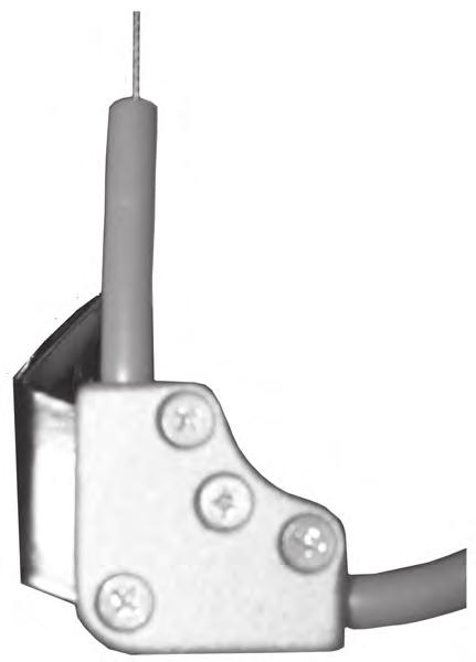
1 QUIC-OCK Mechanical Bracket Model QM-U Parts and Instruction Manual ZICO 045PM8 Rev The QUIC-OCK is a strapless CB bracket that utilizes a flip down, PVC-coated top clamp and an adjustable footplate to securely lock an CB cylinder by its ends. To secure the cylinder, place the CB valve into the footplate, lower the top clamp around the cylinder, and pull up on the red locking knob to lock into place. The QUIC-OCK is NFP compliant and third party tested to exceed the 9G standard. To release the CB, simply pull on the release cord. Fits most CBs with only minor adjustments. Easy to retrofit into new or old seats. Works with most center pull releases. Model QM-U-OPR Model QM-U WRNING: Bracket and CB harness are not to be used in place of a seat belt. The Quic-ock Mechanical WKWY Bracket will accommodate the optional pull release, model QM-U-OR. To order the Quic-ock with the optional pull release already attached, order QM-U-OPR. MODE DECRIPTION WT./@ IN B. QM-U Quic-ock Mechanical Bracket 4.0 QM-U-OPR Quic-ock Mechanical Bracket with Optional Pull Release 4. QM-U-OR Optional Pull Release for the Quic-ock 0.6
2 Parts Diagram - QUIC-OCK - Model QM-U Page
3 Parts Breakdown - QUIC-OCK - Model QM-U ITEM NO. PRT NO. DECRIPTION QTY Top Clamp Upper Bracket Backplate Footplate Cam Cyl. ocator/bumper djustment Rod, Footplate Footplate Guide Cable ssembly, Pull Release Bracket, Release ssy Counter pring, Top Clamp, H Counter pring, Top Clamp, RH pring, Breakaway pring, Cam Return leeve, Cam Pivot, /OD x 4 G. x.5 G Cam Handle pacer, Top Clamp Pivot djust crew, Breakaway pring Knob, Footplate djustment pacer, dj. Rod, /OD x 4 G. (.08) x.8g T pacer, /8 ched 80 lum., 675OD x.4id x.65g Nut Inserts, /4-0 ZPZ Rubber Bumper Backup Plate, Bumper Elbow, Hex ide Elbow, C'ink ide Plastic Tubing pacer/ocator, Bumper Pull Release Knob top leeve pacer, 7/6OD x G. (.09) T. DWG Cam Handle ink Plate Cam Release Push Rod etscrew, #8-x/6 Flat Point abel, Model # ITEM NO. PRT NO. DECRIPTION QTY Knob, Cam ock Red, / Footplate Mounting Block Cotter Pin, /6 x /, ZP Hairpin Cotter Footplate Mounting pacer Clevis Pin, /6ø x /" G crew, 0- x 5/8" G crew, 0- x " G crew, /4-0 x /4 HH crew, /4-0 x " RDHD Torx, Bumper Mount crew, /4-0 x /4" HH crew, 5/6-8 x " HH, GR crew, 5/6-8 x /4 HH crew, /4-0 x FH, Torx crew, 5/6-8 x / Drive crew, # x " G Footplate pacer leeve Jam Nut, 0-, /8 HT, ZP Jam Nut, /-0 Thin, ZP Nut, /4-0, elf ock Nut, 5/6-8, Hex, elf oc Nut, /8-6 Hex, Plain crew, 0- x /4 PH Phil Nut, 5/6-8, Hex, Plain Nut, 0- Hex, Nylon ock Plainwasher, #0 ZO M/ 7/6" O.D Plainwasher, /4ø Plainwasher, 5/6ø Washer, /4ø, GR8,./6 Thk Bar Washer, 5/6 NOM. x /4x /6 ZP Washer, /ID x 7/8OD x /6 Thk., ockwasher, /4ø plit Washer, Plastic, /ID x /4OD x ockwasher, 5/6øNOM., plit ockwasher, Intrnal Tooh, #0 ZP 4 Page
4 Parts Diagram & Breakdown - QUIC-OCK - Model QM-U-OR ITEM PRT NO. DECRIPTION QTY. B Release Cable ssembly B Yellow Tubing 0" B Barbed Fitting 4B Pull Release Bracket, Upper 5B Pull Release Bracket, Release End 6B Conduit with Crimped Fitting 7B crew, Hex Hd 8B Push Nut 9B Nut, Nylon ock 0B #6 x 5/6" Drive crew B Pull Release Knob B top leeve B #8- x /6" et crew 4B Release Bracket 5B /4-0 x /4" crew 6B /4" Plainwasher 8B Hairpin Cotter 9B #0 Plainwasher 0B /6" x /" Clevis Pin B x 5/8" crew Page 4
5 Parts Terminology - QUIC-OCK - Model QM-U Page 5


6 M CB Warning If using the Quic-ock with an M CB cylinder, you must read this important information: TO FEY ECURE YOUR M CB If your M CB cylinder uses a gauge guard with the approximate dimensions shown in Ref., you must use the included adapter plate as shown in Ref. B, secured to the inside of the Footplate as shown. If your M CB cylinder has a smaller gauge guard, this adapter should not be used. Damage may result when using the adapter with a smaller gauge guard. Ref. Ref. B If your M CB cylinder is a Model G, you must use the included Footplate Riser as shown in Ref. C, secured to the Footplate with double-sided tape (included). The adapter plate should not be used. Ref. C Page 6
.. Place the bottom of your CB ir Cylinder Valve in the Footplate ssembly.")
7 et-up Instructions - QUIC-OCK. oosen the T-0 torx head screw holding the Footplate Guide to the Footplate just enough so that the Footplate Guide can slide back and forth on the Footplate. If you are using an M cylinder, the M footplate extension may need to be installed (see page 6).. Place the bottom of your CB ir Cylinder Valve in the Footplate ssembly. While keeping the ir Cylinder Valve as far forward as it will go in the Footplate "pocket", slide the Footplate Guide so there is approximately /8" clearance between the Footplate Guide and the bottom of the ir Cylinder Valve (see Figure, below). Figure. Remove the CB ir cylinder from the Footplate and re-tighten the T-0 torx head screw holding the Footplate Guide. 4. Determine the most accommodating position for your Upper Bracket ssembly using the information from the chart on pages -5 and the diagram on page 6. If your QUIC-OCK was not pre-set for your specific CB prior to shipping, it will come standard in the "B" position. If your CB is currently in the correct position, skip to step 9. Page 7
 and set the")
 # Phillips head screws holding the Bumper pacer ocator (see Figure,")
8 5. If you need to adjust the Upper Bracket ssembly to a different position, remove the T-0 torx head screw holding the Cylinder ocator Bumper (see Figure, below) and set the Cylinder ocator Bumper aside. Remove the () # Phillips head screws holding the Bumper pacer ocator (see Figure, below), and set the Bumper pacer ocator aside. Figure Figure Page 8
 T-7 torx head screws. 8. If using this bracket with a 0 min. 5500 PI air cylinder, refer to page 0 now.")
9 6. Remove the (4) T-7 torx head screws that are holding the Upper Bracket ssembly in place. Be sure not to let the weight of the Upper Bracket hang on the djustment Rod before reattaching. 7. Reattach the Upper Bracket ssembly in the desired position using the (4) T-7 torx head screws. 8. If using this bracket with a 0 min PI air cylinder, refer to page 0 now. Otherwise, reattach the Bumper pacer ocator to the Upper Bracket ssembly with the () # Phillips head screws. 9. Referring again to the CB Reference chart on pages -5 and the diagram on page 6, determine the optimal bumper location for the Cylinder ocator Bumper (Note: If using this bracket with a flat-top air cylinder, the standard Cylinder ocator Bumper must be replaced with a modified version, see page 0). Reattach the Cylinder ocator Bumper by inserting the T-0 torx head screw into the appropriate bumper location hole in the Bumper pacer ocator, leaving the T-0 torx head screw loose enough to allow the Cylinder ocator Bumper to slide up and down. Temporarily slide the Cylinder ocator Bumper as far up as it will go. 0. Measure the overall length of your desired air cylinder from bottom of the air cylinder valve to top of the air cylinder (see Figure 4, below). dd /" to this measurement. Figure 4. Measure the distance from the inside bottom of the Footplate to the inside top of the closed Top Clamp (see Figure 5, page 0). This distance should equal your overall length of the air cylinder plus /". Use the djustment Rod Knob to turn the Footplate djustment Rod and achieve this measurement. Page 9

.")
10 Figure 5. Open the Top Clamp. Place the air cylinder valve in the Footplate and move the CB into the bracket, closing the Top Clamp as the top of the air cylinder passes the front of the Top Clamp (see Figure 6, below). Pull the ock ever Knob up firmly to lock the CB in place. Figure 6 Page 0
.")
11 . The Top Clamp should be engaging the CB without wedging between the air cylinder and the CB harness frame (see Figure 7, below). Figure 7 Page
12 4. With the CB in the stowed position, slide the Cylinder ocator Bumper up or down until it touches the air cylinder and keeps it held toward the front of the Top Clamp. eave a slight amount of clearance (up to /6") between the top of the air cylinder and the Cylinder ocator Bumper. When positioned correctly, remove the air cylinder and tighten the T-0 torx head screw on the Cylinder ocator Bumper. 5. If the air cylinder cannot be held against the front of the Top Clamp by the Cylinder ocator Bumper, it may be necessary to change the location of the T-0 torx head screw holding the Cylinder ocator Bumper to a different bumper location (,, or 4) in order to get the correct fit described in step The CB should be held firmly in place. If it is not, repeat steps 9-5 and fine-tune until a satisfactory final adjustment is achieved. 7. Check that locking and unlocking functions are working properly. Page
13 CB Reference Chart CB Brand, Model ircyl Type Upper Bracket ocation Bumper ocation Bumper Position Draeger ir Boss Evolution Plus P 00 Draeger ir Boss Evolution Plus P 00 Draeger ir Boss Evolution Plus P 00 Draeger ir Boss Evolution Plus P 00 Draeger ir Boss Evolution Plus P 00 0 Min 6 PI 0 Min 6 PI lum Flat Top* 0 Min 4500 PI 45 Min 4500 PI 60 Min 4500 PI Draeger ir Boss Evolution Draeger ir Boss Evolution Draeger ir Boss Evolution Draeger ir Boss Evolution Draeger ir Boss Evolution 0 Min 6 PI 0 Min 6 PI lum Flat Top* 0 Min 4500 PI 45 Min 4500 PI 60 Min 4500 PI Draeger P 7000 Draeger P 7000 Draeger P 7000 Draeger P 7000 Draeger P Min 6 PI 0 Min 6 PI lum Flat Top* 0 Min 4500 PI 45 Min 4500 PI 60 Min 4500 PI Global afety Pioneer Global afety Pioneer Global afety Pioneer 0 Min 4500 PI 45 Min 4500 PI 60 Min 4500 PI Interspiro piromatic 4 Interspiro piromatic 4 Interspiro piromatic 4 0 Min 4500 PI 45 Min 4500 PI 60 Min 4500 PI II Viking DX II Viking DX II Viking DX 0 Min 4500 PI 45 Min 4500 PI 60 Min 4500 PI B von-ii Viking Z-7 von-ii Viking Z-7 von-ii Viking Z-7 von-ii Viking Z-7 0 Min 6 PI 0 Min 4500 PI 45 Min 4500 PI 60 Min 4500 PI B B M Firehawk M Firehawk M Firehawk M Firehawk M Firehawk M Firehawk M Firehawk 0 Min 6 PI 0 Min 6 PI lum Flat Top* 0 Min 000 PI 0 Min 4500 PI 45 Min 4500 PI 45 Min 4500 PI ow Profile 60 Min 4500 PI * Flat top cylinders require an additional Modified ocator Bumper, Model (see page 0). Page
14 CB Reference Chart CB Brand, Model ircyl Type Upper Bracket ocation Bumper ocation Bumper Position M Firehawk M-7 M Firehawk M-7 M Firehawk M-7 M Firehawk M-7 M Firehawk M-7 M Firehawk M-7 M Firehawk M-7 0 Min 6 PI 0 Min 6 PI lum Flat Top* 0 Min 000 PI 0 Min 4500 PI 45 Min 4500 PI 45 Min 4500 PI ow Profile 60 Min 4500 PI M tealth M tealth M tealth M tealth M tealth M tealth 0 Min 6 PI 0 Min 6 PI lum Flat Top* 0 Min 000 PI 0 Min 4500 PI 45 Min 4500 PI 60 Min 4500 PI cott P-50 cott P-50 cott P-50 cott P-50 cott P-50 cott P-50 cott P-50 cott P-50 cott P-50 0 Min 6 PI 0 Min 6 PI lum Flat Top* 0 Min 4500 PI 45 Min 4500 PI ow Profile 45 Min 4500 PI 45 Min 5500 PI w/o Prot Cover 45 Min 5500 PI w/prot Cover 60 Min 4500 PI 75 Min 5500 PI cott P-75 cott P-75 cott P-75 cott P-75 cott P-75 cott P-75 cott P-75 cott P-75 cott P-75 cott P-75 0 Min 6 PI 0 Min 6 PI lum Flat Top* 0 Min 4500 PI 0 Min 5500 PI 45 Min 4500 PI 45 Min 4500 PI ow Profile 45 Min 5500 PI w/o Prot. Cover 45 Min 5500 PI w/prot. Cover 60 Min 4500 PI 75 Min 5500 PI * Flat top cylinders require an additional Modified ocator Bumper, Model (see page 0). 0 Min 5500 PI air cylinders require an additional Bumper pacer Kit, Model (see page 0). Page 4
15 CB Reference Chart CB Brand, Model ircyl Type Upper Bracket ocation Bumper ocation Bumper Position cott NXG cott NXG cott NXG cott NXG cott NXG cott NXG cott NXG cott NXG cott NXG 0 Min 6 PI 0 Min 6 PI lum Flat Top* 0 Min 4500 PI 45 Min 4500 PI 45 Min 4500 PI ow Profile 45 Min 5500 PI w/o Prot. Cover 45 Min 5500 PI w/prot. Cover 60 Min 4500 PI 75 Min 5500 PI cott NXG7 cott NXG7 cott NXG7 cott NXG7 cott NXG7 cott NXG7 cott NXG7 cott NXG7 cott NXG7 cott NXG7 0 Min 6 PI 0 Min 6 PI lum Flat Top* 0 Min 4500 PI 0 Min 5500 PI 45 Min 4500 PI ow Profile 45 Min 4500 PI 45 Min 5500 PI w/o Prot. Cover 45 Min 5500 PI w/prot. Cover 60 Min 4500 PI 75 Min 5500 PI urvivair Panther urvivair Panther urvivair Panther urvivair Panther urvivair Panther 0 Min 6 PI 0 Min 4500 PI 45 Min 4500 PI ow Profile 45 Min 4500 PI 60 Min 4500 PI B urvivair Warrior urvivair Warrior urvivair Warrior urvivair Warrior urvivair Warrior 0 Min 6 PI 0 Min 4500 PI 45 Min 4500 PI ow Profile 45 Min 4500 PI 60 Min 4500 PI * Flat top cylinders require an additional Modified ocator Bumper, Model (see page 0). 0 Min 5500 PI air cylinders require an additional Bumper pacer Kit, Model (see page 0). Page 5
16 Page 6

17 If in position If in position B Page 7
18 Mounting Requirements - QUIC-OCK Minimum of () mounting points at least 0" apart using 5/6" O.D. screws. pacer required between Quic-ock Backplate and mounting surface (provided). Mounting surface must be able to withstand a pull-out force of 450 lbs. Page 8
, drill two () holes in the seat frame. Thicker seat frames may require a larger bit size, #8 (.69).")
19 Mounting Instructions - Optional Pull Release. Position the Pull Release Bracket, complete with yellow tube and release cable, in the desired location against the eat Frame.. Using a #9 drill bit (.66), drill two () holes in the seat frame. Thicker seat frames may require a larger bit size, #8 (.69).. ttach the Pull Release Bracket to the seat frame using two () 0- x /8" thread forming screws (supplied). Be sure to carefully run the cable and conduit around the seat and bracket without causing kinks in the cable or interference with the bracket's functions. Example of Possible Mounting ocations Page 9

.")

20 ocator Bumper pacer Kit, Model For use with 0 min PI air cylinders. tacks between standard ocator Bumper pacer and backplate to better accommodate the 5.5 cylinder's thinner shape and achieve maximum locking efficiency. Note: 45 min. and larger 5.5 cylinders do not require this kit. pacer Installation Instructions:. tack the original spacer on top of your new kit spacer (see left).. et these spacers, together, against the Upper Bracket assembly of your CB, positioned for your 5.5 cylinder. ecure using the longer Phillips head screws included with this kit.. Continue with tep 9 of CB bracket adjustments. Modified ocator Bumper for Flat-Top Cylinders, Model For use with flat-top cylinders. Replaces tandard ocator Bumper component to better accommodate the flat-top cylinder shape and achieve maximum locking efficiency. Page 0


 49-68 FX: (5)")
21 Operating Instructions - QUIC-OCK - Model QM-U These instructions should only be used after the QM-U has been adjusted for the CB that is being used.. Place the valve of the CB in the Footplate. If the valve does not sit properly in the Footplate, the bracket will not lock safely.. Place the air cylinder against the Cylinder ocator Bumper and pull down the top clamp.. While applying downward pressure to the Top Clamp, pull up on the red ock ever Knob. When the knob is completely up, the CB is secured. Ziamatic Corp. TO FREE: West College venue, P.O. Box 7, Yardley, P (5) FX: (5) *ZICO is a registered trademark for fire, safety and marine products made by Ziamatic Corp. Copyright Ziamatic Corp. -6 Page
MODEL DESCRIPTION IN LBS.
 QUIC-RELEASE Oxygen Tank System Model QR-OTS- -U Parts and Mounting Information ZICO 00PM0 Rev. --7 Model QR-OTS-U allows you to mount any "M" through "J" cylinder. The system uses a QR-MV Multiversal
ZICO. Center Pull Release in Bostrom 450 Tanker Seat 1026PM5 REV
 Center Pull Release in Bostrom 450 Tanker Seat Manual For the EZ-LOC Mechanical Bracket ZICO 1026PM5 REV. 2-24-12 The center pull release kit allows the SCBA bracket to be released by pulling a "T" handle
ZICO* 3096PM1 QUIC-LADDER SWING OUT & DOWN VEHICLE LADDER. Stores ladder parallel to the body.
 QUIC-LADDER SWING OUT & DOWN VEHICLE LADDER ZICO* 309PM REV. --0 Stores ladder parallel to the body. Release the locking handle and pull the ladder out to a comfortable climbing angle. The ladder automatically
ZICO 3094PM1. Model VS REV Retracted. Extended
 QUIC-STEP Retractable Vehicle Step Model VS-- Parts and Instruction Manual ZICO 309PM REV. -- Retracted Extended Designed specifically for use on fire and emergency vehicles. May be retrofitted onto existing
SAE 5W20, or other clean hydraulic fluid with a viscosity of 150 to 300 SUS at 100 degrees Fahrenheit. System capacity (dry) is 50 ounces.
 is 50 ounces.") QUIC-LIFT Horizontal Ladder & Portable Tank Systems Model HLAS-500-KIT Hydraulic Power Unit (Pump & Motor) and Hydraulic Cylinder Upgrade Kit ZICO 3097PM22 REV. 11-9-16 Note: This manual should be used
QUIC-LIFT Horizontal Ladder & Portable Tank Systems Model HLAS-500-KIT Hydraulic Power Unit (Pump & Motor) and Hydraulic Cylinder Upgrade Kit ZICO 3097PM22 REV. 11-9-16 Note: This manual should be used
MODEL DESCRIPTION IN LBS.
 QUIC-STEP Retractable Vehicle Step Model VS--9 Parts and Instruction Manual ZICO 309PMii Rev. -- Designed specifically for use on fire and emergency vehicles. May be retrofitted onto existing apparatus.
DESCRIPTION. 10" Square Valve 10" Valve for United Plastics Tank Valve Handle-Complete Assembly Auxilliary Handle Lock less Hardware (see page 12)
") QUIC-FLOW MANUAL DUMP VALVE ZICO 070PM REV 3-5- QUIC-FLOW valves are the fastest dumping systems for tankers, bar none, dumping up to 800 GPM. Mounting the valve at the bottom of the tank provides approximately
QUIC-FLOW MANUAL DUMP VALVE ZICO 070PM REV 3-5- QUIC-FLOW valves are the fastest dumping systems for tankers, bar none, dumping up to 800 GPM. Mounting the valve at the bottom of the tank provides approximately
ZICO 2070PM1 REV Page 1
 QUIC-FLOW Dump Valves Parts and Instruction Manual ZICO 070PM REV. 9-0- Zico dump valves are uniquely designed to stop annoying leakage. A special slotted hinge over the door shifts when in the closed
3094PM1ii (Model VS-24-11) & 3094PM4ii (Model VS-24-9)
 & 3094PM4ii (Model VS-24-9)") QUIC-STEP Retractable Vehicle Step Model VS-24-11 and VS-24-9 InPOWER Control Module Upgrade Manual ZICO 3094PM9 REV. 1-13-17 Note: This manual provides instruction when upgrading a vehicle step from a
QUIC-STEP Retractable Vehicle Step Model VS-24-11 and VS-24-9 InPOWER Control Module Upgrade Manual ZICO 3094PM9 REV. 1-13-17 Note: This manual provides instruction when upgrading a vehicle step from a
ZICO 3092PM1 REV Booklet contains the following sections:
 QUIC-LIFT Outside Arm Ladder System Model OALS Parts and Instruction Manual ZICO 309PM1 REV. 7-1-13 Booklet contains the following sections: I. Systems Available II. Operating the System III. Standard
WARNING NOTICE CAUTION ASSEMBLY INSTRUCTIONS
 MODEL 284 EZ-GLIDE SYSTEM 10' HIGH CUBE VAN DRIVER SIDE ALUMINUM DROP DOWN LADDER RACK ATTENTION Read and understand all instructions and warnings before operating or using this product. WARNING This product
RC-200EX / RC-150EX Rim Clamp Tire Changer
 RC-200EX / RC-150EX Rim Clamp Tire Changer For servicing motorcycle and ATV tire/wheel assemblies as well as automotive and most light truck tire/wheel assemblies (holds 6 to 8-inch wheels for manual tire
GENUINE PARTS INSTALLATION INSTRUCTIONS
 GENUINE PARTS INSTALLATION INSTRUCTIONS 1. DESCRIPTION: Trailer Tow mirror kit (with power and heated) Trailer Tow mirror kit (with power, heated, and memory) 2. APPLICATION: 04 Titan, Armada, QX56 LE,
Automatic Lawn Tractor Model Series 600
 Illustrated Parts Manual utomatic Lawn Tractor Model Series 00 MTD LLC, P.O. BOX 11 CLEVELND, OHIO -00 Printed In US Form No. -08 (February 18, 008) Fender, Deck Lift & Seat 5 5 Models w/ Manually djusting
5035 A/E. Rim Clamp Tire Changer. Parts Identification
 5035 A/E Rim Clamp Tire Changer Parts Identification READ these instructions before placing unit in service KEEP these and other materials delivered with the unit in a binder near the machine for ease
Model Series E6A5E, E645E & E665E
 Model Series EAE, EE & EE 0. -0 Housing R.H. -0 Housing L.H.. 0-0 Hex Screw /- x.. -0A Spiral Axle -00A Spiral Axle. -0 Key. -0 Pin-Spiral. -0 Shaft-Worm. -0 Gear-Worm. -0 Collar-Thrust. -0 Plug 0. -0
Castle Model TSM-21 Standard Screw Pocket Machine
 Castle Model TSM-21 Standard Screw Pocket Machine "For Models with Serial Number 62481 and Above" Items Included with Machine Part No. Description Qty B00964 Castle 9/64 Cobalt Drill Bit w 1/4" Shank 1
3010 Series. 4 Latch. Hold Open Arm Door Closers Regular Arm. Installation Sequence. Mark and Drill Holes. Parts. Sweep. Set Hold Open.
 000 eries Tri-Packed Non Handed Closer Instructions eft Hand - H ight Hand everse - H eft Hand - H ight Hand everse - H egular rm ee Page ee Page 5 eft Hand - H ight Hand everse - H Parallel rm ee Pages
ZICO 3097PM6 I. SYSTEMS AVAILABLE INSTALLING THE ACCESS SYSTEM. A. Preparation for Mounting B. Electrical System C. Mounting Suggestions
 QUIC-LIFT Horizontal Ladder & Portable Tank Systems Model HLAS/Model HPTS ZICO 3097PM6 Parts and Instruction Manual REV. 8-6-5 I. SYSTEMS AVAILABLE II. INSTALLING THE ACCESS SYSTEM A. Preparation for Mounting
SECTION 12: ILLUSTRATED PARTS LIST
 SECTION : ILLUSTRTED S LIST (for choke) (for throttle) 0 0-0 Screw, #- x.0 0-0 Screw, /- x.0 0-0 Screw, /- x.0 0- Screw, #0- x. 0- Socket Cap Screw, /- x. 0- Self-tapping Screw, /- x. -00 Flange Lock Nut,
PLOW MOUNT GLACIER PRO KIT
 PLOW MOUNT GLACIER PRO KIT P/N 2880262 APPLICATION FOR USE WITH THE GLACIER PRO MID-SIZE PLOW SYSTEM (P/N 2880260) ON 2015 AND NEWER RZR 00 MODELS BEFORE YOU BEGIN Read these instructions thoroughly and
Easy Cover. Installation Instructions. Attention Dealers: Please give this owners manual to the customer when the product is delivered.
 Serving the Truck & Trailer Industry Since 1944 Model 9 10 Spring Flange Mount Easy Cover Attention Dealers: Please give this owners manual to the customer when the product is delivered. Call 800-3-94
Castle Model TSM-35. Heavy Duty Screw Pocket Machine. For Models with Serial Number and Above Items Included with Machine
 Castle Model TSM-35 Heavy Duty Screw Pocket Machine For Models with Serial Number 63658 and Above Items Included with Machine Part No. Description Qty B02964 9/64" Castle Premium Brad Point Drill Bit w/
Installation Guide. Stowe Cargo Management System. Table of Contents
 Installation Guide Stowe Cargo Management System Table of Contents 1. Pre-Installation (Page 2) a. Notes, Installation Kit contents & Tools needed 2. How to Install the Stowe Cargo Management System (Pages
POLY TIP-DOWN WINDSHIELD KIT
 POLY TIP-DOWN WINDSHIELD KIT P/N 2883261 APPLICATION Verify accessory fitment at Polaris.com. BEFORE YOU BEGIN Read these instructions and check to be sure all parts and tools are accounted for. Please
Parts Manual. Models Mfg. No. Description Brute, 14.5TP 29" Dual Stage Snowthrower (2012)
") Parts Manual Models Mfg. No. Description 1696282-00 Brute, 14.5TP 29" Dual Stage Snowthrower (2012) Manual Part No. 1756728 Revision C Rev. Date: 8/21/2013 Table Of Contents PRODUCT COMPONENTS PAGES Handles
Parts Manual Models Mfg. No. Description 1696282-00 Brute, 14.5TP 29" Dual Stage Snowthrower (2012) Manual Part No. 1756728 Revision C Rev. Date: 8/21/2013 Table Of Contents PRODUCT COMPONENTS PAGES Handles
Siderolling Tarp Systems Under 9 6 Wide
 Load Loc Select Maximizer Grain Carts Grain Bagger Siderolling Tarp Systems Under 9 6 Wide CRANK STYLE INSTALLATION INSTRUCTIONS MICHEL S INDUSTRIES, LTD. P.O. BOX 119 ST. GREGOR, SK. S0K 3X0 PH:306.366.2184
GEM Car Parts Direct
 ASSY, DRIVE LINE - 72 VOLT 46 IN WIDE - 1 0113-01093 ASSY, HALF SHAFT - LH 1 2 0113-01094 ASSY, HALF SHAFT - RH (LONG) 1 3 0313-00168 BUMPER, RESILIENT - DIFF TO MOTOR - - 1 4 0313-00417 KEEPER, GEARBOX
Installation Instructions
 Outdoor plit Flow Center Kit FCP11BDO (1 pump) FCP21BDO (2 pumps) For plit Geothermal Heat Pump models GZ & H Installation Instructions NOTE: Read the entire instruction manual before starting the installation.
Installation Instructions
 eft Hand Door H ight Hand everse H ight Hand Door H eft Hand everse H ight Hand Door H eft Hand everse H egular rm ee Page Top Jamb ee Page 5 Parallel rm ee Pages & Instructions CUTION n Incorrectly installed
INSTRUCTION, GPTLR POWER DOWN HAND PUMP KIT
 LIFT CORPORATION Sht. 1 of 29 DSG# M-09-18 Rev. ~ Date: 03/05/14 INSTRUCTION, GPTLR POWER DOWN HAND PUMP KIT GPTLR KIT P/N 283332-01 HAND PUMP MOUNT BRACKET P/N 282381-01 QTY. 1 HAND PUMP HANDLE MOUNT
Reproduction. Not for REAR ENGINE RIDER HYDRO DRIVE 33" 15.5 TP RE SERIES. Parts Manual for RE210
 Parts Manual for REAR ENGINE RIDER HYDRO DRIVE 33" 15.5 TP RE SERIES Model No. Description 7800952-00 RE210 Briggs & Stratton Yard Power Products Group 535 Macon Road McDonough, GA, 30253 U.S.A. 800-935-2967
Hiniker Company th St. P.O. Box 3407 Mankato, MN 56002
 VEHICLE INSTALLATION INSTRUCTIONS FOR: FORD 4x4: 008-06 SUPER DUTY F50-350 - 450-550 Page of 5 Hiniker Company 58766 40th St. P.O. Box 3407 Mankato, MN 5600 INSTRUCTION SHEET NO: 50370 Rev. B September
INSTALLATION AND PARTS MANUAL MODEL 30B FOR NEW HOLLAND DC75, DC85, DC95X
 CARCO INSTALLATION AND PARTS MANUAL MODEL 30B FOR NEW HOLLAND DC75, DC85, DC95X NOTE: This manual covers mounting and control group installation, and parts specific to this winch on the specified tractor.
Illustrated Parts Manual
 Illustrated Parts Manual 00 Series Snow Thrower Two Stage MTD LLC, P.O. BOX 331 CLEVELAND, OHIO 13-001 Printed In USA Form No. -033 (August 2, 200) Auger & Auger Housing 5 1 1 13 3 25 23 1 15 53 1 2 22
Reproduction. Not for. Large Frame Dual Stage Snowthrowers. Parts Manual
 Parts Manual Attachment Mfg. No. Description 1695996-01 (SIH1428SE), 14.5TP 28" Dual Stage Snowthrower (CE/Export) Large Frame Dual Stage Snowthrowers 1695997-01 (SIH1730SE), 16.5TP 30" Dual Stage Snowthrower
ThermoLazer Pavement Marking System A
 ThermoLazer Pavement Marking System 313880A - For professional application of thermoplastic traffic marking compound materials (reflective beads applied simultaneously with screeding) - - For outdoor use
PROSPECTOR TRACK MOUNT KIT
 PROSPECTOR TRACK MOUNT KIT P/N 2882109 APPLICATION Verify accessory fitment at Polaris.com. BEFORE YOU BEGIN Read these instructions and check to be sure all parts and tools are accounted for. Please retain
SPEEDWING Snowplow. Model 8600SW Blade Crate Assembly Big Box Assembly Parts List
 May 1, 01 Lit. No. 0686, Rev. 11 SPEEDWING Snowplow Model 8600SW Blade Crate Assembly 5750-1 Big Box Assembly 5755 Parts List This Parts List is for BLIZZARD SPEEDWING snowplows with serial numbers beginning
SPEEDWING Snowplow. Model 8600SW Blade Crate Assembly Big Box Assembly Parts List
 November 15, 013 Lit. No. 305, Rev. 0 SPEEDWING Snowplow Model 8600SW Blade Crate Assembly 5751 Big Box Assembly 5756 Parts List This Parts List is for BLIZZARD SPEEDWING snowplows with serial numbers
RC-100. Parts Identification
 RC-100 Rim Clamp Tire Changer For servicing motorcycle and ATV tire/wheel assemblies, also single piece automotive and most light truck tire/wheel assemblies s Identification READ these instructions before
INTEGRATED1500LB WINCH KIT
 INTEGRATED1500LB WINCH KIT P/N 2882798 APPLICATION Verify accessory fitment at Polaris.com. BEFORE YOU BEGIN Read these instructions and check to be sure all parts and tools are accounted for. Please retain
PARTS LIST. Reproduction. Not for. Mower Decks. Mfg. No. Description EZM2042, 20HP B&S w/42" Mower Deck (2009)
") PARTS LIST Mower Decks Mfg. No. Description 7800490 EZM2042, 20HP B&S w/42" Mower Deck (2009) Manual Part No. Revision A Rev. Date: 11/5/2009 Table Of Contents PRODUCT COMPONENTS PAGES Frame, Body & Seat
PARTS LIST Mower Decks Mfg. No. Description 7800490 EZM2042, 20HP B&S w/42" Mower Deck (2009) Manual Part No. Revision A Rev. Date: 11/5/2009 Table Of Contents PRODUCT COMPONENTS PAGES Frame, Body & Seat
Reproduction. Not for HYDRO DRIVE 46" 22 HP ZTR 360Z SERIES. Parts Manual for ZT2246
 Parts Manual for HYDRO DRIVE 46" 22 HP ZTR 360Z SERIES Model No. Description 2691316-00 ZT2246 Briggs & Stratton Yard Power Products Group 3515 N. 124 Street / PO Box 702 Wauwatosa, WI 53222 U.S.A. 800-935-2967
Z-Gate Universal Shifter
 Installation Instructions Z-Gate Universal Shifter Fits: GM, Ford, Lincoln and Chrysler Transmissions See Application Guide for Specific Applications Part #80681 Rev 06/01/2018 WORK SAFELY! For maximum
MidCap Rotary Rake. Illustrated Parts Breakdown
 MidCap Rotary Rake Illustrated Parts Breakdown Page Page Page Page Page Page Page Page Page Page 0 Page Page Page Page Page Page Page Page Page Main Frame Transport Wheel Assembly Lift Arm Assembly Main
Reproduction. Not for HYDRO DRIVE 46" 22 HP ZTR 360Z SERIES. Parts Manual for ZT2246
 Parts Manual for HYDRO DRIVE 46" 22 HP ZTR 360Z SERIES Model No. Description 2691316-00 ZT2246 Briggs & Stratton Yard Power Products Group 3515 N. 124 Street / PO Box 702 Wauwatosa, WI 53222 U.S.A. 800-935-2967
Procharger Stage II Intercooled Supercharger System (11-14 GT)
") Procharger Stage II Intercooled Supercharger System (11-14 GT) Installation Time: Approximately one day. Installed on 2012 Mustang GT 5.0/Manual Required Tools 3/8 Socket Set (Standard and Metric) 1/2
Procharger Stage II Intercooled Supercharger System (11-14 GT) Installation Time: Approximately one day. Installed on 2012 Mustang GT 5.0/Manual Required Tools 3/8 Socket Set (Standard and Metric) 1/2
Please read BOTH these Installation Instructions and the General Towing Instructions before attempting to install or operate this equipment.
 Serial Number Please read BOTH these and the General Towing Instructions before attempting to install or operate this equipment. 1. Blue Ox towing products and accessories are intended to be installed
Assembly Instructions
 Assembly Instructions Part Number Description Model Approx. Assembly Time 99994-0903 Windshield Wiper Kit Mule SX 1 Hour WARNING Improper installation of this accessory could result in an accident causing
K-SERIES PUBLIC USE SPARE PARTS
 -PRINT- AUGUST 2013 IV. T K-SERIES PUBLIC USE SPARE PARTS - TABLE OF CONTENTS- SPARE PARTS his chapter contains parts diagrams and lists for the RICON K-Series Public Use wheelchair lift. The exploded
»Product» Safety Warning
 J1455, J1456 Installation Instructions 1984-2001 Jeep Cherokee XJ 4.5 Suspension Lift Read and understand all instructions and warnings prior to installation of product and operation of vehicle. Zone Offroad
Parts Catalog. S-Series Slicer Automatic. Model:
 , 07 99509 ECN 077 Parts Catalog S-Series Slicer Automatic Model: SGA SGA 05/08/07 Rev. J IMPORTANT! TO EXPEDITE SHIPMENT OF PARTS, ALWAYS SPECIFY MODEL, REV, PART NUMBER, AND SERIAL NUMBER OF UNIT. GLOBE
Models 820 and 840 2
 Models 820 and 840 2 Models 820 and 840 1 783-0250 Hood 2 738-0952 Shld. Bolt.375" Dia. x.5" 3 736-0175 Spr. Washer.265" I.D. x.562" OD 4 710-0751 Hex Bolt 1/4-20 x.62" * 6 7-0271 Hex Sems Nut 1/4-20 Thd.
PORTA-DOCK, INC. 65A 1155 DOUBLE PERSONAL WATERCRAFT LIFT
 Page 1 of 9 PORTA-DOCK, INC. 65A 1155 DOUBLE PERSONAL WATERCRAFT LIFT Thank you for purchasing our product! Please read these instructions and follow them step by step.* STEP 1. Separate and group like
A DIVISION OF DOUGLAS DYNAMICS, L.L.C.
 April, 00 Lit. No. 0686, Rev. 05 SPEEDWING Snowplow 8600SW Snowplow Parts List A DIVISION OF DOUGLAS DYNAMICS, L.L.C. Lit. No. 0686, Rev. 05 April, 00 BLADE COMPONENTS... OFF-TRUCK COMPONENTS...5 Pivot
Boom Mounting Kit Multi-Pro
 Form Number 3356-121 Rev A Boom Mounting Kit Multi-Pro 1200, 1250 and 5700-D Model No. 41323-260000001 and up. Parts Catalog Ordering Replacement Parts To order replacement parts, please supply the part
Hiniker Company th St. P.O. BOX 3407 Mankato, MN VEHICLE INSTALLATION INSTRUCTIONS FORD 4x4: SUPER DUTY F
 Page of VEHICLE INSTALLATION INSTRUCTIONS FORD x: 00-007 SUPER DUTY F0 30 0 0 INSTRUCTION SHEET NO: 037 Rev. A IMPORTANT: Read The Snowplow Operators Manual Before Assembling This Kit. MFR. Snowplow Prep
! CAUTION! ! WARNING!
 Assembly Instructions! 3N-3010P, No-Till Flat Fold Marker Option Used with: 3N-3010P Drills When you see this symbol, the subsequent instructions and warnings are serious - follow without exception. Your
7/18 HJ26077 Rev 16. US Pat. 7,506,886 US Pat. 7,753,392 CA Pat. 2,576,427 AS Pat PAGE 1
 7/18 HJ26077 Rev 16 US Pat. 7,506,886 US Pat. 7,753,392 CA Pat. 2,576,427 AS Pat. 2007200421 PAGE 1 WARRANTY POLICY, OPERATOR MANUALS & REGISTRATION Go online to www.demco-products.com to review Demco
Installation Instructions. Non Hold Open Models. Sized (Sizes 2,3,4,5) Weaker BC 9303BC 9304BC 9305BC. Stronger +
 Weaker BC 9303BC 9304BC 9305BC. Stronger +") O Right Hand RH eft Hand Reverse HR eft Hand H Right Hand Reverse RHR eft Hand H Right Hand Reverse RHR Regular rm ee Page Top Jamb ee Page Parallel rm ee Pages 3 & UTION Instructions Non Hold Open Models
O Right Hand RH eft Hand Reverse HR eft Hand H Right Hand Reverse RHR eft Hand H Right Hand Reverse RHR Regular rm ee Page Top Jamb ee Page Parallel rm ee Pages 3 & UTION Instructions Non Hold Open Models
Parts Catalog. S-Series Slicer Standard Automatic Frozen Option S13A. Model:
 , 07 995 ECN 077 Parts Catalog SA S-Series Slicer Standard Automatic Frozen Option Model: SA 05/08/07 Rev. H IMPORTANT! TO EXPEDITE SHIPMENT OF PARTS, ALWAYS SPECIFY MODEL, REV, PART NUMBER, AND SERIAL
General Information. Related Documents. Notations and Conventions B L R F R B F L. 3PYP Steering Kit 3PYP & 3PYPA Planters. Kit Description.
 Part Lists Great Plains Manufacturing, Inc. 1 3PYP Steering Kit 3PYP & 3PYPA Planters When you see this symbol, the subsequent instructions and warnings are serious - follow without exception. Your life
Ref Qty Part Description Part Number -1- Kit ( ) Contents:
 Contents:") REAR CANVAS DOOR KIT 900 XP RANGER CREW P/N 2879899 Application RANGER 900 XP CREW Before you begin, read these instructions twice and check to be sure all parts and tools are accounted for. Please retain
REAR CANVAS DOOR KIT 900 XP RANGER CREW P/N 2879899 Application RANGER 900 XP CREW Before you begin, read these instructions twice and check to be sure all parts and tools are accounted for. Please retain
INSTRUCTIONS, NISSAN TITAN TRUCK INSTALLATION KIT (C2 PICKUP LIFTGATES)
") LIFT CORPORATION Sht. 1 of 18 DSG# M-14-33 Rev. A Date: 05/31/2017 INSTRUCTIONS, NISSAN TITAN TRUCK INSTALLATION KIT (C2 PICKUP LIFTGATES) NISSAN TITAN PICKUP TRUCKS, 2004-2015 KIT P/N 295040-01 MOUNTING
LIFT CORPORATION Sht. 1 of 18 DSG# M-14-33 Rev. A Date: 05/31/2017 INSTRUCTIONS, NISSAN TITAN TRUCK INSTALLATION KIT (C2 PICKUP LIFTGATES) NISSAN TITAN PICKUP TRUCKS, 2004-2015 KIT P/N 295040-01 MOUNTING
Part # Mustang Tru-Turn Suspension Package
 350 S. St. Charles St. Jasper, In. 47546 Ph. 812.482.2932 Fax 812.634.6632 www.ridetech.com Part # 12099599 64-66 Mustang Tru-Turn Suspension Package Front Components: 1 12093699 Upper Strong Arms 1 12092899
MODEL NO & UP MODEL NO & UP MODEL NO & UP MODEL NO & UP
 MODEL NO. -900 & UP MODEL NO. 00-900 & UP MODEL NO. 0-900 & UP MODEL NO. 0-900 & UP SKID SPRAYER FORM NO. 99-055 REV. B SET-UP AND PARTS LIST Refer to the illustrated Parts List for the details of parts
Standard Duty Oil Filter Relocation Kit (OC-3)
") 3430 Sacramento Dr., Unit D San Luis Obispo, CA 93401 Telephone: 805/544-8748 Fax: 805/544-8645 www.maximummotorsports.com Standard Duty Oil Filter Relocation Kit (OC-3) Read all of the instructions before
3430 Sacramento Dr., Unit D San Luis Obispo, CA 93401 Telephone: 805/544-8748 Fax: 805/544-8645 www.maximummotorsports.com Standard Duty Oil Filter Relocation Kit (OC-3) Read all of the instructions before
BX88175 Installation Instructions ToadStop II Vacuum Brake System
 BX88175 Installation Instructions ToadStop II Vacuum Brake System Serial No. Customer supplied tools & supplies Utility knife, 12VDC tester, drill & bits: (1/8", 1/4", 5/8 ), ¼ socket drive bit, punch,
INSTALLATION, MAINTENANCE, & SAFETY INSTRUCTIONS
 Tarpaulin Systems Flip -N- Go / Quick Mount Flip -N- Go System INSTALLATION, MAINTENANCE, & SAFETY INSTRUCTIONS (800) CRAMARO (800) 272-6276 Plants In: Delaware, Florida, Massachusetts, Nevada, Ohio Install
REAR ROOF SPEAKER KIT
 REAR ROOF SPEAKER KIT P/N 2882876 APPLICATION Verify accessory fitment at Polaris.com. BEFORE YOU BEGIN Read these instructions and check to be sure all parts and tools are accounted for. Please retain
P/N Rev 01 04/14-1- NOTE: If you are ordering hinges for your rear doors, order and/or
 REAR CANVAS DOOR KIT 900 XP RANGER CREW P/N 2879899 Application RANGER 900 XP CREW Before you begin, read these instructions twice and check to be sure all parts and tools are accounted for. Please retain
Automated Steering Hydraulic Installation Kit
 Automated Steering Hydraulic Installation Kit P/N: ED-JD4060 Fits John Deere Tractor Models: 4560 4760 4960 Overview A series of equipment specific hydraulic installation kits have been developed to work
INSTRUCTION PLASTIC BATTERY BOX & CHARGER KIT
 LIFT CORPORATION Sht. 1 of 9 DSG# M-11-09 Rev. B Date: 08/12/13 INSTRUCTION PLASTIC BATTERY BOX & CHARGER KIT KIT P/N 285131-01 NOTE: Parts shown on sheets 1 and 2 are shipped as loose parts. Electrical
INSTALLATION INSTRUCTIONS GRILLE GUARD TOYOTA TUNDRA TOYOTA SEQUOIA PART # 2067/2067-2
 INSTALLATION INSTRUCTIONS 07-15 TOYOTA TUNDRA 08-15 TOYOTA SEQUOIA PART # 2067/2067-2 PARTS LIST: 1 Grille Guard 2 10mm Cam Lever Quick Release Bolts with Special Pivot Washer 1 Driver/left Frame Mounting
Installation Instructions
 Outdoor plit Flow Center Kit FCP11BDO (1 pump) FCP21BDO (2 pumps) For plit Geothermal Heat Pump models GZ & H Installation Instructions NOTE: Read the entire instruction manual before starting the installation.
5000 SERIES STALK DEVASTATOR CORN STALK ROLLER
 5000 SERIES STALK DEVASTATOR CORN STALK ROLLER *PATENTED* 5000-025A, 5000-026A, 5000-027A, 5000-028A, 5000-034A John Deere Model Corn Heads (606C, 643, 693, 706C, 608C, 843, 893, 708C, 612C, 612FC Folding,
M REV. F AUGUST 2014 INSTALLATION MANUAL
 M-06-02 REV. F AUGUST 2014 INSTALLATION MANUAL MAXON Lift Corp. 2014 TABLE OF CONTENTS SUMMARY OF CHANGES: M-06-02, REVISION F... 4 SAFETY INSTRUCTIONS... 5 WARNINGS... 5 MM-1300 LIFTGATE COMPONENTS...
ASSY, DRIVE LINE - 72 VOLT 46 IN WIDE -
 ASSY, DRIVE LINE - 72 VOLT 46 IN WIDE - 1 0113-02685 ASSY, HALF SHAFT - LH TRI POD 1 2 0113-02686 ASSY, HALF SHAFT - RH (LONG) TRI POD 1 3 0313-00168 BUMPER, RESILIENT - DIFF TO MOTOR 1 4 0313-00417 KEEPER,
CHEMICAL MIXING SYSTEM OPERATING AND INSTALLATION INSTRUCTIONS
 Chemical Mixing System Operating and Installation Instructions for Focus II Mid-Size Walk-Behind Kit #11363A CHEMICAL MIXING SYSTEM OPERATING AND INSTALLATION INSTRUCTIONS TOOLS REQUIRED: Phillips Screwdriver
Elgin Sweeper - Pelican S/N 2,000 Dealer Installed Lighting
 Elgin Sweeper - Pelican S/N 2,000 Dealer Installed Lighting PELICAN 2010 NP, NR AND NS OPTIONAL LIGHTING PACKAGES The Pelican Sweeper can be equipped with a variety of optional lighting packages. The lighting
RZR WINCH KIT KIT P/N
 RZR WINCH KIT KIT P/N 2878787; 2879334 Application All RZR Models except RZR XP Before you begin, read these instructions twice and check to be sure all parts and tools are accounted for. Please retain
One- Touch Installation Instructions
 One- Touch Installation Instructions 1 1 Height Adjustable Pivot w/ screws 9 Upper Work Surface 2 Rail Mount Knobs 10 Back Cover 3 Transformer 11 Center Pivot w/ screws 4 Support Legs 12 Left Monitor Arm
TCI FastGate Shifter Installation Instructions
 151 INDUSTRIAL DRIVE ASHLAND, MISSISSIPPI 38603 http://www.tciauto.com TELEPHONE: 662-224-8972 FAX LINE: 662-224-8255 E-MAIL: tech@tciauto.com TCI 616541 FastGate Shifter Installation Instructions The
PAGE 1. 7/18 HJ26141 Rev 12
 PAGE 1 7/18 HJ26141 Rev 12 WARRANTY POLICY, OPERATOR MANUALS & REGISTRATION Go online to www.demco-products.com to review Demco warranty policies, operator manuals and register your Demco product. Please
INSTRUCTIONS, (FORD) SUPER DUTY INSTALLATION KIT (C2 PICKUP LIFTGATES)
 SUPER DUTY INSTALLATION KIT (C2 PICKUP LIFTGATES)") LIFT CORPORATION Sht. 1 of 22 DSG# M-16-32 Rev. - Date: 12/13/16 INSTRUCTIONS, (FORD) SUPER DUTY INSTALLATION KIT (C2 PICKUP LIFTGATES) FORD SUPER DUTY F-250, F-350 & F-450 PICKUP TRUCKS, 2017 MODEL KIT
LIFT CORPORATION Sht. 1 of 22 DSG# M-16-32 Rev. - Date: 12/13/16 INSTRUCTIONS, (FORD) SUPER DUTY INSTALLATION KIT (C2 PICKUP LIFTGATES) FORD SUPER DUTY F-250, F-350 & F-450 PICKUP TRUCKS, 2017 MODEL KIT
! CAUTION! ! WARNING!
 Assembly Instructions! 24- and 30-Foot, No-Till Flat Fold Marker Option Used with: 2N-2410 and 2N-3010 Drills 2N-2420 and 2N-3020 Drills When you see this symbol, the subsequent instructions and warnings
K Autoslide & K Autoslide
 HJ26077, Rev 16 07/18 5th wheel hitch 6077 18K Autoslide & 6107 21K Autoslide US Pat. 7,506,886 US Pat. 7,753,392 CA Pat. 2,576,427 AS Pat. 2007200421 Important Information WARRANTY POLICY, OPERATOR MANUALS
Standard Duty Oil Filter Relocation Kit (OC-8)
") 3430 Sacramento Dr., Unit D San Luis Obispo, CA 93401 Telephone: 805/544-8748 Fax: 805/544-8645 www.maximummotorsports.com Standard Duty Oil Filter Relocation Kit (OC-8) Filter Mount Installation 4. Remove
3430 Sacramento Dr., Unit D San Luis Obispo, CA 93401 Telephone: 805/544-8748 Fax: 805/544-8645 www.maximummotorsports.com Standard Duty Oil Filter Relocation Kit (OC-8) Filter Mount Installation 4. Remove
Tri-Style 1600H Series Non Handed Door Closer
 OY Non Handed loser egular rm ee Page eft Hand H ight Hand everse H eft Hand H ight Hand everse H eft Hand H ight Hand everse H ee Page 5 Parallel rm ee Pages & 4 UTION Instructions Trityle 100H eries
Caution Improper installation could result in tape failure, mounting hardware, and reader. Please read instructions before installing!
 Elgo Sensor Mounting Motion High Speed Landing/Positioning System The encoded tape used for the landing system is suspended between two mounting brackets that attach to the car rail using forged clips
INSTRUCTIONS, (FORD) SUPER DUTY INSTALLATION KIT (C2 PICKUP LIFTGATES)
 SUPER DUTY INSTALLATION KIT (C2 PICKUP LIFTGATES)") LIFT CORPORATION Sht. 1 of 20 DSG# M-14-32 Rev. B Date: 05/31/2017 INSTRUCTIONS, (FORD) SUPER DUTY INSTALLATION KIT (C2 PICKUP LIFTGATES) FORD SUPER DUTY F-250 PICKUP TRUCKS, 1999-2016 FORD SUPER DUTY
LIFT CORPORATION Sht. 1 of 20 DSG# M-14-32 Rev. B Date: 05/31/2017 INSTRUCTIONS, (FORD) SUPER DUTY INSTALLATION KIT (C2 PICKUP LIFTGATES) FORD SUPER DUTY F-250 PICKUP TRUCKS, 1999-2016 FORD SUPER DUTY
PAGE DESCRIPTION REF. NO.
 TABLE OF CONTENTS PAGE DESCRIPTION REF. NO. - CONTENTS PAGE... CE-077 1 CRANE SAFETY AND HAZARDS... CE-044 2 OPERATING INSTRUCTIONS... CE-039 3 DIMENSIONS AND CAPACITIES... CE-020 4 ASSEMBLY PAGE 1 UNPACKING...
INSTALLATION INSTRUCTIONS
 INSTALLATION INSTRUCTIONS LB20 SERIES RAMPS Link Mfg. Ltd. 223 15th St. N.E. Sioux Center, IA USA 51250-2120 (712) 722-4868 Fax (712) 722-4779 QUESTIONS? CALL CUSTOMER SERVICE 1-800-248-3057 www.linkmfg.com
Part Number: N006EN
 Revision Control Revision Rev. A Important Notices Part Number: 03102510 N006EN Publication Date October 2001 2001, Utilimastet.B> Printed in u.s.a. Title: Upgrading RIMHood Stops-Body Information Bulletin
Reproduction. Not for. Hybrid Frame Dual Stage Snowthrowers. Parts Manual
 Parts Manual Attachment Mfg. No. Description 1695984 (I924E), 9TP 24" Dual Stage Snowthrower 1695993 (H924RX), 9TP 24" Dual Stage Snowthrower (CE/Export) Hybrid Frame Dual Stage Snowthrowers Not for Reproduction
Control Panel Assembly Model : " Marathon 2000 (20 Gallon) - Series H
 - Series H") Control Panel Assembly Model :990 " Marathon 000 (0 Gallon) - Series H Page- 7 9 0 7 9 0 Number Description Qty Req. 077 NUT-FINISHED HEX #0- (ZP) 070 SWITCH ROCKER (9-) PLUG-HOLE (ZINC) / DIA 0 NUT-HEX.LOCK(KEPS)
Control Panel Assembly Model :990 " Marathon 000 (0 Gallon) - Series H Page- 7 9 0 7 9 0 Number Description Qty Req. 077 NUT-FINISHED HEX #0- (ZP) 070 SWITCH ROCKER (9-) PLUG-HOLE (ZINC) / DIA 0 NUT-HEX.LOCK(KEPS)
Patriot. Aluminum and Steel 5spring. Step #1 Tarp Spool with Gear Motor (Includes Instructions for Optional Wind Deflector)
") Aluminum and Steel 5spring Qty. Component Parts Description: LONG BOX: (1) 103 Aluminum Tarp Axle (2) 98 Upper Arms with 90 Degree Elbow (2) Lower Aluminum ( 84 ) (1) Aluminum Cross Tube SMALL HARDWARE
Aluminum and Steel 5spring Qty. Component Parts Description: LONG BOX: (1) 103 Aluminum Tarp Axle (2) 98 Upper Arms with 90 Degree Elbow (2) Lower Aluminum ( 84 ) (1) Aluminum Cross Tube SMALL HARDWARE
DEFENDER Compact Plow
 Western Products, PO Box 4038, Milwaukee, WI 34-938 www.westernplows.com May 1, 017 Lit. No. 88, Rev. 0 DEFENDER Compact Plow Blade Assembly 870/87 Big Box Assembly 860 Parts List A DIVISION OF DOUGLAS
TOOLS REQUIRED: Phillips Screw Driver Standard Socket set T-20 Torx Bit Metric Socket set Wire Cutters Wire Crimping tool
 INSTALL INSTRUCTIONS C-VS-1200-INUT 2013-2018 FORD INTERCEPTOR UTILITY Fits Standard Interior and Optional Interior Upgrade (Code 65U) Vehicle Specific Console 12 inches of Equipment mounting space TOOLS