ROBOTICS BUILDING BLOCKS
|
|
|
- Suzanna Dawson
- 5 years ago
- Views:
Transcription


1 ROBOTICS BUILDING BLOCKS
2 2 CURRICULUM MAP Page Title...Section Estimated Time (minutes) Robotics Building Blocks 0 2 Imaginations Coming Alive 5...Robots - Changing the World 5...Amazing Feat 5...Activity 0 Overview 5...Assemble Technics 5...EV3 Block is a computer 0...Installing EV3 Software 0...The Program 0...Congratulations 20 Solving Bigger Problems 5...Sturdy Structures 5...Getting Ready for Next Challenge 35...Challenge - Maze Navigation 5...Well Done 0 Getting in Gear 0...Synchronizing 0...Speed & Power Transmission 0...Challenge - Maze Fork 5...Compliments 5 Sensing 5...Are we there yet 20...How Far are We? 20 What s Next 0 Completed,
3 3 SUPPORT & NOTES By the end of this curriculum youth will have the knowledge, skills, and hands on experience to help them in: understanding the steps involved in building robots understanding how scientists and engineers build and use robots for societal benefits knowing about what is the state of the art in the robotics industry understanding how to integrate their knowledge of math and science into real project settings to solve challenges that are important to them understanding the structure of computer programs increasing their curiosity to continue their interest in robotics whether it is just fun or some idea that they want to explore designing solutions to challenges like First Lego League (FLL) learning about gears and using gear drives to tap power from motors building robots that are based upon a concept of assemblies that can be attached on demand building robots that can respond to their environment using sensors such as touch and ultrasonic sensors gaining confidence of learning additional intermediate and advanced topics in robots This curriculum teaches problem solving, using and building robots, and programming. Youth learn about the process of decision making and problem solving by integrating concepts that they have learned in their math and science curricula. This curriculum is best delivered as a group activity involving 3-4 youth team members and a mentor. The content, activities, and videos that are part of this curriculum should be sufficient to provide the contextual knowledge set towards the objectives of this course. A mentor in the learning team will provide the framework for enhancing the learning by their ability to provide support for developing the full potential of youth through social encouragement, motivation, persistence, and behavior control. The mentor s role could be provided by an inschool teacher, a parent, or a caregiver. Among the strengths of this curriculum,
4 4 the one that is important to note is that this curriculum provides a systematic introduction to questions such as where to start and how to start learning about robots, and what should be the next step in the learning process. In a nutshell, the older adults bring their valuable prior experience and success in life skills, child rearing, and youth development in the learning process whereas this curriculum guides through the content knowledge. The time required by individual students to complete this curriculum may vary. However, as a starting point it will be good to estimate 2 hours per week for five weeks for students in grade 5 through grade 8.
5 ACTIVITY < What Bot Will You Make > 5 Question: What kind of robot would you like to build and why? Question: If you were to take inspiration from nature to build a robot then What is that inspiration and Why? What will this robot do?
6 Draw how your robot might look 6
7 7 ACTIVITY < Build Cycle parts list> In this activity, you will be preparing to build a bot that resembles the graphic below. Using a pen/pencil to write down the name of each part and the number of each part included in the kit by finding it in the elements list on pages of the EV3 users guide (available at:


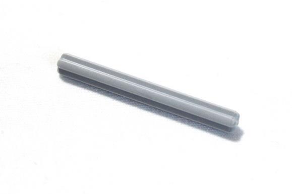
8 8 Name X Name X Name X Name X [HINT: These are 5M in size] Name X Name(s) X

9 9 Name X Name X Name X Name X Name X Name X

10 ACTIVITY < Axel cross section> 0 In this activity, we will look at the axel cross section more closely. Cross section is a view that would be obtained by making a straight cut through something, especially when the cut is at right angles to the axis. Here is an example of cross section of an orange.

11
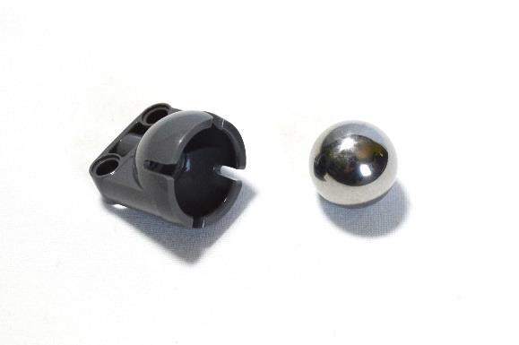
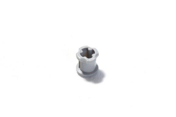
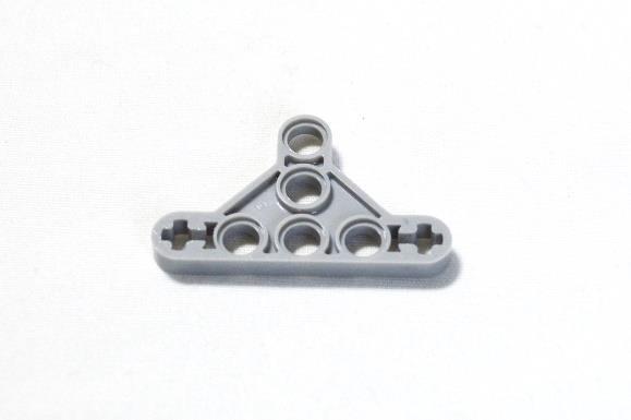
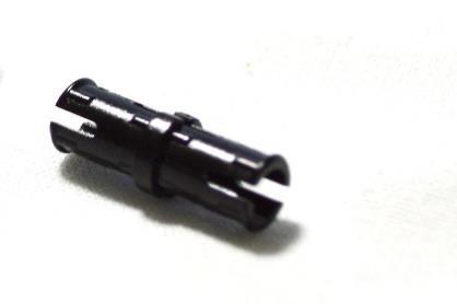
12 ACTIVITY < Build Cycle Bot > 2 In this activity, we will build a simple bot (simbot) that we can use as a starting point for other activities. This is a bare minimum design feel free to be creative and design a bot that you want. Find the following from your Mindstorms kit you may follow the steps provided in the accompanying document. X EV3 block 2 X large motors 2 X tires 2 X hubs 2 X 5M axles X steel ball X ball bearing X 2M Connector with friction 2 X M bushing 4 X 3M connection peg with friction 2 X cables X ½ triangle beam 2 X 2M connector peg with friction/axle


13 3 Step Place the Ball Bearing, Steel Ball, and the 2M peg as shown Step 2 2 The peg will be pushed at the top end of the Bearing Push the Steel Ball in the Bearing and place the parts as shown


14 4 Step 3 Push 2M peg on top of the Bearing Step 4 The Tires will be slipped over the Hubs Prepare the Hubs and the Tires for assembly

15 5 Step 5 The assembly must look like this Step 6 Flip the assembly so that the circular end shows on top 2 Place the axles for pushing them in the hub of the assembly
16 6 Step 7 Push the axles and get ready with the 2X M bushings 2 Bushings will be used as spacers here Step 8 Push the bushings in position


17 7 Step 9 Prepare the EV3 Block and 4X 3M pegs for assembly Step 0 Push the pegs in the vertical holes. The EV3 assembly will look similar


18 8 Step Place the EV3 Block and 2X large motors as shown Step 2 Attach the motor to the EV3 Block by aligning the holes with peg and giving a gentle push


19 9 Step 3 Attach the second motor to the EV3 like the first one Step 4 Place the parts as shown for assembly


20 20 Step 5 Push the tire as shown, note the axle is level of the collar Step 6 The bot will look as shown after attaching the two tires


21 2 Step 7 2 The cross side of the pegs will be pushed in the cross holes Prepare the shown parts for assembly Step 8 Push the pegs as shown


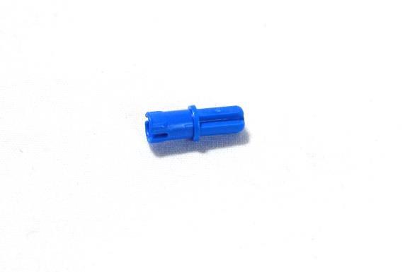
22 22 Step 9 Prepare the two components for assembly 2 The blue pegs will be pushed in the middle holes Step 20 2 The bearing assembly will be pushed on the first hole from bottom The blue pegs are pushed in the middle holes to attach the beam


23 23 Step 2 The bearing assembly is pushed in place Step 22 Connect the large motor ports with ports C and D to complete the bot

24 ACTIVITY < EV3 Software> 24 In this activity, the goal is to be able to find the EV3 software, start it, save a file, and finally reopen it. Step Find the Lego Mindstorms Application from Start Menu and launch it


25 25 Step 2 Add new project Step 3 The window will look similar

26 26 Step 4 Save project on your computer by clicking Save Project Give it a name Step 5 Project name changes Change program name by clicking
27 27 One project can have multiple programs. Click + sign to add new program Step 6 Locate the file on your computer where you saved it and open it. It is a good practice to save your programs in a folder where you can locate them and refer to them or reuse them for future use.

28 28 ACTIVITY < Calculating Distance Travelled > In this activity, our goal is to understand how to calculate the distance that our bot will travel for each revolution of the wheel. Next, we will calculate number of revolutions the bot wheel will be required to travel in order to achieve a certain distance. Step Measure the diameter of the wheel from your EV3 set. Use a scale that can measure in millimeters (mm) Diameter Diameter = Step 2 Calculate a value (let s call it Circumference) by multiplying 3.4 with the Diameter you found in step or Circumference = Diameter X 3.4 Thus Circumference = X 3.4


29 29 Circumference = Step 3 Cut a narrow strip of paper which is 0 mm in width and has a length of the value you calculated for the Circumference. 0 mm width Step 4 Take the strip from previous step and wrap it around a wheel from the EV3 set as shown below Length = Circumference value


30 30 Step 5 You will notice that the strip that you had created wraps the wheel perfectly. Which means that when the wheel makes one revolution it travels the distance which is calculated by the Circumference of the wheel. See the image below to see if you agree.
31 3 Step 6 This also means that if the wheel makes two revolutions then the bot will travel by a distance = 2 X Circumference and similarly for 3 revolutions distance = 3 X Circumference and so on. We also know that the Circumference is calculated by multiplying the value of pi which is 3.4 with the Diameter. We can see thus that DistanceTraveledByBot = 3. 4 X Diameter X NumberOfWheelRevolutions We can also calculate the number of wheel revolutions required if we know the distance that must be traveled by the bot by simply rearranging the above formula to: NumberOfWheelRevolutions = DistanceTraveledByBot 3. 4 X Diameter Step 7 Answer the following questions. You may plugin the values in the above formula for your answers. If you set the number of revolutions for the wheel to be 3 and your robot has wheels with diameter of 56 mm, how far will your robot travel? 2. Set the values of your program to have 3 revolutions of the wheel and then measure the distance that the bot moves
32 32 a. How close was this answer as compared to previous one? b. If it was different, what could have caused the difference? 3. Run the bot. If you want your bot to travel 200 mm and your robot has wheels with diameter of 56 mm, how many revolutions must your wheel make? NumberOfWheelRevolutions = 3. 4 X 4. If you want your bot to travel a distance of 500 mm and your robot has wheels with diameter of 56 mm, how many revolutions must your wheel make?
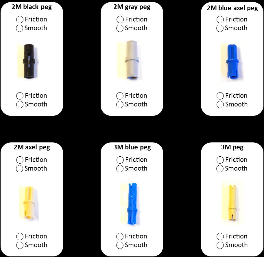
33 ACTIVITY < Connectors Smooth or With Friction> 33 The technics parts have different type of pins. In this activity, your goal is to explore the different types. Selecting the correct pin for the type of joint is important for a sturdy robot Step Find the following from your Mindstorms Kit: of 3M beam of 2M black peg of 2M gray peg of 2M blue axel peg of 2M gray axel peg of 3M blue peg of 3M gray peg Step 2 Push one side of the 2M black peg in a hole in 3M beam and then try to rotate the peg note if it rotates easily. Pull out the peg and now push the other side in a hole in 3M note if it rotates easily. Mark your findings in the picture below if the side offers a frictional joint or offers a smooth joint. Step 3 Repeat Step 2 with all other pegs that you selected in Step and mark your findings on next page. Mark Friction/Smooth for both top and bottom side of the pins.

34 34
35 ACTIVITY < Cross Pinning > 35 In this activity, we will make rectangular frames - we will cross pin using (i) rectangular or square shape, and (ii) triangular shape. Your goal will be to test which one of the two cross pinning makes sturdy frames. Find the following from your Mindstorms kit. 4 X 3M beams 8 X 7M beams 6 X 2M connection peg with friction

36 36 Step. Plug 8 X 2M pegs in two 3M beams as shown Step.2 Complete the frame using 4 X 7 M beams

37 37 Step 2. Plug 8 X 2M pegs in two 3M beams as shown Step 2.2 Complete the frame using 4 X 7 M beams

38 38 Step 3- Answer the questions below Frame cross pinned using rectangular shape Frame cross pinned using triangular shape Which of the two frames are more stable when you apply force near the position of the arrows? Support your previous answer by explaining what you think makes the frame you selected sturdy.

39 ACTIVITY < simbot > 39 In this activity, we will build a simple bot (simbot) that we can use as a starting point for other activities. This is a bare minimum design feel free to be creative and design a bot that you want to. Find the following from your Mindstorms kit you may follow the steps provided in the accompanying document. X EV3 block 2 X large motors 2 X tires 2 X hubs 2 X 5M axles X steel ball X ball bearing 2 X M bushing 8 X 3M connection peg with friction 2 X 5x7M frames X 5x frame


40 40 Step 2 Place the 5X7 M Frame as shown Place the two large motors on a flat surface 3 Take 4 blue 3M connector pegs for locking the frame onto motors Step 2 Lock the frame onto motors with 4 pegs


41 4 Step 3 Turn the motor assembly upside down 2 Prepare a 9M beam by partially inserting 2 3M frictional pegs 3 The 9M beam will help support the two motors for a sturdy join Step 4 Join the 9M beam as shown and support with 2 additional 3M pegs


42 42 Step 5 2 Rotate the assembly upside down again Prepare a 7M beam by partially inserting 2 3M frictional pegs this will hold the third wheel built with steel ball and the bearing 3 The 7M beam will be attached to the 5X7M frame to hold the third wheel built with steel ball and the bearing Step 6 Attach the 7M beam and press the pegs into position


43 43 Step 7 Place the large motor assembly as shown 3 Select two 3M pegs with friction to attach the selected frame to the motors 2 Place the 5XM frame. This will support the EV3 block when positioned on motors Step 8 2 Attach the selected frame to the motors with pegs Place the 5XM frame in position as shown


44 44 Step 9 2 EV3 bock will be placed on the motors; the pegs will join the block and the 5XM frame Rotate the free end of 5XM frame it will attach to the EV3 block when in position Step0 Attach to the EV3 block and the frame with pegs


45 45 Step Turn the assembly as shown 2 The bottom two holes on frame will Place the 5X7M frame and 2 3M pegs as shown 3 be pushed on these pegs Step 2 2 With two pegs attach the frame to the EV3 block Press the frame on to the pegs

46 46 Step 3 Get the hubs and the tires ready for assembly Step 4 Insert the 5M axles from the circular hole side of the hub


47 47 Step 5 Add M bushings on the axles as spacers Step 6 The assembly of tires should look as shown


48 48 Step 7 Attach the tires to the motors Step 8 Get the steel ball and bearing assembly ready


49 49 Step 9 Attach the steel ball and bearing assembly on the 7M beam using the pegs Step 20 The third wheel should look similar as shown

50 50 Step 2 Connect the motors and the ports B & C on EV3 block with cables
51 ACTIVITY < Move Steering > 5 Section In this section, you will first look at the drawing and try to answer what do you expect the bot will do. In the next step you will answer what did you find by programming your bot. Activity What do you expect? The bot will move Forward Backward Left Right The distance travelled by the bot is controlled by: Wheel rotation o Time The power is: Low Medium o High The bot moved Forward Backward Left What did you find? Right The distance travelled by the bot was controlled by: Wheel rotation o Time The power was: Low Medium o High
52 52 What will bot do after performing the steering instruction? o Braked immediately o Slowly stopped as it lost momentum Activity 2 What did bot do after performing the steering instruction? o Braked immediately o Slowly stopped as it lost momentum What do you expect? The bot will move Forward Backward Left Right The distance travelled by the bot is controlled by: Wheel rotation o Time The power is: Low Medium o High What will bot do after performing the steering instruction? o Braked immediately o Slowly stopped as it lost momentum The bot moved Forward Backward Left What did you find? Right The distance travelled by the bot was controlled by: Wheel rotation o Time The power was: Low Medium o High What did bot do after performing the steering instruction? o Braked immediately o Slowly stopped as it lost momentum
53 53 Activity 3 What do you expect? The bot will move Forward Backward Left Right The distance travelled by the bot is controlled by: Wheel rotation o Time The power is: Low Medium o High What will bot do after performing the steering instruction? o Braked immediately o Slowly stopped as it lost momentum The bot moved Forward Backward Left What did you find? Right The distance travelled by the bot was controlled by: Wheel rotation o Time The power was: Low Medium o High What did bot do after performing the steering instruction? o Braked immediately o Slowly stopped as it lost momentum
54 54 Activity 4 What do you expect? The bot will move Forward Backward Left Right The distance travelled by the bot is controlled by: Wheel rotation o Time The power is: Low Medium o High What will bot do after performing the steering instruction? o Braked immediately o Slowly stopped as it lost momentum The bot moved Forward Backward Left What did you find? Right The distance travelled by the bot was controlled by: Wheel rotation o Time The power was: Low Medium o High What did bot do after performing the steering instruction? o Braked immediately o Slowly stopped as it lost momentum


55 55 Activity 5 What do you expect? The bot will move Forward Backward Left Right The distance travelled by the bot is controlled by: Wheel rotation o Time The power is: Low Medium o High What will bot do after performing the steering instruction? o Braked immediately o Slowly stopped as it lost momentum The bot moved Forward Backward Left What did you find? Right The distance travelled by the bot was controlled by: Wheel rotation o Time The power was: Low Medium o High What did bot do after performing the steering instruction? o Braked immediately o Slowly stopped as it lost momentum
56 56 Section 2 In this section, you are given a scenario and your goal is to program the bot to make that action. Scenario : The bot moves Forward by 3 wheel rotations and then stops by braking Scenario 2: The bot moves Forward by 3 wheel rotations and then stops by braking Scenario 3: The bot moves Forward by 3 wheel rotations and then stops by braking Scenario 4: The bot moves Forward by 3 wheel rotations and then stops by braking Scenario 5: The bot moves Forward by 3 wheel rotations and then stops by braking

57 ACTIVITY < Three Gear Drive > 57 In this activity, we will explore meshing gears we will observe how the direction of the driven gear is opposite to the driver gear. Create a gear assembly as shown below You will need the following parts 3 X 24-tooth gears 3 X 2M connector peg with axle X 3M beam
58 58 Answer the questions below Gear Gear 2 Gear 3 If Gear is rotated in clockwise direction, fill in the following blanks?. Gear 2 rotates in direction. 2. Gear 3 rotates in direction.
59 ACTIVITY < Gear Claw > 59 In this activity, we will make an assembly that is like a crab claw. The claw opening and closing is synchronized using gears. Additionally, the claws are opened and closed by subjecting an axle to a torque. You will need the following parts 2 X 24-tooth gears X 8-tooth gear 6 X ½ M bushings 2 X 6M axles X 2M axle X 0M axle X 9M beam 2 X 4x4 angular beam


60 60 Step Arrange the two 6M axles and other parts as shown Step 2 Assemble the parts as shown

61 6 Step 3 Arrange the 2M axle and other parts as shown Step 4 Assemble the parts as shown


62 Step 5 62 Arrange the parts as shown Step 6 Assemble the parts as shown


63 63 Step 7 Arrange the parts as shown Step 8 Slide the ½ M bushings on the axles
64 64 You can apply torque to this axle and open and close the claw
 of the driven gear equals gear ratio time the RPM of the driver gear.")
65 ACTIVITY < Gear Ratio > 65 Let s define the term gear ratio: gear ratio is the number of teeth of the driver gear to the number of teeth of the driven (follower) gear. In addition, the revolutions per minute (RPM) of the driven gear equals gear ratio time the RPM of the driver gear. Thus GearRatio = NumberOfTeethOfDriver NumberOfTeethOfDriven RPM Driven = GearRatio RPM Driver Consider an example case below, gear one has 24 teeth and gear two has 40 teeth. Additionally, gear one which is the driver gear has an RPM of 0 if we were to calculate the RPM of gear 2 we will follow the following steps: Gear ratio = and RPM Gear2= * 0 = 6 That is for every 0 revolutions of gear, gear 2 will have 6 revolutions.

66 66 Answer the questions below ) Once again gear one has 24 teeth and gear two has 40 teeth. Gear one is the driver gear has an RPM of 20 calculate the RPM of gear 2: Gear ratio = and RPM Gear2 = Thus, for every 20 revolutions of gear, gear 2 will have revolutions. 2) Once again gear one has 24 teeth and gear two has 40 teeth. However, gear two is the driver gear and it has an RPM of 0 calculate the RPM of gear : Gear ratio = and RPM Gear = * 0 = Thus, for every 0 revolutions of gear 2, gear will have revolutions.

67 67 ACTIVITY < Fork Attachment > A worm gear is a screw that turns a spur gear with its axle at right angle. A worm gear creates a high gear ratio. Each time the worm gear shaft spins one revolution, the spur gear moves one tooth forward. The worm gear has an unusual advantage of self-locking - you can turn the worm gear shaft to drive the output shaft, but you cannot turn the output shaft to drive the worm gear shaft. In this activity, we will create a fork attachment that can be powered up or down by applying torque to the axel of the assembly. The final bot will look like the one shown below.
68 68 Find the following from your Mindstorms kit (refer to the EV3 parts list for identifying shapes with names) you may follow the steps provided in following pages. 2 X 9 M beams 2 X 4x4M angular beams 4 X 2M peg with friction X 4-tooth gear X worm gear X 2M axle X 24-tooth gear 2 X 3M cross blocks 2 X 3x7M double angular beam 4 X 3M connection peg with friction 2 X 2x4 angular beams 2 X ½ triangle beam 5x3M 4 X ½ M bushing 2 X M bushing 2 X 7M axles X 5M axle


69 69 Step Arrange the 7M axel and other parts as shown Step 2 Assemble the worm gear on the axle and slide ½ M bushings from two sides 2 Place two 3M cross blocks as shown 3 The end of the axles will slide into the circular hole

70 70 Step 3 The end of the axle is slid into the circular hole Step 4 Arrange the 7M axel and the 24-tooth gear as shown


71 Step 5 7 Slide the 24-tooth gear on the axel Step 6 Arrange the 5M axel and other parts as shown


72 Step 7 72 Slip the triangle beams on the two sides of the gear axel 2 In next step the two ends of the worm gear assembly will slide between arrow marked sides of triangle Step 8 Place the two ends of the worm gear assembly and lock as shown using 2M axle


73 73 Step 9 Lock the other end of the assembly with 5M axel and arrange 2 X 2M bushings, and 2X ½ M bushings as shown Step 0 Slide the 2 X 2M bushings, and 2X ½ M bushings as shown


74 74 Step Arrange the assembly and the 4-tooth gear as shown Step 2 Slip the 4-tooth gear as shown 2 Try to rotate this gear and notice how the 24-tooth gear rotates. Note that you cannot rotate the 24-tooth gear to rotate the worm gear.


75 75 Step 3 Arrange parts as shown Step 4 Join the beams as shown


76 Step This end of the beams will slide on the axles in the next step Arrange the beams with the assembly as shown Step 6 Slide the beam ends on the axle


77 77 Step 7 Rotate the 4-tooth gear to make the assembly flat and balanced as shown Step 8 Arrange the parts as shown


78 78 Step 9 Arrange the parts as shown Step 20 Join the beams as shown

79 79 Step 2 Arrange the parts as shown 2 This end of the beams will slide on the axles in the next step Step 22

80 80 ACTIVITY < dsbot > In this activity, we will modify the simbot by adding a drive shaft (we will call it dsbot) so that powered attachments such as lifting forks can be supported by this bot be creative and add to the design if you want. Drive shaft that can be used to take-off power for attachments such as lifting forks etc.


81 8 Powered drive shaft Find the following from your Mindstorms kit you may follow the steps below. X 4 tooth gear 2 X M bushing X medium motor X 4M axle 4 X 3M connection peg with friction Step Arrange the parts as shown

82 82 Step 2 Insert the axle in the motor Step 3 Push the two M bushings and 4 tooth gear on the axle


83 83 Step 4 Position the motor assembly, simbot, and 4 3M connector pegs as shown Step 5 Motor is locked in positioned using the pegs View from side View from front

84 84 Step 6 Connect the motor port and EV3 port A with 35 cm cable
85 ACTIVITY < forkbot > 85 In this activity, we will take the dsbot and attach the fork attachment. We call it forkbot You will need the following assemblies and parts dsbot forkattachment 2 X 3M peg with friction X 0M axle


86 86 Step Arrange the dsbot, the forkattachment, pegs, and axle shown 2 The assembly holes will align in position as marked by the arrows. The top hole will use 3M pin for locking, and the bottom hole will be attached with the axle. Step 2 The assembly is made using 3M pin in top hole for locking, and axel in the bottom holes. See close-up in next image


87 87 Notice how 4-tooth gears mesh for power transmission When the axles that need turning meet at an angle - usually a right angle they are called bevel gear
88 88 ACTIVITY < Engineering Design Process > Problem solving is a fun and creative process where we can apply technology to create solutions that meet the defined set of needs. A process called an Engineering Design Process can immensely help in meeting our desired goals. The Engineering Design Process guides us through a step-by-step method for finding solutions, these steps include (i) Identify the need & constraints (vii) Redesign as needed (ii) Research the problem (vi) Test and evaluate prototype (iii) Develop possible solutions (v) Build a prototype (iv) Select a promising solution
89 89 Think about the Maze challenge that you worked on and write down if there were tasks that you performed during that activity that fall under the different steps of the Engineering Design Process.. Identify the need & constraints what are our needs, and what is the problem that we are trying to solve? 2. Researching the problem find what is known about the problems, how others have tried to solve this problem, are their similar problems that may have a solution that we can use as an inspiration? 3. Develop possible solutions think about how you may solve the problem, discuss with your team members and mentors, draw your ideas on the paper, draw on a computer, write your ideas. Create many different possible solutions
90 90 4. Select a promising solution from the solutions that you designed in the previous step, select one that will most likely solve the problem best 5. Build a prototype start bringing your idea into a reality, for example if the solution is building a robot then build a robot 6. Test and evaluate prototype test to see if the prototype can solve the problem that you had defined. Write down the things that it does well and things that it does not do well
91 9 7. Redesign as needed Using your observations about what worked well and what did not work well, make changes to your solution. Repeat the steps to improve your solution over time

92 ACTIVITY < Touch Sensor > 92 A touch Sensor is a simple tool that can be used as a button, an obstacle sensor, or to count the number of presses of the button. You can use the button to start or stop something. In this activity, we will use it to find when the bot hits an obstacle. Find the following from your Mindstorms kit (refer to the EV3 parts list for identifying shapes with names) follow the steps provided in following pages. X touch sensor 2 X 2x4M angular beams 4 X 3M peg with friction X 4M axel 2 X 3X3 angular connector peg X 2M axle cable

93 93 Step Insert the axel in the cross hole of the touch sensor Step 2 Arrange the parts as shown for making side brackets
94 94 Step 3 Insert the 2M pegs as shown Step 4 Attach the angular beams as shown


95 95 2 Step 5 The square hole will be pushed on the axel Arrange the subassemblies as shown Step 6 The square holes are pushed on the axel


96 96 Step 7 Attach the cable as shown Step 8 The touch sensor assembly pegs will be inserted in these holes of the bot built in simbot activity

97 97 Step 9 2 Connect the other end of the cable in port The touch sensor assembly pegs are inserted in these holes

98 98 ACTIVITY < Ultrasonic Sensor > The challenge is shown using the image below. The bot must navigate through the maze from the starting position to the ending position. In the first case the robot will turn before hitting a wall. Find the following from your Mindstorms kit (refer to the EV3 parts list for identifying shapes with names) follow the steps provided in following pages. X ultrasonic sensor 2 X 2x4M angular beams 4 X 3M peg with friction X 4M axel 2 X 3X3 angular connector peg X 2M axle cable

99 99 Step Insert the axel in the cross hole of the sensor Step 2 Arrange the parts as shown for making side brackets


100 00 Step 3 Insert the 2M pegs as shown Step 4 Attach the angular beams as shown


101 0 2 Step 5 The square hole will be pushed on the axel Arrange the subassemblies as shown Step 6 The square holes are pushed on the axel


102 02 Step 7 Attach the cable as shown Step 8 The touch sensor assembly pegs will be inserted in these holes of the bot built in simbot activity

103 03 Step 9 2 Connect the other end of the cable in port 4 The sensor assembly pegs are inserted in these holes
104
How to Build with the Mindstorm Kit
 How to Build with the Mindstorm Kit There are many resources available Constructopedias Example Robots YouTube Etc. The best way to learn, is to do Remember rule #1: don't be afraid to fail New Rule: don't
Smart Spinner. Age 7+ Teacher s Notes. In collaboration with NASA
 Smart Spinner Age 7+ Teacher s Notes In collaboration with NASA LEGO and the LEGO logo are trademarks of the/sont des marques de commerce de/son marcas registradas de LEGO Group. 2012 The LEGO Group. 190912
Reliable Reach. Robotics Unit Lesson 4. Overview
 Robotics Unit Lesson 4 Reliable Reach Overview Robots are used not only to transport things across the ground, but also as automatic lifting devices. In the mountain rescue scenario, the mountaineers are
What Are Gears? What Do They Do?
 What Are Gears? What Do They Do? Pre-Lesson Quiz 1. What is a gear? 2. List as many examples as you can of gears or objects that use gears. 2 Pre-Lesson Quiz Answers 1. What is a gear? A gear is a wheel
LEGO Education WeDo 2.0 Toolbox
 LEGO Education WeDo 2.0 Toolbox WeDo 2.0 Table of Contents Program with WeDo 2.0 3-21 Build with WeDo 2.0 22-36 Program with WeDo 2.0 Programming is an important part of twenty-first century learning,
Applications in Design & Engine. Analyzing Compound, Robotic Machines
 v2.1 Compound Machines ering Applications in Design & Engine Analyzing Compound, Robotic Machines Educational Objectives At the conclusion of this lesson, students should be able to: Understand the relationship
Unit 1 Introduction to VEX and Robotics
 Unit Overview Unit 1 Introduction to VEX and Robotics VEX lab kits bring robotics into the classroom, making it a fun and educational experience for all. In this introductory unit, you review the kit and
Robotic Vehicle Challenge
 Robotic Vehicle Challenge Hello and welcome to your first team challenge! Within this document you will find information about what to expect and prepare for to be successful in your first challenge. In
2. Explore your model. Locate and identify the gears. Watch the gear mechanism in operation as you turn the crank.
 Experiment #1 79318 Using a Spur Gear System in a Crank Fan Objectives: Understand and describe the transfer of motion through a spur gear system and investigate the relationship between gear size, speed
Deriving Consistency from LEGOs
 Deriving Consistency from LEGOs What we have learned in 6 years of FLL by Austin and Travis Schuh Objectives Basic Building Techniques How to Build Arms and Drive Trains Using Sensors How to Choose a Programming
BASIC BUILDING TIPS. Building Tips TABLE OF CONTENTS. Forward 3 plates, beams, Connectors, 5 Bracing and Interlocking 6
 BASIC BUILDING TIPS last updated: June 25 th, 2015 TABLE OF CONTENTS Forward 3 plates, beams, Connectors, 5 Bracing and Interlocking 6 Basics on Gears 8 Types of gears 8 Gears Spacing 9 Simple Gear Ratio
CONTENTS PROJECT IDEAS 4 ROBO 1 6 ROBO 2 9 PATHFINDER 1 13 PATHFINDER 2 15 ACROBOT 1 17 ACROBOT 2 20 SPECIAL FEATURES. Movement 26.
 The Constructopedia is a building guide for the Robotics Invention System that offers suggestions, hints, and tips to get you started on the CD-ROM Challenges and robotic inventions of your own design.
WeDo 2.0. Science & Technologies. Effectively implement the. Freecall:
 Effectively implement the Science & Technologies Australian Curriculum Learn important skills in problem solving and technical skills such as coding right from their Early Years. A new national curriculum
EV3 Motors. EV3 Gyro Sensor. NXT Touch Sensors. EV3 Color Sensor. NXT Light Sensors. EV3 Touch Sensor. NXT Sound Sensor. EV3 Ultrasonic Sensor
 Sensors EV3 Gyro Sensor EV3 Color Sensor EV3 Touch Sensor EV3 Ultrasonic Sensor NXT Ultra Sonic Sensors EV3 Motors NXT Touch Sensors NXT Light Sensors NXT Sound Sensor NXT Color Sensors Core Parts Core
Grade 8 Science. Unit 4: Systems in Action
 Grade 8 Science Unit 4: Systems in Action Machines That Turn Last class we looked at the idea of a boat winch, a wheel and axle used to get a boat out of the water, onto a trailer. You rotate the handle
Autodesk's VEX Robotics Curriculum. Unit 10: Drivetrain Design 2
 Autodesk's VEX Robotics Curriculum Unit 10: Drivetrain Design 2 1 Overview In Unit 10: Drivetrain Design 2, you design your own drivetrain, building on knowledge and skills from previous units. You also
MECHANISMS. AUTHORS: Santiago Camblor y Pablo Rivas INDEX
 MECHANISMS AUTHORS: Santiago Camblor y Pablo Rivas INDEX 1 INTRODUCTION 2 LEVER 3 PULLEYS 4 BELT AND PULLEY SYSTEM 5 GEARS 6 GEARS WITH CHAIN 7 WORM GEAR 8 RACK AND PINION 9 SCREW AND NUT 10 CAM 11 ECCENTRIC
Something to use as a ramp (preferably a flat surface that would enable the buggy to roll for 25 cm or more) STUDENT PAGES.
 STUDENT PAGES.") Design a Lunar Buggy OBJECTIVE To demonstrate an understanding of the Engineering Design Process while utilizing each stage to successfully complete a team challenge. PROCESS SKILLS Measuring, calculating,
Design a Lunar Buggy OBJECTIVE To demonstrate an understanding of the Engineering Design Process while utilizing each stage to successfully complete a team challenge. PROCESS SKILLS Measuring, calculating,
LEGO Parts Guide. Naming and Building with LEGO parts. Version 1.3 4/12/10
 LEGO Parts Guide Naming and Building with LEGO parts Version 1.3 4/12/10 Table of Contents Connectors... 4 Friction Pegs... 4 Frictionless Pegs... 5 Ball Joints / Tie Rods... 6 Bushings... 7 Angle Connectors...
10 STEM Electric Car Assessment Task Name
 10 STEM Electric Car Assessment Task Name Step 1 identify parts. Collect a piece of corflute and an electric car kit. Open your electic car kit components. We will be using all of the pieces, except the
Robotics. BEGINNERS: Mondays 4:00 to 5:15 PM April 10 to June 12 LEVEL 3: Thursdays 4:00 to 5:15 PM April 20 to June 8
 Robotics 3 & 4 Intro to Robotics (co-ed) Help your child develop science, math, and teamwork skills through building and basic programming with LEGO Smarthub 2 I/O robots. Children in higher levels will
IT'S MAGNETIC (1 Hour)
") IT'S MAGNETIC (1 Hour) Addresses NGSS Level of Difficulty: 4 Grade Range: 3-5 OVERVIEW In this activity, students will create a simple electromagnet using a nail, a battery, and copper wire. They will
IT'S MAGNETIC (1 Hour) Addresses NGSS Level of Difficulty: 4 Grade Range: 3-5 OVERVIEW In this activity, students will create a simple electromagnet using a nail, a battery, and copper wire. They will
What Is an Electric Motor? How Does a Rotation Sensor Work?
 What Is an Electric Motor? How Does a Rotation Sensor Work? Electric Motors Pre-Quiz 1. What is an electric motor? 2. Name two applications (things) you use every day that use electric motors. 3. How does
Competitive VEX Robot Designer
 Competitive VEX Robot Designer Skill Set 2: Builder I Terminal Objective 2.2: construct a boom crane Performance Objective: Given provided VEX components, construct a boom crane that extends a minimum
8.6 Investigating gear ratios using LEGO
 Tony Ford Science Monday, 1 December 2014 Page 1 8.6 Investigating ratios using LEGO Aim To investigate the relationship between speed of a wheel and the number of teeth on each connected to it? Discussion
Technology Exploration-I Curriculum Development Unit
 Technology Exploration-I Modu le 4: Pulleys and Gears PREPARED BY Curriculum Development Unit August 2013 Applied Technology High Schools, 2013 Module 4: Pulleys and Gears Module Objectives After the completion
BEGINNER EV3 PROGRAMMING LESSON 1
 BEGINNER EV3 PROGRAMMING LESSON 1 Intro to Brick and Software, Moving Straight, Turning By: Droids Robotics www.ev3lessons.com SECTION 1: EV3 BASICS THE BRICK BUTTONS 1 = Back Undo Stop Program Shut Down
Module 3: Wheel & Axle
 Technology Exploration-I Module 3: Wheel & Axle PREPARED BY Curriculum Development Unit August 2013 Applied Technology High Schools, 2013 Module 3: Wheel & Axle Module Objectives After the completion of
THE LEGO MINDSTORMS NXT ZOO! an unofficial, kid-friendly guide to building robotic animals with LEGO MINDSTORMS NXT. fay rhodes
 THE LEGO MINDSTORMS NXT ZOO! an unofficial, kid-friendly guide to building robotic animals with LEGO MINDSTORMS NXT fay rhodes 5 spiderbot: an NXT spider Spiderbot is a walking eight-legged spider that
Compound Gears Laboratory - Part 2
 Compound Gears Laboratory - Part 2 Names: Date: About this Laboratory In this laboratory, you will explore compound gear trains, gear ratios, and how the number of teeth on a drive and driven gear affect
Simple Gears and Transmission
 Simple Gears and Transmission Simple Gears and Transmission page: of 4 How can transmissions be designed so that they provide the force, speed and direction required and how efficient will the design be?
Teaching Aids and Materials: This week the students will: Standards addressed and expectations of Students for the week:
 Teacher: Subject Area: Room No: William Schraer STEM - Intro to Engineering Design 513 Lesson Week: Meeting Time Period: Day: February 2 February 6 1..5..7.. Wednesday 4 th Teaching Aids and Materials:
Introduction to Elementary and Middle School Robotics. John Heffernan 8/17/2014
 Introduction to Elementary and Middle School Robotics John Heffernan 8/17/2014 Introduction Elementary and Middle School Engineering Education with a focus on robotics Some background Activities Wrap-Up
ROBOT C CHALLENGE DESIGN DOCUMENT TEAM NAME. Sample Design Document. Bolt EVA. Lightning. RoboGirls. Cloud9. Femmebots
 ROBOT C CHALLENGE DESIGN DOCUMENT TEAM NAME (SELECT TEAM NAME TO NAVIGATE TO THE TEAM S DESIGN DOCUMENT) Sample Design Document Bolt EVA Lightning RoboGirls Cloud9 Femmebots SAMPLE ROBOT C DESIGN DOCUMENT
VEX IQ Curriculum: Let s Get Started
 VEX IQ Curriculum: Let s Get Started Let s Get Started Student Handout Using VEX IQ Hardware The VEX IQ platform kits provide easy, fun, and accessible tools to teach and learn all four legs of STEM, no
Exploration 2: How Do Rotorcraft Fly?
 Exploration 2: How Do Rotorcraft Fly? Students choose a model and use it to explore rotorcraft flight. They use a fair test and conclude that a spinning rotor is required for a rotorcraft to fly. Main
M3 Design Product Teardown Kobalt Double-Drive Screwdriver
 19 Jun, 2013 Why do the product teardowns? M3 Design Product Teardown Kobalt Double-Drive Screwdriver Part of the product development process is to apply knowledge gained from prior experience during the
Lifting Mechanisms. Example 1: Two Stage Lift
 Lifting Mechanisms The primary scoring method for the 2018 game is to deposit fuel cubes into scoring zones. A manipulator fixed to your robot can deliver fuel cubes into ground level scoring zones, but
Electromagnets ENERGY USE AND DELIVERY LESSON PLAN 3.3. Public School System Teaching Standards Covered
 ENERGY USE AND DELIVERY LESSON PLAN 3.3 Electromagnets This lesson is designed for 3rd 5th grade students in a variety of school settings (public, private, STEM schools, and home schools) in the seven
Exploration 4: Rotorcraft Flight and Lift
 Exploration 4: Rotorcraft Flight and Lift Students use appropriate terminology to describe the various stages of flight and discover that the lift force changes with the amount of air moved by the rotor
APPENDIX A: Background Information to help you design your car:
 APPENDIX A: Background Information to help you design your car: Solar Cars: A solar car is an automobile that is powered by the sun. Recently, solar power has seen a large interest in the news as a way
Autodesk's VEX Robotics Curriculum. Unit 9: Drivetrain Design 1
 Autodesk's VEX Robotics Curriculum Unit 9: Drivetrain Design 1 1 Overview In Unit 9: Drivetrain Design 1, you learn the basic principles of drivetrain design, build a basic VEX drivetrain, and test your
Your web browser (Safari 7) is out of date. For more security, comfort and. the best experience on this site: Update your browser Ignore
 is out of date. For more security, comfort and. the best experience on this site: Update your browser Ignore") Your web browser (Safari 7) is out of date. For more security, comfort and Activitydevelop the best experience on this site: Update your browser Ignore Circuits with Friends What is a circuit, and what
Your web browser (Safari 7) is out of date. For more security, comfort and Activitydevelop the best experience on this site: Update your browser Ignore Circuits with Friends What is a circuit, and what
Amazing127_RobotCDesignDoc
 Amazing127_RobotCDesignDoc Specifications: -Length 6.6 in -Width 9.7 in -Height 6.6 in Pictures of our robot: Left Side Back Side Right Side Front Side Componets: 1 Small Motor 2 Large Motors 1 Touch Sencor
CHAPTER 6 GEARS CHAPTER LEARNING OBJECTIVES
 CHAPTER 6 GEARS CHAPTER LEARNING OBJECTIVES Upon completion of this chapter, you should be able to do the following: Compare the types of gears and their advantages. Did you ever take a clock apart to
Vehicle of Revolution: How many turns will it take?
 Vehicle of Revolution: How many turns will it take? A SMART project; Funded by the National Science Foundation Polytechnic University Mechatronics Department Headed by Professor Vikram Kapila Group 2:
Rubber Band Car. Tommy Stewart Corey Marineau John Martinez
 Tommy Stewart Corey Marineau John Martinez Rubber Band Car PURPOSE: Create a rubber band propelled car that will travel three meters. Then create a regression line using the data that represents how the
Rocket Races. Rocket Activity. Objective Students investigate Newton s third law of motion by designing and constructing rocketpowered
 Rocket Activity Rocket Races Objective Students investigate Newton s third law of motion by designing and constructing rocketpowered racing cars. National Science Content Standards Unifying Concepts and
ECSE-2100 Fields and Waves I Spring Project 1 Beakman s Motor
 Names _ and _ Project 1 Beakman s Motor For this project, students should work in groups of two. It is permitted for groups to collaborate, but each group of two must submit a report and build the motor
Driver Driven. InputSpeed. Gears
 Gears Gears are toothed wheels designed to transmit rotary motion and power from one part of a mechanism to another. They are fitted to shafts with special devices called keys (or splines) that ensure
2010 National Edition correlated to the. Creative Curriculum Teaching Strategies Gold
 2010 National Edition correlated to the Creative Curriculum Teaching Strategies Gold 2015 Big Day for PreK is a proven-effective comprehensive early learning program that embraces children's natural curiosity
Scholastic Big Day for PreK. Arkansas Early Childhood Education Framework for Three & Four Year Old Children 2011
 Scholastic Big Day for PreK Correlated to the Arkansas Early Childhood Education Framework for Three & Four Year Old Children 2011 TM & Scholastic Inc. All rights reserved. SCHOLASTIC, Big Day for PreK,
Motion Commotion, L1, Activity 1:Differential Gears
 Motion Commotion, L1, Activity 1:Differential Gears Subject Area Measurement Associated Unit Mechanics Mania Associated Lesson Motion Commotion Activity Title Differential Gears Header Insert image 1 here,
Fourth Grade. Multiplication Review. Slide 1 / 146 Slide 2 / 146. Slide 3 / 146. Slide 4 / 146. Slide 5 / 146. Slide 6 / 146
 Slide 1 / 146 Slide 2 / 146 Fourth Grade Multiplication and Division Relationship 2015-11-23 www.njctl.org Multiplication Review Slide 3 / 146 Table of Contents Properties of Multiplication Factors Prime
LETTER TO PARENTS SCIENCE NEWS. Dear Parents,
 LETTER TO PARENTS Cut here and paste onto school letterhead before making copies. Dear Parents, SCIENCE NEWS Our class is beginning a new science unit using the FOSS Magnetism and Electricity Module. We
Simple Gears and Transmission
 Simple Gears and Transmission Contents How can transmissions be designed so that they provide the force, speed and direction required and how efficient will the design be? Initial Problem Statement 2 Narrative
Solar Matters III Teacher Page
 Solar Matters III Teacher Page Junior Solar Sprint Wheels, Axles & Bearing Student Objective The student: given a scenario of a design with wheels, will be able to predict how the design will function
ELECTRICITY ELECTRICITY. Copyright 2016 Cyber Innovation Center. All Rights Reserved. Not for Distribution.
 TEACHER STUDENT EDITION MANUAL ELECTRICITY ELECTRICITY www.nicerc.org Welcome to STEM EDA! STEM Explore, Discover, Apply (STEM EDA) is designed as a three course progression through STEM (science, technology,
MiSTE STEM Camp Solar Lesson July, 2016 Standard(s) Learning targets Assessment Essential vocabulary. Informal - Discussion and participation
 Learning targets Assessment Essential vocabulary. Informal - Discussion and participation") MiSTE STEM Camp Solar Lesson July, 2016 Standard(s) Learning targets Assessment Essential vocabulary Science SEPS.1 - I can clarify problems to determine criteria for possible solutions. Science SEPS.8
MiSTE STEM Camp Solar Lesson July, 2016 Standard(s) Learning targets Assessment Essential vocabulary Science SEPS.1 - I can clarify problems to determine criteria for possible solutions. Science SEPS.8
Propeller Palooza! A classroom design challenge for students
 National Aeronautics and Space Administration Propeller Palooza! A classroom design challenge for students Four to Soar Aerodynamics Unit Table of Contents Lesson Objectives, Concepts, and Standards 2
Engaging Inquiry-Based Activities Grades 3-6
 ELECTRICITY AND CIRCUITS Engaging Inquiry-Based Activities Grades 3-6 Janette Smith 2016 Janette Smith 2016 1 What s Inside Activity 1: Light it Up!: Students investigate different ways to light a light
Topic: Friction. Planes, Trains, and Automobiles. A Poppins Book Nook Science Experiment. My Name Is:
 Planes, Trains, and Automobiles A Poppins Book Nook Science Experiment Topic: Friction My Name Is: ---------------------------------------------------------------------------------------------------------
Electricity and. Circuits Science Unit 1. For Special Education. Created by Positively Autism. Hands-On Low Prep Easy to Use
 Electricity and Circuits Science Unit 1 For Special Education Hands-On Low Prep Easy to Use Created by Positively Autism Making Learning Fun and Meaningful for Children with Autism Thank You for Downloading
Chapter 1. Stair-Climber. Doug Carlson
 Chapter 1 Stair-Climber Doug Carlson 1 2 Chapter # Chapter Title Bill of Materials These are the parts you will need to build the Stair-Climber as shown. Introduction Stair-Climber is the latest in a series
The Car Tutorial Part 2 Creating a Racing Game for Unity
 The Car Tutorial Part 2 Creating a Racing Game for Unity Part 2: Tweaking the Car 3 Center of Mass 3 Suspension 5 Suspension range 6 Suspension damper 6 Drag Multiplier 6 Speed, turning and gears 8 Exporting
Lesson Plan: Electricity and Magnetism (~100 minutes)
") Lesson Plan: Electricity and Magnetism (~100 minutes) Concepts 1. Electricity and magnetism are fundamentally related. 2. Just as electric charge produced an electric field, electric current produces a
Lesson Plan: Electricity and Magnetism (~100 minutes) Concepts 1. Electricity and magnetism are fundamentally related. 2. Just as electric charge produced an electric field, electric current produces a
For 8-12 Year Olds. Fantastic Gears. Premium Worksheets For Children. Content: Marwah Illustrations: Dikhit Borah
 For 8-12 ear Olds Fantastic Gears Premium Worksheets For Children Content: Marwah Illustrations: Dikhit Borah Index Activity Name Skills Acquired Types of Gears Missing Gears Geared Vehicles Get In Gear!
Moments. It doesn t fall because of the presence of a counter balance weight on the right-hand side. The boom is therefore balanced.
 Moments The crane in the image below looks unstable, as though it should topple over. There appears to be too much of the boom on the left-hand side of the tower. It doesn t fall because of the presence
Fourth Grade. Slide 1 / 146. Slide 2 / 146. Slide 3 / 146. Multiplication and Division Relationship. Table of Contents. Multiplication Review
 Slide 1 / 146 Slide 2 / 146 Fourth Grade Multiplication and Division Relationship 2015-11-23 www.njctl.org Table of Contents Slide 3 / 146 Click on a topic to go to that section. Multiplication Review
Introduction: Problem statement
 Introduction: Problem statement The goal of this project is to develop a catapult system that can be used to throw a squash ball the farthest distance and to be able to have some degree of accuracy with
Charging Battery with Clean Energy
 Charging Battery with Clean Energy By Mr. Raksapol Thananuwong Senior Academic Staff The Institute for the Promotion of Teaching Science and Technology (IPST), Thailand Raksapol Thananuwong BA in Physics
Scholastic s Early Childhood Program Correlated to the Minnesota Pre-K Standards
 Scholastic s Early Childhood Program 5/2/07 Page 1 DOMAIN I: EMOTIONAL AND SOCIAL DEVELOPMENT EMOTIONAL DEVELOPMENT 2. 3. 4. 5. Demonstrate increasing competency in recognizing and describing own emotions
DRIVERLESS SCHOOL BUS
 World Robot Olympiad 2019 WeDo Open Category Game Description, Rules and Evaluation SMART CITIES DRIVERLESS SCHOOL BUS Version: January 15 th WRO International Premium Partners INTRODUCTION... 2 1. CHALLENGE
School Transportation Assessment
 Grade: K-12 Version 1 April 2015 School Transportation Assessment SCHOOL BUS Evaluate the carbon emissions from daily transportation related to your school and identify strategies for more sustainable
NEW CAR TIPS. Teaching Guidelines
 NEW CAR TIPS Teaching Guidelines Subject: Algebra Topics: Patterns and Functions Grades: 7-12 Concepts: Independent and dependent variables Slope Direct variation (optional) Knowledge and Skills: Can relate
Crazy Contraptions Activity Guide
 Crazy s Activity Guide Page 1 Revision 3.0 1. Ball rolls down ramps onto lever 2. Lever pivots and tosses dime 3. Dime lands in funnel and falls onto 2nd lever 4. Ramp tilts and car rolls down it into
Folding Shopping Cart Design Report
 Folding Shopping Cart Design Report EDSGN 100 Section 010, Team #4 Submission Date- 10/28/2013 Group Image with Prototype Submitted by: Arafat Hossain, Mack Burgess, Jake Covell, and Connor Pechko (in
roving on the moon Leader Notes for Grades 6 12 The Challenge Prepare ahead of time Introduce the challenge (5 minutes)
") for Grades 6 12 roving on the moon Leader Notes The Challenge Build a rubber band-powered rover that can scramble across the room. In this challenge, kids follow the engineering design process to: (1)
for Grades 6 12 roving on the moon Leader Notes The Challenge Build a rubber band-powered rover that can scramble across the room. In this challenge, kids follow the engineering design process to: (1)
All levers are one of three types, usually called classes. The class of a lever depends on the relative position of the load, effort and fulcrum:
 Página 66 de 232 Mechanisms A mechanism is simply a device which takes an input motion and force, and outputs a different motion and force. The point of a mechanism is to make the job easier to do. The
Lesson Plan 11 Electric Experiments
 Lesson Plan 11 Electric Experiments Brief description Students experiment with aluminium foil, batteries and cheap, readily availably low voltage light bulbs* to construct a simple conductivity tester.
Draw a Circuit! Fun with graphite. by Kyle Seyler.
 Draw a Circuit! Fun with graphite by Kyle Seyler http://cei.washington.edu 1 Overview Students explore the conductive properties of graphite and graphene as they create simple circuits. Next Generation
Student Exploration: Advanced Circuits
 Name: Date: Student Exploration: Advanced Circuits [Note to teachers and students: This Gizmo was designed as a follow-up to the Circuits Gizmo. We recommend doing that activity before trying this one.]
Mini EV Prize Solar Car Kit
 Mini EV Prize Solar Car Kit Each Kit includes 2 x Solar Panels 8 x Wheels 4 x 50mm, 4 x 40mm 2 x Axels (short & long) & 4 x Axel Collars 1 x Motor - F18 & 3D printed mount 2 x Large Spur Gear 60T & 48T
FLL Workshop 1 Beginning FLL Programming. Patrick R. Michaud University of Texas at Dallas September 8, 2016
 FLL Workshop 1 Beginning FLL Programming Patrick R. Michaud pmichaud@pobox.com University of Texas at Dallas September 8, 2016 Goals Learn basics of Mindstorms programming Be able to accomplish some missions
Mechanical Systems. Section 1.0 Machines are tools that help humans do work. 1.1 Simple Machines- Meeting Human Needs Water Systems
 Unit 4 Mechanical Systems Section 1.0 Machines are tools that help humans do work. Define: machine- 1.1 Simple Machines- Meeting Human Needs Water Systems Then: Now: The earliest devices were devices.
Robots from Junk. Vocabulary autonomous, center of mass, lander, robotics, rover
 Robots from Junk Teacher Background The Pathfinder rover, Sojourner, was once called the "Microrover Flight Experiment." It was designed to test the design and performance of rovers, as well as to do some
Foundations of Physical Science. Unit 2: Work and Energy
 Foundations of Physical Science Unit 2: Work and Energy Chapter 4: Machines and Mechanical Systems 4.1 Force and Machines 4.2 The Lever 4.3 Designing Gear Machines Learning Goals Describe and explain a
THE UNITED GEAR FORCE STEM ACTIVITY. By Linda Morales-Burton Tech Ed. teacher at Christiansburg Middle School
 THE UNITED GEAR FORCE STEM ACTIVITY By Linda Morales-Burton Tech Ed. teacher at Christiansburg Middle School State Competencies: Identify the six simple machines and examples of each Investigate energy
reflect energy: the ability to do work
 reflect Have you ever thought about how much we depend on electricity? Electricity is a form of energy that runs computers, appliances, and radios. Electricity lights our homes, schools, and office buildings.
LEGO Element Survey 45560
 1 Bushing, ½-module, yellow 4239601 4 Bushing, 1-module, gray 4211622 170x Connector peg with friction, 2-module, 4121715 Connector peg, 1½-module, beige 6013938 Axle with positioning stop, 4-module, beige
TECHNOLOGY. Grade 8. Learner Teacher. Systems and Control (Mechanisms) Hoërskool Gerrit Maritz District D15
 Hoërskool Gerrit Maritz District D15") TECHNOLOGY Systems and Control (Mechanisms) Hoërskool Gerrit Maritz District D15 2009 Grade 8 Learner Teacher CAPABILITY TASK In this module you are going to make a mechanism to help a disabled boom operator
TECHNOLOGY Systems and Control (Mechanisms) Hoërskool Gerrit Maritz District D15 2009 Grade 8 Learner Teacher CAPABILITY TASK In this module you are going to make a mechanism to help a disabled boom operator
TEACHER S GUIDE GEARS INTRODUCTION TO SIMPLE MACHINES
 Education TEACHER S GUIDE GEARS INTRODUCTION TO SIMPLE MACHINES 78630 INTRODUCTION TO SIMPLE MACHINES GEARS Teacher s Guide V3-8/14 2014 K NEX Limited Partnership Group and its licensors. K NEX Limited
VANDERBILT STUDENT VOLUNTEERS FOR SCIENCE
 Electromagnetism Observation sheet Name VANDERBILT STUDENT VOLUNTEERS FOR SCIENCE http://studentorgs.vanderbilt.edu/vsvs Electromagnetism Spring 2016 (Adapted from Student Guide for Electric Snap Circuits
Orientation and Conferencing Plan Stage 1
 Orientation and Conferencing Plan Stage 1 Orientation Ensure that you have read about using the plan in the Program Guide. Book summary Read the following summary to the student. Everyone plays with the
Protecting Occupants
 Module 5.3 Protecting Occupants It s about managing natural laws and saving lives. 1 Protecting Occupants - Objectives Describe the three collisions of a crash and the effect on the restrained and unrestrained
SUBJECT AREA(S): Amperage, Voltage, Electricity, Power, Energy Storage, Battery Charging
: Amperage, Voltage, Electricity, Power, Energy Storage, Battery Charging") Solar Transportation Lesson 4: Designing a Solar Charger AUTHOR: Clayton Hudiburg DESCRIPTION: In this lesson, students will further explore the potential and challenges related to using photovoltaics
Solar Transportation Lesson 4: Designing a Solar Charger AUTHOR: Clayton Hudiburg DESCRIPTION: In this lesson, students will further explore the potential and challenges related to using photovoltaics
NORTHERN ILLINOIS UNIVERSITY PHYSICS DEPARTMENT. Physics 211 E&M and Quantum Physics Spring Lab #6: Magnetic Fields
 NORTHERN ILLINOIS UNIVERSITY PHYSICS DEPARTMENT Physics 211 E&M and Quantum Physics Spring 2018 Lab #6: Magnetic Fields Lab Writeup Due: Mon/Wed/Thu/Fri, March 5/7/8/9, 2018 Background Magnetic fields
Gear Ratios and Speed Background Material
 VEX Robotics Lab 3 How Do Gear Ratios Affect and Torque? Introduction In this investigation, students will learn the relationships between gear ratio, axle speed, and torque. Students will use the Vex
SCI ON TRAC ENCEK WITH
 WITH TRACK ON SCIENCE PART 1: GET GOING! What s It About? The Scout Association has partnered with HOT WHEELS, the COOLEST and most iconic diecast car brand to help Beavers and Cubs explore FUN scientific
TRANSPORTATION TECHNOLOGY 10
 TRANSPORTATION TECHNOLOGY 10 Description In Transportation Technology 10, students will gain knowledge of safety, use of tools, and the repair and maintenance of small gas engines. Other elements of the