Product Drive Cameron Park, CA PH: PRO LAUNCH INSTALLATION INSTRUCTIONS
|
|
|
- Scot Foster
- 5 years ago
- Views:
Transcription
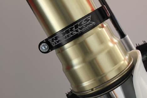
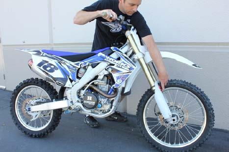
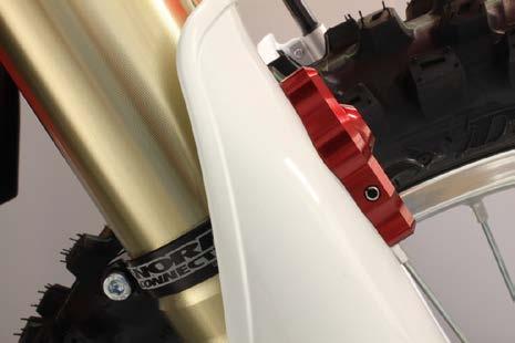
1 Product Drive Cameron Park, CA PH: VIEW INSTALLATION VIDEO AT PRO LAUNCH INSTALLATION INSTRUCTIONS We at Works Connection Inc. appreciate your purchase of the Pro Launch for your motorcycle. If you have any problems or questions, please contact us at Whenever you see symbols, heed their instructions! Always follow safe operating and maintenance practices. indicates a hazardous situation which, if not avoided, could result in death or serious injury. ICE indicates a hazardous situation which, if not avoided, could result in minor or moderate injury. Installing these parts improperly can cause a crash, serious injury or death. Before you start: Read these instructions and those in the OEM Service Manual for removing and installing fork tubes, as applicable. If you are not sure that you can follow the instructions, have these installed by a professional mechanic. Refer to the OEM Service Manual for proper torque values. Keep all of your OEM parts, as some parts they will be utilized in conjunction with the installation of your Pro Launch. The Pro Launch kit is designed for use with your OEM plastic fork guards. TOOLS & SUPPLIES REQUIRED: (not supplied) Torque wrench Common Hand Tools-(including X-Atco knife, Dremel tool, scissors, 3/16 drill, 5/16 drill, 4mm Allen wrench, Phillips screw driver) Hand Drill Loctite#242 (Blue) Before you begin working, be sure you are wearing eye protection and gloves. INSTALLATION AND ASSEMBLY OF PRO LAUNCH Do not attempt to install fork ring without first removing right side fork tube from bike. 1. Remove the front wheel and the right-side fork assembly in accordance with Service Manual. Remove Allen bolt from fork ring and slide the fork ring down fork tube. See Figure 1. On some applications you will have to slightly spread fork ring to get it past the widest spot (lower triple clamp area) on the fork tube. Once you have the fork ring in position as shown in Figure 1, start the Allen bolt but leave loose for now. NOTE-If applicable trim fork graphics so fork ring captures fork directly. 1
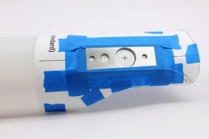
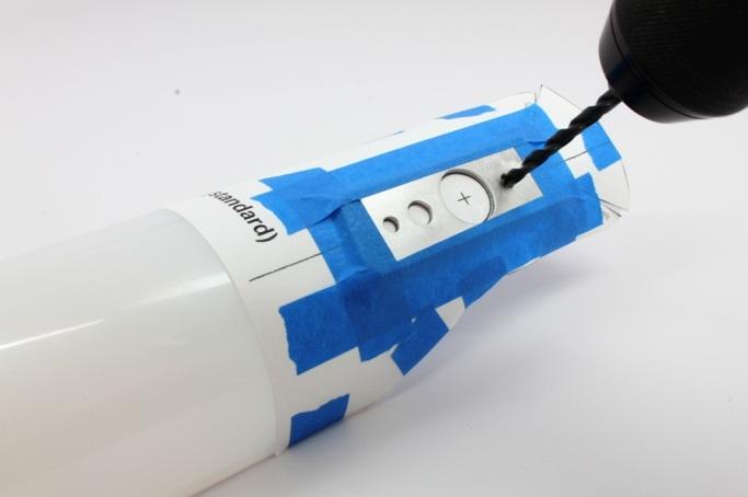
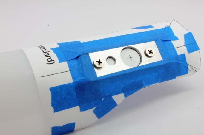
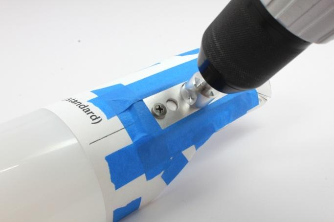
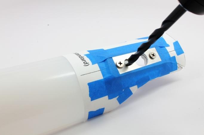
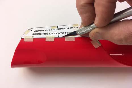
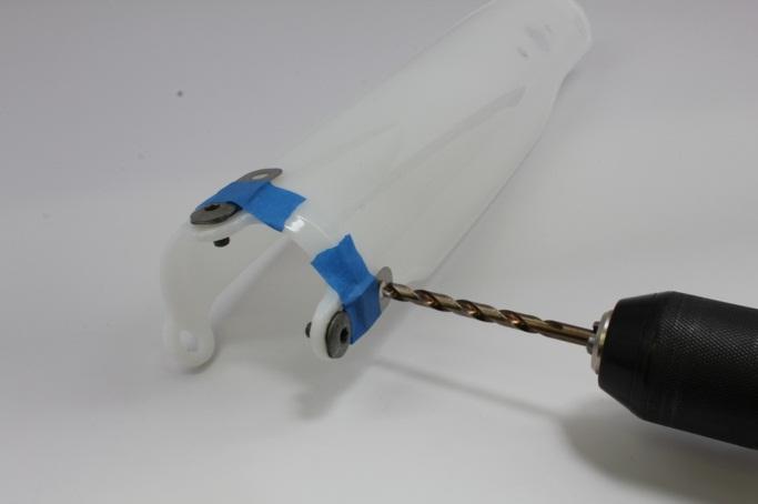
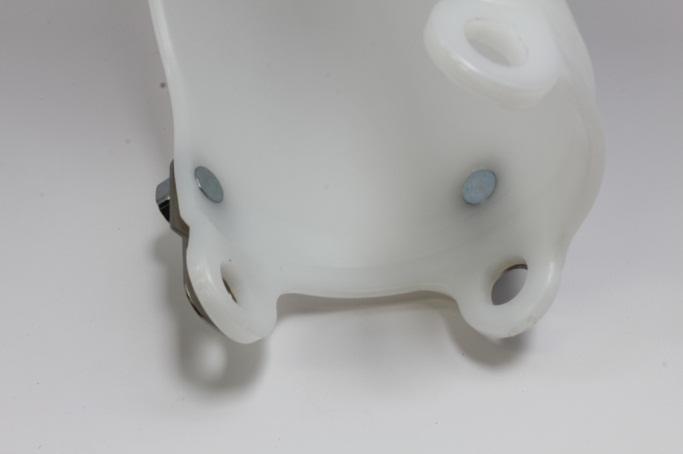
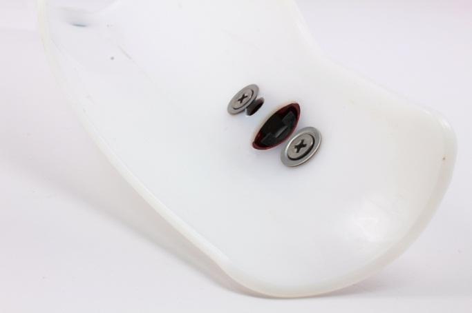
2 2. Determining the correct preload position. You have 3 options: a. 90mm-Taller riders/loose dirt conditions. b. 100mm-Best all-around choice. c. 110mm-Shorter riders/tacky conditions. Cut out the paper fork guard template (cut relief darts if indicated) with scissors. Remove the right-side fork guard from the fork assembly and tape the template to the fork guard making sure that the profile of the template fits the fork guard accurately. Use a minimum of six 1 pieces of ¾ masking tape to secure the template and prevent it from moving. This is very critical to assure the correct alignment for placement of the trigger mechanism later on in the installation process. See Figure Take the aluminum drill guide supplied in the kit and match it to the drawing of its outline on the paper template. Secure the drill guide to the paper template with masking tape. Note: Tape the entire perimeter of the drill guide. See Figure Using your 3/16 drill bit: pass it through the drill guide and drill through the fork guard for both 3/16 holes. See Figure 4 5. Push the two Phillips head trigger mechanism mount screws through the drill guide and into the fork guard. The screws will act as aligning dowels for the next two steps. See Figure Use the 3/4 countersink to bore the center hole in the fork guard. The drill guide will help maintain accuracy as the countersink bores through the fork guard. NOTE: The 3/4 hole is the primary support for the trigger mechanism. See Figure Drill the 5/16 hole. Remove the drill guide and paper template. Clean up any flashing after you re done. See Figure Cut out the trimming template and tape it to the wrap around portion of the fork guard. Use an X-Acto knife to score the trimming line into the fork guard. Remove the trimming template. Use the Dremel tool to trim/shape the fork guard to match the scored trimming line on the fork guard. See Figure 8. This step should be done by hand only. DO NOT USE POWER TOOLS OR DRILLS IN THIS NEXT STEP 9. Use the countersink to bevel the two trigger mechanism mount holes on the inside (backside) of the fork guard. See Figure 9. NOTE: The plastic cuts quickly and the use of a power drill could easily cut too large a hole or even bore through the fork guard making it useless. You will want to countersink the plastic enough so the backing washers fit down into the countersunk recesses. You may have to lean the countersink towards the top and bottom of the fork guard and carve out plastic in order to get a round (not oblong) countersunk area. 10. The two supplied fork guard supports help prevent excessive deflection of the fork guard while the Pro Launch is engaged. Use two fork guard bolts and masking tape to temporarily hold the supports in place while using the supports as templates. Drill two-¼ holes (for the 6mm studs) thru the fork guard, and then secure the supports to the fork guard using the supplied studs/lock washers/nuts. See Figures 10 and 10a. The supports go on the front/outside of the fork guard. The studs must be inserted from the backside of the fork guard, with the lock washers and nuts on the outside of the fork guard (Review photo 10a). SEVERE damage to the fork tube could occur if nuts are installed on the backside or inside the fork guard. Tighten both nuts until they are near flush with the end of the studs. Do not over-tighten. The 6mm studs should be near flush with the inside of the fork guard after the nuts are tight. 11. NOTE-If you have graphics on your fork guard: Trim away graphic material from the 3/4" hole. Hold trigger mechanism on fork guard and trace outline of trigger mechanism with a pencil. Trim and remove graphic material so trigger mechanism sits directly on fork guard. Install the trigger mechanism onto the fork guard using the backing washers and Phillips head screws. Use #242 Loctite on both screws. Make sure that you have a good fitting Phillips screwdriver, so as to ensure the screws fully seat the backing washers into their countersunk recesses. See Figure 11. 2
3 REASSEMBLY ORDER 1. Reinstall fork assembly in accordance with Service Manual. Ensure all fasteners are properly torqued. TORQUE: See OEM Service Manual for torque specification. 2. Install the fork guard with your Pro Launch. 3. Reinstall your front wheel in accordance with Service Manual. Ensure all fasteners are properly torqued. TORQUE: See OEM Service Manual for torque specification 4. The final step is to properly align the fork ring and trigger mechanism. This can be easily accomplished by putting your bike in the back of a truck or trailer so you can pull the front end down with tie-downs. Pull down just far enough so the trigger mechanism is just above the fork ring. Sight down from the top of the fork tube and adjust the fork ring so that it is in vertical alignment with the trigger mechanism. Torque the Allen bolt to secure fork ring. See Figure 12. TORQUE: 6 ft. lb. maximum. We have found that the easiest way to set the Pro Launch by yourself is to stand on the left side (shifter side) of the bike and perform the following: Place your left hand on the trigger. Next, roll the bike forward and quickly apply the front brake which will cause the forks to dive down and the fork ring to travel below the trigger assembly. Finally, time it so that you pull up on the trigger once the fork ring has traveled below the trigger assembly and you re all set. The trigger will release itself from the fork ring automatically when the front brake is applied and/or the front-end dives. Periodically check the mechanism for smooth operation and alignment with the fork ring. See Figure 13. Congratulations. You have now completed the installation of your Pro Launch for your motorcycle. After your first ride: Inspect your Pro Launch, front fork and fork guard. Check the torque on all the fasteners of your steering system. Regular checks and maintenance: Periodically check all the nuts and bolts to ensure that they are properly fastened and torqued, especially after adjustments. General Maintenance intervals are specified in your OEM Service Manual. If adjustment is needed, follow the guidelines in your OEM Service Manual. In the event of a crash: 1. Remove and inspect the Pro Launch. Look for damage, deformation or looseness. 2. Inspect your forks for any sign of damage or damaged parts. Operating the motorcycle with damaged parts can cause a crash, serious injury or death. If you aren t sure whether your Pro Launch is damaged, return it to Works Connection for inspection and evaluation. AFTER EVERY RIDE-Flush the inside of the fork guard/trigger mechanism to clear any debris. Periodic cleaning the trigger mechanism recommended- Remove the fork guard and the trigger assembly. Disassemble the trigger mechanism by carefully driving out the roll pin securing the trigger itself. Remove any debris from the trigger and the trigger body. Reinstall the roll pin. Install the trigger assembly on fork guard and fork guard back on bike. 3

4

5 a
6 6
7 7
PRO LAUNCH INSTALLATION INSTRUCTIONS
 12-339 4130 PRODUCT DRIVE, CAMERON PARK, CA 95682 PH: 1.530.642.9488 VIEW INSTALLATION VIDEO AT www.worksconnection.com/prolaunch/ 12-339 PRO LAUNCH INSTALLATION INSTRUCTIONS We at Works Connection Inc.
PERFORMANCE HOOD VENTS CONTENTS: Left Side Hood Vent (1) Right Side Hood Vent (1) Mounting Bracket, Inner (2) Mounting Bracket, Outer (2) OE Hood Temp
 Right Side Hood Vent (1) Mounting Bracket, Inner (2) Mounting Bracket, Outer (2) OE Hood Temp") CONTENTS: Left Side Hood Vent (1) Right Side Hood Vent (1) Mounting Bracket, Inner (2) Mounting Bracket, Outer (2) OE Hood Template (1) HARDWARE: Mounting Bracket, Inner X 2 Phillips Screw X 8 Mounting
CONTENTS: Left Side Hood Vent (1) Right Side Hood Vent (1) Mounting Bracket, Inner (2) Mounting Bracket, Outer (2) OE Hood Template (1) HARDWARE: Mounting Bracket, Inner X 2 Phillips Screw X 8 Mounting
Required tools General hand tools 21/64" drill bit Torque wrench Threadlocker Center punch
 Slipper Spring Kit (part numbers 2560, 2570 and 2580) Item Qty Part number Description 1... 8... 350054-50...3/8-16 x 1" grade 8 self-tapping screw 2... 4... 350084-00...7/16-14 x 4" grade 5 3... 6...
INSTALLATION INSTRUCTIONS HIDDEN WINCH MOUNTING KIT No for Chevrolet & GMC Trucks (for Warn Winches M6000, M8000, XD9000 & HS9500 only)
") INSTALLATION INSTRUCTIONS HIDDEN WINCH MOUNTING KIT No. 61770 for Chevrolet & GMC Trucks (for Warn Winches M6000, M8000, XD9000 & HS9500 only) Warn Light Bar 61090 and many other grille guards can be mounted
INSTALLATION INSTRUCTIONS HIDDEN WINCH MOUNTING KIT No. 61770 for Chevrolet & GMC Trucks (for Warn Winches M6000, M8000, XD9000 & HS9500 only) Warn Light Bar 61090 and many other grille guards can be mounted
Comfort Ride Shock absorber system part numbers 2450, 2460 and 2470 Installation Instructions
 Comfort Ride Shock absorber system part numbers 2450, 2460 and 2470 Installation Instructions All specifications are subject to change without notice. Item Qty Part number Description 1... 4... 204000-00...shock
WARNING indicates a potentially hazardous situation which, if not avoided, could result in property damage, serious personal injury or even death.
 Comfort Ride Third axle slipper leaf spring system (part numbers 2560-50, 2570-50 and 2580-50) and shock absorber system (part numbers 2450-50, 2460-50 and 2470-50) Installation Instructions All specifications
VRSC-DX Truck-Lite LED Headlight Installation Instructions
 VRSC-DX Truck-Lite LED Headlight Installation Instructions The following Instructions are for installing a 7 Truck-Lite LED headlight into a Harley Davidson VRSC-DX Night Rod Special fairing. Other 7 headlights
INSTALLATION AND OWNER S MANUAL Side Illumination Lights Z5150 for use with K 1200 LT
 INSTALLATION AND OWNER S MANUAL Side Illumination Lights Z5150 for use with K 1200 LT Read these instructions carefully and thoroughly before beginning work. Before installing the accessory, carefully
INSTALLATION INSTRUCTIONS
 DOUBLE X-WING BUTTON FRONT HOLESHOT HOOKUP INSTRUCTIONS Page You may view and/or print these instructions in color by.pdf format at ww.tamermotocross.com under the support tab, then scroll down to instructions.
Lexus NX Fine Mesh and Dynamic Radar Cruise Control Fine Mesh Grilles
 IMPORTANT: PLEASE KEEP THIS INSTRUCTION MANUAL FOR FUTURE REFERENCE! 2015-16 Lexus NX Fine Mesh and Dynamic Radar Cruise Control Fine Mesh Grilles Upper Insert - factory chrome surround and emblem reused
Comfort Ride Shock absorber system part numbers 2450, 2460 and 2470 Installation Instructions
 Comfort Ride Shock absorber system part numbers 2450, 2460 and 2470 Installation Instructions All specifications are subject to change without notice. MOUNTING FLANGE CENTER HOLE FRONT OF Item Qty Part
PART NUMBER: H630SSJ000. Kit Contents: A. Amplifier with Bracket (1) D. Badge (2) with push nuts (4)
 D. Badge (2) with push nuts (4)") Kit Contents: A. Amplifier with Bracket (1) D. Badge (2) with push nuts (4) E. Clip B. Harness (1) C. Cable tie (8) F. Mounting Hardware (2) G. Replacement Speaker (2) H. HVAC Duct extension (2) IMPORTANT:
Kit Contents: A. Amplifier with Bracket (1) D. Badge (2) with push nuts (4) E. Clip B. Harness (1) C. Cable tie (8) F. Mounting Hardware (2) G. Replacement Speaker (2) H. HVAC Duct extension (2) IMPORTANT:
Jeep Wrangler Heavy Duty Drag Link Installation Instructions
 THE INFORMATION CONTAINED IN THIS DRAWING IS THE SOLE PROPERTY OF SYNERGY MFG. ANY REPRODUCTION IN PART OR WHOLE WITHOUT THE WRITTEN PERMISSION OF SYNERGY MFG IS PROHIBITED. Revisions Rev. Description
Installation Instructions Z-Gate Shifter
 Installation Instructions Z-Gate Shifter Part Number 80681 1998, 2001 by B&M Racing and Performance Products The B&M Z-Gate shifter can be used in vehicles equipped with most popular three speed automatic
INSTALLATION INSTRUCTIONS
 INSTALLATION INSTRUCTIONS [1] Description: Tow Hitch Wire Harness Kit [2] Application: Nissan Rogue Note: Tow Harness application is limited to specific vehicle option packages that include tow harness
SPECIAL INSTALLATION INSTRUCTIONS
 SPECIAL INSTALLATION INSTRUCTIONS WARN 4X FLARES FRONT AND REAR '98 TOYOTA HILUX DUAL-CAB As you read these instructions, you will see NOTES, CAUTIONS and WARNINGS. Each message has a specific purpose.
GT Mustang Shaker
 CD4II3CU CDC Mustang 5.0 Shaker 2011-2014 2011-2014 5.0 GT Mustang Shaker Part #1111-7000-01 Component Check List: Shaker Assembly: Part # 1 - Aluminum Shaker Scoop 183020 1 Upper Air Box 1111-3301-01
WARNING. BX Suzuki Grand Vitara Installation Instructions. Bolt Torque Specifications. Bolt Torque Specifications
 Attachment Tab Height: 21-1/2 Attachment Tab Width: 24 Please read BOTH these and the General Instructions prior to installing or operating this equipment. 1. Blue Ox towing products and accessories are
INSTALLATION GUIDE. Doc ID: A Doc Rev:
 REKLUSE MOTOR SPORTS EXP Kit for Harley-Davidson Big Twin Hydraulic-Actuated OVERVIEW INSTALLATION GUIDE Doc ID: 191-6200A Doc Rev: 061215 This kit replaces the OEM clutch pack (friction disks and drive
INSTALLATION INSTRUCTIONS FOR THE MOTOR TRIKE GL1500 RAKE KIT
 INSTALLATION INSTRUCTIONS FOR THE MOTOR TRIKE GL1500 RAKE KIT Thank you for choosing the Motor Trike GL1500 Rake Kit. We ask that you read the directions before you start and follow them very closely.
Mustang Shaker
 2005-2009 Mustang Shaker CDC #110050 ( 05/ 06) or 0711-7000-01 ( 07/ 09) Component Check List: Quantity/Description Part # CDC Installer 1 - Engine Cover Assembly 114050 1 - Aluminum Shaker Scoop 183020
Tusk Pannier Racks. Instructions and information KLR
 1 Tusk Pannier Racks Instructions and information KLR650 2008 + Congratulations on your purchase of the Tusk Pannier Racks. These racks are made to handle extreme adventure riding, but work great for the
Established in 1977 KJ71050BK JK Hood Cowl
 Established in 1977 KJ71050BK JK Hood Cowl!!COWL AND SIDE SCOOPS MUST BE PAINTED TO PREVENT UV DAMAGE!! Like Us Share Us Watch Us Follow Us www.daystarweb.com Tech Support Contact Info Tech@DaystarWeb.com
Lexus ES Fine Mesh and Adaptive Cruise Control Fine Mesh Grilles Upper and Lower Replacements
 IMPORTANT: PLEASE KEEP THIS INSTRUCTION MANUAL FOR FUTURE REFERENCE! 2013-15 Lexus ES Fine Mesh and Adaptive Cruise Control Fine Mesh Grilles Upper and Lower Replacements Part #1372-0102-13 / Black Ice
Fitting instructions for Lynx R Fairing - KTM 690
 Fitting instructions for Lynx R Fairing - KTM 690 Thank you for purchasing the Lynx R fairing. Your fairing kit comes largely completed, with most of the fitting time involved with the attachment of your
2010 Mustang V6 Shaker CDC #
 - - Incomplete 2010 Mustang V6 Shaker CDC # 1011-7002-01 Component Check List: Quantity/Description Part # Engine Cover Assembly 1011-6000-01 1 Engine Cover w/ Upper Air Tube 0511-2100-01 1 Aluminum Shaker
1.1 Quad Valve and Tri-Valve. Contents WATER DUMP BODY O-RING EXHAUST VALVE QUAD VALVE TIE WRAP EXHAUST MAIN BODY O-RING
 Quad Valve and Tri-Valve Exhaust Assembly on Fiberglass Helmets Quad Valve and Tri-Valve Exhaust Contents QUAD-1 QUAD-2 QUAD-2 QUAD-2 QUAD-6 QUAD-7 1.1 Quad Valve and Tri- Valve Exhaust Assembly on Fiberglass
Part # GM A Body CoilOver System
 350 S. St. Charles St. Jasper, In. 47546 Ph. 812.482.2932 Fax 812.634.6632 www.ridetech.com Part # 11240210 68-72 GM A Body CoilOver System Front Components: 1 11243510 Front Single-adjustable CoilOvers
99-03 V6 "Shaker" System Instructions. *03 Model requires new hood Contents w/ Kit. Tool List For Appliqué:
 99-03 V6 "Shaker" System Instructions *03 Model requires new hood Contents w/ Kit 1 - Hood Appliqué 1 - Aluminum Shaker Scoop 1 - Lower Air Box w/drain tube fittings (2) 1 - Upper Air Box w/cdc nameplate
 INSTALLATION INSTRUCTIONS Accessory ACCESSORY HANDSFREELINK (WITH MOON) Application 2009 PILOT Publications No. AII 39492 Issue Date MAY 2008 PARTS LIST HFL Attachment Kit 2 Washer screws, 4 x 12 mm HFL
Installation Instructions QUICKSILVER CONSOLE SHIFTER Fits: Chevelle / El Camino
 WORK SAFELY! For maximum safety, perform this installation on a clean, level surface and with the engine turned off. Place blocks or wedges in front of and behind both rear wheels to prevent movement in
INSTALLATION INSTRUCTIONS
 INSTALLATION INSTRUCTIONS Accessory HITCH Application 2009 CR-V Publications No. AII 40373 Issue Date AUG 2008 PARTS LIST Plain washer, 12 mm Trailer Hitch Kit P/N 08L92-SWA-100 Trailer hitch 6 Spring
GENUINE REAR SPOILER
 GENUINE REAR SPOILER IMPORTANT POINTS IN PAINTING PART NAME: REAR SPOILER PART NUMBER: 0000-8Y-H50/GHK1 V4 920/G44B V4 920 VEHICLE: MAZDA6 1 PAINT AREAS SURFACE TREATMENT a : Paint same as body color b
GL1800 TRAILER HITCH - INSTALLATION INSTRUCTIONS #GL
 GL1800 TRAILER HITCH - INSTALLATION INSTRUCTIONS #GL18007-20 Read through these instructions completely before attempting installation, lay out all pieces including the numbered hardware bags to familiarize
INSTALLATION INSTRUCTIONS
 INSTALLATION INSTRUCTIONS Accessory Application Publications No. BII 37518 2008 RDX Issue Date JUL 2007 PARTS LIST 10 Plain washers, 12 mm Trailer Hitch Kit P/N 08L92-STK-200 Trailer hitch 6 Lock washers,
Technical Support (707)
") Installation Instructions CONSOLE MEGASHIFTER Fits: 1982-1992 Camaro & Firebird w/automatic Transmission *except 1988-1992 Firebird Formula Model Catalog # 80692 WORK SAFELY! For maximum safety, perform
Installation Instructions CONSOLE MEGASHIFTER Fits: 1982-1992 Camaro & Firebird w/automatic Transmission *except 1988-1992 Firebird Formula Model Catalog # 80692 WORK SAFELY! For maximum safety, perform
INSTALLATION INSTRUCTIONS
 INSTALLATION INSTRUCTIONS Accessory Application Publications No. AII 40454 XM SATELLITE RADIO 2009 S2000 Issue Date AUG 2008 PARTS LIST Template XM Radio Unit Kit (sold separately): P/N 08A53-S2A-101 XM
2015+ Mustang Rear Valance Installation Instructions P/N: (R F953) (R F953BS)
 (R F953BS)") 2015+ Mustang Rear Valance Installation Instructions P/N: 421894 (R1315-17F953) 421919 (R1315-17F953BS) 39555 Schoolcraft Rd, Plymouth MI, 48170 800.59.ROUSH 2015+ Mustang Rear Valance Kit Installation
2015+ Mustang Rear Valance Installation Instructions P/N: 421894 (R1315-17F953) 421919 (R1315-17F953BS) 39555 Schoolcraft Rd, Plymouth MI, 48170 800.59.ROUSH 2015+ Mustang Rear Valance Kit Installation
INSTALLATION INSTRUCTIONS
 INSTALLATION INSTRUCTIONS Document# 19-0038 2004+ Lotus Elise (Series 2) Rear Clamshell Removal Kit Safely support the vehicle. This is a two-person job. Allow 1 to 2 hours for initial disassembly. Have
Slave Cylinder Weep Hole Drilling Procedure
 Slave Cylinder Weep Hole Drilling Procedure Tools Required: T20 Torx Driver T25 Torx Driver T25 Torx Bit with ¼ Ratchet Wrench 4mm Hex Key (Allen wrench) 5mm Hex Key 6mm Hex Key 8mm Hex Key 12mm Hex Key
SAFETY THIS PRODUCT IS FOR OFFROAD USE ONLY. ALL LIABILITY FOR INSTALLATION AND USE RESTS WITH THE OWNER.
 SAFETY Your safety and the safety of others is very important. In order to help you make informed decisions about safety, we have provided installation instructions and other information. These instructions
INSTALLATION & OWNER S MANUAL
 Rev. B, p. 1 of 25 INSTALLATION & OWNER S MANUAL POLARIS RANGER RCS (for models XP or HD) (for model years 2009-) cab without doors kit (p/n 1POLRCWD) cab with doors kit (p/n 1POLRC) doors only kit (p/n
Z-Gate Universal Shifter
 Installation Instructions Z-Gate Universal Shifter Fits: GM, Ford, Lincoln and Chrysler Transmissions See Application Guide for Specific Applications Part #80681 Rev 06/01/2018 WORK SAFELY! For maximum
Light Truck MegaShifter
 Installation Instructions Light Truck MegaShifter The B&M Light Truck Megashifter shifter is designed to be used in most light trucks equipped with most popular three speed or four speed automatic transmissions.
INSTALLATION AND OWNER S MANUAL Wing Deflectors, Fairing Mount N5107 and N5109 for HONDA GL1800
 INSTALLATION AND OWNER S MANUAL Wing Deflectors, Fairing Mount N5107 and N5109 for HONDA GL1800 Thank you for purchasing a National Cycle product. Please read these instructions carefully and thoroughly
Section 13. Tail Rotor Drive. RotorWay International A600 TALON Construction Manual. Section 13. Page A
 RotorWay International Page A Tail Rotor Drive Procedures covered in this section: Install driveshafts and gearboxes; install drive belt and tensioner; fabricate and install tail rotor pitch actuator arms;
TOYOTA HIGHLANDER RUNNING BOARD HIGHLANDER HV Preparation
 Preparation Part Number: PT738-48080 Kit Contents Item # Quantity Reqd. Description 1 1 Driver Side Running Board 2 1 Passenger Side Running Board 3 4 /Middle Mount Bracket 4 2 Rear Mount Bracket 5 2 Rear
INSTALLATION INSTRUCTIONS
 INSTALLATION INSTRUCTIONS Accessory Application Publications No. CD CHANGER ATTACHMENT KIT 2005 CIVIC SI AII 27936 Issue Date AUG 2004 PARTS LIST CD Changer Attachment Kit (sold separately): P/N 08B26-S5T-100
INSTALLATION INSTRUCTIONS
 INSTALLATION INSTRUCTIONS Part # 751-FP2500 IMPORTANT INFORMATION This Jagg oil cooler must be installed following these instructions. Read the easy-to-follow instructions fully prior to starting the installation
M52tu-M54 VANOS Assembly & Timing Using G.A.S. Professional Cam Tool Kit
 Home BMW Solutions Porsche Solutions DIY Tech Engine Services Dyno Services Machining About Contact Store Tool Rental M52tu-M54 VANOS Assembly & Timing Using G.A.S. Professional Cam Tool Kit This procedure
2011 Cadillac CTS Coupe EGX Exhaust Tip & Rear Valance Mesh Accent Kit Part #: Complete E
 BILLET GRILLS IMPORTANT: PLEASE KEEP THIS INSTRUCTION MANUAL FOR FUTURE REFERENCE! 2011 Cadillac CTS Coupe EGX Exhaust Tip & Rear Valance Mesh Accent Kit Part #: Complete 5122-1900-11E TOOLS REQUIRED Automotive
Shock Absorber Rebuild Manual
 Shock Absorber Rebuild Manual Model PODIUM RC3 FOX RACING SHOX 130 Hangar Way, Watsonville, CA 95076 PHONE 800.369.7469 FAX 831.768.7026 Email: psservicemw@ridefox.com Website: www.ridefox.com Disclaimer
Cylinder and Valve: AirHawk II Air Mask
 Cylinder and Valve: AirHawk II Air Mask MAINTENANCE AND REPAIR MSA 011 (L) Rev. 0 MSA 2010 Prnt. Spec. 10000005389(I) Mat. 10104218 Doc. 10104218 Parts List Cylinder Replacement Kits Item P/N Description
INSTALLATION INSTRUCTIONS
 INSTRUCTIONS Accessory Application Publications No. 2011 CIVIC AII 44380 S 2-DOOR Issue Date AUG 2010 NOTE: The side under spoilers cannot be installed on a vehicle equipped with splash guards. PARTS LIST
INSTALLATION INSTRUCTIONS
 INSTALLATION INSTRUCTIONS Accessory Application Publications No. AII 33373 ATTACHMENT KIT (TRUNK MOUNT) 2007 S2000 Issue Date AUG 2006 PARTS LIST Plain washer CD Changer Attachment Kit: P/N 08B26-S2A-100A
Installation Manual TWM Performance Short Shifter Cobalt SS/SC, SS/TC, HHR SS, Ion Redline and Saab 9-3
 Page 1 Installation Manual TWM Performance Short Shifter Cobalt SS/SC, SS/TC, HHR SS, Ion Redline and Saab 9-3 Please Note: It is preferable to park on a flat surface, as you will have to engage and disengage
Dear Customers. : i MiEV INSTRUMENT PANEL ILLUMINATION INSTALLATION AND HANDLING INSTRUCTIONS. Attention
 Dear Customers Thank you for purchasing a Mitsubishi genuine optional part. For proper use of the product, please read this leaflet thoroughly. It is recommended you keep this leaflet at hand for future
Mustang V6 Shaker 99-04* Components Check List:
 Mustang V6 Shaker 99-04* Components Check List: *03 Model requires new hood CDC Inspected Installer Check Quantity Descriptions 1- Hood Appliqué 1- Aluminum Shaker Scoop 1- Lower Air Box w/drain tube fittings
HID INSTALLATION ON RST1000 Futura
 HID INSTALLATION ON RST1000 Futura Disclaimer: This is a full description of what I have done to my motorcycle. I am in no way suggesting you do as I have done by following these instructions. I have not
INSTALLATION INSTRUCTIONS
 INSTALLATION INSTRUCTIONS Accessory Application Publications No. CD CHANGER ATTACHMENT KIT 2004 CR-V AII 26118 Issue Date SEP 2003 PARTS LIST CD Changer Attachment Kit (sold separately): P/N 08B26-S9A-100
WARNING. BX Saturn Vue and Redline Chevy Captiva (All Models) Installation Instructions
 Installation Instructions") Attachment Tab Height: 21-1/2 Attachment Tab Width: 18-1/2 Please read BOTH these and the General Information sheet prior to installing or operating this equipment. 1. Blue Ox towing products and accessories
Attachment Tab Height: 21-1/2 Attachment Tab Width: 18-1/2 Please read BOTH these and the General Information sheet prior to installing or operating this equipment. 1. Blue Ox towing products and accessories
Installation Instructions
 Parts Installation Instructions DESCRIPTION PART # QTY A Alignment Tab PN ESB101 1 B Drill Guide PN ESB102 1 C Actuator Cable Assembly PN ESB103 1 C1 72 Actuator Cable 1 C2 5/16 Jam Nut 1 C3 Star Washer
A B C D E F. Tools Required (supplied by others)
") Page 1 of 17 Parts List Below Deck Automatic Retractable Security Cover Kit (1) Tube End Bearing Plate (A) (1) Rope Reel and Cover Drum Motor Assembly (B) (1) Cover Drum (1) Pulley Support Channel (2)
Page 1 of 17 Parts List Below Deck Automatic Retractable Security Cover Kit (1) Tube End Bearing Plate (A) (1) Rope Reel and Cover Drum Motor Assembly (B) (1) Cover Drum (1) Pulley Support Channel (2)
CHEVROLET TAHOE/DENALI/AVALANCHE/YUKON/ SILVERADO/SIERRA 2007+
 CHEVROLET TAHOE/DENALI/AVALANCHE/YUKON/ SILVERADO/SIERRA 2007+ INSTALLATION INTRODUCTION 1. REMOVING THE FENDER AND DOORS FROM THE A-PILLAR AND DISCONNECTING THE WIRE HARNESS @ THE DOOR JAM 2. REMOVING
TOYOTA VENZA 2009 TRAILER WIRE HARNESS Procedure
 Part Number: PT791-0T099 Kit Contents Item # Quantity Reqd. Description 1 1 Trailer Wire Harness Module 2 1 4-Flat Harness 3 1 Battery Power Wire Harness 4 1 Mounting Bracket, 4-Flat 5 2 Screw #10-24 6
DISASSEMBLY & REASSEMBLY INSTRUCTIONS
 DISASSEMBLY & REASSEMBLY INSTRUCTIONS FOR SINGLE ACTING TELESCOPIC CYLINDERS MUNCIE POWER PRODUCTS, INC. Telescopic Cylinder Disassembly & Reassembly Instructions TABLE OF CONTENTS Warning & Safety Recommendations...
INSTALLATION INSTRUCTIONS
 INSTALLATION INSTRUCTIONS Accessory Application Publications No. CIVIC All 30175-31616 2 AND 4-DOOR P/N 08E10-SNA-100 Issue Date DEC 2005 NOTE: The interior illumination lights cannot be installed on 2-door
INSTALLATION INSTRUCTIONS
 INSTALLATION INSTRUCTIONS Accessory Application Publications No. AII 26320 ATTACHMENT KIT 2004 S2000 Issue Date OCT 2003 PARTS LIST CD Changer Attachment Kit: P/N 08B26-S2A-100A Plain washer Template CD
Installing a genuine HoodLift on a Jeep JK with an AEV hood
 Installing a genuine HoodLift on a Jeep JK with an AEV hood (to print a full-color version of these instructions go to www.hoodlift.com/products.html. Scroll down to the JK HoodLift and click on the AEV
INSTALLATION INSTRUCTIONS
 INSTALLATION INSTRUCTIONS Accessory Application Publications No. AII 44415 2011 CIVIC 4-DOOR Issue Date AUG 2010 PARTS LIST Trunk spoiler 2 Cap nuts 2 Screws Left trunk spring (marked yellow) Right trunk
 INSTALLATION INSTRUCTIONS Accessory Application Publications No. 2010 CIVIC All 42479 2- AND 4-DOOR P/N 08E10-SNA-110 Issue Date AUG 2009 NOTE: The interior illumination lights cannot be installed on 2-door
GENUINE PARTS INSTALLATION INSTRUCTIONS
 GENUINE PARTS INSTALLATION INSTRUCTIONS DESCRIPTION: APPLICATION: PART NUMBER: KIT-CARBON FIBER REAR SPOILER INFINITI Q50 T99J1 J5000 KIT CONTENTS: Item A B C D Qty. 1 4 1 1 Part Description Spoiler Assembly
Installation Instructions Right Hand Drive Megashifter
 Installation Instructions Right Hand Drive Megashifter Part Number 80685 1995, 2001, 2006, 2010 by B&M Racing & Performance Products The B&M Right Hand Drive Megashifter is designed specifically for vehicles
INSTALLATION INSTRUCTIONS
 INSTALLATION INSTRUCTIONS Part # 751-FP2600 IMPORTANT INFORMATION This Jagg oil cooler must be installed following these instructions. Read the easy-to-follow instructions fully prior to starting the installation
»Product» Safety Warning
 D1401 Installation Instructions 2013 Ram 3500, 2014 Ram 2500 4.5" Radius Arm Suspension Lift Read and understand all instructions and warnings prior to installation of product and operation of vehicle.
TOYOTA PRIUS XM SATELLITE RADIO Preparation
 Preparation Part Number: Mounting Kit PT546-4700 Tuner Assy 8680-0W03 NOTE: Part number of this accessory may not be the same as the part number shown. Tuner Assembly Kit Contents (8680-0W03) Item # Quantity
INSTALLATION INSTRUCTIONS
 INSTALLATION INSTRUCTIONS Accessory Application 2012 CIVIC 4-DOOR Publications No. AII 45625-46263 Issue Date MAY 2011 PARTS LIST Trunk spoiler Left trunk spring (marked yellow) Template 4 Clip grommets
ROUSH Convertible Stylebar Installation Instructions P/N: (1315-STYLEBAR) Convertible Only
 Convertible Only") Installation Instructions P/N: 421911 (1315-STYLEBAR) Convertible Only 39555 Schoolcraft Rd, Plymouth MI, 48170 800.59.ROUSH Installation Instructions P/N: 421911 (1315-STYLEBAR) Convertible Only Application:
Installation Instructions P/N: 421911 (1315-STYLEBAR) Convertible Only 39555 Schoolcraft Rd, Plymouth MI, 48170 800.59.ROUSH Installation Instructions P/N: 421911 (1315-STYLEBAR) Convertible Only Application:
Conflicts: Vehicles with a sunroof
 Toyota 4Runner Non/MR 2010-10.2 Overhead Video Part Number: 00016-00110; Fit Kit -00110-15, Beige 00016-00120; Fit Kit -00120-15, Gray Accessory Code: ED6 Conflicts: Vehicles with a sunroof Kit Contents:
Hurst VMATIC3 INSTALLATION
 FORM 159 8530 07/12 Hurst VMATIC3 3-Speed & 4-Speed Automatic Shifter Catalog #3838530 2012 by Hurst Performance The Hurst Vmatic3 shifter can be used in vehicles equipped with most popular three speed
RAMPAGE POWER LIFT RAMP
 RAMPAGE POWER LIFT RAMP INSTALLATION AND OPERATING INSTRUCTIONS (3/10/07) The Rampage Power Lift Ramp is the fast, easy, and safe way to load a motorcycle into a truck. One person can load or unload a
Maintenance Information
 16572679 Edition 2 May 2014 Air Drill QP Series Maintenance Information Save These Instructions Product Safety Information WARNING Failure to observe the following warnings, and to avoid these potentially
INSTALLATION INSTRUCTIONS
 INSTALLATION INSTRUCTIONS Accessory Application Publications No. ATTACHMENT (EX-L WITH NAVI) 2008 RIDGELINE AII 36587 Issue Date MAY 2007 PARTS LIST Attachment Kit P/N: 08B21-SJC-102 Template Rear camera
California Pony Cars Full Length Radiator Cover (07-09 GT500)
") California Pony Cars Full Length Radiator Cover (07-09 GT500) Installation Time: 15-30 Minutes Required Tools: Flathead Screwdriver or Pick 10mm Wrench or Ratchet & 10mm Socket Optional Tools CSM Badge
California Pony Cars Full Length Radiator Cover (07-09 GT500) Installation Time: 15-30 Minutes Required Tools: Flathead Screwdriver or Pick 10mm Wrench or Ratchet & 10mm Socket Optional Tools CSM Badge
INSTALLATION INSTRUCTIONS INFINITI CELLPORT UNIVERSAL HANDS FREE SYSTEM
 INSTALLATION INSTRUCTIONS 1. DESCRIPTION: INFINITI CELLPORT UNIVERSAL HANDS FREE SYSTEM 2. APPLICATION: 2002 Q45 3. PART NUMBER: 948T3CELLR95 (VPC) or 999Q2TN000 (PDC) 4. TOOLS REQUIRED: a. Loctite 242
P4 CHAINSTAY INTEGRATED ROCKER BRAKE (CSIRB) INSTALLATION
 INSTALLATION") P4 CHAINSTAY INTEGRATED ROCKER BRAKE (CSIRB) INSTALLATION TOOLS REQUIRED 2, 2.5, 3, 5 mm allen keys 8, 9 mm open faced cone wrench Pliers Cable cutters Torque wrench MATERIALS REQUIRED: 1 x P4 chainstay
P4 CHAINSTAY INTEGRATED ROCKER BRAKE (CSIRB) INSTALLATION TOOLS REQUIRED 2, 2.5, 3, 5 mm allen keys 8, 9 mm open faced cone wrench Pliers Cable cutters Torque wrench MATERIALS REQUIRED: 1 x P4 chainstay
Installation Instructions Console Megashifter
 Installation Instructions Console Megashifter 1968-1969 Camaro Part Number 81035 This B&M Megashifter is designed to fit in the console of a 1968-1969 Chevrolet Camaro. In 1968, these vehicles were equipped
Owner s Manual And Guide To Installation
 Owner s Manual And Guide To Installation < # > TABLE OF CONTENTS 1 How to Use...3 1.1 Control Keypad...3 1.2 Mounting Hardware...4 1.3 Auto Launch Details...5 1.4 Trailering with the SWITCHBLADE...6 1.5
ST 93 RIPPER INSTALL KIT
 ST 93 RIPPER INSTALL KIT P/N 2883777;2883778;2883779 APPLICATION The Timbersled Ripper ST93 Install Kit is designed to fit all Timbersled ST90 and ST93 Ripper models. This includes; Timbersled Model No.
WARNING. BX Fiat 500L Trekking/Easy/Pop/Lounge Installation Instructions
 2014-16 Fiat 500L Trekking/Easy/Pop/Lounge Attachment Tab Height: 15 Attachment Tab Width: 23 Please read BOTH these and the General Information sheet prior to installing or operating this equipment. 1.
SAFETY. Read and understand all safety precautions and instructions before installing this product.
 SAFETY Installation Instructions Application: 2015+ FORD F150 Your safety and the safety of others is very important. In order to help you make informed decisions about safety, we have provided installation
INSTALLATION INSTRUCTIONS
 INSTALLATION INSTRUCTIONS Accessory Application Publications No. AII 25877 PILOT Issue Date AUG 2003 Optional ATF and power steering coolers are required when installing the trailer hitch. 2 Spacers PARTS
Wildcat System Instructions
 Wildcat System Instructions NOTE: Most steps contained in these instructions will need to be repeated on the other side of the vehicle. Prior to assembly of windshield it is necessary to establish what
'99-03 CHEVROLET/GMC IFS 4WD 6" SUSPENSION SYSTEM P/N INSTALLATION INSTRUCTIONS
 1/16/04 '99-03 CHEVROLET/GMC IFS 4WD 6" SUSPENSION SYSTEM P/N. 10-41099 INSTALLATION INSTRUCTIONS NOTE: Each Lift Kit and options to Lift Kits are packaged separately. Therefore, installation procedures
LAGUNA SERIES SLIDING DOOR KITS
 INSTALLATION INSTRUCTIONS LAGUNA SERIES SLIDING DOOR KITS 503 E. Vernon Avenue, Los Angeles, CA 90058-86 (800) 4-644 Fax (800) 6-399 crlaurence.com M054_REV_A ORDER OF ASSEMBLY AND INSTALLATION PARTS LIST...
HYDRAULIC PUMP. INSTALLATION, OPERATION, & MAINTENANCE MANUAL MAINTENANCE MANUAL #: MM-HP Rev. A Page 1 of 12
 INSTALLATION, OPERATION, & #: MM-HP001 4-20-09 Rev. A Page 1 of 12 HYDRAULIC PUMP PART NUMBER HP46982ALSL & HP46982SL HYDRAULIC PUMP MM-HP001 Rev. A Page 2 of 12 Table of Contents 1.0 General Page 3 2.0
TOYOTA VENZA 2009 TRAILER WIRE HARNESS Procedure
 Part Number: PT791-0T099 Kit Contents Item # Quantity Reqd. Description 1 1 Trailer Wire Harness Module 2 1 4-Flat Harness 3 1 Battery Power Wire Harness 4 1 Mounting Bracket, 4-Flat 5 2 Screw #10-24 6
pg 2 Disassembly, Wire and Amplifier Plate Installation pg 9 Glovebox Subwoofer Installation pg 13 Kick Panel Speakers Installation
 RZ3-5KRC RZR XP1000 & 2015+ RZR900 with Ride Command SSV Works 5 Speaker Audio Kit pg 2 Disassembly, Wire and Amplifier Plate Installation pg 9 Glovebox Subwoofer Installation pg 13 Kick Panel Speakers
Ford Super Duty Recoil Traction Bar System. Part#: ,123409
 Part#: 123418,123409 Ford Super Duty Recoil Traction Bar System Rev. 011017 491 W. Garfield Ave., Coldwater, MI 49036. Phone: 517-279-2135 Web/live chat: www.bds-suspension.com. E-mail: tech-bds@sporttruckusainc.com
SAFETY THIS PRODUCT IS FOR OFFROAD USE ONLY. ALL LIABILITY FOR INSTALLATION AND USE RESTS WITH THE OWNER.
 SAFETY Your safety and the safety of others is very important. In order to help you make informed decisions about safety, we have provided installation instructions and other information. These instructions