HIGH VOLTAGE LABORATORY INSTYTUT ENERGETYKI
|
|
|
- Maximilian Cole
- 6 years ago
- Views:
Transcription

1 HIGH VOLTAGE LABORATORY INSTYTUT ENERGETYKI POLAND WARSZAWA, ul. Mory 8, tel. (+48 22) , fax (+48 22) EWN/70/E/11-1 APPENDIX 3 APPENDIX 3 for test report EWN/70/E/11-1 Report of performed tests in Distribution Equipment Laboratory of Institute of Power Engineering in Warsaw. Test Report No. EUR/33/E/11-1E of Test Report No. EUR/33/E/11-2E of (Short-time current tests, short-circuit withstand capability test and mechanical.)
2
3 EUR/33/E/11-2E Page 2/16 Contents Page 1. Test object Description Technical data Technical documentation Preparation for tests 3 2. Scope of tests 3 3. Test and measuring circuits 4 4. Tests and theirs detailed results 7 5. Test results evaluation 8 Annexes: 1. Short-circuit test records 2. Photographs taken during the tests 3. Documentations delivered by orderer Report contents: numbered pages 16 records (pages not numbered) 5 tables 3 figures 3 photographs 10
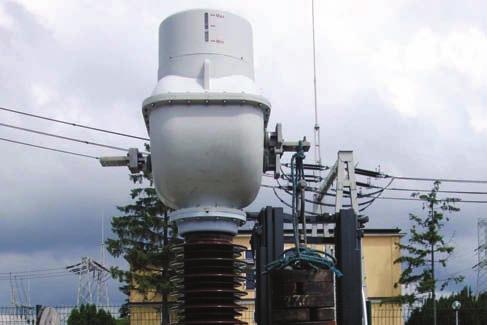
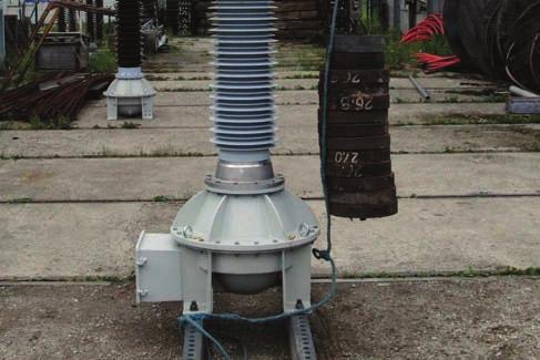
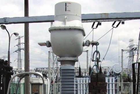
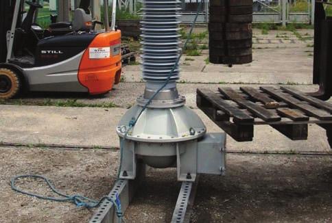
4 EUR/33/E/11-2E Page 3/16 1. TEST OBJECT 1.1 Description Combined transformer type PVA 123 is used for supplying of measuring and protection circuits in the network of nominal voltage 110 kv and frequency 50 Hz. The transformer consists of current and voltage transformers mounted in common porcelain enclosure immersed with transformer oil. 1.2 Technical data The Manufacturer attributed the following construction data to the test object. Rated voltage Rated frequency Rated continuous thermal current Rated short-time current Rated dynamic current Rated static load 110/ 3 kv 50 Hz 50 A, 100 A, 200 A 10 ka, 20 ka, 40 ka 25 ka, 50 ka, 100 ka 3600 N 1.3 Technical documentation For the purpose of tests the orderer delivered the following technical documentation: - dimension drawing of combined transformer PVA 123, No.2GKK , ABB Sp. z o.o., (Annex 3), - electrical diagram of combined transformer PVA 123, ABB Sp. z o.o., (Annex 3). The laboratory proceeded the identification of test object on the base of above documentation and the nameplate. 1.4 Preparation for tests The test object was prepared for test by factory. 2. SCOPE OF TESTS Test program, agreed with orderer, comprised the following tests according to requirements of EN :2003 (idt IEC :2002): - short-time current tests of current transformer windings acc. to item 6.2 a) of above standards at the following parameters: for 50 A: I dyn 25 ka, I th = 10 ka t th = 1 s, I th 2 t th 100 ka 2 s, for 100 A: I dyn 50 ka, I th = 20 ka t th = 1 s, I th 2 t th 400 ka 2 s, for 200 A: I dyn 100 ka, I th = 40 ka t th = 1 s, I th 2 t th 1600 ka 2 s, - short-circuit withstand capability test of voltage transformer acc. to item 6.2 f) of above standards at parameters: U p 63,5 kv, t p = 1 s, - mechanical tests acc. to item 6.4 d) of above standards for F R = 3600 N and resulting dynamic load of terminals P1 and P2/A 200 A.
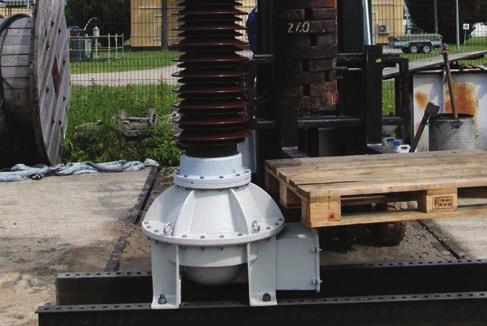
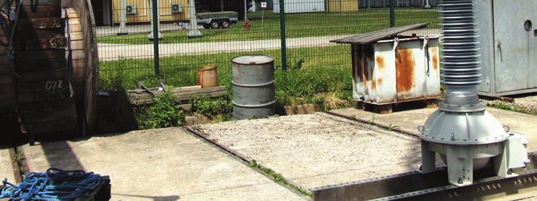
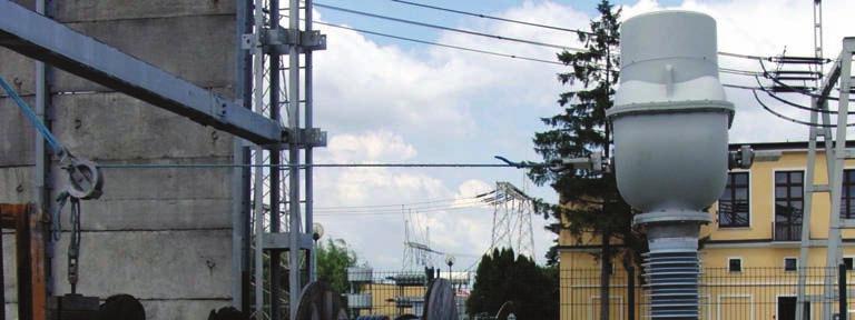
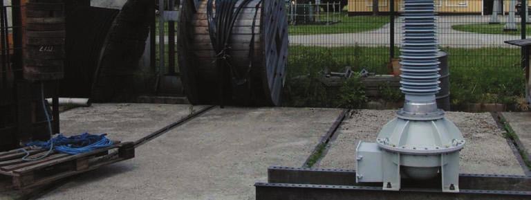
5 EUR/33/E/11-2E Page 4/16 3. TEST AND MEASURING CIRCUITS For the tests the transformer was fixed to the rigid construction of the test stand. Short-time current tests were made in one phase circuit presented on fig. 1 and 2. Short-circuit withstand capability tests were made in test circuit presented on fig. 3. Mechanical tests were performed applying the load consecutively to the transformer s terminals as shown on photographs 5 to 10 in Annex 2. The following quantities were recorded during the tests using digital recorder type HIOKI 8842: - primary current of current transformer (with short-circuited all secondary terminals) during short-time current tests using laboratory current transformer type CdC class 0,5 with a ratio /2 A/A, - primary voltage and current, secondary current in short-circuited windings: 1a-1n (next da-dn) during short-circuit withstand capability tests of voltage transformer using: - inductive voltage transformer type U110a class 0,5 with a ratio 110/ 3/0,1/ 3 kv/kv for primary voltage measurement, - laboratory current transformer type GE 4461 class 0,2 with a ratio 5/5 A/A for primary current measurement, - laboratory current transformer type IL 20a class 0,5 with a ratio 2.000/5 A/A for secondary currents measurements mm 1400 mm 1000 mm 2 AFL mm 2 AL 1000 mm mm 3600 mm 3300 mm Fig. 1. Configuration of test circuit during short-time current tests
6 EUR/33/E/11-2E Page 5/ kv L1 L2 T CB T - short-circuit transformer CB - back-up circuit-breaker R - reactor MS - make switch CT - current transformer TO - test object R MS CT Recorder HIOKI 8842 TO Fig.2. Test and measuring circuits during short-time current tests
7 EUR/33/E/11-2E Page 6/16 L1 L2 System 110 kv L3 WB110 PN PP2 1a 1n Recorder HIOKI 8842 PP2 da dn PP1 WB110 - back-up circuit-breaker PN - voltage transformer PP1, PP2 - current transformers Fig. 3. Test and measuring circuits during short-circuit withstand capability tests
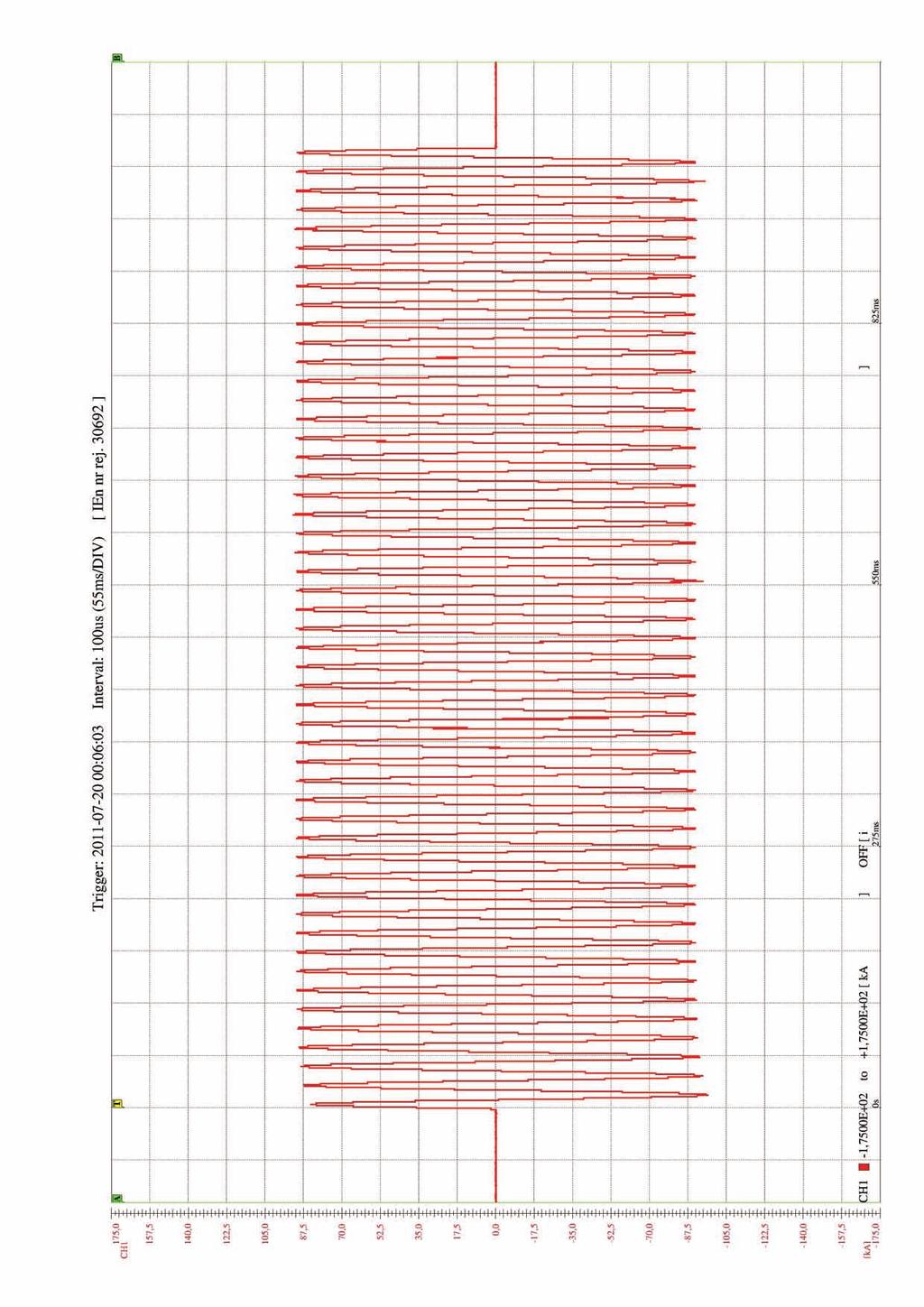
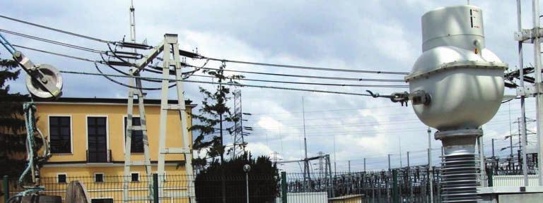
8 EUR/33/E/11-2E Page 7/16 4. TESTS AND THEIRS DETAILED RESULTS Mechanical tests were performed and short-circuit tests - in the nights 19/20.07, 08/ Tests results present tables 1, 2 and 3. During the tests the following records were made: - No calibration of measuring circuit, - Nos , short-circuit withstand capability tests, - Nos , 30727, calibration of test circuit, - Nos , 30728, short-time current tests, (Annex 1 presents the copies of short-circuit test records - all records are stored in laboratory s archives), - phot. 1 to 4 combined transformer on short-circuit tests stand, - phot. 5 to 10 - combined transformer during mechanical tests (Annex 2 presents the photographs). Table 1. Results of static load withstand tests at F = 3620 N and dynamic *) Test Load Test Terminal Observations No. direction time s P1 P1 P1 P1 P1 P1 P2/A P2/A P2/A P2/A transverse transverse vertical vertical longitudinal longitudinal transverse transverse vertical vertical 60 dyn. *) 60 dyn. *) 60 dyn. *) 60 dyn. *) 60 dyn. *) After tests no damage nor oil leak was stated. After tests no damage nor oil leak was stated. After tests no damage nor oil leak was stated. After tests no damage nor oil leak was stated. After tests no damage nor oil leak was stated. 11 P2/A longitudinal 60 After tests no damage nor oil leak was stated. 12 P2/A longitudinal dyn. *) Remark: *) Dynamic tests were performed by sudden loading the terminal by the weight 3620 N.
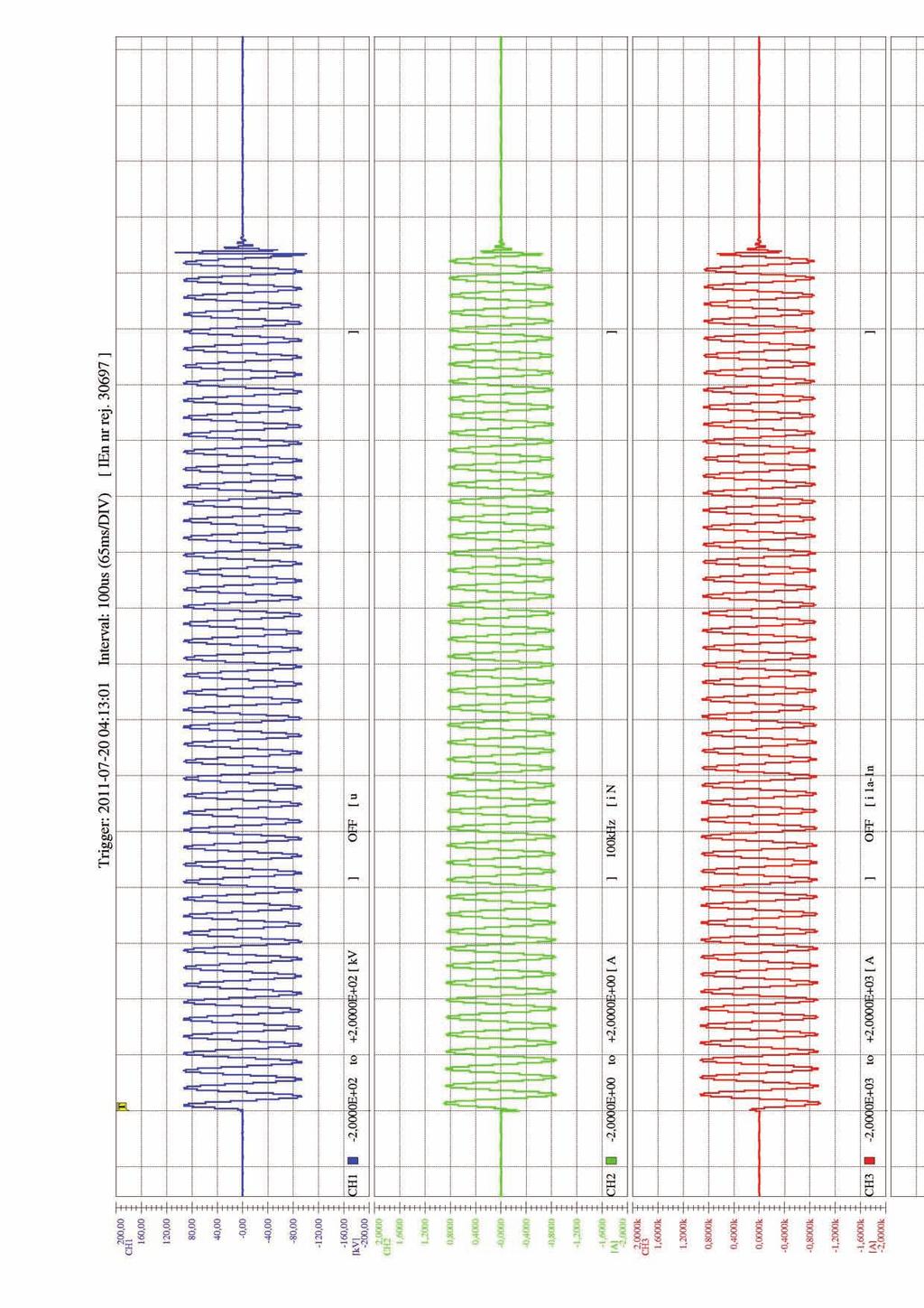
9 EUR/33/E/11-2E Page 8/16 Table 2. Results of short-circuit withstand capability tests (t amb = 20 C) Test No. Terminals U z I PS I SS t z Observations - kv A A s a 1n 65,4 1) 0, ,0 After tests no damage nor oil leak was stated da - dn 65,5 1) 0, ,0 After tests no damage nor oil leak was stated. Legend: U z - test voltage I PS - r.m.s. value of primary side test current I SS - r.m.s. value of secondary side test current t z - test duration 1) - required U z 63,5 kv Table 3. Results of short-time current tests (t amb = 16 C) Test No. Term. i pesk I z t z I z 2 t z Observations - - ka ka s (ka) 2 s A 27,0 1) 10,4 1, ) After tests no damage nor oil leak was stated A 54,4 3) 20,8 1, ) After tests no damage nor oil leak was stated A 102,7 5) 40,5 1, ) After tests no damage nor oil leak was stated. Legend: i peak - peak value of test current - r.m.s. value of test current I z t z - test duration Required : 1) - i peak 25 ka, 2) - I 2 z t z 100 (ka) 2 s 3) - i peak 50 ka, 4) - I 2 z t z 400 (ka) 2 s 5) - i peak 100 ka, 6) - I 2 z t z 1600 (ka) 2 s 5. TESTS RESULTS EVALUATION According to criteria given in EN :2003 (idt IEC :2002) p. 6.2 a), 6.2 f) i 6.4 d) the results of tests of tested combined transformer is positive for: - I th = 10 ka, I dyn = 25 ka for 50 A terminal, - I th = 20 ka, I dyn = 50 ka for 100 A terminal, - I th = 40 ka, I dyn = 100 ka for 200 A terminal, - 63,5 kv at short-circuit in secondary circuits of voltage transformer, - F R = 3600 N and resulting dynamic load.
10 EUR/33/E/11-2E Page 9/16 ANNEX 1 Test records As not numbered pages the following copies of records are given: 30697, voltage transformer tests 30726, 30728, current transformer tests Denotations: u 110 test voltage during voltage transformer tests i N test current on primary side of VT i 1a-1n, i da-dn test current on secondary side of VT i test current during current transformer tests
11
12
13
14
15


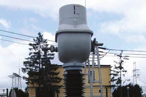
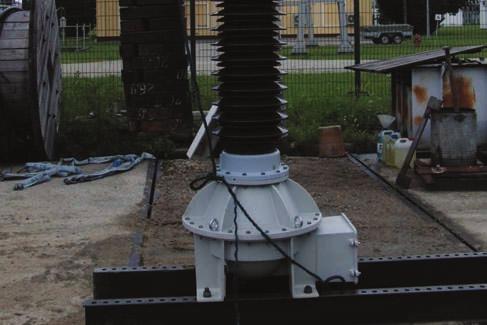
16 EUR/33/E/11-2E Page 10/16 ANNEX 2 Photographs taken during the tests Phot. 1. PVA 123 after short-time current tests of VT Phot. 2. PVA 123 after short-circuit withstand capability tests of CT 50 A


17 EUR/33/E/11-2E Page 11/16 Phot. 3. PVA 123 after short-circuit withstand capability tests of CT 100 A Phot. 4. PVA 123 after short-circuit withstand capability tests of CT 200 A


18 EUR/33/E/11-2E Page 12/16 Phot. 5. Transverse load of terminal P1 Phot. 6. Transverse load of terminal P2/A 200 A
19 EUR/33/E/11-2E Page 13/16 Phot. 7. Vertical load of terminal P1 Phot. 8. Vertical load of terminal P2/A 200 A


20 EUR/33/E/11-2E Page 14/16 Phot. 9. Longitudinal load of terminal P1 Phot. 10. Longitudinal load of terminal P2/A 200 A
21 EUR/33/E/11-2E Page 15/16 ANNEX 3 Documentations delivered by orderer
22 EUR/33/E/11-2E Page 16/16
23
24 EUR/33/E/11-1E Page 2/13 Contents Page 1. Test object Description Technical data Technical documentation Preparation for tests 3 2. Scope of tests 3 3. Test and measuring circuits 3 4. Tests and theirs detailed results 5 5. Test results evaluation 6 Annexes: 1. Short-circuit test records 2. Photographs taken during the tests 3. Documentations delivered by orderer Report contents: numbered pages 13 records (pages not numbered) 2 tables 2 figures 2 photographs 7
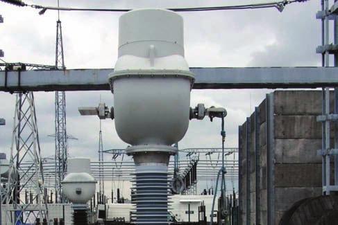
25 EUR/33/E/11-1E Page 3/13 1. TEST OBJECT 1.1 Description Combined transformer type PVA 123 is used for supplying of measuring and protection circuits in the network of nominal voltage 110 kv and frequency 50 Hz. The transformer consists of current and voltage transformers mounted in common composite enclosure immersed with transformer oil. 1.2 Technical data The Manufacturer attributed the following construction data to the test object. Rated voltage Rated frequency Rated continuous thermal current Rated short-time current Rated dynamic current Rated static load 110/ 3 kv 50 Hz 3000 A 63 ka 158 ka 3600 N 1.3 Technical documentation For the purpose of tests the orderer delivered the following technical documentation: - dimension drawing of combined transformer PVA 123, No.2GKK , ABB Sp. z o.o., (Annex 3), - electrical diagram of combined transformer PVA 123, ABB Sp. z o.o., (Annex 3). The laboratory proceeded the identification of test object on the base of above documentation and the nameplate. 1.4 Preparation for tests The test object was prepared for test by factory. 2. SCOPE OF TESTS Test program, agreed with orderer, comprised the following tests according to requirements of EN :2003 (idt IEC :2002): - short-time current tests of current transformer acc. to item 6.2 a) of above standards at parameters: I dyn 158 ka, I th = 63 ka t th = 1 s, I th 2 t th 3969 ka 2 s, - mechanical tests acc. to item 6.4 d) of above standards for F R = 3600 N and resulting dynamic load. 3. TEST AND MEASURING CIRCUITS For the tests the transformer was fixed to the rigid construction of the test stand. Short-time current tests were made in one phase circuit presented on fig. 1 and 2. Mechanical tests were performed applying the load consecutively to the transformer s terminals as shown on photographs 2 to 7 in Annex 2. The following quantities were recorded during the tests using digital recorder type HIOKI 8842: primary current of current transformer (with short-circuited all secondary terminals) during short-time current tests using laboratory current transformer type CdC class 0,5 with a ratio /2 A/A
26 EUR/33/E/11-1E Page 4/ kv L1 L2 T CB T - short-circuit transformer CB - back-up circuit-breaker R - reactor MS - make switch CT - current transformer TO - test object R MS CT Recorder HIOKI 8842 TO Fig.1. Test and measuring circuits during short-time current tests
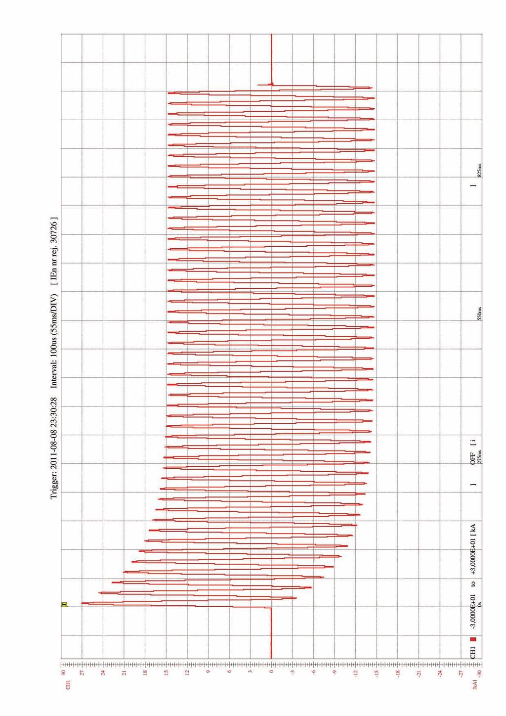
27 EUR/33/E/11-1E Page 5/ mm 1400 mm 1000 mm 2 AFL mm 2 AL 1000 mm mm 3600 mm 3300 mm Fig. 2. Configuration of test circuit during short-time current tests 4. TESTS AND THEIRS DETAILED RESULTS Short-circuit tests were performed in the night 19/ and mechanical tests Tests results present tables 1 and 2. During the tests the following records were made: - No calibration of measuring circuit, - Nos , calibration of test circuit, - No , short-time current tests, (Annex 1 presents the copies of short-circuit test records - all records are stored in laboratory s archives), - phot. 1 combined transformer on short-circuit tests stand, - phot. 2 to 7 - combined transformer during mechanical tests (Annex 2 presents the photographs). Table 1. Results of short-time current tests (t amb = 20 C) Test No. i pesk I z t z I z 2 t z Observations - ka ka s (ka) 2 s ,5 63,7 1, ) was correct. After tests no damage nor oil Behaviour of transformer during the tests leak was stated ,2 2) 63,9 0,06 - Behaviour of transformer during the tests was correct. After tests no damage nor oil leak was stated. Legend: i peak - peak value of test current - r.m.s. value of test current I z t z - test duration Required : 1) - I 2 z t z 3969 (ka) 2 s 2) - i peak 158 ka
28 EUR/33/E/11-1E Page 6/13 Table 2. Results of static load withstand tests at F = 3620 N and dynamic *) Test Load Test Terminal Observations No. direction time s P1 P1 P1 P1 P1 P1 P2/A P2/A P2/A P2/A P2/A P2/A transverse transverse vertical vertical longitudinal longitudinal transverse transverse vertical vertical longitudinal longitudinal 60 dyn. *) 60 dyn. *) 60 dyn. *) 60 dyn. *) 60 dyn. *) 60 dyn. *) Behaviour of transformer during the tests was correct. After tests no damage nor oil leak was stated. Behaviour of transformer during the tests was correct. After tests no damage nor oil leak was stated. Behaviour of transformer during the tests was correct. After tests no damage nor oil leak was stated. Behaviour of transformer during the tests was correct. After tests no damage nor oil leak was stated. Behaviour of transformer during the tests was correct. After tests no damage nor oil leak was stated. Behaviour of transformer during the tests was correct. After tests no damage nor oil leak was stated. Remark: *) Dynamic tests were performed by sudden loading the terminal by the weight 3620 N. 5. TESTS RESULTS EVALUATION According to criteria given in EN :2003 (idt IEC :2002) p. 6.2 a), and 6.4 d) the results of tests of tested combined transformer is positive for: - I th = 63 ka, I dyn = 158 ka for current transformer, - F R = 3600 N and resulting dynamic load..
29 EUR/33/E/11-1E Page 7/13 ANNEX 1 Test records As not numbered pages the following copies of records are given: 30690, current transformer tests Denotations: i test current
30
31

32 EUR/33/E/11-1E Page 8/13 ANNEX 2 Photographs taken during the tests Phot. 1. PVA123 after short-time current tests of CT


33 EUR/33/E/11-1E Page 9/13 Phot. 2. Transverse load of terminal P1 Phot. 3. Transverse load of terminal P2/A
34 EUR/33/E/11-1E Page 10/13 Phot. 4. Vertical load of terminal P1 Phot. 5. Vertical load of terminal P2/A
35 EUR/33/E/11-1E Page 11/13 Phot. 6. Longitudinal load of terminal P1 Phot. 7. Longitudinal load of terminal P2/A

36 EUR/33/E/11-1E Page 12/13 ANNEX 3 Documentations delivered by orderer
37 EUR/33/E/11-1E Page 13/13
Fuse-links type CEF-S Rated voltages: 6/12 kv 30/40.5 kv Rated currents: 6.3 A 63 A
 DISTRIBUTION SOLUTIONS Fuse-links type CEF-S Rated voltages: 6/12 kv 30/40.5 kv Rated currents: 6.3 A 63 A Superior performance versus standard fuses ensuring up to 40% faster protection in case of low
PowerIT Indoor Voltage Transformer Fuses, WBP. Outdoor Voltage Transformer Fuses, BRT. Catalogue 1YMB en. Industrial IT.
 PowerIT PowerIT Indoor Voltage Transformer Fuses, WBP Outdoor Voltage Transformer Fuses, BRT Catalogue 1YMB612070-en Industrial IT enabled TM 1. FEATURES Unlimited breaking capacity Short circuit current
Fuse-links type CEF-VT Rated voltages 3/7.2 kv - 10/24 kv Rated current 0.5 A 6.3 A
 DISTRIBUTION SOLUTIONS Fuse-links type CEF-VT Rated voltages 3/7.2 kv - 10/24 kv Rated current 0.5 A 6.3 A Efficient protection of voltage transformer circuits Extending the lifetime of installed electrical
1ZSE EN, REV. 7. Oil SF 6. bushings type GOEK Technical guide
 1ZSE 2750-106 EN, REV. 7 Oil SF 6 bushings type GOEK Technical guide Original instruction The information provided in this document is intended to be general and does not cover all possible applications.
Transformer bushings, type GOH. Technical guide
 Transformer bushings, type GOH Technical guide This Technical Guide has been produced to allow transformer manufacturers, and their designers and engineers, access to all the technical information required
Resin Impregnated Paper Bushing, Oil to SF 6. , Type GSBK
 1ZSC563-AAA en, Rev. 2 Resin Impregnated Paper Bushing, Oil to SF 6, Type GSBK Technical guide This Technical Guide has been produced to allow transformer manufacturers, and their designers and engineers,
1ZSC AAA en, Rev. 6. Resin impregnated paper bushing, oil to SF 6., type GSBK Technical guide
 1ZSC563-AAA en, Rev. 6 Resin impregnated paper bushing, oil to SF 6, type GSBK Technical guide Original instruction The information provided in this document is intended to be general and does not cover
PHOENIX CONTACT
 Current transformers INTERFACE Data sheet 03359_en_03 PHOENIX CONTACT 20-04-04 Description The PACT Analog current transformers form a complete range of bus-bar, plug-in and winding current transformers
Outdoor live tank vacuum circuit breaker Type OVB-VBF for 24/36/40.5 kv applications
 Outdoor live tank vacuum circuit breaker Type OVB-VBF for 24/36/40.5 kv applications ABB a global leader ABB is a global leader in power and automation technologies that enable utility and industry customers
CATALOGUE. ON Medium Voltage Outdoor Disconnectors
 CATALOGUE ON Medium Voltage Outdoor Disconnectors 2 O N M E D I U M V O LTA G E O U T D O O R D I S C O N N E C TO R S ON MEDIUM VOLTAGE OUTDOOR DISCONNECTORS 3 Table of conteants 004 1. Introduction 004
Current accuracy class. Sensor principles
 Indoor Combi Sensor 12, 17.5 and 25 kv 1250 A and 3200 A KEVCD Highest voltage for equipment kv 12.24 Rated continuous primary current A 1250.3200 Rated transformation ratio for current measurement, K
MS /27/2015. ABB contact for United States of America. General Information Extended Product Type: Categories
 Page 1 of 5 MS132-10 ABB contact for United States of America General Information Extended Product Type: Product ID: EAN: Catalog Description: Long Description: MS132-10 1SAM350000R1010 4013614400100 MS132-10
System pro M compact Supplementary protector S 200 PR for ring-tongue applications acc. to UL1077
 Data Sheet System pro M compact Supplementary protector S 200 PR for ring-tongue applications acc. to UL1077 2CDC021026S0011 2CDC021016S0012 The S 200 PR is a high-performance supplementary protector with
Motorized switch-disconnectors OTM 40 to 125 Amperes
 Motorized switch-disconnectors OTM to 125 mperes With the new range of motorized-switch disconnectors, BB offers now a full range from to 2500 mperes. Thanks to the design, OTM...125 are a good solution
Resin Impregnated Paper Bushing, Oil to Air, Type GSB Technical guide
 1ZSC000563-AAC en, Rev. 2 Resin Impregnated Paper Bushing, Oil to Air, Type GSB Technical guide This Technical Guide has been produced to allow transformer manufacturers, and their designers and engineers,
Electronic overload relays EF205 and EF370
 Data sheet Electronic overload relays EF205 and EF370 Electronic overload relays offer reliable protection in case of overload and phase-failure. They are the alternative to thermal overload relays. Motor
The breakers offer thermal-magnetic trip protection according to Z and K characteristics.
 Series High Performance Circuit Breakers Description The high performance MCB offers a compact solution to circuit protection. The devices are DIN rail mounted. The is available with application-specific
1ZSC AAA EN, REV. 7. Transformer bushings type GSBK Technical guide
 1ZSC563-AAA EN, REV. 7 Transformer bushings type GSBK Technical guide Original instruction The information provided in this document is intended to be general and does not cover all possible applications.
DCX-M. changeover switches ->CATALOGUE PAGES INSIDE THE GLOBAL SPECIALIST IN ELECTRICAL AND DIGITAL BUILDING INFRASTRUCTURES
 DCX-M changeover switches ->CATALOGUE PAGES INSIDE THE GLOBAL SPECIALIST IN ELECTRICAL AND DIGITAL BUILDING INFRASTRUCTURES FOR COMMERCIAL BUILDINGS AND DCX-M In = 63 A Quality & design CONFORM TO EN/IEC
SWITCHGEAR FOR SERVICE UP TO 36kV (CABLE AND OVERHEAD CONDUCTOR CONNECTED)
") PRODUCED BY THE OPERATIONS DIRECTORATE OF ENERGY NETWORKS ASSOCIATION Issue 3 2012 SWITCHGEAR FOR SERVICE UP TO 36kV (CABLE AND OVERHEAD CONDUCTOR CONNECTED) www.energynetworks.org 2012 Energy Networks
PRODUCED BY THE OPERATIONS DIRECTORATE OF ENERGY NETWORKS ASSOCIATION Issue 3 2012 SWITCHGEAR FOR SERVICE UP TO 36kV (CABLE AND OVERHEAD CONDUCTOR CONNECTED) www.energynetworks.org 2012 Energy Networks
KOLMA and IHDA Indoor Type Cable Current Transformers. Catalogue. Catalogue KOLMA 1 GB Medium Voltage. ABB Transmit KKOLMA 1 GB
 Catalogue KOLMA and IHDA Indoor Type Cable Current Transformers Catalogue KOLMA 1 GB 99-05 Medium Voltage ABB Transmit 1 KKOLMA 1 GB KOLMA and IHDA Indoor Type Cable Current Transformers Index Description...
Miniature circuit-breaker (MCB) SH200M Series
 SH200M Series") Miniature circuit-breaker (MCB) SH200M Series 25 mm² cage terminals, a well proven and reliable technology. IP20 - finger safety. Scratch and solvent resistant marking due to laser printing. Easy identification
Miniature circuit-breaker (MCB) SH200M Series 25 mm² cage terminals, a well proven and reliable technology. IP20 - finger safety. Scratch and solvent resistant marking due to laser printing. Easy identification
Pantograph disconnector type GW54, up to 550 kv Maximum reliability and minimal maintenance
 Pantograph disconnector type GW54, up to 550 kv Maximum reliability and minimal maintenance Table of contents 02 03 04 05 06 07 08 Disconnectors from ABB Maximum reliability and minimal maintenance Technical
Switches for photovoltaic applications Disconnect switches, UL OTDC_U from 16 to 32 Amperes
 Switches for photovoltaic applications Disconnect switches, UL OTDC_U from 16 to 32 Amperes OTDC16...32U - Compact efficiency OTDC from 16 to 32 amperes offers various DC voltage ratings and a control
System pro M compact Miniature Circuit Breaker SU200M for branch circuit protection acc. to UL 489
 System pro M compact Miniature Circuit Breaker SU200M for branch circuit protection acc. to UL 489 2CDC021004S0014 2CDC021046S0014 The miniature circuit breaker SU 200 M is ABB s solution for UL 489 branch
020: 2013 CEB SPECIFICATION MINIATURE CIRCUIT BREAKER (MCB)
") 020: 2013 CEB SPECIFICATION MINIATURE CIRCUIT BREAKER (MCB) CEYLON ELECTRICITY BOARD SRI LANKA Telephone: +94 11 232 0953 Fax: +94 11 232 3935 CONTENTS Page 1.0 Scope 3 2.0 System Parameters 3 3.0 Service
020: 2013 CEB SPECIFICATION MINIATURE CIRCUIT BREAKER (MCB) CEYLON ELECTRICITY BOARD SRI LANKA Telephone: +94 11 232 0953 Fax: +94 11 232 3935 CONTENTS Page 1.0 Scope 3 2.0 System Parameters 3 3.0 Service
Compact Integrated Distribution Substation (CIDS)
") Compact Integrated Distribution Substation (CIDS) 1- INTRODUCTION SAVE SPACE 2.5m 2 footprint for CIDS up to 630kVA. SAVE THE ENVIRONMENT No SF6, No PCB. SAVE MONEY Save up to 50% from conventional package
Compact Integrated Distribution Substation (CIDS) 1- INTRODUCTION SAVE SPACE 2.5m 2 footprint for CIDS up to 630kVA. SAVE THE ENVIRONMENT No SF6, No PCB. SAVE MONEY Save up to 50% from conventional package
10/2015 CUBICLE AND METAL-CLAD MEDIUM VOLTAGE SWITCHGEARS WEGA 07 WEGA 12 WEGA 17 WEGA 24 WEGA 36
 10/2015 CUBICLE AND METAL-CLAD MEDIUM VOLTAGE SWITCHGEARS WEGA 07 WEGA 12 WEGA 17 WEGA 24 WEGA 36 Gdańsk, October 2015 Improving the competitiveness of the company ELMOR through investments introducing
013 : 2009 CEB SPECIFICATION MOULDED CASE CIRCUIT BREAKERS
 013 : 2009 CEB SPECIFICATION MOULDED CASE CIRCUIT BREAKERS FOR OVERHEAD NETWOKS CEYLON ELECTRICITY BOARD SRI LANKA Specification for MOULDED CASE CIRCUIT BREAKERS FOR OVERHEAD NETWOKS CEB Specification
Electronic overload relay EF65, EF96 and EF146
 Data sheet Electronic overload relay EF65, EF96 and EF146 Electronic overload relays are the alternative to the thermal overload relays. An electronic overload relay offers reliable and fast protection
Mini contactors B6, BC6 with 3 pole
 Data sheet Mini contactors B6, BC6 with 3 pole Mini contactors from ABB are used for remotely ling motors and other loads wherever space is at a premium. These devices feature hum free coils, shallow depth,
Surge arrester POLIM-H..SD
 Data sheet Surge arrester POLIM-H..SD Technical data Classification according to EN 50526-1 and IEC 62848-1 Nominal discharge current I n (8/20 µs) 10 ka peak Class DC-B High current impulse I hc (4/10
1ZSE en, Rev. 3. Wall bushings, type GSA-AA Technical guide
 1ZSE 2750-112 en, Rev. 3 Wall bushings, type GSA-AA Technical guide Original instruction The information provided in this document is intended to be general and does not cover all possible applications.
Retrofit for gas-insulated high voltage switchgear (GIS) - 8D1 and 8D2
 - 8D1 and 8D2") Retrofit for gas-insulated high voltage switchgear (GIS) - 8D1 and 8D2 Table of Contents 1 Introduction... 4 2 Description of retrofit circuit-breaker 8DN8... 5 3 Technical data for retrofit circuit-breaker
Retrofit for gas-insulated high voltage switchgear (GIS) - 8D1 and 8D2 Table of Contents 1 Introduction... 4 2 Description of retrofit circuit-breaker 8DN8... 5 3 Technical data for retrofit circuit-breaker
Dead Tank Circuit Breaker 145PM40-C Compact design with enhanced reliability
 Dead Tank Circuit Breaker 145PM40-C Compact design with enhanced reliability ABB innovations for changing demands ABB (www.abb.com) is a leader in power and automation technologies that enables utility
Current transformers. Current transformers
 Current transformers Current transformers Moulded case current transformer Moulded case CT, class 1 and 0.5 / 5 A Increased reliability Both halves of the housing overlap rather than butting up against
All rights reserved. Neither this catalogue nor any part of it may be copied using any method or for any purposes. Most studies are legally protected.
 Issued: January 2013 Copyright by ZPUE Katowice S.A. All rights reserved. Neither this catalogue nor any part of it may be copied using any method or for any purposes. Most studies are legally protected.
Medium Voltage. KOFD Indoor Type Current Transformers Cast Resin Insulated. Catalogue. 12, 13.8, 17.5, 24 and 36 kv KOFD 1 GB
 Catalogue Indoor Current Transformers Cast Resin Insulated 1, 13.8, 17.5, 4 and 36 kv 97-1 96-1054 Medium Voltage 1 Indoor Current Transformers Cast Resin Insulated 1, 13.8, 17.5, 4 and 36 kv Index Description...
24kV Medium Voltage Switchgear Metal-Enclosed (LSC2A)
") M6 24kV Medium Voltage Switchgear MetalEnclosed (LSC2A) GENERAL FEATURES GENERAL DESCRIPTION The structure of the cubicles, of considerable strength, has selfsupporting structure and is made of steel sheet
M6 24kV Medium Voltage Switchgear MetalEnclosed (LSC2A) GENERAL FEATURES GENERAL DESCRIPTION The structure of the cubicles, of considerable strength, has selfsupporting structure and is made of steel sheet
Medium voltage fuses - European Fuses
 HV Back-up Fuse-Links according to IEC 60 282- HV fuse-links have been used for reliable protection in medium-voltage switchgear and controlgear and systems for decades. They protect apparatus and equipment
On-load tap-changer OILTAP V
 www.reinhausen.com On-load tap-changer OILTAP V Technical Data TD 82/03 Table of Contents Table of Contents 1 General... 4 1.1 Summary of the technical data... 4 1.2 Survey... 6 2 Technical Data... 13
1ZSE en, Rev. 7. Transformer bushings, type GOB Technical guide
 1ZSE 2750-102 en, Rev. 7 Transformer bushings, type GOB Technical guide This Technical Guide has been produced to allow transformer manufacturers, and their designers and engineers, access to all the technical
MV Air Insulated Switchgear TAP17. Technical Data TGOOD
 MV Air Insulated Switchgear TAP17 Technical Data TGOOD 2017.1 Operating environmental conditions Place of installation: Indoor or outdoor Ambient temperature: 25 ~ +40 (higher or lower temperature optional)
GE Electrical Distribution. Gerapid High Speed DC Circuit Breakers. On the move. imagination at work
 GE Electrical Distribution Gerapid High Speed DC Circuit Breakers On the move imagination at work Gerapid High Speed DC Circuit Breakers To stay up and running today, you need equipment that delivers both
ZX-Family Gas-insulated medium voltage switchgear
 ZX-Family Gas-insulated medium voltage switchgear Minimum overall costs ZX offers maximum economy The compact design of the panels reduces the space required and therefore the size of the station. Freedom
Product brochure Generator circuit-breaker HVS-63S System type GCB with innovative built-in monitoring
 Product brochure Generator circuit-breaker HVS-63S System type GCB with innovative built-in monitoring ABB is a leader in power and automation technologies that enable utility and industry customers to
CP Automatic capacitor bank
 CP 254 - Automatic capacitor bank STE-CP254_V2_général.doc Page 1 CP 254 - General presentation CP 254 is a range of MV capacitor banks designed to be used in electrical networks up to 36kV. The capacitor
High-voltage high-breaking capacity VV fuse-links
 High- high- VV fuse-links [A] (ka) [mω] [W] [A 2 s] [A 2 s] 12 580 4 6,1 57 4 A 20 370 9 17,3 164 6 A 25 260 10 36 340 10 A 46 55 7 161 1 530 16 A 60 37 13 250 2 270 20 A 80 30 15 430 3 750 25 A 105 25
Medium-voltage fuses 3 kv 40.5 kv, 0.4 A 315 A
 DISTRIBUTION SOLUTIONS Medium-voltage fuses 3 kv 40.5 kv, 0.4 A 315 A Continuous protection and reliable operation Proven design and compliance with newest fuses standards Compatibility with other ABB
High voltage current limiting Fuse links type CEF
 High voltage current limiting Fuse links type CEF Index 1. General........................................... 9 2. Overvoltages...................................... 9 3. Pre-arcing times and cut-off characteristics..............
Company Overview. Since 1975 in the sector, solid experience of design and production of dry type electric transformers and inductances
 COMPANY PROFILE Company Overview Since 1975 in the sector, solid experience of design and production of dry type electric transformers and inductances GEOGRAPHIC SCOPE QUALITY GUARANTEED Trasfeco produces
Technical Specification of GECOL. Packaged Transformers
 GES 26211 Technical Specification of GECOL Packaged Transformers (Revision history) Issued on: Jan. 01, 2007 General Electricity Company of Libya Contents 1 SCOPE AND SERVICE CONDITIONS... 6 1.1 SCOPE...
MESG 12 / 17.5 / 24 / 36 KV
 MESG 12 / 17.5 / 24 / 36 KV Medium Voltage Air Insulated Metal Enclosed Switchgear up to 36 kv- up to 1250 A - up to 25 ka for 1 sec. with SF6 or vacuum circuit breakers. 750 METAL ENCLOSED 1 1 ) GENERAL
B kv Gas-insulated Substations
 72.5 145 kv Gas-insulated Substations The increasing demand for electrical power in cities and industrial centres requires the installation of a compact and efficient distribution and transmission network.
TECHNICAL SPECIFICATION FOR 11 KV AUTOMATIC CAPACITOR SWITCH
 TECHNICAL SPECIFICATION FOR 11 KV AUTOMATIC CAPACITOR SWITCH MAHARASHTRA STATE ELECTRICITY DISTRIBUTION COMPANY LTD. PAGE 1 OF 7 TECHNICAL SPECIFICATION FOR 11 KV AUTOMATIC CAPACITOR SWITCH 1.0 SCOPE:
Prüffeld der Schaltwerke
 Report No.: 16-043-MS Sheet: 2 Notes 1. The testing station of the Siemens switchgear factory (Prüffeld der Schaltwerke),, Berlin, has been approved by the DAkkS (German accreditation body) for rendering
MS General Information Extended Product Type: MS
 MS132-1.6 General Information Extended Product Type: MS132-1.6 Product ID: 1SAM350000R1006 EAN: 4013614400063 Catalog Description: MS132-1.6 Manual Motor Starter Long Description: The MS132-1.6 manual
High voltage products PASS M0S 252 kv Innovative solution for transmission substation up to 252 kv
 High voltage products PASS M0S 252 kv Innovative solution for transmission substation up to 252 kv PASS M0S 252 kv Innovation In today s market, the HV substation is increasingly becoming a key element
HMI, APRIL, Test Laboratories in Ratingen
 HMI, 24.-28. APRIL, 2017 Test Laboratories in Ratingen Test Laboratories Ratingen Overview Basic Features Flexible Independent Well experienced in testing of medium and low voltage equipment (testing since
High-Voltage Fuse Links according to IEC
 High-Voltage Fuse Links according to IEC 60282- Limitor Ferraz Shawmut is global leader in fuse-based electrical protection solutions. Our brand is worldwide renowned for technical expertise, innovative
Air-insulated switchgear UniGear type ZS1
 Air-insulated switchgear UniGear type ZS1 ABB Power Technologies / 1-7074 D 12-03-2003 - Air-insulated switchgear UniGear type ZS1 ABB Power Technologies / 2-7075 D 1 2-03-2003 - Rated voltage kv 12 17.5
Current sensor. Instructions for installation, use and maintenance. Type KECR 17,5 AC1 ABB
 Current sensor Instructions for installation, use and maintenance Type KECR 17,5 AC1 ABB Current sensor Instructions for installation, use and maintenance Type KECR 17,5 AC1 Sensors are new solutions for
Protection and Connection Motorized and automatic transfer switches IEC Technical guide
 Protection and Connection Motorized and automatic transfer switches IEC 61439 Technical guide Motorized change-over switches Uninterrupted power supply with motorized functionality ABB offers a wide variety
Circuit breakers and switch-disconnectors NT06 to NT16 and NW08 to NW63
 Functions and characteristics Circuit breakers and switch-disconnectors NT06 to NT16 and NW08 to NW63 NT and NW selection criteria Masterpact NT Masterpact NW NT06, NT08, NT10, NT12, NT16 NT06, NT08, NT10
e 2 ALPHA Medium Voltage Switchgear K Catalogue EN
 e 2 ALPHA Medium Voltage Switchgear K-1.2.3 Catalogue EN WE CREATE IDEAS WITH POWER! ELEKTROMETAL ENERGETYKA SA provides solutions for electrical power engineering. Our services are carried out by a team
ATLV MaxSG. Low Voltage Metal Enclosed Switchgear
 ATLV MaxSG Low Voltage Metal Enclosed Switchgear ABB, INC. Product General Description MaxSG Switchgear ABB MaxSG switchgear is a further continuation in the development of innovative products from ABB,
Product Brochure. Generator Circuit-Breaker HVR-EBCB For hydro or pump storage power plant
 Product Brochure Generator Circuit-Breaker HVR-EBCB For hydro or pump storage power plant Introduction General The braking switch serves the purpose of electrical braking a machine in a hydro or pumped
1ZSE en, Rev. 9. Transformer bushings, type GOB Technical guide
 1ZSE 2750-102 en, Rev. 9 Transformer bushings, type GOB Technical guide Original instruction The information provided in this document is intended to be general and does not cover all possible applications.
HV reed relays K-551H, K-552H K-553H, K-554H, K-555H. form A contact (normally open) for PCBs
 for PCBs") HV reed relays K-55H, K-55H K-55H, K-55H, K-555H PIT-RADWAR S.A. 50-5 Wrocław, ul. Krakowska 6, Poland tel. (+8) 7/-65-5, fax (+8) 7/-58-59.CONTACT K-55H K-55H K-55H K-55H K-555H Switching power max W,
HV reed relays K-55H, K-55H K-55H, K-55H, K-555H PIT-RADWAR S.A. 50-5 Wrocław, ul. Krakowska 6, Poland tel. (+8) 7/-65-5, fax (+8) 7/-58-59.CONTACT K-55H K-55H K-55H K-55H K-555H Switching power max W,
Gas-Insulated Switchgear. Type 8VN1 blue GIS up to 145 kv, 40 ka, 3150 A
 Gas-Insulated Switchgear Type 8VN1 blue GIS up to 145 kv, 40 ka, 3150 A siemens.com/energy-management Table of content Gas-insulated switchgear Product portfolio 72.5 550 kv Vacuum interrupters for switching
 15 16 MCCBs for Power Distribution Technical Specification Frame 100A 250A 250A 400A 400A 630A 800 / 1000 / 1250 Type C DN0-100 D DN1-250 N DN2-250 D N S H DN3B-400 DN3-400 D N D N S V DN3-630 DN4-1250
CGMCOSMOS Fully gas-insulated modular and compact (RMU) system Up to 24 kv
 system Up to 24 kv") Medium Voltage Switchgear Secondary Distribution CGMCOSMOS Fully gas-insulated modular and compact (RMU) system MV Switchgear Secondary Distribution Networks General description Introduction Ormazabal
Medium Voltage Switchgear Secondary Distribution CGMCOSMOS Fully gas-insulated modular and compact (RMU) system MV Switchgear Secondary Distribution Networks General description Introduction Ormazabal
Panel SCCR 50kA RMS Symmetrical 480V Maximum
 Panel SCCR 50kA RMS Symmetrical 480V Maximum 4 Short-Circuit Current Rating SCCR: The perspective or maximum symmetrical fault current at a nominal voltage to which an apparatus or system is able to be
Technical Data Accessories MCBs Ex9B.
 Auxiliary and signal contact units AX31, A31, AX31 General parameters With one circuit breaker Ex9B., it can be used up to three contact units with single CO contact or up to two contact units with 2 CO
TEKNISK RIKTLINJE TR05-10E
 Notes Change notes Date 1 (A) Revision of standards and new template 09 / 07 2010 2 Template changed.clause. 10.5.1.4 support clamp inserted. Clause 10.5.4.2 creepage text revised. Clause 10.6.7 Dry inserted
KECA 80 C85 Current Sensor Instructions for installation, use and maintenance
 Medium Voltage Products KECA 80 C85 Current Sensor Instructions for installation, use and maintenance 1. Operating conditions 2 2. Technical details 2 3. Instructions for installation 3 Safety instruction
Scheda prodotto Relè Series E
 Relè Miniatura All-or-Nothing relays ideally suited for any electronic appliances demanding very compact design and low power consumption. Design includes a protective dust cover and a completete range
Technical information
 Technical information General Regulations WTL current transformers are special transformers which transfer the primary circuits with prescribed accuracy in smaller secondary circuits. Primary and secondary
Application Note: Protection of Medium-Power Motors With SIPROTEC Compact 7SK80
 Application Note: Protection of Medium-Power Motors With SIPROTEC Compact 7SK80 Motor settings using the SIPROTEC Compact motor protection relay 7SK80 is explained below. Information is given on how to
Ultra Fast Earthing Switch UFES retrofit Overview
 Gordon van der Linde ABB PTMV - Service Ultra Fast Earthing Switch UFES retrofit Overview May 20, 2013 UFES Slide 1 Ultra Fast Earthing Switch UFES retrofit Content 1. Effects of an internal arc 2. The
Semiconductor (AC) fuses
 fuses") Main characteristics 450 TO 700VAC / 63 TO 2800A Recognized Exceptionally low I 2 T, Watt losses. Non-magnetic construction, Highly reliable low voltage Trip-indicator system, conformity to UL, IEC, DIN
Main characteristics 450 TO 700VAC / 63 TO 2800A Recognized Exceptionally low I 2 T, Watt losses. Non-magnetic construction, Highly reliable low voltage Trip-indicator system, conformity to UL, IEC, DIN
www. ElectricalPartManuals. com Miniature Circuit Breakers Section 7
 EP60 Series...7-2 EP100 Series...7-4 EP100 ULH Series...7-6 EP100 UC Series (Branch Circuit Protection)...7-8 Series CA Auxiliary Switch and Bell Alarm...7-10 Series CB Auxiliary Switch and Bell Alarm...7-11
PROTECTION AND CONNECTION. ABB Compact ATS Compact without compromise
 PROTECTION AND CONNECTION ABB Compact ATS Compact without compromise 2 A B B C O M PA C T AT S C O M PA C T W I T H O U T C O M P R O M I S E ABB ARTICLE COMPACT OR CHAPTER ATS COMPACT TITLE WITHOUT COMPROMISE
EMPAC Metal enclosed capacitor bank for wind applications
 EMPAC Metal enclosed capacitor bank for wind applications Introduction The EMPAC is a Metal Enclosed Capacitor Bank suitable for voltages between 1 kv and 36 kv for reactive compensation in MV networks
FUSES. Safety through quality
 Safety through quality HH HIGH VOLTAGE Over many decades SIBA has developed a global product line of High Voltage Fuses that are comprehensive for any and all applications. Superior engineering, advanced
INTRODUCTION. The plug-in connection on the cables and lightning arrestors, allows for easy installation and replacement.
 INTRODUCTION The Power Systems 44 kv MiniSub TM is the most compact system at this voltage available. Utilizing a deadfront termination and lightning arrestor setup, it eliminates the line top or side
Surge Arresters. Supply Program. Answers for energy.
 Surge Arresters Supply Program www.siemens.com/energy/arrester Answers for energy. Always the Best Solution We offer an extensive range of surge arresters suitable for every application economical and
AS/NZS AS/NZS
 TEST REORT AS/NZS 4777.2 AS/NZS 4777.3 Grid connection of energy systems via inverters Grid protection requirements Report reference number... : 13TH0287-AS/NZS 4777_0 Date of issue......: 2014-01-22 Total
Outdoor live tank SF6 circuit breaker EDT with integrated current transformer up to 72.5 kv
 Outdoor live tank SF6 circuit breaker EDT with integrated current transformer up to 72.5 kv SF6 circuit breaker EDT with integrated current transformer ABB is a world leader in live tank circuit breaker
e 2 ALPHA -2S Medium Voltage Double Busbar Switchgear K Catalogue EN
 e 2 ALPHA -2S Medium Voltage Double Busbar Switchgear K-11.1.2 Catalogue EN We Create Ideas With Power! e 2 ALPHA-2S double busbar switchgear is designed for use in primary and secondary electric energy
MEDIUM VOLTAGE PRODUCTS. Fault Current Limiters I S. -limiter and FC-Protector The worldʼs fastest switching devices
 MEDIUM VOLTAGE PRODUCTS The worldʼs fastest switching devices 2 FAULT CURRENT LIMITERS THE WORLDʼ S FASTETST SWITCHING DEVICES The worldʼs fastest switching devices ABBʼs fault current limiters disconnect
Medium Voltage Distribution PIX. Air Insulated Switchgear up to 24 kv PARS TABLEAU
 Medium Voltage Distribution PIX Air Insulated Switchgear up to kv PIX Air Insulated Switchgear up to kv The PIX system has been designed in accordance with international (IEC) standards, and gives an optimal
Surge arrester POLIM-H.. ND
 DATA SHEET Surge arrester POLIM-H.. ND Technical data Classification according to EN 50526-1 and IEC 62848-1 Nominal discharge current I n (8/20 µs) 10 ka peak Class DC-B High current impulse I hc (4/10
AC/DC Arc Furnace and Ladle Furnace Transformers
 AC/DC Arc Furnace and Ladle Furnace Transformers Specification parameter Specify the requirements for 1. Environmental condition and standards Applicable standard Electrical standard Mechanical standard
MEDIUM VOLTAGE PRODUCT. KECA 250 B1 Current Sensor Instructions for installation, use and maintenance
 MEDIUM VOLTAGE PRODUCT KECA 250 B1 Current Sensor Instructions for installation, use and maintenance 2 KECA 80 C184; KECA 80 C216 CURRENT SENSORS INSTRUCTIONS FOR INSTALLATION, USE AND MAINTENANCE Scope
شركة كهرباء محافظة القدس المساهمة المحدودة
 Our Ref: Date: Messrs. Dear Sir, Tender 22/2017 (re-bidding) 11& 33Kv Fuse Cutouts and Links You are kindly requested to bid for supply and delivery (DDP) for the medium voltage overhead line accessories
SYSclad switchboard equipped with draw out type vacuum circuit breaker closed dooroperationoperation. SYSclad 12 17,5kV A.
 SYSclad switchboard equipped with draw out type vacuum circuit breaker closed dooroperationoperation 630 3150A SYSclad 12 17,5kV 16 31,5kA Generalities SYSclad is a medium voltage switchboard metal clad
CPG.1 Gas insulated, single busbar cubicle range Up to 27 kv / 2000 A / 31.5 ka Up to 38 kv / 2000 A / 31.5 ka IEEE Standards
 Medium Voltage Switchgear Primary Distribution CPG.1 Gas insulated, single busbar cubicle range Up to 27 kv / 2000 A / 31.5 ka General description Presentation Ormazabal s CPG System includes the CPG.1
Guideline No.: E-07(201501) E-07 TRANSFORMERS. Issued date: October 20,2015. China Classification Society
 E-07 TRANSFORMERS. Issued date: October 20,2015. China Classification Society") Guideline No.: E-07(201501) E-07 TRANSFORMERS Issued date: October 20,2015 China Classification Society Foreword: This Guide is a part of CCS Rules, which contains technical requirements, inspection and
Guideline No.: E-07(201501) E-07 TRANSFORMERS Issued date: October 20,2015 China Classification Society Foreword: This Guide is a part of CCS Rules, which contains technical requirements, inspection and
Bistable Relay. Types PSU6n, PSU14n.
 Bistable Relay Types PSU6n, PSU14n. ABB a global technology leader ABB is a global leader in Power and Automation technologies that enable utility and industry customers to improve performance while lowering