UPDATED APRIL Motor Protection Concepts and Type 2 Co-ordination Charts
|
|
|
- Christal Blair
- 5 years ago
- Views:
Transcription

1 UPDATED APRIL 07 Motor Protection Concepts and Co-ordination Charts


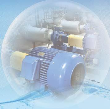
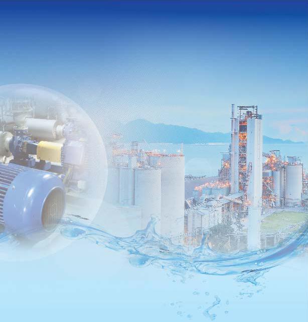
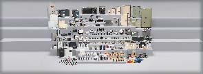
2 About us Switchgear Factory, Navi Mumbai Larsen & Toubro is a technology-driven company that infuses engineering with imagination. The Company offers a wide range of advanced solutions in the field of Engineering, Construction, Electrical & Automation, Machinery and Information Technology. L&T Switchgear, a part of the Electrical & Automation business, is India's largest manufacturer of low voltage switchgear, with the scale, sophistication and range to meet global benchmarks. With over seven decades of experience in this field, the Company today enjoys a leadership position in the Indian market with a growing international presence. Switchgear Factory, Ahmednagar It offers a complete range of products including powergear, controlgear, industrial automation, building electricals & automation, reactive power management, energy meters, and protective relays. These products conform to Indian and International Standards. Switchgear Factory, Vadodara


3

4
5 Motor Control solutions Larsen & Toubro India's largest manufacturer of low-voltage switchgear has always been in the forefront of motor control solutions. In the last few years, motor control solutions have seen a paradigm shift. With constantly evolving Industry requirements and technology advancement, there is a great demand for intelligent and automated solutions. Similarly, there is a greater demand for fuseless systems over fused systems. With our deep understanding of customer needs, we make sure that each and every need is met by our extensive range of switchgear products. Motor feeders are generally classified into two types: Fuse and Fuseless based on the type of short circuit protection devices used. Fuse systems incorporate fuses while fuseless systems have either molded case circuit breakers (MCCBs) or Motor Protection circuit breakers (MPCBs). The MCCBs are available for various current ratings and KA levels depending on the application. This offers you the flexibility of making the most apt selection as per your application. We have DM and d sine-m range of MCCBs which are exclusively designed for motor protection. MOG motor protection circuit breakers offer the advantage of having both overload and short circuit protection in a single compact unit. This solution is cost effective and ensures savings in panel space. The other major parts of any motor feeder are the contactors and relays. Contactors are the predominant switching devices with a high mechanical and electrical life. Overload relays offer protection against overload and single phasing and can be directly mounted onto the contactors. This makes the motor feeder extremely compact and modular. We offer an extensive range of MO and MNX contactors complemented by RTO and MN relays respectively. L&T also offers range of microcontroller based Motor protection relays to cater to various customer requirements. - a Mini Motor protection relay with inbuilt CT's is an economical solution for protection of Motors up to 0kW. provides Overload, Earth fault, Locked rotor, Phase failure, Phase sequence reversal, phase unbalance and under current protection. Our communicable Motor protection and control relay - MCOMP offers complete solution for Intelligent MCC's. Thus, L&T's extensive range of switchgear products caters to all your motor protection & control needs. Updated April 07


6 The following sections take you trough concepts of motor starting and motor protection solutions. In the further sections, - coordination selection charts are provided for making the right component selections. The main topics discussed in the following sections are: s of motor starting Selection of Protection Devices for Motor Feeders and Co-ordination Co-ordination for Energy Efficient Motors Co-ordination of Contactors & Overload Relays with MCBs selection charts Updated April 07
7 s of Motor Starting The most common method of motor starting is either Direct On Line (DOL) or Star - Delta. DOL starting is simple direct switching of a motor, however it leads to a high starting current. Star - Delta method is adopted in the motor feeders where high starting current is not acceptable. DOL Starting While DOL starting method is simple & most commonly used, care has to be taken while selecting the SCPD & relay. The possibility of high current peak & higher starting time during starting must be kept in mind. This is especially important while choosing MCCB & MPCB as SCPD as these device can sense current peaks & may trip. Hence it is recommended to select MCCB & MPCB with magnetic threshold of at least times of motor full load current for all standard motors & at least times of full load current for high efficiency motors. Star - Delta Starting Star Delta starting method is popularly used to reduce the motor starting current. For Star-Delta motor feeders, the motor winding is connected in star. When it reaches a certain speed the motor winding connection is changed to delta. Star Delta Starting can be of Two s Open Transition Open transition star delta starting is preferred in majority of the motor starting applications. In open transition starting there is a momentary loss of supply to the motor when the changeover from star to delta takes place. When the ON button is pressed, the star and main contactors get picked and the motor is connected in star configuration. As a result a reduced voltage (V / ) is applied across motor windings. The motor continues to L run in star connection for a period set in the star delta timer. After the time delay, star contactor drops off and delta contactor picks up causing the motor to get connected in delta. There is a pause time of the order 0-0 msec configured in every star delta timer. This is to ensure that delta contactor picks up only after star contactor has fully dropped to prevent the eventuality of a short circuit. When this changeover takes place, the motor sees a zero voltage across its terminals momentarily. During this time the rotating magnetic field across the stator reduces to zero. However the rotor is still spinning and has a magnetic field. This spinning action of the rotor causes a voltage to be induced in the stator determined by the speed of the rotor. This induced voltage across the stator is called the back EMF. When the motor is now connected in delta full line voltage appears across its terminals. The difference between the back emf and supply voltage causes a high transient current and corresponding high transient torque. Hence the motor experiences a jerk. The magnitude of the transient current depends on the phase relationship between the back EMF and supply voltage at the time of closure. This current peak may reach a value of about In and a corresponding mechanical jerk, which can be damaging to some critical processes. To avoid this closed transition starting is used in such cases. Updated April 07
8 Close Transition Close transition starting is used to reduce the high switching transients developed in the formerly discussed open transition starting and thus avoiding mechanical jerks. In close transition starter, a smooth changeover from star to delta takes place without the temporary loss of supply to motor. Thus even during the changeover from star to delta the motor continues to remain connected to the supply thus eliminating the switching transients. This is brought about by employing a fourth contactor along with a set of resistors. When the star contactor is opened, supply is maintained through the motor terminals via the resistors. The resistors are then shorted by the delta contactor when it closes. Let us understand the working with the help of a circuit diagram. Advantages and Disadvantages of Closed Transition starters: Advantages ) Operation is simple and rugged ) Transition Peak is reduced to. times full load current instead of times in open transition ) The sudden jerk the motor experiences in open transition, while closing the delta contactor is avoided Disadvantages ) More expensive ) Starter can be bulkier Thus open transition method is used for most of the applications owing to lesser cost. Closed transition starting is preferred only in critical applications where a smooth changeover from star to delta is required without the momentary jerk. R Y B N L L L S=star contactor D=delta contactor T= Transition contactor M=main contactor Fuse fuse relay D T M S Line Contactor Delta Contactor Star Contactor Resistance A B C Relay A B C U V W Ø MOTOR V U W Circuit diagram of a typical open transition Star Delta (SD) motor starter feeder. Circuit diagram of a typical close transition Star Delta (SD) motor starter feeder. Updated April 07
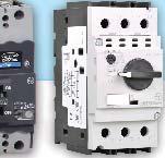
9 Selection of Protection Devices for Motor Feeder Introduction Motors are the backbone of any industry and their use is also rapidly increasing in commercial establishments. Protection of motor, hence becomes important to keep these processes functioning safely and without any interruption. The main purpose of motor protection system is to prevent excessive temperature built up in the windings because of over-current or short-circuit current. Following are the reasons for over-current: Overloading Single Phasing Voltage Imbalance Studies show that about 0% of the motor failures are due to electrical faults like over load, single phasing & short circuit. Hence it is extremely important to select effective motor protection devices to safeguard motors against any of the above faults, that will make motor windings to exceed safe working temperature. More importantly, the protection devices should be co-ordinated. Thermal Overload Relay Thermal overload relay should protect the motor against single phasing and overloading or locked rotor condition. At the same time, it should permit starting of the motor. In other words, it should withstand starting current for a duration equal to the starting time of the motor. IEC 07-- and IS/IEC 07-- has facilitated selection of a relay by defining a Trip Class'. Trip classes are mentioned in table. A relay of appropriate trip class can be selected by comparing 'locked rotor current withstand time' for the motor with maximum trip time. For example, for a motor with 'locked rotor current withstand time' of seconds, the relay should have trip time less than seconds at a current equal to locked rotor current. Hence, with reference to Table, a relay of 0A trip class will provide adequate protection. Table : Trip Class for Thermal Overload Relays Trip Class 0A * at 7. times the relay setting. Tripping Time, Tp, Seconds* <Tp 0 <Tp 0 <Tp 0 <Tp 0 Updated April 07
10 New generation of thermal overload relays incorporating double slide mechanism provide excellent protection against phase unbalance and phase failures even when motor is not running at full load. These relays don t see single phasing as overloading of others phases due to the double slide mechanism and hence work faster and effectively. Unbalanced voltages result in high unequal currents in stator windings and consequently higher temperature rise. Though balanced voltages are preferred, in some applications, voltage unbalance is unavoidable and some derating might be necessary. Where a motor is derated, selection of overload relay should take into account the derating factor. SCPD (FUSE / MCCB / MPCB) STARTER ( CONTACTOR + OVERLOAD RELAY) M MOTOR Fig. Single line diagram of a typical Direct-on-line (DOL) motor starter feeder. Short Circuit Protective Devices (SCPD) The current trends in Motor feeder protection are: Fused protection with S-D-F Fuseless protection with MCCB or MPCB While these devices are generally fast in clearing S.C. faults, they do take finite time to operate. By the time SCPD interrupts short circuit current, certain amount of fault energy passes through the protected circuit. All the downstream devices and cables in the protected circuit are subjected to stresses corresponding to this energy. The two important parameters which indicate the extent of stresses generated by short circuits are 'l t let through' and 'cut-off current'. These are explained in Fig.. 'l t let through' signifies thermal stresses. Cut-off current (Ic)' is indicative of electro-dynamic stresses that various devices and links / cables will have to withstand. Lower 'l t let through' and 'cut-off current indicate a more efficient SCPD and hence better short circuit protection. S-D-F, which incorporates H.R.C fuses, is the most efficient and popular in the industry. S-D-F, like conventional fuse-switch units, is capable of switching and protecting electrical circuits. In addition they have minimum let through energy & cut off current offering the most economical protection package. These are also suitable for isolating down stream equipment Updated April 07
11 Ip Current I t (let - through energy) "shaded area Ic T Total fault clearing time Time Fig. MCCB was primarily used for protection of distribution circuits. However, with the development of current limiting MCCBs, it has become possible to employ MCCBs in motor feeders also. With the availability of various accessories, MCCB as SCPD offers several advantages like low downtime & enhanced flexibility. However the let through energy & cut off current of MCCB is still higher compared to H.R.C. Fuses Motor protection circuit breakers (MPCBs) combine short circuit and overload protection in a single compact unit. MPCB can be used in two ways.firstly, it can be used for directly switching of a motor. This is very cost effective. However downside is that electrical life of MPCB is limited compared to that of a contactor. Moreover, a separate undervoltage protection is required. Alternately, MPCB can also be used along with a contactor. Since, MPCB combines thermal as well as short circuit protection, it will trip and interrupt even small overloads (which otherwise could be interrupted by a relay) and contactor will be used for switching the load Co-ordination of Thermal Overload Relay & SCPD What is Co-ordination? Co-ordination means matching the characteristics of SCPD and down stream equipment to ensure that the letthrough energy and peak cut-off current do not rise above the levels that the feeder can withstand. IEC / IS / EN specifications require that thermal overload relays and SCPD are co-ordinated to ensure that they operate satisfactorily under all load and fault conditions. Following two aspects need to be considered to achieve proper co-ordination: Discrimination between thermal overload relay and SCPD Adequacy of short circuit protection Discrimination To understand various considerations for proper co-ordination, time-current characteristics of thermal overload relay, H.R.C. fuse, MCCB with only instantaneous release and MPCB are superimposed on motor starting characteristics in Fig. b, b and b. Intersection of characteristics of thermal overload relay and Fuse / MCCB / MPCB is termed as 'cross-over point' and corresponding current as 'cross-over current' lco. Following points are to be ensured while selecting components to have properly co-ordinated motor protection: Contactor rating (AC-) should be more than or equal to motor full load current (if application is AC- duty) Thermal overload relay of appropriate 'Trip Class' is selected. Time current characteristics of the relay should remain above motor starting characteristics as shown in Fig. b and b Updated April 07 7
12 For fault currents lower than 'cross-over current lco', relay will respond faster than SCPD and hence contactor will interrupt the fault current. Fault currents higher than lco will be interrupted by SCPD. Hence, rating of contactor is so chosen that lco is less than rated breaking capacity of the contactor Relay and contactor should be able to withstand lco for a duration equal to trip time of the relay. IEC / IS / EN standards require that the contactor should be able to withstand at least current equal to times AC- rating ( times for ratings higher than 0A) for 0 seconds While using MCCB or MPCB, attention needs to be given to motor peak starting current. To avoid nuisance tripping of MCCB/MPCB during starting, instantaneous release shall be chosen as below: - For IE motors the starting current could be times full load current so instantaneous release shall be chosen as times the full load current of the motor - For IE motors the starting current could be times full load current so instantaneous release shall be chosen as times the full load current of the motor The corresponding co-ordination curves for MCCB and MPCB are shown in Fig. b and b. Similarly, while using MCCB/MPCB as a SCPD for Star-Delta starter, consideration needs to be given to peak current associated with change over from Star to Delta. Instantaneous release of MPCB is normally set at times the rating. Hence, possibility of nuisance tripping needs to be considered while using MPCB for protection for Star Delta starter feeder and Co-ordination in Motor Feeders Standards like IEC: 07-- and IS/IEC: 07-- specify motor protection requirements for selection of switching & protection device for motor feeders. Since there are more than one switching & protection device, it is necessary to co-ordinate the selection of components for a motor feeder. This is to be done keeping in mind the capabilities of the individual components. Such a co-ordinated selection will firstly, ensure safety to the user & secondly, provide the expected performance & life of the feeder components. Selection of components involves co-ordination of characteristics of various devices i.e. of the overload relay & of short circuit protection device of the motor feeder. As per the standard two types of co-ordination are permissible, and. co-ordination requires that under short-circuit conditions, the contactor or the starter shall cause no danger to persons or installation. The motor feeder may not be suitable for further service without repair and replacement of parts. co-ordination requires that under short-circuit conditions, the contactor or the starter shall cause no danger to persons or installation and shall be suitable for further use. However contact welding is recognized. Also the time-current characteristics of the over load protection device should not change. This in other words means safety, low down time and continued protection. Recommended combination needs to be proven through short-circuit tests at: Prospective current r Conditional short-circuit current q Updated April 07
13 Test at Prospective current r is done to verify the performance under fault conditions practically possible at the motor feeder end. These faults are normally associated with the motor and the associated feeder. Prospective current r is specified according to the rated operational current (Ie, AC-) of the feeder. If the motor feeder is not specified according to utilization category AC-, the prospective current r shall correspond to the highest rated operational current for any utilization category claimed by the manufacturer. The values are mentioned below: Table : Short Circuit Performance: 'r' Current Rated operational current Ie (AC-) A 0 Ie <= < Ie <= < Ie <= < Ie <= < Ie <= 0 0 < Ie <= < Ie <= < Ie Prospective current r ka 0 0 Subjected to agreement between manufacturer and user Test at Conditional short-circuit current Iq is carried out to verify the performance under system level faults. Iq is declared by the manufacturer. This is the maximum fault current that the feeder can withstand. Generally the declared value of Iq is 0 ka. Problems due to an improperly co-ordinated system An improperly co-ordinated system can lead to: High electro-dynamic force (magnetic force proportional to Ipeak) Nuisance tripping of / operation of SCPD under small overloads leading to reduced life of SCPD Nuisance tripping of SCPD during motor starting (DOL) Nuisance tripping of SCPD during transient conditions like open transition starting of a Star Delta starter Updated April 07
14 Typical DOL Motor Feeder with S-D-F S-D-F FUSE-LINK CONTACTOR RELAY MOTOR M Fig. a Co-ordination with S-D-F CONTACTOR BREAKING CAPACITY T I M E MOTOR CURRENT -In CURRENT CROSS OVER POINT OVERLOAD RELAY FUSE Fig. b 0 Updated April 07
15 Typical DOL Motor Feeder with MCCB MCCB CONTACTOR RELAY MOTOR M Fig. a Co-ordination with MCCB CONTACTOR BREAKING CAPACITY (>In) T I M E MOTOR CURRENT -In CURRENT In CROSS OVER POINT OVERLOAD RELAY MCCB Fig. b Updated April 07
16 Typical DOL Motor Feeder with MPCB MPCB CONTACTOR MOTOR M Fig. a Co-ordination with MPCB T I M E MOTOR CURRENT CROSS OVER POINT ( IN BUILT ) MPCB -In CURRENT In Fig. b Updated April 07

17 Co-ordination for Long Starting Time Application This note explains contactor selection for motors with long starting time. The note has been divided into three parts for easy understanding of the concepts involved. They are as follows:. Understanding Motor Inrush Current. Long Starting Time Applications. Contactor selection for motors with long starting time Understanding Motor Inrush Current (Stator current) A motor generally drives a load through some transmission system. During start, the motor draws a high starting current or inrush current. This current is about - times the motor rated current and can cause a significant voltage drop. This voltage fluctuation affects other devices connected to the same supply. Hence several other strategies are employed for starting motors to reduce its starting current; the most commonly employed being the Star Delta starting. The starting value of the current is independent of the load attached; however it must be sufficient to overcome the inertia of the motor load system. However, inertia of the load impacts the starting time of the motor as explained in the next part. As the motor accelerates and nears its rated speed, the current gradually reduces and settles down to a value equal to motor rated current or less depending on the actual load connected. The typical torque-speed characteristics of an induction motor are as given below: 00 % Torque 00 Locked Rotor or Breakaway Torque Breakdown or Peak Torque Rated Load Torque 00 Pull-up Torque Synchronous % Speed Speed/torque curve for a NEMA design B motor Updated April 07


18 Long Starting Time Applications The total time from rest till the motor draws its rated current is called the starting time. The starting time of the motor is a function of the load inertia, load speed and the starting torque developed by the motor. A high inertia load requires an extended time to reach full speed and hence the motor also draws high starting current for a long time. The motor starting time is specified by the manufacturer in the motor data sheet. Since motor starting time is also a function of applied voltage it differs for different starting methods. For example starting time of the motor with Direct-Online starting would be different than with Star-Delta starting. The starting line current in Star Delta configuration is one third of the starting current of the same motor in DOL configuration. However applied voltage and therefore starting torque also reduces, leading to higher starting time. Long Starting Time Applications are Generally those Applications in which the Motor Starting Time is around 0 to0 secs Typical applications involving motors with a high starting time are: Induced Draft Fans (ID Fans) Forced Draft Fans (FD Fans) ID and FD fans have a high inertia and hence motors required to drive them will have a long starting time. As a result the motor will draw high inrush current for an extended period of time. The high inrush current drawn by the motor at start is carried by the contactors that are used for switching. Since, this current flows for an extended period of time, the contactor needs to be selected judiciously. Guidelines for selection of contactor rating is as follows: Contactor Selection for Motors with Long Starting Time Contactors are selected based on their overload current withstand capability. Overload withstand capability is defined in IEC 07-- as given below: Rated Operational Current Ie AC Test Current Duration of Test 0 A x Ie max/ac- 0 sec 0 A x Ie max/ac-* 0 sec Updated April 07
19 It means that a contactor with rated operational current equal to or less than 0A can withstand times its rated AC operational current for a period of 0 seconds. This rating is also called as the 0 sec rating of the contactors. For Example: Let Rated operational current (AC Utilization category) of contactor = 00A Then the maximum current it can carry for a period of 0 sec = x I e = 00A Now let us look at an example, how to arrive at minimum AC Ratings of the Star, Main and Delta contactors. Motor Specifications Motor kw Rating: 0 kw Motor Full Load Line Current: 0A Motor Starting time in Star-Delta: sec Solution Delta contactor can be directly selected as per type chart specified by the contactor manufacturer. This is because delta contactor is connected only when the motor has reached near its rated speed and motor current has reduced to its full load value. For selection of Star contactor and Main contactor, the withstand current must be taken into consideration. A general schematic of Star-Delta starter is shown below: R Y B IfI N Fuse IfI / root Line Contactor Delta Contactor Star Contactor Relay V U W Ø MOTOR V W U Updated April 07
20 Starting current in a normal delta motor with DOL starting is around - times the motor full load current. However in Star-Delta starter motor starting current in star is reduced to / of this value. Typically starting current when using Star-Delta starting method is around. times motor full load current. Starting current (I s) =. x motor full load current =. x 0 = A Starting time (T s) = sec Therefore, (I ) x (T ) = x x (A) s s Now, Value (A) must be less than the contactor withstand capacity. i.e. Based on IEC 07--, Contactor Withstand Capacity = ( I e (AC) x 0 (B) It is required that, B > A Ie (AC) > A 0 Solving the above equation: Ie(AC). The contactor must be selected such that its rated AC- current Ie satisfies the above condition. Therefore in this case MNX 0 can be selected for Star & Main Contactor. In case of a 0 kw motor with normal starting time (<0 sec) the selection of contactors according to type charts is: Star Contactor: MNX 0 Main and Delta Contactor: MNX However for the same 0 kw motor with long starting time ( sec in this case) the contactor selection is: Star Contactor: MNX 0 Main Contactor: MNX 0 Delta Contactor: MNX. (C) This gives us the minimum rating of contactor required to withstand the starting current. We also need to evaluate the fuse rating for long starting time because the let through energy will increase.for a start time of -7 sec for the given motor rating (0KW) in star delta feeder, the fuse rating is A as per type coordination. For long starting time, fuse rating shall be chosen by referring by Time-current characteristic of fuse as shown below. The curve of the fuse shall lie above the crossing point of current and time. In this case the fuse rating comes out to be A. Updated April 07

21 HRC Fuse-links HN Time-Current Characteristics 0000 A 0 A 00 A A 0 A 00 A 0 A A 00 A 00 A 0 A 00 A 000 Pre-arcing Time (seconds) Symmetrical Current (A) The contactor suitable to withstand the let through energy of A fuse is: Star: MNX 0 Delta and Main: MNX Compare above contactor sizes with the contactor size derived in point no. (C) and select the higher contactor rating. Hence in case of 0KW motor, sec starting time with star delta starting method, the selection of contactor and fuse will be: Main Contactor: MNX 0 Star Contactor: MNX 0 Delta contactor: MNX Fuse: A Finally note that the Overload relay should be bypassed for this starting time, else it will trip during starting. Other alternative is to go with numerical motor protection relay where starting characteristics are programmable as required. Updated April 07 7
22 Co-ordination for Energy Efficient Motors Energy Efficient Motors and Corresponding Modifications in '' Chart Introduction In industry, the electric motor applications consume about 0% to 0% of the generated electrical energy worldwide. According to the findings of the International Energy Agency (IEA) Motor Workshop, electric motors with improved efficiency in combination with frequency converters can save up to 7% of the total worldwide electrical energy. One quarter to one third of these savings come from the improved efficiency of motor. As per motor regulation 0/00, the European Economic Area (EEA) has banned IE (low efficiency) motors with effect from June 0. Only energy efficient (IE and IE) motors are approved. However, the direct export of IE motors to countries outside the EEA is allowed by the act. Standard on motor efficiency IEC 00-0:00 defines the new efficiency classes for motors. The efficiency levels defined in IEC 00-0:00 are based on test methods for determining losses and efficiency specified in IEC 00--: 007 IEC 00-0:00 defines three IE (International Efficiency) classes of single-speed, three phase, 0Hz and 0 Hz, cage induction motors. IE: Standard efficiency (Efficiency level based on EFF) IE: High efficiency (Efficiency level based on EFF) IE: Premium efficiency (Efficiency level with losses about % to 0% lower compare to IE) The standard also introduces IE (Super Premium Efficiency), a future level above IE. However, the efficiency values for IE motors are not mentioned in the standard. The standard IS : 0 is in line with standard IEC 00-0: 00. The change in nomenclature from EFF to IE is yet to be implemented by Indian manufacturer fully. The standard IS : 0 has also mentioned the value of maximum full load current for all the efficiency classes. The efficiencies of the different classes as per IS: 0 are mentioned in following table: Updated April 07
23 Efficiency Comparison of Pole Motors Table Values of Performance Characteristics of Pole Energy Efficient Induction Motors (Class.,.,.,,.,. and 7.) IS : 0 Rated output Full Load Speed Full Load Current Breakaway Torque in Terms of Full Load Torque Breakaway Current in Terms of Full Load Current (Equal of Below) Nominal Efficiency Sr. No. Frame Size Min Max Min IE IE IE IE IE IE kw Rev/min A Percent Percent Percent Percent Percent Percent Percent () () () () () () (7) () () (0) () () S L L M S M M L M L L S M M S M S M ) M ) L As per manufacturer catalogue Notes:. Output to frame size relation is maintained in accordance with IS for all motors except those marked ) as, where in the frame size indicated is preferred size. The performance value given in this table for 0.7kW and 0.kW are under consideration and subject to review Updated April 07
24 Graphical Comparison of the Efficiency Classes Motors 7 Efficiency for 0 Hz [%] Power [kw] IE IE IE Efficiency and Losses The efficiency of a motor is defined as the ratio of output (mechanical) power to input (electrical) power. The efficiency of a motor is determined by the losses that can be reduced only by changes in motor design. Following are the typical motor losses:. Stator and Rotor I R Losses. Core Losses. Friction and Winding Losses. Additional Load Losses (PLL; It is that portion of losses in a machine not accounted for by the sum of friction and windage, stator I²R loss, rotor I²R loss and core loss) Given below is the typical summary of losses distribution in a motor. of Loss Stator I R Losses Rotor I R Losses Core Losses Friction and Windage Losses Additional Load Losses % Contribution in Total Loss Methods used to Achieve Higher Efficiencies. Reduction in Stator I R Losses: The Stator I R Loss is a function of stator current flowing through stator winding and the stator winding resistance. The resistance is given by following formula:.qn L R = 0 C R = Resistance in ohm q = No. of phases N = Turns in series per phase L = Mean length of turn in meter C = Total cross section of copper in all the slots (in all phases) in m 0 Updated April 07
25 The suitable selection of copper conductor size will reduce the resistance of the stator winding.. Reduction in Core Losses: The Core Losses consist of hysteresis and eddy current losses in the stator. Eddy current losses are generated by circulating current within the core steel laminations. It is given by following formula: Ke * f * t * B max Watts per m Wc = p Wc = Eddy current loss Ke = Proportionality constant f = Frequency t = Thickness Bmax = Maximum flux density in Weber per m p = Resistivity From the above formula, it is clear that the eddy current loss can be reduced by reducing the thickness of the core steel lamination suitably. The hysteresis losses are a function of flux density which can be reduced by suitable increase in the core length of stator and rotor. Impact of Reduction in Losses on Motor Current The increase in efficiency does not affect the full load current of the motor much. However, the starting current in case of high efficiency motor is more than that of standard motors. The equations for full load current and starting currents are mentioned below: V Stator current = Z jxm (R/S + jx) Z = + R + jx R/S + j (Xm + X) Where: R = Resistance, X = inductance, S = Slip of the motor, suffix : stator, suffix : rotor During starting period S = Istart = V R + jx As mentioned above, in high efficiency motors R is reduced to reduce the stator lose and improve the efficiency. This increases the starting current of the energy efficient motors as compare to standard motors. At full load S = 0 Ifl = At full load speed, Zfl >>>> (R+jX) V Zfl + R + jx Zfl = Where, jxm (R + jx) R + j (Xm + X) Updated April 07
26 Hence, the factor R being a smallest factor which contributes very less to the full load current, a small reduction in R does not affects the full load current much. Most of the manufacturers claim the FLC and starting current of their motors. The motor efficiency values as claimed by ABB are mentioned in Annex. As a result of the modifications to improve performance, the costs of energy-efficient motors are about % to 0% higher than those of standard motors. The higher cost is often being paid back rapidly in few years due to saving in operation of cost. Conclusion. As mentioned above, there is no change in FLC of the IE, IE & IE motors. The relay range required for overload protection will remain unchanged in case of energy efficient (IE) motors & (IE) motors with respect to standard (IE) motor. The starting current for energy efficient (IE/IE) motors is 7-7.7In (As per IS: 0). Where as the cross over point considered for existing back up fuse selection is between In to 0In. Hence there will be no change in type chart with fuse protection for energy efficient (IE / IE) motors with respect to standard (IE) motors. The starting current of IE/IE motors are more than IE motors which can result in nuisance tripping of the MCCB/MPCB. To avoid the nuisance tripping, there will be changes in selection of MCCB/MPCB with respect to existing type '' co-ordination selection chart of standard motors. In selection of the MCCB/MPCB, it is normal practice to take starting current times the full load current. For energy efficient motors the starting current should be taken as times the full load current. This will avoid the nuisance tripping of the circuit breaker. In star delta type of the motors starting, during change over from star to delta contactor high inrush current flows through the system. This current usually appears - 0 times the full load current. The current is given by formula mentioned below: [0 (voltage at star) + (voltage at delta)] x In (normal starting current) Ip = Ip = In approx Where, Ip = Peak current In = Line current Hence, for energy efficient motors as starting current is times FLC the peak current during star to delta change over will be times the full load current. However, this peak current lasts only for few milliseconds. Updated April 07
27 Co-ordination of Contactors & Overload Relays with MCBs and MPCBs s of MCBs Classes MCBs and their magnetic settings are as follows: Curve Magnetic Setting (Multiples of In) B - times C - 0 times D 0-0 times C MCBs are popularly used for Motor protection applications. Problem while using an MCB for Motor Protection Unlike a fuse unit, MCB is a peak sensing device. While providing SC protection to the motor it is imperative that the MCB does not trip on the starting transients of the motor. This care has to be taken while selecting the rating of the MCB. These transients are usually of the tune of times the full load current. Now suppose a C curve MCB is selected, in order to ensure it does not trip during the starting of the motor, times the motor full load current should be lesser than times the MCB's nominal current. For eg: For a motor having a full load current of A, * = 7A, A C curve MCB of rating = 7/ =., i.e. A will have to be selected Select a A AC- rated contactor and a relay having a range of - A Suppose a fault occurs and the motor starts drawing a current of 0A, the MCB will not trip as 0A is lesser than * = 7A. As a result, the overload relay will have to give a trip signal to the contactor to break this current. The IEC standard specifies the breaking capacity of a contactor to be times its AC- rating. 0A is greater than * = A as a result the contactor will get damaged. This problem can be rectified by de-rating the contactor. Updated April 07
28 The second more serious problem can be described by considering the below case: Consider a 0. hp motor with a full load current of 0.A. The initial starting current will be around.a. As in the earlier case a C curve MCB of A will have to be selected. With proper derating, a A Contactor is selected with a relay having rating of A. Now in this case, the crossover between the relay and the MCB will take place at * = 0A which is 0 times the upper limit of the relay. This will cause permanent damage to the relay. There is no solution to this problem as de-rating a relay is not possible. This is Co-ordination and not Suppose a D curve MCB is selected, then for the above case, a 7/0 = 7.A i.e. an A MCB will have to be selected. Now the MCB has to trip for currents between 0-0 times its nominal current. For the worst case in which the MCB trips at 0 times (i.e. 0A), for a fault current of 0A, the overload relay will have to give a tripping command to the MCB and there will be similar consequences as in the previous case. Thus in conclusion; while selecting an MCB for motor protection which may be a cost effective solution, one must be fully aware of the possible damages that might be caused to the contactor and overload relay. We recommend that if a customer wants fuseless protection for a feeder, MPCB be used. Caution while using MPCB in Star-Delta Motor Feeder In case of open transition star-delta starting (most common practice), it's an established fact that the transient current peaks during change-over from star to delta are in the order of times the line current (In). As the maximum magnetic threshold of a MPCB is In and as it is a current peak sensing device, such conditions will definitely lead to nuisance tripping of MPCBs during change-over from star to delta mode. Both the above facts i.e. times transient peak and nuisance tripping of MPCB have been verified through inhouse tests as well. Hence, to avoid nuisance tripping, it is technically correct to increase the MPCB rating for star/delta starting so that the ratio of instantaneous release setting to the motor full load current is at least. However, this will lead to loss in thermal overload protection offered by the MPCB (as the MPCB rating will be higher than the full load current of the motor). This aspect can be addressed by providing an additional thermal overload relay in the phase circuit. Summarizing If star-delta type chart with MPCB are offered without overload relay, it implies that the transient condition of star-delta changeover has been ignored then star-delta chart with MPCB should be with separate overload relay always. Updated April 07


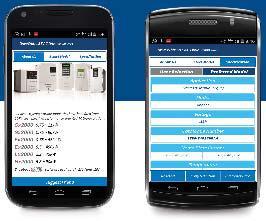
29 - coordination on mobile Updated April 07
30 - Selection Charts Feeder SCPD IE Fuse MCCB MPCB Fuse MCCB MPCB IE DOL MO + RTO Pg- Pg- Pg- Pg- Pg-0 Pg- SD MO + RTO Pg-0 Pg- Pg- Pg-0 Pg- Pg- DOL MNX + MN Pg-7 Pg- Pg- Pg-7 Pg- Pg- SD MNX + MN Pg- Pg- Pg-7 Pg- Pg- Pg- Note: ) The Full Load Current (FLC) indicated for -phase motors are of ' pole squirrel-cage Induction motors' at full load ) Contactors / S-D-Fs indicated are of the minimum ratings. Higher rating of contactors and S-D-Fs can be used ) Selection chart is for standard -phase, squirrel cage motor with average power factor and efficiency ) * : Only size '000' fuses to be used with FN 00 S-D-F ) # : Only size '00' fuses should be used with FN 0 S-D-F ) Selection is valid only for complete L&T combinations. Compliance to - co-ordination is not assured in case these combinations are changed to accommodate another brand / rating of product like S-D-F / Fuse etc. 7) All S-D-F ratings are AC-A as per IS/IEC 07-, IEC 07- & EN 07- ) Selection for motors with longer starting times can be made available on request ) All the MCCBs are Instantaneous type only 0) Efficiency of motors are as per IS : 0 IE motor: Standard motors IE motor: Energy efficient motors IE motor: Premium efficient motors Updated April 07
31 Fuse Protected DOL Starter Feeders : IE/ Motors TYPE '' Co-ordination, Iq=0/ ka at V, Ø, 0 Hz as per IS/IEC 07-- standard SCPD Relay FN/FNX SDF MNX MN Sr. No. Motor: Ø, V, 0 Hz hp kw In (A) Contactor Overload Relay Range (A) Nominal Backup Fuse Rating (A) S - D - F MN FN MN FN MN FN MN FN MN. -. FN MN. -. FN MN.0 -. FN.7..0 MN.0 -. FN.. MN - 0 FN 0.. MN. - FN.0 MN. - FN.7 MN. - 0 FN. MN FN.0 MNX MN - FN 0. MNX MN - 0 FN.. 7. MNX MN - 0 FN 7.0 MNX MN - FN.0 MNX MN 0 - FN 0.0 MNX 0 MN 0 - HN, 000* FN MNX 0 MN - 0 HN, 000* 0 FN MN 0-0 HN, 000* 0 FN MN - 7 HN, 000* 00 FN MNX 0 MN - 7 HN, 000 FN 0.0 MN - 0 HN, 000 FN 7.0 MN - 0 HN, 00# 0 FN MNX 0 MN 0-0 HN, 0 00 FN MNX 0 MN 0-0 HN, 0 00 FN MNX MN - HN, 0 FN MNX MN - HN, 0 FN MNX 0 MN - HN, FN 0.0 MNX 0 MN 0-00 HN, FN MNX 00 MN 0-00 HN, 00 FN MNX 00 MN 0-00 HN, 00 FN MNX 00 MN 70-0 HN, 00 FN MNX 00 MN 70-0 HN, 00 FN MNX 00 MN 70-0 HN, 00 FN MNX 0 MN 70-0 HN, 00 FN MNX 0 MN 70-0 HN, 0 FN 0.0 MNX 0 MN L 0-70 HN, 0 FN MNX 0 MN L 0-70 HN, 00 FN 00 Updated April 07 7
32 Fuse Protected DOL Starter Feeders : IE/ Motors TYPE '' Co-ordination, Iq=0/ ka at V, Ø, 0 Hz as per IS/IEC 07-- standard SCPD Relay FN/FNX SDF MO RTO Sr. No. Motor Ratings at Ø, V, 0 Hz hp kw In (A) Contactor Overload Relay Range (A) Nominal Backup Fuse Rating (A) S - D - F RTO FN RTO FN RTO FN RTO. - FN RTO. - FN RTO. -. FN RTO. -. FN.7..0 RTO. -. FN.. RTO FN 0.. RTO. -.7 FN.0 RTO. -.7 FN.7 RTO FN. RTO FN.0 MO RTO. -. FN 0. MO RTO FN.. 7. MO RTO FN 7.0 MO RTO 7 - FN.0 MO RTO 7 - FN 0.0 MO RTO - 7 HN 000* FN MO 0 RTO - 7 HN, 000* 0 FN MO 0 RTO - HN, 000* 0 FN MO 0 RTO 0-7 HN, 000* 00 FN MO 70 RTO 0-7 HN, 000 FN 0.0 RTO 7-0 HN, 000 FN 7.0 RTO 7-0 HN, 00# 0 FN MO 0 RTO 0 - HN, 0 00 FN MO 0 RTO 0 - HN, 0 00 FN MO RTO - 0 HN, 0 FN MO RTO - 0 HN, 0 FN MO RTO 0 - HN, FN 0.0 RTO 0 - HN, FN RTO 0 - HN, 00 FN MO 00 RTO 0 - HN, 00 FN MO 00 RTO - 7 HN, 00 FN 00 Updated April 07
33 Fuse Protected Star Delta Starter Feeders : IE/ Motors TYPE '' Co-ordination, Iq=0 ka at V, Ø, 0 Hz as per IS/IEC 07-- standard SCPD FN/FNX SDF MNX Relay MN Sr. No. Ratings at Ø, V, 0 Hz hp kw Current, In (A) Line Phase Star Delta Main Overload Relay Range (A) Nominal Backup Fuse Rating (A) S - D - F MN FN...7. MN. -. FN MN. -. FN...0 MN. -. FN... MN -. FN.0. MN - FN 7.7. MN - 0 FN.. MN - FN.0. MN. - FN MN FN MNX MNX MN - FN.0. MNX MNX MN - FN.0. MNX MNX MNX MN - FN MNX MNX MNX MN - 0 FN MNX MNX MNX MN - 0 FN MNX MNX MNX MN 0 - FN MNX MNX MNX MN 0 - HN, 000* FN MNX MN 0-0 HN, 000* 0 FN MN 0-0 HN, 000* 00 FN MN - 7 HN, 000* 00 FN MNX 0 MN - 0 HN, 00# 0 FN MNX 0 MN - 0 HN, 00# 0 FN MNX 0 MN - 0 HN, 00# 0 FN MNX 0 MNX 0 MN - 0 HN, 0 00 FN MNX 0 MNX 0 MN 0-0 HN, 0 FN MNX 0 MNX 0 MNX 0 MN 0-0 HN, 0 FN MNX 0 MNX MNX MN - HN, 0 FN MNX 0 MNX MNX MN - HN, FN MNX 0 MNX MNX MN - HN, FN MNX 0 MNX 00 MNX 00 MN - HN, 00 FN MNX 0 MNX 00 MNX 00 MN - HN, 00 FN MNX 00 MNX 00 MNX 00 MN 0-00 HN, 00 FN MNX 00 MNX 00 MNX 00 MN 0-00 HN, 00 FN MNX 00 MNX 0 MNX 0 MN 70-0 HN, 0 FN MNX 00 MNX 0 MNX 0 MN 70-0 HN, 0 FN MNX 00 MNX 0 MNX 0 MN 70-0 HN, 0 FN MNX 00 MNX 0 MNX 0 MN 70-0 HN, 0 FN MNX 0 MNX 0 MNX 0 MN 70-0 HN, 00 FN 00 Updated April 07
34 Fuse Protected Star Delta Starter Feeders : IE/ Motors TYPE '' Co-ordination, Iq=0 ka at V, Ø, 0 Hz as per IS/IEC 07-- standard SCPD FN/FNX SDF MO Relay RTO Sr. No. Ratings at Ø, V, 0 Hz hp kw Current, In (A) Line Phase Star Line Delta Overload Relay Range (A) Nominal Backup Fuse Rating (A) S - D - F RTO. -.0 FN...7. RTO. -.0 FN RTO. -.0 FN...0 RTO. -. FN... RTO. -. FN.0. RTO. -. FN 7.7. RTO FN.. RTO. -.7 FN.0. RTO. -.7 FN RTO FN MO MO RTO. -. FN.0. MO MO RTO. -. FN.0. MO MO MO RTO. -. FN MO MO MO RTO FN MO MO MO RTO 7-0 FN MO MO MO RTO 7 - FN MO MO MO RTO - 7 HN, 000 * FN MO MO 0 MO 0 RTO - HN, 000 * 0 FN MO 0 MO 0 RTO 0-7 HN, 000* 00 FN MO 0 MO 0 RTO 0-7 HN, 000* 00 FN MO 0 MO 0 MO 0 RTO 7-0 HN, 00# 0 FN MO 0 RTO 7-0 HN, 00# 0 FN MO 0 RTO 7-0 HN, 00# 0 FN MO 0 MO 0 RTO 7-0 HN, 0 00 FN MO 0 MO 0 RTO 0 - HN, 0 FN MO 0 MO 0 MO 0 RTO 0- HN, 0 FN MO 0 MO MO RTO 0 - HN, 0 FN MO 0 MO MO RTO -0 HN, FN MO 0 MO MO RTO - 0 HN, FN MO RTO - 0 HN, 00 FN MO RTO 0 - HN, 00 FN MO 00 MO 00 RTO 0 - HN, 00 FN MO 00 MO 00 MO 00 RTO 0 - HN, 00 FN 0 0 Updated April 07
35 Fuseless Protection for DOL Starter Feeders : IE Motors TYPE '' Co-ordination, Iq=0 ka at V, Ø, 0 Hz as per IS/IEC 07-- standard SCPD DN MCCB MNX Relay MN Sr. No. Motor: Ø, V, 0 Hz hp kw FLC, In (A) Contactor Overload Relay Range (A) MCCB Rating (A) MNX DN-0M 00 0 MNX 0 0 DN-0M 7 MNX 0 0 DN-0M MNX MN 0 0 DN-0M MNX MN 0 0 DN-0M MNX MN DN-0M MNX 0 MN DN-00M MNX 0 MN 0 00 DN-00M 0 0 MNX 00 MN 0 00 DN-00M MNX 00 MN 0 00 DN-00M MNX 00 MN 0 00 DN-00M MNX 00 MN 70 0 DN-0M MNX 00 MN 70 0 DN-0M MNX 0 MN 70 0 DN-0M MNX 0 MN 70 0 DN-0M 0 Updated April 07
36 Fuseless Protection for DOL Starter Feeders : IE Motors TYPE '' Co-ordination, Iq=0 ka at V, Ø, 0 Hz as per IS/IEC 07-- standard SCPD DN MCCB MO Relay RTO Sr. No. Motor Ratings at Ø, V, 0 Hz Overload Relay MCCB hp kw FLC, In (A) Range (A) Rating (A) RTO- RTO- 0 0 RTO RTO MO 0 RTO MO 0 RTO MO 0 RTO RTO- 0 7 DN-0M 00 0 RTO- 7 0 DN-0M 7 MO 0 RTO- 7 0 DN-0M MO RTO- 0 DN-0M MO RTO- 0 DN-0M MO RTO- 0 DN-0M RTO- 0 DN-00M RTO- 0 DN-00M 0 0 MO 00 RTO- 0 DN-00M MO 00 RTO- 0 DN-00M MO 00 RTO- 0 DN-00M 00 Updated April 07
37 Fuseless Protection for DOL Starter Feeders : IE Motors TYPE '' Co-ordination, Iq=0 ka at V, Ø, 0 Hz as per IS/IEC 07-- standard SCPD MOG MPCB MNX Sr. No. Motor: Ø, V, 0 Hz hp kw FLC, In (A) Contactor MPCB Rating (A) MOG-S/MOG-H MOG-S/MOG-H MOG-S/MOG-H MOG-S/MOG-H MOG-S/MOG-H MOG-S/MOG-H MNX MOG-S/MOG-H MNX MOG-S/MOG-H. -.. MNX MOG-S/MOG-H MNX MOG-S/MOG-H -..0 MNX MOG-S/MOG-H -..7 MNX MOG-S/MOG-H MNX MOG-S/MOG-H MNX MOG-S/MOG-H - 0. MNX MOG-S/MOG-H MNX MOG-S/MOG-H MNX 0 MOG-S/MOG-H -.0 MOG-S/MOG-H MOG-S/MOG-H MOG-H MOG-H MNX 0 MOG-H - Updated April 07
38 Fuseless Protection for DOL Starter Feeders : IE Motors TYPE '' Co-ordination, Iq=0 ka at V, Ø, 0 Hz as per IS/IEC 07-- standard SCPD MOG MPCB MO Sr. No. Motor Ratings at Ø, V, 0 Hz hp kw FLC in (A) MPCB Rating (A) MOG-S / MOG-H MOG-S / MOG-H MOG-S / MOG-H MOG-S / MOG-H MOG-S / MOG-H MOG-S / MOG-H MO MOG-S / MOG-H MO MOG-S / MOG-H. -.. MO MOG-S / MOG-H MO MOG-S / MOG-H -..0 MO MOG-S / MOG-H -..7 MO MOG-S / MOG-H MO MOG-S / MOG-H MO MOG-S / MOG-H - 0. MO MOG-S / MOG-H MO MOG-S / MOG-H MO MOG-S / MOG-H -.0 MO MOG-S / MOG-H MO MOG-S / MOG-H MOG-H MOG-H MO 0 MOG-H - Updated April 07
39 Fuseless Protection For Star Delta Starter Feeders : IE Motors TYPE '' Co-ordination, Iq=0 ka at V, Ø, 0 Hz as per IS/IEC 07-- standard SCPD DN MCCB MNX Relay MN Sr. No. Ratings at Ø, V, 0 Hz hp kw Current, In (A) Line Phase Star Delta Main Overload Relay Range (A) MCCB Rating (A) 0.7. MNX MNX MNX MNX.7... MNX. MNX 7.7. MNX.. MNX. MNX MNX MNX 0. MNX 0. MNX MNX. 0. MNX 0 MNX MNX 0 MNX MN. DN-0M MN. DN-0M 0. MN DN-0M MN DN-0M MNX 0 MNX 0 MNX 0 MN 0 00 DN-0M MNX 0 MNX 0 MN 0 00 DN-00M MNX 0 MNX 0 MN 0 0 DN-00M MNX 0 MNX 0 MNX 0 MN 0 0 DN-00M MNX 0 MNX 0 MNX 0 MN 0 0 DN-00M MNX 0 MNX 00 MNX 00 MN 0 0 DN-0M MNX MNX 00 MNX 00 MN DN-0M MNX MNX 00 MNX 00 MN DN-0M MNX MNX 00 MNX 00 MN DN-0M MNX MNX 00 MNX 00 MN DN-0M 0 Updated April 07
40 Fuseless Protection For Star Delta Starter Feeders : IE Motors TYPE '' Co-ordination, Iq=0 ka at V, Ø, 0 Hz as per IS/IEC 07-- standard SCPD DN MCCB MO Relay RTO Sr. No. Motor Ratings at Ø, V, 0 Hz Current, In (A) hp kw Star Line Phase Delta Main Overload Relay Range (A) MCCB Rating (In) 0.7. MO MO MO MO.7... MO. MO 7.7. MO.. MO. MO MO MO RTO MO RTO MO RTO MO RTO-. 0. MO MO 70 MO 70 RTO MO 70 MO 70 RTO RTO- DN-0M RTO- 7 DN-0M 0. MO 70 RTO- 7 DN-0M MO 70 RTO- 7 DN-0M MO 0 MO 0 MO 0 RTO- 7 DN-0M RTO- 7 DN-00M RTO- 7 0 DN-00M MO 0 RTO- 0 DN-00M MO 0 RTO- 0 DN-00M 00 0 MO 0 MO 00 MO 00 RTO- 0 DN-0M MO MO 00 MO 00 RTO- 0 DN-0M 00 Updated April 07
41 Fuseless Protection For Star Delta Starter Feeders : IE Motors TYPE '' Co-ordination, Iq=0 ka at V, Ø, 0 Hz as per IS/IEC 07-- standard SCPD MOG MPCB MNX Relay MN Sr. No. Ratings at Ø, V, 0 Hz hp kw Current, In (A) Line Phase Star Delta Main Overload Relay Range (A) MPCB Rating (A) MN MOG-HM MN 0. - MOG-HM MN MOG-HM MNX MNX MN MOG-HM...7. MNX MNX MN. -. MOG-HM MNX MNX MN. -. MOG-HM MNX MNX MN.0 -. MOG-HM.... MNX MNX MN.0 -. MOG-HM 0.0. MNX MNX MN MOG-HM MNX MNX MN MOG-HM.. MNX MNX MN. - MOG-HM.0. MNX MNX MN -0 MOG-HM 0.. MNX MNX 0 MNX 0 MN -0 MOG-HM MNX - MOG-HM.0. MNX - MOG-HM.0. MNX - MOG-HM MNX - MOG-HM MNX 0 - MOG-HM MNX MNX 0 MNX 0 Mn 0 - MOG-HM Updated April 07 7
42 Fuseless Protection For Star Delta Starter Feeders : IE Motors TYPE '' Co-ordination, Iq=0 ka at V, Ø, 0 Hz as per IS/IEC 07-- standard SCPD MOG MPCB MO Relay RTO Sr. No. Motor Ratings at Ø, V, 0 Hz Overload Relay MPCB hp kw I line (A) I phase (A) Star Delta Main Range (A) Rating (A) RTO MOG-HM RTO MOG-HM RTO MOG-HM MO MO RTO. - MOG-HM...7. MO MO RTO. - MOG-HM MO MO RTO. - MOG-HM MO MO RTO. -. MOG-HM.... MO MO RTO. -. MOG-HM 0.0. MO MO RTO. -. MOG-HM MO MO RTO. -. MOG-HM.. MO MO RTO. -. MOG-HM.0. MO MO RTO. -.7 MOG-HM 0.. MO MO MO RTO MOG-HM MO MO MO RTO. -. MOG-HM.0. MO MO MO RTO. -. MOG-HM.0. MO RTO 0. - MOG-HM MO MO 0 MO 0 RTO - MOG-HM MO MO 0 MO 0 RTO - MOG-HM MO MO 70 MO 70 RTO 0 - MOG-HM Updated April 07
43 Fuseless Protection for DOL Starter Feeders : IE Motors TYPE '' Co-ordination, Iq=0 ka at V, Ø, 0 Hz as per IS/IEC 07-- standard SCPD DN MCCB MNX Relay MN Sr. No. Motor: Ø, V, 0 Hz hp kw FLC, In (A) Contactor Overload Relay Range (A) MCCB Rating (A) MNX DN-0M 0 MNX 0 0 DN-0M 0 7 MNX 0 0 DN-0M MNX MN 0 0 DN-0M MNX MN 0 0 DN-0M MNX 0 MN DN-00M MNX 0 MN DN-00M MNX 00 MN 0 00 DN-00M 00 0 MNX 00 MN 0 00 DN-00M MNX 00 MN 0 00 DN-00M MNX 00 MN 0 00 DN-0M MNX 00 MN 70 0 DN-0M MNX 0 MN 70 0 DN-0M MNX 0 Mn 70 0 DN-0M 0 Updated April 07
44 Fuseless Protection for DOL Starter Feeders : IE Motors TYPE '' Co-ordination, Iq=0 ka at V, Ø, 0 Hz as per IS/IEC 07-- standard SCPD DN MCCB MO Relay RTO Sr. No. Motor Ratings at Ø, V, 0 Hz hp kw FLC, In (A) Overload Relay Range (A) MCCB Rating (A) RTO- RTO- 0 0 RTO MO 0 RTO MO 0 RTO MO 0 RTO MO 0 RTO MO 0 RTO- 0 7 DN-0M 0 MO 0 RTO- 7 0 DN-0M 0 7 MO 0 RTO- 7 0 DN-0M MO RTO- 0 DN-0M MO RTO- 0 DN-0M RTO- 0 DN-00M RTO- 0 DN-00M MO 00 RTO- 0 DN-00M 00 0 MO 00 RTO- 0 DN-00M MO 00 RTO- 0 DN-00M 00 0 Updated April 07
45 Fuseless Protection for DOL Starter Feeders : IE Motors TYPE '' Co-ordination, Iq=0 ka at V, Ø, 0 Hz as per IS/IEC 07-- standard SCPD MOG MPCB MNX Sr. No. Motor: Ø, V, 0 Hz hp kw FLC, In (A) Contactor MPCB Rating (A) MOG-S/MOG-H MOG-S/MOG-H MOG-S/MOG-H MOG-S/MOG-H MOG-S/MOG-H MOG-S/MOG-H MNX MOG-S/MOG-H MNX MOG-S/MOG-H. -.. MNX MOG-S/MOG-H MNX MOG-S/MOG-H -..0 MNX MOG-S/MOG-H -..7 MNX MOG-S/MOG-H MNX MOG-S/MOG-H MNX MOG-S/MOG-H - 0. MNX MOG-S/MOG-H -.0 MNX 0 MOG-S/MOG-H MOG-S/MOG-H MOG-H MOG-H MOG-H - 0 Updated April 07
46 Fuseless Protection for DOL Starter Feeders : IE Motors TYPE '' Co-ordination, Iq=0 ka at V, Ø, 0 Hz as per IS/IEC 07-- standard SCPD MOG MPCB MO Sr. No. Motor Ratings at Ø, V, 0 Hz hp kw FLC, In (A) MPCB Rating (A) MOG-S / MOG-H MOG- S / MOG-H MOG-S / MOG-H MOG- S / MOG-H MOG-S / MOG-H MOG- S / MOG-H MO MOG-S / MOG-H MO MOG- S / MOG-H. -.. MO MOG-S / MOG-H MO MOG- S / MOG-H -..0 MO MOG-S / MOG-H -..7 MO MOG- S / MOG-H MO MOG-S / MOG-H MO MOG- S / MOG-H - 0. MO MOG- S / MOG-H MO MOG- S / MOG-H MO MOG- S / MOG-H MOG - H MOG - H MO 0 MOG - H - 0 Updated April 07
47 Fuseless Protection For Star Delta Starter Feeders : IE Motors TYPE '' Co-ordination, Iq=0 ka at V, Ø, 0 Hz as per IS/IEC 07-- standard SCPD DN MCCB MNX Relay MN Sr. No. Ratings at Ø, V, 0 Hz hp kw Current, In (A) Line Phase Star Delta Main Overload Relay Range (A) MCCB Rating (A) 0.7. MNX MNX MNX MNX.7... MNX. MNX 7.7. MNX.. MNX MN.. MNX MN MNX MN MNX 0. MNX 0. MNX 0.7 MNX MNX 0 MNX MNX 0 MNX MNX 0 MNX MN. DN-0M 0 7. MN. DN-0M 0 0. MN DN-0M MN DN-0M MNX 0 MNX 0 MNX 0 MN 0 00 DN-00M MNX 0 MNX 0 MN 0 00 DN-00M MNX 0 MNX 0 MN 0 00 DN-00M MNX 0 MNX 0 MNX 0 MN 0 0 DN-00M MNX 0 MNX 00 MNX 00 MN 0 0 DN-0M 00 0 MNX 0 MNX 00 MNX 00 MN 0 0 DN-0M MNX MNX 00 MNX 00 MN DN-0M MNX MNX 00 MNX 00 MN DN-0M MNX MNX 00 MNX 00 Mn DN-0M 0 Updated April 07
48 Fuseless Protection For Star Delta Starter Feeders : IE Motors TYPE '' Co-ordination, Iq=0 ka at V, Ø, 0 Hz as per IS/IEC 07-- standard SCPD DN MCCB MO Relay RTO Sr. No. Motor Ratings at Ø, V, 0 Hz Current, In (A) hp kw Star Line Phase Delta Main Overload Relay Range (A) MCCB Rating (In) 0.7. MO MO MO MO.7... MO. MO 7.7. MO.. MO. MO MO MO RTO MO RTO MO MO 70 MO 70 RTO MO MO 70 MO 70 RTO MO 70 MO 70 RTO MO 70 MO 70 RTO RTO- DN-0M 0 7. RTO- 7 DN-0M 0 0. MO 70 RTO- 7 DN-0M MO 70 RTO- 7 DN-0M MO 0 RTO- 7 DN-00M RTO- 7 DN-00M RTO- 7 0 DN-00M MO 0 RTO- 0 DN-00M MO 0 MO 00 MO 00 RTO- 0 DN-0M 00 0 MO 0 MO 00 MO 00 RTO- 0 DN-0M MO MO 00 MO 00 RTO- 0 DN-0M 00 Updated April 07
49 Fuseless Protection For Star Delta Starter Feeders : IE Motors TYPE '' Co-ordination, Iq=0 ka at V, Ø, 0 Hz as per IS/IEC 07-- standard SCPD MOG MPCB MNX Relay MN Sr. No. Ratings at Ø, V, 0 Hz hp kw Current, In (A) Line Phase Star Delta Main Overload Relay Range (A) MPCB Rating (A) MN MOG-HM MN 0. - MOG-HM MN MOG-HM MNX MNX MN MOG-HM MNX MNX MN. -. MOG-HM MNX MNX MN. -. MOG-HM MNX MNX MN.0 -. MOG-HM.... MNX MNX MN.0 -. MOG-HM MNX MNX MN MOG-HM MNX MNX MN MOG-HM.0.. MNX MNX MN. - MOG-HM.0.0. MNX MNX MN -0 MOG-HM MNX MNX 0 MNX 0 MN -0 MOG-HM MNX - MOG-HM.0.0. MNX - MOG-HM.0.0. MNX - MOG-HM MNX - MOG-HM MNX MNX 0 MNX MOG-HM MNX MNX 0 MNX 0 Mn 0 - MOG-HM.0 Updated April 07
50 Fuseless Protection For Star Delta Starter Feeders : IE Motors TYPE '' Co-ordination, Iq=0 ka at V, Ø, 0 Hz as per IS/IEC 07-- standard SCPD MOG MPCB MO Relay RTO Sr. No. Motor Ratings at Ø, V, 0 Hz Overload Relay MPCB hp kw I line (A) I phase (A) Star Delta Main Range (A) Rating (A) RTO MOG-HM RTO MOG-HM RTO MOG-HM MO MO RTO. - MOG-HM...7. MO MO RTO. - MOG-HM MO MO RTO. - MOG-HM MO MO RTO. -. MOG-HM.... MO MO RTO. -. MOG-HM 0.0. MO MO RTO. -. MOG-HM MO MO RTO. -. MOG-HM.. MO MO RTO. -. MOG-HM.0. MO MO RTO. -.7 MOG-HM MO MO MO RTO MOG-HM MO MO MO RTO. -. MOG-HM.0. MO RTO 0. - MOG-HM.0. MO RTO 0. - MOG-HM MO MO 0 MO 0 RTO - MOG-HM MO MO 70 MO 70 RTO - MOG-HM MO MO 70 MO 70 RTO 0 - MOG-HM Updated April 07


51 Aimed at maximizing productivity, conserving energy, minimizing costs and enhancing safety, our Electrical & Automation training programmes have benefitted over.77 Lakh professionals in the last 0 years. These training programmes are highly beneficial as they provide right exposure So gain the advantage and go the extra mile with: courses on contemporary topics Courses applicable to all switchgear brands Training Centers in Pune, Lucknow, Coonoor, Vadodara, Delhi & Kolkata Blend of theory and practical experience The typical training programmes cover: Low Voltage & Medium Voltage Switchgear Switchboard Electrical Design AC Drives & Building Management Solutions Protective Relays, Earthing, Reactive Power Management & Harmonics Energy Conservation & Management Please contact any of the training centres for participation and detailed training programme schedule. Pune Larsen & Toubro Limited Switchgear Training Centre, T-/7, MIDC Bhosari, Pune - 0 Tel: / 7 0 Fax: stc-pune@lntebg.com Lucknow Larsen & Toubro Limited Switchgear Training Centre, C - & 7, UPSIDC P. O. Sarojininagar, Lucknow - 00 Tel: / 7 Fax: stc-lucknow@lntebg.com Coonoor Larsen & Toubro Limited Switchgear Training Centre, Ooty-Coonoor Main Road Yellanahalli P.O., The Nilgiris - Tel. : Fax : stc-coonoor@lntebg.com Vadodara Larsen & Toubro Limited Switchgear Training Centre Behind L&T Knowledge City, Near Village Ankhol, Vadodara - 00 Tel: stc-vadodara@lntebg.com Delhi Larsen & Toubro Ltd Switchgear Training Centre, Shivaji Marg, Near Motinagar Metro Station, New Delhi 00 Tel: 0 / /00 Fax: stc-delhi@lntebg.com Kolkata Larsen & Toubro Limited Switchgear Training Centre th Floor, B, Shakespeare Sarani, Kolkata Tel: stc-kolkata@lntebg.com
Motor Protection Circuit Breakers
 Motor Protection Circuit Breakers About us Larsen & Toubro is a technologydriven USD 9.8 billion company that infuses engineering with imagination. The Company offers a wide range of advanced solutions
Direct On Line (DOL) Motor Starter. Direct Online Motor Starter
 Motor Starter. Direct Online Motor Starter") Direct On Line (DOL) Motor Starter Direct Online Motor Starter Different starting methods are employed for starting induction motors because Induction Motor draws more starting current during starting.
Direct On Line (DOL) Motor Starter Direct Online Motor Starter Different starting methods are employed for starting induction motors because Induction Motor draws more starting current during starting.
Moulded Case Circuit Breakers
 Moulded Case Circuit Breakers DU Series About us Larsen & Toubro is a technologydriven company that infuses engineering with imagination. The Company offers a wide range of advanced solutions in the field
Types of Motor Starters There are several types of motor starters. However, the two most basic types of these electrical devices are:
 Introduction Motor starters are one of the major inventions for motor control applications. As the name suggests, a starter is an electrical device which controls the electrical power for starting a motor.
Technical Section: Miniature Circuit Breakers
 MCBs and Accessories Data. Calibration With CBI Hydraulic- Magnetic Miniature Circuit Breakers, there is no effect on the fixed trip point at ambient temperature ranges from -5 C to +60 C. 2. Products
About us. Switchgear Factory, Mumbai
 About us Larsen & Toubro is a technologydriven USD 8.5 billion company that infuses engineering with imagination. The Company offers a wide range of advanced solutions in the field of Engineering, Construction,
Induction Motor Control
 Induction Motor Control A much misunderstood yet vitally important facet of electrical engineering. The Induction Motor A very major consumer of electrical energy in industry today. The major source of
Question Number: 1. (a)
") Session: Summer 2008 Page: 1of 8 Question Number: 1 (a) A single winding machine cannot generate starting torque. During starting the switch connects the starting winding via the capacitor. The capacitor
Session: Summer 2008 Page: 1of 8 Question Number: 1 (a) A single winding machine cannot generate starting torque. During starting the switch connects the starting winding via the capacitor. The capacitor
Application Description
 -14 Type, Intelligent Technologies (IT.) Soft Starters February 2007 Contents Description Page Type, Intelligent Technologies (IT.) Soft Starters Product Description....... -14 Application Description....
Principles of iers (intelligent
 Principles of iers (intelligent Energy Recovery System) Chapter 4 Table of Contents............... 4 1 Principles of the iers....................................... 4 2 Enabling Intelligent Energy Recovery
Issued by : Switchgear Contracts Division LARSEN & TOUBRO LIMITED Powai Works, Mumbai October December 1996
 Issued by : Switchgear Contracts Division LARSEN & TOUBRO LIMITED Powai Works, Mumbai 400 072. October December 1996 Prospect/ Retrospect IS/IEC Specification In the previous three issues of L&T Current
EEE3441 Electrical Machines Department of Electrical Engineering. Lecture. Introduction to Electrical Machines
 Department of Electrical Engineering Lecture Introduction to Electrical Machines 1 In this Lecture Induction motors and synchronous machines are introduced Production of rotating magnetic field Three-phase
3.2. Current Limiting Fuses. Contents
 .2 Contents Description Current Limiting Applications................. Voltage Rating.......................... Interrupting Rating....................... Continuous Current Rating................ Fuse
10. Starting Method for Induction Motors
 10. Starting Method for Induction Motors A 3-phase induction motor is theoretically self starting. The stator of an induction motor consists of 3-phase windings, which when connected to a 3-phase supply
2.1 Warnings & Agency Approvals Electrical Connections - Specifications Standard Wiring Configurations...2 4
 CHAPTER ELECTRICAL 2 INSTALLATION Contents of this Chapter... 2.1 Warnings & Agency Approvals..................2 2 2.1.1 Isolation..............................................2 2 2.1.2 Electrical Power
Characteristics of LV circuit breakers Releases, tripping curves, and limitation
 Characteristics of LV circuit breakers Releases, tripping curves, and limitation Make, Withstand & Break Currents A circuit breaker is both a circuit-breaking device that can make, withstand and break
About us. Switchgear Factory, Mumbai
 Wires & Cables About us Larsen & Toubro is a technologydriven USD 9.8 billion company that infuses engineering with imagination. The Company offers a wide range of advanced solutions in the field of Engineering,
MAGNETIC MOTOR STARTERS
 Chapter 6 MAGNETIC MOTOR STARTERS 1 The basic use for the magnetic contactor is for switching power in resistance heating elements, lighting, magnetic brakes, or heavy industrial solenoids. Contactors
(i) in paragraph 9, for sub-paragraph (i) the following shall be substituted, namely:-
 in paragraph 9, for sub-paragraph (i) the following shall be substituted, namely:-") Revision 3 Date: 28/01/2016 Amendment to Schedule 6 for Induction Motor In the said schedule, (i) in paragraph 9, for sub-paragraph (i) the following shall be substituted, namely:- Effective from 1 st
Revision 3 Date: 28/01/2016 Amendment to Schedule 6 for Induction Motor In the said schedule, (i) in paragraph 9, for sub-paragraph (i) the following shall be substituted, namely:- Effective from 1 st
Application Note: Protection of Medium-Power Motors With SIPROTEC Compact 7SK80
 Application Note: Protection of Medium-Power Motors With SIPROTEC Compact 7SK80 Motor settings using the SIPROTEC Compact motor protection relay 7SK80 is explained below. Information is given on how to
Paramount HRC Cartridge
 Paramount HRC Cartridge Eaton MEM HRC fuselinks are manufactured to exacting standards using precision assembly methods and undergo rigorous quality checking before dispatch including resistance testing
NEW. Moulded Case Circuit Breakers New DU Series 20 A to 250 A
 NEW Moulded Case Circuit Breakers New DU Series 0 A to 50 A About us Larsen & Toubro is a technology-driven USD 7 billion company that infuses engineering with imagination. The Company offers a wide range
RVS-AX Instruction Manual
 RVS-AX Analog Soft Starter 8-170A, 220-600V Instruction Manual Ver. 10/11/2009 2 Table of Content RVS-AX Instruction Manual 1. TABLE OF CONTENT 1. Table of Content...2 2. Safety & Warnings...3 2.1 Safety...3
Hybrid Motor Technology to Achieve Efficiency Levels Beyond NEMA Premium
 Hybrid Motor Technology to Achieve Efficiency Levels Beyond NEMA Premium Richard R. Schaefer, Baldor Electric Company ABSTRACT This paper will discuss the latest advances in AC motor design that combines
ESO 210 Introduction to Electrical Engineering
 ESO 210 Introduction to Electrical Engineering Lectures-37 Polyphase (3-phase) Induction Motor 2 Determination of Induction Machine Parameters Three tests are needed to determine the parameters in an induction
DX 3 MCBs. Choice of DX 3 MCBs for capacitor banks. Technical data
 Specifications IS/IEC 60898-1 2002 Number of poles SP, SPN, DP, TP, TPN, FP Characteristics C & D Curve Breaking capacity 10 ka 0.5 A to 63 A as per IS/IEC 60898-1 2002 16 ka for 0.5 A to 25 A as per IEC
EXPERIMENT 2 THREE PHASE INDUCTION MOTOR, PART 1
 University f Jordan School of Engineering Department of Mechatronics Engineering Electrical Machines Lab Eng. Osama Fuad Eng. Nazmi Ashour EXPERIMENT 2 THREE PHASE INDUCTION MOTOR, PART 1 OBJECTIVES To
AGN Unbalanced Loads
 Application Guidance Notes: Technical Information from Cummins Generator Technologies AGN 017 - Unbalanced Loads There will inevitably be some applications where a Generating Set is supplying power to
Installation Manual for DC Injection Brake Units
 Power Drive Services INJ Series DC brake modules PDS 11-30-100A Page 1 of 17 Issue 15 Contents. 1. Safety. 2. Installation. 3. Setting Up. 4. Wiring Diagrams. 5. Specifications. 6. Selection. 7. Timing
EE6351 ELECTRIC DRIVES AND CONTROL UNIT-1 INTRODUTION
 EE6351 ELECTRIC DRIVES AND CONTROL UNIT-1 INTRODUTION 1. What is meant by drive and electric drive? Machines employed for motion control are called drives and may employ any one of the prime movers for
Código de rotor bloqueado Rotor bloqueado, Letra de código. Rotor bloqueado, Letra de código
 Letra de código Código de rotor bloqueado Rotor bloqueado, Letra de código kva / hp kva / hp A 0.00 3.15 L 9.00 10.00 B 3.15 3.55 M 10.00 11.00 C 3.55 4.00 N 11.00 12.50 D 4.00 4.50 P 12.50 14.00 E 4.50
AF series contactors (9 2650)
") R E32527 R E39322 contactors General purpose and motor applications AF series contactors (9 2650) 3- & 4-pole contactors General purpose up to 2700 A Motor applications up to 50 hp, 900 kw NEMA Sizes 00
R E32527 R E39322 contactors General purpose and motor applications AF series contactors (9 2650) 3- & 4-pole contactors General purpose up to 2700 A Motor applications up to 50 hp, 900 kw NEMA Sizes 00
Starting of Induction Motors
 1- Star Delta Starter The method achieved low starting current by first connecting the stator winding in star configuration, and then after the motor reaches a certain speed, throw switch changes the winding
AF series contactors (9 2650)
") R E32527 R E39322 contactors General purpose and motor applications AF series contactors (9 2650) 3- & 4-pole contactors General purpose up to 2700 A Motor applications up to 50 hp, 900 kw NEMA Sizes 00
R E32527 R E39322 contactors General purpose and motor applications AF series contactors (9 2650) 3- & 4-pole contactors General purpose up to 2700 A Motor applications up to 50 hp, 900 kw NEMA Sizes 00
Miniature & Moulded Case
 Miniature & Moulded Case MCB OPERATION MAGNETIC OPERATION The short time protection (typically less than 1 second after energising) of the MCB is defined as the magnetic operation. 1 2 3 THERMAL OPERATION
Full Voltage Starting (Number of Starts):
:") Starting Method Full Voltage Starting (Number of Starts): Squirrel cage induction motors are designed to accelerate a NEMA inertia along a NEMA load curve with rated voltage applied to the motor terminals.
Starting Method Full Voltage Starting (Number of Starts): Squirrel cage induction motors are designed to accelerate a NEMA inertia along a NEMA load curve with rated voltage applied to the motor terminals.
ADS7 AC Contactor Starters
 ADS7 AC Contactor Starters ADS7 starters fully comply with BS EN 60947-4-1, IEC 60947-4-1 and VDE 0660. The range offers a multitude of configurations and optional features including a complete choice
ELECTRICAL MAINTENANCE
 ELECTRICAL MAINTENANCE II PRACTICAL JOURNAL DATA 1 EXPERIMENT NO. 1 AIM: TO FIND VOLTAGE RATIO OF A GIVEN TRANSFORMER. CIRCUIT DIAGRAM: OBSERVATION TABLE: Sr.No. 1 2 3 4 Primary Voltage (V 1 ) Secondary
DEPARTMENT OF ELECTRICAL AND ELECTRONICS ENGINEERING
 DEPARTMENT OF ELECTRICAL AND ELECTRONICS ENGINEERING QUESTION BANK 16EET41 SYNCHRONOUS AND INDUCTION MACHINES UNIT I SYNCHRONOUS GENERATOR 1. Why the stator core is laminated? 2. Define voltage regulation
Current Ratings. Standards & codes note 1. Introduction. interest. By Steve Hansen Sr. Field Engineer
 Achieving Higher Short Circuit Current Ratings for Industrial Control Panels Standards & codes note 1 By Steve Hansen Sr. Field Engineer Introduction Articles 9.1 and. in the National Electrical Code require
Evaluating Selective Coordination Between
 Evaluating Selective Coordination Between Current-Limiting Fuses And Non Current- Limiting Circuit Breakers selective coordination note 1 By Steve Hansen Sr. Field Engineer and Robert Lyons Jr. Product
PAC TRAINING PUMP MOTORS
 PAC TRAINING PUMP MOTORS 1 Basics Magnet supported from above N S N S Since unlike poles repel each other, the magnet will rotate Stationary Magnet 2 Basics N S Stationary Magnet 3 Basics N N S S Stationary
Variable Frequency Drive Basics
 Variable Frequency Drive Basics Contact us Today for a FREE quotation to deliver this course at your company?s location. https://www.electricityforum.com/onsite-training-rfq Variable Frequency Drives are
CSDA Best Practice. Hi-Cycle Concrete Cutting Equipment. Effective Date: Oct 1, 2010 Revised Date:
 CSDA Best Practice Title: Hi-Cycle Concrete Cutting Equipment Issue No: CSDA-BP-010 : Oct 1, 2010 Revised : Introduction Hi-cycle/high frequency concrete cutting equipment has become more prevalent in
Evaluating Selective Coordination Between Current-Limiting Fuses And Non Current-Limiting Circuit Breakers
 Evaluating Selective Coordination Between And Non Current-Limiting Circuit Breakers Tech Topics: Selective Coordination Note 1, Issue 1 Steve Hansen Sr. Field Engineer Robert Lyons Jr. Product Manager
RIDE THROUGH TECHNOLOGY
 REFEREED PAPER RIDE THROUGH TECHNOLOGY SKINNER BA 1 AND WARD G 2 1 1 Montgomery Road, Mount Edgecombe, 4300, South Africa 2 51 Island Circle, River Horse Valley Business Estate, Durban, South Africa bskinner@illovo.co.za
Unit Protection System for Pumped-Storage Power Stations
 Unit Protection System for Pumped-Storage Power Stations 1. Introduction In many power systems, pumped-storage power stations are used in addition to run-of-river power stations. These power stations serve
The University of New South Wales. School of Electrical Engineering and Telecommunications. Industrial and Commercial Power Systems Topic 6
 The University of New South Wales School of Electrical Engineering and Telecommunications Industrial and Commercial Power Systems Topic 6 PROTECTIONS 1 FUNCTION OF ELECTRICAL PROTECTION SYSTEMS Problems:
Regulation: R16 Course & Branch: B.Tech EEE
 SIDDHARTH GROUP OF INSTITUTIONS :: PUTTUR Siddharth Nagar, Narayanavanam Road 517583 QUESTION BANK (Descriptive) Subject with Code : Electrical Machines-II (16EE215) Regulation: R16 Course & Branch: B.Tech
CHAPTER THREE DC MOTOR OVERVIEW AND MATHEMATICAL MODEL
 CHAPTER THREE DC MOTOR OVERVIEW AND MATHEMATICAL MODEL 3.1 Introduction Almost every mechanical movement that we see around us is accomplished by an electric motor. Electric machines are a means of converting
AGN 041 Alternator Operating Speed
 Application Guidance Notes: Technical Information from Cummins Generator Technologies AGN 041 Alternator Operating Speed INTRODUCTION AvK and STAMFORD synchronous a.c. generators (alternators) are designed
Sentry Technical. Miniature Circuit Breakers (MCBs) Standards and approvals. Description. Technical specification
 Standards and approvals. Description. Technical specification") 543 technical hotline +44 ()1268 56372 Standards and approvals Sentry MCBs are designed to fully comply with the relevant requirements of BS EN 6898: 23. They all feature positive contact status indication
543 technical hotline +44 ()1268 56372 Standards and approvals Sentry MCBs are designed to fully comply with the relevant requirements of BS EN 6898: 23. They all feature positive contact status indication
COMPARISON OF ENERGY EFFICIENCY DETERMINATION METHODS FOR THE INDUCTION MOTORS
 COMPARISON OF ENERGY EFFICIENCY DETERMINATION METHODS FOR THE INDUCTION MOTORS Bator Tsybikov 1, Evgeniy Beyerleyn 1, *, and Polina Tyuteva 1 1 Tomsk Polytechnic University, 634050, Tomsk, Russia Abstract.
Bussmann series NH catalogue. Leadership in circuit protection
 Bussmann series NH catalogue Leadership in circuit protection Energizing a world that demands more. We deliver: Electrical solutions that use less energy, improve power reliability and make the places
CHAPTER 7 INDUCTION MOTOR
 CHAPTE 7 INDUCTION MOTO Summary: 1. Induction Motor Construction. Basic Induction Motor Concepts - The Development of Induced Torque in an Induction Motor. - The Concept of otor Slip. - The Electrical
RECOMMENDATIONS FOR USING FREQUENCY INVERTERS WITH POSITIVE DISPLACEMENT REFRIGERANT COMPRESSORS
 RECOMMENDATIONS FOR USING FREQUENCY INVERTERS WITH POSITIVE DISPLACEMENT REFRIGERANT COMPRESSORS Contents Page 1 Scope and purpose... 1 2 General... 1 3 Operation... 2 4 Application ranges... 5 5 Design
Data sheet. CI-TI TM Contactors and Motor Starters Circuit Breakers CTI B1427
 Data sheet CI-TI TM Contactors and Motor Starters Circuit Breakers November 2002 DKACT.PD.C00.L2.02 520B1427 Introduction Circuit breakers/manual motor starters cover the power ranges 0.09-12.5 kw This
VIII. Three-phase Induction Machines (Asynchronous Machines) Induction Machines
 Induction Machines") VIII. Three-phase Induction Machines (Asynchronous Machines) Induction Machines 1 Introduction Three-phase induction motors are the most common and frequently encountered machines in industry simple design,
VIII. Three-phase Induction Machines (Asynchronous Machines) Induction Machines 1 Introduction Three-phase induction motors are the most common and frequently encountered machines in industry simple design,
(d) None of the above.
 None of the above.") Dr. Mahalingam College of Engineering and Technology, Pollachi-3 (An Autonomous Institution affiliated to Anna niversity) CCET II (2016 Regulation) Name of Programme: B.E. (EEE) Course Code & Course Title:
Dr. Mahalingam College of Engineering and Technology, Pollachi-3 (An Autonomous Institution affiliated to Anna niversity) CCET II (2016 Regulation) Name of Programme: B.E. (EEE) Course Code & Course Title:
Technical Guide No. 7. Dimensioning of a Drive system
 Technical Guide No. 7 Dimensioning of a Drive system 2 Technical Guide No.7 - Dimensioning of a Drive system Contents 1. Introduction... 5 2. Drive system... 6 3. General description of a dimensioning
Selective Coordination
 Circuit Breaker Curves The following curve illustrates a typical thermal magnetic molded case circuit breaker curve with an overload region and an instantaneous trip region (two instantaneous trip settings
A Comparative Performance Analysis DCR and DAR Squirrel Cage 3-Phase Induction Motor
 A Comparative Performance Analysis DCR and DAR Squirrel Cage 3-Phase Induction Motor 1 Ashish Choubey, 2 Rupali Athanere 1 Assistant Professor, 2 M.E. Student (HVPS Engg) 1,2 Deptt of Electrical Engineering
AC MOTOR TYPES. DESCRIBE how torque is produced in a single-phase AC motor. EXPLAIN why an AC synchronous motor does not have starting torque.
 Various types of AC motors are used for specific applications. By matching the type of motor to the appropriate application, increased equipment performance can be obtained. EO 1.5 EO 1.6 EO 1.7 EO 1.8
Manual motor starters Overview and benefits
 Manual motor starters Overview and benefits ABB offers a complete standard motor-protection concept for the world market IEC motor branch protection UL type E/F Motor applications with fuseless protection
Shri Vishnu Engineering College for Women :: Bhimavaram
 Shri Vishnu Engineering College for Women :: Bhimavaram A REPORT ON INTRODUCTION TO INDUSTRIAL ELECTRICAL SYSTEMS (IIES) SUBMITTED BY: 11B01A0222 11B01A0225 11B01A0235 11B01A0243 12B05A0207 12B05A0209
FUSE TECHNOLOGY Ambient temperature
 This fuse technology guide will discuss basic fuse operating, application, and selection criteria concepts. The intended purpose of this section is to aid designers with the operation and characteristics
Iowa State University Electrical and Computer Engineering. E E 452. Electric Machines and Power Electronic Drives
 Electrical and Computer Engineering E E 452. Electric Machines and Power Electronic Drives Laboratory #12 Induction Machine Parameter Identification Summary The squirrel-cage induction machine equivalent
Lab Electrical Power Engineering I
 INSTITUT FÜR ELEKTRISCHE MASCHINEN RHEINISCH-WESTFÄLISCHE TECHNISCHE HOCHSCHULE AACHEN Lab Electrical Power Engineering I Test 3: Induction machine with squirrel cage rotor and slip ring rotor 1 Experiment
INTRODUCTION. I.1 - Historical review.
 INTRODUCTION. I.1 - Historical review. The history of electrical motors goes back as far as 1820, when Hans Christian Oersted discovered the magnetic effect of an electric current. One year later, Michael
Chapter 3.2: Electric Motors
 Part I: Objective type questions and answers Chapter 3.2: Electric Motors 1. The synchronous speed of a motor with 6 poles and operating at 50 Hz frequency is. a) 1500 b) 1000 c) 3000 d) 750 2. The efficiency
Starting Combinations
 Main Catalogue Starting Combinations Motor Nominal Powers and Currents The currents given below concern standard, 1 500 r.p.m. 50 Hz, three-phase cage motors. These values are for your information and
Miniature circuit breaker Application guide
 Miniature circuit breaker Application guide Miniature Miniature circuit circuit breakers breakers Application S200 guide Introduction The circuit breaker plays an important role in providing over-current
Motor Protection Circuit Breakers 3VU13 and 3VU16
 Motor Protection Circuit Breakers 3VU13 and 3VU16 3VU13/3VU16 is suitable for use in fuseless motor feeders upto 11KW/22KW (25A/63A) respectively. 3VU motor protection circuit breakers are used for protection
Fuses still the best form of overload protection
 Fuses still the best form of overload protection 2001 George Moraitis (Fuseco Pty. Ltd.) Often when I visit people to talk about circuit protection I hear the comments fuses are a thing of the past and
Pretest Module 21 Units 1-4 AC Generators & Three-Phase Motors
 Pretest Module 21 Units 1-4 AC Generators & Three-Phase Motors 1. What are the two main parts of a three-phase motor? Stator and Rotor 2. Which part of a three-phase squirrel-cage induction motor is a
General Purpose Permanent Magnet Motor Drive without Speed and Position Sensor
 General Purpose Permanent Magnet Motor Drive without Speed and Position Sensor Jun Kang, PhD Yaskawa Electric America, Inc. 1. Power consumption by electric motors Fig.1 Yaskawa V1000 Drive and a PM motor
2. Draw the speed-torque characteristics of dc shunt motor and series motor. (May2013) (May 2014)
 (May 2014)") UNIT 2 - DRIVE MOTOR CHARACTERISTICS PART A 1. What is meant by mechanical characteristics? A curve is drawn between speed-torque. This characteristic is called mechanical characteristics. 2. Draw the
UNIT 2 - DRIVE MOTOR CHARACTERISTICS PART A 1. What is meant by mechanical characteristics? A curve is drawn between speed-torque. This characteristic is called mechanical characteristics. 2. Draw the
KD LV Motor Protection Relay
 1. Protection Features KD LV Motor Protection Relay Overload (for both cyclic and sustained overload conditions) Locked rotor by vectorial stall Running stall / jam Single phasing / Unbalance Earth leakage
R07 SET - 1
 R07 SET - 1 II B. Tech II Semester Supplementary Examinations April/May 2013 ELECTRICAL MACHINES - II (Electrical and Electronics Engineering) Time: 3 hours Max. Marks: 80 Answer any FIVE Questions All
Page 1. Design meeting 18/03/2008. By Mohamed KOUJILI
 Page 1 Design meeting 18/03/2008 By Mohamed KOUJILI I. INTRODUCTION II. III. IV. CONSTRUCTION AND OPERATING PRINCIPLE 1. Stator 2. Rotor 3. Hall sensor 4. Theory of operation TORQUE/SPEED CHARACTERISTICS
Terasaki (Europe) Ltd
 Ltd") Terasaki (Europe) Ltd Terasaki Europe Ltd was established in 97 and is located near Glasgow, Scotland U.K. From head office at our 7,00 square metre facility, Terasaki Europe controls an International
Terasaki (Europe) Ltd Terasaki Europe Ltd was established in 97 and is located near Glasgow, Scotland U.K. From head office at our 7,00 square metre facility, Terasaki Europe controls an International
Approved Standards. Motor Contactor. Main contactor. Accessoires. 21 Motor Contactor J7KN
 Motor Contactor Main contactor AC & DC operated Integrated auxiliary contacts Screw fixing and snap fitting (35 mm DIN rail) up to 45 kw Range from 4 to 110 kw (AC 3, 380/415V) Finger proof ( VBG 4) Accessoires
INTERNATIONAL STANDARD
 INTERNATIONAL STANDARD IEC 60470 Second edition 1999-10 High-voltage alternating current contactors and contactor-based motor-starters Contacteurs pour courants alternatifs haute tension et démarreurs
FUSES. Safety through quality
 Safety through quality HH HIGH VOLTAGE Over many decades SIBA has developed a global product line of High Voltage Fuses that are comprehensive for any and all applications. Superior engineering, advanced
G PULLAIAH COLLEGE OF ENGINEERING & TECHNOLOGY DEPARTMENT OF ELECTRICAL & ELECTRONICS ENGINEERING
 G PULLAIAH COLLEGE OF ENGINEERING & TECHNOLOGY DEPARTMENT OF ELECTRICAL & ELECTRONICS ENGINEERING ENERGY AUDITING AND DEMAND SIDE MANAGEMENT (15A02706) UNIT-2 ENERGY EFFICIENT MOTORS AND POWER FACTOR IMPROVEMENT
Installation and Maintenance Instructions. World Leader in Modular Torque Limiters. PTM-4 Load Monitor
 World Leader in Modular Torque Limiters Installation and Maintenance Instructions PTM-4 Load Monitor 1304 Twin Oaks Street Wichita Falls, Texas 76302 (940) 723-7800 Fax: (940) 723-7888 E-mail: sales@brunelcorp.com
14 Single- Phase A.C. Motors I
 Lectures 14-15, Page 1 14 Single- Phase A.C. Motors I There exists a very large market for single-phase, fractional horsepower motors (up to about 1 kw) particularly for domestic use. Like many large volume
2014 ELECTRICAL TECHNOLOGY
 SET - 1 II B. Tech I Semester Regular Examinations, March 2014 ELECTRICAL TECHNOLOGY (Com. to ECE, EIE, BME) Time: 3 hours Max. Marks: 75 Answer any FIVE Questions All Questions carry Equal Marks ~~~~~~~~~~~~~~~~~~~~~~~~~~
DEPARTMENT OF EI ELECTRICAL MACHINE ASSIGNMENT 1
 It is the mark of an educated mind to be able to entertain a thought without accepting it. DEPARTMENT OF EI ELECTRICAL MACHINE ASSIGNMENT 1 1. Explain the Basic concepts of rotating machine. 2. With help
SDS Enclosed Star-Delta Starter User Guide
 SDS Enclosed Star-Delta Starter User Guide (7.5kW~90kW) V2.0.0 PLEASE NOTE: AS STANDARD AND UNLESS OTHERWISE SPECIFIED, THIS PRODUCT IS EQUIPPED WITH A BASIC LOW INTEGRITY EMERGENCY STOP CIRCUIT STOPPING
Motor Protection. Voltage Unbalance & Single-Phasing
 For Summary of Suggestions to Protect Three-Phase Motors Against Single-Phasing see the end of this section, page 137. Historically, the causes of motor failure can be attributed to: Overloads 30% Contaminants
Technical Information
 C5 C5- C5- C5- C5- C5-550 ➊ 700 860 1000 1200 Rated Insulation Voltage U i to IEC 947-1 [V] 1000V 1000V 1000V 690V 690V UL/CS [V] 600V Rated Impulse Voltage U imp C5-550 / 700 / 860 [kv] 3.5 C5-1000 /
Starts, stops and protects. Emotron TSA Softstarter
 Starts, stops and protects Emotron TSA Softstarter First in a new line of CG high performance softstarters Emotron TSA softstarters take motor control to a new level. Soft torque starting, intelligent
This webinar brought to you by the Relion product family Advanced protection and control IEDs from ABB
 This webinar brought to you by the Relion product family Advanced protection and control IEDs from ABB Relion. Thinking beyond the box. Designed to seamlessly consolidate functions, Relion relays are smarter,
Alternator protection, part 1: Understanding code requirements
 Power topic #6002 Part 1 of 3 Technical information from Cummins Power Generation Alternator protection, part 1: Understanding code requirements > White paper By Gary Olson, Technical Counsel This paper
SOLSTART Instruction Manual
 Solstart Analog Soft Starter 8-58A, 220-600V Instruction Manual Ver. 23/03/2009 2 Table of Content SOLSTART Instruction Manual 1. TABLE OF CONTENT 1. Table of Content...2 2. Safety & Warnings...3 2.1 Safety...3
Chapter 3.1: Electrical System
 Part-I: Objective type Questions and Answers Chapter 3.1: Electrical System 1. The heat input required for generating one kilo watt-hour of electrical output is called as. a) Efficiency b) Heat Rate c)
Modifiable TITAN Horizontal Motors Accessories and Modifications
 36. Rotor, Standard And Optional Construction Standard rotor construction of 449, 5000 and 5800 frame TITAN products is typically die-cast aluminum. 720 RPM and slower is typically fabricated aluminum.
A Novel Technique for Energy & Cost Effective Drives for AC & DC Motors
 International Journal of Electrical Engineering. ISSN 0974-2158 Volume 3, Number 3 (2010), pp. 241--250 International Research Publication House http://www.irphouse.com A Novel Technique for Energy & Cost
DRAFT 1400HP 1000HP 100HP. Reduced Voltage Solid State Starters. Softstarters SOFT. PF Controller PCS Controller PDS Controller V 1...
 100HP 400HP 700HP 1000HP 1400HP PCS Softstarter Controller IN-rail mountable microprocessor controller for 3-phase motors up to 480A (3...85A din-rail mountable) Provides three different starting modes