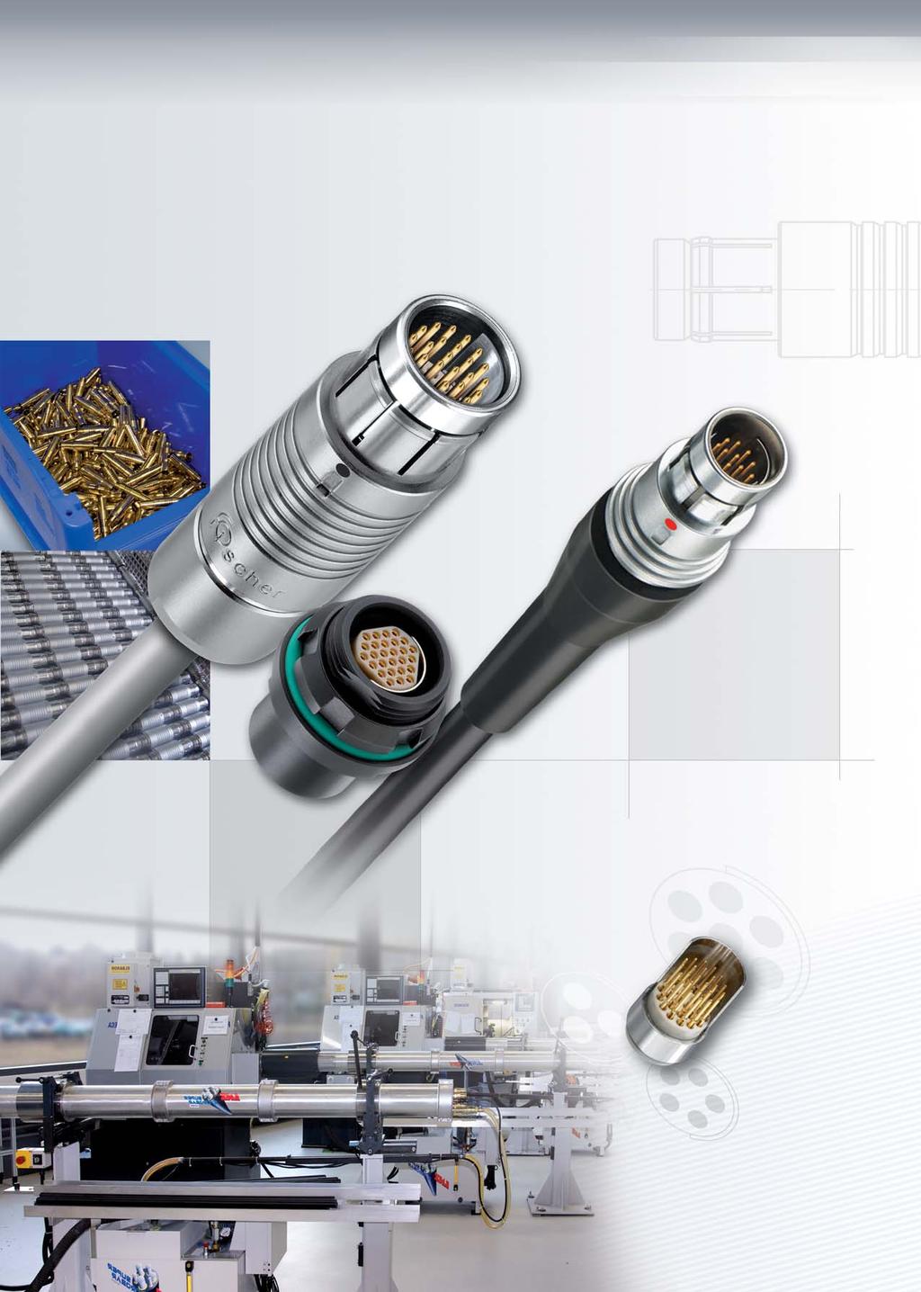
Multipole Low Voltage Connectors
|
|
|
- Lester Foster
- 5 years ago
- Views:
Transcription

1 Connectors 4


2 Introduction Key Features Wide range of body styles and sizes Unsealed, sealed or hermetic etic Signal or power Multipole up to 55 contacts Up to 30 A Standard or inverted polarity Solder, crimp or PCB contacts Guide mark standard Mechanical and color coding This catalogue covers our standard connector solutions. For thermocouple connectors, check our online documentation on For specific requests, hybrids or fiber optic configurations, please contact us. How to Order our Products? To find your local Fischer Connectors Office see Catalogue back cover or go to For General Ordering Information, see page 2-3 Cable Clamp Set should be ordered separately, see page 4-11 For details on Options, see page 4-10 For Accessories, see Section 11 For Tooling, see Section 12 Other Fischer Connectors Series with Multipole Low Voltage Contacts AluLite TM Series Plastic Series Disposable Fischer UltiMate TM Aluminium connectors ideal for ultralight or portable applications Plastic connectors ideal for lightweight applications Low cost, high performance connectors developped for disposable equipments High performance connectors specially designed for military land Forces Fischer AluLite TM Series Fischer 405 Series Fischer 4032 Series Fischer L.U.C TM Series Fischer LandForce TM Series 4-1
3 Contents Cable Mounted Plugs Body Style Selection (S/SC; SOV; SA; SV; SS/SSC; WSO) Dimensions Cable Mounted Receptacles Body Style Selection (K/KE; KS/KSE) Dimensions Panel Mounted Receptacles Body Style Selection (D; DEU/E; DB; DBEU/E; DBP; DBPU/E; DBPLU/E; DG/DGP; DBPC; WDE) Dimensions Panel Cut-Outs Panel Mounted Plugs Body Style Selection (SF; SFU/E; SFPU/E) Dimensions Panel Cut-Outs Panel Mounted Cable Receptacles Body Style Selection (DKBE; DK; DKE) Dimensions Panel Cut-Outs For all Multipole Low Voltage Electrical & Contact Specifications Options Cable Clamp Sets Cable Assembly Accessories Tooling Technical Information
4 Body Style Selection Cable Mounted Plugs Body Style S SC SOV SA SV SS SSC WSO Links to Detailed Information Protection Locking System Contacts Unsealed (IP50) Sealed up to IP68 None Push-Pull Emergency Release Lanyard Tamperproof Crimp Solder Sealed and Hermetic Connectors Page 13-8 Plug Locking Systems Page 2-7 Electrical & Contact Specifications Page 4-9 Housing Color Design Natural Chrome Black Chrome Shortened Body Straight Right Angle Options Page 4-10 Core Series Overview Page 2-1 Cabling Cable Clamp Sets Cable Clamp Sets Page 4-11 Overmoldable Heat Shrinkable Cable Assembly Section 3 Accessories Cable Bend Reliefs Protective Sleeves Sealing Caps Accessories Section Series 103 Series 1031 Series Dimensions Page Size 104 Series 105 Series 106 Series For more Information Visit: /technical 107 Series Plugs mate with receptacles. 4-3
5 Dimensions Cable Mounted Plugs S / SC Body Styles ~B ~A ød 1 2 Series A B D dmax 1 Torque 1 Unsealed Sealed SOV Body Style ~A ~B ød 1 2 Series A B D dmax 1 Torque 1 Unsealed Sealed Please contact us for additional information 107 All dimensions shown are in millimeters and are for reference only
6 Dimensions Cable Mounted Plugs SA Body Style ø1 ~B ~A ~B ~A ød ød 1 2 ~L ~L1 Series A B D L L1 dmax 1 Torque 1 Unsealed Sealed Please contact us for additional information 107 SV Body Style Series A B D D1 dmax 1 Torque 1 Unsealed Sealed Please contact us for additional information Torque are recommended values that may be influenced by the characteristics of the cable jacket. Tests have to be made to evaluate the exact values. To secure the cable clamp nut, we recommend the use of thread locking adhesive.
7 Dimensions Cable Mounted Plugs SS / SSC Body Styles ~B ~A 1 ød 1) Cable Assembly: Overmolding Options Series A B D D1 D2 dmax 1 Torque Please contact us for additional information 107 1) Max. cable diameter below shield. 2 WSO Body Style ~B ~A Cable Orientations: View from the back Up: Optional Suffix: -12H H 2 Right: Optional Suffix: -3H 1 Left: Optional Suffix: -9H ød Down: Standard Suffix: None All dimensions shown are in millimeters and are for reference only. Series A B D H dmax 1 Torque 1 2 Torque 2 Unsealed Sealed Please contact us for additional information 107 WSO is available for different cable orientations. When ordering, choose which suffix to use in cable orientations figure. Example: WSO 102 A with standard down cable orientation WSO 102 A H with left cable orientation 4-3-3
8 Body Style Selection Cable Mounted Receptacles Body Style K KE KS KSE Links to Detailed Information Protection Unsealed (IP50) Sealed up to IP68 Sealed and Hermetic Connectors Page 13-8 Contacts Crimp Solder Electrical & Contact Specifications Page 4-9 Housing Natural Chrome Black Chrome Shortened Body Options Page 4-10 Core Series Overview Page 2-1 Design Straight Right Angle Core Series Overview Page 2-1 Cabling Cable Clamp Sets Overmoldable Cable Clamp Sets Page 4-11 Cable Assembly Section 3 Heat Shrinkable Accessories Cable Bend Reliefs Protective Sleeves Sealing Caps Accessories Section Series 103 Series 1031 Series Dimensions Page Size 104 Series 105 Series For more Information Visit: Series 107 Series Plugs mate with receptacles. 4-4
9 Dimensions Cable Mounted Receptacles K / KE Body Styles ~A ød 1 2 Series A D dmax 1 Torque 1 Unsealed Sealed KS / KSE Body Styles ~A 1 2 ød 1) 1 2 Series A D D1 D2 dmax 1 Torque 1 2 Cable Assembly: Overmolding Options Please contact us for additional information 107 1) Max. cable diameter below shield. All dimensions shown are in millimeters and are for reference only. Torque are recommended values that may be influenced by the characteristics of the cable jacket. Tests have to be made to evaluate the exact values. To secure the cable clamp nut, we recommend the use of thread locking adhesive
10 Body Style Selection Panel Mounted Receptacles Body Style D DEU DEE DB DBEU DBEE DBP Protection Contacts Housing Color Unsealed (IP50) Sealed up to IP68 Hermetic Crimp Solder PCB Natural Chrome Black Chrome Right Angle Design Flush Front Projecting Bulkhead Feedthrough Assembly Front Mounting Rear Mounting Sealing Caps Accessories Spacers Color-Coded Washers Grounding Washers Locking Washers Decorative Nuts 102 Series 103 Series 1031 Series Size 104 Series 105 Series 106 Series 107 Series Plugs mate with receptacles. 4-5
11 Body Style Selection Panel Mounted Receptacles DBPU DBPE DBPLU DBPLE DG DGP DBPC WDE Links to Detailed Information Sealed and Hermetic Connectors Page 13-8 Electrical & Contact Specifications Page 4-9 Options Page 4-10 Core Series Overview Page 2-1 Core Series Overview Page 2-1 Accessories Section 11 Dimensions Page For more Information Visit: /technical 4-5-1
12 Dimensions Panel Mounted Receptacles D Body Style ~A M 1 ~A B min/max. C1 Series A B C1 D M Torque / x / x / x / x / x / x1 TX / x1 TX DEU / DEE Body Styles M B min/max. C1 2 Series A B C1 D M 1 Torque / x / x / x / x / x / x1 TX / x1 TX Torque are recommended values that may be influenced by the quality of the surface under the nut. Tests have to be made to evaluate the exact values.

13 Dimensions Panel Mounted Receptacles DB Body Style ~A C M B min/max. C1 Series A B min/max. C C1 D M Torque / x / x Please contact us for additional information / x / x Please contact us for additional information 107 DBEU / DBEE Body Styles ~A C M 1 B min/max. C1 2 Series A B min/max. C C1 D M 1 Torque / x / x / x / x / x / x1 TX / x1 TX All dimensions shown are in millimeters and are for reference only
14 Dimensions Panel Mounted Receptacles DBP Body Style ~A B min/max. C 1 M 2.54 ~E Series A B min/max. C D D1 E M 1) Torque / x TC / x1 - TF / x1 - TG / x1 - TK / x1 - TP Please contact us for additional information 107 1) Assembly tool for decorative slotted nut, see Tooling Page 12-1 for details. DBPU / DBPE Body Styles ~A with or without ground C B min/max. 1 M 2.54 ~E Series A B min/max. C D D1 E M 1) Torque / x TC / x1 15 TG / x1 15 TG / x1 - TK / x1 - TP Please contact us for additional information 107 1) Assembly tool for decorative slotted nut, see Tooling Page 12-1 for details Torque are recommended values that may be influenced by the quality of the surface under the nut. Tests have to be made to evaluate the exact values.
15 Dimensions Panel Mounted Receptacles DBPLU / DBPLE Body Styles with or without ground ~A C B min/max. ~A B min/max. 1 2 M 2.54 ~E 1 Series A B min/max. C D D1 E M 1 Torque / x / x / x / x / x Please contact us for additional information 107 DG / DGP Body Styles 2.54 E M Series A B min/max. D E M 1) Torque / x TC / x1 14 TF / x1 17 TG / x1 17 TK / x1 22 TP Please contact us for additional information 107 1) Assembly tool for decorative slotted nut, see Tooling Page 12-1 for details. All dimensions shown are in millimeters and are for reference only
16 Dimensions Panel Mounted Receptacles DBPC Body Style B min/max. C 1 M ~E ~A Series A B C D D1 E 1) M 2) Torque / x TC / x1 - TF / x1 - TG ) Please refer to online Dimensional Specifications for precise value and layout dimensions. 2) Assembly tool for decorative slotted nut, see Tooling Page 12-1 for details. DBPC Mounting Clamp 1 2 E A F C B Enables mounting directly to PCB with two screws Improves grounding of body to the PCB Series A B C E F Part Number ø 2.2x ø 2.9x Material : 1 - Nickel plated brass copper 2 - PBT Torque are recommended values that may be influenced by the quality of the surface under the nut. Tests have to be made to evaluate the exact values.
17 Dimensions Panel Mounted Receptacles WDE Body Style for 102, 103 and 104 Series A B min/max. C1 C 2 A M 1 B min/max. C1 A M 1 2 WDE Body Style for 105 Series WDE Body Style for 106 and 107 Series 1) M E min B min/max. C1 Series A B min/max C C1 D E min M 1 Torque / x / x Please contact us for additional information / x / x ) 74 0/ x1 TX ) 92 0/ x1 TX ) Feedthroughs of series 106 and 107 are supplied with slotted nuts. For nuts dimensions see Section 11 Accessories. 2) Assembly tool for side slotted nut, see Tooling Page 12-1 for details. The bulkhead feedthrough connector allows the passing of electrical signals and power through a panel via two cable plugs. The "A" version of the feedthrough accepts a type "A" plug on the flange side and a type "" plug on the threaded end, which is typically oriented toward the interior of the chassis. In the version "A" the connections "A" and "" are inverted. See A/ Polarity on Page Dimension "B max" specifies the maximum panel thickness. For panels thinner than the unthreaded section "E min", we can provide spacers as shown in Section 11 Accessories. 2) 2 All dimensions shown are in millimeters and are for reference only
18 Body Style Selection Panel Mounted Plugs Body Style SF SFU SFE SFPU SFPE Links to Detailed Information Protection Contacts Housing Color Unsealed (IP50) Sealed up to IP68 Hermetic Crimp Solder PCB Natural Chrome Black Chrome Sealed and Hermetic Connectors Page 13-8 Electrical & Contacts Specifications Page 4-9 Options Page 4-10 Assembly Front Mounting Rear Mounting Core Series Overview Page 2-1 Sealing Caps Spacers Accessories Color-Coded Washers Insulating Washers Grounding Washers Accessories Section 11 Locking Washers Decorative Nuts 102 Series 103 Series 1031 Series Dimensions Page Size 104 Series 105 Series 106 Series For more Information Visit: /technical 107 Series Plugs mate with receptacles. 4-6
19 Dimensions Panel Mounted Plugs SF Body Style ~A C ~A 1 C M B min/max. C1 Series A B min/max. C C1 D M Torque / x / x / x / x / x / x1 TX x1 TX SFU / SFE Body Styles M 2 B min/max C1 Series A B min/max. C C1 D M 1 Torque / x / x / x / x / x Please contact us for additional information 107 All dimensions shown are in millimeters and are for reference only
20 Dimensions Panel Mounted Plugs SFPU / SFPE Body Styles ~A with or without ground C B min/max. 1 2 M 2.54 ~E 1 Series A B min/max. C D D1 E M 1 Torque / x / x / x / x / x Please contact us for additional information Torque are recommended values that may be influenced by the quality of the surface under the nut. Tests have to be made to evaluate the exact values.
21 Body Style Selection Panel Mounted Cable Receptacles Body Style DKBE DK DKE Links to Detailed Information Protection Unsealed (IP50) Sealed up to IP68 Sealed and Hermetic Connectors Page 13-8 Contacts Crimp Solder Electrical & Contacts Specifications Page 4-9 Housing Color Natural Chrome Black Chrome Options Page 4-10 Design Flush Front Projecting Core Series Overview Page 2-1 Assembly Panel Mounted Front Mounting Core Series Overview Page 2-1 Rear Mounting Cable Clamp Sets Cable Clamp Sets Page 4-11 Cable Bend Reliefs Sealing Caps Accessories Spacers Color-Coded Washers Insulating Washers Grounding Washers Accessories Section 11 Locking Washers Decorative Nuts 102 Series 103 Series 1031 Series Dimensions Page Size 104 Series 105 Series For more Information Visit: Series 107 Series Plugs mate with receptacles. 4-7

22 Dimensions Panel Mounted Cable Receptacles DKBE Body Style M ~A B min/max. C ~A 3 ød ød Series A B min/max. C D d max D1 M 1 Torque Torque / x / x / x / x / x / x / x DK Body Style 1 2 M B min/max. C1 Series A B min/max. C1 D d max M 1 Torque Torque / x / x Please contact us for additional information / x / x / x TX / x TX Torque are recommended values that may be influenced by the characteristics of the cable jacket and by the quality of the surface under the nut. Tests have to be made to evaluate the exact values. To secure the cable clamp nut, we recommend the use of thread locking adhesive.
23 Dimensions Panel Mounted Cable Receptacles DKE Body Style for 102, 103 and 1031 Series ~A ød 1 2 M 3 B min/max. C1 Series A B min/max. C C1 D d max M 1 Torque Torque / x / x Please contact us for additional information DKE Body Style for 104, 105, 106 and 107 Series ~A M C ød B min/max. C1 Series A B min/max. C C1 D d max M 1 Torque Torque / x / x / x TX / x TX All dimensions shown are in millimeters and are for reference only
24 Dimensions Panel Cut-Outs The dimension of panel cut-outs varies according to the body style and size of the panel mounted connector. Refer to table below for more details. Check details on dimensional specifications on our web site: ø d Panel Mounted Receptacles Series D DEU DEE DB DBEU DBEE DBP DBPU DBPE DBPLU DBPLE DG DGP DBPC WDE ø d Panel Mounted Plugs Panel Mounted Cable Receptacles Series SF SFU SFE SFPU SFPE Series DK DKBE DKE ø d ø d All dimensions shown are in millimeters and are for reference only.
25 Electrical & Contact Specifications Contents A/ Polarity For all Body Styles (except WDE) For WDE Body Style Contact Types Solder Contacts PCB Contacts Crimp Contacts, Tooling For Multipole Low Voltage Connectors Contact Configurations Wire Size Test & Rated Voltages Current Rating 102 Series Series Series Series Series Series Series
26 Electrical & Contact Specifications A/ Polarity To protect users from contact with dangerous voltages, most Fischer connectors exist in two versions: Type "A" Standard Polarity: The contacts of the receptacle are protected against accidental touch. This version is recommended when voltage is present on the receptacle. Type "" Inverted Polarity: The contacts of the plug are protected against accidental touch. This version is recommended when voltage is present on the plug. Receptacle D Plug S Type "A" Standard Polarity Type "" Inverted Polarity Important: An "A" type connector can never be mated with a "" type connector. A plug "S" has the same housing in type "A" as in type "", but type "A" comes with unprotected contacts while type "" is equipped with touch-protected contacts. In most cases these are female contacts which are recessed in the insulator. For the exceptions, see High Voltage Connectors page 5-5 and Mixed High Voltage page 9-5 Bulkhead Feedthrough WDE: Type "A" is the standard version of the WDE. The flange side accepts an "A" type plug, and the threaded side accepts a "" type plug. Type "" plug (S) WDE, type "A" Type "A" plug (S) The "A" version of the WDE accepts a type "" plug at the flange side and accepts a type "A" plug at the threaded end
27 Electrical & Contact Specifications Contact Types The Fischer contact designs are highly reliable and are guaranteed up to 10,000 mating cycles. All standard brass and bronze contacts for use in the Core Series are screw machined, and all are gold plated over a nickel underplate. The current Fischer design has very low insertion forces, improved contact area, and can be machined and calibrated in one operation. The classic Fischer design, which has equivalent performance, is still in use on certain connectors. Most connectors are available with solder, crimp or PCB contacts and each type is optimized for a particular application. Fischer Connectors manufactures as well connectors with thermocouple contacts. Please check our online documentation on All contacts and connectors are RoHS compliant. Solder Contacts Solder contacts are the most versatile contact as they can be produced with any type of contact block material and can accept a wide range of wire sizes. The contacts are pre-installed in the insulator block, and the wires can be terminated with any appropriately sized soldering iron. Solder contacts may require operators who are qualified in specialized soldering techniques. PCB Contacts PCB contacts are available on some Panel Mounted Connectors. These connectors are designed to be mounted directly to a PCB or flex circuit, and can be used in wave solder operations for faster production assembly. The pin diameter has been necessarily reduced in the area that will mount to the PCB, and this can affect the current carrying capacity and voltage characteristics of the connector depending on the PCB design and assembly techniques. These requirements should be reviewed during the product design process. PCB pins are non standard for Cable Mounted products
28 Electrical & Contact Specifications Contact Types Crimp Contacts Crimp contacts are often used in higher volume applications, and offer the advantage of being able to replace individual contacts if they become damaged. Each contact has a selectively annealed area that is deformed during assembly by specialized tooling to assure proper termination of the wire to the contact. Special tools are also required to insert the contact into the insulator block. See Section 12 Tooling. Teflon insulator blocks are not compatible with crimp contacts, and crimp contacts only accept a limited range of wire sizes. Crimp contacts are not available in sealed or hermetic connectors. Tooling for Crimp Contacts Series Polarity Contact Diameter (mm) Contact Part Number Positioner Part Number Contact Part Number Positioner Part Number Contact Part Number See Section 12 Tooling, Page 12-2 for description of Crimping Tool and Positioner. Positioner Part Number Contact Part Number Positioner Part Number Contact Part Number Positioner Part Number 102 Male TX TX TX Female TX TX TX Male TX TX TX TX Female TX TX TX TX Male TX TX TX TX Female TX TX TX TX Male TX TX TX TX TX Female TX TX TX TX TX Male TX TX TX TX TX Female TX TX TX TX TX Crimp Tool Part Number TX TX TX TX TX
29 Electrical & Contact Specifications 102 Series = Standard = Option Type Pin Layout Number of Contacts Contact Termination Solder Crimp PCB Insulating Material Contact ø [mm] Solder Contacts 1) Wire Size 2) Crimp Contacts Test Voltage [V] in mated position AC rms Contact to Body Contact to Contact Contact to Body DC Contact to Contact Rated Voltage 4) r.m.s [V] Current Rating 3) [A] 102 A PEEK 0.9 max ø0.79mm AWG21 [1] AWG22 [7/30] max ø0.83mm min ø0.48mm AWG A PEEK 0.9 max ø0.79mm AWG21 [1] AWG22 [7/30] A PEEK 0.7 max ø0.79mm AWG21 [1] AWG22 [7/30] max ø0.62mm min ø0.38mm AWG A PEEK 0.7 max ø0.79mm AWG21 [1] AWG22 [7/30] max ø0.62mm min ø0.38mm AWG A PEEK 0.5 max ø0.43mm AWG26 [1] AWG28 [19/40] max ø0.43mm min ø0.20mm AWG A PEEK 0.5 max ø0.43mm AWG26 [1] AWG28 [19/40] ) Stranding values are in brackets. 2) For a given AWG, the diameter of some stranded conductor designs could exceptionally be larger than the hole diameter of the barrel. Testing may be required. 3) Recommended max. operating current per contact at 40 C temperature rise measured according to IEC b. 4) Recommended operating voltage at sea level measured according to IEC This rated voltage is a general purpose guideline where no other electrical safety standard applies. In cases where other standards rule a specific use of the connector, the application-specific safety criteria shall be considered first. This must be evaluated in the framework of equipment engineering. In cases where other calculation methods are preferred, please use the Test Voltage to determine the operating voltage. See page 13-6 for details. All dimensions shown are in millimeters and are for reference only
30 Electrical & Contact Specifications 103 and 1031 Series = Standard = Option Type Pin Layout Number of Contacts Contact Termination Solder Crimp PCB Insulating Material Contact ø [mm] Solder Contacts 1) Wire Size 2) Crimp Contacts Test Voltage [V] in mated position AC rms Contact to Body Contact to Contact Contact to Body DC Contact to Contact Rated Voltage 4) r.m.s [V] Current Rating 3) [A] 103 A PEEK 1.3 max ø1.18mm AWG17 [1] AWG18 [16/30] max ø1.18mm min ø0.58mm AWG A PEEK 1.3 max ø1.18mm AWG17 [1] AWG18 [16/30] A PEEK 0.9 max ø0.79mm AWG21 [1] AWG22 [7/30] A PEEK 0.9 max ø0.79mm AWG21 [1] AWG22 [7/30] max ø0.83mm min ø0.48mm AWG A PEEK 0.7 max ø0.79mm AWG21 [1] AWG22 [7/30] max ø0.62mm min ø0.38mm AWG A PEEK 0.7 max ø0.79mm AWG21 [1] AWG22 [7/30] max ø0.62mm min ø0.38mm AWG A PEEK 0.7 max ø0.79mm AWG21 [1] AWG22 [7/30] max ø0.62mm min ø0.38mm AWG A PEEK 0.5 max ø0.43mm AWG26 [1] AWG28 [19/40] max ø0.43mm min ø0.20mm AWG A PEEK 0.7 max ø0.79mm AWG21 [1] AWG22 [7/30] max ø0.62mm min ø0.38mm AWG A PEEK 0.7 max ø0.79mm AWG21 [1] AWG22 [7/30] max ø0.62mm min ø0.38mm AWG A PEEK 0.5 max ø0.43mm AWG26 [1] AWG28 [19/40] max ø0.43mm min ø0.20mm AWG ) Stranding values are in brackets. 2) For a given AWG, the diameter of some stranded conductor designs could exceptionally be larger than the hole diameter of the barrel. Testing may be required. 3) Recommended max. operating current per contact at 40 C temperature rise measured according to IEC b. 4) Recommended operating voltage at sea level measured according to IEC This rated voltage is a general purpose guideline where no other electrical safety standard applies. In cases where other standards rule a specific use of the connector, the application-specific safety criteria shall be considered first. This must be evaluated in the framework of equipment engineering. In cases where other calculation methods are preferred, please use the Test Voltage to determine the operating voltage. See page 13-6 for details
31 Electrical & Contact Specifications 104 Series = Standard = Option Type Pin Layout Number of Contacts Contact Termination Solder Crimp PCB Insulating Material Contact ø [mm] Solder Contacts 1) Wire Size 2) Crimp Contacts Test Voltage [V] in mated position AC rms Contact to Body Contact to Contact Contact to Body DC Contact to Contact Rated Voltage 4) r.m.s [V] Current Rating 3) [A] 104 A PEEK PTFE 1.6 max ø1.86mm AWG13 [1] AWG14 [7/22] A PEEK PBT 1.6 max ø1.86mm AWG13 [1] AWG14 [7/22] max ø1.78mm min ø1.17mm AWG A PEEK 1.3 max ø1.18mm AWG17 [1] AWG18 [16/30] max ø1.18mm min ø0.58mm AWG max ø2.48mm 104 A PBT AWG11 [1] AWG12 [7/20] max ø0.79mm AWG21 [1] AWG22 [7/30] A PEEK 1.3 max ø1.18mm AWG17 [1] AWG18 [16/30] A PEEK 0.9 max ø0.79mm AWG21 [1] AWG22 [7/30] max ø0.83mm min ø0.48mm AWG A PEEK 0.9 max ø0.79mm AWG21 [1] AWG22 [7/30] ) ) ) Stranding values are in brackets. 2) For a given AWG, the diameter of some stranded conductor designs could exceptionally be larger than the hole diameter of the barrel. Testing may be required. 3) Recommended max. operating current per contact at 40 C temperature rise measured according to IEC b. 4) Recommended operating voltage at sea level measured according to IEC This rated voltage is a general purpose guideline where no other electrical safety standard applies. In cases where other standards rule a specific use of the connector, the application-specific safety criteria shall be considered first. This must be evaluated in the framework of equipment engineering. In cases where other calculation methods are preferred, please use the Test Voltage to determine the operating voltage. See page 13-6 for details. 5) Test voltages between the contacts with the shortest distance. All dimensions shown are in millimeters and are for reference only
32 Electrical & Contact Specifications 104 Series = Standard = Option Type Pin Layout Number of Contacts Contact Termination Solder Crimp PCB Insulating Material Contact ø [mm] Solder Contacts 1) Wire Size 2) Crimp Contacts Test Voltage [V] in mated position AC rms Contact to Body Contact to Contact Contact to Body DC Contact to Contact Rated Voltage 4) r.m.s [V] Current Rating 3) [A] 104 A PEEK 0.9 max ø0.79mm AWG21 [1] AWG22 [7/30] max ø0.83mm min ø0.48mm AWG max ø1.18mm 104 A PEEK AWG17 [1] AWG18 [16/30] max ø0.79mm AWG21 [1] AWG22 [7/30] A PEEK 0.9 max ø0.79mm AWG21 [1] AWG22 [7/30] max ø0.83mm min ø0.48mm AWG A PEEK 0.7 max ø0.79mm AWG21 [1] AWG22 [7/30] max ø0.62mm min ø0.38mm AWG A PEEK 0.7 max ø0.79mm AWG21 [1] AWG22 [7/30] max ø0.62mm min ø0.38mm AWG A 124 5) 27 PEEK 0.5 1) Stranding values are in brackets. max ø0.43mm min ø0.20mm AWG ) For a given AWG, the diameter of some stranded conductor designs could exceptionally be larger than the hole diameter of the barrel. Testing may be required. 3) Recommended max. operating current per contact at 40 C temperature rise measured according to IEC b. 4) Recommended operating voltage at sea level measured according to IEC This rated voltage is a general purpose guideline where no other electrical safety standard applies. In cases where other standards rule a specific use of the connector, the application-specific safety criteria shall be considered first. This must be evaluated in the framework of equipment engineering. In cases where other calculation methods are preferred, please use the Test Voltage to determine the operating voltage. See page 13-6 for details. 5) This configuration has different environmental performances due to the use of another sealant material. Please contact us for more information
33 Electrical & Contact Specifications 105 Series = Standard = Option Type Pin Layout Number of Contacts Contact Termination Solder Crimp PCB Insulating Material Contact ø [mm] Solder Contacts 1) Wire Size 2) Crimp Contacts Test Voltage [V] in mated position AC rms Contact to Body Contact to Contact Contact to Body DC Contact to Contact Rated Voltage 4) r.m.s [V] Current Rating 3) [A] 105 A PEEK 2.0 max ø2.03mm AWG13 [1] AWG14 [7/22] A PEEK 3.0 max ø3.13mm AWG9 [1] AWG10 [105/30] A PEEK 2.0 max ø2.03mm AWG13 [1] AWG14 [7/22] A PEEK 2.0 max ø2.03mm AWG13 [1] AWG14 [7/22] max ø2.03mm 105 A 054 5) PEEK AWG13 [1] AWG14 [7/22] max ø1.18mm AWG17 [1] AWG18 [16/30] A PEEK PTFE 1.3 max ø1.18mm AWG17 [1] AWG18 [16/30] max ø2.48mm 105 A PEEK AWG11 [1] AWG12 [7/20] max ø1.18mm AWG17 [1] AWG18 [16/30] max ø2.03mm 105 A 101 5) PEEK AWG13 [1] AWG14 [7/22] max ø1.18mm AWG17 [1] AWG18 [16/30] ) Stranding values are in brackets. 2) For a given AWG, the diameter of some stranded conductor designs could exceptionally be larger than the hole diameter of the barrel. Testing may be required. 3) Recommended max. operating current per contact at 40 C temperature rise measured according to IEC b. 4) Recommended operating voltage at sea level measured according to IEC This rated voltage is a general purpose guideline where no other electrical safety standard applies. In cases where other standards rule a specific use of the connector, the application-specific safety criteria shall be considered first. This must be evaluated in the framework of equipment engineering. In cases where other calculation methods are preferred, please use the Test Voltage to determine the operating voltage. See page 13-6 for details. 5) Contact dia. 2.0 is positioned to make contact first and break last. All dimensions shown are in millimeters and are for reference only
34 Electrical & Contact Specifications 105 Series = Standard = Option Type Pin Layout Number of Contacts Contact Termination Solder Crimp PCB Insulating Material Contact ø [mm] Solder Contacts 1) Wire Size 2) Crimp Contacts Test Voltage [V] in mated position AC rms Contact to Body Contact to Contact Contact to Body DC Contact to Contact Rated Voltage 4) r.m.s [V] Current Rating 3) [A] 105 A PEEK 1.3 max ø1.18mm AWG17 [1] AWG18 [16/30] max ø1.18mm min ø0.58mm AWG A PEEK 1.3 max ø1.18mm AWG17 [1] AWG18 [16/30] A 104 5) A PEEK PEEK max ø1.18mm AWG17 [1] AWG18 [16/30] max ø0.79mm AWG21 [1] AWG22 [7/30] max ø1.18mm min ø0.58mm AWG18-24 max ø0.62mm min ø0.38mm AWG A PEEK 0.9 max ø0.79mm AWG21 [1] AWG22 [7/30] max ø0.83mm min ø0.48mm AWG A 110 6) PEEK max ø1.86mm AWG13 [1] AWG14 [7/22] max ø0.79mm AWG21 [1] AWG22 [7/30] A PEEK 0.9 max ø0.79mm AWG21 [1] AWG22 [7/30] max ø0.83mm min ø0.48mm AWG A PBT 0.7 max ø0.79mm AWG21 [1] AWG22 [7/30] A PEEK 0.7 max ø0.79mm AWG21 [1] AWG22 [7/30] max ø0.62mm min ø0.38mm AWG ) Stranding values are in brackets. 2) For a given AWG, the diameter of some stranded conductor designs could exceptionally be larger than the hole diameter of the barrel. Testing may be required. 3) Recommended max. operating current per contact at 40 C temperature rise measured according to IEC b. 4) Recommended operating voltage at sea level measured according to IEC This rated voltage is a general purpose guideline where no other electrical safety standard applies. In cases where other standards rule a specific use of the connector, the application-specific safety criteria shall be considered first. This must be evaluated in the framework of equipment engineering. In cases where other calculation methods are preferred, please use the Test Voltage to determine the operating voltage. See page 13-6 for details. 5) Contacts dia. 1.3 are positioned to make contact first and break last. 6) Contacts dia. 1.6 are positioned to make contact first and break last
35 Electrical & Contact Specifications 106 Series = Standard = Option Type Pin Layout Number of Contacts Contact Termination Solder Crimp PCB Insulating Material Contact ø [mm] Male Solder Contacts 1) Wire Size 2) Female Solder Contacts 1) Test Voltage [V] in mated position AC rms Contact to Body Contact to Contact Contact to Body DC Contact to Contact Rated Voltage 4) r.m.s [V] Current Rating 3) [A] 106 A 003 5) 3 PTFE PEEK 2.3 max ø2.13mm AWG12 [1] AWG14 [7/22] max ø2.28mm AWG12 [1] AWG14 [105/34] A 5) 6) PTFE PEEK 2.0 max ø2.08mm AWG12 [1] AWG14 [7/22] max ø2.03mm AWG13 [1] AWG14 [7/22] A PTFE PEEK 2.0 max ø2.08mm AWG12 [1] AWG14 [7/22] max ø2.03mm AWG13 [1] AWG14 [7/22] A PTFE PEEK 2.0 max ø2.08mm AWG12 [1] AWG14 [7/22] max ø2.03mm AWG13 [1] AWG14 [7/22] A PTFE PEEK 1.3 max ø1.18mm AWG17 [1] AWG18 [16/30] max ø1.23mm AWG17 [1] AWG18 [16/30] A PTFE PEEK 1.3 max ø1.18mm AWG17 [1] AWG18 [16/30] max ø1.18mm AWG17 [1] AWG18 [16/30] ) Stranding values are in brackets. 2) For a given AWG, the diameter of some stranded conductor designs could exceptionally be larger than the hole diameter of the barrel. Testing may be required. 3) Recommended max. operating current per contact at 40 C temperature rise measured according to IEC b. 4) Recommended operating voltage at sea level measured according to IEC This rated voltage is a general purpose guideline where no other electrical safety standard applies. In cases where other standards rule a specific use of the connector, the application-specific safety criteria shall be considered first. This must be evaluated in the framework of equipment engineering. In cases where other calculation methods are preferred, please use the Test Voltage to determine the operating voltage. See page 13-6 for details. 5) The contact solder cups are specially insulated. 6) Contact Number 1 is positioned to make contact first and break last. All dimensions shown are in millimeters and are for reference only
36 Electrical & Contact Specifications 107 Series = Standard = Option Type Pin Layout Number of Contacts Contact Termination Solder Crimp PCB Insulating Material Contact ø [mm] Male Solder Contacts 1) Wire size 2) Female Solder Contacts 1) Test Voltage [V] in mated position AC rms Contact to Body Contact to Contact Contact to Body DC Contact to Contact Rated Voltage 4) r.m.s [V] Current Rating 3) [A] 107 A PTFE 2.3 max ø2.93mm AWG9 [1] AWG10 [37/26] max ø2.28mm AWG12 [1] AWG14 [105/34] A PTFE PEEK 2.3 max ø2.93mm AWG9 [1] AWG10 [37/26] max ø2.28mm AWG12 [1] AWG14 [105/34] A PTFE PEEK 2.0 max ø2.08mm AWG12 [1] AWG14 [7/22] max ø2.03mm AWG13 [1] AWG14 [7/22] A PTFE PEEK 1.3 max ø1.18mm AWG17 [1] AWG18 [16/30] max ø1.18mm AWG17 [1] AWG18 [16/30] A PTFE PEEK 1.3 max ø1.18mm AWG17 [1] AWG18 [16/30] max ø1.18mm AWG17 [1] AWG18 [16/30] A PTFE PEEK max ø1.18mm AWG17 [1] AWG18 [16/30] max ø0.79mm AWG21 [1] AWG22 [7/30] max ø1.18mm AWG17 [1] AWG18 [16/30] max ø0.88mm AWG20 [1] AWG22 [19/34] ) Stranding values are in brackets. 2) For a given AWG, the diameter of some stranded conductor designs could exceptionally be larger than the hole diameter of the barrel. Testing may be required. 3) Recommended max. operating current per contact at 40 C temperature rise measured according to IEC b. 4) Recommended operating voltage at sea level measured according to IEC This rated voltage is a general purpose guideline where no other electrical safety standard applies. In cases where other standards rule a specific use of the connector, the application-specific safety criteria shall be considered first. This must be evaluated in the framework of equipment engineering. In cases where other calculation methods are preferred, please use the Test Voltage to determine the operating voltage. See page 13-6 for details
37 Options Contents Options Presentation Connector Housing Colors Cable Bend Reliefs and Clamp Nut Types Mechanical Coding Options Part Numbering Multipole Low Voltage, High Voltage and Mixed High Voltage Connectors


38 Options Housing Colors and Cable Bend Reliefs Connector Housing Colors All the body styles of our Core Product Line are available in two colors: Natural chrome connector housing with red guide mark. Non reflective black chrome housing with white guide mark. Guide mark is standard for Multipole Low and High Voltage, Mixed Multipole and Mixed Coax Connectors. Color-coding is achieved by using accessories: Cable Bend Reliefs for Cable Connectors. Washers for Panel Connectors. For detailed information on Cable Bend Reliefs and Washers, See Section 11 Accessories. Our AluLite TM connector Series ideal for ultralight product development features a wide array of housing colors. For more, download AluLite TM series catalogue at Cable Bend Reliefs and Clamp Nut Types A cable bend relief is a useful accessory for connectors mounted with cable clamp sets (S/SC; SOV; SA; SV; WSO; K/KE; DK; DKE; DBKE). It enables to: Prevent cable torsion, enhancing your connections efficiency. Color-code your connectors for easy identification. Cable bend reliefs require special clamp nuts, thus are linked with your selection of options For detailed information on cable bend reliefs and washers, see Section 11 Accessories.

39 Options Mechanical Coding For Easy Connect / Disconnect Operations Our contact blocks are engineered with arc-shape metal guides, which ensure precise alignement of connectors during the mating process. This guiding mechanism provides: Increased safety and user friendliness by preventing misconnection. Easy mating cycles, can be blind-mated. Increased equipment life span by optimally protecting the contacts. Keying Codes Options All Multipole body styles are mechanically coded. Code 1 is the standard, but other codes can be requested (See table below). Female Block Male Block Code 1 Code 2 Code 3 Other keying codes are available on request, please contact us
40 Options Multipole Low Voltage, High Voltage & Mixed Connectors 1 Housing Color Which housing color do you need? NATURAL CHROME with Red Guide Mark 2 Contact Block Material Which contact block material do you need? PTFE PBT PEEK 3 Contact Type Which contact type do you need? Solder Solder Crimp 1) Solder Crimp 1) 4 Keying Code Which keying code do you need? Code Code ) Crimp contacts are not an option for sealed or hermetic connectors. Code Cable Bend Relief Do you need a cable bend relief, and if yes which color? Applicable for Last Digit Description 0 Clamp nut without bend relief 1 Clamp nut with white bend relief Cable Mounted Plugs & Receptacles using Cable Clamp Sets Except SS/SSC - KS/KSE 2 Clamp nut with black bend relief 3 Clamp nut with green bend relief 4 Clamp nut with blue bend relief 5 Clamp nut with yellow bend relief 6 Clamp nut with red bend relief 7 Clamp nut with grey bend relief Contact Type for Panel Mounted Connectors Applicable for Last Digit Description Front Mounted : D - DEU/E - DB - DBEU/E - DG - SF - SFU/E Rear Mounted : DBP - DBPU/E - DBPLU/E - DGP - SFPU/E 0 Standard : solder contacts 9 With PCB (Printed Circuit Board) contacts instead of solder contacts 0 Standard : PCB (Printed Circuit Board) contacts 9 With solder contacts instead of PCB (Printed Circuit Board) contacts Design and Accessories Applicable for Extensions Description Receptacles N E G B D F Nickel plated body with bright finish EPDM interface O-ring Ground tag if solder contact or Ground pin if PCB contact Black Nut Decorative slotted nut Decorative nut (with 2 flats) Other options are available on request, please contact us
41 Options Multipole Low Voltage, High Voltage & Mixed Connectors BLACK CHROME with White Guide Mark PTFE PBT PEEK Solder Solder Crimp 1) Solder Crimp 1) ) Crimp contacts are not an option for sealed or hermetic connectors. Examples Plugs S 102 A Natural chrome housing color with PEEK contact block, solder contacts, keying code 1, clamp nut without bend relief and without cable clamp set ( To be ordered separately) S 102 A Natural chrome housing color with PEEK contact block, solder contacts, keying code 2, clamp nut with black bend relief, without cable clamp set SS 102 A Black chrome housing color with PEEK contact block, crimp contacts, keying code 2 Receptacles D 102 A Natural chrome housing color with PEEK contact block, solder contacts, keying code 1 D 102 A Black chrome housing color with PEEK contact block, crimp contacts, keying code 2 DBPU 102 A G Natural chrome housing color with PEEK contact block, PCB contacts, keying code 1 and ground pin DBPU 102 A NBE Nickel plated body with PEEK contact block, solder contacts, keying code 1, with black nut and EPDM interface O-ring
42 Cable Clamp Sets Contents Introduction Overview: S, U and E Types Part Numbering Dimensions S/SC; SOV; SA; SV; K/KE; DK; DKE and DKBE; Body Styles 102 Series 103 Series 1031 Series 104 Series 105 Series 106 Series 107 Series Dimensions WSO Body Style 102, 103, 1031, 104 and 105 Series
43 Cable Clamp Sets Introduction To guarantee excellent cable retention and strain relief, Fischer Connectors provides robust and high quality cable clamp sets: Collet style clamp system retaining cable over large jacket surface area. Protection of small diameters and delicate conductors. Can be combined with cable bend reliefs for optimal performance. See Accessories, page Cable clamp sets are suitable for all cable mounted connectors, except SS/SSC and KS/KSE. For these specific body styles, see Section 3 Cable Assembly for overmolding or heat shrinking techniques. Overview : S, U and E Cable Clamp Sets Fischer Connectors offers three types of cable clamps sets. The table below will help you select the one corresponding to your needs. Cable Clamp Set Do you need the interface between the cable and the connector to be sealed? Do you need the connector to be terminated to the cable shield? Unsealed Sealed Unshielded Shielded S - Shielded U - Unshielded E - Environmental For 106 and 107 connector series, only S and E cable clamp sets are available. See page and for details. Part Numbering Below Cable Clamp Sets Should be Ordered Separately Below Cable Clamp Sets are Included with Connector Multipole Low Voltage Triax Coax Low Voltage Coax High Voltage S 102 A Examples Connector ordering line Shielded (S) or Environmental (E) Cable Clamp Set diameter should be added to the connector part number separated by ø. Examples For S - Shielded Clamp Sets S 102 A K 103 A ø6.2 Clamp Set ordering line For E - Environmental Clamp Sets E /2.0 KE 103 A ø6.2 See following pages for Cable Clamp Set selection. See following pages for S or E Cable Clamp Set selection
44 Cable Clamp Sets 102 Series S - Shielded Sleeve Shielded Clamp Shielded cable clamp with sleeve. Collet E /2.1 + A E /2.6 + A E /3.1 + A E /3.6 + A Collet E /4.1 + A E /4.3 + A A U - Unshielded Unshielded Clamp Unshielded, one-piece cable clamp. Collet E / E / E /3.5 Collet E / E /4.7 E - Environmental Sleeve Washer Seal Cable Clamp Environmentally sealed clamp for use with shielded or unshielded cables. Collet E /2.1 + B E /2.6 + B E /3.1 + B Collet E /3.6 + B E /4.1 + B E /4.3 + B 1) For ordering information see Page
45 Cable Clamp Sets 103 Series S - Shielded Sleeve Washer Shielded Clamp Shielded cable clamp with washer and sleeve. Collet PEEK or PBT Insulator E /2.2 +B E /2.7 +B E /3.2 +B E /3.7 +B E /4.2 +B Collet PEEK or PBT Insulator E /4.7 +B E /5.2 +B E /5.7 +B E /6.2 +B E /6.7 +B U - Unshielded Cable Clamp Unshielded, one-piece cable clamp. Collet PEEK or PBT Insulator E / E / E / E /5.2 Collet PEEK or PBT Insulator E / E / E /6.7 E - Environmental Washer Sleeve Ring Seal Cable Clamp Environmentally sealed clamp for use with shielded or unshielded cables. Collet PEEK or PBT Insulator E /2.2 + B E /2.7 + B E /3.2 + B E /3.7 + B E /4.2 + B Collet PEEK or PBT Insulator E /4.7 + B E /5.2 + B E /5.7 + B E /6.2 + B 1) For ordering information see Page All dimensions shown are in millimeters and are for reference only
46 Cable Clamp Sets 1031 Series S - Shielded Sleeve Washer Shielded Clamp Shielded cable clamp with washer and sleeve. Collet E / E / E / E / E /4.7 Collet E / E / E / E / E /7.2 U - Unshielded Unshielded Clamp Unshielded, one-piece cable clamp. Collet E / E / E / E / E /4.7 Collet E / E / E / E / E /7.2 E - Environmental Washer Sleeve Ring Seal Cable Clamp Environmentally sealed clamp for use with shielded or unshielded cables. Collet E / E / E / E / E /4.7 Collet E / E / E / E /6.7 1) For ordering information see Page

47 Cable Clamp Sets 104 Series S - Shielded Sleeve Spacer Shielded Clamp Shielded cable clamp with spacer and sleeve. Cable dia. Collet PEEK or PBT Insulator Plug Receptacle E /4.0 + B E /4.0 + C E /4.7 + B E /4.7 + C E /5.7 + B E /5.7 + C Cable dia. Collet PEEK or PBT Insulator Plug Receptacle E /6.7 + B E /6.7 + C E /7.7 + B E /7.7 + C E /8.7 + B E /8.7 + C E /9.1 + B E /9.1 + C U - Unshielded Cable Clamp Unshielded, one-piece cable clamp. Collet PEEK or PBT Insulator E / E / E / E /6.7 Collet PEEK or PBT Insulator E / E / E /8.7 E - Environmental Sleeve Ring Washer Seal Cable Clamp Environmentally sealed clamp for use with shielded or unshielded cables. Cable dia. Collet PEEK or PBT Insulator Plug Receptacle E /4.0 + B E /4.0 + C E /4.7 + B E /4.7 + C E /5.7 + B E /5.7 + C Cable dia. Collet PEEK or PBT Insulator Plug Receptacle E /6.7 + B E /6.7 + C E /7.7 + B E /7.7 + C E /8.7 + B E /8.7 + C 1) For ordering information see Page All dimensions shown are in millimeters and are for reference only
48 Cable Clamp Sets 105 Series S - Shielded Sleeve Spacer Shielded Clamp Shielded cable clamp with spacer and sleeve. Collet PEEK or PBT Insulator E /4.2 + B E /5.2 + B E /6.2 + B E /7.2 + B Collet PEEK or PBT Insulator E /8.2 + B E /9.2 + B E / B E / B U - Unshielded Cable Clamp Unshielded, one-piece cable clamp. Collet PEEK or PBT Insulator E / E / E / E /6.5 Collet PEEK or PBT Insulator E / E / E / E /10.5 E - Environmental Sleeve Ring Washer Seal Cable Clamp Environmentally sealed clamp for use with shielded or unshielded cables. Collet PEEK or PBT Insulator E /4.2 + B E /5.2 + B E /6.2 + B E /7.2 + B Collet PEEK or PBT Insulator E /8.2 + B E /9.2 + B E / B E / B 1I For ordering information see Page
49 Cable Clamp Sets 106 Series S - Shielded Sleeve Spacer Shielded Clamp Shielded cable clamp with spacer and sleeve. Collet PTFE Insulator Plug Receptacle E /5.2 E / E /6.2 E / E /7.2 E / E /8.2 E / E /9.2 E / E /10.2 E / E /11.2 E / E /12.2 E /12.2 Shielded cable clamps with washers and sleeves. Collet PTFE Insulator Plug Receptacle E /13.2 E / E /14.2 E / E /15.2 E / E /16.2 E / E /17.2 E / E /18.2 E / E /19.2 E /19.2 E - Environmental Washer Sleeve Ring Seal Cable Clamp Environmentally sealed clamp for use with shielded or unshielded cables. Collet PTFE Insulator Plug Receptacle E /5.2 E / E /6.2 E / E /7.2 E / E /8.2 E / E /9.2 E / E /10.2 E / E /11.2 E / E /12.2 E /12.2 Collet PTFE Insulator Plug Receptacle E /13.2 E / E /14.2 E / E /15.2 E / E /16.2 E / E /17.2 E / E /18.2 E / E /19.2 E /19.2 1) For ordering information see Page All dimensions shown are in millimeters and are for reference only

50 Cable Clamp Sets 107 Series S - Shielded Sleeve Spacer Shielded Clamp Shielded cable clamp with spacer and sleeve. Collet PTFE insulator E / E / E / E / E / E / E / E /14.2 Collet PTFE insulator E / E / E / E / E / E / E / E /22.7 E - Environmental Washer Sleeve Ring Seal Cable Clamp Environmentally sealed clamp for use with shielded or unshielded cables. Collet PTFE insulator E / E / E / E / E / E / E / E /14.2 Collet PTFE insulator E / E / E / E / E / E / E / E /22.7 1) For ordering information see Page

51 Cable Clamp Sets WSO 102, 103, 1031, 104 and 105 Series S-Shielded or U-Unshielded (Unsealed) E-Environmental (Sealed) Ring Seal Rings Cable Clamp Cable Clamp Cable Series dia. Clamp Unsealed Sealed E /2.1 E / E /2.6 E / E /3.1 E / E /3.6 E / E /4.1 E / E /4.3 E / E / E /2.2 E / E /2.7 E / E /3.2 E / E /3.7 E / E /4.2 E / E /4.7 E / E /5.2 E / E /5.7 E / E /6.2 E / E /6.7 - Series Cable dia. Clamp Unsealed Sealed E /2.7 E / E /3.2 E / E /3.7 E / E /4.2 E / E /4.7 E / E /5.2 E / E /5.7 E / E /6.2 E / E /6.7 E / E / E /4.0 E / E /4.7 E / E /5.7 E / E /6.7 E / E /7.7 E / E /8.7 E / E /4.2 E / E /5.2 E / E /6.2 E / E /7.2 E / E /8.2 E / E /9.2 E / E /10.0 E / E /10.7 E /10.7 1) For ordering information see Page All dimensions shown are in millimeters and are for reference only

52 4-12
FISCHER CORE SERIES BRASS
 TECHNICL SPECIFICTIONS FISCHER CORE SERIES Fischer Connectors S ll rights reserved Web version 1.6-06.2017 Changes without prior notice Table of contents NY SIE, NY CONFIGURTION, NY PPLICTION FISCHER CORE
FISCHER CORE SERIES BRASS
 FISCHER CORE SERIES BRSS CHPTERS B1 B2 B3 B4 B5 B6 INTRODUCTION MULTIPOLE VOLTGE COX VOLTGE TRIX MIXED COX & HIGH VOLTGE CCESSORIES & TOOLING BRSS B1 CHPTER FISCHER CORE SERIES BRSS INTRODUCTION TBLE OF
FISCHER CORE SERIES STAINLESS STEEL
 TECHNICAL SPECIFICATIONS FISCHER CORE SERIES Fischer Connectors SA All rights reserved Web version 1.6-06.2017 Changes without prior notice FISCHER CORE SERIES FISCHER CORE SERIES KEY FEATURES The Fischer
fischer ultralight connectors AluLite series new Edition 1.0
 fischer ultralight connectors AluLite series new Edition.0 fischer ultralight connectors New AluLite series When weight matters Are weight considerations significant in the design and development of your
FISCHER ULTIMATE TM SERIES RUGGED COMPACT LIGHTWEIGHT KEY FEATURES
 H CHAPTER PAGES FISCHER TM SERIES RUGGED COMPACT LIGHTWEIGHT KEY FEATURES IP68 to -0m / IP69 / Hermetic 60 EMC shielding High corrosion resistance 0,000 mating cycles H - FISCHER TM SERIES Table of contents
GENERAL CATALOG THE RELIABLE EXPERT
 GENERAL CATALOG CORE ULTIMATE FIBEROPTIC MINIMAX THE RELIABLE EXPERT For over 60 years, you our clients and partners have been our main focus. Finding ways to satisfy you has constantly and naturally guided
FISCHER FREEDOM TM SERIES
 K CHAPTER FISCHER TM SERIES EASY MATING EASY CLEANING EASY INTEGRATION KEY FEATURES No key code: 360 mating freedom & optimized cable management Membrane-sealed contacts (patent pending) Low profile IP68
K CHAPTER FREEDOM TM SERIES EASY MATING EASY CLEANING EASY INTEGRATION FISCHER KEY FEATURES
 K CHAPTER FISCHER TM SERIES EASY MATING EASY CLEANING EASY INTEGRATION KEY FEATURES No key code: 360 mating freedom & optimized cable management Membrane-sealed contacts (patent pending) Low profile IP68
DISPOSABLE COST-EFFECTIVE EASY TO USE MODULAR KEY FEATURES
 B10 CHAPTER FISCHER CORE SERIES DISPO COST-EFFECTIVE EASY TO USE MODULAR KEY FEATURES Sterilizable (EtO), gamma) Color-coded for easy integration Single or two-piece shell Lightweight and shock resistant
MMC RTX series EN3716
 MMC RTX series EN3716 7 CONTENTS Page Introduction... 7-4 Application 7-4 Features... 7-4 Product overview... 7-5 Electrical characteristics... 7-6 Mechanical & environmental characteristics... 7-6 Products
SMB LOCK Introduction Characteristics Straight plugs Right angle plugs SMB limited detent (SMB-A) Receptacles...
 Receptacles...") CONTENTS PAGE SMB Introduction... 4 General... 5 Finder guide... 6 Interface... 7 Characteristics...8-9 Straight plugs...0- Right angle plugs...- Jacks... 3 Bulkhead jacks...4-5 Receptacles...6-7 PCB receptacles...
CONTENTS PAGE SMB Introduction... 4 General... 5 Finder guide... 6 Interface... 7 Characteristics...8-9 Straight plugs...0- Right angle plugs...- Jacks... 3 Bulkhead jacks...4-5 Receptacles...6-7 PCB receptacles...
Operating voltage up to 5 kvdc Operating current up to 4,5 A 2-6 high voltage contacts Quick and easy assembling Protection class IP68 acc.
 Operating voltage up to 5 kvdc Operating current up to 4,5 A 2-6 high voltage contacts Quick and easy assembling Protection class IP68 acc. DIN EN 60529 General characteristics and technical data Series
General characteristics and technical data Series MCS
 MOD M MC MCS VP 100 S Operating voltage up to 5 kvdc Operating current up to 4,5 A 2-6 high voltage contacts Quick and easy assembling Protection class IP68 acc. DIN EN 60529 General characteristics and
HERMETIC. Hermetic Connectors. High Performance Sealing Solutions
 HERMETIC Hermetic Connectors High Performance Sealing Solutions Hermetic Connectors 38999 QPL Qualified Presentation Based on glass to metal seal technology, SOURIAU offers hermetic connectors to cover
RP SMA Male Connector Crimp/Solder Attachment for RG174, RG316, RG188, PE-B100, PE-C100, inch, LMR-100
 RP SMA Male Connector Crimp/Solder Attachment for RG174, RG316, RG188, PE-B100, PE-C100, 0100 inch, LMR-100 RF Connectors Technical Data Sheet PE4771 Configuration SMA Male Reverse Polarity Connector MIL-STD-348
Our Most Important Connection is with You. SECTION 2 SMPM / SMP / SMP-LOCK / SMP-COM R201 / R222 / R222L / R2229
 SECTION 2 SMPM / SMP / SMP-LOCK / SMP-COM R201 / R222 / R222L / R2229 Contents SMPM Introduction... 2-4 Interface... 2-5 Characteristics... 2-6 Plugs and Jacks... 2-7 Receptacles and panel shrouds... 2-8
SMA CONTENTS PAGE 9-3
 CONTENTS PAGE SMA Introduction... 4 General... 5 Finder guide...6-7 Interface... 8 Characteristics...9-10 Straight plugs...11-12 Right angle plugs...13-14 Straight jacks... 14 Straight flange jacks...14-15
HyperGrip - Push/Pull Plastic Circular Connectors
 A B C D E F G H J K HG2 HG3 HG4 Ø1.014 [25.76] 1.220 [30.98] Ø0.866 [22.00] 0.272 [6.91] 1.637 [41.59] 3.265 [82.93] Ø0.502 [12.75] Ø0.656 [16.66] 2.700 [68.56] 3.724 [94.60] Ø1.172 [29.77] 1.137 [28.87]
8STA/8TA Series. Compact Circular Connectors Derived from MIL-DTL & JN1003. Connection Technologies
 8STA/8TA Series Compact Circular Connectors Derived from MIL-DTL-38999 & JN1003 Connection Technologies 8STA/8TA Series Contents Overview Presentation... 06 Applications... 06 Features & benefits... 07
EPIC CIRCON M23 Series
 M23 Series EPIC EPIC CIRCON M23 Series Application Advantage Rugged nickel-plated, die-cast zinc body Positive vibration protection for use with motor drives and moving assemblies Integral EMC cable gland
8D Series D38999 Stainless Steel Series
 Connector part numbers Basic Series 8D 0-11 K 35 P N L Locking type: None: Receptacle or plug with standard locking V: Plug with reinforced locking Shell style: 0: Square flange receptacle 7: Jam nut receptacle
Application Guide HOW TO INTEGRATE THE FISCHER L.U.C. TM INTO YOUR APPLICATION. Fischer L.U.C. CONTENTS
 Fischer Connectors SA Saint-Prex, Switzerland Phone +41 21 800 95 95 Fax +41 21 800 39 24 www.fischerconnectors.com mail@fischerconnectors.ch Application Guide HOW TO INTEGRATE THE FISCHER L.U.C. TM INTO
RP SMA Female Connector Crimp/Solder Attachment For RG178, RG196
 RP SMA Female Connector Crimp/Solder Attachment For RG178, RG196 TECHNICAL DATA SHEET PE4799 RP SMA Female Connector Crimp/Solder Attachment For RG178, RG196 Configuration Connector Connector Specification
EN3716 SAE AS81659 ARINC
 6 DSX RTX Series series SAE AS81659 EN3716 ARINC 404 Page Introduction... 6-4 Applications... 6-5 DSX SAE AS81659 Product overview... 6-6 Technical characteristics :... 6-7 & 6-8 Electrical... 6-7 Mechanical
Varicon. Series " x.130" x.150" Grid Pattern FEATURES TECHNICAL SPECIFICATIONS
 Series 8016.075" x.130" x.150" Grid Pattern FEATURES Available in five sizes: 20, 38, 56, 90 and 120 contacts Insertable / removable Varilok contacts Crimp, solder, solderless wrap, and taper tab terminations
Varicon. Series " x.130" x.150" Grid Pattern FEATURES TECHNICAL SPECIFICATIONS
 Series 8016.075" x.130" x.150" Grid Pattern FEATURES Available in five sizes: 20, 38, 56, 90 and 120 contacts Insertable / removable Varilok contacts Crimp, solder, solderless wrap, and taper tab terminations
M8 Series. Key features: BUCCANEER
 Bulgin s M8 circular connectors and overmolded cables are designed to fulfil the ever growing demand for sensor, actuator and data connections in process control, industrial machinery and factory automation
Operating voltage up to 5 kvdc Operating current up to 4,5 A 2-6 High voltage contacts Quick and easy assembling Protection class IP68 acc.
 Operating voltage up to 5 kvdc Operating current up to 4,5 A 2-6 High voltage contacts Quick and easy assembling Protection class IP68 acc. DIN EN 60529 General characteristics and technical data Series
CYLER. Catalogue. Cyler Technology Limited cylerconnectors. Push-Pull connectors
 Push-Pull connectors Catalogue cylerconnectors Selection Guide Where and Why Push-Pull? Industrial and Automation Medical electronics Telecommunication Test and Measurement Quality aesthetics for more
Amphenol LTW FLO Products Series. Market
 FLO Series FLO I Product Series Amphenol LTW FLO Products Series A new product line of metal push-pull connector series intermateable with Fischer, Lemo, and ODU. FLO series offers a quick and easy mating
SERIES MHV (H4) HIGH VOLTAGE CONNECTORS
 HIGH VOLTAGE CONNECTORS") SERIES MHV (H4) HIGH VOLTAGE CONNECTORS DESCRIPTION CONTENTS PAGE HUBER+SUHNER MHV connectors are coaxial miniature high voltage (MHV = Miniature High Voltage) connectors with 5 kv rms test voltage (mated
SERIES MHV (H4) HIGH VOLTAGE CONNECTORS DESCRIPTION CONTENTS PAGE HUBER+SUHNER MHV connectors are coaxial miniature high voltage (MHV = Miniature High Voltage) connectors with 5 kv rms test voltage (mated
Table of Contents SMA CONNECTORS
 Table of Contents 45 SMA Connectors 3 MMCX Connectors 50 Ohm Connectors Specifications...46 Quick Connect...49 Semi-Rigid & Flexible Cable...50 PC Mount...56 Bulkhead & Panel Mount...62 Self-Fixture End
SERIES BMA, SUBMINIATURE BLIND MATE CONNECTORS
 SERIES, SUBMINIATURE BLIND MATE CONNECTORS DESCRIPTION CONTENTS PAGE HUBER+SUHNER blind mate connectors open up special dimensions in microwave applications up to 18 GHz. HUBER+SUHNER offers a range of
POLAMCO HIGH POWER CONNECTORS STYLE
 POLAMCO HIGH POWER CONNECTORS 38999 STYLE Robust & reliable connectors designed for harsh environments Contents Part Description System... 4 Materials... 4 Plating Options... 5 SECTION ONE: Plugs 1.1 Shielded
RA CONNECTOR IDC. 1Certified LR Features. Standards. Disconnectable Insulation displacement connectors for 1.27mm pitch ribbon cables. 2.
 IDC mm pitch R CONNECTOR IDC Disconnectable Insulation displacement connectors for 1.2mm pitch ribbon cables Features Twin U-slot ID section The twin U-slot is the most important IDC element in JST s R
Modular Bayonet connectors: a flexible solution for data and signals transmission in railways harsh environment.
 GM Modular Bayonet connectors: a flexible solution for data and signals transmission in railways harsh environment. Passenger control Networking and lighting control Diagnostic support for brakes, motors
TNC Series Series C TN 114
 TNC Series TNC Series 114 TNC Interface Mating Dimensions (Per MIL-STD-348) TNC Interface Dimensions MALE Inches/Millimeters 3 Minimum Nominal Maximum LTR in. mm in. mm in. mm A.440 11.17 B.314 7.98.315
MCX Connectors Specifications Flexible Cable Semi-Rigid Cable Panel Mount PCB Mount... 22
 Section Index Connectors Specifications... 17 Flexible Cable... 19 Semi-Rigid Cable... 20 Panel Mount... 21 PCB Mount... 22 Other Information Assembly Instructions... 176 Cable Assembly... 166 Cable Information...
EPIC CIRCON M23 Series
 CIRCON M23 Series Application Advantage Rugged nickel-plated, die-cast zinc body Positive vibration protection for use with motor drives and moving assemblies Integral EMC cable gland provides strain relief,
Luminus Series Amphenol Pcd
 Luminus Series Amphenol Pcd Amphenol Pcd Pcd is is one one of of the the world s leading suppliers of of interconnect products for for Military, Commercial Aerospace and and Industrial applications. Located
SMB Connectors Specifications Flexible Cable Bulkhead PCB Mount... 66
 Section Index Connectors Specifications... 62 Flexible Cable... 64 Bulkhead... 65 PCB Mount... 66 Other Information Assembly Instructions... 176 Cable Assembly... 166 Cable Information... 168 Numerical
38999 Series III Composite Connectors
 8D Series Composite 38999 Series III Composite Connectors The RoHS connector with the best performance in weight saving and corrosion resistance for MilAero applications. MIL-DTL-38999 Standard Versatility
Mini50 Unsealed Connector System 2.00mm Pitch
 USCAR Mini50 approved interface delivers 50% space savings over traditional USCAR 0.64mm connectors, with smaller terminals to fit more lowcurrent electrical circuits in interior, unsealed, transportation-vehicle
Broadcast. Use Solid Reliability. Return Loss Graph Lo-Pro. Environmental. Electrical. Contact. millohm
 Tri-Loc Series Standardd & Lo-Pro Connectors Jacks and Plug ugs Lo-Pro Tri-Loc Connectors Full Crimp Procedure Broadcast Ideally Suited for Outdoor Use Solid Reliability Point-To-Point Solutions Specifications
06. har-mik INTERFACE CONNECTORS
 . INTERFACE CONNECTORS Miniature D connectors are a must in various cableto-board applications where space saving and high data transfer rates are required. For the purposes of miniaturization and speed,
Electrical Dielectric withstanding Altitude Service At ground 1500 Vrms m 600 Vrms m 400 Vrms m 200 Vrms
 Applications Engine area/sensors in harsh environments, railways (brake system), for all purposes in severe climatical environment and high temperature. Standards NFL 54143 - EN 2997 Description Screw
Integrated Backshell Fire Proof Connector
 8535/8536 Series Integrated Backshell Connectors Integrated Backshell Fire Proof Connector Stainless steel screw coupling connector designed for use in aviation harsh environments. Perfect for engines
Bodies Brass Nickel or Gold Gold Female: Beryllium copper Insulator Teflon N/A Crimp ferrule Annealed copper Nickel or Gold
 Materials Connector part Material Finish Bodies Brass Nickel or Gold Center Contact Male: Brass Gold Female: Beryllium copper Insulator Teflon N/A Crimp ferrule Annealed copper Nickel or Gold Electrical
RF COAXIAL CONNECTORS, TYPE SMA, 50 OHMS (FEMALE CONTACT) ESCC Detail Specification No. 3402/002
 ESCC Detail Specification No. 3402/002") Page 1 of 106 RF COAXIAL CONNECTORS, TYPE SMA, 50 OHMS (FEMALE CONTACT) ESCC Detail Specification Issue 5 June 2016 Document Custodian: European Space Agency see https://escies.org PAGE 2 LEGAL DISCLAIMER
Page 1 of 106 RF COAXIAL CONNECTORS, TYPE SMA, 50 OHMS (FEMALE CONTACT) ESCC Detail Specification Issue 5 June 2016 Document Custodian: European Space Agency see https://escies.org PAGE 2 LEGAL DISCLAIMER
8D Series D38999 Composite Series
 Connector part numbers Basic Series 8D 0-11 J 35 P N L Shell style: 0: Square flange receptacle 5: Plug with RFI shielding Type: - : Connectors with standard crimp contacts. L: Receptacle with long PC
CONNECTORS - SINGLE POLE
 CONNECTORS - SINGLE POLE CROCODILE CLIPS DAVID USE PHOTO SD0010 TERMINAL POSTS SOLDER TAGS CRIMP CONNECTORS CRIMPING TOOLS DAVID USE PHOTO SD0010 BOOTLACE FERRULES 2127 CABLE SPLICES 2128 CRIMP CONNECTORS
AMPLIMITE.050 Series Cable Assemblies, Series III
 Cable Assemblies, Series III To meet Standard Applications the following 106 ohm, black jacketed cable assemblies are available. For AMPLIMITE Series cable assemblies that meet other impedance requirements
Mini USB and USB 2.0-IP67 Connector System
 Mini USB and USB 2.0-IP67 Connector System Section 12 Mini USB and USB 2.0-IP67 Connector System CONEC has added the Mini-USB connector. This Mini-USB IP67 receptacle and plug family, feature a bayonet
RF COAXIAL CONNECTORS, TYPE SMA, 50 OHMS (MALE CONTACT) ESCC Detail Specification No. 3402/001
 ESCC Detail Specification No. 3402/001") Page 1 of 68 RF COAXIAL CONNECTORS, TYPE SMA, 50 OHMS (MALE CONTACT) ESCC Detail Specification Issue 3 January 2014 Document Custodian: European Space Agency see https://escies.org PAGE 2 LEGAL DISCLAIMER
Page 1 of 68 RF COAXIAL CONNECTORS, TYPE SMA, 50 OHMS (MALE CONTACT) ESCC Detail Specification Issue 3 January 2014 Document Custodian: European Space Agency see https://escies.org PAGE 2 LEGAL DISCLAIMER
Our Most Important Connection is with You. SECTION 17. Tooling & Accessories R280 / R282
 SECTION 17 Tooling & Accessories R280 / R282 Contents Joule effect soldering devices... 17-4 Stripping tools...17-4 and 17-7 Point gauges... 17-4 Soldering... 17-5 Installation tools...17-5 to 17-6 Cassettes...
8N45S NC Series Non-safety classified connectors for EPR reactors
 Description Quick-connect ¼ turn bayonet coupling mechanism Straight backshell with sealing gland and cable clamp Integrated 60 ground termination mechanism compliant with EPR reactors wiring specifications
Catalog C-015 Rev. E
 Catalog C-015 Rev. E Experience Founded in 1966 Involvement in the development of international connector specifications through EIA, IEC and ISO as well as PICMG and VITA. Introduction of new and unique
Shell material Insulator Contacts Sealing Temperature Mating Protection
 Technical Data Shell material Machined components: die cast components: Shell plating: Cable entry: Copper-Zinc alloy (CuZn) Zinc (GD-Zn) Nickel (Ni) plated max. 10 mm Insulator Connector inserts: Polyamid
8D Series D38999 Composite Series
 Connector part numbers Basic Series 8D 0-11 J 35 P N L Shell style: 0: Square flange receptacle 5: Plug with RFI shielding Type: -: Connectors with standard crimp contacts. L: Receptacle with long PC tail
38999 All In One! Series III Integrated Backshell
 38999 Series III Integrated Backshell 38999 All In One! Plug with integrated backshell: all the features and the benefits of 38999 Series III connectors now ready to use. Embedded backshell EMI backshell
CONEC provides reliable and effective solutions to OEM, EMS and cable houses.
 CONEC CANADA USA CONEC designs and manufactures products in modern facilities. The products are made in accordance to the highest quality standards and industry specifications. CONEC provides reliable
D X X - XX - XX - X X
 CONSTRUCTION MATERIAL FINISH Shell Alluminium Alloy Cadmium Olive Drab over Electroless Nickle Electroless Nickle Insert Engineering Plastic Natural O-ring Silicone Rubber Natural Contact Retainer Beryllium
Amphenol. eries SJT. Series SJT. VG 96912, Series 1 PAN JN 1003
 Amphenol eries SJT Series SJT VG 96912, Series 1 PAN 6433-2 JN 1003 Ordering information Ordering example: SJT G 06 RT 14-35 P A 014 Series (p. 9, 15, 18) SJT Scoop proof (100% scoop-proof) Junior (Miniature
Cannon Trident Connector System
 is a range of circular connectors specifically designed for harsh environment applications. They come with membrane wire seals that meet the requirements for IP67 and do not require blanking plugs for
Picoflex. 1.27mm IDT Connector System for Ribbon Cable Applications
 Picoflex 1.27mm IDT Connector System for Ribbon Cable Applications Picoflex Markets & Applications The versatile Picoflex IDT connector system is ideal for a broad range of applications across all market
High Performance, Microminiature Circular Connectors
 High Performance, Microminiature Circular Connectors HR25 Series Mated dimensions 3. 35. Diagrams of Connectors in Combination Solder type plug (HR25-*TP-**) Crimp type plug (HR25-9TP-**C) Solder type
MIL-C (Series 1, 2, 3 & 4) Updated February 2013 (Rev )
 Updated February 2013 (Rev )") MIL-C-3 (Series, 2, 3 & 4) Updated February 23 (Rev 23-2) ABN: 6 2 6 24 The D3 Series of connectors were designed for both performance and mechanical robustness to meet many demanding applications in:
MIL-C-3 (Series, 2, 3 & 4) Updated February 23 (Rev 23-2) ABN: 6 2 6 24 The D3 Series of connectors were designed for both performance and mechanical robustness to meet many demanding applications in:
SMB Amphenol. 50 ohm Coaxial Connectors Specifications 36 Plugs 37 Jacks 38 Bulkhead Receptacles PCB Receptacles 41-43
 Description The name derives from SubMiniature B (the second subminiature design). The was developed in the 1960 s. is a smaller version of the SMA with snap-on coupling. Amphenol s connectors conform
HARTING. Interface Connectors. People Power Partnership
 11 4 HARTING Interface Connectors People Power Partnership People Power Partnership Quality Connections Worldwide HARTING was founded in 1945 by the family that still owns the company. Today, HARTING employs
Heavy Duty Copper Battery Terminals
 Heavy Duty Copper Battery Terminals Constructed of 131 contact copper to provide high conductivity. Raised characters to ensure legibility of important information regarding cable size, post type, and
9316 series Underwater applications Explosion proof Hermetically sealed
 Branche Connecteurs Offshore 9316 series Underwater applications Explosion proof Hermetically sealed Summary 9316 1 Introduction 2 Presentation 3 Technical characteristics 4 Synopsis 5 Part-numbering system
AMPLIMITE Cable Connector Accessories
 MPLIMITE Cable Connector ccessories Quick Reference Guide We offer one of the broadest, most versatile portfolios of Dsubminiature connectors in the market with unrivaled engineering support to address
Sealed Sensor Connector (SSC) System
 System") Introduction Product Features Robust housing, glass filled PBT for high temperature applications Terminal Position Assurance (TPA) to assure proper position of contact in housing Damage protected internal
Introduction Product Features Robust housing, glass filled PBT for high temperature applications Terminal Position Assurance (TPA) to assure proper position of contact in housing Damage protected internal
High Performance, Microminiature Circular Connectors
 High Performance, Microminiature Circular Connectors HR25 Series Mated dimensions 3. Diagrams of Connectors in Combination Features Solder type plug (HR25-*TP-**) Crimp type plug (HR25-9TP-**C) 1. Small,
ITT Cannon KJL Series MIL-DTL Series I Connectors
 APPLICATIONS FEATURES ITT Cannon KJL Series MIL-DTL-38999 Series I Connectors High performance military aircraft Commercial airlines Communications equipment Armored personnel carriers & tanks QUICK-MATING
Fine Pitch SMT Stacking Connectors (Parallel Board-to-Board) Fine Pitch SMT Stacking Connectors (Parallel Board-to-Board) Stacking Height mm inch
 Fine Pitch SMT Stacking Connectors (Parallel Board-to-Board) Stacking Height mm inch") Fine Pitch SMT Stacking Stacking Height Guide for Parallel Board-to-Board Applications Fine Pitch SMT Stacking Stacking Height Guide for Parallel Board-to-Board Applications (Continued) Stacking Height
Fine Pitch SMT Stacking Stacking Height Guide for Parallel Board-to-Board Applications Fine Pitch SMT Stacking Stacking Height Guide for Parallel Board-to-Board Applications (Continued) Stacking Height
MILITARY MOTORSPORT INDUSTRIAL PRODUCT RANGE
 MILITARY MOTORSPORT INDUSTRIAL PRODUCT RANGE ABOUT US VGL Impex Pty Ltd, trading as Allied Connectors, is an Australian based distributor of industrial electrical components and complementary products.
AMPLIMITE* HDP- 20 and Economy
 AMPLIMITE* HDP- 20 and Economy Application Specification Crimp Snap Subminiature D 114-40030 Commercial s 05 MAY 11 Rev D NOTE i All numerical values are in metric units [with U.S. customary units in brackets].
RA CONNECTOR IDC. 1Certified LR Features. Standards. Disconnectable Insulation displacement connectors for 1.27mm pitch ribbon cables. 2.
 IDC mm pitch R CONNECTOR IDC Disconnectable Insulation displacement connectors for.7mm pitch ribbon cables Features Twin U-slot ID section The twin U-slot is the most important IDC element in JST's R connectors.
Amphenol SCE2/Terrapin Series
 APPLICATIONS TECHNICAL SPECIFICATIONS Amphenol SCE2/Terrapin Series Radios Headsets MATERIALS AND FINISHES Shell Material Shell Plating Contact Material Contact Plating MINIATURE PUSH-PULL CONNECTOR FOR
HBB power connector. Product description
 HBB power connector Product description Contact technology guarantees high reliability Push lock to mate connector Quick release latch to unmate Ruggedised metal and plastic versions available Cable and
K2 Qualified Connectors for EPR Reactor
 Reactor Class 1E connector with quick connect 1/4 turn bayonet coupling and shielding continuity designed to operate during normal & seismic conditions. K2 Qualified / RCC-E 2005 Compliant with EPR wiring
Operating voltage from 10 KVDC to 15 kvdc. Operating current up to 13 A. 2-5 HV contacts. For cable sizes AWG 26-14
 Operating voltage from 10 KVDC to 15 kvdc Operating current up to 1 A 2-5 HV contacts For cable sizes AWG 26-14 Overview Series MC P/N Description Plug Receptacle Cable mount Panel mount Coupling HV-pins
Galley Connectors. Intermateable and Interchangeable Ability to mate with other ARINC 810 galley connectors in the market
 Galley Connectors Intermateable and interchangeable with other ARINC 810 galley connectors, Amphenol Pcd s APeX Galley Connector, Rectangular is a reliable, robust, connector that uses overmold technology
Data sheet chainflex CF8821
 1. Outer jacket: Pressure extruded, oil-resistant PVC mixture 2. Overall shield: Braiding made of tinned copper wires 3. Overall banding: Plastic foil 4. Core insulation: Mechanically high-quality TPE
RA CONNECTOR IDC. Features. Standards. Disconnectable Insulation displacement connectors for 1.27mm pitch ribbon cables. 2.
 IDC.54mm R CONNECTOR IDC Disconnectable Insulation displacement connectors for.7mm pitch ribbon cables pitch Features Twin U-slot ID section The twin U-slot is the most important IDC element in eam JST
Amphenol 97 Series MIL-DTL-5015
 Amphenol 97 Series MIL-DTL-5015 MATES WITH ALL THREADED MIL-DTL-5015 CONNECTORS The 97 series is a durable, cost-effective MIL-DTL-5015 available in a variety of shell styles, sizes, contacts, and layouts.
APEM. LPI series. Tactile pushbutton switches with large actuator. Ø 35 mm actuator
 APEM LPI series Front or rear mounting Illuminated or non-illuminated Flexibility of marking Meeting the requirements of EN81-70 Ø 35 mm actuator Distinctive features and applications Common features
T E C H N I C A L O V E R V I E W LEMO S REMOTE HANDLING CONNECTORS N SERIES
 T E C H N I C A L O V E R V I E W LEMO S REMOTE HANDLING CONNECTORS N SERIES I NTRODUCTION LEMO s N Series connectors are ideally suited for remote handling in nuclear environments. Main Features Push-pull
CMC Hybrid Connectors Standard and Power Versions
 CMC hybrid connectors and mating headers provide sealed, high-density, modular and cost-effective wire-to-board and wire-to-wire connection systems for heavy-duty powertrain and body-electronics applications
Amphenol 348 Series High Density Connectors
 348 Series High Density Connectors 12-093-6 348 Series I, II Table of Contents 348 Series Page No. High Density Connectors........................................................................ 1 Specifications.................................................................................
Roughneck Single- Conductor Connectors. The ultimate performance solution, built to take heavy abuse under the most extreme conditions.
 Roughneck Single- Conductor Connectors The ultimate performance solution, built to take heavy abuse under the most extreme conditions. Roughneck Applications, Features & Benefits High-amperage connectors
icon User s manual Table of Contents section 6 icon module installation and removal
 icon User s manual Table of Contents SECTION 1 icon Part Identification SECTION 2 icon Receiver & ITA EnGAGEMENT & Disengagement SECTION 3 icon Receiver mounting SECTION 4 icon ITA cover removal and installation
SP SERIES LOUDSPEAKER CONNECTORS
 SP SERIES LOUDSPEAKER CONNECTORS Amphenol s range of loudspeaker connectors have been further enhanced with the introduction of the SP Series. Designed to complement the popular EP/AP Series, we now offer
ArcTite. single path to optimal performance. Ultra-low profile bends
 ArcTite brochure_8-pages_011918_r3.qxp_layout 1 1/20/18 12:13 PM Page 1 www.dynawave.com single path to optimal performance ArcTite assemblies maintain electrical performance even after bending...ensuring
SCE. Snatch Connector Electrical Series
 SCE Snatch Connector Electrical Series SCE is a miniature product with a silent push to mate and pull to release design across two styles of cable receptacles. All inserts and contacts are moulded in place,
Proven Quality, Reliability & Expertise
 CA Threaded Catalog Proven Quality, Reliability & Expertise ITT Cannon is a leading global manufacturer of connector products serving international customers in the aerospace and defense, medical, energy,
TE Connectivity DEUTSCH Single Module EN4165 connectors
 Applications Cabin and avionic systems High-performance military aircraft Commercial airlines Communications equipment Missiles Military Railway TE Connectivity DEUTSCH Single Module EN4165 Connectors
Insulator Connector inserts: Polyamide (PA66) UL 94 V0 All connectors with different shielding material for different jacket and shield diameters.
 UL 94 V0 All connectors with different shielding material for different jacket and shield diameters.") Technical Data Shell material Machined components: die cast components: Shell plating: Cable entry: Copper-Zinc alloy (CuZn) Zinc (GD-Zn) Nickel (Ni) plated max. 18 mm Insulator Connector inserts: Polyamide
Technical Data Shell material Machined components: die cast components: Shell plating: Cable entry: Copper-Zinc alloy (CuZn) Zinc (GD-Zn) Nickel (Ni) plated max. 18 mm Insulator Connector inserts: Polyamide
Modular Bayonet connectors: a flexible solution for data and signals transmission in railways harsh environment.
 GM Modular Bayonet connectors: a flexible solution for data and signals transmission in railways harsh environment. Passenger control Networking and lighting control Diagnostic support for brakes, motors