C&D TECHNOLOGIES, DYNASTY Division 900 East Keefe Avenue Milwaukee, WI Phone Fax
|
|
|
- Violet Sharp
- 5 years ago
- Views:
Transcription


1 C&D TECHNOLOGIES, DYNASTY Division 900 East Keefe Avenue Milwaukee, WI Phone Fax INC Form Rev 08/99 Printed in the USA
2 TABLE OF CONTENTS Page DYNASTY VRLA Battery System Description 3 VRLA Battery Safety Hazards 4 Electrical Hazards 4 Disposal 4 Fire, Explosion and Heat Hazards 4 Installation Tools and Equipment 5 Preparation for System Installation 5 Storage Receiving Locating Instructions. the Instructions. Batteries on the Rack Battery Terminal Preparation. 8 Numbering the Batteries Interunit Connections Intertier, Interrow and Interrack Connections 9 Battery Connection to the Load/Charger 19 Parallel Connection of Battery Strings Battery System Preoperational Checks Initial Freshening Charge 19 Optional Initial Float Battery Charging. Tests and Checks


3 DYNASTY VRLA BATTERY SYSTEM OPEN RACK INSTALLATION AND SYSTEM CHECKOUT GUIDE General Information This pamphlet provides a guide for use during receiving, installation and checkout of the DYNASTY VRLA batteries of 25 through 200 ampere-hours capacity on open rack systems. This guide may not be complete within itself and should be used in conjunction with the following: 1. Rack Installation Guide 2. Specification Sheet for individual battery 3. Self Discharge and Inventory Control pamphlet # Integrity Testing pamphlet # relief vent to relieve any excess pressure generated during overcharge and the battery is otherwise essentially sealed. The typical Dynasty battery system is a group of the 6 or 12 VDC individual batteries connected in series to provide a higher voltage and power to a critical load during commercial power outages. Typical system voltages are in the range of 12 through 480 VDC depending on the application. For example 12, 24 and 48 VDC might be used for communications equipment standby power while from 72 to 480 VDC might be used for data center U PS systems. The lead acid battery has a nominal voltage of 2 VDC per cell. A 6 volt battery has 3 cells. Just as the voltage of a battery system is increased by connecting the individual multicell blocks in series, the amperehours and kilowatt capacity of the systems can be increased by connecting strings of series connected batteries, in parallel. Refer to Figures 1 and 2 for examples of series and parallel connected batteries. 5. Operational Qualification and Warranty Registration Checklist pamphlet # Other related C&D Technologies pamphlets which may be of interest include: 1. Impedance and Conductance Testing pamphlet # Acceptance and Capacity Testing pamphlet # Figure 1-Series Connected Batteries 3. UPS Applications and VRLA Battery Sizing pamphlet # Communications Applications and VRLA Battery Sizing pamphlet # C&D Technologies DYNASTY VRLA Battery System General Description The DYNASTY valve regulated lead acid (VRLA) battery is a lead acid battery which facilitates the recombination of internally generated gasses. As a result the battery vents minimal gas during normal conditions and does not require the addition of water to the electrolyte. The electrolyte is either in a gelled form or is absorbed in the blotter type of separator thus eliminating any free liquid electrolyte. Each cell within the battery contains a self resealing pressure Figure 2-Two Strings of Batteries Connected in Parallel 3


4 VRLA Battery Safety Concerns harmful to the skin and eyes; is electrically conductive; and is corrosive. Installation and servicing of the DYNASTY VRLA battery should only be performed and supervised by If electrolyte contacts the skin, wash immediately personnel knowledgeable of lead acid batteries and thoroughly. If electrolyte enters the eyes, wash required personal and equipment safety precautions. thoroughly for 10 minutes with clean water or a Keep unauthorized personnel away from the batteries special neutralizing eye wash solution and seek and installation activity. immediate medical attention. and Electrical Hazards Neutralize any spilled electrolyte with the special solutions contained in a "spill kit" or with a solution of 1 Ib. bicarbonate of soda to 1 gallon of water. Battery systems present a high short circuit currents. should be observed when VRLA batteries: 1. Remove all personal metal objects (watches and rings). 2. Use insulated tools. 3. Wear full eye protection and rubber gloves. 4. Observe circuit polarities. risk of electrical shock and The following precautions installing and maintaining Fire, Explosion and Heat Lead acid batteries can contain an explosive mixture of hydrogen gas which can vent under overcharging conditions. Do not smoke or introduce sparks in the vicinity of the battery. Do not install and charge batteries in a sealed container. 5. Do not make or break live circuits. Mount the individual batteries with 0.5 inches of space between the batteries to allow for convection cooling. 6. Prior to handling batteries on a metal rack, If contained, assure the container or cabinet and room assure the battery is not inadvertently have adequate ventilation to prevent an accumulation grounded by measuring the voltage between of potentially vented gas. the battery and the rack. It should be zero. If not, determine the cause and correct prior to Refer to the current issue of the National Electric proceeding. Code. Disposal Lead acid batteries are to be recycled. Batteries contain lead and dilute sulfuric acid. Dispose of in accordance with Federal, State and local regulations. Do not dispose of in a landfill, lake or other unauthorized location. Caution Do not attempt to remove the vents (valves) from the DYNASTY VRLA battery or add water. This presents a safety hazard and voids the warranty. Caution Chemical Hazards Any gelled or liquid emissions from a VRLA battery is electrolyte which contains dilute sulfuric acid which is The individual batteries may weigh from 25 to 100 pounds depending on part number. Exercise care when handling and moving batteries. Assure the use of appropriate handling equipment. 4
 and fork lift to lift pallets of batteries. 6.")


5 Required Installation Tools & Equipment At a minimum, the following tools and equipment required to install the DYNASTY VRLA battery. 1.Digital voltmeter. 2. Socket wrench, insulated. 3. Torque wrench calibrated in inch-pounds. 4. Box end wrench, insulated. Preparation for System Installation are 5. Battery lifting equipment (handles) and fork lift to lift pallets of batteries. 6. Rubber gloves. 7. Full face shield. 8. Plastic apron. 9. Potable eyewash. 10. Spill kit. 11. Fire extinguisher (class C). The following equipment is optional depending on the type of checkout to be performed. 1. Micro-ohm meter. 2. Battery resistance, impediance or conductance test set amp momentary load test set. 4. System load bank (DC if to be performed at the battery and AC if to be performed by loading a UPS output). The installation of the battery system involves a series of activities from planning and initial receipt through final checkout and warranty registration. The sequence of these tasks are presented in Figure 3 and should be thoroughly proceeding. studied and understood before As part of this preparation activity the installer should develop a system schematic diagram which identifies how the individual batteries are to be placed on the rack, interconnected and numbered. Figure 4 is a schematic for a typical system of 30 each 12 volt batteries on a single 3 tier rack while Figure 5 is a schematic for a typical string of 40 each 12 volt batteries on two each 3 tier racks. The cabling received with the system presumes a specific rack and installation configuration. Obviously the racks must be assembled and installed prior to installation of the batteries. Instructions for the rack assembly are contained in a separate pamphlet received with the racks. The batteries are rated at 77 F (25 C). Operation at cooler temperatures will decrease the operating time. Operation at elevated temperatures will decrease the overall life of the battery. There is a 50% life reduction for each 15 F above 77 F. Receiving Instructions Upon receipt the shipment should be thoroughly inspected for any physical damage to the packaging and to assure the proper quantities of items are received. The packages should then be opened and the batteries inspected to assure there is no hidden damage. Special attention should be given to the containers and terminals of the received batteries. Refer to the bill of material and determine that the items received are complete and as described on the bill of material. If any damage is noted, or the number of packages is different from the shipping papers, the carrier should be contacted and a claim should be filed with the carrier within 10 days. The content of the shipment should be inspected and counted to assure the proper instructions, drawings and number of batteries, hardware kits, cables and accessories as identified on the bill of material are received. Should the count be incorrect or the components be of the wrong type, contact C&D Technologies Dynasty Division Customer Service as soon as possible. The batteries are shipped fully charged, however some self-discharge will occur during transit and the degree is a function of the transit time and temperature. The fully charged open circuit voltage is 2.12 to 2.14 volts per cell (6.36 to 6.42 and to VDC for 6 and 12 volt batteries respectively). Upon receipt the batteries should be a minimum of 2.07 volts per cell or 6.2 and 12.4 volts for 6 and 12 volt batteries respectively. If at these minimum voltages the batteries should be recharged as soon as possible. If at or below 2 volts per cell (6 and 12 volts) the batteries should not be used and the vendor should be contacted immediately. 5


.")


6 Storage Instructions Store batteries in a clean, dry cool area away from radiant heat sources. Elevated storage temperatures increase the self-discharge rate of the batteries and reduces the storage time between required freshening charges. Fully charged batteries with an electrolyte specific gravity of or higher can be safely stored at temperatures at low as -60 degrees F. Batteries in storage should be given a freshening charge at 2.4 volts per cell for 24 hours each 6 months or when the open circuit voltage declines to 2.07 volts per cell (6.2 and 12.4 volts for 6 and 12 volt batteries respectively). Additional details concerning storage and inventory control are contained in the pamphlet "Self Discharge and Inventory Control." Preparation of Battery System Installation Drawings (User Prepared) Rack Assembly and Installations --e- I Receipt and! Inspection Battery System Components of Seismic Rack I Standard Rack To SI1rage Tempora~ Storage of Battery System Components Operational Qualification Checkout and Warranty Registration Figure 3-DYNASTY VRLA Battery System Installation Task Flow Chart ~ 6


 P G ()JTPUT Figure 5-Two Three")
7 Figure 4-0ne Three-Tier Rack with 30 each 12 VDC Dynasty Batteries for 360 VDG I~ : 1 0! ; " D 2& 2 3 (-) POS OUTPUT Interrack Connection - Interunit Connector -. ~ ~ '1"!I/ti II 01 TIE~ 3 1 I j - ~ I 5 6 B 9 10 II Intertier / Connection m u ID I~ 131 / TIEF 2 ~ ID '0 TIER :: I D l, B 27 'Connection ~rdware ---( -) P G ()JTPUT Figure 5-Two Three Tier Racks with 40 each 1~ V PC Dynasty Batteries for 480 VDC /7


8 ~ Locating the Batteries on the Rack Interunit Connections The individual batteries should be placed on the rack tier/shelf with 1/2'1 (1.27 cm) spacing between the units. This is important to assure the inter-unit connecting cables properly align with the adjacent battery terminals and to allow air space for proper cooling of the batteries. When the batteries are being placed side to side, all the batteries should be placed with the terminals of the same polarity (pas. or NEG.) to the front of the tier/shelf. Refer to Figures 4 and 5. The various batteries may be of different dimensions and with different terminal configurations. This and the anticipated load determine the wire size, lugs and length of the cable to be used for the interunit connectors. Refer to Table 1 and Figure 6 for the typical connection configuration and cable to be used for each part number of DYNASTY VRLA battery. For stability reasons, the batteries should be placed on the lowest tiers/shelves first. CAUTION: Do not lubricate the rack rails or battery containers with grease or other lubricating compounds. Certain lubricating compounds will cause deterioration of the battery plastic container and/or the rack plastic components. Battery Terminal Preparation To minimize contact resistance, it is important that the lead terminals of the batteries be cleaned of any oxidation that may have occurred during transportation and storage. It is most convenient to clean them prior to placing them on the rack. Lightly brush the terminal contact surface areas with a brass bristle brush, or the equivalent, and then apply a light coating or the special antioxidant grease, such as NO-OX-ID or NCP-2, to the surfaces to protect the lead terminal from further oxidation. Numbering the Batteries Once the batteries are placed on the racks, they should be numbered for future identification during maintenance, etc. Refer to the system wiring schematic and starting at the battery that is to be the positive output of the system, label it as #1. Then label the batteries in ascending sequential order as they would be connected in series. The battery at the negative output of the system should be the highest number battery. If individual strings are to be connected in parallel, each string should be uniquely identified (e.g. A, B and C). Figure 6-Pallet of VRLA Batteries In general, the wire size to be used is: 1. AWG #6 for loads of up to 109 amperes or 190 watts per cell. 2. AWG #2 for loads of up to 190 amperes or 330 watts per cell. 3. AWG #2/0 for loads of up to 298 amperes or 515 watts per cell. 4. AWG #4/0 for loads of up to 400 amperes or 693 watts per cell each AWG #2/0 for loads of up to 595 amperes or 1032 watts per cell. Lightly brush and coat with the protective grease the contact surface area of the battery terminal and interunit cable lug and assemble the interunit connection per the relevant connection diagram of Table 1. Torque the connection hardware to that specified in Table 1. As all the batteries are interconnected on each 8

9 ,tier/shelf the total open circuit voltage (OCV) of the batteries on the tier / shelf should be verified as: OCV per Tier = number of batteries per tier X voltage per battery If the measured voltage is not as expected, determine the cause and correct before proceeding. If a battery is installed with reverse polarity, the measured voltage for the tier of batteries will be reduced from the expected value by twice the open circuit voltage of the individual battery. Intertier, Interrow and Interrack Connections The cables used to interconnect tiers, rows and racks of batteries should be of at least the same size as the interunit connecting cables. Refer to the battery system schematic diagram and the battery numbers to determine the location of the various cables interconnecting the tiers of batteries. Refer to Tables 2, 3 and 4 for the specific cable to be used to interconnect the tiers and rows of batteries and Figures 7, 8 and 9 for the typical connection techniques. Prepare, assemble and secure the intertier cabled connections in the same manner as the interunit cabled connections. Measure the open circuit voltage of the completely interconnected system. The expected voltage should be: System OCV = number batteries X battery OCV If the measure voltage is not the expected voltage, determine the cause and correct before proceeding The cables are supplied with the system assume specific racks as supplied by C&D Technologies, a specific maximum load and a specific wiring configuration. 9
 150-16512 Connection Capability")

 19137 150-15466 34012 150-17884 GC12V45 MPS12-50 UPS12-200 6-2 32566")

 150-17757 12250 (#2) 150-20509 80260 (#2/0) 150-20489 298")

 2x150-20489 32631 (#2) 150-16550 6-6 32394")
 150-17771 400 Amps")
 150-16567")


10 Interconnected Batteries MPS12-33 OPS Connection Diagram 6-1 Inter-unit Cable Part Number (#2) Connection Capability Amps & Watts/Cell Hardware &Kit Part Number Hardware Torque In.-Ibs in. -lbs Terminal Insulating Covers Pos. (+) Terminal Insulating Covers ~ e.(-) GC12V45 MPS12-50 UPS (#2) in.-lbs GC12V65 MPS12-75 UPS GC6V200 UPS (#2) (#2/0) (#2) (#2/0) Amps 515 W/C 298 Amps 515 w/c in.-l bs in.-lbs TEL12-90 UPS TEL x80260 (#2/0) 2x (#2) (#2/0) Amps 1030 w/c 298 Amps 515 w/c in. -lbs (#4/0) Amps 693 w/c TEL (#2) in. -lbs BBG-180RT (#2) MPS UPS (#2/0) Amps 515 w/c in -lbs x32665 (#2/0) 2x Amps 1030 w/c UPSI (#6) Amps 190 w/c in.-lbs TEL (#2) in.-1bs (#2/0) Amps 515 w/c

 Ne2.")
 150-17764 298 Amps 515 w/c 32130 150-16238 65-52 in.")
 150-16618 32638 150-15935 25 in.")


 Connection Capability Amps & Watts/Cell UPSI2-100")
 150-17815 41\" 400 Amps 693 w/c ALL")
11 Interconnected Batteries Connection Diagram Inter-unit Cable Part Number Connection Capability Amps & Watts/Cell Hardware &Kit Part Number Hardware Torque In-Ibs. Terminal Insulating Covers Terminal Insulating Covers Pos. (+) Ne2. (-) BBG- BBA- MPS UPSl 165RT 160RT (#2) (#2/0) Amps 515 w/c in.-lbs x32471 (#2/0) Amps 1030 w/c TEL (#2) in.-lbs TEL (#2) in.-1bs TEL (#2) in.-lbs TABLE 2- INTER- TIER CABLES Interconnected Batteries Connection Diagram Inter-tier Cable Part Number Cable Length (Inches) Connection Capability Amps & Watts/Cell UPSI (#6) " 109 Amps 190 w/c GC6V200 UPS UPS6-620 TEL TEL (4/0) " 400 Amps 693 w/c ALL MODELS (#2) " (#2/0) " 298 Amps 515 w/c 7-2 2x32358 (#2/0) 2x Amps 1030 w/c 11
12


13 FIGURE 6 CABLED CONNECTIONS CABLE ASSEMBLY PART NO /0 FLEX CABLE #2 FLEX CABLE /0 FLEX CABLE CABLE ASSEMBLY PART NO #2 FLEX CABLE lea Figure 6-6-UPS12-475, TEL 12-90, TEL Figure 6-7- TEL DUAL CABLE ASSEMBLY PART NO FLEX CABLE Figure 6-9-UPS12-370, MPS CABLE ASSEMBLY PART NO #6 FLEX CABLE


14 FIGURE 6 (Continued)-INTERUNIT CONNECTIONS CABLE ASSEMBLY PART NO /0 FLEX CABLE #2 FLEX CABLE Figure 6-12-BBG-165RT, MPS12-88, UPS12-310, BBA-160RT CABLE ASSEMBLY PART NO FLEX CABLE CABLE ASSEMBLY PART NO #2 FLEX CABLE Figure 6-13-BBG-165RT, MPS12-88, UPS12-310, BBA-160RT Figu re TEL CABLE ASSEMBLY PART NO #2 FLEX CABLE CABLE ASSEMBLY PART NO #2 FLEX CABLE ~ Figure TEL Figure 6-16-TEL d
15 FIGURE 7-INTERTIER CABLED CONNECTIONS Figure 7-1-Typical Single Cable Inter1ier Connection for.'l" Terminal Batteries Figure 7-Z c~t T Figure 7-3-Typical Single Cable Intertier Connection for Batteries with Threaded Insert Terminals Figure 7-4-Typical UPS & TEL Intertier Connection Using 4/0 Cable 15
 Connection Capability Amps & Watts/Cell All Except Those Following 8-1 32407 (#2) 150-16492 20\" or 32317 (#2/0)")
 150-20201 30\" 109 Amps or 190 w/c TABLE 4- INTERRACK CABLES (RACKS")
 150-16492 32484 (#2/0) 150-16581 20\" or 16\" 298 Amps or 515")
 150-16581 32705 (#4/0) 150-17808 16\" 298 Amps or")
16 TABLE 3 -INTERROW CABLES (RACKS PLACED BACK TO BACK) Interconnected Batteries Connection Diagram Inter-row Cable Part Number Cable Length (Inches) Connection Capability Amps & Watts/Cell All Except Those Following (#2) " or (#2/0) " 298 Amps or 515 w/c (#4/0) " 400 Amps or 693 w/c 8-2 2x32317 (#2/0) 2 28" 2x Amps or 1030 w/c UPS (#6) " 109 Amps or 190 w/c TABLE 4- INTERRACK CABLES (RACKS PLACED END TO END) Interconnected Batteries Connection Diagram Inter-Rack Cable Part Number Cable Length (Inches) Connection Capability Amps & Watts/Cell All Except Those Following (#2) (#2/0) " or 16" 298 Amps or 515 w/c (#4/0) " 400 Amps or 693 w/c 9.2 2x32484 (#2/0) 2x " 596 Amps or 1030 w/c TEL TEL12-80 TEL12-90 TEL (#2/0) (#4/0) " 298 Amps or 515 wlc 15" 400 Amps or 693 w/c.. UPS (#6) " 109 Amps or 190 w/c 16

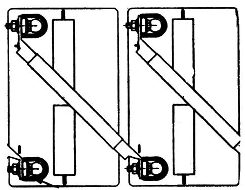
17 AQURE 8-INTERROW CABLED CONNECTIONS BETWEEN RACKS INSTALLED BACK TO BACK Figure 8-1-Typical Single Cable Interrow Connection for Batteries With.'L:' Terminals Figure 8-2-Typical Dual Cable Interrow Connection for Batteries With "Flag" Terminals Figure 8-3-Typical Single Cable Interrow Connection for Batteries With Threaded Insert Terminals 17

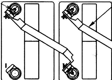
18 FIGURE 9-INTERRACK CONNECTIONS BETWEEN RACKS PLACED END TO END WITH 4" SPACING ~ Figure 9-1-Typical Single Cable Interrack Connection for Batteries With "L:' Terminals Figure 9-2 Figure 9-3-Typical Single Cable Interrack Connection for Batteries With Threaded Insert Terminals Figure 9-4-Typical Single Cable Interrack Connection for Batteries With Small "Flag" Terminals 18


. 2.")
19 Battery Connection to the Load I Charger Select the proper size and type of cable per the NEC or other applicable code which can handle the charge and discharge current related to the battery. The cable size selected should also consider the cable resistance per foot and the voltage drop allowed between the battery output terminals and the load. The output circuit of the battery should contain a DC rated fuse or circuit breaker to protect the wiring and where appropriate a disconnect to facilitate service to the battery in an open circuit condition. With the load/charger fuse, circuit breaker or disconnect in the "open" condition, connect the battery output cables to the load/charger circuit. Connection of Individual Battery Strings When individual strings of batteries are to be connected in parallel, each of the individual battery strings should be cabled separately to a common junction point or box. They should not be "daisy chained" in parallel. Each of the individual battery strings output circuits should contain a fuse, circuit breaker or disconnect prior to the common connection at the junction point to protect the wiring and facilitate battery maintenance. When the separate strings of batteries are to be initially connected in parallel their open circuit voltages should be within 1 VDC of each other prior to making the paralleling connection. Battery System Pre-Operational Checks Prior to application of any freshening charge or load to the battery system the following checks should be performed as defined in the pamphlet "Operational Qualification and Warranty Registration Checklist". Battery Room and General Equipment Checks 2. Battery Charger / Rectifier Checks, 3. Battery Rack/Enclosure Checks. 4. Battery Open Circuit Checks. Initial Freshening Charge When the batteries have been in storage or transit for an extended period or the battery system is intended for use at the minimum float charging voltage or when the number of cells in series is greater than 24, it is recommended the battery system be given a freshening charge at 2.4 volts average per cell for 24 hours. This will assure higher initial performance and will reduce the time period required for the cells to achieve proper voltage balance between the individual units. Document the progress of the freshening charge in Section V of the pamphlet "Operational Qualification and Warranty Checklist". To apply a freshening charge 1. Confirm the freshening (equalization) voltage from the charger / rectifier is set to a value equal to 2.4 volts per cell X number of cells connected in series (7.2 and 14.4 volts respectively for 6 volt and 12 volt batteries). 2. Close the circuit from the charger/rectifier to the battery system and note that the battery accepts current. 3. Monitor the battery periodically and note that the operation is proceeding normally and that the current acceptance is declining, the batteries are not overheating (within :!:5 F of each other and the ambient) and that the individual battery voltages on equalization charge are 7.2:!:0.25 and 14.4:!:0.50 volts for 6 and 12 volt batteries respectively. 4. Terminate the freshening charge in the event of any extraordinary situations or after 24 hours. Initial "Roat" Charging Following the "freshening" charge the battery system should be placed on "float" charge at an average voltage of 2.25 to 2.30 volts per cell (6.75 to 6.90 and 13.5 to 13.9 volts for 6 and 12 volt batteries respectively). Prior to placing on "float" charge, assure the charger/rectifier is set to the proper output voltage. 19


20 After the battery system has been on.'float" for approximately 24 hours, the float current acceptance should be approximately to.005 amperes or less per rated ampere hour capacity of the battery string but greater than zero. The individual battery float charging voltages should be within the following range: 12 volt batteries 13.3 min. to 14.5 max. 10 volt batteries min. to 12.1 max 6 volt batteries 6.65 min. to 7.25 max. 4 volt batteries 4.43 min. to 4.85 max. Document the results of these measurement activities in Section VI, Float Charging Checks, of the,'operational Qualification and Warranty Registration Checklist". If any special battery monitoring equipment is to be utilized, it should be installed and calibrated at this time. The DYNASTY battery system installation is now complete and the system is available for acceptance testing and operational service. Optional Battery Tests and Checks While not a requirement of the warranty registration the following checks are recommended to assure maximum reliability of the battery system over time. 1. "High rate momentary load" test as described in the pamphlet "Integrity Testing" # While this test does not indicate the actual capacity of the battery it does indicate it is functional. 2. Individual battery measurements of resistance/ conductance/impedance as described in the pamphlet "Impedance and Conductance Testing" # Again, while this test does not indicate the actual capacity of the battery it does provide base line data from which changes can be trended over time as the battery normally deteriorates. This can be very useful in trouble analysis during the periodic maintenance activities. 3. Battery performance test as described in the pamphlet "Acceptance and Performance Testing" #
VRLA Batteries. Battery Installation And Start up Guide
 TECHNICAL MANUAL 41-7525 VRLA Batteries 26-206 Ampere-Hour Capacity Battery Installation And Start up Guide (For Rack Mounted Systems) 41-7525/0514/CD www.cdtechno.com Table of Contents 12V VRLA Battery
C&D Technologies, Inc. Dynasty Division 900 East Keefe Avenue Milwaukee, WI53212 Phone: Fax:
 , C&D Technologies, Inc. Dynasty Division 900 East Keefe Avenue Milwaukee, WI53212 Phone: 800-396-2789 Fax: 414-961-6506 Form 41-7525 (Rev.6100) Printed in U.S.A. Inter-tier, Inter-Unit Inter-row Cables,
Installation and Operating Procedures For C&D Technologies TRUE Front Access TEL Series Batteries
 RS-2046 Installation and Operating Procedures For C&D Technologies TRUE Front Access TEL Series Batteries FOLLOW MANUFACTURER S PUBLISHED INSTRUCTIONS WHEN INSTALLING, CHARGING AND SERVICING BATTERIES.
Installation and Operating Procedures For C&D Technologies TRUE Front Access TEL Series Batteries
 RS02046 Installation and Operating Procedures For C&D Technologies TRUE Front Access TEL Series Batteries FOLLOW MANUFACTURER S PUBLISHED INSTRUCTIONS WHEN INSTALLING, CHARGING AND SERVICING BATTERIES.
Dual-Lite Trident TRF 40 Wide Battery Cabinet 20-40kVA Systems USER MANUAL
 Dual-Lite Trident TRF 40 Wide Battery Cabinet 20-40kVA Systems USER MANUAL 755-00020-DL 5/17/2017 2 755-00020-OEM R01 TABLE OF CONTENTS 1. Important Information About This Manual... 4 1.1 Manual Symbols...
TECHNICAL BULLETIN Fig #1 - VRLA Battery Components. Intercell Welded Connection Strap joining neg. plates in parallel.
 TECHNICAL BULLETIN 41-7264 IntegrIty testing The valve regulated lead acid (VRLA) battery has several components (Ref. Figure 1), all of which can deteriorate with storage conditions and normal as well
BR62 Battery Rack Installation, Operation, & Maintenance Manual
 BR62 Battery Rack Installation, Operation, & Maintenance Manual 8/28/2012 2 755-00046 R02 Copyright 2012 C&C Power, Inc. All rights reserved. C&C Power, Inc. 395 Mission Street Carol Stream, IL 60188 www.ccpower.com
FLUSH EYES IMMEDIATELY WITH WATER. GET MEDICAL HELP FAST. SULFURIC ACID CAN CAUSE BLINDNESS OR SEVERE BURNS.
 8A & 8G BATTERY INSTALLATION AND OPERATING INSTRUCTIONS This manual is intended to be a guide to optimize battery performance for multiple cyclic & float applications. Consult applicable User Manuals for
IEEE IAS Atlanta Chapter
 Stationary Battery Sizing IEEE IAS Atlanta Chapter Presented by: Lesley Varga, P.E. Quality Standby Services, LLC 1649 Sands Place, SE, Suite C Marietta, GA 30067 (770) 916-1747 lesley@qualitystandbyservices.com
INSTALLATION AND OPERATION MANUAL
 INSTALLATION AND OPERATION MANUAL California Proposition 65 Warning: Batteries, battery posts, terminals and related accessories contain lead and lead compounds, and other chemicals known to the state
Installation, Operation & Maintenance Manual DataSafe HX Front Terminal Battery Cabinets
 Installation, Operation & Maintenance Manual DataSafe HX Front Terminal Battery Cabinets Publication No. US-HXFTCAB-IM-001 This manual provides instructions regarding safety, storage, installation, operation
2 VOLT STATIONARY BATTERIES INSTALLATION
 2 VOLT STATIONARY BATTERIES INSTALLATION and OPERATION MANUAL TABLE OF CONTENTS SECTION CONTENT PAGE SECTION CONTENT PAGE 1.0 GENERAL INFORMATION 2 5.5 Electrical Connections 4 1.1 Battery Characteristics
HAZE 6/12 Volt. STATIONARY 6/12 Volt BATTERIES. HAZE Battery Co. INSTALLATION and OPERATING INSTRUCTIONS. Supplied Worldwide by :
 HAZE 6/12 Volt STATIONARY 6/12 Volt BATTERIES INSTALLATION and OPERATING INSTRUCTIONS Supplied Worldwide by : HAZE Battery Co. TABLE OF CONTENTS SECTION CONTENT PAGE SECTION CONTENT PAGE 1.0 GENERAL INFORMATION
POWER FOR TOMORROW. Motive Power. Network Power. Chargers. Bloc Batteries. Accessories. Service
 POWER FOR TOMORROW TODAY The Eternity Technologies range is built using only the highest quality and most efficient production processes at our state-of-the-art manufacturing centre in the UAE. It is this
Owner s Manual. Extended-Run Single-Phase Battery Cabinet. Not suitable for mobile applications.
 Warranty Registration: register online today for a chance to win a FREE Tripp Lite product www.tripplite.com/warranty Owner s Manual Extended-Run Single-Phase Battery Cabinet Not suitable for mobile applications.
Deep Cycle Battery Safety. First. Battery Handling, Maintenance & Test Procedures
 Deep Cycle Battery Safety. First. Battery Handling, Maintenance & Test Procedures Crown deep cycle batteries employ a low-maintenance design. They do require periodic maintenance and effective charging
INSTALLATION & OPERATING INSTRUCTIONS
 INSTALLATION & OPERATING INSTRUCTIONS SECTION 92.30 2016-09 INDEX Page Section 1 - GENERAL INFORMATION 1.0 Marathon/Sprinter/SUNlyte Batteries 1 Section 2 - SAFETY PRECAUTIONS 2.0 Safety Alert 1 2.1 Sulfuric
SOS SERIES SOS1 SOS2. Spares On Site Battery Cabinet Installation Guide rEV3
 Atlantic Battery Systems 1065 Market Street Paterson, NJ 07513 Phone: (800) 875-0073 Fax: (973) 523-2344 sales@atbatsys.com www.atbatsys.com SOS1 SOS2 SOS SERIES Spares On Site Battery Cabinet Installation
Motive Power. Network Power. Chargers. Bloc Batteries. Accessories. Service
 The Eternity Technologies range is built using only the highest quality and most efficient production processes at our state-of-the-art manufacturing centre in the UAE. It is this innovation, modern design
AGM Series. Installation Manual AGM Series Modular Battery Systems
 Installation Manual Modular Battery Systems Installation Manual Modular Battery Systems IMPORTANT! Read safety information first See Safety, Storage, Operating and Maintenance Manual The installation
Motive Power. Network Power. Chargers. Bloc Batteries. Accessories. Service
 The Eternity Technologies range is built using only the highest quality and most efficient production processes at our state-of-the-art manufacturing centre in the UAE. It is this innovation, modern design
Valve Regulated Lead Acid (VRLA) Battery Series Designed for UPS Standby Power Applications FEATURES & BENEFITS
 Battery Series Designed for UPS Standby Power Applications FEATURES & BENEFITS") 12-1079 HIGH RATE MAX UPS 12-355MRF APPLICATIONS Data Centers Network Operations Centers Industrial Process Control Facilities Internet Housing Sites Semiconductor Manufacturing Banks & Financial Markets
12-1079 HIGH RATE MAX UPS 12-355MRF APPLICATIONS Data Centers Network Operations Centers Industrial Process Control Facilities Internet Housing Sites Semiconductor Manufacturing Banks & Financial Markets
NB Module. Installation and Operation Manual. California Proposition 65 Warning:
 NB Module Installation and Operation Manual California Proposition 65 Warning: Batteries, battery posts, terminals and related accessories contain lead and lead compounds, and other chemicals known to
EnergyCell FLA Series. Owner s Manual
 Series Owner s Manual About OutBack Power Technologies OutBack Power Technologies is a leader in advanced energy conversion technology. OutBack products include true sine wave inverter/chargers, maximum
SENS DC PowerCab 120 Installation, Operation, & Maintenance Manual
 Installation, Operation, & Maintenance Manual Stored Energy Systems Packaged By: 1840 Industrial Circle C&C Power, Inc. Longmont, Co 80501 395 Mission Street www.sens-usa.com Carol Stream, IL 60188 Technical
INSTALLATION AND OPERATING INSTRUCTIONS FOR FLOODED TUBULAR-HP AND TUBULAR-LM FAST CHARGE MOTIVE POWER BATTERIES
 PLEASE READ THESE INSTRUCTIONS BEFORE PLACING BATTERIES INTO SERVICE. THESE INSTRUCTIONS MUST BE SHIPPED WITH THE BATTERY AND MUST BE DELIVERED TO THE USER. INSTALLATION AND OPERATING INSTRUCTIONS FOR
INSTALLATION AND OPERATING INSTRUCTIONS FOR FLOODED TUBULAR-HP MOTIVE POWER BATTERIES
 PLEASE READ BEFORE PLACING BATTERIES IN SERVICE THESE INSTRUCTIONS TO BE SHIPPED WITH BATTERY AND TO BE DELIVERED TO USER INSTALLATION AND OPERATING INSTRUCTIONS FOR FLOODED TUBULAR-HP MOTIVE POWER BATTERIES
PURE LEAD PLUS UPS APPLICATIONS Valve Regulated Lead Acid Battery Designed for UPS Standby Power Applications Watts per Cell
 -11 PURE LEAD PLUS Valve Regulated Lead Acid Battery Designed for UPS Standby Power Applications 305-545 Watts per Cell FEATURES & benefits APPLICATIONS Data Centers Network Operations Centers Industrial
INSTALLATION AND OPERATION INSTRUCTIONS
 INSTALLATION AND OPERATION INSTRUCTIONS Ref No: ARB- MAN-Quanta-13-001 This document details procedures to be followed while installing and operating AMARON QUANTA TM SMF-VRLA batteries. The procedures
Powerware Vdc Extended Battery Cabinet User s Guide.
 Powerware 9125 48 Vdc Extended Battery Cabinet User s Guide www.powerware.com FCC Part 15 Class A EMC Statements NOTE This equipment has been tested and found to comply with the limits for a Class A digital
A+ Battery Backup Power Supply For use with Hydromatic model B-A1/BV-A1
 Unit Installation and Service Manual A+ Battery Backup Power Supply For use with Hydromatic model B-A1/BV-A1 NOTE! To the installer: Please make sure you provide this manual to the owner of the pumping
MODEL A96 SERIES. 130Vdc Switchmode Utility Rectifier / Battery Charger. Used with LaMarche Power Cage ECN/DATE
 MODEL A96 SERIES 130Vdc Switchmode Utility Rectifier / Battery Charger Used with LaMarche Power Cage CPN112138 ECN/DATE ISSUE DATE: ECN 17010-12/05 106 BRADROCK DRIVE DES PLAINES, IL. 60018-1967 (847)
Owner s Manual Extended-Run Battery Cabinet
 Owner s Manual Extended-Run Battery Cabinet Models: BP240V370, BP240V370NB Not suitable for mobile applications. Este manual esta disponible en español en la página de Tripp Lite: www.tripplite.com Ce
Pump Sentry. Models 812 PS & 1612 PS INSTALLATION INSTRUCTIONS
 Pump Sentry Models 812 PS & 1612 PS INSTALLATION INSTRUCTIONS The Pump Sentry is an innovative power station designed to operate your pump during a power outage. When properly installed, it will provide
6/12 VOLT STATIONARY BATTERIES INSTALLATION and OPERATION MANUAL
 /1 VOLT STATIONARY BATTERIES INSTALLATION and OPERATION MANUAL TABLE OF CONTENTS SECTION CONTENT PAGE SECTION CONTENT PAGE 1.0 1.1.0.1..3. 3.0 3.1 3..0.1. GENERAL INFORMATION Battery Characteristics SAFETY
MODEL 6010A 6 12 VOLT BATTERY CHARGER ASSOCIATE
 MODEL 600A 6 VOLT BATTERY CHARGER ASSOCIATE IMPORTANT SAFETY INSTRUCTIONS. SAVE THESE INSTRUCTIONS. This manual contains important safety and operating instructions for the battery charger you have purchased.
INSTALLATION AND OPERATION MANUAL
 INSTALLATION AND OPERATION MANUAL TABLE OF CONTENTS SAFETY PRECAUTIONS Protective Equipment...3 Procedures...3 RECEIVING & STORAGE Receiving Inspection...3 Unpacking...3 Storage...4 INSTALLATION General...4
AUTO CHARGE D PUMP PLUS
 INSTRUCTION MANUAL AUTO CHARGE D PUMP PLUS AUTOMATIC DUAL OUTPUT BATTERY CHARGER Designed Specifically for Vehicles with DDEC ENGINES MODEL #: 091-9-DPP INPUT: 120 Volt, 60 Hz, 8 Amps OUTPUT VEHICLE BATTERY:
PURE LEAD PLUS UPS APPLICATIONS. Valve Regulated Lead Acid Battery Designed for UPS Standby Power Applications Watts per Cell
 UPS 12-1121 PURE LEAD PLUS Valve Regulated Lead Acid Battery Designed for UPS Standby Power Applications 305-545 Watts per APPLICATIONS Data Centers Network Operations Centers Industrial Process Control
Basic Battery Safety. Lead Acid Storage Batteries
 Basic Battery Safety Lead Acid Storage Batteries Hazards of Lead Acid Batteries Chemical burns (sulfuric acid) Arc flash / burns Shock Explosive gas (hydrogen) Fire Weight Sulfuric Acid Safety PPE requirements
10 AMP ON BOARD BATTERY CHARGER
 R A Valley Forge Company MODEL 2611A-1-B 10 AMP ON BOARD BATTERY CHARGER One Output OWNER S MANUAL IMPORTANT! READ THESE INSTRUCTIONS BEFORE INSTALLING AND USING THIS PRODUCT. Keep these instructions for
AUTO CHARGE D2 MODEL #: AUTOMATIC TRIPLE OUTPUT BATTERY CHARGER INSTRUCTION MANUAL
 INSTRUCTION MANUAL AUTO CHARGE D2 AUTOMATIC TRIPLE OUTPUT BATTERY CHARGER Designed Specifically for Vehicles with DDEC ENGINES MODEL #: 091-74-12 INPUT: 120 Volt, 60 Hz, 8 Amps OUTPUT VEHICLE BATTERY 1
IMPORTANT SAFETY INSTRUCTIONS
 ASSOCIATED Model 6039 Battery Tester Operator's Manual IMPORTANT SAFETY INSTRUCTIONS 1. SAVE THESE INSTRUCTIONS This manual contains important safety and operating instructions for the battery tester you
FIAMM Industrial Batteries December 2012 FIAMM AGM Valve Regulated Recombination Batteries: FLX Series- Engineering Manual TABLE OF CONTENTS
 TABLE OF CONTENTS PAGE 1 OPERATING CHARACTERISTICS 2 2 INSTALLATION 4 3 CHARGING 6 4 STORAGE AND REFRESH CHARGING 8 5 MAINTENANCE AND TESTING 9 6 SAFETY 10 7 APPLICABLE STANDARDS 10 8 RECORDS DATA 10 FIAMM.
PAC 600 PAC 800 PAC 800 comfort
 PAC 600 PAC 800 PAC 800 comfort Installation and User Manual Advanced Battery Chargers Table of contents POWERFINN PAC 600/800...2 General... 2 Installation...3 Operations... 4 Safety Instructions... 5
Cruising Charger Series OWNER S MANUAL
 R Cruising Charger Series OWNER S MANUAL ON BOARD BATTERY CHARGERS Models DC Amperage No. Of Banks Volts 2614A 5,10 Amps 2 Bank 12/12 2614A-230 2621A 5,5,10 Amps 3 Banks 12/12/12 2621A-230 2622A 10,10
AUTO CHARGE 4000 MODEL #: LOW PROFILE CHARGER AUTOMATIC DUAL OUTPUT BATTERY CHARGER INSTRUCTION MANUAL
 INSTRUCTION MANUAL AUTO CHARGE 4000 LOW PROFILE CHARGER AUTOMATIC DUAL OUTPUT BATTERY CHARGER Unit supplied with this display MODEL #: 091-89-12 INPUT: 120 Volt, 50/60 Hz, 5 Amps OUTPUT: 45 Amps File:
PSJ-2212, PSJ-3612, PSJ-4424
 Model: PSJ-2212, PSJ-3612, PSJ-4424 Jump Starter and DC Power Source OWNER S MANUAL PSJ-2212 PLEASE SAVE THIS OWNER S MANUAL AND READ BEFORE EACH USE. This manual will explain how to use your jump starter
Installation And Operation Instructions
 Installation And Operation Instructions For PS Series Mini-Inverter Power Systems Models: PS-55-LP, PS-110-HP, PS-110-LP, PS-220-HP Surface (-S), Recessed (-R) and Ceiling T-Grid (-T) Mounted Versions
Installation And Operation Instructions
 Installation And Operation Instructions For MPS Series Micro-Inverter Power Sytems Lead Calcium Battery Models: MPS-32 and MPS-55 Nickel Cadmium Battery Models: MPS-20 and MPS-35 Surface (-S), Recessed
MODEL ELC-12/40-CVM-D BATTERY CHARGER
 NATIONAL RAILWAY SUPPLY MODEL ELC-12/40-CVM-D BATTERY CHARGER Installing, Operating and Service Instructions for the ELC-12/40-CVM-D Solid State Charger PLEASE SAVE THESE IMPORTANT SAFETY AND OPERATING
RS Valve Regulated Lead-Acid Batteries
 P o w e r S o l u t i o n s RS-1991 Valve Regulated Lead-Acid Batteries SAFETY PRECAUTIONS Only authorized and trained personnel familiar with battery installation, preparation, charging, and maintenance
Dimensions 12/800N 12/1200N D. DC to AC Power Inverters. OWNERS MANUAL for Models: OWNERS MANUAL April ISO 9001:2000 Certified Company
 Manufacturer of Dimensions Inverters 4467 White Bear Parkway St. Paul, MN 55110 Phone: 651-653-7000 Fax: 651-653-7600 E-mail: inverterinfo@sensata.com Web: www.dimensions.sensata.com OWNERS MANUAL April
SCC-MPPT Solar Charge Controller
 Solar Charge Controller Quick Guide 200W 300W 400W 600W 850W V. 2.2 1. Introduction solar charge controller uses PWM-based DSP controller to keep the batteries regulated and prevent batteries from overcharging
BATTERY SAVER LOW RIPPLE HO
 INSTRUCTION MANUAL BATTERY SAVER LOW RIPPLE HO LOW RIPPLE POWER SUPPLY / AUTOMATIC LOAD SWITCH FOR 12VDC VEHICLE SYSTEMS MODEL #: 091-195-12 INPUT: 120 Volt, 50/60 Hz, 4.5 Amps RMS OUTPUT: 13.2 Volts DC,
MODEL A97 SERIES. Switchmode Utility Rectifier/Battery Charger ECN/DATE
 MODEL A97 SERIES Switchmode Utility Rectifier/Battery Charger CPN108172 ISSUE DATE: 16071 7/03 ECN/DATE 106 BRADROCK DRIVE DES PLAINES, IL. 60018-1967 (847) 299-1188 FAX: (847)299-3061 Page 1 of 7 INSTRUCTION
AUTO CHARGE 11 MODEL #: XX. AUTOMATIC BATTERY CHARGER U.L. Configuration INSTRUCTION MANUAL
 INSTRUCTION MANUAL AUTO CHARGE 11 AUTOMATIC BATTERY CHARGER U.L. Configuration MODEL #: 091-11-XX NOTE : This charger is designed for vehicles with dual batteries and negative ground. CAUTION This unit
ADI-125/750 ADI-125/1500 ADI-125/2500
 Manufacturer of Dimensions TM Inverters 4467 White Bear Parkway St. Paul, MN 55110 Phone: 651-653-7000 Fax: 651-653-7600 E-mail: inverterinfo@sensata.com Web: www.dimensions.sensata.com 121094B OWNERS
AUTO CHARGE 12 AUTOMATIC BATTERY CHARGER
 INSTRUCTION MANUAL FILE: 091-165-12 reve Rev: E, page 8 DATE: 7-02-15 AUTO CHARGE 12 AUTOMATIC BATTERY CHARGER MODEL #091-165-12 NOTE : This charger is designed for vehicles with a single battery and negative
High Frequency SineWave Guardian TM
 High Frequency SineWave Guardian TM 380V 480V INSTALLATION GUIDE FORM: SHF-IG-E REL. January 2018 REV. 002 2018 MTE Corporation High Voltage! Only a qualified electrician can carry out the electrical installation
Smart Charger 12-24V 60A, 1600W
 Smart Charger 12-24V 60A, 1600W Installation and User Manual Advanced Battery Chargers Table of contents Important SC 60A General SC60A 2 General 2 Installation 3 Operations 4 Safety Instructions 5 Troubleshooting
TECHNICAL MANUAL RS02061
 TECHNICAL MANUAL RS02061 Standby Batteries for Renewable Energy Applications Installation and Operating Instructions RS02061/0514/CD www.cdtechno.com Table of Contents Table of Contents 2 SAFETY PRECAUTIONS
SUBSTATION EQUIPMENT - Page 1 of 8
 BATTERY BANKS 1. GENERAL: JEA utilizes a 125 volt DC system for the control and operation of its transmission and distribution substations. JEA has standardized on lead acid type battery banks to supply
SCC-MPPT Solar Charge Controller
 Table 3: Charging voltage for 4 types of battery Battery Battery 12V battery system 24V battery system Type Type Code Bulk Floating Bulk Floating Vented 01 14.3 V 13.2 V 28.6 V 26.4 V Sealed 02 14.3 V
OPERATOR'S MANUAL IMPORTANT SAFETY INSTRUCTIONS
 ASSOCIATED OPERATOR'S MANUAL IMPORTANT SAFETY INSTRUCTIONS MODEL 6366 12 VOLT, 0-20 AMP 4 X 20 BATTERY CHARGER 1. SAVE THESE INSTRUCTIONS. This manual contains important safety and operating instructions
Installation and Operation Instructions SERVICE BY QUALIFIED PERSONNEL ONLY
 ELI-S-600 120 Volt ELI SERIES EMERGENCY LIGHTING INVERTERS Installation and Operation Instructions! IMPORTANT SAFEGUARDS! WHEN USING ELECTRICAL EQUIPMENT, BASIC SAFETY PRECAUTIONS SHOULD ALWAYS BE FOLLOWED,
A48 / A48B (base plate) BATTERY CHARGER
 BATTERY CHARGER") A48 / A48B (base plate) BATTERY CHARGER CPN41054 ISSUE DATE: 12315-8/98 ECN/DATE 106 BRADROCK DRIVE DES PLAINES, IL. 60018-1967 (847) 299-1188 FAX: (847)299-3061 15349-07-07/02 16041 6/03 14575-2/01 INSTRUCTION
A48 / A48B (base plate) BATTERY CHARGER CPN41054 ISSUE DATE: 12315-8/98 ECN/DATE 106 BRADROCK DRIVE DES PLAINES, IL. 60018-1967 (847) 299-1188 FAX: (847)299-3061 15349-07-07/02 16041 6/03 14575-2/01 INSTRUCTION
Solar Charge Controller
 Table 3: Charging voltage for 4 types of battery Battery Type Battery Type Code SC-600W MPPT Bulk Voltage Floating Voltage Vented 01 28.6 V 26.4 V Sealed 02 28.6 V 26.8 V Gel 03 28.6 V 27.4 V NiCd 04 28.6
Today, we re going to talk about battery safety. We ll discuss all the key issues associated with using batteries safely, including battery hazards,
 Today, we re going to talk about battery safety. We ll discuss all the key issues associated with using batteries safely, including battery hazards, battery charging, and battery maintenance. Although
OWNERS MANUAL JANUARY 2007 ISO
 Manufacturer of Dimensions TM Inverters 4467 White Bear Parkway St. Paul, MN 55110 Phone: 651-653-7000 Fax: 651-653-7600 E-mail: inverterinfo@sensata.com Web: www.dimensions.sensata.com 121231B OWNERS
AUTO CHARGE 4000 MODEL #: AUTOMATIC DUAL OUTPUT BATTERY CHARGER INSTRUCTION MANUAL. Ph: Fax:
 INSTRUCTION MANUAL AUTO CHARGE 4000 AUTOMATIC DUAL OUTPUT BATTERY CHARGER MODEL #: 091-89-12 INPUT: 120 Volt, 50/60 Hz, 8 Amps OUTPUT BATTERY CHARGER: 40 Amps OUTPUT BATTERY SAVER: 5 Amps File: IM_091-89-12_reve.indd
dv Sentry TM 208V 600V INSTALLATION GUIDE Quick Reference ❶ How to Install Pages 6 14 ❷ Startup/Troubleshooting Pages WARNING
 dv Sentry TM 208V 600V INSTALLATION GUIDE FORM: DVS-IG-E REL. January 2018 REV. 003 2018 MTE Corporation High Voltage! Only a qualified electrician can carry out the electrical installation of this filter.
Mitsubishi Electric Power Products, Inc. BC55 Battery Cabinet Installation, Operation, & Maintenance Manual
 Mitsubishi Electric Power Products, Inc. BC55 Battery Cabinet Installation, Operation, & Maintenance Manual Built for Mitsubishi Electric Power Products, Inc. by 5/30/2014 2 755-00041 R08 This manual contains
SCC-MPPT Solar Charge Controller
 Table 4: Alarm point for low battery voltage table Model Alarm point SCC-MPPT-300 10.5 V SCC-MPPT-600 21.0 V Table 5: Charging hour table for reference Battery Capacity To 90% capacity @ 25A charging current
model ps600 Address all communications and shipments to: FEDERAL SIGNAL CORPORATION
 MODEL: PS600 HZ: 60 A model ps600 installation and service manual for federal model ps600 FEDERAL SIGNAL CORPORATION POWER SUPPLY VOLTS: SERIES: 120VAC FEDERAL SIGNAL CORPORATION UNIVERSITY PARK, IL. U.S.A.
OWNER S MANUAL. Model YUA2AMPCH 2 AMP Dual-Bank Automatic Battery Charger & Maintainer READ ENTIRE MANUAL BEFORE USING THIS PRODUCT
 Model YUA2AMPCH 2 AMP Dual-Bank Automatic Battery Charger & Maintainer Certified by California BCS Regulations OWNER S MANUAL READ ENTIRE MANUAL BEFORE USING THIS PRODUCT READ ENTIRE MANUAL BEFORE USING
LPC 20 MODEL #: LOW PROFILE CHARGER AUTOMATIC SINGLE OUTPUT BATTERY CHARGER INSTRUCTION MANUAL
 INSTRUCTION MANUAL LPC 20 LOW PROFILE CHARGER AUTOMATIC SINGLE OUTPUT BATTERY CHARGER Unit supplied with one of these displays MODEL #: 091-207-12 INPUT: 120 Volt, 50/60 Hz, 7 Amps OUTPUT: 20 Amps File:
AUTO CHARGE DUAL MODEL #: AUTOMATIC DUAL OUTPUT BATTERY CHARGER INSTRUCTION MANUAL. Ph: Fax:
 INSTRUCTION MANUAL AUTO CHARGE DUAL AUTOMATIC DUAL OUTPUT BATTERY CHARGER MODEL #: 091-145-12 INPUT: 120 Volt, 50/60 Hz, 3.5 Amps OUTPUT BAT 1: 10 Amps OUTPUT BAT 2: 10 Amps File: IM_091-145-12_revb.indd
Installation Instructions and User Manual For. 100 Watt Inverter Power System
 Installation Instructions and User Manual For 100 Watt Inverter Power System Installation Instructions and User Manual For LiteGear 100 Watt Inverter Power System Warning: THIS PRODUCT CONTAINS CHEMICALS
PUMP PLUS 1000 PLC MODEL #: PP AUTOMATIC SINGLE OUTPUT BATTERY CHARGER INSTRUCTION MANUAL
 INSTRUCTION MANUAL PUMP PLUS 1000 PLC AUTOMATIC SINGLE OUTPUT BATTERY CHARGER Unit supplied with one of these displays MODEL #: 091-215-12-PP INPUT: 120 Volt, 60 Hz, 3.5 Amps OUTPUT BATTERY 1 and 2: 15
PUMP PLUS 2000 PLC MODEL #: PP AUTOMATIC DUAL OUTPUT BATTERY CHARGER INSTRUCTION MANUAL
 INSTRUCTION MANUAL PUMP PLUS 2000 PLC AUTOMATIC DUAL OUTPUT BATTERY CHARGER Supplied with Dual Bar Graph Display MODEL #: 091-237-12-PP INPUT: 120 Volt, 60 Hz, 3.5 Amps OUTPUT BATTERY 1 and 2: 15 or 18
www. ElectricalPartManuals. com TOSHIBA 1600EP SERIES MANUFACTURED IN THE U.S.A. OPERATION MANUAL BATTERY CABINET SYSTEM SINGLE PHASE- 8/10/14/18 kva
 August 2003 Part# 55416-000 TOSHIBA BATTERY CABINET SYSTEM SINGLE PHASE- 8/10/14/18 kva 1600EP SERIES MANUFACTURED IN THE U.S.A. OPERATION MANUAL 1600EP SERIES SINGLE PHASE- 8/10/14/18 kva BATTERY CABINET
Installation And Operation Instructions
 Installation And Operation Instructions For LPS Series Micro Inverter Power Systems Lead Calcium Battery Models: LPS32 and LPS55 Nickel Cadmium Battery Models: LPS20 and LPS35 Surface (-S), Recessed (-R)
Chapter 6. Batteries. Types and Characteristics Functions and Features Specifications and Ratings Jim Dunlop Solar
 Chapter 6 Batteries Types and Characteristics Functions and Features Specifications and Ratings 2012 Jim Dunlop Solar Overview Describing why batteries are used in PV systems. Identifying the basic components
OPERATOR S MANUAL JUMP STARTER. and DC Power Source. Model No CAUTION: Sears, Roebuck and Co., Hoffman Estates, IL U.S.A.
 OPERATOR S MANUAL JUMP STARTER and DC Power Source Model No. 71489 CAUTION: Read and follow all Safety Rules and Operating Instructions before Every Use of this Product. SAVE THESE INSTRUCTIONS. Sears,
MIL-24/2600Q MIL-24/3200DQ
 Manufacturer of Dimensions TM Inverters 4467 White Bear Parkway St. Paul, MN 55110 Phone: 651-653-7000 Fax: 651-653-7600 E-mail: inverterinfo@sensata.com Web: www.dimensions.sensata.com 121473B OWNER'S
Sentry Battery Charger. Installation and Operations Manual Section 75
 Sentry Battery Charger Installation and Operations Manual 00-02-0616 03-03-08 Section 75 In order to consistently bring you the highest quality, full featured products, we reserve the right to change our
Automatic Battery Charger Switching mode with Micro-controlled Input: Vac / Output: 12Volt DC
 Automatic Battery Charger Switching mode with Micro-controlled Input:220-260Vac / Output: 12Volt DC User s Manual and Important Safety Information Model: OC-SW121080 / OC-SW121160 / OC-SW121210 FEATURES
OBE, OBEXU, ON BOARD Battery Chargers
 C O R P O R A T IO N O P E R A T I N G I N S T R U C T I O N S OBE, OBEXU, ON BOARD Battery Chargers INTRODUCTION: These chargers are designed for the permanent installation on battery powered vehicles
LPC 40 MODEL #: LOW PROFILE CHARGER WITH PLC AUTOMATIC SINGLE OUTPUT BATTERY CHARGER INSTRUCTION MANUAL
 INSTRUCTION MANUAL LPC 40 LOW PROFILE CHARGER WITH PLC AUTOMATIC SINGLE OUTPUT BATTERY CHARGER Unit supplied with one of these displays MODEL #: 091-200-12 INPUT: 120 Volt, 50/60 Hz, 5 Amps OUTPUT: 40
Installation and Operating Instructions for Monolite. Valve-Regulated Lead Acid Batteries
 Installation and Operating Instructions for Monolite Valve-Regulated Lead Acid Batteries Important Note Monolite batteries must be placed on charge within 6 months from date of shipment. Failure to observe
OBAE, OBAEXU, ON BOARD Battery Chargers
 C O R P O R A T IO N O P E R A T I N G I N S T R U C T I O N S OBAE, OBAEXU, ON BOARD Battery Chargers INTRODUCTION: The OBAE line of chargers are designed for the permanent installation on battery powered
MODEL ELC-12/60-D BATTERY CHARGER
 *32198* NATIONAL RAILWAY SUPPLY Installing, Operating and Service Instructions for the 12/60 Solid State Charger MODEL ELC-12/60-D BATTERY CHARGER PLEASE SAVE THESE IMPORTANT SAFETY AND OPERATING INSTRUCTIONS
INSTALLATION, OPERATING & MAINTENANCE INSTRUCTIONS For Valve Regulated Lead Acid Batteries used in Stationary Applications
 INSTALLATION, OPERATING & MAINTENANCE INSTRUCTIONS For Valve Regulated Lead Acid Batteries used in Stationary Applications Commissioning by:... Date:... Number of cells/blocks:... Model #:... SAFETY PRECAUTIONS
Automatic Battery Charger Switching mode with Micro-controlled Input: Vac / Output: 12Volt DC
 Automatic Battery Charger Switching mode with Micro-controlled Input:220-260Vac / Output: 12Volt DC User s Manual and Important Safety Information Model: OC-SW121080 / OC-SW121160 / OC-SW121210 FEATURES
Battery Enclosure Installation Instructions
 MNBE-C Battery Enclosure Instructions Battery Enclosure Installation Instructions MNBE-C These instructions are for the installation of Midnite Solar Battery Enclosure models MNBE-C, MNBE-CL16 and MNBE-C8D
Installation and Operating Instructions. Solar System Controller ISC3020
 Installation and Operating Instructions Solar System Controller ISC3020 ABOUT THIS MANUAL These operating instructions come with the product and should be kept with it as a reference to all user s of
AUTO CHARGE 12 HO MODEL #: MODEL #: MODEL #: AUTOMATIC SINGLE OUTPUT BATTERY CHARGER INSTRUCTION MANUAL
 INSTRUCTION MANUAL AUTO CHARGE 12 HO AUTOMATIC SINGLE OUTPUT BATTERY CHARGER MODEL #: 091-170-6 MODEL #: 091-170-12 MODEL #: 091-170-24 File: IM_091-170-xx_revd.indd Rev: D Revised By: MFG Date: 10-23-2013
LMI Watt Models
 LMI 300-600 Watt Models Service Questions Call: 800-451-9423 INSTALLATION AND OPERATING INSTRUCTIONS IMPORTANT SAFEGUARDS When using electrical equipment, basic safety precautions should always be followed,
FEATURES & benefits. Constant Power Discharge Ratings - Watts per 77 F (25 F) Operating Time (in minutes) to 1.
 Operating Time (in minutes) to 1.") -1029 Valve Regulated Lead Acid Battery Designed for UPS Standby Power Applications. APPLICATIONS Data Centers Network Operations Centers Industrial Process Control Facilities Internet Housing Sites Semiconductor
-1029 Valve Regulated Lead Acid Battery Designed for UPS Standby Power Applications. APPLICATIONS Data Centers Network Operations Centers Industrial Process Control Facilities Internet Housing Sites Semiconductor