CraftSmart Test Access Point (TAP) Box Installation Manual
|
|
|
- Abner Burke
- 5 years ago
- Views:
Transcription

1 Installation Manual
2 Installation Manual Table of Contents Application 3 Description 3 Technical Specifications 3 TAP Box Assembly 4 TAP Box Mounting 8 Cable Entrance 10 Grounding 11 Strength Member Clamp 11 Cable Routing 12 Connector Cleaning Procedure 13 Standard Warranty 16 Proprietary Notice 17 Technical Support 17 2

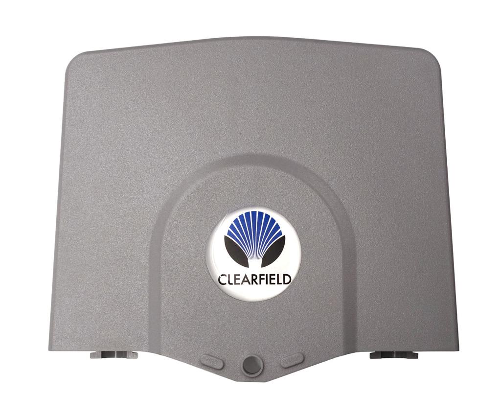
3 Installation Manual Application The CraftSmart Test Access Point (TAP) Box gives the service provider an accessible exterior access point to test fiber integrity before it enters the customer premise. This solution allows the service provider the ability to identify potential issues in conductivity from outside of the customer premise location. Description The CraftSmart TAP Box is a two part closure that will accommodate up to four fibers for test and access purposes. The base of the unit will allow up to four splices from the feeder cable to individual drops into the customer premise. Duplex SC adapters allow for installation of pre-terminated or field terminated fiber to be connectorized for test and access of the fiber - to determine feeder and drop issues. Two grommeted in/out ports on the bottom of the unit provide easy installation of both feeder and drop cables. The unit is lockable to minimize customer tampering. There are grounding options available inside the TAP Box that will allow grounding of the feeder and drop cables. It also has built in access to exterior grounding built into the unit. Multiple mounting options are available to meet all applications. The TAP box is available with private labeling on the front cover to easily identify service provider s identification. Technical Specifications CraftSmart Test Access Point (TAP) Box Dimensions Connector Availability/ Capacity Cable Support and Tie Off Options Splice Capacity Cable Entrance/Exit Private Labeling Pre-terminated Feeder and Drop Cable Mounting Options 7.3 H x 8.57 W x 1.67 D Empty: No connector One dual SC/APC or SC/UPC; two dual SC/APC or SC/UPC; quad LC/UPC or LC/APC; two quad LC/UPC or LC/APC Not included with TAP Box - MUST BE ORDERED SEPARATELY. TAP-GL-KIT (one clamp per kit) Strength member tie off kit for flat drop and dielectric cable TAP-ARM-GL-KIT (one clamp per kit) Ground lug bracket for armored cable - no strength member tie off Four One on each port (two total). If using FieldShield Microduct, order one FS-CPLR-10MM-10MM-TAP per exit Standard: comes with Clearfield logo. Private labeling available (500 piece minimum). Contact Clearfield sales representative for details Available: Please contact your Clearfield sales representative Wall Mount: Standard Vinyl Siding Mount: TAP-VS-KIT Pole Mount: TAP-PM-KIT 3


4 Installation Manual TAP Box Assembly 1. The Tap Box will arrive as shown. Remove the cover by sliding it off. Small parts will be contained inside, set them aside. 2. TAP Box will appear as shown. You will need a side cutters or pair of snips to remove the molded plastic pieces attached at the base of the box. Clip at the spots highlighted. 3. Proceed to clipping the pieces from the molding spur. Pieces should include: 1. Large cable management retainers (Qty 4) 2. Duplex SC adapter holder 3. Bridge lances/cable tie downs (Qty 2) 4. Small cable management retainers (Qty 4)

 into the top")


5 Installation Manual 4. Install the 4 large cable management retainers (round peg) into the top outside posts. 5. Install the 4 small cable management retainers (square peg) into the lower inside posts. 5

 into place inside the TAP Box.")


6 Installation Manual 6. Using the supplied VHB tape, secure the two cable tie downs (bridge lances) into place inside the TAP Box. Tie down locations exist above and below the splicing area. These will be used to secure the cable before splicing. 7. Snap the splice tray cover into place. If you plan to splice inside the TAP Box later, the cover will protect the splices. 6


7 Installation Manual 8. Place the adpater into the holder, and install it into the TAP Box at the top. Note: If you are not utilizing the lower adapter slot of the holder you may clip the piece to provide a path for cable to run underneath. 9. Trim the black cable entrance plugs, separating them. Place them into the entrances of the TAP Box. These can be used to provide a weather seal around the cable. If utilizing microduct and a coupler (P/N FS-CPLR-10MM-10MM-TAP) to bring cable into the TAP these may not be used. 7


8 Installation Manual TAP Box Mounting Wall Mount The TAP Box can be mounted to a wall using standard hardware and the provided holes Mounting holes Vinyl Siding Mount Siding clips (P/N TAP-VS-KIT) will be attached to the TAP Box with 2 barbed push fasteners per clip. TAP can then be hung from siding. 8
 can be attached to many")


9 Installation Manual Pole Mount The Pole Mount Bracket (P/N TAP-PM-KIT) can be attached to many different types of surfaces. Once attached, the TAP box can be secured to the bracket with normal hardware and the 4 provided mounting holes. 4 x 4 Post Sign Post Tube Clamp - 3 Pipe U-Bolt - 3 Pipe 9

 below the plug and secure it into place on the TAP Box with a zip tie.")
10 Installation Manual Cable Entrance The TAP Box accepts a pushable fiber quick connect coupler. The coupler can be zip tied into place and duct inserted into the coupler. Cable can then be fed through the duct and into the TAP Box. If not utilizing a coupler, cut two perpendicular slits in the center of the black cable entrance plug, and feed the cable through the plug. Then wrap the cable with grommet tape (foam tape) below the plug and secure it into place on the TAP Box with a zip tie. Insert the plug into place on the TAP just above. 10
11 Installation Manual Grounding If utilizing armored cable, an optional ground lug bracket for armored cable is available (P/N TAP-ARM-GL-KIT). Ground per your local rules and practices Strength Member Clamp For dielectric cable and flat drop cables, a strength member clamp can be used (P/N TAP-GL-KIT). 11
12 Installation Manual Cable Routing Radius protected slack management allows cable to be safely stored as it transitions from the entry to the mating point A cable exit is located at the bottom of the TAP Box which provides covered access to the inside of the building the box is mounted to. Cable tie downs, attached via VHB tape, can be used to secure the fiber prior to splicing. The TAP can be secured with either a lock or a security tab through the hole at the front of the box. 12


13 Installation Manual Connector Cleaning Procedure Whether factory terminated or field spliced, clean connectors are essential for proper system operation. Even the smallest dust particle can cause transmission problems, so for optimal network performance inspect, and if necessary, clean connectors and adapters prior to mating. Inspect Then Connect These are Clearfield recommended products/applications. Use the product you feel will complete your cleaning procedures. Create a best practice for your company and follow those procedures. The use of Chemtronics end face and bulkhead cleaning products and techniques ensures a clean end face, no matter the type of contamination. Before cleaning any connector, be sure you know what type of contaminate you are cleaning (dry, fluidic, or combination). All the available products are good, it s the process that you need to be aware of. Using a dry cleaning method to clean dirt can lead to scratching of the end face. Learn the process of cleaning properly. Figure 1 Note: It is NOT recommended to use isopropyl alcohol to clean the end face. Cleaning an SC/LC Connector Cleaning the End Face Place one wiping paper on QbE-2 FiberSafe Cleaning Platen. (Figure 1) Apply small amount of precision cleaner (about 1 in diameter) with Electro-Wash MX pen on to one end of the wipe. (Figure 2) Figure 2 Hold end face at a 90 degree angle. For APC connection, adjust by slightly tilting the container or end face. Angle is correct when no drag is felt on the end face. (Figure 3) Draw end face from wet to dry part of the wipe 3 times. Use just enough pressure to ensure complete contact between end face and the wipe. Note: DO NOT retrace previous step. Figure 3 13
 by spotting a small amount (about 1 ) of Electro-Wash PX or Electro-Wash MX pen onto the QbE. Hold the swab, 1 side down to the wetted area and hold for a count of 1-2-3-4-5.")
 Cleaning the Mate Through an Adapter AND the Adapter Itself Figure 5 Lightly moisten the fiber optic swab (2.5mm/38542F or 1.")

14 Installation Manual Cleaning the Ferrule Lightly moisten the fiber optic swab (2.5mm/38542F or 1.25mm/38040) by spotting a small amount (about 1 ) of Electro-Wash PX or Electro-Wash MX pen onto the QbE. Hold the swab, 1 side down to the wetted area and hold for a count of (Figure 4) Figure 4 Insert swab into side of ferrule, wet side to the ceramic ferrule and circle around 2-3 times and remove. Turn swab to dry side and repeat. (Figure 5) Cleaning the Mate Through an Adapter AND the Adapter Itself Figure 5 Lightly moisten the fiber optic swab (2.5mm/38542F or 1.25mm/38040) by spotting a small amount (about 1 ) of Electro-Wash PX or Electro-Wash MX pen onto the QbE. Hold the tip of the swab onto the wetted area and hold for a count of Insert the swab into the adapter to the connector, press lightly against the connector, twist 2-3 times, remove and discard. Dry with a second dry swab. Inspect, repeat cleaning if necessary, and test for signal strength. Use additional swabs to clean inside the actual adapter. Moisten swab, like above, and insert through hole and remove while twisting. (Figure 6) Figure 6 14
 Figure 1 Hold end face at a 90 degree angle. For APC connection, adjust by slightly tilting the container or end face.")
 Male Connector Figure 2 Lightly moisten one side of the fiber optic swab (CC505F) by spotting a small amount (about 1 ) of Electro-Wash PX or Electro-Wash MX pen onto the QbE.")
15 Installation Manual Cleaning an MPO/MTP Connector Female Connector Place one wiping paper on QbE-2 FiberSafe Cleaning Platen and apply small amount of precision cleaner (about 1 in diameter) with Electro-Wash MX pen on to one end of the wipe. (Figure 1) Figure 1 Hold end face at a 90 degree angle. For APC connection, adjust by slightly tilting the container or end face. Angle is correct when no drag is felt on the end face. (Figure 2) Male Connector Figure 2 Lightly moisten one side of the fiber optic swab (CC505F) by spotting a small amount (about 1 ) of Electro-Wash PX or Electro-Wash MX pen onto the QbE. Hold the swab, 1 side down to the wetted area and hold for a count of Place swab, wet side down, at one end of connector end face and draw across in a diagonal sweep; i.e., from fiber 1 up and across to fiber 12. Turn swab over to dry and draw back from fiber 12 to fiber 1. (Figure 3) Figure 3 15
16 Installation Manual Standard Warranty Clearfield warrants to the original purchaser of the Product sold hereunder is free from defects in material and workmanship under normal use and service, subject to exceptions stated herein. Product purchased is warranted as follows: Clearfield designed and branded Products are warranted for three (3) years: Products manufactured by Clearfield to customer prints and/or specifications are warranted for one (1) year; and any Product Clearfield acquires from or through a third-party manufacturer or distributor and resells to Customer as the original customer will carry the manufacturer s pass-through warranty, if any. In all cases, the warranty period commences on the date of shipment to the original purchaser. Warranty Claim Procedure If any Product purchased from Clearfield is found defective under the above warranty, the following basic procedure must be followed: 1. Customer must contact Clearfield and obtain a Return Materials Authorization 2. Following authorization, the Customer ships the product-freight collect-to Clearfield s manufacturing facility 3. Clearfield shall repair or replace the defective Product at its sole option and discretion, and return the repaired or replacement Product to Customer s site, freight prepaid Note: If the Product is not found to be defective by Clearfield, the product will be returned to the Customer and the customer billed for freight in both directions. View our warranty policy here: Limitations of Warranty Correction of defects by repair or replacement, at the option of Clearfield Inc, shall constitute the exclusive sole remedy for a breach of this limited warranty. Clearfield shall not be liable under any circumstances for any special, consequential, incidental, punitive, or exemplary damages arising out of or in any way connected with the product or with agreement to sell product to buyer, including, but not limited to damages for lost profits, loss of use, or for any damages or sums paid by buyer to third parties. The foregoing limitation of liability shall apply whether the claim is based upon principles of contract, warranty, negligence or other tort, breach of statutory duty, principles of indemnity or contribution, the failure of any limited or exclusive remedy to achieve its essential purpose, or otherwise. Clearfield will not be responsible for any labor or materials costs associated with installation or incorporation of Clearfield products at customer sites, including any costs of alteration, replacement or defective product, or any field repairs. Other Limitations Clearfield assumes no warranty liability regarding defects caused by: 1. Customer s modification of Product, excepting installation activities described in Clearfield documentation 2. Customer re-packaging of Product for shipment to third parties or destinations other than those originally shipped to by Clearfield, or any defects suffered during shipping where the Product has been re-packaged 3. Customer s installation or maintenance, excepting activities described in and performed in accordance with Clearfield documentation 4. Customer s improper or negligent use or application of Product 5. Other causes external to the Product, including but not limited to accidents, catastrophe, acts of God, government action, war, riot, strikes, civil commotion, sovereign conduct, or the acts or conduct of any person or persons not party to or associated with Clearfield 6. Environmental factors and weathering resulting in aging and damage not necessary or applicable to the function of the product 16
17 Installation Manual Proprietary Notice Information contained in this document is copyrighted by Clearfield, Inc. and may not be duplicated in full or part by any person without prior written approval of Clearfield, Inc. Its purpose is to provide the user with adequately detailed documentation to efficiently install the equipment supplied. Every effort has been made to keep the information contained in this document current and accurate as of the date of publication or revision. However, no guarantee is given or implied that the document is error free or that it is accurate with regard to any specification. Technical Support Clearfield, Inc. can be contacted for any issues that arise with the supplied product. If you need to return the supplied product, you must contact the Clearfield, Inc. Customer Service Department to request a Returned Materials Authorization (RMA) number. Clearfield, Inc Winnetka Ave N Minneapolis, MN Toll Free: Phone: Fax: Customer Support: sales@clfd.net Technical Support: techsupport@clfd.net 17
FieldShield YOURx-TAP Installation Manual
 Installation Manual Installation Manual Table of Contents Product Packaging 3 Parts List 3 Required Tools 4 Box Mounting 4 Preparing Ports 5 Bottom Deploy Reel Installation 5 Configurations 8 Top Deploy
YOURx Flex Box Installation Manual
 Installation Manual Installation Manual Table of Contents Recommended Tools 3 Parts List 4 Components: Aggregator Plates 5 Ship along Items 6 Using the Flex Box with Drop Wheels (Max 16) 8 Using the Flex
YOURx-Aerial Terminal Installation Manual
 Installation Manual Installation Manual Table of Contents Application 3 Description 3 Technical Specifications 3 Components 4 Parts List 5 Recommended Tools 6 Strand Mounting 7 Accessing the YOURx-Aerial
Read all instructions before installing and using. Installer: This manual must be delivered to the end user.
 Installation Instructions Vacuum / Magnet Mount Kits IMPORTANT! Read all instructions before installing and using. Installer: This manual must be delivered to the end user.! WARNING! Failure to install
AGCO. Corn Header Manual d HEADSIGHT.COM
 AGCO Corn Header Manual 09020401d HEADSIGHT.COM 574.546.5022 About Headsight Headsight Contact Info Headsight, Inc. 4845 3B Road Bremen, IN 46506 Phone: 574-546-5022 Fax: 574-546-5760 Email: info@headsight.com
GERINGHOFF. Corn Header Manual f HEADSIGHT.COM
 GERINGHOFF Corn Header Manual 09020701f HEADSIGHT.COM 574.546.5022 About Headsight Headsight Contact Info Headsight, Inc. 4845 3B Road Bremen, IN 46506 Phone: 574-546-5022 Fax: 574-546-5760 Email: info@headsight.com
CLEAN ROOM DEVICES, LLC "WHERE TUBING AND FITTINGS COME TOGETHER"
 CLEAN ROOM DEVICES, LLC "WHERE TUBING AND FITTINGS COME TOGETHER" CRD400 Fitting Inserter OPERATIONS MANUAL VERSION 3.1 LAST EDITED 03.08.11 DOCUMENT NUMBER 001 cleanroomdevices.com 1 Table of Contents
Pump Package Conversion Kits
 Instructions - Parts Pump Package Conversion Kits A0B ENG To install an L00CM or L500CM Check-Mate Displacement Pump on an existing motor. For professional use only. Not for use in explosive atmospheres.
20250 Module Installation Guide
 20250 Module Installation Guide 2013.5-2017 RAM 6.7L Cummins Up to 90HP Gain 1-3 MPG Fuel Savings AgDieselSolutions.com Adjustable switch connector Power +12 volts (Red wire) & Ground (Black wire) Injector
Level Alert Model Multi-Switch Liquid Level Sensor. Assembly and Installation Instructions
 Level Alert Model 2000 Multi-Switch Liquid Level Sensor Assembly and Installation Instructions Kit Form Each unit is provided in kit form with step-by-step instructions, making it extremely easy to custom
Installation Instructions
 Installation Instructions Automatic Retracting Running Board Vehicle Application Dodge Ram Quad Cab Pickup 2002-2005 Part Number: 75101-01 Dodge Ram Mega Cab Pickup 2006 - Current Part Number: 75118-01
MEX (55) QRO (442) Web Controls
 QRO (442) Web Controls") Web Controls SINGLE AND DUAL ROTOR TENSION CONTROL BRAKES MODELS:,,,, AND INSTALLATION, OPERATION, AND MAINTENANCE INSTRUCTIONS Read this manual carefully, making full use of its explanations and instructions.
Web Controls SINGLE AND DUAL ROTOR TENSION CONTROL BRAKES MODELS:,,,, AND INSTALLATION, OPERATION, AND MAINTENANCE INSTRUCTIONS Read this manual carefully, making full use of its explanations and instructions.
JD2800 Module Installation Guide
 Up to 30% More Horsepower 10-20% Fuel Savings John Deere 9.0L Tier III Denso Common Rail Engines JD2800 Module Installation Guide AgDieselSolutions.com Ground Terminal Power (+12V constant) Terminal Injector
Female Plug. connecting to Fuel Quantity
 **Ag Diesel Solutions recommends replacing the Transorb/Suppressor Diode before the installation of this module*** Red wire = 12V Constant power. Male Plug connecting to Fuel Quantity Valve Black wire
Deluxe Hitch 3-Bike Rack Instructions for Part # BC-3581
 General Guidelines Deluxe Hitch 3-Bike Rack Instructions for Part # BC-3581 It is the user s responsibility to read and follow all instructions. Keep these instructions with the product at all times and
Read and follow all instructions. Safety can only be ensured if the walker is assembled and operated according to these instructions.
 Aqua Walker 9889 Garrymore Ln Missoula, MT 59808 888-687-3552 +1-406-549-0769 www.aquacreek.com Manual PART #: F-605UW 300 LB. [136 kg] MAXIMUM WEIGHT CAPACITY MANDATORY LEAVE THIS MANUAL WITH WALKER OWNER
INSTALLATION. led fairing lights for gl
 for gl1800 4627 Fits: 01-up GL1800 Parts Included 4 7-Color Lizard Lights 1 7-Color Controller/Switch 1 Hardware Kit including: 4 Replacement Adhesive Pads 4 18 Extensions 1 Double Male Lizard Light Connector
INSTALLATION & OPERATING INSTRUCTIONS: REVOLUTION SPINEBOARD ATTACHMENT WARNING
 INSTALLATION & OPERATING INSTRUCTIONS: REVOLUTION SPINEBOARD ATTACHMENT LOAD CAPACITY: 500 LBS [227 kg] MANDATORY: LEAVE THIS MANUAL WITH LIFT OWNER WARNING 1. READ AND FOLLOW ALL INSTRUCTIONS. LIFT SAFETY
EZ-R7 T-Plug. Universal 7-Pin Heavy Duty Plug For Vehicles equipped with 7-Way Trailer Connectors. Installation Instructions and Product Warranty
 EZ-R7 T-Plug Universal 7-Pin Heavy Duty Plug For Vehicles equipped with 7-Way Trailer Connectors Installation Instructions and Product Warranty Professional Installation Required Thank you for purchasing
LUBRICATOR GUN INSTRUCTIONS-PARTS LIST. 10,000 psi (700 bar) Maximum Delivery Pressure. Detachable-type
 Maximum Delivery Pressure. Detachable-type") INSTRUCTIONS-PARTS LIST 306 460 INSTRUCTIONS This manual contains important warnings and information. READ AND KEEP FOR REFERENCE. Rev. E Supercedes D Detachable-type LUBRICATOR GUN 10,000 psi (700 bar)
INSTRUCTIONS-PARTS LIST 306 460 INSTRUCTIONS This manual contains important warnings and information. READ AND KEEP FOR REFERENCE. Rev. E Supercedes D Detachable-type LUBRICATOR GUN 10,000 psi (700 bar)
ASM Maxi Poles. Instruction-Parts B Series. For the application of architectural paints and coatings.
 Instruction-Parts ASM Maxi Poles 312483B For the application of architectural paints and coatings. 3400 Series 4050 psi (27.92 MPa, 280 bar) Maximum Working Pressure Important Safety Instructions Read
Lubricator Gun: 10,000 psi (700 bar) Maximum Delivery Pressure when disconnected from Dispenser
 Maximum Delivery Pressure when disconnected from Dispenser") INSTRUCTIONS-PARTS LIST 30 455 INSTRUCTIONS This manual contains important warnings and information. READ AND KEEP FOR REFERENCE. Rev. C Supercedes B Hand-Operated Portable Grease Dispenser Buckshot Luber
INSTRUCTIONS-PARTS LIST 30 455 INSTRUCTIONS This manual contains important warnings and information. READ AND KEEP FOR REFERENCE. Rev. C Supercedes B Hand-Operated Portable Grease Dispenser Buckshot Luber
Universal Hand Pump. Instructions D EN. - For transferring grease to Grease Jockey and G3 Systems - Part No Hand Operated - 35# Pump
 Instructions Universal Hand Pump 31758D EN - For transferring grease to Grease Jockey and G3 Systems - Part No. 47886 Hand Operated - 35# Pump 600 psi (4.13 MPa, 41.3 bar) Maximum Working Pressure 85 ml
EASY CONNECT CRANE KIT Festoon Conductor Systems
 ASSEMBLY INSTRUCTION MANUAL EASY CONNECT CRANE KIT Festoon Conductor Systems October, 2005 Copyright 2005, Yale Lift-Tech, division of Columbus McKinnon Corporation Part No. 117463-05 Mounting Instructions
GM 6.6L Duramax. Up to 90HP Gain. AgDieselSolutions.com
 21700 Module Installation Guide 2017 GM 6.6L Duramax *L5P* Up to 90HP Gain 1-3 MPG Fuel Savings AgDieselSolutions.com Adjustable Switch Female Fuel Pressure Sensor Connector Male Fuel Pressure Sensor Connector
2-3 Hours Professional installation recommended
 I N S T A L L A T I O N G U I D E APPLICATION MODEL YR PART # Chevy Suburban / GMC Yukon XL / Escalade ESV 2015 76127-01A Escalade EXT 2015 76127-01A *Modification required to running board assembly. See
Installation Instructions SRC Over-Size Tire Carrier Jeep Wrangler/Unlimited Part # 2743
 NOTE: Carefully read instructions entirely before assembling/installing this product. Parts Included Qty Parts Included Qty Tire Carrier 1 8 x 70mm Hex Bolt 4 Brake Light Bracket 1 8mm Flat Washer 4 Tire
Instruction Sheet SRSR SERIES. Rotating Sliding Rail System
 Instruction Sheet SRSR SERIES Rotating Sliding Rail System THANK YOU Thank you for purchasing the SRSR Series Rotating Sliding Rail System. Please read these instructions thoroughly before assembling this
Installation Instructions Seat Cover, Rear Kit WARNING. Support. We re here to help! Go to and click Contact Us.
 Installation Instructions Seat Cover, Rear Kit Vehicle Application: Wrangler Unlimited 008-0 Part Number 98 Installation Tips Read and follow, precisely, all installation instructions provided when installing
LPC Series Fiber Panel 12/24 Fiber Rack-Mount Enclosure Installation Instructions
 LPC Series Fiber Panel 12/24 Fiber Rack-Mount Enclosure Installation Instructions ADCP-92-129 Issue 1 6/2010 Content Page INTRODUCTION.............................................................................
INSTALL GUIDE Jeep Wrangler JK 3.6L V6
 INSTALL GUIDE 2012-2017 Jeep Wrangler JK 3.6L V6 TABLE OF CONTENTS 3 GETTING STARTED 3 PARTS LIST 4 INSTALLATION INSTRUCTIONS 4 REMOVING THE STOCK INTAKE ASSEMBLY 6 INSTALLING THE HOUSING 7 INSTALLING
DRAGO. Corn Header Manual f HEADSIGHT.COM
 DRAGO Corn Header Manual 09020801f HEADSIGHT.COM 574.546.5022 About Headsight Headsight Contact Info Headsight, Inc. 4845 3B Road Bremen, IN 46506 Phone: 574-546-5022 Fax: 574-546-5760 Email: info@headsight.com
Installation Instructions Seat Covers, Front Kit WARNING. Installation Tips. Installation Time. Tools. Skill Level
 Installation Instructions Seat Covers, Front Kit Vehicle Application: Wrangler 2DR, Wrangler Unlimited 2013-2017 Part Number 29283 Installation Tips Read and follow, precisely, all installation instructions
Installation Instructions Soft Top Replacement Hardware, Wrangler
 Installation Instructions Soft Top Replacement Hardware, 87-95 Wrangler IMPORTANT NOTICE: Carefully read instructions before attempting to install this product. Rampage is in no way responsible for any
CU6703 Module Installation Guide
 Up to 30% More Horsepower 10-20% Fuel Savings Cummins 6.7L Tier III Engines CU6703 Module Installation Guide AgDieselSolutions.com MAP sensor male and female connectors. Power and Ground wires. Module
Through-Shaft Clutch-Brake LSCB-32HT, LSCB-32HT, LSCB-44, LSCB-44HT, LSCB-54HT FORM NO. L D-0606 MEX (55) QRO (442)
 QRO (442)") Through-Shaft Clutch-Brake LSCB-HT, LSCB-HT, LSCB-, LSCB-HT, LSCB-5HT In accordance with Nexen s established policy of constant product improvement, the specifications contained in this manual are subject
Through-Shaft Clutch-Brake LSCB-HT, LSCB-HT, LSCB-, LSCB-HT, LSCB-5HT In accordance with Nexen s established policy of constant product improvement, the specifications contained in this manual are subject
INSTALLATION INSTRUCTIONS
 THANK YOU FOR CHOOSING KURYAKYN! Protect yourself and others from possible injury and property damage or loss. Pay close attention to all instructions, warnings, cautions, and notices regarding the installation,
12-Inch Hybrid Fiber Access Terminal Installation Instructions
 12-Inch Hybrid Fiber Access Terminal Installation Instructions 19683-A Content Page 1 PRODUCT DESCRIPTION.................................................................. 2 2 PRODUCT FUNCTION.....................................................................
JDCR2000 Module Installation Guide
 Up to 30% More Horsepower 10-20% Fuel Savings John Deere 4.5L, 8.1L & 9.0L Tier III Denso Common Rail Engines JDCR2000 Module Installation Guide AgDieselSolutions.com FEMALE FUEL PRESSURE CONNECTOR (FPC)
Web Volume Control Model WV220
 WEB CONTROL PRODUCTS User Manual Web Volume Control Model WV220 1 In accordance with Nexen s established policy of constant product improvement, the specifications contained in this manual are subject
Installation Power Management Unit Battery Cables and Battery Harness
 Installation Power Management Unit Battery Cables and Battery Harness Important Safety Messages SAVE THESE INSTRUCTIONS - This manual contains important instructions that should be followed during installation
Straight-Bore Clutch LSCC-32, 44, 54
 Straight-Bore Clutch LSCC-32, 44, 54 1 In accordance with Nexen s established policy of constant product improvement, the specifications contained in this manual are subject to change without notice. Technical
INSTALL GUIDE Dodge/RAM 5.7L HEMI
 INSTALL GUIDE 2009-2017 Dodge/RAM 5.7L HEMI TABLE OF CONTENTS 3 GETTING STARTED 3 PARTS LIST 4 INSTALLATION INSTRUCTIONS 4 REMOVING THE STOCK INTAKE ASSEMBLY 6 INSTALLING THE AIR FILTER 7 INSTALLING THE
CS Fiber Optic Splice Case. Instruction
 3 2179-CS Fiber Optic Splice Case Instruction 2179-CS Fiber Optic Splice Case Description 1.0 General 1.1 The 3M 2179-CS Fiber Optic Splice Cases are closures that can be used in buried, underground, aerial,
Installation Instructions Receiver Rack (Part # 7700) Universal Application
 Universal Application") NOTE: Carefully read entire instructions thoroughly before attempting to install this part. Parts Included Qty Tools Needed 2 Draw Bar 1 Ratchet Racks 2 Socket Set Curved Support Bars 2 Wrench Set Connecting
NOTE: Carefully read entire instructions thoroughly before attempting to install this part. Parts Included Qty Tools Needed 2 Draw Bar 1 Ratchet Racks 2 Socket Set Curved Support Bars 2 Wrench Set Connecting
Installation Guide Document N Cleanroom Mirrors Copyright 2016 Terra Universal Inc. All rights reserved. Revised November 2016
 Document N0. 1800-09 Copyright 2016 Terra Universal Inc. All rights reserved. Revised November 2016 Terra Universal, Inc. TerraUniversal.com 800 S. Raymond Ave. Fullerton, CA 92831 TEL: (714) 578-6000
CORN HEADER MANUAL: CNH PRE-2012
 CORN HEADER MANUAL: CNH PRE-2012 09020201c HEADSIGHT.COM 574.546.5022 About Headsight Headsight Contact Info Headsight, Inc. 4845 3B Road Bremen, IN 46506 Phone: 574-546-5022 Fax: 574-546-5760 Email:
Cummins N14 Celect & Celect Plus Engine Module. For Agricultural Applications Only. Part # 31200
 1994-2003 Cummins N14 Celect & Celect Plus Engine Module For Agricultural Applications Only Part # 31200 31200_revA Adjustable Switch Agricultural Cummins N14 Engine Module Power and Ground terminals Timing
SELECT -24 INSTALLATION GUIDE. INST036 Doc 2.02
 SELECT -24 INSTALLATION GUIDE INST036 Doc 2.02 CONTENTS General Information...2 Select-24 Diagram...3 Mounting the Select Controller...4 Dual Pole Nosebox Installation...5 Aux Harness Installation...6
3M Fiber Dome Closure FDC 10
 3M Fiber ome losure F 10 With 3M Fiber Optic Splice Tray 2541 Instructions 1.0 General 2.0 Kit ontents The 3M Fiber ome losure F 10 can accommodate two 1.06" (27 mm) main cables, five 0.71" (18 mm) branch
STC2 Car Kit. Installation Guide
 STC2 Car Kit Installation Guide Box Contents When you unpack your STC2 Car Kit, it should include everything as shown below: Suction Cup Mount & Screws Surface Preparation Cleaning Kit (To clean a surface
Mercedes MBE 906/ L & 7.2L Engine Module. Part # Installation Instructions
 1999-2006 Mercedes MBE 906/926 6.4L & 7.2L Engine Module Part # 15000 Installation Instructions 15000_revC 1999-2006 Mercedes 6.4L & 7.2L Engine Module +12 volts red wire. Ground black wire Injector Terminals
DODGE CUMMINS 24V ISB OEM BYPASS LIFT PUMP KIT Installation Instructions Part #
 2/15/2006 2000-2002 Dodge Cummins OEM Bypass Lift Pump Kit # 1050229-1 - 2000-02 DODGE CUMMINS 24V ISB OEM BYPASS LIFT PUMP KIT Installation Instructions Part # 1050229 PLEASE READ ALL INSTRUCTIONS CAREFULLY
AEROMOTIVE Part # FORD POWERSTROKE Fuel System Kit INSTALLATION INSTRUCTIONS
 AEROMOTIVE Part # 11807 08-10 FORD POWERSTROKE Fuel System Kit INSTALLATION INSTRUCTIONS CAUTION: Installation of this product requires detailed knowledge of automotive systems and repair procedures. We
INSTALLATION GUIDE. APPLICATION MODEL YR PART # Toyota Tundra Double Cab Toyota Tundra CrewMax
 INSTALLATION GUIDE APPLICATION MODEL YR PART # Toyota Tundra Double Cab 2007-10-03566-65 Toyota Tundra CrewMax 2007-10-03566-79 INSTALLATION TIME 3:00 hrs SKILL LEVEL 1 2 3 = Experienced TOOLS REQUIRED
MODEL 5120 Tire Repair Station
 MODEL 5120 Tire Repair Station 00-0049 Installation, Operation & Repair Parts Information Branick Industries, Inc. 4245 Main Avenue P.O. Box 1937 Fargo, North Dakota 58103 REV01182017 P/N: 81-0058G CAUTION
Pump/Manifold Kits. Instructions F ENG. To convert E-Flo 4-Ball Piston Pumps to a different size lower. For professional use only.
 Instructions Pump/Manifold Kits 311611F ENG To convert E-Flo 4-Ball Piston Pumps to a different size lower. For professional use only. See page 2 for a list of available kits. Important Safety Instructions
WEB CONTROL PRODUCTS
 WEB CONTROL PRODUCTS User Manual MB Tension Sensor (i) FORM NO. L-20127-G-0501 In accordance with Nexen s established policy of constant product improvement, the specifications contained in this manual
Users Guide for Ac-sync
 Problem solved. Users Guide for Ac-sync Thank you for choosing Anywhere Cart! The AC-SYNC is designed to sync, charge and store 1-36 ipads or tablets. Adjustable device divider bays allow fitment of any
2-3 Hours Professional installation recommended
 INSTALLATION GUIDE APPLICATION MODEL YR PART # Chevy Tahoe / GMC Yukon/ Cadillac Escalade * 2015-2017 76127-01A-B Chevy Suburban / GMC Yukon XL / Escalade ESV 2015-2017 76127-01A-B Escalade EXT 2015-2017
Installation Instructions Supertop for Truck
 Installation Instructions Supertop for Truck Vehicle Application: Ford F-150 5.5 Ft. Styleside 2004 and newer Part Number: 76309 www.bestop.com - We re here to help! Visit our web site and click on Ask
Half Door Installation Instructions
 Half Door Installation Instructions For: CJ5 (1976-1983) Part Number: 53027 Congratulations on your purchasing decision. Bestop designed these Doors to give you years of dependability and performance with
37SCENE 46SCENE 79SCENE
 Installation and Operation Instructions LED SCENE LIGHT LED SCENE LIGHT 37SCENE 46SCENE 79SCENE 37SCENE 46SCENE Introduction The 37SCENE, 46SCENE, 79SCENE LED Scene Lights are designed for the emergency
½ DODGE CUMMINS OEM BYPASS LIFT PUMP KIT Installation Instructions Part #
 29 July 2005 2003-04.5 Dodge Cummins OEM Bypass Lift Pump Kit # 1050227-1 - 2003-04½ DODGE CUMMINS OEM BYPASS LIFT PUMP KIT Installation Instructions Part # 1050227 PLEASE READ ALL INSTRUCTIONS CAREFULLY
ROUSH Billet Upper Grille Kit
 ROUSH Billet Upper Grille Kit Part Number R03010141 Application: 2010-11 Mustang GT Installation Instructions Before installing your ROUSH Performance Product(s), read through the entire installation procedure
SOLAR DASH CHARGING SYSTEM USER GUIDE
 SOLAR DASH CHARGING SYSTEM Doc 1.01 INST049 INSTALLATION STEP 1 Place 20 watt solar panel in the dash of the vehicle facing up. Note: For ideal results position the vehicle in a manner in which the solar
Equipped with AEM Dryflow Filter No Oil Required! INSTALLATION INSTRUCTIONS
 Equipped with AEM Dryflow Filter No Oil Required! INSTALLATION INSTRUCTIONS PART NUMBER: 21-8223DC (Gun Metal Grey Finish) 21-8223DP (Vacuum Metalized Chrome - VMC) 2008-2010 DODGE Challenger V8-6.1L C.A.R.B.
CRD400 Fitting Inserter OPERATIONS MANUAL
 CRD400 Fitting Inserter OPERATIONS MANUAL ORIGINAL INSTRUCTIONS VERSION 3.4 LAST EDITED 01.07.2019 www.cleanroomdevices.com 1 Table of Contents Title Page.. 1 Table of Contents... 2 1.0 General Product
Adjustable Angled Incline Conveyor Owners Manual with Operating Instructions
 Adjustable Angled Incline Conveyor Owners Manual with Operating Instructions Revision 012211 Table of Contents Basic Conveyor Features 3 Getting Started 4 Setting Up the Incline Conveyor 5 Belt Removal
DUAL WIDEBAND AIR/FUEL RATIO GAUGE Product Numbers: GS-W702W_Dual, GS-C702W_Dual, GS-T702W_Dual
 Installation Instructions Tech Support: 856.768.8300 TechSupport@GlowShiftGauges.com DUAL WIDEBAND AIR/FUEL RATIO GAUGE Product Numbers: GS-W702W_Dual, GS-C702W_Dual, GS-T702W_Dual (1) Gauge (2) Controllers
INVERTER HARNESS INSTALLATION FOR FREIGHTLINER CASCADIA
 FOR FREIGHTLINER CASCADIA Part #: P808 1004FC 08/05/2014 Doc 1.04 INST065 Page 1 Step 1: Unpack the plate assembly and both positive and negative cables. INSTALLATION INSTRUCTIONS Step 2: Insert the negative
INSTRUCTIONS PARTS LIST
 INSTRUCTIONS PARTS LIST 30812 This manual contains important warnings and information. READ AND RETAIN FOR REFERENCE See manual 308393 for complete gun washer warnings and instructions. Rev. B AIR SPRAY
Installation Guide. Marine Filter SURT023M SURT024M
 Installation Guide Marine SURT023M SURT024M suo0738a Product Description The APC by Schneider Electric Marine Application reduces the EMI (electro magnetic interference), produced by a connected that
8400 Series Fiber Distribution System
 8400 Series Fiber Distribution System Instructions January 1997 34-7041-4699-1-A 1 Contents: 1.0 General... 3 2.0 System Components... 4 3.0 System Engineering... 5 4.0 Hardware Installation... 7 5.0 Cable
24V Solar Charger. Instructions READ CAREFULLY Garrymore Ln Missoula, MT
 24V Solar Charger 9889 Garrymore Ln Missoula, MT 59808 888-687-3552 +1-406-549-0769 www.aquacreek.com Instructions PART #: F-045SCH (For use with Revolution, Scout, Titan, Spa Lift Ultra and Spa Lift Elite)
Cardinal DETECTO. PORTABLE PLATFORM SCALES Digital Type Series 850F Owner s Manual
 Cardinal DETECTO PORTABLE PLATFORM SCALES Digital Type Series 850F Owner s Manual CARDINAL SCALE MFG. CO. PO BOX 151, WEBB CITY, MO 64870 0066-M176-O1 Rev H 10/06 417-673-4631 www.cardinalscale.com Printed
390 Airless Sprayer. Parts J EN. Models: , , , , , ,262024, , , , Hi-Boy.
 Parts 390 Airless Sprayer 37J EN Models: 253958, 254998, 2209, 25498, 25499, 2539,22024, 2539, 25392, 2548, 82084 Important Safety Instructions Read all warnings and instructions in the Operation and Repair
J3 LED Light Bars. with Amber Clearance Lights. For 97 - Current TJ, JK & JKU Wrangler Vehicles: # X. The Trusted Source.
 J3 LED Light Bars with Amber Clearance Lights For 97 - Current TJ, JK & JKU Wrangler Vehicles: # 97109.112X 28 Bar Shown Above with Kit Contents 17 Bar 28 Bar 17 Bar PARTS LIST: Light bar - QTY 1 Deutsch
Pressurized oil drain for collection of used lubricants and anti-freeze.
 Instructions - Parts List 24-Gallon (90-Liter) Oil Ace 30864B Pressurized oil drain for collection of used lubricants and anti-freeze. Model 9577 Series A 8 psi (55 kpa,5 bar) Maximum Working Pressure
Infrared Thermocouple Probe
 80PK-IR Infrared Thermocouple Probe Instruction Sheet 80PK-IR INFRARED TEMPERATURE PROBE 0 to 500 F / -18 to 260 C INTRODUCTION The Fluke 80PK-IR Infrared Thermocouple Probe (the probe) is a noncontact
ASSEMBLY INSTRUCTIONS ITEM 61940, Campeche All Weather Wicker 5 Piece Bistro Set
 ASSEMBLY INSTRUCTIONS Table of Contents: General Information...Page 2 Safety Information Page 2 Preparation...Page 2 Parts List......Page 3 Assembly. Page 4 Warranty Information Page 5 **IMPORTANT NOTICE**
Deflection Sensor Installation Guide for welded steer axles Air-Weigh Customer Support:
 PN:901-0146-003 R0 Deflection Sensor Installation Guide for welded steer axles Air-Weigh Customer Support: 888-459-3247 Steer Axle Deflection Sensors See the manuals included with your kit for complete
LoadMaxx. Installation Guide. For Air Ride Trailers. Air-Weigh Customer Support: PN R0
 LoadMaxx Installation Guide For Air Ride Trailers Air-Weigh Customer Support: 888-459-3247 PN 901-0158-000 R0 x1 Table of Contents LoadMaxx Trailer Overview...1 Installation Overview...1 Mounting the Scale...2
Ford Mustang Side Rocker Molding Installation Instructions Application: Ford Mustang
 Ford Mustang Side Rocker Molding Installation Instructions Application: 2005-07 Ford Mustang Before installing your Roush Performance Product(s), read through the entire installation procedure and check
ActuLink ABS Module - ABS-MOD-400
 Installation Instructions ActuLink ABS Module - ABS-MOD-400 For more information on the installation and operation of Tuson s towable ABS system, consult the installation and operations manuals for the
Single-Position Detent Clutch DC Series. (i) MTY (81) MEX (55) QRO (442)
 MTY (81) MEX (55) QRO (442)") Single-Position Detent Clutch DC Series (i) FORM NO. L-2017-A-001 In accordance with Nexen s established policy of constant product improvement, the specifications contained in this manual are subject
Single-Position Detent Clutch DC Series (i) FORM NO. L-2017-A-001 In accordance with Nexen s established policy of constant product improvement, the specifications contained in this manual are subject
ROUSH FUEL SYSTEM UPGRADE CURRENT FORD MUSTANG 5.0L
 ROUSH FUEL SYSTEM UPGRADE 2011- CURRENT FORD MUSTANG 5.0L P/N: 421602 (1313-FPVRKIT) Installation Instructions Before installing your ROUSH Performance Product(s), read through the entire installation
Stop! Read This Important Information.
 Stop! Read This Important Information. Stop, Do Not Proceed, Read This This door replacement kit is designed for the replacement of doors on a Supertop ONLY! This door will not work on any other style
7.3L POWERSTROKE BANJO BOLT KIT Fits L Powerstroke Diesel. Installation Guide
 7.3L POWERSTROKE BANJO BOLT KIT Fits 94-03 7.3L Powerstroke Diesel Installation Guide INSPECT CONTENTS OF THIS KIT THOROUGHLY BEFORE STARTING THE INSTALLATION PROCESS! IF YOU FIND A PROBLEM WITH YOUR PACKAGE:
JD Flex. Header Manual c
 JD Flex Header Manual 09030101c About Headsight Headsight Contact Info Headsight, Inc 3529 Fir Road Bremen, IN 46506 Phone: 574-546-5022 Fax: 574-546-5760 Email: info@headsight.com Web: www.headsight.com
Elgin Hydraulic Clutch-Brake ECB-240, Product Number FORM NO. L F FORM NO. L F-0704
 Elgin Hydraulic Clutch-Brake ECB-20, Product Number 96225 FORM NO. L-20283-F-070 1 FORM NO. L-20283-F-070 In accordance with Nexen s established policy of constant product improvement, the specifications
Quadratec Automatic Power Mirror Movers for Jeep Wrangler JK Current
 Quadratec Automatic Power Mirror Movers for Jeep Wrangler JK 2011- Current US PATENT 9573526 Installation and Instruction Manual: Item # 13125.023X 2011-2013 JK 2014-Current JK REQUIRED TOOLS: Safety Glasses
Cabling for power, control, and video must be run to the installation site before the mount is installed.
 User Installation User Guide Guide & Operation Manual V940D V-20B-A-2 V940D Mounting Kits Mounting Pole Mounting Kits Adapter X532-11-00 Vicon Industries Inc. does not warrant that the functions contained
Nissan Armada up A Nissan Titan Crew Cab up A Nissan Titan King Cab up A
 INSTALLATION GUIDE APPLICATION MODEL YR PART # Nissan Armada 200 - up 75110-01A Nissan Titan Crew Cab 200 - up 75110-01A Nissan Titan King Cab 200 - up 75110-01A INSTALLATION TIME 3:00 hrs SKILL LEVEL
Dual Phase Extraction Inlet. Patent No Installation Manual. P/N Rev
 Patent No. 6520259 Installation Manual P/N 95232 Rev 6-16-11 Table of Contents ing Extraction Inlets track changing water levels to maintain optimum performance 1.Component Identification Page 1 2. How
Single Post Caliper Brake VC500
 Single Post Caliper Brake VC500 1 In accordance with Nexen s established policy of constant product improvement, the specifications contained in this manual are subject to change without notice. Technical
Jeep Wrangler (TJ)
") INSTALLATION GUIDE APPLICATION MODEL YR PART # Bestop PART # Jeep Wrangler (TJ) 2003 2006 10-03315-10 751-01 INSTALLATION TIME 3:00 hrs SKILL LEVEL 1 2 3 4 4= Experienced TOOLS REQUIRED Safety goggles
INSTALLATION GUIDE APPLICATION MODEL YR PART # Bestop PART # Jeep Wrangler (TJ) 2003 2006 10-03315-10 751-01 INSTALLATION TIME 3:00 hrs SKILL LEVEL 1 2 3 4 4= Experienced TOOLS REQUIRED Safety goggles
INSTALLATION INSTRUCTIONS
 THANK YOU FOR CHOOSING KURYAKYN! Protect yourself and others from possible injury and property damage or loss. Pay close attention to all instructions, warnings, cautions, and notices regarding the installation,
II DISTRIBUTION & SUBSTATION TYPE C
 CapCheckIII DISTRIBUTION & SUBSTATION TYPE Ca p a c i t o r C h e c ke r Operating & Instruction Manual 1475 Lakeside Drive Waukegan, Illinois 60085 U.S.A. 847.473.4980 f a x 8 4 7. 4 7 3. 4 9 8 1 w e
Installation Instructions Trektop NX
 Installation Instructions Trektop NX Vehicle Application: Jeep Wrangler (JK) 2 Door 2007 Current Part Number: 56822 www.bestop.com - We re here to help! Visit our web site and click on Ask a Question.