CHAPTER 3. Materials and Methods
|
|
|
- Shon Cummings
- 5 years ago
- Views:
Transcription
1 CHAPTER 3 Materials and Methods This chapter deals with the materials used (including their selection, development/procurement and manufacturing) and the methods used for conversion of the conventional TATA Indica Diesel car in to Hybrid Electric Vehicle as well as the testing methods with experimental plan. Following main points were considered: i. Conversion should be economical and affordable. ii. Conversion should be easy, such that an unskilled worker/mechanic should be able to carry out the conversion within 4 to 5 hours, after receiving necessary one day training. iii. There should be minimum requirement of special tools for initial conversion as well as for any service maintenance work to be carried out on the HEV in future. iv. Return on investment should be measurable and attractive for the user. v. Convenient to use for the end customer / user / driver. vi. Reliability and ease of maintenance. vii. Ease of implementation even for vehicle manufacturer on the similar new models cars OR newly designed models introduced in future. viii. Satisfactory performance. Part numbering system has been developed and bill of materials is prepared for the conversion of conventional car into hybrid electric car. Process chart is prepared to explain the sequence of operations as well as provides knowledge for possibility of concurrent manufacturing of components and sub-assembly and assembly, for reducing the time required for Conversion of Conventional existing Diesel car in to Hybrid Electric car. This can be useful for 21
2 understanding the disassembly/assembly procedure for maintenance and service requirements Materials: The material, parts, subassembly and assembly components were segregated into categories in the form of parts newly required for the conversion and those removed from the existing conventional car which are required to be reused without any modification, to be modified before reuse or not required at all. The conversion of existing Diesel car in to Hybrid Electric Vehicle (HEV) was carried out by using categorisation of the material utilization, for simplicity of understanding (as shown in Table: 3.1). There is no separate mention of all the remaining parts of the conventional car, which continue to be part of the HEV. They are neither removed nor required to be modified. Such components are part and parcel of conventional car as well as HEV. In fact the entire car except those parts mentioned in the Bill of Materials (Annexure: 1), are functionally required in Hybrid Electric car as well. Hence, there is no need to dismantle / remove them from the vehicle for conversion. Annexure: 2 is prepared for explanation of the convention for levels in BOM and Annexure:3 shows the elucidation for part numbering system logic. The above concept proved to be cost effective and gave clarity of understanding for the repeatability of the conversion process. 3.2 List of Components: This section covers all the parts required / used for conversion of conventional diesel car into Hybrid Electric Vehicle as well as the test equipments and experimental set up Import component: 22
3 Only certain parts, which are usable as it is and not available in India are developed as per our requirement and imported from China. They are: i. Stator Assembly with winding (fig. 3.1 and Plate. 4) ii. Rotor Assembly with Permanent Magnets (as per Fig. 3.1 and Plate. 4) iii. Controller Assembly (Plate. 12) iv. Accelerator Pedal control (Plate. 13) Table: 3.1: Segregation of Components and assembly parts A B C D E F G TATA make : Indica DLS model, existing Diesel car. Part removed but not used in the finally converted hybrid electric car. Parts dismantled but reused for conversion as it is, without any modifications or rework. Parts dismantled but reused for conversion after due modifications or rework, as required (part no. is mentioned for the new part). New part or assembly directly fitted on to the vehicle, for conversion of the conventional car in to hybrid electric car. Electric wires, Connectors, Battery, Battery Terminals & Switches. Test equipments for Fuel Consumption measurement, combined RPM meter, Speedo meters and Trip meter, Ampere meters, Volt meter and its components Standard parts: Following parts are standard parts readily available, chosen according to the functional and performance demand / load characteristics: i. All nut bolts ii. Bearing inner 6206 RS1 (Make: SKF) (as per Fig. 3.1) 23
4 iii. Bearing outer (Make: FAG) (as per Fig. 3.1) iv. A set of 4 nos. of 12 Volt DC Batteries and connecting cables (Plate. 11) v. Wiring harness and switches (Annexure: 8) Other parts: The other parts are designed and manufactured as per the functional and performance requirement, as per optimum dimensions required. i. Axle shaft (as per Fig. 3.2 and Plate. 3) ii. Inner plate (Plate. 1) iii. Grooved spacer (as per Fig. 3.4) iv. Outer plate (as per Fig. 3.3) v. Brake discs, RH and LH (Plate. 2, 3,6,7 and 8) vi. Brake calipers, RH and LH(Plate. 7) vii. Brackets for mounting brake calipers viii. Battery charger (Plate. 14) ix. Axle washers and axle nuts (Plate. 19) 24
5 Fig
6 Fig
7 Fig
8 Fig

9 Plate 1: Cover Inner 29

10 Plate 2: Cover Inner with Brake Disc 30

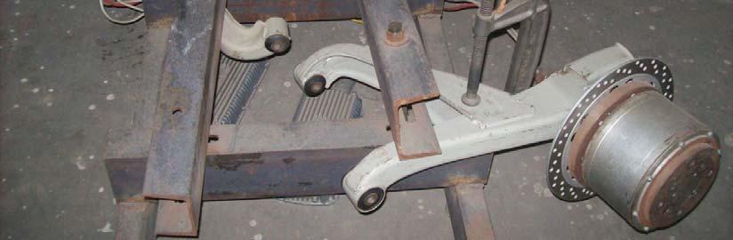
11 Plate 3: Brake Disc, Cover Inner & Retainer with motor shaft assembly on Suspension arm 31

12 Plate 4: PM BLDC Hub Motors Assembly 32

13 Plate 5: Existing car with brake drum assembly 33

14 Plate 6: RH Hub motor with Brake Disc assembly on car 34

15 Plate 7: Hub motor with Brake Caliper assembly on car 35

16 Plate 8: LH Hub motor with Brake Disc assembly on car 36

17 Plate 9: RH and LH Hub motors assembly mounted on car 37

18 Plate 10: RH and LH Wheels mounted on Hub motor 38

19 Plate 11: Set of 4 nos. of 12 Volt Batteries 39

20 Plate 12: Controllers mounted on dickey panel 40

21 Plate 13: Accelerator Pedal 41

22 Plate 14: Battery Charger 42

23 Plate 15: Combined RPM, Speedometer and Trip meter 43

24 Plate 16: Ampere meter, Volt meter and RPM meter 44

25 Plate 17: Fuel Consumption measuring set up 45
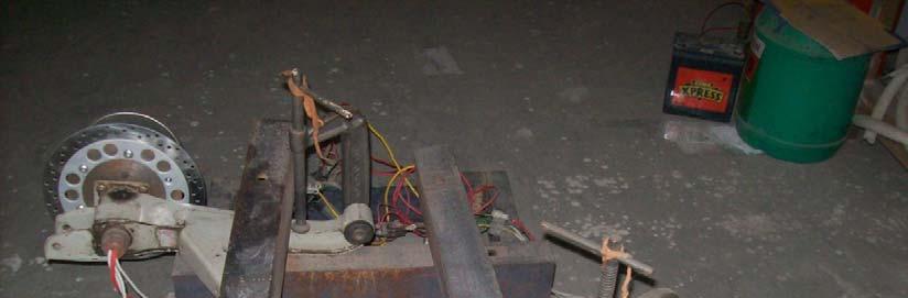
26 Plate 18: Laboratory test set up 46

27 Plate 19: Hybrid Electric Vehicle ready for testing 47
28 Test equipments & experimental set up: The test equipments and experimental set up was fabricated / developed as per the requirement of measurement of performance parameters /test data, for laboratory testing (Plate no.18) and while the vehicle is in motion (Plate no. 15, 16 and 17). Such gadgets were not readily available (e.g. the measurement of Amperes drawn by each motor operating on 48 Volt - DC, but the meter supply voltage being 12 volt DC, similarly all the other meters operating on 12 Volt, DC vehicular battery of), hence were specially made as per order or fabricated. They are all installed for experimentation only. All or any of these equipments may not be part of mandatory requirement on the HEV usage for routine purpose Volt meter: Since the main parameter essential for measuring / recording the performance data required for comparison are state of charge (Voltage across the set of 4 nos. 12 Volt batteries connected in series) of batteries from starting of the test till the batteries are not able to provide sufficient current required to run the motors (to develop torque required to propel the car) any further, a digital Voltmeter is developed (Plate. 16). The digital Voltmeter should be able to indicate state charge for 4 nos. of 12 Volt batteries connected in series, but the LED s display of the volt meter is operational on 12 Volt vehicular battery. Because, the pack of 48 Volt batteries is expected to be charged fully for running of motors and it may be depleted as per the usage. If the volt meter is also operating on the same 48 Volt battery, it may show misleading readings and eventually fail prematurely under fluctuating current drawn. It is important for driver to know/note that how much charge is consumed and how much charge is still remaining, at every stage continuously Ampere meter: Two nos. of Ampere meter (Plate. 16) were developed for measuring the current drawn by each of the motors, to record the level of discharge current drawn at different RPM, load and under varying state of charge of batteries. In production vehicles, total current drawn by both Hub motors can be measured 48
29 by combined single Ampere meter. Not only these meters will indicate performance, it can help in diagnosis of any malfunction, in case of failures or under performance / deterioration in output v/s input. An independent Ampere meter for each motor can help identifying that which motor has developed fault (e.g. if one of the motor is drawing excessive current as compared to other or stopped working) RPM, Speedometer and Trip meter for Electric motors: Two digital display meters (Plate. 15) working on the principle of Proximity sensor based measurement of Motor RPM, separately for both RH & LH motors are developed. These meters are able to measure the RPM and vehicular speed (in unit of measure as Km/hr) of motor always and display the information on distance covered (in Km unit), whether the vehicle is running on IC engine or electric motors. This measurement will verify the recording of analog meter for conventional vehicle running on IC engine, when the vehicle is moving in straight ahead condition. And it will indicate the vehicle speed when the vehicle is Switched ON to move on electric motors. There is one switch provided for switching ON the display of Trip meter. It means, the Trip meter switch should be put ON along with Hub Motors dc voltage supply switch has been put ON. So that the distance covered by the vehicle on electric battery charge from fully charged condition to low voltage condition can be measured. Two separate proximity sensors and combined RPM, Speedometer & Trip meters are developed and installed for knowledge of variations under different running conditions of straight ahead driving, turning and braking as well as variations in respective hub motor performance due to inherent current drawn conditions of RH & LH Hub motors. Also for the routine usage purpose only one such measurement may be sufficient, if the user wants to have the knowledge of distance/mileage covered in electric mode. 49
30 Fuel Consumption Measurement set up: Fuel supply line from fuel tank to fuel feed pump and return fuel line from fuel injection pump to fuel tank are disconnected (both flexible rubber pipes near the engine) at the front end. It was necessary to connect the measuring flask (Plate. 17), so that bleeding of fuel system is achievable and airlock does not occur while running. Also the return line connection is connected to the measuring flask, for accurate measurement of consumption of fuel Part Numbering System: Part numbering system as per (Annexure: 1, 2 and 3) is developed for assisting in identifying the components for reordering, storage, pick and assembly. However, all components are designed such a way that sub-assembly of any components cannot be wrongly done. It means POKA YOKE system is adopted (which is called mistake proofing). The Bill of Materials (BOM) for the conversion kit indicates all the part nos. as per the given part numbering system Methodology for Conversion in to HEV: Methodology adopted for reduction in consumption of fuel in existing diesel cars by fitment of two DC hub motors directly on rear wheels (for front wheel drive vehicles with semi trailing link suspension), for conversion of existing diesel car in to hybrid electric car, is discussed through four heads: i. Process to be followed for assembly of motor on the suspension arm. ii. Installation of suspension arm (with motor assembly) on the vehicle. iii. Installation of test equipments on the test vehicle conventional car converted in to HEV. iv. Testing of vehicle fitted with hub motors by running in IC engine mode and hybrid mode to determine the reduction in consumption of fuel in 50
31 existing diesel car, after converting it in to HEV, with two hub motors fitted directly in the rear wheels. The complete process sheet is given in Annexure: Process for Assembly of Motor on the Suspension arm: The details of step by step methodology is given below i. Step by step process for assembly of motor on the suspension arm begins with concurrent production of parts being kept ready as part of preparation for sub assembly of components and then final assembly of all the components and sub assemblies to make the assembly of motor on the suspension arm. The parts that are required to be manufactured are Axle shaft, Inner grooved sleeve spacer, Inner cover plate and Outer cover plate (with outer bearing hub). ii. Initially the suspension arm assembly from the vehicle is made ready by removing the existing axle shaft. The newly designed and machined shaft is press fitted in the suspension arm, at the same location from where the old axle shaft was removed. iii. As a second step the brake disc is inserted on the shaft and then the Inner plate assembly of Inner Plate and Inner bearing RS1 is press fitted on the axle shaft. iv. The third step is to insert the Sleeve of set of wires inside the inclined hole in the axle shaft. v. Next step is to insert the grooved sleeve, as a spacer on the axle shaft. vi. Press the woodruff key in the key slot provided on the axle shaft. vii. Assemble the stator winding assembly on the axle shaft (by aligning the key slot with the key on the axle shaft). Pull the stator winding from the center of shaft from inside for clearing of slack, if any. viii. Assemble outer bearing sleeve by press fitting on the axle shaft (against stator hub). 51
32 ix. Then insert the assembly rotor housing (sub assembly of rotor housing and permanent magnets), very carefully. x. Fix inner plate assembly to the Rotor housing using six Allen key screws. xi. Fix brake disc plate to the inner plate assembly with six counter sinking screws. xii. Assemble the outer plate assembly (sub assembly of outer plate and outer bearing ) by press fitting. xiii. Fix outer plate assembly to the rotor housing using six Allen key screws. xiv. Use the special washer and fix axle nut. Tighten the axle nut with adequate torque. Tighten lock nut. xv. Fix the bracket for caliper mounting with the lower end of suspension arm. xvi. Last step is to mount caliper assembly on the bracket. (Steps from i to xvi are to be performed in the serial sequence only, as mentioned above) Installation of Suspension arm (with Motor assembly) on the Test vehicle: The assembly of suspension arm with motor RH and assembly of suspension arm with motor LH are to be located in RH and LH side of the rear suspension respectively. i. For installation of the assembly of suspension arm with motor for converting the conventional car in to hybrid electric car, we have to prepare the car by removing certain parts which are not to be used in the hybrid car. Hence, the complete process includes removal of existing parts, discard non usable parts and refit usable along with new parts. In the beginning the steps for removal of parts /assembly parts are mentioned, followed by installation of suspension arm with motor and other parts. Subsequently, steps required to be followed for fitment of the parts removed but, required to be used with the Hybrid car are explained. Some of the steps as part of safety requirement are also list at appropriate locations. ii. Disconnect battery ve terminal connection. 52
33 iii. Put wheel chokes in front and rear of the both front wheels. iv. Put the rear end of vehicle chassis on firm and steady props with both RH & LH wheels clear from the ground. v. Remove wheel rim assembly (with tyre) by loosening four wheel bolts. All four wheel bolts and wheel rim assembly (with tyre) are to be retained for reuse with hybrid conversion. vi. Dismantle shock absorber assembly lower mounting bolt and nuts. Shock absorber and lower mounting bolt nut should be retained for reuse. vii. Dismantle hydraulic brake pipes and hand brake cable connections. Hydraulic pipe and banjo bolts to be reused (but hand brake cable will remain unused for test vehicle only). viii. Dismantle front suspension arm nut bolts for mounting suspension arm with the chassis. The entire suspension arm assembly will be totally disassembled from vehicular chassis. This entire set of assembly of parts including Suspension arm, axle shaft, brake drum assembly, and brake back plate (with brake shoe & wheel cylinder) is to be discarded (Plate. 5). Only the mounting /fixing nut bolts / hardware parts will be reused. ix. Assemble the suspension arm assembly with motor by using / fixing front end mounting nut bolts. x. Assemble the shock absorber lower end mounting nut bolt to the new suspension arm assembly with motor. xi. Connect hydraulic pipe connection with banjo bolt and new banjo washers to the brake calipers. xii. Fix wheel rim with tyre on the outer plate of motor, with the help of 4 wheel bolts. xiii. Carryout the bleeding of hydraulic brake system, as per the standard process, specified by vehicle manufacturer. xiv. Mount the controller in proper position with positive fixing and make connect in to motor connectors. xv. Connect 48 Volt battery bank (4 nos. of 12 Volt each battery connected in series) + ve and ve terminal cables connections to controller, motor, and 53
34 accelerator pedal controller as well as ON OFF switch. Ensure that all the connections are properly insulated and securely fastened, to avoid short circuit problem Installation of Test equipments: (contacts as per the fig. no. 3.21) i. Connect SHUNT on the battery positive cable in series connection. ii. Connect + ve and ve connections of Ampere meter RH as designated on the SHUNT. iii. Repeat these two steps above for connecting Ampere meter LH, also. iv. Connect Voltmeter + ve and ve connections to the + ve and ve terminal connection of 48 V battery bank. v. Connect all the three (two Ampere meters Rh & LH and one Volt meter to + ve and ve terminals of 12 V vehicular battery (or auxiliary 12 Volt battery), because the power source for (LED lights) all the meters is 12 V DC. vi. Mount proximity sensor in appropriate position. vii. Connect sensor and the combined display of RPM/Vehicle speed & Trip meter. viii. Connect power source for this meter also from 12 Volt DC vehicular battery. ix. Finally the set up for measurement of Fuel consumption (Plate. 16): Importantly the main objective of this research project is reduction in consumption of fuel in existing diesel car. The set up is consisting of a Glass bulb of 1 liter capacity having two necks, one used for supplying diesel (connected to the fuel filter inlet, by disconnecting supply line from fuel tank to fuel filter and block it, so that fuel from the tank does not leak) and another neck connected to the return fuel line from fuel injection pump to inverted measuring flask (with its lower most outlet location is above the top level of bulb). A measuring cylinder is connected to the flask reservoir. When the tests are being conducted the bulb must be completely full without any air pocket, so that the measured quantity consumed for a definite distance covered in IC engine power mode OR Electric Motor driving mode as per the test fuel consumption can be measured and recorded for comparison and analysis. 54
35 The return of over flow of diesel from fuel injection pump is dropped back in the measuring flask. Any simple type of flow meter or electronic flow meters for can be also used. 55
Unit HV04K Knowledge of Heavy Vehicle Chassis Units and Components
 Assessment Requirements Unit HV04K Knowledge of Heavy Vehicle Chassis Units and Components Content: Chassis layouts i. types of chassis ii. axle configurations iii. rear steered axles iv. self-steered
Unit AE01K Knowledge of Locating and Correcting Simple Electrical Faults in the Automotive Workplace
 Assessment Requirements Unit AE01K Knowledge of Locating and Correcting Simple Electrical Faults in the Automotive Workplace Content: Basic electrical principles a. Explain the direction of current flow
II YEAR AUTOMOBILE ENGINEERING AT AUTOMOTIVE CHASSIS QUESTION BANK UNIT I - LAYOUT, FRAME, FRONT AXLE AND STEERING SYSTEM
 II YEAR AUTOMOBILE ENGINEERING AT 6402 - AUTOMOTIVE CHASSIS QUESTION BANK UNIT I - LAYOUT, FRAME, FRONT AXLE AND STEERING SYSTEM 1. Write about the requirements of frame and selection of cross section
900, 910, 1100 & 1110
 Long Service Manual 900, 910, 1100 & 1110 Service Manual THIS IS A MANUAL PRODUCED BY JENSALES INC. WITHOUT THE AUTHORIZATION OF LONG OR IT S SUCCESSORS. LONG AND IT S SUCCESSORS ARE NOT RESPONSIBLE FOR
INSTALLATION INSTRUCTIONS
 INSTALLATION INSTRUCTIONS R1 REAR DRUM TO DISC BRAKE CONVERSION KIT A130-3 JEEP CJ SERIES W/AMC-20 REAR AXLES AND 5 x 5-1/2" BOLT CIRCLE Thank you for choosing STAINLESS STEEL BRAKES CORPORATION for your
TWO AND THREE WHEELERS QUESTION BANK UNIT I: POWER PLANT
 TWO AND THREE WHEELERS QUESTION BANK UNIT I: POWER PLANT What do you mean by scavenging? Why it is necessary? What are the types of scavenging pumps? What is scavenging pump? Draw symmetrical and unsymmetrical
INSTALLATION INSTRUCTIONS
 INSTALLATION INSTRUCTIONS REAR DRUM TO DISC BRAKE CONVERSION KIT A118 pre-1985 Ford F150 (except 1983-1984 w/super H/D axle) Thank you for choosing STAINLESS STEEL BRAKES CORPORATION for your braking needs.
REAR AXLE GROUP CONTENTS GENERAL DESCRIPTION REAR AXLE DIAGNOSIS REAR AXLE HUB ASSEMBLY KNUCKLE...
 27-1 GROUP 27 CONTENTS GENERAL DESCRIPTION......... 27-2 DIAGNOSIS......... 27-2 INTRODUCTION TO DIAGNOSIS........................ 27-2 DIAGNOSTIC TROUBLESHOOTING STRATEGY...... 27-2 SYMPTOM CHART...................
Installation Instructions
 Installation Instructions Rear Disc Brake Conversion Kit Item # RC2001, RC2001X Applications: Mopar 8-3/4 & 9-3/4 Rear Axles Thank you for choosing Leed Brakes for your automotive product needs. Before
OPERATOR'S MANUAL COMPONENT OF CRUSHING AND SCREENING PLANT: DIESEL AND ELECTRIC DRIVEN, WHEEL MOUNTED, 75 TON PER HOUR
 OPERATOR'S MANUAL FOR CRUSHER, ROLL: DIESEL AND ELECTRIC DRIVEN, WHEEL MOUNTED, PNEUMATIC TIRES, 75 TON PER HOUR EAGLE CRUSHER MODEL 5230B AND 5230C (NSN 3820-00-788-5999) EAGLE CRUSHER MODEL 5230D (NSN
Design of Alternative Automatic Transmission for Electric Mopeds Ameya Bhusari 1, Saurabh Rege 2
 Design of Alternative Automatic Transmission for Electric Mopeds Ameya Bhusari 1, Saurabh Rege 2 1 Department of Mechanical, Maharashtra Institute of Technology, PUNE-38 2 Department of Mechanical, Modern
This chapter covers the location and servicing of the front brake components for the KYMCO MXU 700i and MXU 500i models.
 KYMCO MXU 500i/700i Repair Manual Brake System 9.Brake System This chapter covers the location and servicing of the front brake components for the KYMCO MXU 700i and MXU 500i models. 1.Brake Discs... 9-3
OCTOPUS SERVICE PROCEDURE - SP007 REV NEW 15-FEB-2008
 OCTOPUS SERVICE PROCEDURE - SP007 REV NEW 15-FEB-2008 APPLICABLE MODELS a. Both styles of Octopus Hydraulic 38mm Bore Linear Drive. (LAM = Linear Actuator Mounted & LAR = Linear Actuator Remote) REQUIRED
Inspection and Verification, Ranger
 file://c:\tso\tsocache\vdtom_5368\svk~us~en~file=svk53a03.htm~gen~ref.htm Page 1 of 1 Section 05-03A: Wheel Hubs and Bearings, Front Wheels, 4- Wheel Drive DIAGNOSIS AND TESTING 1997 Ranger 4x4 with Dana
APPLIED MECHANICS 40/50
 APPLIED MECHANICS 40/50 Description (Combined Course- 2 periods) Applied Mechanics 40 introduces students to automobile servicing and the maintenance/repair field. Work is performed on operational vehicles.
SYLLABUS. osmania university UNIT - I UNIT - II UNIT - III UNIT - IV CHAPTER - 1 : PRINCIPLES OF ELECTRO-MECHANICAL ENERGY CONVERSION CHAPTER - 2 :
 i UNIT - I SYLLABUS osmania university UNIT - II CHAPTER - 1 : PRINCIPLES OF ELECTRO-MECHANICAL ENERGY CONVERSION Energy in Magnetic System, Field Energy and Mechanical Force, Direction of Mechanical Force
TECHNICAL MANUAL OPERATOR S, ORGANIZATIONAL, DIRECT SUPPORT AND GENERAL SUPPORT MAINTENANCE MANUAL (INCLUDING REPAIR PARTS AND SPECIAL TOOLS LIST)
") TECHNICAL MANUAL OPERATOR S, ORGANIZATIONAL, DIRECT SUPPORT AND GENERAL SUPPORT MAINTENANCE MANUAL (INCLUDING REPAIR PARTS AND SPECIAL TOOLS LIST) SEMITRAILER, VAN: ELECTRONIC 10-TON, 4 WHEEL XM574 (2330-00-086-7406)
TECHNICAL MANUAL OPERATOR S, ORGANIZATIONAL, DIRECT SUPPORT AND GENERAL SUPPORT MAINTENANCE MANUAL (INCLUDING REPAIR PARTS AND SPECIAL TOOLS LIST) SEMITRAILER, VAN: ELECTRONIC 10-TON, 4 WHEEL XM574 (2330-00-086-7406)
INSTALLATION INSTRUCTIONS
 INSTALLATION INSTRUCTIONS REAR DISC CONVERSION KIT A136-1 1976-86 AMC 20 AXLES WITH WARN FULL FLOATING AXLE CONVERSION Thank you for choosing STAINLESS STEEL BRAKES CORPORATION for your braking needs.
READ AND UNDERSTAND ALL INSTRUCTIONS AND WARNINGS PRIOR TO INSTALLATION OF SYSTEM AND OPERATION OF VEHICLE.
 #021700, 021701 7 Suspension System 2000-2004 Chevy/GMC 1500 2wd Extended Cab w/ Front Coil Springs READ AND UNDERSTAND ALL INSTRUCTIONS AND WARNINGS PRIOR TO INSTALLATION OF SYSTEM AND OPERATION OF VEHICLE.
1 Part Number: M-2300-Y Part Description: S550 Mustang-Shelby Brake Upgrade Kit Installation Instructions
 Please visit www.performanceparts.ford.com for the most current instruction and warranty information. PLEASE READ ALL OF THE FOLLOWING INSTRUCTIONS CAREFULLY PRIOR TO INSTALLATION. AT ANY TIME YOU DO NOT
INSTALLATION INSTRUCTIONS
 INSTALLATION INSTRUCTIONS FORCE 10 SPORT R1 REAR DISC CONVERSION KIT A126-50 2005-10 Chevrolet Silverado and GMC Sierra Thank you for choosing STAINLESS STEEL BRAKES CORPORATION for your braking needs.
VECTRIX VX-2 SERVICE MANUAL. Version 1.0/May 2011 VECTRIX, LLC
 www.vectrix.com CONTENTS SECTION A: Tools 1 Tools Needed SECTION B: Mechanical Parts 1 Front Fairing 2 Front Console Cover 3 Speedometer Cover 4 Front Vertical Panel Cover-Lower 5 Front Vertical Panel
INSTALLATION INSTRUCTIONS PERFORMANCE AT THE WHEELS KIT W125
 INSTALLATION INSTRUCTIONS PERFORMANCE AT THE WHEELS KIT W125 1968-81 CAMARO & FIREBIRD 10 & 12 BOLT W/"C" CLIPS Thank you for choosing STAINLESS STEEL BRAKES CORPORATION for your braking needs. Pleases
INSTALLATION INSTRUCTIONS
 INSTALLATION INSTRUCTIONS REAR DISC BRAKE CONVERSION KIT A157 1991-2004 Dodge Dakota 2WD 1991-2002 Dodge Dakota 4WD 1998-2002 Dodge Durango Thank you for choosing STAINLESS STEEL BRAKES CORPORATION for
Installation Instructions
 Preparing your vehicle to install your brake system upgrade 1. Rack the vehicle. 2. If you don t have a rack, then you must take extra safety precautions. 3. Choose a firmly packed and level ground to
BASIC BRAKE SYSTEM GROUP 35A 35A-1 CONTENTS GENERAL DESCRIPTION... 35A-3 BASIC BRAKE SYSTEM DIAGNOSIS 35A-6
 35A-1 GROUP 35A BASIC BRAKE SYSTEM CONTENTS GENERAL DESCRIPTION......... 35A-3 DIAGNOSIS 35A-6 INTRODUCTION..................... 35A-6 DIAGNOSTIC TROUBLESHOOTING STRATEGY......................... 35A-6
INSTALLATION INSTRUCTIONS
 INSTALLATION INSTRUCTIONS REAR DISC BRAKE CONVERSION KIT A158 1994-97 Dodge Ram 1500 (2WD & 4WD) and REAR DISC BRAKE CONVERSION KIT A158-1 1998-01 Dodge Ram 1500 (2WD & 4WD) Thank you for choosing STAINLESS
Installation Instructions
 Installation Instructions Rear Disc Brake Conversion Kit Item # RC4001, RC4001X Applications: Mopar 7.25, 8.25, 9.25 Axles Thank you for choosing Leed Brakes for your automotive product needs. Before you
Contents. Preface... xiii Introduction... xv. Chapter 1: The Systems Approach to Control and Instrumentation... 1
 Contents Preface... xiii Introduction... xv Chapter 1: The Systems Approach to Control and Instrumentation... 1 Chapter Overview...1 Concept of a System...2 Block Diagram Representation of a System...3
TECHNICAL MANUAL UNIT, INTERMEDIATE DIRECT SUPPORT AND INTERMEDIATE GENERAL SUPPORT MAINTENANCE MANUAL
 TM 5-3820-256-24-4 TECHNICAL MANUAL UNIT, INTERMEDIATE DIRECT SUPPORT AND INTERMEDIATE GENERAL SUPPORT MAINTENANCE MANUAL DRILLING SYSTEM, WELL, ROTARY, TRUCK MOUNTED, AIR TRANSPORTABLE, 600 FEET CAPACITY
ASSEMBLY INSTRUCTIONS FOR PART NUMBER GROUP
 ASSEMBLY INSTRUCTIONS FOR DYNAPRO 6 BIG BRAKE FRONT HAT KIT, 1.19 DIAMETER VENTED ROTOR 1990-005 ACURA/CIVIC ( LUG) 000-003 CIVIC SI ( LUG) 007 - PRESENT HONDA FIT FOR FACTORY 6 mm DISC SPINDLE PART NUMBER
INSTALLATION INSTRUCTIONS R1 REAR CONVERSION KIT
 INSTALLATION INSTRUCTIONS R1 REAR CONVERSION KIT INSTRUCTION FOR ASSEMBLY OF JEEP CJ SERIES W/AMC 20 REAR AXLES, 5 x 5-1/2" BOLT CIRCLE WITH A130-4 FULL FLOATING AXLE OR A130-5 (1 PIECE AXLE) Thank you
ASSEMBLY INSTRUCTIONS FOR DYNALITE DRAG RACE FRONT HUB KIT WITH DIAMETER SOLID ROTOR PINTO / MUSTANG II
 ASSEMBLY INSTRUCTIONS FOR DYNALITE DRAG RACE FRONT HUB KIT WITH 0.75 DIAMETER SOLID ROTOR 97-978 PINTO / MUSTANG II (FIVE LUG CONFIGURATION ONLY)* PART NUMBER GROUP 0-03-B DISC BRAKES SHOULD ONLY BE INSTALLED
2012 MKT Workshop Manual. REMOVAL AND INSTALLATION Procedure revision date: 06/13/2011
 SECTION 205-05: Rear Drive Halfshafts REMOVAL AND INSTALLATION Procedure revision date: 06/13/2011 Halfshaft Special Tool(s) Axle Seal Protector 205-816 Front Hub Remover 205-D070 (D93P-1175-B) or equivalent
GROUP SIX LIGHTS. Contents of this group:- Tools required for assembly of this group: - 8mm Spanner K AA TAIL LIGHTS K AB HEAD LIGHTS
 GROUP SIX st Edition LIGHTS Contents of this group:- 6: K360AA TAIL LIGHTS 6: K360AB HEAD LIGHTS 6:3 K3603AB WIRING 6: K3605AB WIRING AND SWITCHES 6:5 K360AA INDICATOR PILOT LIGHTS Tools required for assembly
INSTALLATION INSTRUCTIONS
 INSTALLATION INSTRUCTIONS INSTALLATION INSTRUCTIONS FOR A136 REAR DRUM TO DISC BRAKE CONVERSION KIT for 1970-75 Jeep, CJ SERIES with Dana 44 flanged axle Thank you for choosing STAINLESS STEEL BRAKES CORPORATION
INSTALLATION INSTRUCTIONS
 INSTALLATION INSTRUCTIONS POWER FRONT DISC CONVERSION KIT A126-7 1963-66 CHEVY C10 PICKUP NON-POWER FRONT DISC CONVERSION KIT A126-8 1963-72 CHEVY C10 PICKUP Thank you for choosing STAINLESS STEEL BRAKES
DISC BRAKE/DUAL MASTER CYLINDER CONVERSION. Tools, Equipment and Supplies Needed:
 Please take the time to read the enclosed instructions carefully. If you have any questions, call our Product Assistance personnel for clarification. It is important to note that these instructions contain
Title: FRONT BRAKE VIBRATION Models: Tundra. Front Brake Caliper & Rotor Replacement (2WD, Both Sides)
") Technical Service BULLETIN September 16, 2002 Title: FRONT BRAKE VIBRATION Models: 00-03 Tundra BR004-02 BRAKES TSB REVISION NOTICE: S March 5, 2004: A torque speification on page 10, step 24, was changed.
Technical Service BULLETIN September 16, 2002 Title: FRONT BRAKE VIBRATION Models: 00-03 Tundra BR004-02 BRAKES TSB REVISION NOTICE: S March 5, 2004: A torque speification on page 10, step 24, was changed.
TECHNICAL MANUAL AVIATION UNIT AND AVIATION INTERMEDIATE MAINTENANCE MANUAL ENGINE, GAS TURBINE MODEL T55-L-714 NSN
 TECHNICAL MANUAL AVIATION UNIT AND AVIATION INTERMEDIATE MAINTENANCE MANUAL ENGINE, GAS TURBINE MODEL T55-L-714 NSN 2840-01-353-7635 DISTRIBUTION STATEMENT A: Approved for public release; distribution
INSTALLATION INSTRUCTIONS
 INSTALLATION INSTRUCTIONS REAR DISC BRAKE CONVERSION KIT A126-1 1973-87 CHEVROLET 1/2 TON 2WD Thank you for choosing STAINLESS STEEL BRAKES CORPORATION for your braking needs. Pleases take the time to
CHAPTER 4 HARDWARE DEVELOPMENT OF DUAL ROTOR RADIAL FLUX PERMANENT MAGNET GENERATOR FOR STAND-ALONE WIND ENERGY SYSTEMS
 66 CHAPTER 4 HARDWARE DEVELOPMENT OF DUAL ROTOR RADIAL FLUX PERMANENT MAGNET GENERATOR FOR STAND-ALONE WIND ENERGY SYSTEMS 4.1 INTRODUCTION In this chapter, the prototype hardware development of proposed
Department of Mechanical Engineering UBMC701 AUTOMOBILE ENGINEERING QUESTION BANK VEHICLE STRUCTURE AND ENGINES. Part A (Two Marks Questions)
") Department of Mechanical Engineering UBMC701 AUTOMOBILE ENGINEERING QUESTION BANK UNIT- I VEHICLE STRUCTURE AND ENGINES 1. Define Automobile. Give the typical specifications of an automobile 2. Name the
Department of Mechanical Engineering UBMC701 AUTOMOBILE ENGINEERING QUESTION BANK UNIT- I VEHICLE STRUCTURE AND ENGINES 1. Define Automobile. Give the typical specifications of an automobile 2. Name the
BIG BRAKE KIT FOR TJ, ZJ, XJ D44 & D30
 BIG BRAKE KIT FOR TJ, ZJ, XJ D44 & D30 16 KIT PART NUMBER 41002010AA 17 KIT PART NUMBER 41002015AA Installation Guide (Updated 12/01/09) Page 1 of 11 PLEASE READ BEFORE YOU START IN ORDER TO INSTALL THIS
TECHNICAL MANUAL UNIT, INTERMEDIATE DIRECT SUPPORT AND INTERMEDIATE GENERAL SUPPORT MAINTENANCE MANUAL
 TM 5-3820-256-24-1 TECHNICAL MANUAL UNIT, INTERMEDIATE DIRECT SUPPORT AND INTERMEDIATE GENERAL SUPPORT MAINTENANCE MANUAL DRILLING SYSTEM, WELL, ROTARY, TRUCK MOUNTED, AIR TRANSPORTABLE, 600 FEET CAPACITY
Unit MC07K Knowledge of Diagnosis and Rectification of Motorcycle Engine Faults
 Assessment Requirements Unit MC07K Knowledge of Diagnosis and Rectification of Motorcycle Engine Faults Content: Single cylinder and multi-cylinder fuel injection systems a. The operation and construction
OPERATOR'S MANUAL FOR
 OPERATOR'S MANUAL FOR CRUSHER, JAW: DIESEL AND ELECTRIC DRIVEN, WHEEL MOUNTED, PNEUMATIC TIRES, 75 TON PER HOUR EAGLE CRUSHER MODEL 5157 AND 5157A (NSN 3820-00-783-7311) EAGLE CRUSHER MODEL 5157B (NSN
EXPERIMENT CALIBRATION OF 1PHASE ENERGY METER
 EXPERIMENT CALIBRATION OF PHASE ENERGY METER THEORY:- Energy Meters are integrating instruments used to measure the quantity of electrical energy supplied to a circuit in a given time. Single phase energy
ALLDATA Online Jaguar Vanden Plas L6-3980cc 4.0L DOHC - Service and Rep...
 Page 1 of 7 RENEW Jack up the front of the vehicle. Fit camber tie-down bars (Service Tool JD 133) to the road spring pans. NOTE: If, for any reason, the front crossmember is being stripped down, Service
Telephone (925) Fax (925) Lawrence Drive, Livermore, CA 94551
 Fax (925) Lawrence Drive, Livermore, CA 94551") Telephone (95) 454-9500 Fax (95) 454-950 5 Lawrence Drive, Livermore, CA 9455 PARTS MANUAL INDEX STEERABLE DRIVE AXLE ASSEMBLY STEERABLE DRIVE END ASSEMBLY BRAKE CALIPER ASSEMBLY TO USE THIS BOOK:. Refer
Telephone (95) 454-9500 Fax (95) 454-950 5 Lawrence Drive, Livermore, CA 9455 PARTS MANUAL INDEX STEERABLE DRIVE AXLE ASSEMBLY STEERABLE DRIVE END ASSEMBLY BRAKE CALIPER ASSEMBLY TO USE THIS BOOK:. Refer
L_All_Vocational_Ed_Auto. Sector: Automobile. S.No Specialization Page No. 1 Automobile 2-15
 L_All_Vocational_Ed_Auto Sector: Automobile S.No Specialization Page No. 1 Automobile 2-15 1 NATIONAL VOCATIONAL EDUCATION QUALIFICATION FRAMEWORK SECTOR: AUTOMOBILE SPECIALIZATION: AUTOMOBILE S.No. Certificate
Maintenance and Parts Manual ADZ Series Suspension
 Maintenance and Parts Manual ADZ Series Suspension XL-PS10452MM-en-US Rev C Contents Contents Page Introduction... 3 Warranty... 3 Notes, Cautions, and Warnings... 3 Section 1 General Safety Instructions...
INSTALLATION INSTRUCTIONS
 INSTALLATION INSTRUCTIONS REAR DISC BRAKE CONVERSION KIT A125-2 1955-70 FULL SIZE CHEVROLET Thank you for choosing STAINLESS STEEL BRAKES CORPORATION for your braking needs. Pleases take the time to read
TECHNICAL MANUAL AVIATION UNIT AND AVIATION INTERMEDIATE MAINTENANCE MANUAL ENGINE, GAS TURBINE MODEL T55-L-714 NSN
 TM 1-2840-252-23--2 TECHNICAL MANUAL AVIATION UNIT AND AVIATION INTERMEDIATE MAINTENANCE MANUAL ENGINE, GAS TURBINE MODEL T55-L-714 NSN 2840-01-353-7635 DISTRIBUTION STATEMENT A: Approved for public release,
B.E-EEE(Marine) Batch 7. Subject Code EE1704 Subject Name Special Electrical Machines
 Batch 7. Subject Code EE1704 Subject Name Special Electrical Machines") Course B.E-EEE(Marine) Batch 7 Semester VII Subject Code EE1704 Subject Name Special Electrical Machines Part-A Unit-1 1 List the applications of synchronous reluctance motors. 2 Draw the voltage and torque
Course B.E-EEE(Marine) Batch 7 Semester VII Subject Code EE1704 Subject Name Special Electrical Machines Part-A Unit-1 1 List the applications of synchronous reluctance motors. 2 Draw the voltage and torque
INSTALLATION INSTRUCTIONS
 INSTALLATION INSTRUCTIONS REAR CONVERSION KIT A111-2 (FORD 8" & 9" SMALL BEARING) & REAR CONVERSION KIT A111-3 (FORD 9 TORINO) Thank you for choosing STAINLESS STEEL BRAKES CORPORATION for your braking
SUSPENSION 2-1 SUSPENSION CONTENTS
 TJ SUSPENSION 2-1 SUSPENSION CONTENTS page ALIGNMENT... 1 FRONT SUSPENSION... 6 page REAR SUSPENSION... 13 ALIGNMENT INDEX page DESCRIPTION AND OPERATION WHEEL ALIGNMENT... 1 DIAGNOSIS AND TESTING SUSPENSION
POMPE AUTOADESCANTI SELF-PRIMING ELECTRO PUMP ACM DISASSEMBLY AND ASSEMBLY INSTRUCTIONS FOR MULTISTAGE SELF-PRIMING PUMPS
 POMPE AUTOADESCANTI SELF-PRIMING ELECTRO PUMP ACM DISASSEMBLY AND ASSEMBLY INSTRUCTIONS FOR MULTISTAGE SELF-PRIMING PUMPS Ed. 02/2011 5 WARNING These instructions are for the maintenance personnel for
NECO Pumping Systems
 INSTALLATION OPERATION & MAINTENANCE INSTRUCTIONS For Your NECO Pumping Systems PACKAGED CIRCULATING SYSTEM THIS COMPLETELY ASSEMBLED, TESTED, PACKAGED CIRCULATING SYSTEM IS OF THE HIGHEST QUALITY AND
GROUP 35A 35A-1 CONTENTS GENERAL DESCRIPTION... 35A-3 BASIC BRAKE SYSTEM DIAGNOSIS 35A-6 HYDRAULIC BRAKE BOOSTER (HBB) DIAGNOSIS...
 DIAGNOSIS...") 35A-1 GROUP 35A CONTENTS GENERAL DESCRIPTION......... 35A-3 DIAGNOSIS 35A-6 INTRODUCTION..................... 35A-6 DIAGNOSTIC TROUBLESHOOTING STRATEGY......................... 35A-6 SYMPTOM CHART...................
35A-1 GROUP 35A CONTENTS GENERAL DESCRIPTION......... 35A-3 DIAGNOSIS 35A-6 INTRODUCTION..................... 35A-6 DIAGNOSTIC TROUBLESHOOTING STRATEGY......................... 35A-6 SYMPTOM CHART...................
TECHNICAL MANUAL DIRECT SUPPORT AND GENERAL SUPPORT MAINTENANCE MANUAL CRANE, WHEEL MOUNTED: 20 TON AT 10 FOOT RADIUS;
 DEPARTMENT OF THE ARMY TECHNICAL MANUAL TM 5-3810-232-34 TECHNICAL MANUAL DIRECT SUPPORT AND GENERAL SUPPORT MAINTENANCE MANUAL CRANE, WHEEL MOUNTED: 20 TON AT 10 FOOT RADIUS; 2 ENGINES, DIESEL ENGINE
Fuzzy based STATCOM Controller for Grid connected wind Farms with Fixed Speed Induction Generators
 Fuzzy based STATCOM Controller for Grid connected wind Farms with Fixed Speed Induction Generators Abstract: G. Thrisandhya M.Tech Student, (Electrical Power systems), Electrical and Electronics Department,
AEV30308AA Last Updated: 05/31/18. 4 DUALSPORT sc SUSPENSION system for RAM 1500 air ride standard and rebel INSTALLATION GUIDE
 AEV30308AA Last Updated: 05/31/18 4 DUALSPORT sc SUSPENSION system for RAM 1500 air ride standard and rebel INSTALLATION GUIDE PLEASE READ BEFORE YOU START TO GUARANTEE A QUALITY INSTALLATION, WE RECOMMEND
INSTALLATION INSTRUCTION 88581
 INSTALLATION INSTRUCTION 88581 FOR RANCHO SUSPENSION SYSTEM RS6581B: DODGE RAM READ ALL INSTRUCTIONS THOROUGHLY FROM START TO FINISH BEFORE BEGINNING INSTALLATION Rev C IMPORTANT NOTES! WARNING: This suspension
55-64 Full Size Chevy
 55-64 Full Size Chevy Installation Instructions Power Disc Conversion 9 slimline booster pictured Your new disc brake conversion kit can be bolted up with standard hand tools. The only tools you may not
55-64 Full Size Chevy Installation Instructions Standard Disc Conversion
 55-64 Full Size Chevy Installation Instructions Standard Disc Conversion DBMC09, PV71 & PVB71 Pictured (Booster, master cylinder & valve setups may vary by upgrades selected) Your new disc brake conversion
How it s done Fitting instructions for replacing brakes
 How it s done Fitting instructions for replacing brakes Fitting instructions for replacing brakes We invest a lot in developing our products. We complete up to 300,000 test kilometres and 1,000 hours of
SUSPENSION 2-1 SUSPENSION CONTENTS
 ZJ SUSPENSION 2-1 SUSPENSION CONTENTS page ALIGNMENT... 1 FRONT SUSPENSION... 6 page REAR SUSPENSION... 14 ALIGNMENT INDEX page GENERAL INFORMATION WHEEL ALIGNMENT... 1 DIAGNOSIS AND TESTING SUSPENSION
Rover SD1 Efi System Fuel Supply Components - Explanation and Testing of the Fuel Pump, Filter and Fuel Pressure Regulator
 Rover SD1 Efi System Fuel Supply Components - Explanation and Testing of the Fuel Pump, Filter and Fuel Pressure Regulator Introduction Some of the notes here are repetitious in order to review the components
HOUSTON OILFIELD EQUIPMENT 9669 PORT ERROLL RD. HOUSTON, TX PHONE: (713) FAX: (713)
 FAX: (713)") HOUSTON OILFIELD EQUIPMENT 9669 PORT ERROLL RD. HOUSTON, TX 77095 PHONE: (713) 466-3797 FAX: (713) 466-3189 INSTALLATION AND MAINTENANCE INSTRUCTION MANUAL 10M CWP H-JWAl HPC ADJUSTABLE CHOKE AND POSITIVE
HOUSTON OILFIELD EQUIPMENT 9669 PORT ERROLL RD. HOUSTON, TX 77095 PHONE: (713) 466-3797 FAX: (713) 466-3189 INSTALLATION AND MAINTENANCE INSTRUCTION MANUAL 10M CWP H-JWAl HPC ADJUSTABLE CHOKE AND POSITIVE
POWER METER. my2010 (c)
") POWER METER ELECTRIC POWER Electric power is the rate at which electric energy is transferred by an electric circuit. The SI unit of power is the watt. When electric current flows in a circuit, it can
POWER METER ELECTRIC POWER Electric power is the rate at which electric energy is transferred by an electric circuit. The SI unit of power is the watt. When electric current flows in a circuit, it can
Technical Service BULLETIN
 Technical Service BULLETIN September 16, 2002 Title: Models: 01 02 Sequoia BR005-02 BRAKES TSB REVISION NOTICE: March 5, 2004: A torque specification on page 9, step 24, was changed. September 8, 2003:
1994 Mazda MX-5 Miata. BRAKE SYSTEM 1994 BRAKES Mazda - Disc & Drum BRAKES Mazda - Disc & Drum
 BRAKE PEDAL FREE PLAY 1994 Mazda MX-5 Miata DESCRIPTION & OPERATION BRAKE SYSTEM 1994 BRAKES Mazda - Disc & Drum NOTE: For information on anti-lock brake systems, see ANTI-LOCK BRAKE SYSTEM article in
To study the constructional features of ammeter, voltmeter, wattmeter and energymeter.
 Experiment o. 1 AME OF THE EXPERIMET To study the constructional features of ammeter, voltmeter, wattmeter and energymeter. OBJECTIVE 1. To be conversant with the constructional detail and working of common
IMILV01 Carry out routine light vehicle maintenance
 IMILV01 Carry out routine light vehicle maintenance Overview This NOS is about conducting routine maintenance, adjustment and replacement activities as part of the periodic servicing of light vehicles.
INSTALLATION INSTRUCTIONS
 INSTALLATION INSTRUCTIONS PERFORMANCE AT THE WHEELS KIT W155-5 CHRYSLER 8 3 /4" & 9 3 /4" REAR AXLES Thank you for choosing STAINLESS STEEL BRAKES CORPORATION for your braking needs. Please take the time
Service Bulletin No. 3033
 MODEL TYPE SECTION/GROUP DATE G Series Coaches Product Improvement 2--Rear Axle Mar. 31, 2010 SUBJECT CONDITIONS BEARING BOX Parts may be purchased from MCI Service Parts, Louisville, Kentucky or from
SECTION D Fuel Charging and Controls Turbocharger
 303-04D-i Fuel Charging and Controls Turbocharger 303-04D-i SECTION 303-04D Fuel Charging and Controls Turbocharger CONTENTS PAGE Turbocharger Body On... 303-04D-2 303-04D-2 Fuel Charging and Controls
CHAPTER 1 INTRODUCTION
 CHAPTER 1 INTRODUCTION 1.1 CONSERVATION OF ENERGY Conservation of electrical energy is a vital area, which is being regarded as one of the global objectives. Along with economic scheduling in generation
INSTALLATION INSTRUCTIONS
 INSTALLATION INSTRUCTIONS REAR DISC BRAKE CONVERSION KITS A112, A112-1 & A112-93 1979-93 FORD MUSTANG with 7.5" & 8.8" AXLES Thank you for choosing STAINLESS STEEL BRAKES CORPORATION for your braking needs.
SMF / DSF / DTF SMF / DSF / DTF 200
 2006 SMF / DSF / DTF 200 1 The drawings in this parts book have been scaled so that parts can be easily recognized. 1 CYLINDER ASSY 2 CYLINDER ASSY Ref # Part # Description 1 410 0001A CYLINDER HEAD COVER
MicrofichesExcel. Tavola Posizione Codice Quant Ing
 Tavola Posizione Codice Quant Ing 1 1 T1P52MI-A-011200 1 LH Crankcase 1 2 T1P52MI-A-011300 1 RH Crankcase 1 3 T11119 1 Crankcase gasket 1 4 TOR00037 4 Screw M5 6 1 5 T1P52MI-011400 2 Bush 1 6 T11118 2
INSTALLATION INSTRUCTIONS
 INSTALLATION INSTRUCTIONS REAR DISC BRAKE CONVERSION KIT A125-3 1965-72 GM A-BODY 10 & 12 BOLT AXLES Thank you for choosing STAINLESS STEEL BRAKES CORPORATION for your braking needs. Pleases take the time
REMOVAL & INSTALLATION
 REMOVAL & INSTALLATION FRONT DISC BRAKE PADS 1. Raise and support front of vehicle. Remove wheels. Remove caliper bolt and brakeline bracket bolts. Pivot caliper aside. Remove pads and pad shim. Remove
ALL NISSAN, BRAKE NOISE/JUDDER/PEDAL FEEL DIAGNOSIS AND REPAIR
 Classification: Reference: Date: BR00-004a NTB00-033a June 11, 2003 ALL NISSAN, BRAKE NOISE/JUDDER/PEDAL FEEL DIAGNOSIS AND REPAIR IMPORTANT: THIS BULLETIN HAS BEEN REVISED A note (*) was revised on page
1 1/2-TON, 2-WHEEL, M332 PAGE B1 (NSN ) REPAIR PARTS AND SPECIAL TOOLS LIST PAGE F-1
 REPAIR PARTS AND SPECIAL TOOLS LIST PAGE F-1") TECHNICAL MANUAL OPERATOR'S, ORGANIZATIONAL, DIRECT SUPPORT, AND GENERAL SUPPORT MAINTENANCE (INCLUDING REPAIR PARTS AND SPECIAL TOOLS LIST) OPERATING INSTRUCTIONS PAGE 2-1 OPERATOR PMCS PAGE 2-4 OPERATOR
TECHNICAL MANUAL OPERATOR'S, ORGANIZATIONAL, DIRECT SUPPORT, AND GENERAL SUPPORT MAINTENANCE (INCLUDING REPAIR PARTS AND SPECIAL TOOLS LIST) OPERATING INSTRUCTIONS PAGE 2-1 OPERATOR PMCS PAGE 2-4 OPERATOR
ANTI-LOCK BRAKE SYSTEM - REAR WHEEL
 ANTI-LOCK BRAKE SYSTEM - REAR WHEEL 1994 Nissan Pickup 1994 BRAKES Nissan - Rear Anti-Lock Pathfinder, Pickup DESCRIPTION In 2WD mode, Rear Anti-Lock Brake System (RABS) helps the driver to maintain steering
SUSPENSION 2-1 SUSPENSION CONTENTS
 TJ SUSPENSION 2-1 SUSPENSION CONTENTS page ALIGNMENT... 1 FRONT SUSPENSION... 5 page REAR SUSPENSION... 12 ALIGNMENT INDEX page GENERAL INFORMATION WHEEL ALIGNMENT... 1 DIAGNOSIS AND TESTING SUSPENSION
EXPERIMENTAL VERIFICATION OF INDUCED VOLTAGE SELF- EXCITATION OF A SWITCHED RELUCTANCE GENERATOR
 EXPERIMENTAL VERIFICATION OF INDUCED VOLTAGE SELF- EXCITATION OF A SWITCHED RELUCTANCE GENERATOR Velimir Nedic Thomas A. Lipo Wisconsin Power Electronic Research Center University of Wisconsin Madison
Accessory Fitting Instructions
 Accessory Fitting Instructions Kit Number Models Affected A9689 Thruxton 00 A96808 Thruxton 00 R Low Handlebar Kit Front Fairing Kit Kit Number Models Affected A97080 Thruxton 00 A97084 Thruxton 00 R Note:
CHAPTER 5 ANALYSIS OF COGGING TORQUE
 95 CHAPTER 5 ANALYSIS OF COGGING TORQUE 5.1 INTRODUCTION In modern era of technology, permanent magnet AC and DC motors are widely used in many industrial applications. For such motors, it has been a challenge
M-2300-T 6-Piston Mustang Brake Kit INSTALLATION INSTRUCTIONS
 Please visit www.fordracingparts.com for the most current instruction information!!! PLEASE READ ALL OF THE FOLLOWING INSTRUCTIONS CAREFULLY PRIOR TO INSTALLATION. AT ANY TIME YOU DO NOT UNDERSTAND THE
SIMULINK Based Model for Determination of Different Design Parameters of a Three Phase Delta Connected Squirrel Cage Induction Motor
 IOSR Journal of Electrical and Electronics Engineering (IOSR-JEEE) e-issn: 2278-1676,p-ISSN: 2320-3331, Volume 7, Issue 4 (Sep. - Oct. 2013), PP 25-32 SIMULINK Based Model for Determination of Different
Emotron FDU and VFX 2.0
 Emotron FDU and VFX 2.0 AC drives with protection class IP20 and IP21 7.5-132 kw Addendum to instruction manual English Software version 4.3X Addendum valid for Emotron FDU and Emotron VFX AC drives This
1 M-3000-H4 F150 4X4 Lowering Kit
 READ INSTRUCTIONS COMPLETELY THROUGH BEFORE STARTING. IT IS RECOMMENDED THAT INSTALLATION BE DONE BY A QUALIFIED MECHANIC. REPLACE ALL STOCK PARTS THAT ARE DAMAGED OR WORN. ALWAYS WEAR EYE PROTECTION.
ASSEMBLY INSTRUCTIONS
 ASSEMBLY INSTRUCTIONS FOR DYNALITE PRO SERIES FRONT HUB KIT WITH.75 DIAMETER VENTED ROTOR 970-973 FORD MUSTANG (DRUM / DISC SPINDLE) PART NUMBER GROUP 0-905 WARNING INSTALLATION OF THIS KIT SHOULD ONLY
If it exceeds the maximum specification, replace the propeller shaft.
 If it exceeds the maximum specification, replace the propeller shaft. Maximum runout o 0.4 mm {0.016 in} 2. Inspect the play and rotation of the joint by turning the universal joint in the directions shown
CHAPTER 6 CONCLUSION
 108 CHAPTER 6 CONCLUSION This work investigates the energy conservation through efficiency improvement in an induction motor by Die-cast Copper Rotor (DCR) Technology. The possibility of the efficiency
PART B - UNIT I - VEHICLE STRUCTURE AND ENGINES
 BHARATHIDASAN ENGINEERING COLLEGE, NATTRAMPALLI 635854. DEPARTMENT OF MECHANICAL ENGINEERING ME 6602 AUTOMOBILE ENGINEERING FREQUENTLY ASKED QUESTIONS PART A - UNIT I - VEHICLE STRUCTURE AND ENGINES 1.
Brake Upgrade Kit Fitting Instructions Bonneville America
 WARNING: Always have Triumph approved parts, accessories and conversions fitted by a trained technician of an authorised Triumph Dealer. The fitment of parts, accessories and conversions by a technician