Electrical Engineering Design & Drawing II. Prepared By: Sanjeev Kumar Kalra Lect. in Electrical Engg. Guru Gobind Singh Govt. Polytechnic, Cheeka
|
|
|
- Beryl Palmer
- 5 years ago
- Views:
Transcription
1 Electrical Engineering Design & Drawing II Prepared By: Sanjeev Kumar Kalra Lect. in Electrical Engg. Guru Gobind Singh Govt. Polytechnic, Cheeka
2 Contractor Control Circuits (Unit-I) Contractor: It is a switching Device sed to connect & disconnect the circuit from main supply. It consist mainly two basic parts: The Contacts The Coil
3 Features of Contractor Similar to relay that is used for switching Handle Heavy Loads like Electric Motor, Lighting & Heating Equipment Size of contractor varies acc. to the load handled. Available in Market acc. To current rating ie 6A, 16A, 25A, 32A & so on. Used for switching purpose, they don t interrupt a short circuit current like circuit Breaker

4 Simple View of Contractor
5 Push Button Used to switch ON/OFF equipment by pressing it & remains ON/OFF till the pressure is applied on it Types of Push Button: Normally Open Push Button (NO) Normally Closed Push Button (NC)
6 Normally Open (NO) & Normally Closed (NC) Push Button Normally Open (NO) Push Button: It is normally open & closes the circuit when pressure is applied on it. Circuit remain closed until pressure is applied on it & become open when pressure is released from it. Available in market in GREEN Colour Normally Closed (NC) Push Button: It is normally closed & open the circuit when pressure is applied on it. Circuit remain open until pressure is applied on it & become closed when pressure is released from it. Available in market in RED Colour
7 Time Delay Relay (TDR) This relay operates with some delay of time. TDR is a type being of relay which takes some time to operate its contacts after it is connected with supply but returns back to the original position quickly when disconnected from main supply. Similar to relay/contractor, it has two contacts: Normally Open (NO) Normally Closed (NC)

8 DOL Starter (Schematic Diagram)

9 DOL Starter (Wiring Diagram)

10 3 Phase Induction Motor getting supply from selected feeder (Schematic Diagram)

11 3 Phase Induction Motor getting supply from selected feeder (Wiring Diagram)

12 Forwarding / Reversing of 3 Phase Induction Motor (Schematic Diagram)

13 Forwarding / Reversing of 3 Phase Induction Motor (Wiring Diagram)

14 Two Speed Control of 3 Phase Induction Motor (Schematic Diagram)

15 Two Speed Control of 3 Phase Induction Motor (Wiring Diagram)

16 Limit Switch Control of 3 Phase Induction Motor (Schematic Diagram)

17 Limit Switch Control of 3 Phase Induction Motor (Wiring Diagram)

18 Sequential Operation of Two Motors using TDR (Schematic Diagram)

19 Sequential Operation of Two Motors using TDR (Wiring Diagram)

20 Automatic Star Delta Starter for 3 phase Induction Motor(Schematic Diagram)

21 Automatic Star Delta Starter for 3 phase Induction Motor(Wiring Diagram)

22 Manual Star Delta Starter for 3 phase Induction Motor
23 Earthing (Unit-II) Earthing is an electric connection with the general mass of earth in such a manner that immediate discharge of fault current takes place immediately without danger. The basic function is to bring the body of electrical equipments to the zero potential in case of fault
24 Difference Between Grounding & Earthing Grounding: It means connecting live part of electrical system to earth. Example: Neutral Point of Supply System. Earthing: It means connecting the non current carrying metal parts used in electrical system to general mass of earth. Example: Electrical Motor Body etc.
25 Purpose of Earthing It provides Safety of Human Body from Electric Shock It prevents risk of Fire due to earth leakage current Protection against static electricity produced due to frictions Keeps system voltage within permissible limits under fault conditions
26 Quality of Good Earthing System Must be of Good Corrosion resistance Must be able to dissipate high leakage current repeatedly Has adequate current carrying capacity Has long Durability Must be of low resistance so that fault current should be flow through earth wire instead of Human body
27 What Equipments is to be earth? Neutral Point of star connection of machines Metal body of all machines (generator, motor etc) Earth Terminal of 3-pin socket outlet All tracks used in railway & tower/poles should be earthed after each 1.5 KM All metal body non current carrying part of electrical installation i.e Energy Meter, Main Switch etc
28 Different Type of Earthing According to Earthing Methods: Neutral Earthing Equipment Earthing According to Types of Electrode Used: Rod Earthing Strip Earthing Plate Earthing Pipe Earthing According to Material Used: Chemical Earthing Ground Compounding Earthing
29 Plate Earthing

30 Pipe Earthing
31 Material Required for Earthing Earth Electrode: Any strip, pipe, plate or rod embeded in the earth for earthing of electrical equipments is known as Earth Electrode. Earthing Chamber Cover: It is generally used to cover & protect the earthing from undesirable accidents. Made of Supreme quality of Raw Materials. Back Fill Compound: Empty space around electrode is filled with compound to maintain moisture & enhance conductivity around the electrode. Salt: Pure & premium quality of salt is used to reduce resistivity of Soil. Charcoal Dust: It is filled in the Earth pit to enhance conductivity of soil
32 Methods of Reducing earth Resistance By connecting many number of electrode in parallel By increasing the areas of electrode By deeper excavation of Pit By adding more salt & charcoal calcium chloride, copper sulphate around the electrode In dry seasons fresh water is poured in pipe to reduce the earth resistance
33 Relevant I.S. Specifications of Earth Electrode Governing Specifications: IS: (Codes of Practice for earthing-first Revision) Indian Electricity Rules (1956-latest Edition) National Electrical Code (1985 of Bureau of Indian Standards)
34 Key Diagram of 11KV Substation
35 Key Diagram of 33 KV Substation
36 Key Diagram of 66 KV Substation
37 Key Diagram of 132 KV Substation
38 8051 Microcontroller & Interfacing Presented By: Meenakshi Goyal 1

39 CONTENTS Introduction. Microcontroller vs Microprocessor. Architecture. Pin diagram. Pin configuration. Memory Organisation. Timers. Interrupts. 2
40 Serial Communication. Interfacing. a) +5 volt power supply. b) switch interfacing. c) LED interfacing. d) 7-Segment display interfacing. e) LCD interfacing. f) ADC interfacing. g) keypad interfacing. h) relay interfacing. Applications. 3
41 INTRODUCTION A single chip computer or A CPU with all the peripherals like RAM, ROM, I/O, Timers, ADCs, etc on the same chip. OR A microcontroller is meant to be more self- - contained and independent, and functions as a tiny, dedicated computer. 4
42 FEATURES OF 8051 useful for small computing tasks. adequate for many control and monitoring application. packaging(ram,rom,timers on-chip). Less power consumption. Easily upgradable. Cost per unit is less. Availability of tools of microcontroller such as proteus(simulator) and keil(compiler). 5
43 MICROPROCESSOR vs MICROCONTROLLER General purpose device. do not contain on-chip I/O ports, Timers, ADC Memory etc. used as CPU in computer. design is complex and expensive. it has zero status flag. single chip computer. it includes RAM,ROM,Timers, ADC, DAC, interrupts etc. performs control oriented applications. simple and less expensive it has no zero flag. 6
44 TYPES OF ARCHITECTURES 1) Von-Neumann Architecture only one bus. used for both data transfer and instruction fetches. cannot be performed at same time. 2) Harvard Architecture Separate data and instruction buses. Transfers to be performed simultaneously on both buses. 7

45 ARCHITECTURE 8

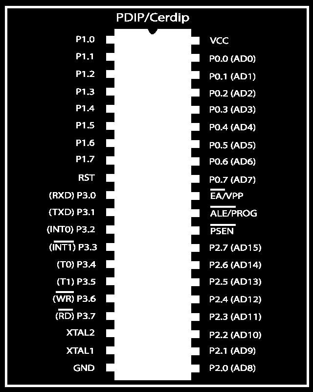
46 PIN DIAGRAM 9
47 PIN CONFIGURATION ALE/PROG-: when this pin is high it latches the low byte of the address during accesses to external memory. This pin is low during EPROM programming. PSEN-: Program Store Enable is the read strobe to external program memory. EA/VPP-: This pin is an active low pin connected to ground when microcontroller is accessing the program code stored in the external memory and connected to Vcc when it is accessing the program code in the on chip memory. 10
48 PIN CONFIGURATION RST -: applying a high pulse to this pin, the microcontroller will reset and terminate all activities. PORT 0 to 3 -: These are 8-bit bidirectional I/O port. Port 0 does not contain any internal pull-ups. Alternate function of port 3are RxD, TxD, INT0, INT1,T0,T1,WR,RD. XTAL1 & XTAL2 -: connected to oscillator amplifier. VCC-: Supply voltage. VSS-: Circuit ground potential. 11


49 MEMORY ORGANISATION Code Memory. External RAM. On-Chip Memory. Internal RAM. Special Function Register. Machine Cycle. 12
50 Code Memory holds the actual 8051 program. limited to 64K. may be both internal or external. slow accessing speed. it gains in quantity. limited to 64K. External RAM 13
51 On-Chip Memory It refers to that memory that physically exists on the microcontroller itself. Two typesa) Internal RAM. b) SFR(Special Function Register.) Total 256 bytes. Equal memory for RAM and SFR i,e 128bytes. 14


52 15
53 SPECIAL FUNCTION REGISTER Accumulator. B Register. Program Status Word. Stack Pointer. Data Pointer. Ports 0 to 3. Timer Registers. Control Register. 16
54 +5 VOLT POWER SUPPLY 17
55 SWITCH INTERFACING 18
56 LED INTERFACING 19

57 7 SEGMENT INTERFACING 20
58 LCD INTERFACING 21

59 RELAY INTERFACING 22


60 ADC INTERFACING 23

61 MATRIX KEYPAD INTERFACING 24
62 APPLICATION OF 8051 Automobile. Rail Transport. Industrial Processing. Remote sensing. Robotics. Consumer electronics. Security(e-commerce and smart cards). Medical. Defense application. 25

63 26
QUESTION BANK III YEAR / V SEM CONTROL OF ELECTRICAL MACHINES UNIT I CONTROL CIRCUIT COMPONENTS PART - A
 PERIYAR CENTENARY POLYTECHNIC COLLEGE Periyar Nagar, Vallam 613 403, Thanjavur AUTONOMOUS INSTITUTION DEPARTMENT OF ELECTRICAL AND ELECTRONICS ENGINEERING QUESTION BANK III YEAR / V SEM CONTROL OF ELECTRICAL
Basic Electricity. Mike Koch Lead Mentor Muncie Delaware Robotics Team 1720 PhyXTGears. and Electronics. for FRC
 Basic Electricity and Electronics for FRC Mike Koch Lead Mentor Muncie Delaware Robotics Team 1720 PhyXTGears The Quick Tour The Analog World Basic Electricity The Digital World Digital Logic The Rest
Maximum Demand Control using Microcontroller AT89c51
 IOSR Journal of Electrical and Electronics Engineering (IOSR-JEEE) e-issn: 2278-1676,p-ISSN: 2320-3331, PP 18-23 www.iosrjournals.org Maximum Demand Control using Microcontroller AT89c51 Apurva A. Bhagwat
TRI-SERVICE ELECTRICAL WORKING GROUP (TSEWG) 03/05/09 TSEWG TP-11: UFC N BEST PRACTICES
 03/05/09 TSEWG TP-11: UFC N BEST PRACTICES") TSEWG TP-11: UFC 3-500-10N BEST PRACTICES UFC 3-500-10N was developed by NAVFAC and was used as the starting point for the tri-services development of UFC 3-500-10, Design: Electrical Engineering. UFC
TSEWG TP-11: UFC 3-500-10N BEST PRACTICES UFC 3-500-10N was developed by NAVFAC and was used as the starting point for the tri-services development of UFC 3-500-10, Design: Electrical Engineering. UFC
A system fault contribution of 750 mva shall be used when determining the required interrupting rating for unit substation equipment.
 General Unit substations shall be 500 kva minimum, 1500 kva maximum unless approved otherwise by the University. For the required configuration of University substations see Standard Electrical Detail
Earthing UNIT. Learning Objectives. Introduction. To understand purpose of Earthing. To learn system of earthing.
 274 Electrical Technician UNIT 10 Earthing Learning Objectives To understand purpose of Earthing. To learn system of earthing. Introduction The very purpose of earthing is to safe against dangers of shock
Solar tracker is the best solution for receiving maximum radiation.
 1 Definition of problem Market Solution Introduction Block diagram Circuit diagram Components Software/Hardware used Feasibility Application Future enhancement Work distribution of project Reference Queries
International Journal of Science Engineering and Advance Technology, IJSEAT, Vol 3, Issue 9 ISSN September-2015
 Design and implementation of Traffic Flow based Street Light Control System with effective utilization of solar energy M.Abhishek, Syed ajram shah, K.Chetan, K.Arun kumar B.Tech Students EEE Department
REVISION HISTORY REVISION HISTORY
 FILTER CONTROLLER REVISION HISTORY Filter Flush Controller forms part of the Netafim range of filtration controllers all designed to make filteration more reliable and economical.. Contact any of the Netafim
SDM72 Start on Demand Modules
 Capricorn Controls DA04SDM72-2 Revised Design Page 1 of 6 SDM72 Start on Demand Modules Genset Controls - Timers - Monitors - Trips - Battery Charging - Spares & Accessories - Custom Products Application
UBC Technical Guidelines Section Edition Commissioning of Electrical Systems Page 1 of 5
 Page 1 of 5 1.0 GENERAL 1.1 Coordination Requirements.1 UBC Building Operations Electrical Technical Support.2 UBC Energy & Water Services 2.0 REQUIREMENTS FOR COMMISSIONING AND TESTING 2.1 Testing.1 Unit
Earthing. PowerPoint Presentation, Markers and Whiteboard
 Session: Earthing Learning Objective Explain the process of earthing and testing the earth resistance Evaluation Criterion Interactive Questioning Duration Resources Facilitator s Notes 30 Minutes PowerPoint
POWER PROFET A simpler solution with integrated protection for switching high-current applications efficiently & reliably
 CONTENTS 2 Efficient Alternative 4 Diagnosis and Protection 6 3 Integrated Protection 6 Switching Cycles 7 Power Loss Reduction Improved Power Protection POWER PROFET A simpler solution with integrated
OPERATING AND MAINTENANCE MANUAL. Primary Current Injection Test Set. 750ADM-H mk2
 OPERATING AND MAINTENANCE MANUAL Product: Type: Primary Current Injection Test Set 750ADM mk2 750ADM-H mk2 DESIGNED AND MANUFACTURED BY: T & R Test Equipment Limited 15-16 Woodbridge Meadows, Guildford,
1 Introduction. 2 Cranking Pulse. Application Note. AN2201/D Rev. 0, 11/2001. Low Battery Cranking Pulse in Automotive Applications
 Application Note Rev. 0, 11/2001 Low Battery Cranking Pulse in Automotive Applications by Axel Bahr Freescale Field Applications Engineering Munich, Germany 1 Introduction 2 Cranking Pulse Electronic modules
Te 803 Electronic Controller. Service, Operation & Technical Information Manual
 Te 803 Electronic Controller Service, Operation & Technical Information Manual WARNING! Technical descriptions and data given in this document are accurate, to the best of our knowledge, but can be subject
GS Series. with new controller SM30
 GS Series Sensorpress Booster Systems with new controller SM30 GS Series The GS range of fixed speed booster setsincludes models with 2 to 3 electric service pumps, and an additional jockey pump able to
International Journal of Advance Engineering and Research Development
 Scientific Journal of Impact Factor (SJIF): 5.71 e-issn (O): 2348-4470 p-issn (P): 2348-6406 International Journal of Advance Engineering and Research Development Volume 5, Issue 05, May -2018 SPEED SYNCHRONIZATION
Cat/DCG-6D1I/07-08/03/Ver 1 Page 2/10
 Cat/DCG-6D1I/07-08/03/Ver 1 Page 2/10 Index 1.1 Introduction 1.2 Salient Feature of the DGC-6D 1.2.1 Protection & Supervision 1.2.2 Measurement & Display 1.2.3 LED Indications 1.2.4 Timer 1.3 Function
NanoPower P31u / P31uX Datasheet Electric Power System for mission critical space applications with limited resources
 NanoPower P31u / P31uX Datasheet Electric Power System for mission critical space applications with limited resources 1 Table of Contents 1 TABLE OF CONTENTS... 2 2 OVERVIEW... 3 2.1 HIGHLIGHTED FEATURES...
THE BEST ELECTRICAL CONTROLS BUSINESS ON THE PLANET! Unmatched Service Superior Product Quality Advantage Pricing
 Introduction A contactor is an electrical device which is used for switching an electrical circuit on or off. It is considered to be a special type of relay. However, the basic difference between the relay
TECHNICAL DATA SHEET INFINITY kva 3Ph(in) 3Ph(out)
 3Ph(out)") TECHNICAL DATA SHEET INFINITY 3300 10 15 20 kva 3Ph(in) 3Ph(out) GENERAL INFORMATION POWER - kva 10 15 20 UPS typology ON LINE Double conversion ACTIVE stand by-operation (Optional) Nominal output power
TECHNICAL DATA SHEET INFINITY 3300 10 15 20 kva 3Ph(in) 3Ph(out) GENERAL INFORMATION POWER - kva 10 15 20 UPS typology ON LINE Double conversion ACTIVE stand by-operation (Optional) Nominal output power
MANUAL TROUBLESHOOTING. ECM Motor. ECM / ECM-DX Series. v100 Issue Date: 08/15/ Price Industries Limited. All rights reserved.
 MANUAL ECM Motor ECM / ECM-DX Series v100 Issue Date: 08/15/17 2017 Price Industries Limited. All rights reserved. ECM MOTOR TABLE OF CONTENTS ECM Motor Background...1 ECM Motor Power and Control Connectors...2
Mar H: SUPPLEMENTAL PARALLELING GEAR (16315-H)
") 2101 Commonwealth Blvd, Suite B Ann Arbor, MI 48105-5759 www.med.umich.edu/facilities/plan/ 263010-H: SUPPLEMENTAL PARALLELING GEAR (16315-H) Related Sections Basis Guideline: N/A For an explanation of
2101 Commonwealth Blvd, Suite B Ann Arbor, MI 48105-5759 www.med.umich.edu/facilities/plan/ 263010-H: SUPPLEMENTAL PARALLELING GEAR (16315-H) Related Sections Basis Guideline: N/A For an explanation of
825-P Modular Protection System for motors Specification Guide
 Specification Guide 1.0 General 1.01 The motor protection relay shall have a current operating range of 0.5 and 5000 amperes. 1.02 The motor protection relay shall provide current measurement-based protection
ELECTRIC POWER AND HOUSEHOLD CIRCUITS
 ELECTRIC POWER AND HOUSEHOLD CIRCUITS HEATING EFFECT OF CURRENT Heating effect of electricity is one of the widely-used effects in the world. When electric current is passed through a conductor, it generates
Comparison of Indian Electricity Rules, 1956 Vs CEA (Measures relating to Safety and Electric Supply) Regulations, 2010
 Regulations, 2010") 1 of 5. Comparison of Indian Electricity Rules, 1956 Vs CEA (Measures relating to Safety and Electric Supply) Regulations, 2010 2 Definitions 2 Not seen the definition for Inspector. But with, - Qualifications,
1 of 5. Comparison of Indian Electricity Rules, 1956 Vs CEA (Measures relating to Safety and Electric Supply) Regulations, 2010 2 Definitions 2 Not seen the definition for Inspector. But with, - Qualifications,
Electrical Control System Components Basics of Magnetic Control :
 Electrical Control System Components Basics of Magnetic Control : Dr.M.S.Narkhede, LEE, GP Mumbai 1 Contact Types : Contacts are classified into different ways as follows. According to applications contacts
Case Study on On EHV Circuit Breaker Flashover NTPC-SINGRAULI
 Case Study on On EHV Circuit Breaker Flashover AUTHORS: B. K. SINGH (AGM-ELECT) S.C.SINGH (SUPDT-ELECT) MANOJ SHARMA (Dy SUPDT-ELECT) ANAND PANDEY (ENGR-ELECT) BREAKER-FLASHOVER There has been a rising
HIGH SENSITIVE ALCOHOL SENSOR WITH AUTO CAR IGNITION DISABLE FUNCTION
 HIGH SENSITIVE ALCOHOL SENSOR WITH AUTO CAR IGNITION DISABLE FUNCTION K.S.SAI MANIKANTA SWARNANDHRA INSTITUTE OF ENGINEERING AND TECHNOLOGY,NARSAPUR ABSTRACT The main aim of this embedded application is
Technical Specification SENTINEL PRO
 Technical Specification SENTINEL PRO Contents 1 GENERAL DESCRIPTION... 3 1.1 Main features of the UPS unit... 4 1.2 Standard Versions... 4 1.3 ER Versions for extended autonomy... 4 2 SENTINEL PRO SERIES
International Journal of Advance Engineering and Research Development
 Scientific Journal of Impact Factor (SJIF): 4.72 International Journal of Advance Engineering and Research Development Volume 4, Issue 6, June -2017 e-issn (O): 2348-4470 p-issn (P): 2348-6406 POWER GENERATION
UAV EFI components In miniature sizes
 UAV EFI components In miniature sizes For small 2 and 4 stroke engines in 20cc- 200cc ranges V1.5 ECOTRONS LLC 2016/1 Copyright Ecotrons All rights reserved Contents 1. UAV EFI System Overview... 2 1.1
Contents. Preface... xiii Introduction... xv. Chapter 1: The Systems Approach to Control and Instrumentation... 1
 Contents Preface... xiii Introduction... xv Chapter 1: The Systems Approach to Control and Instrumentation... 1 Chapter Overview...1 Concept of a System...2 Block Diagram Representation of a System...3
Technical Specifications. Sentinel PRO 700 VA up to 3000 VA 1000 VA ER-2200 VA ER-3300 VA ER
 Technical Specifications Sentinel PRO 700 VA up to 3000 VA 1000 VA ER-2200 VA ER-3300 VA ER Sentinel PRO CONTENTS 1. GENERAL DESCRIPTION... 2 1.1. Main features of the UPS unit... 3 1.2. Standard Versions...
Week 11. Module 5: EE100 Course Project Making your first robot
 Week 11 Module 5: EE100 Course Project Making your first robot Dr. Ing. Ahmad Kamal Nasir Office Hours: Room 9-245A Tuesday (1000-1100) Wednesday (1500-1600) Course Project: Wall-Follower Robot Week 1
1. Historical background of I2C I2C from a hardware perspective Bus Architecture The Basic I2C Protocol...
 Table of contents CONTENTS 1. Historical background of I2C... 16 2. I2C from a hardware perspective... 18 3. Bus Architecture... 22 3.1. Basic Terminology... 23 4. The Basic I2C Protocol... 24 4.1. Flowchart...
Working Principle of Earth Leakage Circuit Breaker (ELCB) and Residual Current Device (RCD)
 and Residual Current Device (RCD)") Working Principle of Earth Leakage Circuit Breaker (ELCB) and Residual Current Device (RCD) Schneider Electric RCBO Earth Leakage Circuit Breaker (ELCB) An Earth Leakage Circuit Breaker (ELCB) is a device
Working Principle of Earth Leakage Circuit Breaker (ELCB) and Residual Current Device (RCD) Schneider Electric RCBO Earth Leakage Circuit Breaker (ELCB) An Earth Leakage Circuit Breaker (ELCB) is a device
SALES PRESENTATION FOR RELAYS, CONTACTORS & MOTOR STARTER TESTING EQUIPMENTS
 SALES PRESENTATION FOR RELAYS, CONTACTORS & MOTOR STARTER TESTING EQUIPMENTS Relay Test Bench: LIST OF TEST EQUIPMENT 1. FIVE STATION BIMETAL OVERLOAD RELAY TEST BENCH 2. TWENTY FOUR STATION RELAY HEATING
This Datasheet for the IC670MDL930. Relay 2A 8 Pt. 6 form A/2 form C Isolated.
 This Datasheet for the IC670MDL90 2A 8 Pt. 6 form A/2 form C Isolated http://www.qualitrol.com/shop/p-142-ic670mdl90.aspx Provides the wiring diagrams and installation guidelines for this GE Field Control
Title Low Voltage Distribution and Installations Earthing References and Definitions. Reference Number PDS 03 (ARTC Standard: EP SP)
") Discipline Engineering Standard NSW Category Electrical Title Low Voltage Distribution and Installations Earthing References and Definitions Reference Number PDS 03 (ARTC Standard: EP 12 00 00 02 SP) Document
Discipline Engineering Standard NSW Category Electrical Title Low Voltage Distribution and Installations Earthing References and Definitions Reference Number PDS 03 (ARTC Standard: EP 12 00 00 02 SP) Document
[You may download this article at: https://fluidsys.org/downloads/ ]
![[You may download this article at: https://fluidsys.org/downloads/ ]](/thumbs/75/72588514.jpg "[You may download this article at: https://fluidsys.org/downloads/ ]") Fluidsys Training Centre, Bangalore offers an extensive range of skill-based and industry-relevant courses in the field of Pneumatics and Hydraulics. For more details, please visit the website: https://fluidsys.org
Fluidsys Training Centre, Bangalore offers an extensive range of skill-based and industry-relevant courses in the field of Pneumatics and Hydraulics. For more details, please visit the website: https://fluidsys.org
Table of Contents 文管中心 發行章
 ST600-XXX Series Pure Sine Wave Power Inverter User s Manual Table of Contents 1. Important Safety Instructions 1-1 General Safety Precautions 1 1-2 Battery Precautions. 1 2. Basic Descriptions 2-1 Mechanical
ELECTRICIAN S THEORY EXAMINATION 11 September 2010 QUESTION AND ANSWER BOOKLET
 Candidate Code No. ET36 For Board Use Only Result Date Int Result Date Int ELECTRICIAN S THEORY EXAMINATION 11 September 2010 QUESTION AND ANSWER BOOKLET INSTRUCTIONS READ CAREFULLY Time Allowed: Three
TECHNICAL DATA SHEET KVA UPS Systemss
 Återförsäljare: Tre Röda AB TillingeHagby 7-745 94 ENKÖPING Tel: 08-560 200 22 e-post: info@treroda.nu http: www.treroda.nu When the INSIDE is important make the OUTSIDE Cannon TECHNICAL DATA SHEET 400-500-600-800
SM361 RIG SWITCH CONSTRUCTION MANUAL
 SM361 RIG SWITCH CONSTRUCTION MANUAL Document ver 1, For software release ver 1.1 May 27, 2016 Controls the power of 12V equipment while a vehicle is in use Product Development by: SM361 RIG SWITCH OVERVIEW
Electrical Protection
 Electrical Protection Excessive current in any electrical circuit is hazardous and not desired, and these maybe caused by the following; 1. Overloads, and 2. Short-circuits. Overload Currents: These are
RVS-DX Digital Reduced Voltage Motor Starter
 RVS-DX Digital Reduced Voltage Motor Starter Specification Guide Specification Guide Contents 1.0 Introduction 2.0 Specifications 2.1 Standard Performance Features 2.2 Standard Protection Features 2.3
World Class Power Solutions. Rectifiers. For Stationary Battery Systems in Nuclear Power Plants
 World Class Power Solutions Rectifiers For Stationary Battery Systems in Nuclear Power Plants General 2 1.1 Application Electronically controlled rectifier assemblies are used in conjunction with suitable
Chapter 17 Notes. Magnetism is created by moving charges.
 Chapter 17 Notes Section 17.1 Electric Current and Magnetism Hans Christian Øersted (1819), a Danish physicist and chemist - compass needle near a wire circuit and with current flowing through the wire,
Starters. Overview. Siemens caters with following types of starters to agricultural and industrial sector.
 Starters Overview Siemens caters with following types of starters to agricultural and industrial sector. 55 Application The main purpose of motor starters is to start the electrical motor by switching
Government Polytechnic Muzaffarpur Name of the Lab: Electric Traction-II Lab
 Government Polytechnic Muzaffarpur Name of the Lab: Electric Traction-II Lab Subject Code: 1620609A Experiment-1 Aim: Study of various traction systems. Theory: A traction system is of mainly two type
ELECTRICAL INSTALLER EXAMINATION 18 November 2017 QUESTION AND ANSWER BOOKLET
 Candidate Code No. EIN15 For Board Use Only Result Date Int Result Date Int ELECTRICAL INSTALLER EXAMINATION 18 November 2017 QUESTION AND ANSWER BOOKLET INSTRUCTIONS READ CAREFULLY Time Allowed: Three
Electronic. Why use an electronic system?
 Electronic Why use an electronic system? Today the requirement are much higher than for a number of years ago. There are both legal requirements and the wishes of the customer about. As little harmful
HGM1780. Automatic Genset Controller USER MANUAL. Smartgen Technology
 HGM1780 Automatic Genset Controller USER MANUAL Smartgen Technology Smartgen Technology Co., Ltd No. 28 Jinsuo Road Zhengzhou Henan Province P. R. China Tel: 0086-371-67988888/67981888 0086-371-67991553/67992951
Power systems Protection course
 Al-Balqa Applied University Power systems Protection course Department of Electrical Energy Engineering Dr.Audih 1 Part 3 Protective Devices Fuses & Circuit Breakers 2 Introduction: Fuse Is advice used
CLP POWER HONG KONG LIMITED. SUPPLY RULES March 2001
 CLP POWER HONG KONG LIMITED SUPPLY March 2001 ADVISORY SERVICE Advice concerning matters relating to the supply of electricity may be obtained free of charge from the Company. OTHER COMPANY PUBLICATIONS
DESIGN CONSIDERATIONS FOR APPLICATION OF SHUNT CAPACITORS IN HEAVY HATER PLANT (TUTICORIN)
") DESIGN CONSIDERATIONS FOR APPLICATION OF SHUNT CAPACITORS IN HEAVY HATER PLANT (TUTICORIN) -A.R. Subraaanian -R.A.A. Palani -J. Thomson A new 3.3 K.V. 4200 KVAR auto switching capacitor bank has been installed
DESIGN CONSIDERATIONS FOR APPLICATION OF SHUNT CAPACITORS IN HEAVY HATER PLANT (TUTICORIN) -A.R. Subraaanian -R.A.A. Palani -J. Thomson A new 3.3 K.V. 4200 KVAR auto switching capacitor bank has been installed
Gate & Door Controller with LCD and Intelligent Technology
 2nd Edition Gate & Door Controller with LCD and Intelligent Technology 24Sv1 and 12Sv1 Motor Controllers Setup and Technical information for single motor controller for gates & doors Includes latest Intelligent
Short form catalogue. Motor protection & control
 Short form catalogue Star Series Motor protection & control Motor Protection and Control up to 25 HP / 600 VAC Overview...2 Contactors and Overload Relays...11 4-pole Contactors...41 Control Relays...59
DuraWatt DS12VD 140-Watt DC-DC 12 Volt Power Supply Short Form User Manual Version 1.0. Table of Contents
 DuraWatt DS12VD 140-Watt DC-DC 12 Volt Power Short Form User Manual Version 1.0 Table of Contents 1. Getting Started...1 1.1. Introduction...1 1.2. Product Photo...2 1.3. Block Diagram...2 1.4. Included
ADS7 AC Contactor Starters
 ADS7 AC Contactor Starters ADS7 starters fully comply with BS EN 60947-4-1, IEC 60947-4-1 and VDE 0660. The range offers a multitude of configurations and optional features including a complete choice
DS1230Y/AB 256k Nonvolatile SRAM
 www.maxim-ic.com FEATURES 10 years minimum data retention in the absence of external power Data is automatically protected during power loss Replaces 32k x 8 volatile static RAM, EEPROM or Flash memory
Class X Chapter 09 Electrical Power and Household circuits Physics
 EXERCISE- 9 (A) Question 1: Write an expression for the electrical energy spent in flow of current through an electrical appliance in terms of current, resistance and time. Solution 1: Electrical energy,
* With I-Option card only (C. T. connection) Basic connections with isolated contacts
 Basic connections with isolated contacts") Typical Circuit Diagrams. Typical Circuit Diagrams Basic connections with isolated contacts F2 - Overload relay Q1 - MPCB / ACB / MCCB /K2 - Main isolating contactors (AC-3 rated) F3 - Semiconductor Fuses
Typical Circuit Diagrams. Typical Circuit Diagrams Basic connections with isolated contacts F2 - Overload relay Q1 - MPCB / ACB / MCCB /K2 - Main isolating contactors (AC-3 rated) F3 - Semiconductor Fuses
Product Guide: Series III Pump Control Board Set (RoHS)
") revised 04/08/10 Description: The Series III Pump Control Board Set provides motor drive and pump control for a wide assortment of pumps from Scientific Systems, Inc. The assembly consists of two circuit
revised 04/08/10 Description: The Series III Pump Control Board Set provides motor drive and pump control for a wide assortment of pumps from Scientific Systems, Inc. The assembly consists of two circuit
AQUASTAR C6. (Comfort 6000) Next Generation Auto Backwash Valve System. (selectable time-pressure or remote cycle start)
 Next Generation Auto Backwash Valve System. (selectable time-pressure or remote cycle start)") AQUASTAR C6 (Comfort 6000) Next Generation Auto Backwash Valve System (selectable time-pressure or remote cycle start) SIDE MOUNTED AND TOP MOUNTED VALVES WITH QUICK INSTALL ELECTRIC ACTUATORS FOR PIPE
AQUASTAR C6 (Comfort 6000) Next Generation Auto Backwash Valve System (selectable time-pressure or remote cycle start) SIDE MOUNTED AND TOP MOUNTED VALVES WITH QUICK INSTALL ELECTRIC ACTUATORS FOR PIPE
UAV engine EFI components Specifications Manual
 UAV engine EFI components Specifications Manual -In miniature sizes - For 20cc to 300cc engines V1.7 COPY RIGHTS ECOTRONS LLC ALL RIGHTS RESERVED Http://www.ecotrons.com Note: If you are not sure about
ECET Distribution System Protection. Overcurrent Protection
 ECET 4520 Industrial Distribution Systems, Illumination, and the NEC Distribution System Protection Overcurrent Protection One of the most important aspects of distribution system design is system protection.
Functions provided by measuring relays in railway equipment
 Functions provided by measuring relays in railway equipment 1-Current relays -Minimum current relays (During normal operation, if the current is present these relays are in operating position and switch
VALVE CONTROLLERS Controllers for Dust Extr 2010 / 2011 action Technology
 VALVE CONTROLLERS Controllers for Dust Extraction 2010 Technology / 2011 Valve controllers for all cases HESCH has the skills and technology to tackle any control task for dedusting of filter and dust
Timer Relays - Fixed & Adjustable
 Solid State Solid State relays are suitable across all applications where reliability is paramount. Unlike conventional relays, Solid State relays use electronics in place of traditional contacts, allowing
Michigan State University Construction Standards SECONDARY UNIT SUBSTATIONS PAGE
 PAGE 261116-1 SECTION 261116 PART 1 - GENERAL 1.1 RELATED DOCUMENTS A. Drawings and general provisions of the Contract, including General and Supplementary Conditions and Division 01 Specification Sections,
Power Distribution System User s Manual. Model: PDS-100
 Power Distribution System User s Manual Model: PDS-0 Section Page Product Overview... 1 I) General Information... 2 II) Important Safety Information... 2 III) Installation... 3 A) Materials Provided...
Fuse state indicator MEg72. User manual
 Fuse state indicator MEg72 User manual MEg Měřící Energetické paráty, a.s. 664 31 Česká 390 Czech Republic Fuse state indicator MEg72 User manual Fuse state indicator MEg72 INTRODUCTION The fuse state
Continuing Education Course #206 Introduction to Designing Machine Control Systems Part 2
 1 of 5 Continuing Education Course #206 Introduction to Designing Machine Control Systems Part 2 1. Continuing to answer the following questions indicates that you understands that the presented material
Parker AC10 Frequency Inverter (to 22kW) Easy Start Guide
 Easy Start Guide") Parker AC10 Frequency Inverter (to 22kW) Easy Start Guide CAUTION: 1)Do not re-set while the motor is rotating 2)Perform parts replacement after discharge is finished 3)Do not connect output terminals
Parker AC10 Frequency Inverter (to 22kW) Easy Start Guide CAUTION: 1)Do not re-set while the motor is rotating 2)Perform parts replacement after discharge is finished 3)Do not connect output terminals
CENTRIFEEDER ELECTRONICS
 CENTRIFEEDER ELECTRONICS FOR USE WITH CENTRIFEEDER with Integrated Vibratory Control REV 08/13 ADDENDUM VERSION 6.22 SOFTWARE Copyright 2011 Eastern Instrument Laboratories, Inc. All Rights Reserved. TABLE
ACSI MODEL 1406BB-04-AO POWER SUPPLY INSTALLATION INSTRUCTIONS
 II 1400-10 ACSI MODEL 1406BB-04-AO POWER SUPPLY INSTALLATION INSTRUCTIONS Features: Up to 1.95 Amps Load Capacity Class 2 Rated Outputs Overload, Over Voltage, and Short Circuit Protection Standby Battery
FUNDAMENTALS OF POWER DISTRIBUTION SAIEE-1337-V : 2 CPD credits : Category 1
 THE SOUTH AFRICAN INSTITUTE OF ELECTRICAL ENGINEERS FUNDAMENTALS OF POWER DISTRIBUTION SAIEE-1337-V : 2 CPD credits : Category 1 OVERVIEW : 1. Introduction to Distribution, Transmission and Generation
ISSN: [Vignesh* et al., 7(1): January, 2018] Impact Factor: 5.164
![ISSN: [Vignesh* et al., 7(1): January, 2018] Impact Factor: 5.164](/thumbs/85/92118178.jpg "ISSN: [Vignesh* et al., 7(1): January, 2018] Impact Factor: 5.164") ISSN: -9 [Vignesh* et al., (): January, 08] Impact Factor:. IJESRT INTERNATIONAL JOURNAL OF ENGINEERING SCIENCES & RESEARCH TECHNOLOGY ELECTRONIC BRAKE ASSIST SYSTEM (EBAS) IN AUTOMOBILE WITH WIRE BRAKE
ISSN: -9 [Vignesh* et al., (): January, 08] Impact Factor:. IJESRT INTERNATIONAL JOURNAL OF ENGINEERING SCIENCES & RESEARCH TECHNOLOGY ELECTRONIC BRAKE ASSIST SYSTEM (EBAS) IN AUTOMOBILE WITH WIRE BRAKE
RVS-DN Digital Reduced Voltage Motor Starter
 RVS-DN Digital Reduced Voltage Motor Starter Specification Guide Specification Guide Contents 1.0 Introduction 2.0 Specifications 2.1 Standard Performance Features 2.2 Standard Protection Features 2.3
SDS Enclosed Star-Delta Starter User Guide
 SDS Enclosed Star-Delta Starter User Guide (7.5kW~90kW) V2.0.0 PLEASE NOTE: AS STANDARD AND UNLESS OTHERWISE SPECIFIED, THIS PRODUCT IS EQUIPPED WITH A BASIC LOW INTEGRITY EMERGENCY STOP CIRCUIT STOPPING
DS1250W 3.3V 4096k Nonvolatile SRAM
 19-5648; Rev 12/10 3.3V 4096k Nonvolatile SRAM www.maxim-ic.com FEATURES 10 years minimum data retention in the absence of external power Data is automatically protected during power loss Replaces 512k
Title High Voltage and 1500 System Earthing References and Definitions. Reference Number PDS 02 (RIC Standard: EP SP)
") Discipline Engineering Standard NSW Category Electrical Title High Voltage and 1500 System Earthing References and Definitions Reference Number PDS 02 (RIC Standard: EP 12 00 00 01 SP) Document Control
Discipline Engineering Standard NSW Category Electrical Title High Voltage and 1500 System Earthing References and Definitions Reference Number PDS 02 (RIC Standard: EP 12 00 00 01 SP) Document Control
TRANSMISSION SYSTEMS
 TRANSMISSION SYSTEMS Transmitting large amounts of electric energy over long distances is accomplished most efficiently by using high-voltages. Without transformers the widespread distribution of electric
Thermal Circuit Breaker 3120-F...
 Description The 320 circuit breaker/switch combination is an ON/OFF switch with integral overcurrent protection (S-type TO CBE to EN/IEC 60934). The trip element is a bimetal. Type 320 is ideally suited
INSTALLATION INFORMATION
 INSTALLATION INFORMATION BMS ZE6000i-PCBT.xxxx / ver. 2 Programmable battery management system for Lithium Ion battery cells, for up to 32 round or prismatic cells, 10 to 400Ah NOTE: This installation
Standby Power Systems
 Source: Power Quality in Electrical Systems Chapter 13 Standby Power Systems The term standby power systems describes the equipment interposed between the utility power source and the electrical load to
AIR COOLED RECTIFIER SPECIFICATION S-50-A
 SPECIFICATIONS AIR COOLED RECTIFIER Spec50a1 5JAN1999 SPECIFICATION S-50-A HIGH VOLTAGE SINGLE TRANSFORMER AIR COOLED RECTIFIER Standard output power range: 250 to 600 volts at 100 to 1,200 amperes TECHNICAL
Push buttons are of two types i) Momentary push button ii) Maintained contact or detent push button
 Momentary push button ii) Maintained contact or detent push button") ELECTRO-PNEUMATIC Push button switches A push button is a switch used to close or open an electric control circuit. They are primarily used for starting and stopping of operation of machinery. This causes
ELECTRO-PNEUMATIC Push button switches A push button is a switch used to close or open an electric control circuit. They are primarily used for starting and stopping of operation of machinery. This causes
PEOPLE ARE FAMILIAR WITH THE CONCEPT OF RUNNING A LIGHT FROM A BATTERY AND THEN RECHARGING THE BATTERY USING A SOLAR PANEL OR A WIND-POWERED GENERATOR
 A Perpetual Light PEOPLE ARE FAMILIAR WITH THE CONCEPT OF RUNNING A LIGHT FROM A BATTERY AND THEN RECHARGING THE BATTERY USING A SOLAR PANEL OR A WIND-POWERED GENERATOR. HOWEVER, WE REALLY WANT TO BE ABLE
4 Electric Circuits. TAKE A LOOK 2. Identify Below each switch, label the circuit as a closed circuit or an open circuit.
 CHAPTER 17 4 Electric Circuits SECTION Introduction to Electricity BEFORE YOU READ After you read this section, you should be able to answer these questions: What are the three main parts of a circuit?
Installation Manual for DC Injection Brake Units
 Power Drive Services INJ Series DC brake modules PDS 11-30-100A Page 1 of 17 Issue 15 Contents. 1. Safety. 2. Installation. 3. Setting Up. 4. Wiring Diagrams. 5. Specifications. 6. Selection. 7. Timing
Submersible Turbine Pump (Volute) STM type (T, TU, and TU3) SSTM type (TUA)
 STM type (T, TU, and TU3) SSTM type (TUA)") Instruction Manual Installation Manual Submersible Turbine Pump (Volute) STM type (T, TU, and TU3) SSTM type (TUA) Thank you for your purchase of Teral (Volute) Submersible Turbine Pump. To the customers
Instruction Manual Installation Manual Submersible Turbine Pump (Volute) STM type (T, TU, and TU3) SSTM type (TUA) Thank you for your purchase of Teral (Volute) Submersible Turbine Pump. To the customers
Modular Standardized Electrical and Control Solutions for Fast Track Projects
 Modular Standardized Electrical and Control Solutions for Supporting fast track projects ABB is the leading supplier of electrical and control equipment for power plants. The company offers a comprehensive
SECTION MOTOR CONTROL
 SECTION 26 24 19 MOTOR CONTROL PART 1 - GENERAL 1.1 SECTION INCLUDES A. Manual motor starters B. Magnetic motor starters C. Combination magnetic motor starters D. Solid-state reduced voltage motor starters
Magnetek DSD 412 Drive
 DRIVE STARTUP MANUAL Magnetek DSD 412 Drive Induction Motor Installation www.smartrise.us 2601 Fair Oaks Blvd., Sacramento, CA 95864 916.457.5129 Magnetek DSD 412 Drive EQUIPMENT/SETTINGS VERIFICATION
KD LV Motor Protection Relay
 1. Protection Features KD LV Motor Protection Relay Overload (for both cyclic and sustained overload conditions) Locked rotor by vectorial stall Running stall / jam Single phasing / Unbalance Earth leakage
Crane and Hoist Solution Guide. The Advantage of Experience
 Crane and Hoist Solution Guide The Advantage of Experience Schneider Electric s Application Centers Quality Operation Guarantee Customer satisfaction is a priority for Schneider Electric and for this reason