Professional Wireless Products
|
|
|
- Rosamund Ross
- 5 years ago
- Views:
Transcription

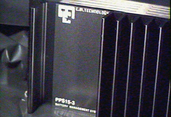


1 Page 1 of Communications Power Supply and Battery Management Controller
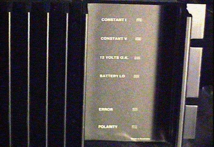
2 Page 2 of Introduction The is a 13.8 volt 15amp transformer isolated switch mode down converter designed to be used either as a stand alone supply or as a float style battery backed up supply when a lead acid battery is connected to its battery terminals. The was designed for wide mains voltage swings (240 +/- 20%) or (110+/- 10%) and high temperatures and vibration. The supply is rated at 60 C and has been NATA tested at 70 C at full load at a 280 volt mains. It was originally designed for railway trackside applications where such conditions apply. It is very suitable for applications where the mains supply is poorly regulated, and temperatures can be extreme. Models available are: Input Voltage 240 AC RMS or 110 AC RMS Output Current 15 amps DC out Output Voltage 13.8 V (all models) 1.1 Operation Principles 1.11 Stand Alone Supply The is constant voltage, constant current supply. When no battery is connected, the output voltage stays constant at 13.8 volts (adjustable) until the current limit (15 amps) is exceeded. The does not require a battery to be connected for normal operation and provides clean DC Battery Backed up Supply If a suitable back up battery is connected, the supply will run at its current limit until the battery is charged, that is until the constant voltage set point is reached. The current is shared between the communications load and the battery at all times, to a total of 15 amps. When the battery is charged, the stays at this set point (13.8 volts and adjustable), supplying the load current and a small trickle charge to the battery. Front panel LED indicators show the status of the supply and battery. When the battery is on charge the CONSTANT I LED is on. Within 0.1 Volt of the set point, the CONSTANT V LED comes on. The rate of rise of the terminal voltage on Lead Acid batteries is quite fast once they near full charge, so the LEDs form a reasonably accurate state of charge indicator in this mode Battery is Protected To avoid completely flattening the battery when the ac mains fail for extended periods, the isolates the load when the battery voltage (as seen at the ) drops to 11 volts. Approximately 1 volt of hysteresis is used to stop the disconnect function hunting. When the battery is disconnected in this way, a red BATTERY LO LED is lit. When the mains returns, the battery voltage rises rapidly to 12 volts, the load is reconnected automatically, and the 15 amps of available current is shared between the load and battery. A 12 VOLTS OK Led is lit. The terminal voltage rises to the set point (13.8 volts) when the battery is charged. At this point the supply goes into constant voltage mode, and the current to the battery drops off and a small trickle charge is left Load is Completely Protected Should the fail and present an over voltage condition (> 15 volts for 100uS), an independent MOSFET over voltage isolation switch isolates both battery and load from the supply, and a red ERROR LED is turned on. In the event that this over voltage is just a transient condition, the resets automatically. Should a charged back-up battery be connected with reverse polarity, the power supply and its load are disconnected automatically by a MOSFET switch, and a red POLARITY LED is connected. The resets automatically when the polarity is correct. This function operates even if load and battery connections are interchanged.
3 Page 3 of Recharge Time The time to charge a battery depends upon the average draw from the load, the battery capacity, and the current limit of the Suppose that the average continuous base station draw is 10 amps, then 5 amps (15 amps minus 10) is available on average to charge the battery. A 55 AH battery would then take about 12 hours to recover. 3.0 Mechanical The 19-inch rack mount (3RU) case is manufactured from custom extruded aluminium, anodized black. (see drawing appended). All major components mount to the front panel, which forms the heatsink. The PCB is 70-micron copper (2x normal), secured with press fitted standoffs in many places to the heatsink. The main electrolytics have multiple terminations to the PCB, and heavy parts like Ferrites are bolted to the PCB, while other parts are supported with Loctite 480 adhesive. The rear safety cover is made of laser cut stainless steel vented to allow full airflow. The is convection cooled, and provision must be made for clear airflow around the product, as some 75 watts are lost as heat at full load. The dress labels are back screen-printed polycarbonate that is strongly resistant to mechanical damage. The annunciator LEDS shine through this. Height 3RU 132 mm Depth 70 mm behind panel, plus 25mm sockets etc. Width 19" rack 432 mm Weight 7 Kg approx Mounting 4 screws, rack mount 4.0 Temperature & Product Life The design ambient is -10 to +60C. The product has been tested at 15 amps and 280-volt mains for 15 hours in a 70 C ambient, and passes with all components within their published operating maximum temperatures. (Freight Rail Corp test requirement) At a 20 C ambient, the heatsink rises < 20 C in still air at 15 amps load and 240 V mains input. Free airflow is required around the product, and any enclosure must be designed to lose 75 watts to free air. At 70 C and full load, the electrolytics used have a typical design life of >7000 hours (case temp 83 C IEC part). This rises to >140,000 hours at a 40 C continuous ambient. 5.0 Reliability The is manufactured using only well-specified and qualified high-grade commercial parts. In particular, the electrolytics are IEC long life grade with a life exceeding 140,000 hours at 40 C continuous. C.M. Technology burns in all products to eliminate turn on failures. The MTBF is calculated to be >60000 hours at 50 C. 6.0 Maintainability & Warranty The is manufactured from discrete components soldered to a double sided, through hole plated solder masked 70 micron PCB. Complete parts lists, circuit diagrams, PCB overlays and a description of the circuit operation are included in the purchase price.
4 Page 4 of General Specification Mains Input 50-60Hertz 240+/-20% (110 V available) Mains Isolation toroidal transformer to AS3108 E.T.S.A. APPROVAL No CS/1083/S.COMPLIES WITH AS , & AS Nominal Output Voltage (1 amp) adjustable Regulation (nominal mains 1-15 amps) <250 mv Constant Current Point 15 amp (20 amp) -0/+0.6 amp Hum, Noise & Ripple (15 A, 20 mhz BW) < 100mV pp < 15 mv rms Over Volts Lockout > 15.5 V +/- 0.4 V Battery Disconnect < 11.2 V +/ V Reverse Polarity protection Absolute Alarms (Optional) Floating contacts for AC Ok and DC good window, to+14.8 V DC. Temperature -10 C to 70 C at 15 amps Expected Life (40 C ambient, full load) >15 years MTBF (calculated) >60,000 50C RFI (generated and immunity) Test Standard Report No M51138X E.M.C.Technologies P/L. as EN55022 (CISPR 22 :1994) EN :1992 IEC :1991 IEC :1984 IEC :1988 N 2672 AUSTEL Certified Component No. A96/PS/ Output Connection The battery and load have separate positive and negative Anderson Power Pole connectors. The alarm terminals are via a 4 pole screw terminal connector. All are mounted upon the back panel. 9.0 Input Connection The mains input is an IEC fuse switch assembly, UL recognized. A spare fuse, (UL recognized) is contained in the input socket. Three MOVs (UL recognized) clip transients, and RFI is rejected by a DELTA mains filter. (UL recognized.). Mains isolation is by a conventional 50/60 Hz iron core toroidal transformer to AS3108 (E.T.S.A. approval CS/1083/S, PPS20 complies with AS , & AS ). This configuration gives excellent immunity from mains induced transients found in remote locations System Earth Bolt An M6 bolt is mounted to the case at the point of entry of the IEC mains input Alarms The alarms are floating contacts that are closed when the function is operating correctly. Alarm contacts for AC Mains OK and DC Power good (a Window from to volts) are provided. These are connected to a 4-pole screw terminal block on the back panel.
5 Page 5 of Principles of Operation The are a constant current, constant voltage D.C. supply. The output voltage stays constant (within the limits of regulation) until the current limit of 15 or 20 amps is reached. The supply then goes into constant current. This provides a simple means of floating a lead acid battery if required. The operation of the supply does not require the battery to be present Down Converter The mains input is transient clipped by 3 MOV s (R41-43, Circuit Diagram PPS153-2.sch appended). A Heineman fuse (3ag) switch assembly is used to isolate the mains. The fuse is removed by twisting the input toggle. A Delta RFI filter provides ~ 40 db extra RFI filtering upon the input. The mains is then transformed down to 22 Volts by the mains toroid T6. The output is rectified (Bridge D27) and then filtered by C29 & C30. High frequency inductor L2 provides further RF rejection. The resulting 32 volts DC is chopped at 100 Khz by MOSFET Q6, and flywheel diode D24, and then filtered by L1 and C16 to produce 13.8 volts DC on C16. Regulation is achieved by altering the mark space ratio of the control signal via U5, the SMPS controller Current and Voltage Settings The voltage setting is via 20 turn pot R33 ( SET VOLTS on the PCB), which is available through the mesh of the safety case. It is used to set the constant voltage point, or the end point for the battery charging voltage. This is factory set at volts. This pot adjusts the voltage feedback to U5, and is compared with the reference voltage (5.00 volts) generated by U5. The current in the down converter is sensed by current transformer T5, rectified by D25, and then a portion set by 20 turn pot R39 ( SET AMPS on the PCB) is sent to U5 for cycle by cycle current limiting. This limit is set to be 15 amps in the factory. The current pulses are integrated by L1 & C15 to make DC. This represents the constant current that is then shared between the battery and the load Charge State Indication The state of charge is indicated by the move from constant voltage (operation at the set point voltage) to constant current (battery terminal volts at less than the set point.) This is detected by comparator U6, that compares the reference voltage on pin 18, U5 to the output. The output of U6 drives two high brightness LEDS D20, 21 to show the state of charge. Transistors Q8, Q9 isolate this function when the mains is not on Over Voltage Protection Both LOAD and BATTERY terminals are switched via MOSFETS Q1 and Q3 respectively. The gates of these transistors are fed from a 24 volt charge pump, consisting of U2, diodes D3, D4 and capacitors C2 and C14. A comparator, U3, compares a separate precision reference D18, and the rail. If it should exceed 15.5 volts, the gate drive is removed and the outputs go open. LED D5 lights ( ERROR ). If this over voltage was just a transient, then the drive is re-applied Under Voltage In battery back up, the life of the battery is reduced if it is taken below 11 volts. The precision reference D18 and comparator U1 form a Schmitt Trigger with 1 volt hysteris. In operation, tripping U1 (battery <11.0 volts) removes the gate drive from Q1 and thus removes the load. The BATTERY LO led is lit. Hysterisis in the Schmitt means that the load is not re-connected until the battery reaches 12 volts. This happens almost immediately when the mains comes on, as the battery is in a (relatively) high impedance state at this time Upside Down
6 Page 6 of 6 Both the and the load are protected by Q1 and Q3 from an upside down connection of a battery to either of the LOAD or BATTERY terminals. The battery cannot be reverse charged either. Under these conditions the POLARITY LED is lit, and no power is available to the load. This protection circuit operates with or without mains being on History Revision 2.0 June 2000 Include 110 volt variant.
PPS20 COMMUNICATIONS POWER SUPPLY AND BATTERY MANAGEMENT SYSTEM
 PPS20 COMMUNICATIONS POWER SUPPLY AND BATTERY MANAGEMENT SYSTEM 2 Table of Contents Introduction:... 3 1.0: Operation Principles:... 3 1.1: Stand alone supply... 3 1.2: Backed up supply:... 3 1.3: Battery
A Caspian Technology Company all materials presented are trade mark and copyright protected by C.M.TECHNOLOGY Pty Ltd
 PPS12 230v AC to 12 VDC POWER SUPPLY WITH BATTERY MANAGER OPTION 2 Table of Contents Introduction:... 3 1.0: Input Voltage:... 4 1.1: Mains Hold Up (missing mains cycles):... 4 1.2: Mains Input:... 4 1.3:
EMERGENCY VEHICLE BATTERY MANAGER PS2024
 EMERGENCY VEHICLE BATTERY MANAGER PS2024 2 The PS2024 (Fig. 1) is designed as a on-vehicle battery charger / battery charge state monitor. While the vehicle is at its base or station, the charger is connected
Features. Description. Table of Contents
 Features Very low profile Very high efficiency (typically 90%) Single and dual output versions Input voltages from 24V to 110VDC nominal voltages from 5V to 48VDC -40 C to +71 C operation without de-rating
Dycon D2430 EN54-4 Fire Alarm Power Supply Series
 Dycon D2430 EN54-4 Fire Alarm Power Supply Series Technical Description Installation and Operating Manual Construction Product Regulation 0359-CPR-00434 Page 1 of 14 Contents 1. General... 3 1.1 Product
PREMIER POWER PACK INSTRUCTION MANUAL EN54-4 POWER SUPPLY UNIT INSTRUCTION MANUAL. GLT.MAN-138 Issue: /05/2016 N.R.P.J.
 EN54-4 POWER SUPPLY UNIT INSTRUCTION MANUAL GLT.MAN-138 CONTENTS Introduction to the Premier Power Pack PSU... 2 Changes to EN54-4 (The Fire Alarm Equipment Power Supply Standard)... 3 Indications... 4
RE-PR3-E-86&105 3-Phase Panel Mount 86 and 105kW
 Page 1 of 6 3-Phase Panel Mount 86 and 105kW Features: Benefits: 0-10Vdc, 0-5Vdc, 4-20mA or manual via potentiometer control input Over temperature protection with auto reset Enclosed panel mounting Efficient
& HIGH CURRENT DC POWER SUPPLIES INSTRUCTION MANUAL
 72-6850 & 72-6852 HIGH CURRENT DC POWER SUPPLIES INSTRUCTION MANUAL Table of Contents Introduction 2 Specification 2 Safety 4 EMC 5 Installation 6 Connections 6 Operation 7 Maintenance and Repair 8 www.tenma.com
DUAL 60V 20A POWER FLEX POWER SUPPLY INSTRUCTION MANUAL
 72-7570 DUAL 60V 20A POWER FLEX POWER SUPPLY INSTRUCTION MANUAL Table of Contents Specification 1 Safety 3 EMC 4 Installation 5 Connections 5 Operation 6 Maintenance 8 Specification General specifications
Installation Instructions
 AQU244 & AQU128 Series Installation Instructions Installation Instructions AQU244 24vdc 5A Supervised Power Supply/Charger module AQU128 12vdc 10A Supervised Power Supply/Charger module Both Mounted in
Industrial Power Supplies
 , Features Switch Mode Power Supplies for DIN-rail Mounting 6 Power Ranges with 2, 3, 6, 12, 20 and 24 A Current (24 VDC Models) Selectable 115/ 230 VAC Input Very low Ripple and Noise EMI complies with
Dycon D1532SM. EN50131/PD6662 Grade 3, 12V 2A Power Supply. Technical Description Installation and Operating Manual DYCON POWER SOLUTIONS LTD
 Dycon D1532SM EN50131/PD6662 Grade 3, 12V 2A Power Supply Technical Description Installation and Operating Manual DYCON POWER SOLUTIONS LTD Tel: +44 (0)1443 471 900 Unit A Cwm Cynon Business Park Mountain
Maintenance Manual 13 AMPERE POWER SUPPLY 19A704647P1-P3. Mobile Communications LBI-31801C
 C Mobile Communications 13 AMPERE POWER SUPPLY 19A704647P1-P3 CAUTION THESE SERVICING INSTRUCTIONS ARE FOR USE BY QUALI- FIED PERSONNEL ONLY. TO AVOID ELECTRIC SHOCK DO NOT PERFORM ANY SERVICING OTHER
Art. No. EC-315. Art. No. EC-330. Art. No. EC-340 SWITCH-MODE BATTTERY CHARGER CONTENTS IMPORTANT SAFETY PRECAUTIONS... 2
 SWITCH-MODE BATTTERY CHARGER CONTENTS IMPORTANT SAFETY PRECAUTIONS... 2 DESCRIPTION AND FEATURES... 3 CHARGING STAGES... 4 Art. No. EC-315 Art. No. EC-330 Art. No. EC-340 PROTECTIONS... 5 INSTALLATION...
MODEL ELC-12/40-CVM-D BATTERY CHARGER
 NATIONAL RAILWAY SUPPLY MODEL ELC-12/40-CVM-D BATTERY CHARGER Installing, Operating and Service Instructions for the ELC-12/40-CVM-D Solid State Charger PLEASE SAVE THESE IMPORTANT SAFETY AND OPERATING
SCR Power Controllers
 SCR Power Controllers Instruction Manual SCR POWER CONTROLLERS TABLE OF CONTENTS General Description and Specifications...1 Firing Modes....2 Installation and Wiring...4 Operation...9 Troubleshooting...15
elabtronics Voltage Switch
 elabtronics Voltage Switch Want to trigger a device when a monitored voltage, temperature or light intensity reaches a certain value? The elabtronics Voltage Switch is an incredibly easy way of doing it.
Powerterm L120C Single Output PSU/Battery Chargers Model C2199A-1 (12V/8A) or Model C2199A-2 (24V/6A)
 or Model C2199A-2 (24V/6A)") A Complete solution for small battery-backed dc instrument power systems. DATASHEET Supply 12Vdc 8A or 24Vdc 6A loads Ideal for RTU s, dataloggers, remote field instrumentation, alarm systems, etc. where
A Complete solution for small battery-backed dc instrument power systems. DATASHEET Supply 12Vdc 8A or 24Vdc 6A loads Ideal for RTU s, dataloggers, remote field instrumentation, alarm systems, etc. where
POWER SUPPLY MODEL XP-800. TWO AC VARIABLE VOLTAGES; 0-120V and 7A, PLUS UP TO 10A. Instruction Manual. Elenco Electronics, Inc.
 POWER SUPPLY MODEL XP-800 TWO AC VARIABLE VOLTAGES; 0-120V and 0-40V @ 7A, PLUS 0-28VDC @ UP TO 10A Instruction Manual Elenco Electronics, Inc. Copyright 1991 Elenco Electronics, Inc. Revised 2002 REV-I
Installation Instructions
 Installation Instructions AQU243-8C1R -8F8R -8C8R 24VDC/3.3Amp Supervised (AC & Battery) Power Supply/Charger Module, 85-264vac, 14 x 9 x 3.5" Enclosure, UL294, UL603 & UL1481 Listed AQU243 with one PDB-8C1R
EPS/ELA-Series User Manual EPS/ELA 250W
 EPS/ELA-Series User Manual EPS/ELA 250W EPS Stromversorgung GmbH Tel: +49 (0)821 570451 0 Index 3 Page: 1 Table of contents: Page 1. Features of ELA-Series... 3 1.1 Basic Functions... 3 1.2 Options...
Model Number Output Voltage Output Amps Input Range Max. Iin FL Efficiency Max Output Power
 Small 2.32 x 0.9 x 0.37 Size Constant Frequency High Typical Efficiency of 90% (12Vout) Low Output Noise 18 to 60VDC Input Voltage Range Output Over Voltage Protection Current Limit/Short Circuit Protection
150 WATT HEW SINGLE SERIES DC/DC CONVERTERS
 Features Description The 4:1 Input Voltage 150 W single HEW Series of DC/DC converters provide precisely regulated dc outputs. The output voltage is fully isolated from the input, allowing the output to
DPX30-xxSxx DC-DC Converter Module 9.5 ~ 18 VDC and 18 ~ 36 VDC and 36~ 75 VDC input; 3.3 to 28 VDC Single Output; 30 Watts Output Power
 DC-DC Converter Module 9.5 ~ 18 VDC and 18 ~ 36 VDC and 36~ 75 VDC input; 3.3 to 28 VDC Single Output; 30 Watts Output Power FEATURES NO MINIMUM LOAD REQUIRED 1600VDC INPUT TO OUTPUT ISOLATION SCREW TERMINALS
DPX30-xxDxx DC-DC Converter Module 9.5 ~ 18 VDC and 18 ~ 36 VDC and 36~ 75 VDC input; ±12 to ±15 VDC Dual Output; 30 Watts Output Power
 DC-DC Converter Module 9.5 ~ 18 VDC and 18 ~ 36 VDC and 36~ 75 VDC input; ±12 to ±15 VDC Dual Output; 30 Watts Output Power FEATURES NO MINIMUM LOAD REQUIRED 1600VDC INPUT TO OUTPUT ISOLATION SCREW TERMINALS
User Manual. Solar Charge Controller 3KW
 User Manual Solar Charge Controller 3KW 1 CONTENTS 1 ABOUT THIS MANUAL... 3 1.1 Purpose... 3 1.2 Scope... 3 1.3 SAFETY INSTRUCTIONS... 3 2 INTRODUCTION... 4 2.1 Features... 4 2.2 Product Overview... 5
DIN Rail UPS DC UPS/Battery Detection System Model: BDS-DIN-UPS Installation/Operation Manual
 DIN Rail UPS DC UPS/Battery Detection System Model: BDS-DIN-UPS 24-10 Installation/Operation Manual Table of Contents Section Page Section Page Quick Start 2 1) General Information 4 Materials Provided
Output Current Input Current Over Load VDC VDC ma ma(typ.) ma(typ.) VDC μf %
 ma(typ.) VDC μf %") Doc. EC-0093 FEATURES Industrial Standard 2"x1" Package Ultra-wide Input Range 9-36VDC, 18-75VDC, 40-160VDC I/O Isolation 3000VAC with Reinforced Insulation Operating Ambient Temp. Range -40 C to +88 C
Doc. EC-0093 FEATURES Industrial Standard 2"x1" Package Ultra-wide Input Range 9-36VDC, 18-75VDC, 40-160VDC I/O Isolation 3000VAC with Reinforced Insulation Operating Ambient Temp. Range -40 C to +88 C
DPX30-xxWDxx DC-DC Converter Module 10 ~ 40VDC, 18 ~ 75VDC input; ±12 to ±15 VDC Dual Output; 30 Watts Output Power
 DC-DC Converter Module 10 ~ 40VDC, 18 ~ 75VDC input; ±12 to ±15 VDC Dual Output; 30 Watts Output Power FEATURES NO MINIMUM LOAD REQUIRED 1600VDC INPUT TO OUTPUT ISOLATION SCREW TERMINALS FOR INPUT AND
55 Watt K Triple Series DC/DC Converters
 Features Very Low Noise, < mv P-P Maximum PCB Mounting with Optional Heat Sink or Chassis Mount Versions Efficiencies to 87 Common and Differential Mode Input Filtering Remote Sense On + Volt Output Single
Phoenix Inverter
 Manual EN Handleiding NL Manuel FR Anleitung DE Manual ES Appendix Phoenix Inverter 12 250 12 375 12 500 12 800 24 250 24 375 24 500 24 800 48 250 48 375 48 500 48 800 1. Safety instructions WARNING: ELECTRIC
DPX30-xxWSxx DC-DC Converter Module 10 ~ 40VDC, 18 ~ 75VDC input; 3.3 to 28VDC Single Output 30 Watts Output Power
 DC-DC Converter Module 10 ~ 40VDC, 18 ~ 75VDC input; 3.3 to 28VDC Single Output 30 Watts Output Power FEATURES NO MINIMUM LOAD REQUIRED 1600VDC INPUT TO OUTPUT ISOLATION SCREW TERMINALS FOR INPUT AND OUTPUT
SWITCH MODE POWER SUPPLY BASED BATTERY CHARGERS
 SWITCH MODE POWER SUPPLY BASED BATTERY SWITCH MODE POWER Features Wide input voltage tolerance High efficiency Overload, short circuit & reverse polarity protection Very low load & line regulation Output
SM361 RIG SWITCH CONSTRUCTION MANUAL
 SM361 RIG SWITCH CONSTRUCTION MANUAL Document ver 1, For software release ver 1.1 May 27, 2016 Controls the power of 12V equipment while a vehicle is in use Product Development by: SM361 RIG SWITCH OVERVIEW
Output Current Input Current Reflected Ripple. VDC VDC ma ma(typ.) ma(typ.) ma(typ.) VDC μf %
 ma(typ.) ma(typ.) VDC μf %") FEATURES Industrial Standard Quarter Brick Package Wide Input Range 43-101VDC & 66-1VDC Excellent Efficiency up to 92% I/O Isolation 3000VAC with Reinforced Insulation Operating Ambient Temp. Range - C
FEATURES Industrial Standard Quarter Brick Package Wide Input Range 43-101VDC & 66-1VDC Excellent Efficiency up to 92% I/O Isolation 3000VAC with Reinforced Insulation Operating Ambient Temp. Range - C
TC-500PD8. Switching Power Supply ( PS2 A T X 500W 8 0+ ) SPECIFICATION. Revision: 2.0
 SPECIFICATION. Revision: 2.0") TC-500PD8 TC-500PD8 Switching Power Supply ( PS2 A T X 500W 8 0+ ) SPECIFICATION Revision: 2.0 727,. Phillips Drive City of Industry. CA 91748. USA http:// www.xeal.com.tw TEL: 626-303-8885 FAX: 626-301-0588
TC-500PD8 TC-500PD8 Switching Power Supply ( PS2 A T X 500W 8 0+ ) SPECIFICATION Revision: 2.0 727,. Phillips Drive City of Industry. CA 91748. USA http:// www.xeal.com.tw TEL: 626-303-8885 FAX: 626-301-0588
DPX15-xxWDxx Dual Output: DC-DC Converter Module 9.5 ~ 36VDC, 18 ~ 75VDC input; ±5 to ±15 VDC Dual Output; 15 Watts Output Power
 DPX15-xxWDxx Dual Output: DC-DC Converter Module 9.5 ~ 36VDC, 18 ~ 75VDC input; ±5 to ±15 VDC Dual Output; 15 Watts Output Power FEATURES NO MINIMUM LOAD REQUIRED 1600VDC INPUT TO OUTPUT ISOLATION SCREW
RE-PR1-F 1-Phase Din-Rail Mount 1.5, 3 & 6kW
 Page 1 of 5 RE-PR1-F 1-Phase Din-Rail Mount 1.5, 3 & Features: Benefits: 0-10Vdc or 0-5Vdc control input Over temperature protection with auto reset Din-rail mounting Efficient electronic switching No
Installation Manual for D154X Series Multi-Indicator, General Purpose Power Supplies
 Installation Manual for D154X Series Multi-Indicator, General Purpose Power Supplies D1541 D1542 D1543 D1545 D1543-X-8 D1545-X-8 D1545-4BNC D154X Series 1A 2A 3A 5A 3A fitted with 8-way output splitter
Smart Battery Charger
 BATTERY CHARGER Smart Battery Charger Model No. WSC-1215 (SB) WSC-1230 (SB) WSC-2408 WSC-2415 Manual Please read this manual carefully before installing and starting up this device. Figure 1 WSC-1215SB
INSTALLATION, OPERATION & MAINTENANCE SERIES ABC11B-120-XX BATTERY CHARGERS
 MANUAL NUMBER: 64073 REV: 2 DATE: October 3, 2006 INSTALLATION, OPERATION & MAINTENANCE SERIES ABC11B-120-XX BATTERY CHARGERS AMERICAN BATTERY CHARGING, INC. P.O. BOX 17040 28 MAPLE AVENUE SMITHFIELD,
SUBSTATION EQUIPMENT - Page 1 of 8
 BATTERY BANKS 1. GENERAL: JEA utilizes a 125 volt DC system for the control and operation of its transmission and distribution substations. JEA has standardized on lead acid type battery banks to supply
SECTION DC POWER SUPPLY/BATTERY CHARGER
 SECTION 26 33 05 PART 1 - GENERAL 1.1 THE REQUIREMENT A. The CONTRACTOR shall provide the single-phase heavy-duty industrial battery charger and all accessories required, complete and operable, in accordance
SPECIFICATION FSP350-60APN(85) Bronze. (Erp2013) DATE:MAY, 14, 2013 表單編號 :7000P Page1
 Bronze. (Erp2013) DATE:MAY, 14, 2013 表單編號 :7000P Page1") SPECIFICATION FSP350-60APN(85) Bronze (Erp2013) DATE:MAY, 14, 2013 REV:2 表單編號 :7000P-0105 Page1 TABLE OF CONTENTS PAGE 1. GENERAL REQUIREMENTS 3 2. INPUT REQUIREMENTS 3 3. OUTPUT REQUIREMENTS 3 3.1 Output
SPECIFICATION FSP350-60APN(85) Bronze (Erp2013) DATE:MAY, 14, 2013 REV:2 表單編號 :7000P-0105 Page1 TABLE OF CONTENTS PAGE 1. GENERAL REQUIREMENTS 3 2. INPUT REQUIREMENTS 3 3. OUTPUT REQUIREMENTS 3 3.1 Output
DORADO MV DC/DC CONVERTERS 24V Input 12VDC 8A Output
 1/4 Brick Dorado MV Series Industry standard pinout and footprint High efficiency: 86% at 12V, 8A; 88% at 12V, 4A Very low common-mode noise for a commercial DC/DC converter Constant switching frequency
POWERBOX Industrial Line PMF20W Series 20W 4:1 Single Output DC/DC Converter Manual. DC/DC Converter Features. Introduction
 Table of Contents Output specification Input specification General specification Environmental specifications EMC characteristic curves Output voltage adjustment Input source impedance Output over current
2.0 CONSTRUCTION 3.0 OPERATION. SA-1 Generator Differential Relay - Class 1E 2.5 TRIP CIRCUIT
 41-348.11C SA-1 Generator Differential Relay - Class 1E 2.0 CONSTRUCTION The type SA-1 relay consists of: Restraint Circuit Sensing Circuit Trip Circuit Surge Protection Circuit Operating Circuit Amplifier
GB60S 60W Single Output General Purpose Series
 Features 2 x 3 x 1.0 Package Operates to 80 C Ambient For 1U Applications 60W convection cooled Universal Input 90-264Vac Optional Power ON LED Approved to CSA/EN/IEC/UL60950-1, 2 nd Edition Efficiency
Models. Output current max.* Output Power max. Low Line : VAC High Line: VAC 24 VDC / 12 A 240 W. Back up battery
 AC/DC Battery Controller Power Supply TSPC-240UPS Series Compact universal 24 VDC power supply with integrated battery controller module Battery protection for over voltage, deep discharge, short circuit
MODEL ELC-12/60-D BATTERY CHARGER
 *32198* NATIONAL RAILWAY SUPPLY Installing, Operating and Service Instructions for the 12/60 Solid State Charger MODEL ELC-12/60-D BATTERY CHARGER PLEASE SAVE THESE IMPORTANT SAFETY AND OPERATING INSTRUCTIONS
Output Current Input Current Reflected Ripple. Efficiency (typ.) (Range) VDC VDC ma ma(typ.) ma(typ.) ma(typ.) VDC μf % MTQZ50-72S05
 (Range) VDC VDC ma ma(typ.) ma(typ.) ma(typ.) VDC μf % MTQZ50-72S05") Doc. EC-0094 FEATURES Industrial Standard Quarter Brick Package Wide Input Range 43-101VDC & 66-1VDC Excellent Efficiency up to 92% I/O Isolation 3000VAC with Reinforced Insulation Operating Ambient Temp.
Doc. EC-0094 FEATURES Industrial Standard Quarter Brick Package Wide Input Range 43-101VDC & 66-1VDC Excellent Efficiency up to 92% I/O Isolation 3000VAC with Reinforced Insulation Operating Ambient Temp.
3. OPERATION 2.1. RESTRAINT CIRCUIT 2.6. INDICATING CIRCUIT 2.2. OPERATING CIRCUIT 2.7. SURGE PROTECTION CIRCUIT 2.3.
 41-348.1H Type SA-1 2.1. RESTRAINT CIRCUIT The restraint circuit of each phase consists of a center-tapped transformer, a resistor, and a full wave rectifier bridge. The outputs of all the rectifiers are
2W, Low Cost DIP, Dual Output DC/DC Converters
 2W, Low Cost DIP, Dual Output DC/DC s Key Features Low Cost 500 Isolation MTBF > 0,000 Hours mv P-P Ripple and Noise Input 12 Output {15 Temperature Performance -25] to +71] Short Circuit Protection UL
NTA Series Isolated 1W Dual Output SM DC/DC Converters
 www.murata-ps.com NTA Series FEATURES RoHS compliant Efficiency up to 78% Wide temperature performance at full 1 Watt load, 40 C to 85 C UL 94V-0 Package material Footprint over pins 1.64cm 2 Lead frame
4707 DEY ROAD LIVERPOOL, NY PHONE: (315) FAX: (315) M.S. KENNEDY CORPORATION MSK Web Site:
 FAX: (315) M.S. KENNEDY CORPORATION MSK Web Site:") 4707 DEY ROAD LIVERPOOL, NY 13088 PHONE: (315) 701-6751 FAX: (315) 701-6752 M.S. KENNEDY CORPORATION MSK Web Site: http://www.mskennedy.com/ Voltage Regulators By Brent Erwin, MS Kennedy Corp.; Revised
4707 DEY ROAD LIVERPOOL, NY 13088 PHONE: (315) 701-6751 FAX: (315) 701-6752 M.S. KENNEDY CORPORATION MSK Web Site: http://www.mskennedy.com/ Voltage Regulators By Brent Erwin, MS Kennedy Corp.; Revised
DIN Rail UPS Model: DIN-UPS Installation/Operation Manual
 DIN Rail UPS Model: DIN-UPS 24-10 Installation/Operation Manual Table of Contents Section Page Section Page Quick Start 2 1) General Information 4 Materials Provided 4 Optional Equipment 4 2) Safety Information
BASIC ELECTRICAL MEASUREMENTS By David Navone
 BASIC ELECTRICAL MEASUREMENTS By David Navone Just about every component designed to operate in an automobile was designed to run on a nominal 12 volts. When this voltage, V, is applied across a resistance,
MODEL 422 Submersible Pump Controller
 MODEL 422 Submersible Pump Controller Monitors True Motor Power (volts x current x power factor) Detects Motor Overload or Underload Operates on 120 or 240VAC, Single-phase or 3-phase Built-in Trip and
INSTALLATION & OPERATING MANUAL RW SERIES WALL-MOUNT RECTIFIERS
 INSTALLATION & OPERATING MANUAL RW SERIES WALL-MOUNT RECTIFIERS WWW.UNIPOWERTELECOM.COM Manual No. RW-1 2008 UNIPOWER Corp. 01/24/08 rw-man All Rights Reserved UNIPOWER Telecom, Division of UNIPOWER Corporation
27.6 Vdc 1 Amp Switch Mode Power Supply for Fire EN54-4:1997 +A1 +A2
 1 27.6 Vdc 1 Amp Switch Mode Power Supply for Fire EN54-4:1997 +A1 +A2 STX2401-C STX2401-T FEATURES 0843-CPR-0213 14 Elmdene International Ltd Tel: +44(0)23 9269 6638 3 Keel Close, Interchange Park, Fax:
(typ.) (Range) Input Specifications Parameter Model Min. Typ. Max. Unit 12V Input Models Input Surge Voltage (100ms.
 (Range) Input Specifications Parameter Model Min. Typ. Max. Unit 12V Input Models Input Surge Voltage (100ms.") FEATURES Smallest Encapsulated 50W! Package Size 2.0 x 1.0 x 0.4 Wide 2:1 lnput Range Excellent Efficiency up to 92% Over-Temperature Protection I/O-isolation Voltage 1500VDC Remote On/Off Control Shielded
FEATURES Smallest Encapsulated 50W! Package Size 2.0 x 1.0 x 0.4 Wide 2:1 lnput Range Excellent Efficiency up to 92% Over-Temperature Protection I/O-isolation Voltage 1500VDC Remote On/Off Control Shielded
CHARGING UNIT DEM 313
 OWNER S MANUAL CHARGING UNIT DEM 313 Features fully automatic charging unit 24V/4A for constant I/U battery charging in continuous battery power supply mode regulation of charging voltage with high-efficiency
PART NUMBER STRUCTURE. P-DUKE Technology Co., Ltd Page 1
 Automation Datacom IPC Industry Measurement Telecom Automobile Boat Charger Medical PV Railway PART NUMBER STRUCTURE FED60-48 S 05 W - M3 N HC Series Name Input Output Output Input Operating Temp. Remote
A1P OPERATING MANUAL
 A1P OPERATING MANUAL TABLE OF CONTENTS Introduction... p. 2 Features... p. 2 Description... p. 3 Theory of Operation... p. 3 Installation... p. 4 Electrical Connections... p. 5 Options... p. 6 Warranty...
PG02S Series 2W DC/DC CONVERTER, SIP-Package
 PG02S Series 2W DC/DC CONVERTER, SIP-Package FEATURES Efficiency up to 81% SIP Package with Industry Pinout Small Footprint: 21.8 x 9.3 mm (0.86 x 0.37 inch) Wide 2:1 Input Range Operating Temperature
8. Filter / Autoranging Rectifier Module (FARM )
") Maxi, Mini, Micro Family DC-DC s and Configurable Power Supplies The Filter / Autoranging Rectifier Module (FARM provides an effective solution for the AC front end of a power supply built with converters.
Maxi, Mini, Micro Family DC-DC s and Configurable Power Supplies The Filter / Autoranging Rectifier Module (FARM provides an effective solution for the AC front end of a power supply built with converters.
Note1: tested at nominal Vin, full load and at +25 C ambient. Package (3) CTRL Logic (2)
 CTRL Logic (2)") Features Regulated Converters : Wide input voltage range.6kvdc Isolation UL, IEC/EN69 and EN certified Efficiency up to 88% OVP, OCP & OTP + C max. case temperature Description The RPA-AW series are high
Features Regulated Converters : Wide input voltage range.6kvdc Isolation UL, IEC/EN69 and EN certified Efficiency up to 88% OVP, OCP & OTP + C max. case temperature Description The RPA-AW series are high
3.5 Amp Bi-polar stepper motor drive MSE570 Evo 2
 3.5 Amp Bi-polar stepper motor drive MSE57 Evo 2 Features Bi-polar drive with pre-set drive currents up to 3.5 Amps per phase Increased operating voltage up to 48 V ½ step drive option for improved damping
A6Z OPERATING MANUAL
 A6Z OPERATING MANUAL TABLE OF CONTENTS Introduction... p. 2 Features... p. 2 Description... p. 3 Theory of Operation... p. 3 Installation... p. 4 Electrical Connections... p. 5 Options... p. 6 Warranty.p.
SELECTION GUIDE. Nominal Input Order Code Voltage. Output Voltage. Reflected ripple current
 www.murata-ps.com NML Series FEATURES RoHS compliant Single isolated output 1kVDC isolation Efficiency up to 85% Wide temperature performance at full 2 watt load, 40 C to 85 C Power density 2.01W/cm 3
MODEL 520 REMOTE START ENGINE MANAGEMENT SYSTEM
 MODEL 520 REMOTE START ENGINE MANAGEMENT SYSTEM DSE 520 ISSUE 4 4/4/02 MR 1 TABLE OF CONTENTS Section Page INTRODUCTION... 4 CLARIFICATION OF NOTATION USED WITHIN THIS PUBLICATION.... 4 1. OPERATION...
SOLAR LIGHTING CONTROLLER SUNLIGHT MODELS INCLUDED IN THIS MANUAL SL-10 SL-10-24V SL-20 SL-20-24V
 SOLAR LIGHTING CONTROLLER OPERATOR S MANUAL SUNLIGHT MODELS INCLUDED IN THIS MANUAL SL-10 SL-10-24V SL-20 SL-20-24V 10A / 12V 10A / 24V 20A / 12V 20A / 24V 1098 Washington Crossing Road Washington Crossing,
PSU EN54-4 Power Supplies
 PSU EN54-4 Power Supplies Ordering: Models, Sales Order Parts: PSU MXP-549 : 1.5A PSE in 7Ah enclosure MXP-550 : 3.0A PSE in 17/18Ah enclosure MXP-550D : 3.0A PSE in 25Ah enclosure MXP-551 : 5.0A PSE in
User Manual Solar Charge Controller 3KW
 User Manual Solar Charge Controller 3KW Version: 1.3 CONTENTS 1 ABOUT THIS MANUAL... 1 1.1 Purpose... 1 1.2 Scope... 1 1.3 SAFETY INSTRUCTIONS... 1 2 INTRODUCTION... 2 2.1 Features... 2 2.2 Product Overview...
USER MANUAL GEBRUIKSAANWIJZING GEBRAUCHSANWEISUNG SKYLLA 24/100 3-PHASE CE
 USER MANUAL GEBRUIKSAANWIJZING GEBRAUCHSANWEISUNG SKYLLA 24/100 3-PHASE CE SECTIONS: ENGLISH 2 NEDERLANDS 17 DEUTSCH 37 Victron Energy BV De Paal 35 1351 JG Almere-Haven The Netherlands Article number
The Z Series. SCR Power controllers for resistance heating applications. Zero-Fired SCR Power Controllers AMPS VAC
 The Z Series Zero-Fired SCR Power Controllers 60-1200 AMPS 120-600 VAC SCR Power controllers for resistance heating applications. ROBICON 1996 Rev. 7/96 Applications Robicon s Z series power controls are
SELECTION GUIDE. Nominal Input Voltage. Voltage. Output. Reflected ripple current. Case Temperature rise above ambient ABSOLUTE MAXIMUM RATINGS
 MEE3 Series SELECTION GUIDE FEATURES UL 695 recognized RoHS compliant Typical efficiency from 83% Power density 2.68W/cm 3 Wide temperature performance at full 3 Watt load, 4 C to 85 C 3 UL 94V- package
PHOTOVOLTAIC SYSTEM CONTROLLERS SUNSAVER MODELS INCLUDED IN THIS MANUAL SS-6 / SS-6L SS-10 / SS-10L SS-10-24V / SS-10L-24V SS-20L SS-20L-24V
 PHOTOVOLTAIC SYSTEM CONTROLLERS OPERATOR S MANUAL SUNSAVER MODELS INCLUDED IN THIS MANUAL SS-6 / SS-6L SS-10 / SS-10L SS-10-24V / SS-10L-24V SS-20L SS-20L-24V 6A / 12V 10A / 12V 10A / 24V 20A / 12V 20A
James Hamilton Electrical Pty Ltd (Inc in Qld) A.C.N trading as. Power Drive Systems. Generator Control Specialists
 A.C.N trading as. Power Drive Systems. Generator Control Specialists") James Hamilton Electrical Pty Ltd (Inc in Qld) A.C.N. 010 848 389 trading as Power Drive Systems Generator Control Specialists 48A Ainsdale Street Telephone: 0500 800 225 P.O. Box 30 West Chermside, Qld
James Hamilton Electrical Pty Ltd (Inc in Qld) A.C.N. 010 848 389 trading as Power Drive Systems Generator Control Specialists 48A Ainsdale Street Telephone: 0500 800 225 P.O. Box 30 West Chermside, Qld
CMR Series Isolated 0.75W Single and Dual Output Isolated DC/DC Converters
 www.murata-ps.com CMR Series SELECTION GUIDE FEATURES Short circuit protection options UL 60950 recognised Single or Dual Isolated Outputs 1kVDC or 3kVDC options Hi Pot Test Wide temperature performance
LESTRONIC II BATTERY CHARGER MODEL 07210
 LESTRONIC II BATTERY CHARGER MODEL 07210 PLEASE SAVE THESE IMPORTANT SAFETY AND OPERATING INSTRUCTIONS For correct operation of the equipment, it is important to read and be familiar with this entire manual
PRO POWER 2 0 A L I T H I U M B AT T E RY C H A R G E R M O D E L : P P - L B C V E R S I O N : V 1. 0
 PRO POWER 2 0 A L I T H I U M B AT T E RY C H AR G E R M O D E L : P P - L B C - 1 2 2 0 V E R S I O N : V 1. 0 Contents 1. Revised History... 1 2. Warning... 1 3. Notes... 1 4. Product Number System...
MODEL UC 14YFA. Hitachi. Power Tools TECHNICAL DATA AND SERVICE MANUAL CHARGER UC 14YFA SPECIFICATIONS AND PARTS ARE SUBJECT TO CHANGE FOR IMPROVEMENT
 MODEL UC 14YFA Hitachi Power Tools CHARGER UC 14YFA TECHNICAL DATA AND SERVICE MANUAL U LIST No. F888 Aug. 2003 SPECIFICATIONS AND PARTS ARE SUBJECT TO CHANGE FOR IMPROVEMENT CONTENTS Page 1. PRODUCT NAME...1
MTU1 Series Isolated 1W Single & Dual Output SM DC/DC Converters
 www.murata-ps.com MTU1 Series SELECTION GUIDE FEATURES Patent Protected UL60950 recognised Footprint over pins 0.69cm 2 Single & dual isolated output 1kVDC Isolation Hi Pot Test Efficiency up to 88% (Typ.)
400W Solar Charger Maximum Power Point Tracker
 Page 1 of 8 This revolutionary maximum power point tracker solar charger was designed using the technology that won GSL Electronics the prestigious 2008 EDN Innovation award. A simple, compact and low
Silvertel. Ag Features. 2 Description. Power-Over-Ethernet Module. IEEE802.3af compliant. Small SIL package size - 56mm (L) x 14mm (H) Low cost
 x 14mm (H) Low cost") Silvertel V2.5 Feb 2014 Datasheet Pb 1 Features IEEE802.3af compliant Small SIL package size - 56mm (L) x 14mm (H) Low cost Input voltage range 36V to 57V Minimal (low cost) external components required
Silvertel V2.5 Feb 2014 Datasheet Pb 1 Features IEEE802.3af compliant Small SIL package size - 56mm (L) x 14mm (H) Low cost Input voltage range 36V to 57V Minimal (low cost) external components required
SST-ST75F-ESS The essential silver standard
 STRIDER ESSENTIAL SERIES SST-ST75F-ESS The essential silver standard High efficiency with 80 PLUS Silver certification 24/7 continuous power output with 40 operating temperature Class-leading single +12V
NOT RECOMMENDED FOR NEW DESIGNS
 olt Input NOT RECOMMENDED FOR NEW DESIGNS Series Features 40 C to + C operation 19 to DC input 50 V for 50 ms transient protection Fully isolated Fixed frequency Remote sense on single models Inhibit/sync
OUTPUT VOLTAGE 5V MAX.INPUT CURRENT 16.0A 12V 7.0A 12V 12V 24V 35.0A 28V 48V 12V 15V 24V 28V 23.0A 48V 12V 15V 24V 28V 48V 11.5A
 210W to Single Output Full Brick DC/DC Converters STANDARD FULL BRICK PACKAGE POWER DENSITY UP TO 5.53W/CM 3 EFFICIENCIES FROM 86-91% ACTIVE LOAD SHARING WIDE INPUT VOLTAGE RANGE ACTIVE LOAD SHARING REMOTE
Autoranging Multimeter
 Owner's Manual Autoranging Multimeter Model No. 82334 CAUTION: Read, understand and follow Safety Rules and Operating Instructions in this manual before using this product. Safety Operation Maintenance
QUASAR KIT No THYRISTOR - TRIAC TESTER
 QUASAR KIT No. 1087 THYRISTOR - TRIAC TESTER GENERAL DESCRIPTION With this new kit Quasar Kit offers you a very useful instrument for your bench that will help you to test THYRISTORS and TRIACS. These
Low and High Voltage Power Supplies
 Low and High Voltage Power Supplies We work according to ISO 9001: 2008 Since 1994 Fug works according to the quality assurance system ISO 9001. All shipped units are checked and documented in our testing
(typ.) (Range) Load
 (Range) Load") FEATURES Highest Power Density 1" x 1" x 0.4" Shielded Metal Package Wide 2:1 Input Range Excellent Efficiency up to % Operating Temp. Range - C to + C Optional Heatsink I/O-isolation Voltage 10VDC Remote
FEATURES Highest Power Density 1" x 1" x 0.4" Shielded Metal Package Wide 2:1 Input Range Excellent Efficiency up to % Operating Temp. Range - C to + C Optional Heatsink I/O-isolation Voltage 10VDC Remote
VDC VDC ma ma ma(typ.) ma(typ.) ma (typ.) VDC μf % MKW40-12S
 ma(typ.) ma (typ.) VDC μf % MKW40-12S") MKW SERIES DC/DC CONVERTER W, Highest Power Density FEATURES Smallest Encapsulated W Ultra-compact 2" X 1" Package Wide 2:1 Input Voltage Range Fully Regulated Output Voltage Excellent Efficiency up to
MKW SERIES DC/DC CONVERTER W, Highest Power Density FEATURES Smallest Encapsulated W Ultra-compact 2" X 1" Package Wide 2:1 Input Voltage Range Fully Regulated Output Voltage Excellent Efficiency up to
NEW ZEALAND POST OFFICE NEGATIVE 50V D.C. TO POSITIVE 50V D.C. SUPPLY NOTES PR 2157 ISSUE 1 APRIL 1977
 NEW ZEALAND POST OFFICE NEGATIVE 50V D.C. TO POSITIVE 50V D.C. SUPPLY NOTES PR 2157 ISSUE 1 APRIL 1977 1. GENERAL. 1.1 These PR notes supersede notes PR 2133 and should only be used in conjunction with
Elite Power Solutions Automatic Battery Control (ABC) Operation Manual
 Operation Manual") Elite Power Solutions Automatic Battery Control (ABC) Operation Manual Elite Power Solutions 335 E Warner Rd. STE 3 Chandler, AZ 85225 www.elitepowersolutions.com ABC Operation Manual Page 1 Table of Contents
Elite Power Solutions Automatic Battery Control (ABC) Operation Manual Elite Power Solutions 335 E Warner Rd. STE 3 Chandler, AZ 85225 www.elitepowersolutions.com ABC Operation Manual Page 1 Table of Contents
Battery Power Inverters
 Battery Power Inverters Renogy 500W 1000W 2000W Pure Sine Wave Inverter Manual 2775 E. Philadelphia St., Ontario, CA 91761 1-800-330-8678 1 Version 1.4 Important Safety Instructions Please save these instructions.
(typ.) (Range) ±18 330# 89 MPW MPW
 (Range) ±18 330# 89 MPW MPW") DC/DC 30W, Single & Dual Output FEATURES 2 x 1.6 x 0.4 Metal Package Ultra-wide 4:1 Input Range Operating Temp. Range 40 C to 80 C Short Circuit Protection I/O-isolation 1500 VDC Input Filter meets EN
DC/DC 30W, Single & Dual Output FEATURES 2 x 1.6 x 0.4 Metal Package Ultra-wide 4:1 Input Range Operating Temp. Range 40 C to 80 C Short Circuit Protection I/O-isolation 1500 VDC Input Filter meets EN
SELECTION GUIDE. Nominal Input Order Code 1 Voltage. Output Voltage
 www.murata-ps.com NTE Series FEATURES RoHS compliant Lead frame technology Single isolated output 1kVDC Isolation Efficiency up to 78% Power density 1.8W/cm 3 Wide temperature performance at full 1 Watt
LC BATTERY CHARGER OPERATION & MAINTENANCE GUIDE
 LC BATTERY CHARGER OPERATION & MAINTENANCE GUIDE SENS part number: 101194 Document revision: D DCN number: 105128 Date: 3/23/2006 1840 Industrial Circle Longmont, CO 80501 Fax: 303-678-7504 Tel: 303-678-7500