Stand-alone Power System (SPS) CASE STUDY APPLICATION PACK
|
|
|
- Loren McCoy
- 5 years ago
- Views:
Transcription


1 Stand-alone Power System (SPS) CASE STUDY APPLICATION PACK A case study is a representation of your Best Work so please pay particular attention to the quality of your installation. Are you using Best Practice methods? Have you included the right photographs and are they clear?
2 Assessment Date: Installer to fill in green section SPS Case Study Checklist Note: Failure to supply any information listed below may result in a failure of the case study. Application of a new case study will incur additional fees. No. Item Description Installer Assessor Comments by Assessor D-01 Application Form D-02 Electrical License / Name Matched / Date D-03 Insurance Certificate / Current D-04 Case Study Requirements Form D-05 Installation, Testing and Commissioning Fully completed D-06 Wiring Diagram / Components listed Fully completed D-07 System Performance Est-ANNUAL, BEST & WORST Kwh D-08 Engineering Cert for Frame/ Rail System D-09 Mounting System-Rail foot spacing form D-10 System Load Design Fully completed P-01 ID Photograph P-02 Solar Array on Roof-General view P-03 Roof Fixing brackets / fixing of rails to roof P-04 Module Earthing device P-05 Rail Earthing device P-06 Rail Joiner / Splice kit-earthing rail to rail P-07 DC Isolator / String Fusing- Internal P-08 Roof Penetration- Main Cable Entry Point P-09 DC cable ID / Protection & Reticulation P-010 Panel Cabling- Under Module Secured P-011 Inverter & Isolators--Broad View P-012 DC Isolators (Main)--Internal Wiring P-013 MSB /Upstream Switchboard / Meter Panel P-014 Close up of batteries (showing link connections) L-01 "Warning-Dual Supply " Label L-02 "Normal Supply Main Switch" Label L-03 "Solar Supply Main Switch" Label L-04 "Warning-Dual Supply-DB " Label L-05 Inverter Location Label (if req) L-06 Warning Hazardous Dc Voltage (J-box) L-07 PV Label & "Solar Array on.voc..isc." L-08 PV Array DC Isolator Label L-09 Warning-Multiple DC Sources Label L-010 SOLAR marked on conduit L-011 "Shutdown Procedure" Label L-011a Site Plan Layout Drawing L-012 Electrolyte Burns & Danger Risk of Battery Explosion. L-013 Any other signage that may be required by local distributer. L-014 WARNING Uninterruptible Power Supply System L-015 Main Battery Isolator L-016 Earth Stake with Label L-017 Warning, This premise contains.(required In Victoria) AC-01 AC isolator meets Max Inverter Output Current? DC-01 DC-02 DC Isolator Rating meets Voc/Isc requirement? DC Isolator appears to be Wired Correct? GAL- 01 Galvanic Isolation sighted /evidence?
3 Instructions The case study submission can only be made by a provisionally accredited person seeking to upgrade to full accreditation or by a fully accredited person seeking points as part of the CPD program. If you are applying for a Design Only or Design & Install accreditation then your name is the only name that can be present on the circuit design drawings and Performance estimate forms. (Design forms and /or drawings designed by others will not be accepted) If you are applying for any type of Install accreditation you must be the person who undertook the installation (you cannot sub-contract to others) therefore your name shall be the one appearing on all relevant documentation including Installation & Commissioning Sheets. All Photographs, design information and installation & commissioning sheets must be from the same installation. Multiple installation pictures will render the case study void and a new case study will be required. CASE STUDY ASSESSMENT RATINGS Competent / Not-Yet Competent / Fail Competent: An applicant will be deemed competent when the assessor is satisfied that there is sufficient evidence that the installation has been conducted to all current and relevant standards and guidelines and that supporting evidence has been sighted as evidence of this compliance. Not yet Competent : An applicant will be deemed not yet competent when the assessor is not satisfied that there is sufficient evidence that the installation has been conducted to all current and relevant standards and guidelines and that insufficient supporting evidence has been sighted as evidence of this compliance. Failed: An applicant will be deemed failed/ rejected in the following circumstances: The applicant has repeatedly failed to submit the required information A Fail result will require the applicant to make a new submission and additional charges will apply. The Assessor deems that the evidence provided shows a PV installation that may be mechanically or electrically un-safe and may cause physical harm to people or property. The applicant has submitted a false electrical license or is not licensed to carry out the work. The applicant has not met the minimal training standard / completed the necessary training units as required to make the CS application. The assessor deems that the PV installation is in clear breach of AS/NZS 3000 wiring rules.
![Accreditation Application Name:... of... [ Business Name ] Address:... State... Postcode... Work Ph... Work Fax... Mobile... email.](/docs-images/81/83194026/images/4-0.jpg ".. Accreditation type: [ Tick at least one ] GC PV Design only SPS PV Design only GC PV Install only SPS PV Install only GC PV Design and Install SPS PV Design and Install Licensed Electrician.")
4 Accreditation Application Name:... of... [ Business Name ] Address:... State... Postcode... Work Ph... Work Fax... Mobile Accreditation type: [ Tick at least one ] GC PV Design only SPS PV Design only GC PV Install only SPS PV Install only GC PV Design and Install SPS PV Design and Install Licensed Electrician... Legible photocopy attached NOTE : Upgrade to Full accreditation is required within three months of provisional award date. Extensions up to a maximum of a further 3 months may be available on application. Payment by cheque: my cheque is attached ( payable to Clean Energy Council ) Amount $... Payment by credit card: Amex MasterCard Visa * Credit card surcharges will apply Card number:.../.../.../... Expiry Date:... Amount $... Name on Card:... Card Signature:... The Accreditation Fee ( less a processing charge ) will be refunded if the application is unsuccessful. If your Accreditation expires prior to this application, you must apply, in advance, for an extension. 3. Insurance Current public liability insurance is held with... ( attach copy of Certificate of Currency ) Policy Number... Ensure ALL written entries are legible 1. Accreditation Upgrade I hereby apply for Upgrade of Full Accreditation. 2. Payment: refer to CEC Accreditation Fees and Charges to the value of $.. 4. Declaration Confirm each item by ticking the checkbox, then complete and sign the declaration. I represent and warrant that all information contained in and attached to this form is correct and not misleading by inclusion or omission; I have read the Clean Energy Council Terms and Conditions ( attached ) and the Clean Energy Council Code of Conduct ( attached ) and agree to be bound by those Terms and Conditions and the Code of Conduct upon signature of this form; I understand that acceptance of my application is at the discretion of the Clean Energy Council and I agree to abide by any rule the Clean Energy Council may make with respect to Accreditation. Application signed... Date... Please return application to: Clean Energy Council Level 15, 222 Exhibition Street, Melbourne VIC 3000 Phone: accreditation@cleanenergycouncil.org.au Your name, address and contact details will be published by the Clean Energy Council on its website and sent to the state agencies for the purpose of identifying you as an Accredited Installer of renewable energy systems. For further information about our use of your personal information and your right of access to it, please contact a member of the accreditation staff accreditation@cleanenergycouncil.org.au Document Accreditation Application.docx Page 1 of 1 Doc - Iss No. 2.3 Authorisation CEC Accreditation Manager K. Allsopp Date 20 November, 2012
5 Accreditation Case Study overview The Accreditation process requires that case studies are submitted when moving from Provisional to Full Accreditation AND when renewing Full Accreditation. This is to ensure compliance with current Australian Standards and that Design/Installation skills are maintained. The power system must: have a minimum rating of 450W PV or 1kWh/day for systems utilising other energy sources have been designed and installed in the previous two years have a load design base on a variable load i.e. not a telecommunications system, battery back-up (UPS) be for a fixed structure i.e. not a mobile structure, boat, caravan, trailer, etc. not have been previously submitted to the CEC for accreditation purposes Case studies should be submitted separately (as the installations are completed) before the due date to enable case study assessors to assist with any non-compliance. Stand-alone power systems (SPS) case studies The AS/NZS Design Guidelines must be used as the basis for all SPS design work. This DOES NOT preclude the use of commercial design software or purpose-built spreadsheets, BUT the designer must be aware of any requirements or recommendations that are not directly addressed by the software used. Additional information is required to cover all aspects of AS/NZS System Design The power system installation must comply in ALL respects to relevant standards, legislation and regulations. Directly applicable standards are: AS/NZS 3000 Wiring Rules AS/NZS SPS Safety and Installations AS/NZS SPS System Design AS 4086 Secondary Batteries for use with SPS installation and maintenance AS/NZS 5033 Installation of photovoltaic (PV) arrays AS 2676 Guide to installation, maintenance of secondary batteries in buildings AS 3011 Electrical Installations Secondary batteries installed in buildings (LV batteries) AS/NZS 3010 Electrical Installations Generating sets NOTES 1. Accredited personnel must be up-to-date and familiar with all Standards and Guidelines. 2. The case study documentation must also include: Case study form/s completed all installed equipment listed System Performance Load Design AS/NZS Section 5 Appendix A major system parameters. This information must be included as part of the design documentation. A copy of the System Commissioning checklist, covering all applicable standards and guidelines should be provided with the case study documentation. Installation photographs that show all installed equipment general layout with detailed views of Major components, System wiring, Component labelling and Safety signage System Connection diagram A circuit diagram showing components hook up, cable sizing and polarity, ratings of all components including make and model of breakers and isolators for the installed system
6 Document: D-02 Electrical License Copy of Your Electrical License Please submit a clear copy (Front & Back) of your current Electrical workers License. Document: D-03 Insurance Certificate Please submit a clear copy of your current Public Liability Insurance (Minimum $5 million Insurance cover) P-01 Installer Photo for ID card
7 Accreditation Case Study Stand-alone Power Systems Document D-04: - Case study requirements A stand-alone system design is required for each installation. Minimum requirement complies with AS/NZS SPS Design Guideline. The installation must comply in all respects to relevant standards, legislation and regulations. Refer to Accreditation Case Study Overview for additional detail of requirements. DESIGNER... Accred No.. Address.. State... Postcode. Phone Mobile .. INSTALLER... Accred No.. Address.. State... Postcode. Phone Mobile .. SYSTEM OWNER. Install date / / Address.. State... Postcode. Phone Mobile .. LICENCED ELECTRICIAN Lic. No.. Phone Mobile ELECTRICAL CONTRACTOR Reg. No.. Phone Mobile
8 Installation, Testing & Commissioning Sheet General WARNING: Where short circuit currents are required, follow AS/NZS 5033 Appendix D for the steps that shall be undertaken to measure the short circuit current safely. NOTE: Some projects require that short circuit currents are recorded as part of the contractual commissioning; otherwise a record of the actual operating current of each string is sufficient. This could be done by using the meter on the inverter or by using a clamp meter when the system is operational. Testing of the battery load currents could be done by using the meter on the inverter or by using a clamp meter when the system is operational. Insulation resistance measurement WARNING: PV array dc circuits are live during daylight and, unlike a conventional ac circuit, cannot be isolated before performing this test. Follow AS/NZS 5033 Appendix D4 for the steps that shall be undertaken to measure the insulation resistance safely. D-05 Installation, Testing and commissioning (sample) SYSTEM TYPE (Please indicate which system has been installed) DC Coupled Battery Storage System. AC Coupled Battery Storage System. SYSTEM COMPONENTS PV Manufacturer & Model number. Number of modules in series in a string Number of PV Array strings in parallel PV Inverter - Manufacturer & Model number. (Battery Inverter) Manufacture Model. Inverter size. (kw) Inverter only Inverter/Charger Interactive inverter Ratings PV Inverter - Manufacturer & Model number. (AC Coupled) Continues.. W ½ Hour.. W Surge...W Manufacture Model. Inverter size. (kw) Isolating transformer Non-isolated Ratings No. No. of Rated AC Installed. MPPT s ea. Power (W) Max DC Max DC MPPT Power (W) Input (V).. Range (V)..
9 Solar array Regulator/Controller DC coupled systems Manufacture Model. Number of Regulators/ Controllers Regulator MPPT Controller Ratings Max if MPPT for MPPT Current (A) max Power (W) String Voltage (V) Battery Manufacturer & Model number Manufacture Model. Battery Type. FLA AGM GEL Sealed LiFePO4 VRLA Ratings System Battery Capacity No. of Voltage (V) Voltage (V) (Ah C100). Strings Battery Charger Manufacture Model. Type Constant voltage Constant current (electronic) (transformer type) Inverter charger separate Charger Generating Set Manufacture Model. Type Petrol/Ethanol Diesel/biodiesel LPG/other Ratings Capacity Expected runtime (kva) Best month (hrs) Worst month (hrs) Wind Turbine Manufacture Model. Ratings Rated at Wind Hub Power(W) speed (m/s) Height (m) Micro Hydro Manufacture Model. High head systems (impulse turbine) Output at Power (W) Gross head (m) Low head systems (reaction turbine) Output at average Power (W) flow rate (l/s) Additional information.....
10 INVERTER INSTALLATION DETAILS Solar Inverter is installed as per manufacturer s Specification. AC Isolator is mounted on output of the inverter. (where required) Battery Inverter is installed as per manufacturer s Specification. PV array isolator mounted adjacent to the inverter. (Rating:..Vdc,.Adc) Lockable AC circuit breaker mounted within the switchboard to act as the inverter main switch for the PV/inverter system (Rating.. A ) Main battery isolation device mounted near inverter. (eg. Fuse switch or DC Circuit Breaker) PV ARRAY INSTALLATION DETAILS PV array tilt. PV array orientation. Array frame is certified to AS for installation Location. No galvanically dissimilar metals are in contact with the array frames or supports. PV wiring losses are less than 3% at the maximum Current output of the array. Wiring is protected from mechanical damage and is appropriately supported. Array frame is installed to manufacturer s specifications. Roof penetrations are suitably sealed and Weatherproofed. Where PV array comprises multiple strings string protection has been provided. Weatherproof PV array isolator mounted adjacent to the array. (Rating:..Vdc,.Adc) ELV, LV DC and AC INSTALLATION All low voltage wiring has been installed by a licensed electrical tradesperson. All wiring has been tested and approved by qualified electrical tradesperson. CONTINUITY CHECK Continuity of all string, sub-array and array cables. Continuity of all earth connections. (including module frame) Continuity of all ELV Battery cables.
11 BATTERY INSTALLATION DETAILS Number of batteries in a series string. Rated Battery Voltage. Manufacturers Float Voltage. (V/Cell) Designed maximum Depth of Discharge. (%) Number of battery strings in parallel. Rated Battery C100 DC Battery Cable size. (Calculated) Days of Autonomy. BATTERY ENCLOSURE Shed Room Box Batteries are isolated from the floor. YES Ventilation size. (Calculated) Distance from System Components.
12 SYSTEM TEST WARNING: IF A STRING IS REVERSED AND CONNECTED TO OTHERS, FIRE MAY RESULT. IF POLARITY IS REVERSED AT THE INVERTER, DAMAGE TO THE INVERTER MAY OCCUR. IF POLARITY IS REVERSED AT THE BATTERY PROTECTIVE DEVICE OR INVERTER, ARCING AT THE PROTECTION DEVICE & DAMAGE TO THE INVERTER MAY OCCUR. Time test taken:.. Weather conditions:.. Test Results Voltage Short Circuit Current Operating Current Polarity Checked String 1 - At String Protective device, At PV Array Rooftop Isolator. String 2 - At String Protective device, At PV Array Rooftop Isolator. String 3 - At String Protective device, At PV Array Rooftop Isolator. String 4 - At String Protective device, At PV Array Rooftop Isolator. OR, OR, OR, OR, V A A V A A V A A V A A PV Array at PV Array Rooftop Isolator. (When string protective devices are used) V A A Sub-arrays where required. V A A Battery Cell Voltage. (Voc) Battery System Voltage. (Voc) INSULATION RESISTANCE MEASUREMENTS (Refer AS/NZS5033:2012 Appendix-D Table D2 ) Array POSITVE to EARTH. Array NEGATIVE to EARTH. MΩ MΩ CONTINUITY CHECK Continuity of all string, sub-array and array cables Continuity of all earth connections (including module frame) Ω Ω
13 Document D-06 Example Wiring Diagram
14
15
16
17 Document D-07 System Performance Estimate Under the CEC design guidelines the designer has many responsibilities and one of the main responsibilities is in providing: A site specific full system design including all shading issues, orientation and tilt, along with the system s site specific energy yield, including average daily performance estimate in kwh for each month of solar generation. And Ensure array configuration is compatible with the inverter specification. Sources: You can use the detailed formulae available from the CEC design guidelines to help with these design calculations. Alternatively you may use the free online CEC Performance Calculator, available to all currently accredited designers/installers, using your installer login at There are many commercial tools available to assist in calculating energy yield, for example PV-GC, SunEye, PVSyst, Solar Pathfinder, PV Watts, SolarPlus, etc. Some of these make an allowance for shading. Please note that many inverter manufacturers software will not provide sufficient detail in terms of monthly generation figures. (Install Only Applicants: Please obtain the above information from your system designer) Example of acceptable data from CEC Performance Estimator:
18 Document D-08 Engineering Certificate for the PV mounting frame system. Please enclose a copy of the Engineering Certificate for the PV frame mounting system that you have used in this installation. This will be available from your frame manufacturer or supplier. Please note: - An installation manual is not an engineering certificate. - A TUV Certificate is not an engineering certificate. As a Minimum the Engineering Certificate should include: Engineering Company Name & Business details. Brand / Model number of the frame tested. Identification of Geographical region of testing. Reference Standards associated with the certificate (AS/NZS ) Name of Engineer and ID number who certified the equipment. Document D-09 Mounting System- Installation Details Please insert details for this installation below: Wind Region (See Map) Actual Maximum distance between your brackets /rail feet
19 Document D-10 System Load Design A system performance load design must be included as part of the design documentation in acordance with AS/NZS Section 5 Appendix A (This DOES NOT preclude the use of commercial design software or purpose-built spreadsheets) EXAMPLE


 P-05 Solar")


")

20 CASE STUDY-EXAMPLE OF PHOTOGRAPHS REQUIRED P-02 Solar Array on Roof Installation Photos - Examples P-03 Roof fixing brackets securing rails in position /fixing of brackets to roof. P-04 Solar Module Earthing device if required (How is panel earthed to rail) P-05 Solar Rail Earthing device if required (How is earth cable secured Note Gal Spray) Ano Anodized skin of solar panels & rail must be pierced with Earthing Device P-06 Joiner / kit (Showing continuity between segments) Anodized skin of rail must be pierced with Earthing Device Rail Splice


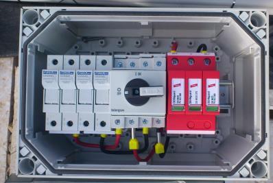
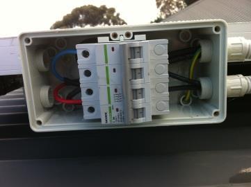
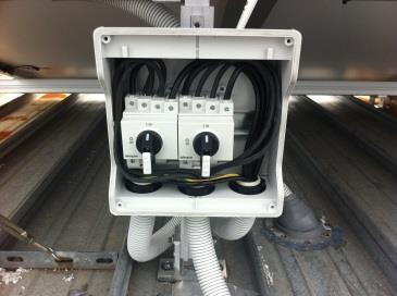
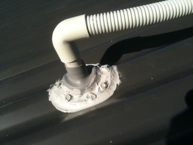
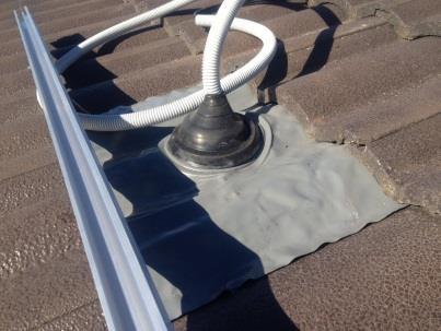
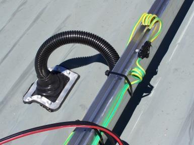


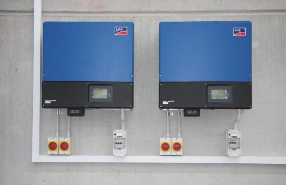

21 P-07 Rooftop Isolator & string Fuses if required. P-08 Roof Penetration (Main Cable entry point from array) P-09 DC Cable identification, mechanical protection & reticulation P-10 Under-Module cabling / cables secured from damage. On the Ground P-11 Inverter & Isolators installed (Broad View)


22 P-12 Close up- DC isolator Internal View (showing wiring) P-13 Main Switchboard / Meter Panel & Upstream Switchboard Labeling (1, 2 or more pictures to cover all below) P-14 Close up of batteries (showing link connections)


23 P-15 Close up of battery enclosure (showing ventilation) BATTERY ENCLOSURE EXAMPLES ONLY Battery Room Battery/Equipment Room Note: 1. This is a dedicated Battery and/or Battery/Equipment room that is secured to prevent unauthorized entry 2. The equipment room is ventilated to the outside as per AS4086.2
24 Note: The battery enclosure is ventilated to the outside as per AS4086.2


")
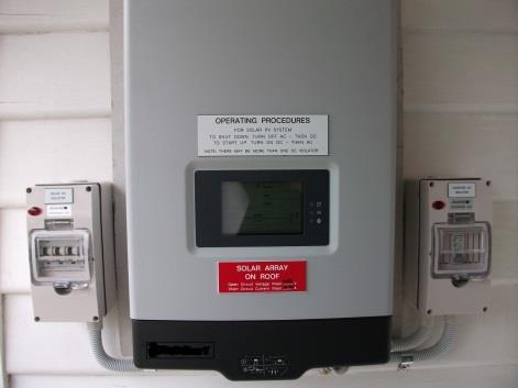
25 Examples of required labels L On switchboard to which inverter is directly connected L is permanently fixed at the main switch L is permanently fixed at the solar main switch L If the solar system is connected to a distribution board then the following sign is located on main switchboard and all intermediate distribution boards L Where the inverter is not adjacent to the main switchboard, location information is provided L Is permanently fixed on array junction boxes (black on yellow) L Fire emergency information is permanently fixed to the main switchboard and/or meter box (if not installed together) L PV DC isolation is clearly identified


26 L Is placed adjacent to the inverter when multiple isolation/disconnection devices are used that are not ganged together L Exterior surface of wiring enclosures labelled SOLAR DC SOLAR DC L-011 Installation specific Shutdown Procedure. L-011a Site plan layout Refer to AS Section 2.3, 2.4 & 2.5 Example shown L-011 & L-011a L-012 Electrolyte Burns & Danger Risk of Battery Explosion. L-012a - Example Danger risk of battery explosion & Electrolyte Burns labeling placed externally on the battery enclosure or room Danger risk of battery explosion placed externally on the battery enclosure or room L-012b - Example Electrolyte Burns labeling placed externally on the battery enclosure or room L Any other signage that may be required by local distributer. NO ENTRY AUTHORISED PERSONNEL ONLY This label should be placed externally on the battery enclosure or room


27 L-014 WARNING Uninterruptible Power Supply System L-015 Main Battery Isolator This label should be located on the main switchboard and all intermediate distribution boards This label should be placed on the Fuse Switch or DC Circuit Breaker. L-016 Earth Stake with Label L Required In Victoria on MSB This label should be located on the Earth Stake - WARNING Main Electrical Earthing Conductor Do Not Disconnect Warning, This premise contains. (Required In Victoria) Supporting Documentation & Helpful Links: Accreditation Installer Resources Bureau of Meteorology - Relevant Standards (NOTE: some aspects of these standards are relevant to grid-connected PV systems) - AS/NZS 3000 Wiring rules - AS/NZS 3008 Selection of cables - AS/NZS 1768 Lightning protection - AS/NZS Wind loads - AS 3595 Energy management programs - AS/NZS 5033: AS/NZS Stand-alone power - AS/NZS Grid connection Safety and Installation energy systems via inverters - AS/NZS Stand-alone power - AS/NZS Stand-alone power System Design Installation and Maintenance - AS Secondary Batteries for use with Stand-alone Power Systems
28 THE FINAL CHECKLIST! HAVE YOU INCLUDED THE FOLLOWING? 1 The Application form 2 Copy of your Electrical License 3 Copy of your Current Public Liability Insurance 4 Installer ID Photo 5 Testing & Commissioning Sheet 6 Wiring Diagram with equipment details 7 System Performance Estimate (Best/Worst Month) 8 Engineers Certificate for mounting frames 9 Details of your wind region & rail foot spacing 10 System Load Design 11 Installation Photographs Failure to supply any of the above will result in long delays processing your case as we await the missing information. Note: Clean Energy Council have a 5MB size limit on incoming s so you may need to re-size pictures if you are ing them.
KAUAI ISLAND UTILITY COOPERATIVE KIUC Tariff No. 1 RULE NO. 17 NET ENERGY METERING
 Third Revised Sheet 55a Cancels Second Revised Sheet 55a A. ELIGIBLE CUSTOMER-GENERATOR RULE NO. 17 NET ENERGY METERING Net energy metering is available to eligible customer-generators, defined as, permanent
40kW (and under) Solar/Inverter Installations Generation Interconnection Application to Minnesota Power
 Solar/Inverter Installations Generation Interconnection Application to Minnesota Power") 40kW (and under) Solar/Inverter Installations Generation Interconnection Application to Minnesota Power WHO SHOULD FILE THIS APPLICATION: Anyone expressing interest to install generation which will interconnect
40kW (and under) Solar/Inverter Installations Generation Interconnection Application to Minnesota Power WHO SHOULD FILE THIS APPLICATION: Anyone expressing interest to install generation which will interconnect
Connecting your home or small business generation
 Connecting your home or small business generation For connections 10kW or less March 2018 2 Contents Introduction to small distributed generation systems 3 Congestion management and safety 6 Application
Solar PV General Introduction Guide for Electricians
 Solar PV General Introduction Guide for Electricians Important Note: This guide was written to provide a broad guidance for electricians that would like to expand their product knowledge and skills for
Micro Embedded generation
 Application form Micro Embedded generation Application for new connection and supply of an embedded generator (incl. solar, wind & micro-hydro) Please print and complete relevant sections of this form
Rider : NET METERING SERVICE AND ELECTRICAL SYSTEM INTEGRATION
 SAMPLE ORDINANCE 3/5/2012 Rider : NET METERING SERVICE AND ELECTRICAL SYSTEM INTEGRATION Section 1: Applicable Service Territory Net metering and electrical system interconnection is available on a first-come,
Columbia Water & Light Interconnection & Net Metering Agreement Electrical Facility
 Processed Date Columbia Water & Light Interconnection & Net Metering Agreement Electrical Facility Customer s Printed Name Installation Street Address Account Number Please note: Columbia Water & Light
Enquiry Form for Micro and Small Generators 5MW and Less
 Enquiry form Enquiry Form for Micro and Small Generators 5MW and Less Connect an embedded generator (incl. solar, wind & micro-hydro) to the TasNetworks Distribution Network Please print and complete relevant
Renewable Energy System - Electricity System Connection Application Form
 Renewable Energy System - Electricity System Connection Application Form If you would like assistance completing this form, please email renewables@horizonpower.com.au This is an application to connect
Municipality Generator Interconnection Application Single Meter Application Part I
 Municipality Generator Interconnection Application Single Meter Application Part I New Application Revised Application A single customer interconnecting to a single meter at a single premise makes a new
RULE 21 GENERATING FACILITY INTERCONNECTION APPLICATION SMUD s Distribution System - (SMUD FORM 2655)
") - (SMUD FORM 2655) A. Applicability: This Generating Facility Interconnection Application (Application) shall be used to request the interconnection of a Generating Facility to Sacramento Municipal Utility
- (SMUD FORM 2655) A. Applicability: This Generating Facility Interconnection Application (Application) shall be used to request the interconnection of a Generating Facility to Sacramento Municipal Utility
Information Packet Kissimmee Utility Authority Customer-Owned Renewable Generation Interconnection And Net Metering Program
 Information Packet Kissimmee Utility Authority Customer-Owned Renewable Generation Interconnection And Net Metering Program As part of our commitment to support renewable energy, Kissimmee Utility Authority
Solar Power Installation Application
 Solar Power Installation Application This Form must be filled out and submitted to Logan City Light and Power Department and given authorization to proceed PRIOR to installing a solar system. Also, please
AS/NZS :2016. Grid connection of energy systems via inverters AS/NZS :2016. Part 1: Installation requirements
 AS/NZS 4777.1:2016 Australian/New Zealand Standard Grid connection of energy systems via inverters Part 1: Installation requirements AS/NZS 4777.1:2016 AS/NZS 4777.1:2016 This joint Australian/New Zealand
SSEFITAPP 2012_08_07 v2.1. FeeD-In TArIFF APPlICATIon ForM
 FeeD-In TArI APPlICATIon ForM If you wish to register for the Feed-in Tariff (FIT) Scheme with SSE Energy Supply Ltd as your FIT provider, please complete the following application form. Please read and
Louisville Gas and Electric Company
 P.S.C. Electric No. 11, Original Sheet No. 57 APPLICABLE In all territory served. AVAILABILITY OF SERVICE Available to any customer-generator who owns and operates a generating facility located on Customer
Document Requirements for Engineering Review- PV Systems v1.1 12/6/2018
 Document Requirements for Engineering Review- PV Systems v1.1 12/6/2018 Outlined below are the engineering documents and their associated minimum detail requirements for a Distributed Energy Resource (DER)
New Ulm Public Utilities. Interconnection Process and Requirements For Qualifying Facilities (0-40 kw) New Ulm Public Utilities
 New Ulm Public Utilities") New Ulm Public Utilities Interconnection Process and Requirements For Qualifying Facilities (0-40 kw) New Ulm Public Utilities INDEX Document Review and History... 2 Definitions... 3 Overview... 3 Application
New Ulm Public Utilities Interconnection Process and Requirements For Qualifying Facilities (0-40 kw) New Ulm Public Utilities INDEX Document Review and History... 2 Definitions... 3 Overview... 3 Application
Renewable Energy Interconnection Manual for Small Size Systems ( 10kW in NM 20kW in TX) Renewables and Emergent Technologies Group
 Renewables and Emergent Technologies Group") Renewable Energy Interconnection Manual for Small Size Systems ( 10kW in NM 20kW in TX) Renewables and Emergent Technologies Group Table of Contents 1. Introduction... 1 2. Purpose... 1 3. Customer Eligibility...
Renewable Energy Interconnection Manual for Small Size Systems ( 10kW in NM 20kW in TX) Renewables and Emergent Technologies Group Table of Contents 1. Introduction... 1 2. Purpose... 1 3. Customer Eligibility...
Todae Solar s 1.22 MWp Rooftop Solar Photovoltaic Installation for Stockland Shellharbour, NSW.
 Todae Solar s 1.22 MWp Rooftop Solar Photovoltaic Installation for Stockland Shellharbour, NSW. The Project Highlights Design Requirements and Technical Details Innovation and Best Practice The Project
14 October 09 Vas Kandiah AOQ SSMBB
 14 October 09 Vas Kandiah AOQ SSMBB Content Solar Farm Examples Design concepts Provisioning Process Standards Issues Use of DMAIC Questions Ground Mount Solar Farm (Spain) http://www.kyocerasolar.com/about/installations.html
RENEWABLE ENERGY PROGRAM Step 1, Section 1 ENROLLMENT FORM FOR LEASED RESIDENTIAL AND SMALL COMMERCIAL PHOTOVOLTAIC AND WIND TURBINE SYSTEMS
 RENEWABLE ENERGY PROGRAM Step 1, Section 1 ENROLLMENT FORM FOR LEASED RESIDENTIAL AND SMALL COMMERCIAL PHOTOVOLTAIC AND WIND TURBINE SYSTEMS For residential and commercial systems, the combined generation
BESS Labelling Location Sign Source Notes
 BESS Labelling Location Sign Source Notes Cl 6.2(a) Cl 6.2(b) Adjacent to main switch of IES Cl 6.2(c) Adjacent to main switch of grid supply Cl 6.2(d) Adjacent to isolator for the normal supply to the
Renewable Energy Interconnection Manual for Small Size Systems ( 10kW in NM 20kW in TX) Renewables and Emergent Technologies Group
 Renewables and Emergent Technologies Group") Renewable Energy Interconnection Manual for Small Size Systems ( 10kW in NM 20kW in TX) Renewables and Emergent Technologies Group Table of Contents 1. Introduction... 1 2. Purpose... 1 3. Customer Eligibility...
Renewable Energy Interconnection Manual for Small Size Systems ( 10kW in NM 20kW in TX) Renewables and Emergent Technologies Group Table of Contents 1. Introduction... 1 2. Purpose... 1 3. Customer Eligibility...
Consumer Guidelines for Electric Power Generator Installation and Interconnection
 Consumer Guidelines for Electric Power Generator Installation and Interconnection Habersham EMC seeks to provide its members and patrons with the best electric service possible, and at the lowest cost
INSTALLATION MANUAL CRYSTALLINE SOLAR MODULES
 Sapphire Solar Pty Ltd Phone: 1300 308 751 Email: customerservice@sapphire-solar.com 4/320 Lorimer Street, Port Melbourne VIC Australia 3207 TABLE OF CONTENTS 1. ABOUT THIS MANUAL... 3 2. DISCLAIMER OF
Net +Plus Connection Code
 Net +Plus Connection Code LANKA ELECTRICITY COMPANY (PRIVATE) LIMITED 1.0 BACKGROUND The existing Net Metering Concept launched in the year 2010 noticed an exponential growth in the recent year and at
City of Banning Electric Utility - Residential Self Generating Facility Program (Photovoltaic Systems <48kW)
") City of Banning Electric Utility - Residential Self Generating Facility Program (Photovoltaic Systems
City of Banning Electric Utility - Residential Self Generating Facility Program (Photovoltaic Systems
INTERCONNECTION RULES AND REGULATIONS FOR NET ENERGY METERING SYTEMS
 INTERCONNECTION RULES AND REGULATIONS FOR NET ENERGY METERING SYTEMS TABLE OF CONTENTS Purpose and Scope...2 Authority...2 Applicability... 2 Intent.. 2 Maximum Connected Generation Allowed. 2 Definitions.
Northeastern Rural Electric Membership Corporation Columbia City, Indiana
 Page 1 of 5 SCHEDULE ADG - 1 AGGREGATED DISTRIBUTED GENERATION SERVICE I. AVAILABILITY This Aggregated Distributed Generation Schedule is available to any member in good standing of Northeastern REMC (Northeastern),
Solar*Rewards Frequently asked questions system size and customer usage
 Solar*Rewards 1. Will a PV system work with my home? 2. Am I eligible to participate in the Solar*Rewards program? 3. What size system should I get? 4. Can a customer at a service location apply for the
Technical Standard - TS 129. Small Inverter Energy Systems (IES) - Capacity not exceeding 30kW. SA Power Networks. Published: November 2017
 - Capacity not exceeding 30kW. SA Power Networks. Published: November 2017") TS 130: Inverter Energy Systems (IES) - capacity up to or equal to 200 kw Technical Standard - TS 129 Small Inverter Energy Systems (IES) - Capacity not exceeding 30kW Published: November 2017 SA Power
TS 130: Inverter Energy Systems (IES) - capacity up to or equal to 200 kw Technical Standard - TS 129 Small Inverter Energy Systems (IES) - Capacity not exceeding 30kW Published: November 2017 SA Power
INTERCONNECTION STANDARDS FOR CUSTOMER-OWNED GENERATING FACILITIES 25 kw OR LESS PUBLIC UTILITY DISTRICT NO. 1 OF CHELAN COUNTY
 INTERCONNECTION STANDARDS FOR CUSTOMER-OWNED GENERATING FACILITIES 25 kw OR LESS PUBLIC UTILITY DISTRICT NO. 1 OF CHELAN COUNTY Table of Contents Chapter 1. Purpose and scope. Pg 3 Chapter 2. Application
My Reserve 500 Install Guide
 My Reserve 500 Install Guide System Overview Diagram Warnings Disclaimer of Liability and Warranty: This guide does not replace the Owner s Guide and Installation Instructions supplied with the components.
SOUTH HADLEY ELECTRIC LIGHT DEPARTMENT Net Metering Policy As Amended 03/23/16 By the South Hadley Municipal Light Board
 SOUTH HADLEY ELECTRIC LIGHT DEPARTMENT Net Metering Policy As Amended 03/23/16 By the South Hadley Municipal Light Board Policy Description: In an effort to ensure fair treatment of all of its customers,
To complete the process for a net metering interconnection, please follow the steps below:
 We appreciate your interest in Rocky Mountain Power s net metering program. Before purchasing any net metering equipment, we recommend you review the requirements for interconnecting a net metering system
2016 Photovoltaic Solar System Plan Review List
 Building Division 555 Santa Clara Street Vallejo CA 94590 707.648.4374 2016 Photovoltaic Solar System Plan Review List GENERAL PROJECT INFORMATION PLAN CHECK NO DATE JOB ADDRESS CITY ZIP REVIEWED BY PHONE
Marina Bay Sands Guidelines for Electrical and Wiring Service
 Marina Bay Sands Guidelines for Electrical and Wiring Service 1) The supply of electrical mains in the licensed area of the event is an exclusive service offered by Marina Bay Sands (MBS). In the event
APPLICATION Net Energy Metering Interconnection For Solar And/Or Wind Electric Generating Facilities Of 30 Kilowatts Or Less
 IMPORTANT NOTES: Customers may not operate their Generating Facility while interconnected to the PG&E system until they receive written permission from PG&E. For a non-exporting Generating Facility, RES-BCT
To complete the process for a net metering interconnection, please follow the steps below:
 We appreciate your interest in Pacific Power s net metering program. Before purchasing any net metering equipment, we recommend you review the requirements for interconnecting a net metering system to
ENGINEERING SPECIFICATION
 December 206 ENGINEERING SPECIFICATION No. of 6 DATE: 2-9-6 CATEGORY SUBJECT TABLE OF CONTENTS. Overview... 2 2. General Requirements for Service... 3 3. Definitions... 3 4. Abbreviations... 5 5. References
Mike Holt s Illustrated Guide to SOLAR PV SYSTEMS
 Mike Holt s Illustrated Guide to Directory, Identification, Label, Marking, Plaque, and Sign Requirements for SOLAR PV SYSTEMS Extracted From Mike Holt s Illustrated Guide to Understanding NEC Requirements
672W Off Grid Residential Package
 672W Off Grid Residential Package List Price:$9,578.71 Our Price: $8,523.43 Save: $1,055.28 Our Code: KITOFFGRID-A This item is a package made up of the following components. Please call to speak to a
# 1, Bowes Place, Phillip, ACT 2606, Australia. Phone:
 ABN: 75 61 61 71 147 HYBRID SOLAR POWER # 1, Bowes Place, Phillip, ACT 2606, Australia. Phone: 1300 131 989. Email: sales@hybridpowersolar.com.au www.hybridpowersolar.com INDEX WELCOME NOTE Page 3 HOW
Umatilla Electric Cooperative Net Metering Rules
 Umatilla Electric Cooperative Net Metering Rules Version: July 2017 Umatilla Electric Cooperative NET METERING RULES Rule 0005 Scope and Applicability of Net Metering Facility Rules (1) Rule 0010 through
Off Grid Cabin Special Pkg 1-170W PV
 Off Grid Cabin Special Pkg 1-170W PV List Price: $2,693.75 Our Price: $2,346.90 Save: $346.85 Model: Solar Cabin DC Package 1 Our Code: KITCABIN1 This item is a package made up of the following components.
REVISED 8/1/2018 SOLAR PHOTOVOLTAIC DISTRIBUTED GENERATION CUSTOMER GUIDELINES, APPLICATION & WGC INTERCONNECTION AGREEMENT
 REVISED 8/1/2018 SOLAR PHOTOVOLTAIC DISTRIBUTED GENERATION CUSTOMER GUIDELINES, APPLICATION & WGC INTERCONNECTION AGREEMENT INTRODUCTION Lathrop Irrigation District has created a policy to allow safe connection
London Hydro Connection Checklist
 London Hydro Connection Checklist Applicants should be aware not to incur expenses prior to London Hydro approving the connection of the facility to the grid. Payment of Connection Fee: $1000 plus HST
SUPPLEMENTAL CORRECTION SHEET FOR SOLAR PHOTOVOLTAIC SYSTEMS - ELECTRICAL
 SUPPLEMENTAL CORRECTION SHEET FOR SOLAR PHOTOVOLTAIC SYSTEMS - ELECTRICAL This is intended to provide uniform application of the codes by the plan check staff and to help the public apply the codes correctly.
LIGHTNING PROTECTION UNIT (LPU)
") LIGHTNING PROTECTION UNIT (LPU) Photovoltaic Lightning Protection Device Installation and Operation Manual SPECIALTY CONCEPTS, INC. 8954 Mason Ave. Chatsworth, CA 91311 USA MODELS COVERED: LPU-50, LPU-150,
LIGHTNING PROTECTION UNIT (LPU) Photovoltaic Lightning Protection Device Installation and Operation Manual SPECIALTY CONCEPTS, INC. 8954 Mason Ave. Chatsworth, CA 91311 USA MODELS COVERED: LPU-50, LPU-150,
TROJAN BATTERY COMPANY Renewable Energy Warranty Claim Form
 Date: CUSTOMER INFORMATION Name: Address: City: Country: Email: Company: State: Phone: Fax: TO RECEIVE WARRANTY SUPPORT FOR TROJAN BATTERY PRODUCTS USED IN RENEWABLE ENERGY APPLICATIONS, THE FOLLOWING
- Solar PV systems and integration - GIZ - All rights reserved
 - Solar PV systems and integration - 1 Content Part 2 1. Single line diagrams of Solar PV systems 2. Integration of Solar PV components 3. Understanding batteries Realisation 4. Different Solar PV systems
Net Metering Service. Customer Information Package
 Net Metering Service Customer Information Package March 20, 2017 Net Metering - The means of measuring the difference between the electricity supplied by an electric utility and the electricity generated
It is strongly recommended that you do not ship your vehicle until after you receive your Import Approval
 Application for Approval to Import a Vehicle It is strongly recommended that you do not ship your vehicle until after you receive your Import Approval Carefully read Importing Vehicles to Australia by
Application for Operation of & Net Metering for Member-Owned Generation Name: Mailing Address: City: County: State: Zip Code: _
 Application for Operation of & Net Metering for Member-Owned Generation -------------- OWNER/APPLICANT INFORMATION Name: Mailing Address: City: County: State: Zip Code: _ Phone Number: Email Address:.Representative:
Micro3 Grid Tied Residential Package
 Micro3 Grid Tied Residential Package List Price: $6,616.99 Our Price: $5,906.60 Save: $710.39 Model: Micro3 Grid-Tied Package Brand: Greener Energy Our Code: KITONGRIM3 This item is a package made up of
Bulletin Wiring methods for Solar Photovoltaic Systems Rules, 2-034, , and , Tables 11 and 19
 Bulletin 50-4-4 Wiring methods for Solar Photovoltaic Systems Rules, 2-034, 50-014, 50-018 and 50-020, Tables 11 and 19 Scope (1) Introduction (2) New cable types RPV & RPVU (3) Wiring methods within photovoltaic
The Green Meter Adapter (GMA) program will become effective on January 15, Customers may start applying for a GMA on January 15, 2018.
 program will become effective on January 15, Customers may start applying for a GMA on January 15, 2018.") SUMMARY This bulletin introduces a new PG&E program that allows the installation of an electric meter socket adapter that will accept a wired connection directly from a residential customer s Photo Voltaic
SUMMARY This bulletin introduces a new PG&E program that allows the installation of an electric meter socket adapter that will accept a wired connection directly from a residential customer s Photo Voltaic
SOLAR PHOTOVOLTAIC DISTRIBUTED GENERATION CUSTOMER GUIDELINES, APPLICATION & INTERCONNECTION AGREEMENT
 SOLAR PHOTOVOLTAIC DISTRIBUTED GENERATION CUSTOMER GUIDELINES, APPLICATION & INTERCONNECTION AGREEMENT INTERCONNECTION AGREEMENT FOR SOLAR PHOTOVOLTAIC DISTRIBUTED GENERATION THIS AGREEMENT MUST ACCOMPANY
APPLICATION Net Energy Metering (NEM2) Interconnection For Solar And/Or Wind Electric Generating Facilities Of 30 Kilowatts Or Less
 Interconnection For Solar And/Or Wind Electric Generating Facilities Of 30 Kilowatts Or Less") IMPORTANT NOTES: Customers may not operate their Generating Facility while interconnected to the PG&E system until they receive written permission from PG&E. For a non-exporting Generating Facility, RES-BCT
IMPORTANT NOTES: Customers may not operate their Generating Facility while interconnected to the PG&E system until they receive written permission from PG&E. For a non-exporting Generating Facility, RES-BCT
Duke Energy Carolinas North Carolina Interconnection Request Checklist
 Duke Energy Carolinas North Carolina Interconnection Request Checklist The North Carolina Utilities Commission issued North Carolina Interconnection Procedures, Forms, And Agreements For State-Jurisdictional
Off Grid Residential Package 1.0KW
 Off Grid Residential Package 1.0KW List Price: $12,876.63 Our Price: $11,545.59 Save: $1,331.04 (10%) Model: Off-Grid Res Pkg 1kW Our Code: KITOFFGRID-B This item is a package made up of the following
THE EMPIRE DISTRICT ELECTRIC COMPANY P.S.C. Mo. No. 5 Sec. 4 1st Revised Sheet No. 23
 P.S.C. Mo. No. 5 Sec. 4 1st Revised Sheet No. 23 Canceling P.S.C. Mo. No. 5 Sec. 4 Original Sheet No. 23 PURPOSE: The purpose of this Rider SR is to implement the solar rebate established through 393.1030
FAQ s. Designing metering switchboards as per Victorian service installation rules
 FAQ s Designing metering switchboards as per Victorian service installation rules Designing metering switchboards as per Victorian service installation rules Q: Who develops the Victorian service installation
Key Points on Design of Commercial Scale Distributed Photovoltaic System Produced by: Rodd Zhang and Carl Patrick. Presenter: Rodd Zhang
 Key Points on Design of Commercial Scale Distributed Photovoltaic System Produced by: Rodd Zhang and Carl Patrick Presenter: Rodd Zhang Disclaimer This Presentation will aim to provide recommendations
ALZ Electrical Solar Consumer Guide
 ALZ Electrical Solar Consumer Guide ALZ Electrical Unit 6/3 Southern Cross Circuit, Urangan QLD 4655 T: (07) 4124 9552 E: admin@alzelectrical.net W: www.alzelectrical.net Why go solar? Solar power systems
Solar Power Owner s Manual
 Solar Power Owner s Manual Domestic Photovoltaic Systems Introduction Congratulations on the purchase of your solar electricity system. Not only are you protecting yourself from current and future price
JEA Distributed Generation Policy Effective April 1, 2018
 Summary This JEA Distributed Generation Policy is intended to facilitate generation from customer-owned renewable and non-renewable energy generation systems interconnecting to the JEA electric grid. The
Origin Solar Presentation
 Origin Solar Presentation Presentation to: Body Corporate Seminar Location: Colmslie Hotel Morningside Date : 08-03-2011 Origin Solar Presentation Body Corporate Seminar Page 2 Figures based on Origin's
WOLFEBORO MUNICIPAL ELECTRIC DEPARTMENT NET METERING PILOT PROGRAM. Customer-Owned Renewable Energy Generation Resources (25 Kilowatts or Less)
") WOLFEBORO MUNICIPAL ELECTRIC DEPARTMENT NET METERING PILOT PROGRAM Customer-Owned Renewable Energy Generation Resources (25 Kilowatts or Less) Issued and Effective: April 3, 2008 Agreement Between And
WOLFEBORO MUNICIPAL ELECTRIC DEPARTMENT NET METERING PILOT PROGRAM Customer-Owned Renewable Energy Generation Resources (25 Kilowatts or Less) Issued and Effective: April 3, 2008 Agreement Between And
CP-250E-60/72-208/240-MC4 Microinverter with Modular Trunk Cable
 CP-250E-60/72-208/240-MC4 Microinverter with Modular Trunk Cable Chilicon Power Aug 2016 1 CONTENTS CP-250E Microinverter System... 3 The CP-100 Cortex Gateway... 3 Important Safety Information... 4 Inverter
New Jersey Motor Vehicle Commission
 P.O. Box 170 Trenton, New Jersey 08666-0170 (609) 292-6500 ext. 5014 Chris Christie Governor Kim Guadagno Lt. Governor Raymond P. Martinez Chairman and Chief Administrator Announcement All Initial Business
Requirement Definition/Terms of Reference Satellite Beach City Hall - Solar Array Installation
 Requirement Definition/Terms of Reference Satellite Beach City Hall - Solar Array Installation RFP No. 16-17-07 Solar Energy for City Hall, Page 1 of 10 Contents Site Description... 3 Panels (provide panel
Photovoltaic Solar Plan Review
 PAIGE B. VAUGHAN, CBO Director of Building and Safety Phone (310) 605-5509 Fax Line (310) 605-5598 E-mail:lbutler@comptoncity.org Building & Safety Department Photovoltaic Solar Plan Review Plan Check
December 13, This document was filed with the Board of Public Utilities on December 13, It is awaiting final approval by BPU staff.
 JERSEY CENTRAL POWER & LIGHT UNIFORM TECHNICAL AND PROCEDURAL INTERCONNECTION REQUIREMENTS FOR NET METERING FACILITIES FOR INVERTER BASED WIND AND PHOTOVOLTAIC SYSTEMS OF 100 kw OR SMALLER for Atlantic
Show Name: Anaheim Home & Garden Show 2018 ELECTRICAL
 Show Name: Anaheim Home & Garden Show 2018 Show Location: Anaheim Convention Center Show Dates: August 17-19, 2018 INFORMATION ELECTRICAL SAVE MONEY READ THIS FIRST Complete the attached form to ensure
TERMS AND CONDITIONS
 XXV. NET METERING A. Applicability and Availability 1. The terms Net Metering Service, Demand Charge-based Time-of- Use Tariff, Net Metering Customer, Customer, Time-of-Use Customer, Time-of-Use Tier,
Non-Residential Solar Energy Photovoltaic (PV) Packet
 Packet") Development Services Department Building Inspection Division 311 Vernon Street Roseville, California 95678-2649 (916) 774-5332 Fax (916) 774-5394 Non-Residential Solar Energy Photovoltaic (PV) Packet Permit
Development Services Department Building Inspection Division 311 Vernon Street Roseville, California 95678-2649 (916) 774-5332 Fax (916) 774-5394 Non-Residential Solar Energy Photovoltaic (PV) Packet Permit
Oncor Application for Interconnection of Distributed Generation
 Oncor Application for Interconnection of Distributed Generation Certified Systems (12/7/2017) What is a certified system? A certified system is one that meets the requirements of UL-1741 Utility Interactive
Northeastern Rural Electric Membership Corporation Schedule DG-2 Columbia City, Indiana Page 1 of 5
 Columbia City, Indiana Page 1 of 5 SCHEDULE DG-2 LARGE POWER DISTRIBUTED GENERATION I. AVAILABILITY This Distributed Generation Rate is available to any member in good standing of Northeastern REMC (Northeastern)
Note: it is a criminal offence to give false information in this application.
 Note: it is a criminal offence to give false information in this application. Section 1 - Your contact details (Please read Guidance Note 1) 1a) Please give full details of the person that can be contacted
HydroGenerations PROGRAM HANDBOOK
 HydroGenerations PROGRAM HANDBOOK TABLE OF CONTENTS Please ensure you are reading the most recent version of this handbook by visiting the NV Energy website, www.nvenergy.com/hydro. Contents HydroGenerations
Document Requirements for Engineering Review PV Systems v1.0 6/9/2017
 Document Requirements for Engineering Review PV Systems v1.0 6/9/2017 Outlined below are the documents and associated minimum details required for Engineering Review of Distributed Energy Resources Interconnection
RET PROCESS FOR OWNERS OF SMALL GENERATION UNITS (SGUs)
") SGU Owners Guide RET PROCESS FOR OWNERS OF SMALL GENERATION UNITS (SGUs) small-scale solar photovoltaic panels, wind and hydro electricity units In this fact sheet: Options for gaining financial benefits
SGU Owners Guide RET PROCESS FOR OWNERS OF SMALL GENERATION UNITS (SGUs) small-scale solar photovoltaic panels, wind and hydro electricity units In this fact sheet: Options for gaining financial benefits
Capabilities Brochure
 Eaton Corporation - Electrical Division Capabilities Brochure Australia and New Zealand An Introduction to Eaton Corporation Eaton Corporation is a diversified power management company with 2010 global
Guidelines for Inverter-Based Micro-Generating Facility (10 kw and Smaller)
") Guidelines for Inverter-Based Micro-Generating Facility (10 kw and Smaller) Cover: Photos courtesy of Balance Solutions for Today Inc OVERVIEW Today many home, farm and small business owners are considering
Guidelines for Inverter-Based Micro-Generating Facility (10 kw and Smaller) Cover: Photos courtesy of Balance Solutions for Today Inc OVERVIEW Today many home, farm and small business owners are considering
IMPORTANT INFORMATION ABOUT THIS APPLICATION
 MotorSport NZ Inc 69 Hutt Road, Thorndon PO Box 3793, Wellington 6015 Ph: 04 815 8015 Fax: 04 472 9011 Web: motorsport.org.nz SAFETY CAGE / ROLLBAR HOMOLOGATION APPLICATION Technical Form T002 IMPORTANT
APPLICATION FOR INSTALLATION OF SMALL SCALE EMBEDDED ELECTRICITY GENERATION
 APPLICATION FOR INSTALLATION OF SMALL SCALE EMBEDDED ELECTRICITY GENERATION Work Order No: File Reference: 16/2/1 This application form for the connection of small scale embedded generation is for small
Noble County Rural Electric Membership Corporation
 Albion, Indiana Page 1 of 5 SCHEDULE NB-1 RESIDENTIAL NET BILLING I. AVAILABILITY This Net Billing Rate is available to any residential member in good standing of Noble REMC (Noble) who owns and operates
Solar PV Standard Electrical Plan
 *** Provide this document to the inspector along with ALL system installation instructions *** Project Address: Permit Number: SCOPE: Standard plan for installation of solar PV systems utilizing 2 wire
Inspector Training Workshops Module One Photovoltaic Labeling based on 2008 NEC
 Inspector Training Workshops Module One Photovoltaic Labeling based on 2008 NEC NJCE Market Manager HW Construction Department Wayne, NJ Robert A. Menist Contents Site inspections with attention on Labeling
Connecting your business diesel generation
 Connecting your business diesel generation March 2018 For connections more than 10kW 2 Contents Introduction to large distributed generation systems 3 Congestion management and safety 6 Application form
NCC Leisure Battery Verification Scheme. Leisure Accommodation Vehicles
 The UK trade body for the caravan, motorhome, caravan holiday and park home industry. NCC Leisure Battery Verification Scheme Leisure Accommodation Vehicles Page 1 of 11 1 Scope The NCC Battery Verification
Model Standing Offer for Micro Embedded Generator Basic Connection Services
 Model Standing Offer for Micro Embedded Generator Basic Connection Services MICRO EMBEDDED GENERATORS BASIC CONNECTION SERVICES NEW CONNECTION WITH MICRO EMBEDDED GENERATOR EXISTING CONNECTION WITH NEW
Australian Standard. Stand-alone power systems. Part 1: Safety requirements AS
 AS 4509.1 1999 Australian Standard Stand-alone power systems Part 1: Safety requirements This Australian Standard was prepared by Committee EL/42, Renewable Energy Power Supply Systems and Equipment. It
MARLBOROUGH LINES DISTRIBUTED GENERATION INFORMATION PACK
 MARLBOROUGH LINES DISTRIBUTED GENERATION INFORMATION PACK For generators rated below 10kVA Issue 7 - April 2015 Introduction to distributed generation Distributed generators, also known as embedded generators,
Distributed Generation Interconnection Policy
 Distributed Generation Interconnection Policy 1 Introduction Carroll Electric Membership Corporation Distributed Generation Interconnection Policy Carroll Electric Membership Corporation (herein after
Code Compliance. Perspectives on PV. Back to the Grid, Designing PV Systems for
 Perspectives on PV A series of articles on photovoltaic (PV) power systems and the National Electrical Code by John Wiles Back to the Grid, Designing PV Systems for Code Compliance 20 IAEI NEWS January.February
This is intended to provide uniform application of the codes by the plan check staff and to help the public apply the codes correctly.
 SUPPLEMENTAL CORRECTION SHEET FOR SOLAR PHOTOVOLTAIC SYSTEMS (ELEC) This is intended to provide uniform application of the codes by the plan check staff and to help the public apply the codes correctly.
SANTA CLARA CITY RENEWABLE NET METERING & INTERCONNECTION AGREEMENT
 SANTA CLARA CITY RENEWABLE NET METERING & INTERCONNECTION AGREEMENT This Net Metering and Interconnection Agreement ( Agreement ) is made and entered into as of this day of, 2018, by the City of Santa