SUBMITTAL COVER SHEET
|
|
|
- Kevin Pope
- 6 years ago
- Views:
Transcription
1 SUBMITTAL COVER SHEET PROJECT NAME: OWNER: ENGINEER: SUBCONTRACTOR: GENERATOR BACKUP SYSTEMS COMMUNITY CENTER, 150 NEVERS ROAD FIRE STATION #2, 750 FOSTER STREET HIGH SCHOOL, 161 NEVERS ROAD POLICE DEPT., 151 SAND HILL ROAD TOWN GARAGE, 157 BURGESS ROAD WAPPING ELEMENTARY, 91 AYERS ROAD TOWN OF SOUTH WINDSOR 1540 SULLIVAN AVENUE, SOUTH WINDSOR DIVERSIFIED TECHNOLOGY CONSULTANTS 2321 WHITNEY AVENUE, HAMDEN, CT CUSTOM ELECTRIC, INC. 52 MAIN STREET, MANCHESTER, CT SUBMITTAL DATE: SUBMITTAL NO. 1 SPEC SECTION: Engine Generators Transfer Switches DWG/DETAIL REFERENCES: INSTALLATION LOCATION: SUPPLIER Cummins Power Systems MANUFACTURER Cummins Power Generation ITEM(S) SUBMITTED: G.C./CM: REVIEWED FOR CONFORMANCE WITH CONTRACT DOCUMENTS: DATE: BY: NOTE: This cover sheet shall be attached to each copy and transmitted with each submittal.
2 Generator & ATS South Windsor Community Center
3 March 17, 2014 SUBMITTAL DRAWINGS FOR: Town of South Windsor Generator Back Up Systems Community Center 150 Nevers Road South Windsor, CT Spec Section & ENGINEER: Diversified Technology Consultants 2321 Whitney Avenue Hamden, CT Stephen Gendreau, P.E. CONTRACTOR: Custom Electric, Inc. 52 Main Street Manchester, CT Robert LaBrecque PREPARED BY: Mary Kay Peck Cummins Power Systems, LLC 914 Cromwell Avenue Rocky Hill, CT Phone Fax
4 Connecticut Branch 914 Cromwell Ave. Rocky Hill, CT Phone: (860) Fax: (860) Bill of Material One (1) new Cummins model 125DSGAB rated at 125 kw, 120/208 volt, 3 phase, 4 wire, 60 hertz, 1800 RPM, for operation on diesel fuel. Package to include our standard accessories plus the following: EPA Tier 3 Emission Certified Engine UL2200 Listing Engine starting batteries - lead acid type Battery racks and cables Battery charging alternator Battery Charger, 10A, 12VDC, shipped loose Exhaust silencer, internally mounted Stainless steel exhaust flex Engine jacket water heater Engine mounted radiator and fan with duct flange Vibration isolators Structural steel base rails 105 degree C rise alternator Alternator Heater Onan UL 508 listed PowerCommand Control Panel featuring a microprocessor based digital control system with the following: Digital display panel Cyclic cranking control, adjustable Idle mode control Self diagnostics with LED s for self test Separate control interface box Run-off-auto switch Emergency stop switch Reset switch Menu switch Voltmeter/ammeter phase selector switch
5 Connecticut Branch 914 Cromwell Ave. Rocky Hill, CT Phone: (860) Fax: (860) Panel lights with 10 minute auto switch Digital AC voltage line to line Digital AC current by phase Digital AC kilowatts Digital AC kilowatt hours Digital AC power factor Digital engine oil pressure Digital engine coolant temperature Digital engine oil temperature Digital engine RPM (tachometer) Digital DC battery voltage Digital engine starts counter Digital engine running hours Low oil pressure shutdown and pre-alarm High engine temperature shutdown and pre-alarm Low coolant level shutdown Overspeed shutdown Fail to crank shutdown Overcrank shutdown Oil pressure sender failure warning Water temperature sender failure warning Alternator overcurrent warning Low engine temperature warning Engine overload warning with load shed Low fuel level warning Low battery voltage warning High battery voltage warning Weak battery warning Four (4) customer selected shutdowns or warnings Over and under AC voltage shutdown Under frequency shutdown Analog meters, AC Output Genset status relays Generator mainline circuit breaker, 400 Amps Isochronous electronic governor Low Coolant Level Shutdown
6 Oil & Coolant Drains PMG Excitation Remote Annunciator panel, shipped loose Steel Sound Attenuated Enclosure, Level 2 (74 23 ) Double Wall, UL Listed basetank, 945 gallons, with conduit stub up area, low fuel and leak detection switches Flexible fuel lines Five year warranty Spare Filters One Year Service Contract Lube oil and antifreeze Factory & Field Test Start Up & 2 Hour Load Bank Test One (1) new Cummins Automatic Transfer Switch, type OTPC, rated 1200 amps, 3 pole, 208 volts, 3 phase, 60 Hz, NEMA 1 enclosure, including the following: Programmed Transition Transfer Adjustable undervoltage sensors with dropout time delay Start contacts Control mode status indicators Adjustable solid state time delays Neutral bar Plant exerciser with load selector switch Switch position lights Source available lights Two (2) mainshaft auxiliary contacts Digital Display Network Communications Card Five Year Warranty Note: Infrared scanning furnished by others Connecticut Branch 914 Cromwell Ave. Rocky Hill, CT Phone: (860) Fax: (860)
7 Specification sheet Diesel Generator set QSB7 series engine kw 60 Hz Description Cummins Power Generation commercial generator sets are fully integrated power generation systems providing optimum performance, reliability and versatility for stationary standby and prime power applications. Features Cummins heavy-duty engine -Rugged 4- cycle, industrial diesel delivers reliable power, low emissions and fast response to load changes. Alternator - Several alternator sizes offer selectable motor starting capability with low reactance 2/3 pitch windings, low waveform distortion with non-linear loads and fault clearing short-circuit capability. Control system - The PowerCommand 1.1 electronic control is standard equipment and provides total genset system integration including automatic remote starting/stopping, precise frequency and voltage regulation, alarm and status message display, output metering, auto-shutdown at fault detection and NFPA 110 Level 1 compliance. The optional PowerCommand 2.2 control is UL 508 Listed and provides AmpSentry protection. Cooling system - Standard integral set-mounted radiator system, designed and tested for rated ambient temperatures, simplifies facility design requirements for rejected heat. Enclosures - Optional weather protective and sound attenuated enclosures are available. NFPA - The genset accepts full rated load in a single step in accordance with NFPA 110 for Level 1 systems. Warranty and service - Backed by a comprehensive warranty and worldwide distributor network. Standby rating Prime rating Continuous rating Data sheets 60 Hz 50 Hz 60 Hz 50 Hz 60 Hz 50 Hz Model kw (kva) kw (kva) kw (kva) kw (kva) kw (kva) kw (kva) 60 Hz 50 Hz DSGAA 100 (125) 90 (113) D-3349 DSGAB 125 (156) 113 (141) D-3350 DSGAC 150 (188) 135 (169) D-3351 DSGAD 175 (219) 160 (200) D-3516 DSGAE 200 (250) 180 (225) D Cummins Power Generation Inc. S-1544m (3/13) cumminspower.com
8 Generator set specifications Governor regulation class ISO 8528 Part 1 Class G3 Voltage regulation, no load to full load ± 1% Random voltage variation ± 0.5% Frequency regulation Isochronous Random frequency variation ± 0.25% Radio frequency emissions compliance Meets requirements of most industrial and commercial applications Engine specifications Bore 107 mm (4.21 in) Stroke mm (4.88 in) Displacement 6.69 L (408 in 3 ) Configuration Cast iron, in-line, 6 cylinder Battery capacity 1100 amps minimum at ambient temperature of -18 C to 0 C (0 F to 32 F) Battery charging alternator 100 amps Starting voltage 12 volt, negative ground Fuel system Direct injection: number 2 diesel fuel, fuel filter, automatic electric fuel shutoff Fuel filter Single element, 10 micron filtration, spin-on fuel filter with water separator Air cleaner type Dry replaceable element Lube oil filter type(s) Spin-on, full flow Standard cooling system High ambient radiator Alternator specifications Design Brushless, 4 pole, drip proof, revolving field Stator 2/3 pitch Rotor Single bearing, flexible discs Insulation system Class H Standard temperature rise 150 ºC standby at 40 C ambient Exciter type Torque match (shunt) standard, PMG optional Phase rotation A (U), B (V), C (W) Alternator cooling Direct drive centrifugal blower fan AC waveform total harmonic distortion < 5% no load to full linear load, < 3% for any single harmonic Telephone influence factor (TIF) < 50 per NEMA MG Telephone harmonic factor (THF) < 3 Available voltages 60 Hz Three phase line-neutral/line-line 60 Hz Single phase line-neutral/line-line 110/ / / /230 Delta 120/ /240 Delta 110/ / / / / / / / / / /600 Note: Consult factory for other voltages. Generator set options and accessories Engine 120 V 150 W lube oil heater 120/240 V 1500 W coolant heater Fuel System 24 hour sub-base tank (dual wall) Alternator 105 C rise 125 C rise 120 V 100 W anticondensation heater PMG excitation Single phase (not available with DSGAD or DSGAE) Exhaust system Heavy duty exhaust elbow Slip on exhaust connection Generator set Battery Battery charger Enclosure: aluminum, steel, weather protective or sound attenuated Main line circuit breaker Remote annunciator panel Spring isolators 2 year prime power warranty 2 year standby power warranty 5 year basic power warranty Note: Some options may not be available on all models - consult factory for availability Cummins Power Generation Inc. S-1544m (3/13) cumminspower.com
9 Control system PowerCommand 1.1 PowerCommand control is an integrated generator set control system providing voltage regulation, engine protection, operator interface and isochronous governing (optional). Major features include: Battery monitoring and testing features and smart starting control system. Standard PCCNet interface to devices such as remote annunciator for NFPA 110 applications. Control boards potted for environmental protection. Control suitable for operation in ambient temperatures from -40 C to +70 C (-40 F to +158 F) and altitudes to 5000 meters (13,000 feet). Prototype tested; UL, CSA, and CE compliant. InPower PC-based service tool available for detailed diagnostics. Operator/display panel Manual off switch Alpha-numeric display with pushbutton access for viewing engine and alternator data and providing setup, controls and adjustments (English or international symbols) LED lamps indicating genset running, not in auto, common warning, common shutdown, manual run mode and remote start Suitable for operation in ambient temperatures from -20 C to +70 C Bargraph display (optional) AC protection Over current warning and shutdown Over and under voltage shutdown Over and under frequency shutdown Over excitation (loss of sensing) fault Field overload Engine protection Overspeed shutdown Low oil pressure warning and shutdown High coolant temperature warning and shutdown Low coolant level warning or shutdown Low coolant temperature warning High, low and weak battery voltage warning Fail to start (overcrank) shutdown Fail to crank shutdown Redundant start disconnect Cranking lockout Sensor failure indication Low fuel level warning or shutdown Fuel-in-rupture-basin warning or shutdown Alternator data Line-to-line and line-to-neutral AC volts 3-phase AC current Frequency Total kva Engine data DC voltage Lube oil pressure Coolant temperature Engine speed Other data Genset model data Start attempts, starts, running hours Fault history RS485 Modbus interface Data logging and fault simulation (requires InPower service tool) Digital governing (optional) Integrated digital electronic isochronous governor Temperature dynamic governing Digital voltage regulation Integrated digital electronic voltage regulator 2-phase line-to-line sensing Configurable torque matching Control functions Time delay start and cooldown Cycle cranking PCCNet interface (2) Configurable inputs (2) Configurable outputs Remote emergency stop Glow plug control (some models) Options Auxiliary output relays (2) 120/240 V, 100 W anti-condensation heater Remote annunciator with (3) configurable inputs and (4) configurable outputs PMG alternator excitation PowerCommand iwatch web server for remote monitoring and alarm notification (loose) Auxiliary, configurable signal inputs (8) and configurable relay outputs (8) Digital governing AC output analog meters (bargraph) - Color-coded graphical display of: - 3-phase AC voltage - 3-phase current - Frequency - kva Remote operator panel PowerCommand 2.2 control with AmpSentry protection For further detail see document S Cummins Power Generation Inc. S-1544m (3/13) cumminspower.com
10 Ratings definitions Emergency standby power (ESP): Applicable for supplying power to varying electrical load for the duration of power interruption of a reliable utility source. Emergency Standby Power (ESP) is in accordance with ISO Fuel Stop power in accordance with ISO 3046, AS 2789, DIN 6271 and BS Limited-time running power (LTP): Applicable for supplying power to a constant electrical load for limited hours. Limited Time Running Power (LTP) is in accordance with ISO Prime power (PRP): Applicable for supplying power to varying electrical load for unlimited hours. Prime Power (PRP) is in accordance with ISO Ten percent overload capability is available in accordance with ISO 3046, AS 2789, DIN 6271 and BS Base load (continuous) power (COP): Applicable for supplying power continuously to a constant electrical load for unlimited hours. Continuous Power (COP) in accordance with ISO 8528, ISO 3046, AS 2789, DIN 6271 and BS North America rd Avenue N.E. Minneapolis, MN USA Phone Fax This outline drawing is for reference only. See respective model data sheet for specific model outline drawing number. Do not use for installation design Dim A Dim B Dim C Set Weight* Set Weight* Model mm (in.) mm (in.) mm (in.) dry kg (lbs) wet kg (lbs) DSGAA 2656 (104.6) 1100 (43.3) 1549 (61) 1180 (2602) DSGAB 2656 (104.6) 1100 (43.3) 1549 (61) 1225 (2700) DSGAC 2656 (104.6) 1100 (43.3) 1549 (61) 1263 (2784) DSGAD 2656 (104.6) 1100 (43.3) 1549 (61) 1361 (3000) DSGAE 2656 (104.6) 1100 (43.3) 1549 (61) 1361 (3000) * Note: Weights represent a set with standard features. See outline drawings for weights of other configurations. Codes and standards Codes or standards compliance may not be available with all model configurations consult factory for availability. This generator set is designed in facilities certified to ISO 9001 and manufactured in facilities certified to ISO 9001 or ISO The Prototype Test Support (PTS) program verifies the performance integrity of the generator set design. Cummins Power Generation products bearing the PTS symbol meet the prototype test requirements of NFPA 110 for Level 1 systems. All low voltage models are CSA certified to product class U.S. EPA International Building Code The generator set is available Listed to UL 2200, Stationary Engine Generator Assemblies for all 60 Hz low voltage models. Engine certified to Stationary Emergency U.S. EPA New Source Performance Standards, 40 CFR 60 subpart IIII Tier 3 exhaust emission levels. U.S. applications must be applied per this EPA regulation. The generator set package is available certified for seismic application in accordance with the following International Building Code: IBC2000, IBC2003 IBC2006, IBC2009 and IBC2012. Warning: Back feed to a utility system can cause electrocution and/or property damage. Do not connect to any building s electrical system except through an approved device or after building main switch is open Cummins Power Generation Inc. All rights reserved. Cummins Power Generation and Cummins are registered trademarks of Cummins Inc. PowerCommand, AmpSentry, InPower and Our energy working for you. are trademarks of Cummins Power Generation. Other company, product, or service names may be trademarks or service marks of others. Specifications are subject to change without notice. S-1544m (3/13) cumminspower.com
11 Model: DSGAB Frequency: 60 Fuel type: Diesel KW rating: 125 standby 113 prime Emissions level: EPA NSPS Stationary Emergency Tier 3 Generator set data sheet Exhaust emission data sheet: Exhaust emission compliance sheet: Sound performance data sheet: Cooling performance data sheet: Prototype test summary data sheet: Standard set-mounted radiator cooling outline: Optional set-mounted radiator cooling outline: Optional heat exchanger cooling outline: Optional remote radiator cooling outline: EDS-1084 EPA-1118 MSP-1056 MCP-171 PTS-285 A035C611 Fuel consumption Standby Prime Continuous kw (kva) kw (kva) kw (kva) Ratings 125 (156) 113 (141) Load 1/4 1/2 3/4 Full 1/4 1/2 3/4 Full Full US gph L/hr Engine Standby Prime rating rating Engine manufacturer Cummins Engine model QSB7-G5 NR3 Configuration Cast iron, in-line, 6 cylinder Aspiration Turbocharged and air-to-air aftercooled Gross engine power output, kwm (bhp) 242 (324) 208 (279) BMEP at set rated load, kpa (psi) 1467 (213) 1331 (193) Bore, mm (in) 107 (4.21) Stroke, mm (in) 124 (4.88) Rated speed, rpm 1800 Piston speed, m/s (ft/min) 7.4 (1464) Compression ratio 17.2:1 Lube oil capacity, L (qt) 17.5 (18.5) Overspeed limit, rpm 2100 Regenerative power, kw 19 Continuous rating Fuel flow Maximum fuel flow, L/hr (US gph) 106 (28) Maximum fuel flow with C174, L/hr (US gph) Maximum fuel inlet restriction with clean filter, mm Hg (in Hg) 127 (5) Maximum return restriction, mm Hg (in Hg) 152 (6) 2011 Cummins Power Generation Inc. All rights reserved. Cummins Power Generation and Cummins are registered trademarks of Cummins Inc. Our energy working for you. is a trademark of Cummins Power Generation. Specifications are subject to change without notice. D-3350e (8/11)
12 Air Standby Prime rating rating Combustion air, m 3 /min (scfm) 14.1 (497) 13.9 (492) Maximum air cleaner restriction with clean filter, kpa (in H 2 O) 3.7 (15) Alternator cooling air, m 3 /min (cfm) 37.0 (1308) Continuous rating Exhaust Exhaust flow at set rated load, m 3 /min (cfm) 32.9 (1161) 32.1 (1133) Exhaust temperature, C ( F) (835) (821) Maximum back pressure, kpa (in H 2 O) 10 (40) Standard set-mounted radiator cooling Ambient design, C ( F) 54 (129) Fan load, kwm (HP) 9.7 (13.0) Coolant capacity (with radiator), L (US Gal) 23 (6.1) Cooling system air flow, m 3 /min (scfm) 351 (12400) Total heat rejection, MJ/min (Btu/min) 7.39 (6997) 7.05 (6677) Maximum cooling air flow static restriction, kpa (in H 2 O) 0.12 (0.5) Optional set-mounted radiator cooling Ambient design, C ( F) Fan load, kwm (HP) Coolant capacity (with radiator), L (US Gal.) Cooling system air flow, m 3 /min (scfm) Total heat rejection, MJ/min (Btu/min) Maximum cooling air flow static restriction, kpa (in. H 2 O) Optional heat exchanger cooling Set coolant capacity, L (US Gal.) Heat rejected, jacket water circuit, MJ/min (Btu/min) Heat rejected, aftercooler circuit, MJ/min (Btu/min) Heat rejected, fuel circuit, MJ/min (Btu/min) Total heat radiated to room, MJ/min (Btu/min) Maximum raw water pressure, jacket water circuit, kpa (psi) Maximum raw water pressure, aftercooler circuit, kpa (psi) Maximum raw water pressure, fuel circuit, kpa (psi) Maximum raw water flow, jacket water circuit, L/min (US Gal/min) Maximum raw water flow, aftercooler circuit, L/min (US Gal/min) Maximum raw water flow, fuel circuit, L/min (US Gal/min) Minimum raw water flow at 27 C (80 F) inlet temp, jacket water circuit, L/min (US Gal/min) Minimum raw water flow at 27 C (80 F) inlet temp, aftercooler circuit, L/min (US Gal/min) Minimum raw water flow at 27 C (80 F) inlet temp, fuel circuit, L/min (US Gal/min) Raw water delta P at min flow, jacket water circuit, kpa (psi) Raw water delta P at min flow, aftercooler circuit, kpa (psi) Raw water delta P at min flow, fuel circuit, kpa (psi) Maximum jacket water outlet temp, C ( F) Maximum aftercooler inlet temp, C ( F) Maximum aftercooler inlet temp at 25 C (77 F) ambient, C ( F) Our energy working for you Cummins Power Generation Inc. All rights reserved. Cummins Power Generation and Cummins are registered trademarks of Cummins Inc. Our energy working for you. is a trademark of Cummins Power Generation. Specifications are subject to change without notice. D-3350e (8/11)
13 Optional remote radiator cooling 1 Set coolant capacity, L (US gal) Max flow rate at max friction head, jacket water circuit, L/min (US gal/min) Max flow rate at max friction head, aftercooler circuit, L/min (US gal/min) Heat rejected, jacket water circuit, MJ/min (Btu/min) Heat rejected, aftercooler circuit, MJ/min (Btu/min) Heat rejected, fuel circuit, MJ/min (Btu/min) Total heat radiated to room, MJ/min (Btu/min) Maximum friction head, jacket water circuit, kpa (psi) Maximum friction head, aftercooler circuit, kpa (psi) Maximum static head, jacket water circuit, m (ft) Maximum static head, aftercooler circuit, m (ft) Maximum jacket water outlet temp, C (F) Maximum aftercooler inlet temp at 25 C (77 F) ambient, C (F) Maximum aftercooler inlet temp, C (F) Maximum fuel flow, L/hr (US gph) Maximum fuel return line restriction, kpa (in Hg) Standby rating Prime rating Continuous rating Weights 2 Unit dry weight kgs (lbs.) Unit wet weight kgs (lbs.) 1225 (2700) Notes: 1 For non-standard remote installations contact your local Cummins Power Generation representative. 2 Weights represent a set with standard features. See outline drawing for weights of other configurations. Derating factors Standby Prime Engine power available up to 3048 m (10,000 ft) at ambient temperature up to 40 C (104 F) and 2682 m (8800 ft) at 50 C (122 F). Consult your Cummins Power Generation distributor for temperature and ambient requirements outside these parameters. Engine power available up to 3048 m (10,000 ft) at ambient temperature up to 40 C (104 F) and 1829 m (6000 ft) at 50 C (122 F). Consult your Cummins Power Generation distributor for temperature and ambient requirements outside these parameters. Continuous Ratings definitions Emergency standby power (ESP): Limited-time running power (LTP): Prime power (PRP): Base load (continuous) power (COP): Applicable for supplying power to varying electrical load for the duration of power interruption of a reliable utility source. Emergency Standby Power (ESP) is in accordance with ISO Fuel Stop power in accordance with ISO 3046, AS 2789, DIN 6271 and BS Applicable for supplying power to a constant electrical load for limited hours. Limited Time Running Power (LTP) is in accordance with ISO Applicable for supplying power to varying electrical load for unlimited hours. Prime Power (PRP) is in accordance with ISO Ten percent overload capability is available in accordance with ISO 3046, AS 2789, DIN 6271 and BS Applicable for supplying power continuously to a constant electrical load for unlimited hours. Continuous Power (COP) is in accordance with ISO 8528, ISO 3046, AS 2789, DIN 6271 and BS Our energy working for you Cummins Power Generation Inc. All rights reserved. Cummins Power Generation and Cummins are registered trademarks of Cummins Inc. Our energy working for you. is a trademark of Cummins Power Generation. Specifications are subject to change without notice. D-3350e (8/11)
14 Alternator data Three Phase Table o C 105 o C 105 o C 105 o C 125 o C 125 o C 125 o C 125 o C 125 o C 150 o C 150 o C 150 o C Feature Code B418 B415 B268 B304 B417 B414 B267 B246 B303 B416 B413 B419 Alternator Data Sheet Number Voltage Ranges 110/ / / / / / / / / / / /600 Thru 120/ /380 Thru 240/416 Thru 139/ /416 Thru 277/480 Thru 139/ /416 Thru 277/480 Thru 120/ /380 Thru 240/416 Thru 139/ /416 Thru 277/480 Thru 139/ /416 Thru 277/ /480 Thru 120/ /380 Thru 240/416 Thru 139/ /416 Thru 277/480 Surge kw Motor Starting kva (at 90% sustained voltage) Shunt PMG Full Load Current - Amps at Standby Rating 120/ / / / / / / / Single Phase Table 105 o C 105 o C 105 o C 125 o C 125 o C 125 o C 150 o C Feature Code B418 B415 B268 B417 B414 B267 B413 Alternator Data Sheet Number Voltage Ranges 120/ / / / / / /240 2 Surge kw Motor Starting kva (at Shunt % sustained voltage) PMG Full Load Current - Amps at Standby Rating 120/ / Single phase power can be taken from a three phase generator set at up to 2/3 set rated 3-phase kw at 1.0 power factor. Also see Note 3 below. 2 The broad range alternators can supply single phase output up to 2/3 set rated 3-phase kw at 1.0 power factor. 3 The extended stack (full single phase output) and 4 lead alternators can supply single phase output up to full set rated 3-phase kw at 1.0 power factor. Formulas for calculating full load currents: Three phase output Single phase output kw x 1000 kw x Single Phase Factor x 1000 Voltage x 1.73 x 0.8 Voltage Cummins Power Generation rd Avenue N.E. Minneapolis, MN USA Telephone: Fax: Warning: Back feed to a utility system can cause electrocution and/or property damage. Do not connect to any building s electrical system except through an approved device or after building main switch is open. Our energy working for you Cummins Power Generation Inc. All rights reserved. Cummins Power Generation and Cummins are registered trademarks of Cummins Inc. Our energy working for you. is a trademark of Cummins Power Generation. Specifications are subject to change without notice. D-3350e (8/11)
15 PowerCommand 2.2 control system Control system description The PowerCommand control system is a microprocessor-based generator set monitoring, metering and control system designed to meet the demands of today s engine driven generator sets. The integration of all control functions into a single control system provides enhanced reliability and performance, compared to conventional generator set control systems. These control systems have been designed and tested to meet the harsh environment in which gensets are typically applied. Features 128 x 128 pixels graphic LED backlight LCD. Multiple language support. AmpSentry Protective Relay - UL Listed true alternator overcurrent protection. Real time clock for fault and event time stamping. Exerciser clock and time of day start/stop. Digital voltage regulation. Three phase full wave FET type regulator compatible with either shunt or PMG systems. Generator set monitoring and protection. 12 and 24 VDC battery operation. Modbus interface for interconnecting to customer equipment. Warranty and service. Backed by a comprehensive warranty and worldwide distributor service network. Certifications - Suitable for use on generator sets that are designed, manufactured, tested and certified to relevant UL, NFPA, ISO, IEC, Mil Std., CE and CSA standards. 2008Cummins Power Generation Inc.All rights reservedspecifications subject to change without noticecummins Power Generation and Cummins are registered trademarks of Cummins Inc. PowerCommand, AmpSentry, InPower and Our energy working for you. are trademarks of Cummins Power Generation. Other company, product, or service names may be trademarks or service marks of others. S-1568b (4/08) Page 1 of 7
16 PowerCommand digital generator set control PCC 2300 Description The PowerCommand generator set control is suitable for use on a wide range of generator sets in non-paralleling applications. The PowerCommand control is compatible with shunt or PMG excitation style. It is suitable for use with reconnectable or non-reconnectable generators, and it can be configured for any frequency, voltage and power connection from VAC line-to-line. Power for this control system is derived from the generator set starting batteries. The control functions over a voltage range from 8 VDC to 30 VDC. Features 12 and 24 VDC battery operation. Digital voltage regulation - Three phase full wave FET type regulator compatible with either shunt or PMG systems. Sensing is three phase. Full authority engine communications (where applicable) - Provides communication and control with the Engine Control Module (ECM). AmpSentry protection - for true alternator overcurrent protection. Common harnessing - with higher feature Cummins Power Generation controls. Allows for easy field upgrades. Generator set monitoring - Monitors status of all critical engine and alternator functions. Digital genset metering (AC and DC). Genset battery monitoring system to sense and warn against a weak battery condition. Configurable for single or three phase AC metering. Engine starting - Includes relay drivers for starter, fuel shut off (FSO), glow plug/spark ignition power and switch B+ applications. Generator set protection Protects engine and alternator. Real time clock for fault and event time stamping. Exerciser clock and time of day start/stop. Advanced serviceability - using InPower, a PCbased software service tool. Environmental protection - The control system is designed for reliable operation in harsh environments. The main control board is a fully encapsulated module that is protected from the elements. Modbus interface for interconnecting to customer equipment. Configurable inputs and outputs - Four discrete inputs and four dry contact relay outputs. Warranty and service - Backed by a comprehensive warranty and worldwide distributor service network. Certifications - Suitable for use on generator sets that are designed, manufactured, tested and certified to relevant UL, NFPA, ISO, IEC, Mil Std., CE and CSA standards. Base control functions HMI capability Operator adjustments - The HMI includes provisions for many set up and adjustment functions. Generator set hardware data - Access to the control and software part number, generator set rating in KVA and generator set model number is provided from the HMI or InPower. Data logs - Includes engine run time, controller on time, number of start attempts, total kilowatt hours, and load profile. (Control logs data indicating the operating hours at percent of rated kw load, in 5% increments. The data is presented on the operation panel based on total operating hours on the generator.) Fault history - Provides a record of the most recent fault conditions with control date and time stamp. Up to 32 events are stored in the control non-volatile memory. Alternator data - Voltage (single or three phase line-to-line and line-toneutral) - Current (single or three phase) - kw, KVAR, power factor, KVA (three phase and total) - Frequency Engine data - Starting battery voltage - Engine speed - Engine temperature - Engine oil pressure - Engine oil temperature - Intake manifold temperature - Comprehensive Full Authority Engine (FAE) data (where applicable) Our energy working for you Cummins Power Generation Inc.All rights reservedspecifications subject to change without noticecummins Power Generation and Cummins are registered trademarks of Cummins Inc. PowerCommand, AmpSentry, InPower and Our energy working for you. are trademarks of Cummins Power Generation. Other company, product, or service names may be trademarks or service marks of others. S-1568b (4/08) Page 2 of 7
17 Service adjustments - The HMI includes provisions for adjustment and calibration of generator set control functions. Adjustments are protected by a password. Functions include: - Engine speed governor adjustments - Voltage regulation adjustments - Cycle cranking - Configurable fault set up - Configurable output set up - Meter calibration - Display language and units of measurement Engine control SAE-J1939 CAN interface to full authority ECMs (where applicable). Provides data swapping between genset and engine controller for control, metering and diagnostics. 12 VDC/24 VDC battery operations - PowerCommand will operate either on 12 VDC or 24 VDC batteries. Temperature dependent governing dynamics (with electronic governing) - modifies the engine governing control parameters as a function of engine temperature. This allows the engine to be more responsive when warm and more stable when operating at lower temperature levels. Isochronous governing - (where applicable) Capable of controlling engine speed within +/-0.25% for any steady state load from no load to full load. Frequency drift will not exceed +/-0.5% for a 33 C (60 F) change in ambient temperature over an 8 hour period. Droop electronic speed governing - Control can be adjusted to droop from 0 to 10% from no load to full load. Remote start mode - It accepts a ground signal from remote devices to automatically start the generator set and immediately accelerate to rated speed and voltage. The remote start signal will also wake up the control from sleep mode. The control can incorporate a time delay start and stop. Remote and local emergency stop - The control accepts a ground signal from a local (genset mounted) or remote (facility mounted) emergency stop switch to cause the generator set to immediately shut down. The generator set is prevented from running or cranking with the switch engaged. If in sleep mode, activation of either emergency stop switch will wakeup the control. Sleep mode - The control includes a configurable low current draw state to minimize starting battery current draw when the genset is not operating. The control can also be configured to go into a low current state while in auto for prime applications or applications without a battery charger. Engine starting - The control system supports automatic engine starting. Primary and backup start disconnects are achieved by one of two methods: magnetic pickup or main alternator output frequency. The control also supports configurable glow plug control when applicable. Cycle cranking - Is configurable for the number of starting cycles (1 to 7) and duration of crank and rest periods. Control includes starter protection algorithms to prevent the operator from specifying a starting sequence that might be damaging. Time delay start and stop (cooldown) - Configurable for time delay of seconds prior to starting after receiving a remote start signal and for time delay of seconds prior to shut down after signal to stop in normal operation modes. Default for both time delay periods is 0 seconds. Alternator control The control includes an integrated three phase line-toline sensing voltage regulation system that is compatible with shunt or PMG excitation systems. The voltage regulation system is a three phase full wave rectified and has an FET output for good motor starting capability. Major system features include: Digital output voltage regulation - Capable of regulating output voltage to within +/-1.0% for any loads between no load and full load. Voltage drift will not exceed +/- 1.5% for a 40 ºC (104 ºF) change in temperature in an eight hour period. On engine starting or sudden load acceptance, voltage is controlled to a maximum of 5% overshoot over nominal level. The automatic voltage regulator feature can be disabled to allow the use of an external voltage regulator. Droop voltage regulation - Control can be adjusted to droop from 0-10% from no load to full load. Torque-matched V/Hz overload control - The voltage roll-off set point and rate of decay (i.e. the slope of the V/Hz curve) is adjustable in the control. Fault current regulation - PowerCommand will regulate the output current on any phase to a maximum of three times rated current under fault conditions for both single phase and three phase faults. In conjunction with a permanent magnet generator, it will provide three times rated current on all phases for motor starting and short circuit coordination purpose. Protective functions On operation of a protective function the control will indicate a fault by illuminating the appropriate status LED on the HMI, as well as display the fault code and fault description on the LCD. The nature of the fault and time of occurrence are logged in the control. The service manual and InPower service tool provide service keys and procedures based on the service codes provided. Protective functions include: Battle short mode When enabled and the battle short switch is active, the control will allow some shutdown faults to be bypassed. If a bypassed shutdown fault occurs, the fault code and Our energy working for you Cummins Power Generation Inc.All rights reservedspecifications subject to change without noticecummins Power Generation and Cummins are registered trademarks of Cummins Inc. PowerCommand, AmpSentry, InPower and Our energy working for you. are trademarks of Cummins Power Generation. Other company, product, or service names may be trademarks or service marks of others. S-1568b (4/08) Page 3 of 7
18 description will still be annunciated, but the genset will not shutdown. This will be followed by a fail to shutdown fault. Emergency stop shutdowns and others that are critical for proper operation are not bypassed. Please refer to the Control Application Guide or Manual for list of these faults. Derate The Derate function reduces output power of the genset in response to a fault condition. If a derate command occurs while operating on an isolated bus, the control will issue commands to reduce the load on the genset via contact closures or Modbus. Configurable alarm and status inputs The control accepts up to four alarm or status inputs (configurable contact closed to ground or open) to indicate a configurable (customer-specified) condition. The control is programmable for warning, shutdown or status indication and for labeling the input. Emergency stop Annunciated whenever either emergency stop signal is received from external switch. Full authority electronic engine protection Engine fault detection is handled inside the engine ECM. Fault information is communicated via the SAE-J1939 data link for annunciation in the HMI. General engine protection Low and high battery voltage warning - Indicates status of battery charging system (failure) by continuously monitoring battery voltage. Weak battery warning - The control system will test the battery each time the generator set is signaled to start and indicate a warning if the battery indicates impending failure. Fail to start (overcrank) shutdown - The control system will indicate a fault if the generator set fails to start by the completion of the engine crack sequence. Fail to crank shutdown - Control has signaled starter to crank engine but engine does not rotate. Cranking lockout - The control will not allow the starter to attempt to engage or to crank the engine when the engine is rotating. Alternator protection AmpSentry Protective relay - A UL Listed comprehensive monitoring and control system integral to the PowerCommand Control System that guards the electrical integrity of the alternator and power system by providing protection against a wide array of fault conditions in the generator set or in the load. It also provides single and three phase fault current regulation so that downstream protective devices have the maximum current available to quickly clear fault conditions without subjecting the alternator to potentially catastrophic failure conditions. See document R1053 for a full size time over current curve. High AC voltage shutdown (59) - Output voltage on any phase exceeds preset values. Time to trip is inversely proportional to amount above threshold. Values adjustable from % of nominal voltage, with time delay adjustable from seconds. Default value is 110% for 10 seconds. Low AC voltage shutdown (27) - Voltage on any phase has dropped below a preset value. Adjustable over a range of 50-95% of reference voltage, time delay 2-20 seconds. Default value is 85% for 10 seconds. Function tracks reference voltage. Control does not nuisance trip when voltage varies due to the control directing voltage to drop, such as during a V/Hz roll-off during synchronizing. Under frequency shutdown (81 u) - Generator set output frequency cannot be maintained. Settings are adjustable from 2-10 Hz below reference governor set point, for a 5-20 second time delay. Default: 6 Hz, 10 seconds. Under frequency protection is disabled when excitation is switched off, such as when engine is operating in idle speed mode. Over frequency shutdown/warning (81o) - Generator set is operating at a potentially damaging frequency level. Settings are adjustable from 2-10 Hz above nominal governor set point for a 1-20 second time delay. Default: 6 Hz, 20 seconds, disabled. Our energy working for you Cummins Power Generation Inc.All rights reservedspecifications subject to change without noticecummins Power Generation and Cummins are registered trademarks of Cummins Inc. PowerCommand, AmpSentry, InPower and Our energy working for you. are trademarks of Cummins Power Generation. Other company, product, or service names may be trademarks or service marks of others. S-1568b (4/08) Page 4 of 7


 - Adjustment range: 5-20% of standby kw rating, delay 1-15 seconds. Default: 10%, 3 seconds.")
19 Overcurrent warning/shutdown - Thresholds and time delays are configurable. Implementation of the thermal damage curve with instantaneous trip level calculated based on current transformer ratio and application power rating. Loss of sensing voltage shutdown - Shutdown of generator set will occur on loss of voltage sensing inputs to the control. Field overload shutdown - Monitors field voltage to shutdown generator set when a field overload condition occurs. Over load (kw) warning - Provides a warning indication when engine is operating at a load level over a set point. Adjustment range: % of application rated kw, second delay. Defaults: 105%, 60 seconds. Reverse power shutdown (32) - Adjustment range: 5-20% of standby kw rating, delay 1-15 seconds. Default: 10%, 3 seconds. Reverse Var shutdown - Shutdown level is adjustable: 15-50% of rated Var output, delay seconds. Default: 20%, 10 seconds. Short circuit protection - Output current on any phase is more than 175% of rating and approaching the thermal damage point of the alternator. Control includes algorithms to protect alternator from repeated over current conditions over a short period of time. shutdown fault as well as ready to load, not in auto, common alarm, common warning and common shutdown. - Ready to load (generator set running) signal: Operates when the generator set has reached 90% of rated speed and voltage and latches until generator set is switched to off or idle mode. Communications connections include: - PC tool interface: This RS-485 communication port allows the control to communicate with a personal computer running InPower software. - Modbus RS-485 port: Allows the control to communicate with external devices such as PLCs using Modbus protocol. Note - An RS-232 or USB to RS-485 converter is required for communication between PC and control. - Networking: This RS-485 communication port allows connection from the control to the other Cummins Power Generation products. Mechanical drawings Field control interface Input signals to the PowerCommand control include: - Coolant level (where applicable) - Fuel level (where applicable) - Remote emergency stop - Remote fault reset - Remote start - Battleshort - Rupture basin - Start type signal - Configurable inputs - Control includes (4) input signals from customer discrete devices that are configurable for warning, shutdown or status indication, as well as message displayed Output signals from the PowerCommand control include: - Load dump signal: Operates when the generator set is in an overload condition. - Delayed off signal: Time delay based output which will continue to remain active after the control has removed the run command. Adjustment range: seconds. Default: 0 seconds. - Configurable relay outputs: Control includes (4) relay output contacts (3 A, 30VDC). These outputs can be configured to activate on any control warning or Our energy working for you Cummins Power Generation Inc.All rights reservedspecifications subject to change without noticecummins Power Generation and Cummins are registered trademarks of Cummins Inc. PowerCommand, AmpSentry, InPower and Our energy working for you. are trademarks of Cummins Power Generation. Other company, product, or service names may be trademarks or service marks of others. S-1568b (4/08) Page 5 of 7

20 PowerCommand human machine interface HMI220 Description This control system includes an intuitive operator interface panel that allows for complete genset control as well as system metering, fault annunciation, configuration and diagnostics. The interface includes five generator set status LED lamps with both internationally accepted symbols and English text to comply with customers needs. The interface also includes an LED backlit LCD display with tactile feel soft-switches for easy operation and screen navigation. It is configurable for units of measurement and has adjustable screen contrast and brightness. The run/off/auto switch function is integrated into the interface panel. All data on the control can be viewed by scrolling through screens with the navigation keys. The control displays the current active fault and a time-ordered history of the five previous faults. Features: LED indicating lamps - genset running - remote start - not in auto - shutdown - warning - auto - manual and stop 128 x 128 pixels graphic LED backlight LCD. Two tactile feel membrane switches for LCD defined operation. The functions of these switches are defined dynamically on the LCD. Seven tactile feel membrane switches dedicated screen navigation buttons for up, down, left, right, ok, home and cancel. Six tactile feel membrane switches dedicated to control for auto, stop, manual, manual start, fault reset and lamp test/panel lamps. Two tactile feel membrane switches dedicated to control of circuit breaker (where applicable). Allows for complete genset control setup. Our energy working for you Cummins Power Generation Inc.All rights reservedspecifications subject to change without noticecummins Power Generation and Cummins are registered trademarks of Cummins Inc. PowerCommand, AmpSentry, InPower and Our energy working for you. are trademarks of Cummins Power Generation. Other company, product, or service names may be trademarks or service marks of others. S-1568b (4/08) Page 6 of 7 Certifications: Suitable for use on generator sets that are designed, manufactured, tested and certified to relevant UL, NFPA, ISO, IEC, Mil Std., CE and CSA standards. LCD languages supported: English, Spanish, French, German, Italian, Greek, Dutch, Portuguese, Finnish, Norwegian, Danish, Russian, Czech and Chinese Characters. Communications connections include: - PC tool interface - This RS-485 communication port allows the HMI to communicate with a personal computer running InPower. - This RS-485 communication port allows the HMI to communicate with the main control board. Mechanical drawing Software InPower (beyond 6.0 version) is a PC-based software service tool that is designed to directly communicate to PowerCommand generator sets and transfer switches, to facilitate service and monitoring of these products. Environment The control is designed for proper operation without recalibration in ambient temperatures from -40 ºC to +70º C (104 ºF to 158 ºF) and for storage from -55 ºC to +80 ºC (131 ºF to 176 ºF). Control will operate with humidity up to 95%, non-condensing. The HMI is designed for proper operation in ambient temperatures from -20 ºC to +70 ºC (-4 ºF to 158 ºF) and for storage from -30 ºC to +80 ºC (-22 ºF to 176 ºF). The control board is fully encapsulated to provide superior resistance to dust and moisture. Display panel has a single membrane surface, which is impervious to effects of dust, moisture, oil and exhaust fumes. This panel uses a sealed membrane to provide long reliable service life in harsh environments. The control system is specifically designed and tested for resistance to RFI/EMI and to resist effects of vibration to provide a long reliable life when mounted on a generator set. The control includes transient voltage surge suppression to provide compliance to referenced standards.
21 Certifications PowerCommand meets or exceeds the requirements of the following codes and standards: - NFPA 110 for level 1 and 2 systems. - ISO : 1993 compliance, controls and switchgear. - CE marking: The control system is suitable for use on generator sets to be CE-marked. - EN ,2 residential/light industrial emissions or industrial emissions. - EN ,2 residential/light industrial or industrial susceptibility. - ISO , level 2; DC supply surge voltage test. - Mil Std 202C, Method 101 and ASTM B117: Salt fog test. - UL 508 recognized or Listed and suitable for use on UL 2200 Listed generator sets. - CSA C282-M1999 compliance - CSA 22.2 No. 14 M91 industrial controls. - PowerCommand control systems and generator sets are designed and manufactured in ISO 9001 certified facilities. Warranty All components and subsystems are covered by an express limited one year warranty. Other optional and extended factory warranties and local distributor maintenance agreements are available. See your distributor for more information Cummins Power Generation Americas rd Avenue N.E. Minneapolis, MN USA Phone: Fax: Europe, CIS, Middle East and Africa Manston Park Columbus Ave. Manston Ramsgate Kent CT 12 5BF United Kingdom Phone Fax Asia Pacific 10 Toh Guan Road #07-01 TT International Tradepark Singapore Phone Fax Warning: Back feed to a utility system can cause electrocution and/or property damage. Do not connect to any building s electrical system except through an approved device or after building main switch is open. Our energy working for you Cummins Power Generation Inc.All rights reservedspecifications subject to change without noticecummins Power Generation and Cummins are registered trademarks of Cummins Inc. PowerCommand, AmpSentry, InPower and Our energy working for you. are trademarks of Cummins Power Generation. Other company, product, or service names may be trademarks or service marks of others. S-1568b (4/08) Page 7 of 7
22 ALTERNATOR DATA SHEET Frame Size: UC3F CHARACTERISTICS WEIGHTS: EXCITATION CURRENT: INSULATION SYSTEM: Wound Stator Assembly Rotor Assembly Complete Alternator Full Load 2 Class H Throughout Amps 1 Ø RATINGS (1.0 power factor) 60 Hz (Based on specified temperature rise at 40 C ambient temperature) 125 C Rise Ratings 105 C Rise Ratings kw/kva kw/kva 3 Ø RATINGS (0.8 power factor) (Based on specified temperature rise at 40 C ambient temperature) 150 C Rise Ratings 125 C Rise Ratings kw kva kw kva 105 C Rise Ratings kw kva 80 C Rise Ratings kw kva 3 Ø REACTANCES (per unit, ±10%) (Based on full load at 105 C Rise Rating) Synchronous Transient Subtransient Negative Sequence Zero Sequence 3 Ø MOTOR STARTING Maximum kva (90% Sustained Voltage) TIME CONSTANTS (Shunt) (PMG) Double Delta 120/ / / / / / / lb 419 lb 1175 lb No Load 0.5 MAXIMUM SPEED: 120/ / / / Amps 153 kg 190 kg 533 kg 2250 Double Delta / / 87 rpm 50 Hz 110/ / / / / / (Sec) Transient Subtransient Open circuit DC WINDINGS (@ 20 C ) Stator Resistance (Line to Line, Ohms) Rotor Resistance ( Ohms) Number of Leads Lead Upper Broad Range LBR* 347/600 Broad Range * Lower broad range 110/190 thru 120/208, 220/380 thru 240/416. Cummins Power Generation Specification May change WIthout Notice. ADS - 209D
23 Exhaust Emission Data Sheet 125DSGAB 60 Hz Diesel Generator Set EPA Emission: Tier 3 Engine Information: Model: Cummins Inc. QSB7-G5 NR3 Bore: 4.21 in. (107 mm) Type: 4 Cycle, In-line, 6 Cylinder Diesel Stroke: 4.88 in. (124 mm) Aspiration: Turbocharged and CAC Displacement: 408 cu. In.(6.7 liters) Compression Ratio: 17.2:1 Emission Control Device: Turbocharged and CAC 1/4 1/2 3/4 Full Full PERFORMANCE DATA Standby Standby Standby Standby Prime 1800 RPM (60 Hz) Fuel Consumption (gal/hr) Exhaust Gas Flow (CFM) Exhaust Gas Temperature ( F) EXHAUST EMISSION DATA HC (Total Unburned Hydrocarbons) NOx (Oxides of Nitrogen as NO2) CO (carbon Monoxide) PM (Particular Matter) SO2 (g/hp-hr) Smoke (Bosch) All values are Grams per HP-Hour TEST CONDITIONS Data is representative of steady-state engine speed (± 25 RPM) at designated genset loads. Pressures, temperatures, and emission rates were stabilized. Fuel Specification: ASTM D975 No. 2-D diesel fuel with % sulfur content (by weight), and cetane number. Fuel Temperature: 99 ± 9 F (at fuel pump inlet) Intake Air Temperature: 77 ± 9 F Barometric Pressure: 29.6 ± 1 in. Hg Humidity: NOx measurement corrected to 75 grains H2O/lb dry air Reference Standard: ISO 8178 The NOx, HC, CO and PM emission data tabulated here are representative of test data taken from a single engine under the test conditions shown above. Data for the other components are estimated. These data are subjected to instrumentation and engine-to-engine variability. Field emission test data are not guaranteed to these levels. Actual field test results may vary due to test site conditions, installation, fuel specification, test procedures and instrumentation. Engine operation with excessive air intake or exhaust restriction beyond published maximum limits or with improper maintenance, may results in elevated emission levels. Cummins Power Generation Data and Specifications Subject to Change Without Notice eds-1084b
24 2014 EPA Tier 3 Exhaust Emission Compliance Statement 125DSGAB Stationary Emergency 60 Hz Diesel Generator Set Compliance Information: The engine used in this generator set complies with Tier 3 emissions limit of U.S. EPA New Source Performance Standards for stationary emergency engines under the provisions of 40 CFR 60 Subpart IIII when tested per ISO8178 D2. Engine Manufacturer: Cummins Inc EPA Certificate Number: ECEXL0409AAD-007 Effective Date: 04/29/2013 Date Issued: 04/29/2013 EPA Engine Family (Cummins Emissions Family): ECEXL0409AAD (D313) Engine Information: Model: QSB6.7 / QSB7 / QSB7-G5 NR3 Bore: 4.21 in. (107 mm) Engine Nameplate HP: 324 Stroke: 4.88 in. (124 mm) Type: 4 Cycle, In-line, 6 Cylinder Diesel Displacement: 408 cu. in. (6.7 liters) Aspiration: Turbocharged and CAC Compression Ratio: 17.2:1 Emission Control Device: Exhaust Stack Diameter: 4 in. Diesel Fuel Emission Limits D2 Cycle Exhaust Emissions Grams per BHP-hr Grams per kwm-hr NOx + CO NOx + PM NMHC NMHC CO PM Test Results - Diesel Fuel ( ppm Sulfur) EPA Emissions Limit Test Results - CARB Diesel Fuel (<15 ppm Sulfur) CARB Emissions Limit The CARB emission values are based on CARB approved calculations for converting EPA (500 ppm) fuel to CARB (15 ppm) fuel. Test Methods: EPA/CARB Nonroad emissions recorded per 40CFR89 (ref. ISO8178-1) and weighted at load points prescribed in Subpart E, Appendix A for Constant Speed Engines (ref. ISO8178-4, D2) Diesel Fuel Specifications: Cetane Number: Reference: ASTM D975 No. 2-D. Reference Conditions: Air Inlet Temperature: 25 C (77 F), Fuel Inlet Temperature: 40 C (104 F). Barometric Pressure: 100 kpa (29.53 in Hg), Humidity: 10.7 g/kg (75 grains H2O/lb) of dry air; required for NOx correction, Restrictions: Intake Restriction set to a maximum allowable limit for clean filter; Exhaust Back Pressure set to a maximum allowable limit. Tests conducted using alternate test methods, instrumentation, fuel or reference conditions can yield different results. Engine operation with excessive air intake or exhaust restriction beyond published maximum limits, or with improper maintenance, may result in elevated emission levels. Cummins Power Generation Data and Specifications Subject to Change Without Notice EPA-1118h
25 Cooling System Data DSGAB High Ambient Air Temperature Radiator Cooling System Max Air Flow Static Restriction, Unhoused (inches water/mm water) Housed in Free Air, No Air Discharge Restriction 60 Hz 50 Hz 0.0/ / / /19.1 F182 / F216 F173 / F217 F232 / F233 Duty Rating (kw) Maximum Allowable Ambient Temperature, Degree C Standby Prime Continuous N/A N/A N/A N/A N/A N/A N/A Standby N/A N/A N/A N/A N/A N/A N/A Prime N/A N/A N/A N/A N/A N/A N/A Continuous N/A N/A N/A N/A N/A N/A N/A Notes: 1. Data shown are anticipated cooling performance for typical generator set. 2. Cooling data is based on 1000 ft (305 m) site test location. 3. Generator set power output may need to be reduced at high ambient conditions. Consult generator set data sheet for derate schedules. 4. Cooling performance may be reduced due to several factors including but not limited to: Incorrect installation, improper operation, fouling of the cooling system, and other site installation variables. Cummins Power Generation Specification May Change Without Notice Bulletin mcp-171b
26 Sound Data 125DSGAB 60Hz Configuration Standard-Unhoused (Note 3) F182 - Enclosure-Steel, Weather Protective,with ExhSys F216- Enclosure- Aluminum,Weather Protective,w/Exh System F173 - Enclosure-Steel,Sound Att,Level 2,w/Exhaust System F217- Enclosure- Aluminum,Sound Att,Level 2,w/ExhSystem F232- Enclosure-Steel,Sound Att,Level 3,w/Exhaust System F233- Enclosure-Aluminum, Sound Att,Level 3,w/ExhSystem Configuration Standard-Unhoused (Note 3) F182 - Enclosure-Steel, Weather Protective,with ExhSys F216- Enclosure- Aluminum,Weather Protective,w/Exh System F173 - Enclosure-Steel,Sound Att,Level 2,w/Exhaust System F217- Enclosure- Aluminum,Sound Att,Level 2,w/ExhSystem F232- Enclosure-Steel,Sound Att,Level 3,w/Exhaust System F233- Enclosure-Aluminum, Sound Att,Level 3,w/ExhSystem Sound Pressure 7 meters, db(a) See Notes 1-8 listed below 1 2 Measurement Location Number Average Infinite Exhaust Mounted Muffler Mounted Muffler Mounted Muffler Mounted Muffler Mounted Muffler Mounted Muffler Sound Power Level, db(a) See Notes 2-6, 9, 10 listed below Octave Band Center Frequency (Hz) Overall Sound Power Level Infinite Exhaust Mounted Muffler Mounted Muffler Mounted Muffler Mounted Muffler Mounted Muffler Mounted Muffler Open Exhaust (No Muffler Rated Load) Exhaust Sound Pressure 1 meter, db(a) Octave Band Center Frequency (Hz) Sound Pressure Level Note: 1. Position 1 faces the engine front. The positions proceed around the generator set in a counter-clockwise direction in 45 increments. All positions are at 7m (23 ft) from the surface of the generator set and 1.2m (48 ) from floor level. 2. Sound levels are subject to instrumentation, measurement, installation and manufacturing variability. 3. Sound data with remote-cooled generator sets are based on rated loads without cooling fan noise. 4. Sound levels for aluminum enclosures are approximately 2 db(a)s higher than listed sound levels for steel enclosures. 5. Sound data for generator set with infinite exhaust do not include exhaust noise. 6. Data is based on full rated load with standard radiator-cooling fan package 7. Sound Pressure Levels are measured per ANSI S1.13 and ANSI S12.18, as applicable. 8. Reference sound pressure is 20 µpa. 9. Sound Power Levels per ISO 3744 and ISO , as applicable. 10. Reference power = 1 pw (10-12 W) 11. Exhaust Sound Pressure Levels are per ISO 6798, as applicable. Cummins Power Generation Data and Specification Subject to Change Without Notice Bulletin msp-1056c
27
28
29 PROTOTYPE TEST SUPPORT (PTS) 60 HZ TEST SUMMARY GENERATOR SET MODELS REPRESENTATIVE PROTOTYPE 100 DSGAA 125 DSGAB Model: 200 DSGAE 150 DSGAC 175 DSGAD Alternator: UCDI274J 200 DSGAE Engine: QSB7-G5 NR3 The following summarizes prototype testing conducted on the designated representative prototype of the specified models. This testing is conducted to verify the complete generator set electrical and mechanical design integrity. Prototype testing is conducted only on generator sets not sold as new equipment. Maximum Surge Power: 213 kw Steady State Performance: The generator set was evaluated to determine the stated maximum surge power. The generator set was tested to verify steady state operating performance was within the specified maximum limits. Voltage Regulation: ±0.5% Random Voltage Variation: ±0.5% Frequency Regulation: Isochronous Random Frequency Variation: ±0.25% Torsional Analysis and Testing: The generator set was tested to verify that the design is not subjected to harmful torsional stresses. A spectrum analysis of the transducer output was conducted over the speed range of 1350 to 1950 RPM. Transient Performance: The generator set was tested with the alternator listed to verify single step loading capability as required by NFPA 110. Voltage and frequency response on load addition or rejection were evaluated. The following results were recorded: Cooling System: 50 C Ambient Full Load Acceptance: 0.50 in. H2O restriction Voltage Dip: 26.1 % The cooling system was tested to determine ambient temperature and static restriction capabilities. The test was performed at full rated load in elevated ambient temperature under stated static restriction conditions. Recovery Time: 2.9 Second Frequency Dip: 19.5 % Recovery Time: 3.9 Second Full Load Rejection: Voltage Rise: 22.5 % Durability: Recovery Time: 1.5 Second Frequency Rise: 9.1 % The generator set was subjected to a minimum 250 Recovery Time: 1.9 Second hour endurance test operating at variable load up to the standby rating based upon MIL-STD-705 to verify structural soundness and durability of the design. Electrical and Mechanical Strength: The generator set was tested to several single phase and three phase faults to verify that the generator can safely withstand the forces associated with short circuit conditions. The generator set was capable of producing full rated output at the conclusion of the testing. Harmonic Analysis: (per MIL-STD-705B, Method 601.4) Line to Line Line to Neutral Harmonic No Load Full Load No Load Full Load Cummins Power Generation Specification May Change Without Notice pts-285b
30 Drawing Name: A035C612 Revision: B Part Name: A035C611 Revision: B Sheet 1 of 6
31 Drawing Name: A035C612 Revision: B Part Name: A035C611 Revision: B Sheet 4 of 6
32 Drawing Name: A043V627 Revision: B Part Name: A043V626 Revision: B Sheet 1 of 2
33 Drawing Name: A029J531 Revision: F Part Name: A029J530 Revision: F Sheet 3 of 6
34 Drawing Name: A040K671 Revision: C Part Name: A040K670 Revision: C Sheet 1 of 4
35 Drawing Name: A040K671 Revision: C Part Name: A040K670 Revision: C Sheet 2 of 4
36 Drawing Name: A040K671 Revision: C Part Name: A040K670 Revision: C Sheet 3 of 4
37
38 Drawing Name: A040K566 Revision: A Part Name: A040K565 Revision: A Sheet 1 of 2
39
40
41 Batteries and accessories Battery Specifications Cold cranking amps Ship weight lbs Part number Battery Voltage Reserve capacity Length Width Height Group size Dry D Dry C Wet C Wet Dry Dry D Wet Dry Wet Wet D Sealed NA 12 NA NP Dry D Sealed Wet XL Dry NF Qts electrolyte 2013 Cummins Power Generation Inc. All rights reserved. Cummins Power Generation and Cummins are registered trademarks of Cummins Inc. Our energy working for you. is a trademark of Cummins Power Generation. Specifications are subject to change without notice. AC-150m (2/13) Page 1 of 5
42 To be field installed within the NRG generator enclosure Intelligent Engine Start Battery Charger The Smart Choice for Mission-Critical Engine Starting Fast, accurate, mission-critical charging gives best starting reliability 4-rate, temperature-compensated output offers longest battery life Replace nearly any charger without planning ahead Industry-first battery-fault alarm helps dispatch service early Lasting reliability field MTBF > 1 million hours with industry-best warranty IBC seismic certification meets latest building codes, no installation delays S E C E R T I S M I F I C IBC I E D STORED ENERGY SYSTEMS
43 NRG Battery Charger Benefits and Features Failure to start due to battery problems is the leading cause of inoperable engine generator sets. SENS NRG battery charger maximizes starting system reliability while slashing genset servicing costs: One NRG replaces almost any charger without extra site visits. Installers can select or change at any time 120, 208 or 240 volts AC input, 12 or 24-volt battery and output settings optimized for nearly any lead-acid or nickel cadmium battery. Easy to understand user interface provides state-of-the-art system status including digital metering, NFPA 110 alarms and a battery fault alarm that can send service personnel to the site before failure to start. Batteries charged by NRG give higher performance and last longer. In uncontrolled environments precision charging by SENS increases battery life and watering intervals 400% or more. NRG meets all relevant industry standards including UL, NFPA 110 and CE. Seismic Certification per International Building Code (IBC) 2000, 2003, All units are C-UL listed. 50/60 Hz units add CE marking to UL agency marks. EnerGenius reliability technology built into every charger includes: and available 10-year complete warranty with reimbursement of field service costs Earn the best return on your charger investment choose SENS NRG
44 NRG Specifications AC Input Voltage Input current Frequency Input protection / VAC, +10%, single phase, field selectable 10A charger: 6.6/3.3 amps maximum 20A charger: 12.6/6.3 amps maximum 60 Hz +5% standard; 50/60 Hz +5% optional 1-pole fuse, soft-start, transient suppression Charger Output Nominal voltage ratings Optional voltage rating Battery settings Regulation Current Electronic current limit Charge characteristic Temperature compensation Output protection 12 or 24 volt nominal 12/24 volt, field selectable Six discrete battery voltage programs - Low or high S.G. flooded - Low or high S.G. VRLA - Nickel cadmium 9, 10, 18, 19 or 20 cells +0.5% (1/2%) line and load regulation 10 or 20 amps nominal 105% rated output typical no crank disconnect required Constant voltage, current limited, 4-rate automatic equalization Enable or disable anytime, remote sensor optional Current limit, 1-pole fuse, transient suppression Standard 4-rate charging User Interface, Indication and Alarms Digital meter Automatic meter alternately displays output volts, amps 4 Accuracy +2% volts, +5% amps Alarms LED and Form C contact(s) per table: Front panel status display 1. Alarms 1 available only on 10A charger 2. Form C contact provides summary alarm of these conditions. BBHH chargers include this alarm configuration. Contacts rated 30 VDC resistive 3. Battery fault alarm indicates these fault conditions: - Battery disconnected - Battery polarity reversed - Mismatched charger battery voltage - Open or high resistance charger to battery connection - Open battery cell or excessive internal resistance 4. Three-position jumper allows user to select from three display settings: alternating volts / amps (normal), constant volts, or constant amps
45 Controls AC input voltage select Optional 12/24-volt output select Battery program select Meter display select Fast charger enable/disable Temp compensation enable Remote temp comp enable Field-selectable switch Field-selectable two-position jumper Field-selectable six-position jumper Field-selectable three-position jumper Field-selectable two-position jumper Standard. Can be disabled or re-enabled in the field Connect optional remote sensor to temp comp port Simple field adjustments Environmental Operating temperature -20C to +60C, meets full specification to +45C Over temperature protection Gradual current reduction to maintain safe power device temperature Humidity 5% to 95%, non-condensing Vibration (10A unit) UL 991 Class B (2G sinusoidal) Transient immunity ANSI/IEEE C62.41, Cat. B, EN heavy industrial, EN Seismic Certification IBC 2000, 2003, 2006 Maximum S ds of 2.28 g Agency Standards Safety C-UL listed to UL 1236 (required for UL 2200 gensets), CSA standard 22.2 no M89 CE: 50/60 Hz units DOC to EN Agency marking 60 Hz: C-UL-US listed 50/60 Hz: C-UL-US listed plus CE marked EMC Emissions: FCC Part 15, Class B; EN Immunity: EN NFPA standards Optional agency compliance NFPA 70, NFPA 110. (NFPA 110 requires Alarms C ) Units with Alarms 1 configuration available with additional compliance to UL category BBHH and NFPA 20 Construction Housing/configuration Packaging Dimensions Printed circuit card Cooling Protection degree Damage prevention Electrical connections Material: Non-corroding aluminum. Configuration options: Open-frame and Slimline configurations only available in bulk OEM quantities and packaging See Drawings and Dimensions page for details Surface mount technology, conformal coated Natural convection Listed housing: NEMA-1 (IP20). Optional IP21 drip shield. Optional NEMA 3R enclosure Fully recessed display and controls Compression terminal blocks Warranty Standard warranty Optional warranty Three year parts and labor warranty (10 years magnetics and power semiconductors) from date of shipment If specified at time of order, warranty coverage can be increased to reimburse customer s documented field service costs up to the original charger price or increased to 5 or 10 years with field service cost reimbursement. Contact the factory for full details Optional features Input Input frequency, 50/60 Hz Remote temp comp sensor Recommended where battery and charger are in different locations Drip shield meets s/b (IP21) Protects from dripping water NEMA 3R housing Enables outdoor installation (remote temp sensor recommended) UL BBHH listing Available in 10A units with Alarms 1 Field service warranty Reimbursement of customer field service expenses up to charger price for 3, 5, or 10 years
46 Drawings and Dimensions 10A Chargers 20A Chargers
47 E All models offer field-selectable input 120/ volts. 60 Hz input is standard with C-UL listing. Optional 50/60 Hz input includes C-UL listing and adds CE mark. UL category code S: UL category BBGQ (standard) H: UL category BBHH (Alarms 1 only) Model Output voltage Output current 12: 12 volts 10: 10 amps 24: 24 volts 20: 20 amps 22: 12/24-volt field selectable AC input R: 120/ VAC, 60 Hz H: 120/ VAC, 50/60 Hz Alarm system code 1: LED and single Form C contact C: LEDs and Form C contacts to meet NFPA 110 Housing/Agency L: Enclosed: C-UL listed Contact SENS or your local sales representative for additional specification, engineering and installation information. Check the SENS web site for latest available data. Specification is subject to change without notice. S E I S M I C IBC 2000 C E R T I F I E D Contact Information For information and service on any SENS product, please contact us at: STORED ENERGY SYSTEMS
48 SENS EnerGenius Technical Manual 4. NEUTRAL CONNECTION The grounded circuit conductor (neutral) should be connected to the terminal marked N on the input terminal block, TB1. 5. WIRE RATINGS A. All conductors should be rated for use at 90º C or higher. B. All input and output conductor sizes should be coordinated with the fault protection devices: 10A on AC input (14 AWG, 2.5 mm 2 typical), 30A on DC output (10 AWG, 6.0 mm 2 typical). 1 A on Alarm terminal block (20 AWG, 0.5 mm 2 typical). C. Before installation, ensure adequate battery to charger wire gauge. Wire gauge that is too small may activate the open battery detector and the charger will shut down. The maximum allowed resistance seen by the charger is found in TABLE 1. These figures already include an allowance for charger variations (they are 80% of the typical trip-point) and are for the complete circuit: total of battery leads, battery's internal resistance, and any external equipment. The total resistance seen by the charger must not exceed the following values: TABLE 1 12V 24V Maximum Resistance 58m 116m D. To determine the appropriate cable and length, please refer to the following table: Wire Size Resistance per Foot TABLE 2 Maximum Charger to Battery Distance (Ft.) Recommended Charger to Battery Distance (Ft.) AWG mm 2 m/ft. 12V 24V 12V 24V The above lengths consider the resistance of the battery and cables only and do not take into account any additional interconnects. The above lengths are for operation at 25C. For high temperature installations (40C) reduce lengths by 10%. In the case of high resistance in the cables to the battery the charger may cycle between AC Fail and Battery Fault LEDs (approximately every 10 seconds). Cable runs exceeding the proper length for the cable gauge used most often cause this problem. The appropriate solution is to change the cable gauge to properly correspond with the necessary cable length (see TABLE 2). In some cases where the resistance is not too far above maximum, the charger may recover after some time (approximately 10 minutes) and start charging the batteries. If it is not possible to decrease the system resistance the Battery Fault feature can be disabled. Please contact SENS at for further information. E. Refer to local electrical codes for additional requirements. F. See Section 10 for Terminal Block wire ranges. 6. FUSE RATINGS A. CAUTION: For continued protection against risk of fire, replace only with same type and rating of fuse. B. DC Output Fuse SENS part number Bussman Type BK/ATC-30, or Littelfuse [ATO30], 30A, 32V, fast acting, blade type automotive C. AC Input Fuse SENS part number Bussman Type BK/AGC-10, 10A, 250VAC, fast acting, ferrule type cylindrical, ¼ X 1-¼ Service hotline:
49 PowerCommand Annunciator Discrete Input or PCCNet Description The Universal Annunciator Module provides visual and audible indication of up to 20 separate alarm or status conditions, based on discrete (relay) inputs or network inputs. Each LED can be controlled by either a discrete wire input or by a signal on the PCCNet network sent from an external device, such as a PCC1301 or PCC2100 (version 2.4 or later) control. In addition to the LEDs, the annunciator can control four custom relays based on signals received over the PCCNet. When one of the annunciator s discrete inputs is activated, the annunciator will broadcast that information over the network. By taking advantage of the network, discrete inputs and custom relays, the annunciator can be used as expanded I/O for a genset controller. Easily installed in a location to give immediate notification of an alarm or warning status. Designed to give operating/monitoring personnel quick-glance status information. The module directly senses battery voltage to provide green/yellow/red alarm and status information for that parameter. Genset controller complies with NFPA level two requirements when used with the display but without the annunciator panel. When used with the annunciator it meets NFPA level one requirements (emergency and standby power systems). The annunciator module can also be used for monitoring of transfer switch or other equipment status. Features Visual and audible warnings of up to 20 separate alarm or status conditions. LEDs can be controlled either via PCCNet or discrete input. Status of discrete inputs is broadcast on network. Four custom relays can be controlled over the PCCNet network. Configurable LED color (red, yellow or green) and selectable horn operation allows maximum flexibility. Standard NFPA 110 label, field configurable for other alarm status and conditions. Each audible alarm is annunciated, regardless of the number of existing alarm conditions displayed. Sealed membrane panel design provides environmental protection for internal components and is easy to clean. Configurable for negative (ground) input or positive input. Integral DC voltage sensing. Flush or surface mount provisions. UL Listed and labeled; CSA certified; CE marked Cummins Power Generation Inc. All rights reserved. Cummins Power Generationand Cummins are registered trademarks of Cummins Inc. PowerCommand and Our energy working for you. are trademarks of Cummins Power Generation. Other company, product, or service names may be trademarks or service marks of others. Specifications are subject to change without notice. S-1472e (8/09)
50 Specifications Signal requirements Positive - Input impedance is 1.82 kohms to ground; maximum input voltage = 31 VDC. Negative - Input impedance is 1.82 kohms to Bat+: inputs are at Bat+ level when open. Sink/source current threshold for detection ua minimum, 3 ma maximum. Typical conductor size: 16 ga for m (1000 ft) Max conductor size for terminal: 12 ga Relay outputs 0.2 A at 125 VAC and 1 A at 30 VDC Network connections Use Belden 9729 two pair, stranded, shielded 24 AWG twisted pair cable for all PCCNet connections. Total network length can not exceed 1219 m (4000 ft). Up to 20 nodes can be connected to the network. Note: Any communications wire connected to the generator set should be stranded cable. Power Maximum consumption: 15 watts Battery voltage Functional range - Audible and visual conditions operational from 6.5 to 31 VDC. Low voltage setting VDC for 12 Volt nominal systems; 24.0 for 24 Volt nominal systems. High voltage setting Volt for 12 Volt nominal systems; 32.0 Volt for 24 Volt nominal systems. Alarm horn Sound level: 90 db at 30 cm Physical Weight (with enclosure): 1.4 kg (3.0 lbs) Temperature -20C to +70 C (-4 F to +158 F) Humidity 10% to 95% RH (non-condensing) Default lamp configurations Can be configured for current NFPA 110 standard or as a replacement for Legacy (pre-2001) NFPA 110 annunciator ( or ) NFPA 110 Lamp Description Color Horn Flash DS1 Customer fault 1 Green No No DS2 Customer fault 2 Amber No No DS3 Customer fault 3 Red No No DS4 Genset supplying load Amber No No DS5 Charger AC failure Amber Yes No DS6 Low coolant level Amber Yes No DS7 Low fuel level Red Yes No DS8 Check generator set Amber No No DS9 Not in auto Red Yes Yes DS10 Generator set running Amber No No DS11 High battery voltage Amber Yes No DS12 Low battery voltage Red Yes No DS13 Weak battery Red Yes No DS14 Fail to start Red Yes No DS15 Low coolant temp Red Yes No DS16 Pre-high engine temp Amber Yes No DS17 High engine temp Red Yes No DS18 Pre-low oil pressure Red Yes No DS19 Low oil pressure Red Yes No DS20 Overspeed Red Yes No Our energy working for you Cummins Power Generation Inc. All rights reserved. Cummins Power Generationand Cummins are registered trademarks of Cummins Inc. PowerCommand and Our energy working for you. are trademarks of Cummins Power Generation. Other company, product, or service names may be trademarks or service marks of others. Specifications are subject to change without notice. S-1472e (8/09)
51 Typical installation Our energy working for you Cummins Power Generation Inc. All rights reserved. Cummins Power Generationand Cummins are registered trademarks of Cummins Inc. PowerCommand and Our energy working for you. are trademarks of Cummins Power Generation. Other company, product, or service names may be trademarks or service marks of others. Specifications are subject to change without notice. S-1472e (8/09)
52 Dimensions 3.00" (76mm) 5.25" (133mm) 3.50" (88.9mm) 6.25" (159mm) 0.219" (5.6mm) MOUNTING HOLES 4.50" (114mm) Ordering information Dimensions: in (mm) Part number Description Panel mount Panel with enclosure See your distributor for more information. Cummins Power Generation Americas rd Avenue N.E. Minneapolis, MN USA Phone: Fax: Europe, CIS, Middle East and Africa Manston Park Columbus Ave. Manston Ramsgate Kent CT 12 5BF United Kingdom Phone Fax Asia Pacific 10 Toh Guan Road #07-01 TT International Tradepark Singapore Phone Fax Our energy working for you Cummins Power Generation Inc. All rights reserved. Cummins Power Generationand Cummins are registered trademarks of Cummins Inc. PowerCommand and Our energy working for you. are trademarks of Cummins Power Generation. Other company, product, or service names may be trademarks or service marks of others. Specifications are subject to change without notice. S-1472e (8/09)
53 Preventative Maintenance Kits kw Generator sets Description Features Cummins Power Generation Preventative Maintenance kits include our state-of-the-art technology in oil, fuel, and air filtration. These components meet or exceed specifications for maximum quality and performance. We custom-design high end systems for engine lubricating oil, fuel, and air filtering. These performance-tested systems feature a variety of media with particle retention capabilities to micrometer filtration that enhance protection without sacrificing quality. CPG provides the filtration products that you need to protect and maintain modern engines. Oil - Lube oil is an essential to life of your engine. lt lubricates, and protects engine components. Since contaminants enter the lube system due to engine wear, it is vital that you use the best quality oil filtration. Fuel - With filtration requirements as low as 2 microns on some high pressure common rail (HPCR) fuel systems, and new fuels like ultra low sulfur diesel, it is imperative that you have the best quality fuel filtration. Air - Clean air is essential to the performance and longevity of any internal combustion engine. With increasingly stricter levels of emissions having to be met, it s imperative that you use the best quality air filtration. Coolant - Fully formulated coolants contain specific amounts of glycol, de-ionized water, and coolant additives. Over time contaminants enter the cooling system making it imperative to use the best quality coolant filtration. 250 Hours or 6 months run time Increased uptime Enhanced fuel economy Lower Operating costs Environmental safety Reliability and durability Highest performance Optimized performance Convenience of ordering with generator Prolonged engine life Reduced maintenance costs 2012 Cummins Power Generation Inc. All rights reserved. Cummins Power Generation and Cummins are registered trademarks of Cummins Inc. Our energy working for you. is a trademark of Cummins Power Generation. Specifications are subject to change without notice. NAAC-5489b-EN (11/12)
54 Genset Model Engine Model PM Kit Part Number Normal Duty Air Cleaner PM Kit Part Number Heavy Duty Air Cleaner DFE's QSX15L-G9 NR2 A041C902 A041C904 DFH's QST30-G1 A041D162 A041D167 DFLC KTA50-G3 A041D198 NA DFLE KTA50-G9 A041D205 A041D221 DGB's 4B3.9-G2 A041C225 NA DGC s 4BT3.9-G4 NA A041C669 DGCG 4BTA3.9-G3 A041C671 NA DGDB 6BT5.9-G6 A041C772 NA DGDK 6BTA5.9-G3 A041C775 NA DGFA/B 6CTA8.3-G2 A041C806 NA DGFC/S 6CTAA8.3-G2 NA A041C806 DGH s 4BT3.3-G5/G7 A044C436 NA DKA s F2803-E2BG A041B930 NA DQC's QSK23-G3/G7 NR2 A041D139 A041D143 DQDA's QSL9-G3 A041C870 A041C874 DQFA's QST30-G5 NR2 A041D169 A041D187 DQGA s QSK50-G4 NR2 A041D225 NA DQGAC QSK50-DR (Oil & Gas) NA A041D335 DQHA's QSM11-G4 NR3 A041C889 A041C891 DQKAA/B QSK60-G6 (A034D142) A041D324 NA DQKAA/B QSK60-G6 ( ) NA NA DQKAD/E/F QSK60-G6/G14 NA NA DQKB/C QSK60-G3 (hi cap oil) A041D318 NA DQKB/C/D/H QSK60-G4/G6/G8 A041D316 NA DQKH QSK60-G9 A041D322 NA DQLD QSK78-G8 NR1 A042W151 A041D331 DQLE/F QSK78-G11/12 A042W151 A042W153 DFLK KTA50-DR (Oil & Gas) NA A041D344 DQMAA QSK19-G3 NR2 A041C934 A041C936 DSFA's QSB5-G3 A041C704 NA DSGAA QSB7-G3/G5 NR3 NA A041C792 DSHA's QSL9-G2 A041C870 A041C874 DSKAA/AB/BA D1703-M-E3BG NA A041B934 DSKCA V3300-E3BG NA A041B936 GGHE/F WSG A A041B979 A041B983 GGHG/H WSG A A041B987 NA GGL's GM 8.1L V8 Turbo A041C802 NA GGM's GM 3.0L (HO) A041B943 A041B947 GGP's GM 5.0L A041B957 A041B Cummins Power Generation Inc. All rights reserved. Cummins Power Generation and Cummins are registered trademarks of Cummins Inc. Our energy working for you. is a trademark of Cummins Power Generation. Specifications are subject to change without notice. NAAC-5489b-EN (11/12)
55 Limited Standby 5 Year or 1,500 hour Comprehensive Extended Warranty L031 Commercial Generating Set When purchased, this limited extended warranty applies to Cummins Power Generation branded commercial generating sets and associated accessories (hereinafter referred to as "Product"). This warranty covers any failures of the Product, under normal use and service, which result from a defect in material or factory workmanship. Warranty Period: The warranty start date is the date of initial start up, first rental, demonstration or 18 months after factory ship date, whichever is sooner. The coverage duration is 5 years from warranty start date or 1,500 hours or whichever occurs first. Emergency Standby Power (ESP) is defined as the maximum power available during a variable electrical power sequence, under the stated operating conditions, for which a generating set is capable of delivering in the event of a utility power outage. The permissible average power output over 24 hours of operation shall not exceed 70% of the ESP. Cummins Power Generation Responsibilities: In the event of a failure of the Product during the extended warranty period due to defects in material or workmanship, Cummins Power Generation will only be responsible for the following costs: All parts and labor required to repair the Product. Reasonable travel expenses to and from the Product site location. Maintenance items that are contaminated or damaged by a warrantable failure. Owner Responsibilities: The owner will be responsible for the following: Notifying Cummins Power Generation distributor or dealer within 30 days of the discovery of failure. Installing, operating, commissioning and maintaining the Product in accordance with Cummins Power Generation s published policies and guidelines. Providing evidence for date of commissioning. Providing sufficient access to and reasonable ability to remove the Product from the installation in the event of a warrantable failure. In addition, the owner will be responsible for: Incremental costs and expenses associated with Product removal and reinstallation resulting from non-standard installations. Costs associated with rental of generating sets used to replace the Product being repaired. Costs associated with labor overtime and premium shipping requested by the owner. All downtime expenses, fines, all applicable taxes, and other losses resulting from a warrantable failure. Limitations: This limited extended warranty does not cover Product failures resulting from: Inappropriate use relative to designated power rating. Inappropriate use relative to application guidelines. Normal wear and tear. Improper and/or unauthorized installation. Owner s or operator s negligence, accidents or misuse. Lack of maintenance or unauthorized repair. Noncompliance with any Cummins Power Generation published guideline or policy. Use of improper or contaminated fuels, coolants or lubricants. Improper storage before and after commissioning. Owner s delay in making Product available after notification of potential Product problem. Effective Date: 01-October-2009 Page 1 of 2
56 Use of steel enclosures within 60 miles of the coast of salt water when aluminum or an alternate non-corrosive material enclosure option is available. Replacement parts and accessories not authorized by Cummins Power Generation. Use of Battle Short Mode. Owner or operator abuse or neglect such as: operation without adequate coolant or lubricants; overfueling; overspeeding; lack of maintenance to lubricating, cooling or air intake systems; late servicing and maintenance; improper storage, starting, warm-up, run-in or shutdown practices, or for progressive damage resulting from a defective shutdown or warning device. Damage to parts, fixtures, housings, attachments and accessory items that are not part of the generating set. This limited extended warranty does not cover costs resulting from: Difficulty in gaining access to the Product. Repair of cosmetic damage to enclosures. Items not covered by this limited extended warranty: Batteries Enclosures Coolant heating elements Maintenance items Aftertreatment component failures. CUMMINS POWER GENERATION RIGHT TO FAILED COMPONENTS: Failed components claimed under warranty remain the property of Cummins Power Generation. Cummins Power Generation has the right to reclaim any failed component that has been replaced under warranty. THE WARRANTIES SET FORTH HEREIN ARE THE SOLE WARRANTIES MADE BY CUMMINS POWER GENERATION IN REGARD TO THE PRODUCT. CUMMINS POWER GENERATION MAKES NO OTHER WARRANTIES, EXPRESS OR IMPLIED, OR OF MERCHANTABILITY OR FITNESS FOR A PARTICULAR PURPOSE. IN NO EVENT IS CUMMINS POWER GENERATION LIABLE FOR INCIDENTAL OR CONSEQUENTIAL DAMAGES. This limited extended warranty shall be enforced to the maximum extent permitted by applicable law. This limited extended warranty gives the owner specific rights that may vary from state to state or from jurisdiction to jurisdiction. Product Model Number: Product Serial Number: Date in Service: Effective Date: 01-October-2009 Page 2 of 2
57 OTPC transfer switch open and closed transition Amp Description OTPC transfer switches are designed for operation and switching of electrical loads between primary power and standby generator sets. They are suitable for use in emergency, legally required and optional standby applications. The switch monitors both power sources, signals generator set startup, automatically transfers power, and returns the load to the primary power source when the utility returns and stabilizes. OTPC transfer switches are available with closed transition transfer. By briefly connecting the two sources (for 100 msec or less), the transfer from the alternate source back to the normal source occurs without interruption in the power supply to loads. NEC All switches are UL 1008 Listed with UL Type Rated cabinets and UL Listed CU-AL terminals. All switches are certified to CSA 282 Emergency Electrical Power Supply for Buildings, up to 600 VAC. Suitable for use in emergency, legally required and standby applications per NEC 700, 701 and 702. All switches comply with NFPA 70, 99 and 110 (Level 1). All switches comply with NEMA ICS 10. All switches comply with IEEE 446 Recommended Practice for Emergency and Standby Power Systems. This transfer switch is designed and manufactured in facilities certified to ISO9001. Features PowerCommand control - A fully featured microprocessor-based control with digital display. Controls allow operator to enter settings and make adjustments to software-enabled features easily and accurately. Accommodates up to eight event schedules. Programmed transition Open transition timing can be adjusted to completely disconnect the load from both sources for a programmed time period, as recommended by NEMA MG-1 for transfer of inductive loads. Advanced transfer switch mechanism Unique bidirectional linear actuator provides smooth, continuous transfer switch action during automatic operation. Robust control system design - Optically isolated logic inputs and isolation transformers for AC power inputs provide high-voltage surge protection. Main contacts - Heavy-duty silver alloy contacts with multi-leaf arc chutes are rated for 100% load interruption. They require no routine contact maintenance and provide 100% continuous current ratings. Communications capability - The transfer switch is capable of communicating with other transfer switches, SCADA and remote monitoring systems, or Cummins Power Generation generators utilizing LonWorks protocol. Easy service/access - Single-plug harness connection and compatible terminal markings simplify servicing. Access space is ample. Door-mounted controls are field-programmable; no tool is required. Complete product line - Cummins Power Generation offers a wide range of equipment, accessories and services to suit virtually any backup power application. Warranty and service - Products are backed by a comprehensive warranty and a worldwide network of distributors with factory-trained service technicians Cummins Power Generation Inc. All rights reserved. Cummins Power Generation and Cummins are registered trademarks of Cummins Inc. PowerCommand and Our energy working for you. are trademarks of Cummins Power Generation. Other company, product, or service names may be trademarks or service marks of others. Specifications are subject to change without notice. S-1270ad (5/12)
58 Transfer switch mechanism Specifications Voltage rating Arc interruption Neutral bar Auxiliary contacts Our energy working for you. Transfer switch mechanism is electrically operated and mechanically held in the Source 1 and Source 2 positions. The transfer switch incorporates electrical and mechanical interlocks to prevent inadvertent interconnection of the sources. Independent break-before-make action is used for both 3-pole and 4-pole/ switched neutral switches. This design allows use of sync check operation when required, or control of the operating speed of the transfer switch for proper transfer of motor and rectifier-based loads (programmed transition feature). True 4-pole switching allows for proper ground (earth) fault sensing and consistent, reliable operation for the life of the transfer switch. The neutral poles of the transfer switch have the same ratings as the phase poles and are operated by a common crossbar mechanism, eliminating the possibility of incorrect neutral operation at any point in the operating cycle, or due to failure of a neutral operator. High pressure silver alloy contacts resist burning and pitting. Separate arcing surfaces further protect the main contacts. Contact wear is reduced by multiple leaf arc chutes that cool and quench the arcs. Barriers separate the phases to prevent interphase flashover. A transparent protective cover allows visual inspection while inhibiting inadvertent contact with energized components. Switch mechanism, including contact assemblies, is third party certified to verify suitability for applications requiring high endurance switching capability for the life of the transfer switch. Withstand and closing ratings are validated using the same set of contacts, further demonstrating the robust nature of the design. 600 VAC, 50 or 60 Hz. Multiple leaf arc chutes provide dependable arc interruption. Operating temperature -40 F (-40 C) to 140 F (60 C) Storage temperature -40 F (-40 C) to 140 F (60 C) Humidity Altitude Surge withstand ratings Total transfer time (sourceto-source) Manual operation handles A full current-rated neutral bar with lugs is standard on enclosed 3-pole transfer switches. Two isolated contacts (one for each source) indicating switch position are provided for customer use. Contacts are normally open, and close to indicate connection to the source. Wired to terminal block for easy access. Rated at 10 amps continuous and 250 VAC maximum. UL recognized, and CSA-certified. Up to 95% relative, non-condensing Up to 10,000 ft (3,000 m) without derating Voltage surge performance and testing in compliance with the requirements of IEEE C62.41 (Category B3) and IEEE C Will not exceed 6 cycles at 60 Hz with normal voltage applied to the actuator and without programmed transition enabled. Transfer switches rated through 1000 amps are equipped with permanently attached operating handles and quick-break, quick-make contact mechanisms suitable for manual operation. Transfer switches over 1000 amps are equipped with manual operators. All switches must be de-energized before manual operation is attempted. Transition modes Open transition/programmed: Controls the time required for the device to switch from source to source, so that the load-generated voltages decay to a safe level before connecting to an energized source. Recommended by NEMA MG- 1 to prevent nuisance-tripping breakers and load damage. Adjustable 0-60 seconds, default 0 seconds. Programmed transition is standard on amp switches, and optional on amps. Open transition/in-phase: Initiates open transition transfer when in-phase monitor senses both sources are in phase. Operates in a break-before-make sequence. Includes ability to enable programmed transition as a back-up. If sources are not in phase within 120 seconds, switches from amps will transfer using programmed transition (not available on open transition switches over 1200 amps). Closed transition: Used in applications where loads are sensitive to the momentary power interruption that occurs when performing open transition between sources. Closed transition is accomplished by briefly (<100 msec) paralleling two good sources to eliminate the momentary break in the power supply. Closed transition is only available as an option on OTPC models from amps. Genset-to-genset: Either genset can be designated as the lead genset. If the lead genset goes down or is taken offline, the transfer switch starts the second genset and transfers the load. The control can be programmed to alternate between the two gensets at a set interval up to 336 hours (2 weeks) Cummins Power Generation Inc. All rights reserved. Cummins Power Generation and Cummins are registered trademarks of Cummins Inc. PowerCommand and Our energy working for you. are trademarks of Cummins Power Generation. Other company, product, or service names may be trademarks or service marks of others. Specifications are subject to change without notice. S-1270ad (5/12)
59 PowerCommand control PowerCommand controls are microprocessor based and developed specifically for automatic transfer switch operation. The control includes all of the features and options required for most applications. LED lamps indicate source availability, source connected, exercise mode and test mode. Flash memory stores the control settings. Contents of the memory are not lost even if power to the controller is lost. On-board battery maintains the real-time clock setting and the engine start time delay. Choice of two control packages allows selection of the most suitable control for the application. Control functions Level 1 control (C023) Level 2 control (C024) Open transition (in-phase) Open transition (in-phase) Open transition (programmed) Open transition (programmed) Utility-to-genset applications Closed transition (includes fail-to-disconnect timer to prevent Software adjustable time delays: extended paralleling with the utility) Engine start: 0 to 120 sec Utility-to-genset applications Transfer normal to emergency: 0 to 120 sec Utility-to-utility applications Re-transfer emergency to normal: 0 to 30 min Genset-to-genset applications Engine stop: 0 to 30 min Software adjustable time delays: Programmed transition: 0 to 60 sec Engine start: 0 to 120 sec Undervoltage sensing: 3-phase normal, 1-phase emergency Transfer normal to emergency: 0 to 120 sec Accuracy: =/- 2% Re-transfer emergency to normal: 0 to 30 min Pickup: 85% to 100% of nominal voltage Engine stop: 0 to 30 min Dropout: 75% to 98% of pickup setting Programmed transition: 0 to 60 sec Dropout time delay: 0-4 sec Undervoltage sensing: 3-phase normal, 3-phase emergency Overvoltage sensing: 3-phase normal, 1-phase emergency Accuracy: +/- 2% Accuracy: =/- 2% Pickup: 85% to 100% of nominal voltage Pickup: 95% to 99% of dropout setting Dropout: 75% to 98% of pickup setting Dropout: 105% to 135% of nominal voltage Dropout time delay: 0-4 sec Dropout time delay: 0 to 120 sec Overvoltage sensing: 3-phase normal, 3-phase emergency Over/under frequency sensing: Accuracy: ±2% Accuracy: ±0.05 Hz Pickup: 95% to 99% of dropout setting Pickup: ±5% to ±20% of nominal frequency Dropout: 105% to 135% of nominal voltage Dropout: 1-5% beyond pickup Dropout time delay: 0 to 120 sec Dropout time delay: 0.1 to 15.0 sec Over/under frequency sensing: Programmable genset exerciser: One event/schedule with or Accuracy: =/ Hz w/o load Pickup: ±5% to ±20% of nominal frequency Basic indicator panel: Dropout: 1-5% beyond pickup Source available/connected LED indicators Dropout time delay: 0.1 to 15.0 sec Test/exercise/override buttons Voltage imbalance sensing: Digital display optional (M018) Dropout: 2% to 10% Analog bar graph meter display optional (D009) Pickup: 90% of dropout Date/time-stamped event recording: 50 events Time delay: 2.0 to 20.0 sec Load sequencing: Optional with network communications Phase rotation sensing: module M031. Provides control for eight steps of load with an Time delay: 100 msec adjustable time delay for each step on transfer, re-transfer or Loss of single phase detection: both. Time delay: 100 msec Programmable genset exerciser: Eight events/schedules with or w/o load Basic indicator panel: Source available/connected LED indicators Test/exercise/override buttons Digital display standard Analog bar graph meter display optional (D009) Date/time-stamped event recording: 50 events Load sequencing: Optional with network communications module M031. Provides control for eight steps of load with an adjustable time delay for each step on transfer, re-transfer, or both. Genset-to-genset: Same functions as above, for lead and secondary generators. Utility-to-utility: Same functions as above, for preferred and alternate source. Our energy working for you Cummins Power Generation Inc. All rights reserved. Cummins Power Generation and Cummins are registered trademarks of Cummins Inc. PowerCommand and Our energy working for you. are trademarks of Cummins Power Generation. Other company, product, or service names may be trademarks or service marks of others. Specifications are subject to change without notice. S-1270ad (5/12)
60 Time-delay functions Engine start: Prevents nuisance genset starts due to momentary power system variation or loss. Not included in utility-to-utility systems. Transfer normal to emergency: Allows genset to stabilize before application of load. Prevents power interruption if normal source variation or loss is momentary. Allows staggered transfer of loads in multiple transfer switch systems. For genset-to-genset applications, delays transfer of load from lead to secondary generator. Re-transfer emergency to normal: Allows the utility to stabilize before re-transfer of load. Prevents needless power interruption if return of normal source is momentary. Allows staggered transfer of loads in multiple transfer switch systems. For genset-to-genset applications, delays re-transfer of load from secondary back to lead generator. Engine stop: Maintains availability of the genset for immediate reconnection if the normal source fails shortly after retransfer. Allows gradual genset cool down by running unloaded. Not included in utility-to-utility systems. Elevator pre-transfer signal: Requires optional relay signal module (M023). Signals elevator system that transfer is pending and delays transfer for pre-set interval of 0-60 seconds to prevent a power interruption during elevator operation. User interfaces Basic interface panel LED indicators provide at-a-glance source and transfer switch status for quick summary of system conditions. Test and override buttons allow delays to be bypassed for rapid system checkout. Digital display (M018) The digital display provides a convenient method for monitoring load power conditions, adjusting transfer switch parameters, monitoring PowerCommand network status or reviewing transfer switch events. Password protection limits access to adjustments to authorized personnel. The digital display is optional with the PowerCommand Level 1 control and comes standard with the Level 2 control. User interface options Front panel security key (M017) Locks front panel to prohibit access to digital control settings. Prevents unauthorized activation of transfer or test functions. Bar graph meter display (D009) An LED bar graph display provides an easy-to-read indicator of the level of power being supplied to the load. Information displayed includes: 3-phase voltage and current, frequency, power factor, and kilowatts. Green, amber, and red LEDs provide at-a-glance indication of system acceptability. Available as an option with the Level 2 PowerCommand microprocessor control. Control options Relay signal module (M023) Provides relay output contacts for sending information to the building monitoring and control system. Relay outputs include: Source 1 connected/available, Source 2 connected/available, not in auto, test/exercise active, failed to disconnect, failed to synchronize, failed to transfer/re-transfer, and elevator control pre-transfer signal. Loadshed (M007) Removes the load from the emergency power source by driving the transfer switch to the neutral position when signaled remotely. Transfers load back to the emergency source when the signal contacts open. Immediately retransfers back to the primary source when available. Available for utility-to-genset applications only. PowerCommand network interface (M031) Provides connection to the PowerCommand network. LonWorks compatible for integration with building monitoring and control system. Load power and load current monitoring (M022) Measures load phase and neutral current, power factor, real power (kw) and apparent power (kva). Warns of excessive neutral current resulting from unbalanced or nonlinear loads. Minimum current level detection is 3% Cummins Power Generation Inc. All rights reserved. Cummins Power Generation and Cummins are registered trademarks of Cummins Inc. PowerCommand and Our energy working for you. are trademarks of Cummins Power Generation. Other company, product, or service names may be trademarks or service marks of others. Specifications are subject to change without notice. S-1270ad (5/12)
61 UL withstand and closing ratings OTPC transfer switches must be protected by circuit breakers or fuses. Referenced drawings include detailed listings of specific breakers or fuse types that must be used with the respective transfer switches. Consult with your distributor/dealer to obtain the necessary drawings. Withstand and closing ratings (WCR) are stated in symmetrical RMS amperes. Transfer switch ampere 40, 70, pole 40, 70, pole 150, 225, , 400, , 1000 open 1000, 1200 closed 1200 open 1600, Fuse protection MCCB protection Special circuit breaker protection volts max with specific With specific manufacturers Max MCCB Drawing current limiting Max CLB MCCBs rating reference breakers (CLB) rating Drawing reference 14,000 at ,000 at A ,000 at ,000 at A ,000 at ,000 at A ,000 at ,000 at A ,000 at ,000 at A ,000 at ,000 at A ,000 at ,000 at A ,000 at ,000 at A ,000 at ,000 at A ,000 at ,000 at A ,000 at ,000 at A ,000 at 600* 65,000 at A ,000 at ,000 at A A030U183 65,000 at ,000 at A A030U ,000 at ,000 at A ,000 at 600* 85,000 at A ,000 at ,000 at A ,000 at 600* 85,000 at A ,000 at ,000 at 600* 5000 A ,000 at A volts max. with Transfer switch ampere current limiting fuses Max fuse, size and type Drawing reference 40, 70, ,000 at and 4-pole 200,000 at A Class, J, RK1, RK5, T , 225, ,000 at A Class, J, RK1, RK5 200,000 at A Class L or T , 400, ,000 at A Class, RK1 or RK5 200,000 at A Class L or T ,000 at A Class, J, RK1 or RK5 800, 1000 open 1200 A Class T ,000 at A Class L 1000, 1200 closed 200,000 at ,000 at 600* 3000 A Class L open 200,000 at ,000 at 600* 3000 A Class L A030U , ,000 at ,000 at 600* 2500 A Class L ,000 at ,000 at 600* 4000 A Class L ,000 at ,000 at 600* 6000 A Class L * CSA only Our energy working for you Cummins Power Generation Inc. All rights reserved. Cummins Power Generation and Cummins are registered trademarks of Cummins Inc. PowerCommand and Our energy working for you. are trademarks of Cummins Power Generation. Other company, product, or service names may be trademarks or service marks of others. Specifications are subject to change without notice. S-1270ad (5/12)
62 3-cycle ratings Transfer switch ampere 1000, 1200 closed 1200 open 1600, volts max 3-cycle rating Max MCCB rating Drawing reference 50,000 at ,000 at 600* 1600 A ,000 at ,000 at 600* 1600 A A030U ,000 at ,000 at 600* 4000 A ,000 at ,000 at 600* 4000 A ,000 at ,000 at 600* 5000 A * CSA only Transfer switch lug capacities All lugs accept copper or aluminum wire unless indicated otherwise. Cables per Amp rating phase Size 40, 70, pole 1 #12 AWG-2/ pole 1 #14 AWG-2/0 70, pole 1 #6 AWG MCM 150, #6 AWG MCM #6 AWG MCM 1 3/0-600 MCM 300, or 2 3/0-250 MCM MCM 800, 1000 open MCM 1000, 1200 closed 4 #2 AWG to 600 MCM 1200 open 4 #2AWG to 750 MCM 1600, #2 AWG to 600 MCM (lugs optional) #2 AWG to 750 MCM (lugs optional) /0 AWG to 750 MCM (lugs optional) Our energy working for you Cummins Power Generation Inc. All rights reserved. Cummins Power Generation and Cummins are registered trademarks of Cummins Inc. PowerCommand and Our energy working for you. are trademarks of Cummins Power Generation. Other company, product, or service names may be trademarks or service marks of others. Specifications are subject to change without notice. S-1270ad (5/12)
63 Enclosures The transfer switch and control are mounted in a key-locking enclosure. Switches from amps are wall-mounted. Switches from amps are floor-mounted. Wire bend space complies with 2009 NEC. Dimensions - transfer switch in UL type 1 enclosure Depth Amp rating Height Width Door closed Door open Weight Outline drawing in mm in mm in mm in mm lb kg 40, 70, pole , 70, pole , , 400, , 1000 open , 1200 closed open A030L , 2000* * * Dimensions - transfer switch in UL type 3R, 4 or 12 enclosure Depth Cabinet Outline Amp rating Height Width Door closed Door open Weight type drawing in mm in mm in mm in mm lb kg 3R, , 70, pole R, , 70, pole R, , R, R, , 400, R, , 1000 open , 1200 closed R, 12, R, 12 A030L open A041N , 2000* R, 12, * R * R Dimensions - transfer switch in UL type 4X stainless steel enclosure Depth Cabinet Outline Amp rating Height Width Door closed Door open Weight type drawing in mm in mm in mm in mm lb kg 40, 70, pole X , 70, pole X , X X , 400, X , 1000 open X , 1200 closed X open X A041N , X * Rear and side access is required for installation. Dimensions shown are for 4-pole. For information on 3-pole switches, call factory Cummins Power Generation Inc. All rights reserved. Cummins Power Generation and Cummins are registered trademarks of Cummins Inc. PowerCommand and Our energy working for you. are trademarks of Cummins Power Generation. Other company, product, or service names may be trademarks or service marks of others. Specifications are subject to change without notice. S-1270ad (5/12)
64 Submittal detail Amperage ratings Voltage ratings R * R R R R R R R R R * Single phase connection (not available on amps) Pole configuration A028 Poles - 3 (solid neutral) A029 Poles - 4 (switched neutral) Frequency A Hertz A Hertz Transfer mode A077 Open transition/in-phase A078 Open transition/programmed A079 Closed transition (available amps, for closed transition below 1000 amps, see CHPC spec sheet S-1437) Application A035 Utility to genset A036 Utility to utility A037 Genset to genset System options A041 Single Phase, 2-wire or 3-wire (not available amps) A042 Three Phase, 3-wire or 4-wire Enclosure B001 Type 1: Indoor use, provides some protection against dirt (similar to IEC type IP30) B002 Type 3R:Intended for outdoor use, provides some protection from dirt, rain and snow (similar to IEC type IP34) B003 Type 4: Indoor or outdoor use, provides some protection from wind-blown dust and water spray (similar to IEC type IP65) B004 Open Construction: No enclosure - includes automatic transfer switch and controls (call factory for dimensions) B010 Type 12: Indoor use, some protection from dust (similar to IEC type IP61) B025 Type 4X: Stainless steel, indoor or outdoor use, provides some protection from corrosion (similar to IEC Type IP65) Cummins Power Generation North America rd Avenue N.E. Minneapolis, MN USA Phone Fax Our energy working for you. Brazil Rua Jati, 310 Guarulhos Sao Paulo CEP Phone Fax Cummins Power Generation Inc. All rights reserved. Cummins Power Generation and Cummins are registered trademarks of Cummins Inc. PowerCommand and Our energy working for you. are trademarks of Cummins Power Generation. Other company, product, or service names may be trademarks or service marks of others. Specifications are subject to change without notice. S-1270ad (5/12) Standards A046 UL 1008/CSA certification A064 NFPA 20 compliant (not available on amp switches) A080 Seismic certification Controls C023 PowerCommand control - Level 1 C024 PowerCommand control - Level 2 Control options M017 Security key - front panel M018 Digital display M022 Load monitoring (min current level 3%) M023 Relay signal module. Includes pre-transfer module for elevator control M031 LonWorks network communications module (FTT-10) Meter D009 Analog bar graph meter Battery chargers K001 2 amps, 12/24 volts KB59 15 amps, 12 volts KB60 12 amps, 24 volts Protective relays (closed transition) M045 Paralleling timer and lock-out relays, ANSI/IEEE 62PL and 86 M046 Paralleling timer, lock-out and reverse power relays, single phase, ANSI/IEEE 62PL, 86 and 32R M047 Paralleling timer, lock-out and reverse power relays, three phase, ANSI/IEEE 62PL, 86 and 32R Auxiliary relays - Relays are UL listed and factory installed. All relays provide two normally closed isolated and two normally open contacts rated 10 amps at 600 VAC. Relay terminals accept from one 18 gauge to two 12 gauge wires per terminal. L VDC coil - installed, not wired (for customer use). L VDC coil - emergency position - relay energized when switch is in Source 2 (emergency) position. L VDC coil - normal position - relay energized when switch is in Source 1 (normal) position L VDC coil - installed, not wired L VDC coil - emergency position - relay energized when switch is in Source 2 (emergency) position L VDC coil - normal position - relay energized when switch is in Source 1 (normal) position Miscellaneous options M003 Terminal block - 30 points (not wired) N020 Terminal block re-transfer inhibit M007 Load shed - from emergency - drives switch to neutral position when remote signal contact closes N009 Power connect - bus stabs ( amp open construction only) N013 Extension harness (open construction only) Lug kits (select one) N032 Lug adapters, compression, ½ stab N045 Cable lugs, mechanical, 600 MCM, 4 per pole N066 Cable lugs, mechanical, 750 MCM, 4 per pole Warranty G010 Years 0-2: Parts, labor and travel Years 3-5: Parts only Years 6-10: Main contacts only G013 Years 0-5: Parts, labor and travel Years 6-10: Main contacts only Shipping A051 Packing - export box Accessories AC-167 Accessories specifications sheet Europe, CIS, Middle East and Africa Manston Park Columbus Ave. Manston Ramsgate Kent CT 12 5BF United Kingdom Phone Fax Asia Pacific 10 Toh Guan Road #07-01 TT International Tradepark Singapore Phone Fax
65 Drawing Name: A030L606 Revision: A Part Name: A030L605 Revision: A Sheet 1 of 3
66 Drawing Name: A030L606 Revision: A Part Name: A030L605 Revision: A Sheet 2 of 3
67 Drawing Name: Revision: P Part Name: Revision: P Sheet 10 of 11
68
69
70 CUMMINS POWER SYSTEMS LLC POWER GENERATION SYSTEMS PLANNED MAINTENANCE CHECKLIST ONE ANNUAL PM INCLUDED W/SALE CUSTOMER NAME HOURS DATE ADDRESS PRODUCT MFG. GEN SET MODEL # CITY STATE ZIP K.W. GEN SET SERIAL # NEEDS Site Annual Monthly Semi ENGINE MODEL # ENGINE SERIAL # O.K. ATTN. Inspection P.M. Quartley Annual 5.1 ENGINE LUBRICATING SYSTEM X 1. Check for leaks X 2. Check engine oil level & P.S.I. X 3. Change lubricating oil filter X 4. Change engine oil and take oil sample (CC2525) X 5. Change hydraulic governor oil and check level 5.2 ENGINE COOLING SYSTEM X 1. Check for leaks X 2. Check radiator air restriction X 3. Check operation of coolant heater X 4. Check all hoses and connections X 5. Check coolant level & Temperature X 6. Check belt condition and tension X 7. Check antifreeze concentration D.C.A. level X 8. Change coolant filter X 9. Check radiator cap and thermostat for operation 5.3 ENGINE AIR INTAKE SYSTEM X 1. Check air cleaner element X 2. Check all intake piping X 3. Check, clean crankcase breather element 5.4 ENGINE FUEL SYSTEM X 1. Check day tank, fuel lines and connections for leaks X 2. Change fuel filters X 3. Check day tank fuel level X 4. Check fuel transfer pump X 5. Drain water seperators if necessary X 6. Check governor control linkage 5.5 ENGINE EXHAUST SYSTEM X 1. Check for leaks X 2. Drain exhaust condensation drain trap (if equipped) 5.6 ENGINE ELECTRICAL SYSTEM X 1. Check battery electrolyte level and clean terminals X 2. Check battery charging system D.C. voltage 5.7 MAIN GENERATOR X 1. A/C VOLTAGE X 2. FREQUENCY 5.8 CONTROLS AND SWITCH GEAR X 1. Check for operational instrumentation X 2. Check Automatic Transfer Switch if possible X 3. Check that all switches are back in Automatic Mode TECHNICIAN SIGNATURE SITE REPRESENTATIVES SIGNATURE Customer Site Copy (WHITE) File Copy (YELLOW) Invoice Copy (PINK)
71 Generator & ATS Firehouse No. 2
72 March 17, 2014 SUBMITTAL DRAWINGS FOR: Town of South Windsor Generator Back Up Systems Fire Station #2 750 Foster Street South Windsor, CT Spec Section & ENGINEER: Diversified Technology Consultants 2321 Whitney Avenue Hamden, CT Stephen Gendreau, P.E. CONTRACTOR: Custom Electric, Inc. 52 Main Street Manchester, CT Robert LaBrecque PREPARED BY: Mary Kay Peck Cummins Power Systems, LLC 914 Cromwell Avenue Rocky Hill, CT Phone Fax
73 Connecticut Branch: Cummins Power Systems LLC 914 Cromwell Ave Rocky Hill, CT Phone: (860) Fax: (860) Bill of Material One (1) new Cummins model C25N6 rated at 25 kw, 120/208 volt, 3 phase, 4 wire, 60 hertz, 1800 RPM, for operation on natural gas fuel. Package to include our standard accessories plus the following: EPA Emission Certified Engine UL 2200 Listed Engine starting batteries - lead acid type Battery racks and cables Battery charging alternator Battery Charger, 10A, 12VDC, shipped loose Critical exhaust silencer, Internally mounted Stainless steel exhaust flex Engine jacket water heater Engine mounted radiator and fan Structural steel base rails 120 degree C Rise Alternator Onan UL 508 listed PowerCommand Control Panel featuring a microprocessor based digital control system with the following: Cyclic cranking control, adjustable Run-off-auto switch Emergency stop switch Low oil pressure shutdown and pre-alarm High engine temperature shutdown and pre-alarm High oil temperature shutdown and pre-alarm Low coolant temperature warning Overspeed shutdown Fail to crank shutdown Overcrank shutdown Low fuel level warning Low battery voltage warning High battery voltage warning
74 Weak battery warning Over and under AC voltage shutdown Overcurrent warning/shutdown Under frequency shutdown Overfrequency warning/shutdown Loss of Sensing Voltage Shutdown Field overload shutdown Analog Meters Auxiliary relays Generator mainline circuit breaker, 100 amps Isochronous electronic governor Oil & Coolant Drains Aluminum Sound Attenuated Enclosure, Level 2 (67 23 ) Flexible fuel lines Five year warranty Spare Filters One Year Service Contract Lube oil and antifreeze Factory and field testing Startup & 2 Hour Load Bank Test One (1) new Cummins Automatic Transfer Switch, type OTPC, rated 225 amps, 3 pole, 208 volts, 3 phase, 60 Hz, NEMA 1 enclosure, including the following: Programmed Transition Transfer Adjustable undervoltage sensors with dropout time delay Start contacts Adjustable solid state time delays Neutral bar Plant exerciser with load selector switch Switch position lights Source available lights Two (2) mainshaft auxiliary contacts Digital Display Network Communication Card Five Year Warranty Note: Infrared scanning is furnished by others
75 Specification sheet Spark-ignited generator set kw standby EPA emissions Description Cummins Power Generation commercial generator sets are fully integrated power generation systems providing optimum performance, reliability and versatility for stationary standby applications. Features Gas engine - Rugged 4-cycle Cummins QSJ2.4 spark-ignited engine delivers reliable power. The electronic air/fuel ratio control provides optimum engine performance and fast response to load changes. Alternator - Several alternator sizes offer selectable motor starting capability with low reactance 2/3 pitch windings, low waveform distortion with non-linear loads and fault clearing short-circuit capability. Control system - The PowerCommand 1.1 electronic control is standard equipment and provides total generator set system integration including automatic remote starting/stopping, precise frequency and voltage regulation, alarm and status message display, output metering, auto-shutdown at fault detection and NFPA 110 Level 1 compliance. Cooling system - Standard cooling package provides reliable running at up to 50 C (122 F) ambient temperature. Enclosures - The aesthetically appealing enclosure incorporates special designs that deliver one of the quietest generators of its kind. Aluminum material plus durable powder coat paint provides the best anti-corrosion performance. The robust design is capable of withstanding winds up to 150 MPH and the intelligent design has removable panels and service doors to provide easy access for service and maintenance. NFPA - The generator set accepts full rated load in a single step in accordance with NFPA 110 for Level 1 systems. Warranty and service - Backed by a comprehensive warranty and worldwide distributor and dealer network. Natural Gas Standby 60 Hz Propane Standby 60 Hz Data sheets Model kw kva kw kva 60 Hz C20 N NAD-5693-EN C25 N NAD-5695-EN C30 N NAD-5696-EN C36 N NAD-5697-EN C40 N NAD-5698-EN 2013 Cummins Power Generation Inc. NAS-5692a-EN (12/13) cumminspower.com
76 Generator set specifications Governor regulation class ISO 8528 Part 1 Class G3 Voltage regulation, no load to full load ± 1.0% Random voltage variation ± 1.0% Frequency regulation Isochronous Random frequency variation ± 60 Hz Radio frequency emissions compliance Meets requirements of most industrial and commercial applications Engine specifications Design Bore Stroke Naturally aspirated or turbo charged (varies by generator set model) 86.5 mm (3.4 in) mm (3.94 in) Displacement 2.4 liters (143.5 in 3 ) Cylinder block Cast iron, in-line 4 cylinder Battery capacity 550 amps at ambient temperature of 0 F to 32 F (-18 C to 0 C) Battery charging alternator 50 amps Starting voltage 12 volt, negative ground Lube oil filter type(s) Spin-on with relief valve Standard cooling system 50 C (122 F) ambient cooling system Rated speed 1800 rpm Alternator specifications Design Brushless, 4 pole, drip proof, revolving field Stator 2/3 pitch Rotor Direct coupled, flexible disc Insulation system Class H per NEMA MG Standard temperature rise 120 ºC (248 F) standby Exciter type Torque match (shunt) with PMG/EBS as option Alternator cooling Direct drive centrifugal blower AC waveform total harmonic distortion < 5% no load to full linear load, < 3% for any single harmonic Telephone influence factor (TIF) < 50 per NEMA MG Telephone harmonic factor (THF) 3% Available voltages 1-phase 3-phase 120/ / /240 delta 277/ /600 Generator set options Fuel system Single fuel - natural gas or propane vapor, field selectable Dual fuel natural gas and propane vapor auto changeover Low fuel gas pressure warning Engine Engine air cleaner normal or heavy duty Shut down low oil pressure Extension oil drain Alternator One size up alternator Excitation boost system (EBS) or PMG Alternator heater, 120V Control AC output analog meters (bargraph) Stop switch emergency Auxiliary output relays (2) Auxiliary configurable signal inputs (8) and relay outputs (8) Electrical Single circuit breaker Dual circuit breakers Note: Some options may not be available on all models - consult factory for availability. Generator set accessories Coolant heater Extreme cold weather kit HMI211RS in-home display, including pre-configured 12 harness HMI211 remote display, including pre-configured 12 harness HMI220 remote display Auxiliary output relays (2) Auxiliary configurable signal inputs (8) and relay outputs (8) Annunciator RS485 Remote monitoring device PowerCommand 500 Enclosure Aluminum enclosure Sound Level 1 or Level 2, with muffler installed, sandstone or green color Open set Cooling system Shutdown low coolant level Warning low coolant level Extension coolant drain Coolant heater 120V, 1Ph Exhaust system Exhaust connector NPT Battery charger stand-alone, 12V Circuit breakers Enclosure Sound Level 1 to Sound Level 2 upgrade kit Enclosure paint touch up kit Base barrier elevated generator set Mufflers industrial, residential or critical Alternator excitation boost system (EBS) or PMG Alternator heater Maintenance and service kit Engine lift kit Generator set application Base barrier elevated generator set Battery rack Battery rack, heavy duty Warranty Base warranty 2 year, 400 hour, standby Standby, 3 year, 900 hour, parts Standby, 5 yesr, 1500 hour, parts Standby, 3 year, 900 hour, parts and labor Standby, 5 year, 1500 hour, parts and labor Standby, 3 year, 900 hour, parts, labor and travel Standby, 5 year, 1500 hour, parts, labor and travel 2013 Cummins Power Generation Inc. NAS-5692a-EN (12/13) cumminspower.com
.")
77 Control system PowerCommand 1.1 PowerCommand control is an integrated generator set control system providing voltage regulation, engine protection, operator interface and isochronous governing (optional). Major features include: Battery monitoring and testing features and smart starting control system. Standard PCCNet interface to devices such as remote annunciator for NFPA 110 applications. Control boards potted for environmental protection. Control suitable for operation in ambient temperatures from -40 C to +70 C (-40 F to +158 F) and altitudes to 5000 meters (13,000 feet). Prototype tested; UL, CSA, and CE compliant. InPower PC-based service tool available for detailed diagnostics. Operator/display panel Manual off switch Alpha-numeric display with pushbutton access for viewing engine and alternator data and providing setup, controls and adjustments (English or international symbols) LED lamps indicating generator set running, not in auto, common warning, common shutdown, manual run mode and remote start Suitable for operation in ambient temperatures from -20 C to +70 C Bargraph display (optional) AC protection Over current warning and shutdown Over and under voltage shutdown Over and under frequency shutdown Over excitation (loss of sensing) fault Field overload Engine protection Overspeed shutdown Low oil pressure warning and shutdown High coolant temperature warning and shutdown Low coolant level warning or shutdown Low coolant temperature warning High, low and weak battery voltage warning Fail to start (overcrank) shutdown Fail to crank shutdown Redundant start disconnect Cranking lockout Sensor failure indication Low fuel level warning or shutdown Alternator data Line-to-line and Line-to-neutral AC volts 3-phase AC current Frequency Total kva Engine data DC voltage Lube oil pressure Coolant temperature Engine speed Other data Generator set model data Start attempts, starts, running hours Fault history RS485 Modbus interface Data logging and fault simulation (requires InPower service tool) Digital governing (optional) Integrated digital electronic isochronous governor Temperature dynamic governing Digital voltage regulation Integrated digital electronic voltage regulator 2-phase line-to-line sensing Configurable torque matching Control functions Time delay start and cooldown Cycle cranking PCCNet interface (2) Configurable inputs (2) Configurable outputs Remote emergency stop Automatic transfer switch (ATS) control Generator set exercise, field adjustable Options Auxiliary output relays (2) Remote annunciator with (3) configurable inputs and (4) configurable outputs PMG alternator excitation PowerCommand 500/550 for remote monitoring and alarm notification (accessory) Auxiliary, configurable signal inputs (8) and configurable relay outputs (8) Digital governing AC output analog meters (bargraph) - Color-coded graphical display of: - 3-phase AC voltage - 3-phase current - Frequency - kva Remote operator panel 2013 Cummins Power Generation Inc. NAS-5692a-EN (12/13) cumminspower.com
78 Ratings definitions Emergency standby power (ESP): Applicable for supplying power to varying electrical load for the duration of power interruption of a reliable utility source. Emergency Standby Power (ESP) is in accordance with ISO Fuel Stop power in accordance with ISO 3046, AS 2789, DIN 6271 and BS Limited-time running power (LTP): Applicable for supplying power to a constant electrical load for limited hours. Limited Time Running Power (LTP) is in accordance with ISO Prime power (PRP): Applicable for supplying power to varying electrical load for unlimited hours. Prime Power (PRP) is in accordance with ISO Ten percent overload capability is available in accordance with ISO 3046, AS 2789, DIN 6271 and BS Base load (continuous) power (COP): Applicable for supplying power continuously to a constant electrical load for unlimited hours. Continuous Power (COP) in accordance with ISO 8528, ISO 3046, AS 2789, DIN 6271 and BS This outline drawing is for reference only. See respective model data sheet for specific model outline drawing number. Do not use for installation design Model Dim A mm (in.) Dim B mm (in.) Dim C mm (in.) Set Weight*dry kg (lbs) Set Weight*wet kg (lbs) Open Set C20 N (65.7) 864 (34) 1123 (44.2) 423 (933) 440 (969) C25 N (65.7) 864 (34) 1123 (44.2) 458 (1010) 474 (1046) C30 N (87.6) 864 (34) 1123 (44.2) 491 (1083) 508 (1119) C36 N (87.6) 864 (34) 1123 (44.2) 520 (1146) 536 (1182) C40 N (87.6) 864 (34) 1123 (44.2) 548 (1208) 564 (1244) Sound Attenuated Enclosure Level 1 C20 N (72) 864 (34) 1156 (45.5) 469 (1034) 485 (1070) C25 N (72) 864 (34) 1156 (45.5) 504 (1111) 520 (1147) C30 N (94) 864 (34) 1156 (45.5) 542 (1195) 558 (1231) C36 N (94) 864 (34) 1156 (45.5) 571 (1258) 587 (1294) C40 N (94) 864 (34) 1156 (45.5) 599 (1320) 615 (1356) Sound Attenuated Enclosure Level 2 C20 N (81.6) 864 (34) 1156 (45.5) 474 (1045) 490 (1081) C25 N (81.6) 864 (34) 1156 (45.5) 509 (1122) 525 (1158) C30 N (103.4) 864 (34) 1156 (45.5) 547 (1206) 563 (1242) C36 N (103.4) 864 (34) 1156 (45.5) 576 (1269) 592 (1305) C40 N (103.4) 864 (34) 1156 (45.5) 604 (1331) 620 (1367) * Weights based on 1-phase generator set. Weights may vary with a different configuration Cummins Power Generation Inc. NAS-5692a-EN (12/13) cumminspower.com
 program verifies the performance integrity of the generator set design.")

79 Codes and standards Codes or standards compliance may not be available with all model configurations consult factory for availability. The Prototype Test Support (PTS) program verifies the performance integrity of the generator set design. Cummins Power Generation products bearing the PTS symbol meet the prototype test requirements of NFPA 110 for Level 1 systems. This generator set is designed in facilities certified to ISO 9001 and manufactured in facilities certified to ISO 9001 or ISO The generator set is available Listed to UL 2200, Stationary Engine Generator Assemblies. International Building Code The generator set is certified to International Building Code (IBC) U.S. EPA All low voltage models are CSA certified to product class Engine certified to U.S. EPA SI Stationary Emission Regulation 40 CFR, Part 60. Warning: Back feed to a utility system can cause electrocution and/or property damage. Do not connect to any building s electrical system except through an approved device or after building main switch is open. North America rd Avenue N.E. Minneapolis, MN USA Phone Fax Cummins Power Generation Inc. All rights reserved. Cummins Power Generation and Cummins are registered trademarks of Cummins Inc. PowerCommand, AmpSentry, InPower and Our energy working for you. are trademarks of Cummins Power Generation. Other company, product, or service names may be trademarks or service marks of others. Specifications are subject to change without notice. NAS-5692a-EN (12/13) cumminspower.com
80 Generator set data sheet EPA Emissions Model: KW rating: Frequency: Fuel type: C25 N natural gas standby 25.0 propane standby 60 Hz Natural gas/propane Exhaust emission data sheet: Exhaust emission compliance sheet: Sound performance data sheet: Cooling performance data sheet: Prototype test summary data sheet: EDS-1167 EPA-1237 MSP-1163 MCP-251 PTS-317 Fuel consumption Natural gas Standby kw (kva) Propane Standby kw (kva) Ratings 25.0 (31.3) 25.0 (31.3) Load 1/4 1/2 3/4 Full 1/4 1/2 3/4 Full scfh m 3 /hr Engine Natural gas Propane Standby rating Standby rating Engine model QSJ2.4 Configuration Cast iron, in-line 4 cylinder Aspiration Naturally aspirated Gross engine power output, kwm (bhp) 30.3 (40.6) 32.4 (43.5) BMEP at rated load, kpa (psi) (124.6) (133.2) Bore, mm (in) 86.5 (3.4) Stroke, mm (in) (3.94) Rated speed, rpm 1800 Piston speed, m/s (ft/min) 6.0 ( ) Compression ratio 9.5:1 Lube oil capacity, L (qt) 4.3 (4.5) Overspeed limit, rpm 2250 ± 4.5 Fuel flow Minimum operating pressure, kpa (in H2O) 1.5 (6.0) Maximum operating pressure, kpa (in H2O) 3.5 (14.0) 2013 Cummins Power Generation Inc. NAD-5695a-EN (9/13) cumminspower.com
81 Natural gas Propane Air Standby rating Standby rating Combustion air, m 3 /min (scfm) 1.5 (51.8) 1.3 (46.5) Maximum air cleaner restriction, kpa (in H 2 O) 0.4 (1.5) Alternator cooling air, m 3 /min (scfm) N/A Exhaust Exhaust flow at rated load, m 3 /min (cfm) 5.3 (188.1) 4.6 (165.3) Exhaust temperature, C ( F) 618 (1145) 628 (1162) Maximum back pressure, kpa (in H 2 O) 5.0 (20) Standard set-mounted radiator cooling Ambient design, C ( F) 50 (122) Fan load, kw (HP) 0.7 (1.0) Coolant capacity (with radiator), L (US gal) 11.7 (3.1) Coolant system air flow, m 3 /min (scfm) 60.2 (2150) Total heat rejection, MJ/min (Btu/min) 2.4 (2195) 2.4 (2195) Maximum cooling air flow static restriction, kpa (in H 2 O) 0.12 (0.5) Weights 2 Unit dry weight kgs (lbs) 504 (1111) Unit wet weight kgs (lbs) 520 (1147) Notes: 1 For non-standard remote installations contact your local Cummins Power Generation representative. 2 Weights represent a set with 1-phase with sound level 1 enclosure Cummins Power Generation Inc. NAD-5695a-EN (9/13) cumminspower.com
82 Alternator data Standard alternators Natural gas/ propane single phase table Natural gas/propane three phase table Maximum temperature rise above 40 C ambient 120 C 120 C 120 C 120 C 120 C Feature code B949-2 B986-2 B946-2 B943-2 B952-2 Alternator data sheet number ADS-571 ADS-571 ADS-571 ADS-571 ADS-571 Voltage ranges 120/ / / / /600 Voltage feature code R104-2 R106-2 R098-2 R002-2 R114-2 Surge kw 24.4/ / / / /27.1 Motor starting kva (at 90% sustained voltage) Full load current amps at standby rating Shunt PMG Optional alternators for improved motor starting capability Natural gas/ propane single phase table Natural gas/propane three phase table Maximum temperature rise above 40 C ambient 120 C 120 C 120 C 120 C 120 C Feature code Not offered B987-2 B958-2 B955-2 B964-2 Alternator data sheet number ADS-574 ADS-574 ADS-574 ADS-574 Voltage ranges 120/ / / /600 Voltage feature code R106-2 R098-2 R002-2 R114-2 Surge kw 24.9/ / / /27.2 Motor starting kva (at 90% sustained voltage) Full load current amps at standby rating Shunt PMG Cummins Power Generation Inc. NAD-5695a-EN (9/13) cumminspower.com
83 Derating factors Standby Natural gas: Engine power available up to 0 m (0 ft) at ambient temperatures up to 25 C (77 F). Above these elevations derate at 4% per 305m (1000ft) and 2% per 10 C above 25 C (77 F). Propane: Engine power available up to 114 m (375 ft) at ambient temperatures up to 25 C (77 F). Above these elevations derate at 4% per 305m (1000ft) and 2% per 10 C above 25 C (77 F). Ratings definitions Emergency standby power (ESP): Limited-time running power (LTP): Prime power (PRP): Base load (continuous) power (COP): Applicable for supplying power to varying electrical load for the duration of power interruption of a reliable utility source. Emergency Standby Power (ESP) is in accordance with ISO Fuel Stop power in accordance with ISO 3046, AS 2789, DIN 6271 and BS Applicable for supplying power to a constant electrical load for limited hours. Limited Time Running Power (LTP) is in accordance with ISO Applicable for supplying power to varying electrical load for unlimited hours. Prime Power (PRP) is in accordance with ISO Ten percent overload capability is available in accordance with ISO 3046, AS 2789, DIN 6271 and BS Applicable for supplying power continuously to a constant electrical load for unlimited hours. Continuous Power (COP) is in accordance with ISO 8528, ISO 3046, AS 2789, DIN 6271 and BS Formulas for calculating full load currents: Three phase output Single phase output kw x 1000 Voltage x 1.73 x 0.8 kw x SinglePhaseFactor x 1000 Voltage Warning: Back feed to a utility system can cause electrocution and/or property damage. Do not connect to any building s electrical system except through an approved device or after building main switch is open. North America rd Avenue N.E. Minneapolis, MN USA Phone Fax Cummins Power Generation Inc. All rights reserved. Cummins Power Generation and Cummins are registered trademarks of Cummins Inc. PowerCommand, AmpSentry, InPower and Our energy working for you. are trademarks of Cummins Power Generation. Other company, product, or service names may be trademarks or service marks of others. Specifications are subject to change without notice. NAD-5695a-EN (9/13) cumminspower.com
84 ALTERNATOR DATA SHEET CHARACTERISTICS No of Bearings 1 WEIGHTS: Stator Assembly: 215 lb 97.5 kg Rotor Assembly: 114 lb 51.7 kg Complete Assembly: 329 lb 149 kg MAXIMUM SPEED: 2250 rpm Frame Size CA115-P14 INSULATION SYSTEM: Class H Throughout 60 Hz Voltage (winding no) 208 (311) 480 (41) 600 (17) 240 (311) EXCITATION CURRENT: Full load EXCITATION CURRENT: No load RATINGS (0.8 power factor) (Based on specific temperature rise at 40C ambient temperature) 120C Rise Peak Standby Ratings REACTANCES (per unit 30%) (Based on full load at 105C Rise Rating) Synchronous Transient Subtransient Negative Sequence Zero Sequence 208 (311) 480 (41) 600 (17) 240 (311) kw kva (311) 480 (41) 600 (17) 240 (311) MOTOR STARTING 208 Maximum kva (90% Sustained (311) 480 (41) 600 (17) 240 (311) Voltage) (At 20C nominal generator & ambient temperature) (PMG) TIME CONSTANTS (Sec) (Shunt) (311) (41) (17) (311) Transient Subtransient Open Circuit DC WINDINGS (@20C) 208 (311) 480 (41) 600 (17) 240 (311) Stator Resistance (Ohms per phase) Rotor Resistance (Ohms) Number of Leads Cummins Power Generation Specification May Change Without Notice ads-574a
85 Exhaust Emission Data Sheet C25 N6 60 Hz Spark Ignited Generator Set EPA Emissions Engine Information: Model: QSJ2.4 Bore: 3.41 in. (86.5 mm) Type: 4 Cycle, In-line, 4 Cylinder Stroke: 3.94 in. (100 mm) Aspiration: Naturally aspirated Displacement: cu. in. (2.4 liters) Compression Ratio: 9.5:1 Emission Control Device: Electronic Air/Fuel Ratio Control and Closed-Loop Breather System Natural Gas Propane PERFORMANCE DATA Standby Standby 1800 RPM (60 Hz) Fuel Consumption (SCFH) Air to Fuel Ratio Exhaust Gas Flow (CFM) Exhaust Gas Temperature ( F) EXHAUST EMISSION DATA HC (Total Unburned Hydrocarbons)* NOx (Oxides of Nitrogen as NO2) CO (Carbon Monoxide) Values are ppmvd HC (Total Unburned Hydrocarbons)* NOx (Oxides of Nitrogen as NO2) CO (Carbon Monoxide) Values are Grams per HP-Hour *HC includes all NMHC, VOC, POC, and ROC constituents (Non-Methane HC, Volatile Organic Compounds, Precursor Organic Compounds, and Reactive Organic Compounds) TEST CONDITIONS Data was recorded during steady-state rated engine speed (± 25 RPM) with full load (±2%). Pressures, temperatures, and emission rates were stabilized. Fuel Specification: Natural Gas: Propane: Fuel Temperature Fuel Pressure Intake Air Temperature: Barometric Pressure: Humidity: Dry gas as received from Supplier (1000 BTU/SCF). Meets the requirements for Commercial Grade Propane under the ASTM D1835 Standard Specification for Liquefied Gases 60 ± 9 F at Flow Transmitter 14.73PSIA ± 0.5 PSIA at Flow Transmitter 77 ± 9 F at inlet in. Hg ± 1 in. Hg NOx measurement corrected to 75 grains H2O/lb dry air The NOx, HC, and CO emission data tabulated here were from a single engine under the test conditions shown above. These data are subjected to instrumentation and engine-to-engine variability. Field emission test data are not guaranteed to these levels. Actual field test results may vary due to test site conditions, installation, fuel specification, test procedures and instrumentation. Engine operation with excessive air intake or exhaust restriction beyond published maximum limit, or with improper maintenance, may results in elevated emission levels. Cummins Power Generation Data and Specifications Subject to Change Without Notice eds-1167a
86 EPA Exhaust Emission Compliance Statement C25 N6 standby 60 Hz Spark Ignited Generator Set Compliance Information: The engine used in this generator set complies with U.S. EPA emission regulations under the provisions of 40 CFR Part 60, Stationary Emergency Spark-Ignited emissions limits when tested on 6 mode cycle of Part 90. Engine Manufacturer: Cummins Inc EPA Certificate Number: ECEXB02.4AAA-001 Effective Date: 09/25/2013 Date Issued: 09/25/2013 EPA Engine Family: ECEXB02.4AAA Engine Information: Model: QSJ2.4 Engine Nameplate HP: Natural Gas 40 Bore: 3.41 in. (86.5 mm) Propane 43.5 Type: 4 Cycle, In-line, 4 Cylinder Stroke: 3.94 in. (100 mm) Aspiration: Naturally Aspirated Displacement: cu. in. (2.4 liters) Compression Ratio: 9.5:1 Emission Control Device: Electronic Air/Fuel Ratio Control and Closed-Loop Breather System U.S. Environmental Protection Agency Stationary Emergency SI Emission Limits Natural Gas and Propane Fuel Emission Limits Grams per BHP-hr Grams per kwm-hr NOx + HC CO NOx + HC CO Test Results (Natural Gas) Test Results (Propane) EPA Emissions Limit Note: Tests conducted using alternate test methods, instrumentation, fuel or reference conditions can yield different results. Engine operation with excessive air intake or exhaust restriction beyond published maximum limits, or with improper maintenance, may result in elevated emission levels. Cummins Power Generation Data and Specifications Subject to Change Without Notice epa-1237a
87 Cooling System Data C25 N6 High Ambient Air Temperature Radiator Cooling System Fuel Type Duty Rating (kw) Max Air Flow Static Restriction, Unhoused (inches water/mm water) Housed in Free Air, No Air Discharge Restriction 0.0/ / / / /25.4 F231 F217 Maximum Allowable Ambient Temperature, Degree C 60Hz NaturalGas Standby N/A N/A High Ambient Air Temperature Radiator Cooling System Fuel Type Duty Rating (kw) Max Air Flow Static Restriction, Unhoused (inches water/mm water) Housed in Free Air, No Air Discharge Restriction 0.0/ / / / /25.4 F231 F217 Maximum Allowable Ambient Temperature, Degree C 60Hz Propane Standby N/A N/A Notes: 1. Data shown are anticipated cooling performance for typical generator set. 2. Cooling data is based on 1000 ft (305 m) site test location. 3. Generator set power output may need to be reduced at high ambient conditions. Refer generator set data sheet for derate schedules. 4. Cooling performance may be reduced due to several factors including but not limited to: Incorrect installation, improper operation, fouling of the cooling system, and other site installation variables. Cummins Power Generation Specification May Change Without Notice Bulletin mcp-251a
88 Sound Data C25 N6 60Hz Sound Pressure 7 meters, db(a) See Notes 1-6 listed below Configuration F217-2 Sound Attenuated Level 2 F231-2 Sound Attenuated Level 1 Standard Unhoused Position (Note 1) Position Average Mounted Mounted Infinite Exhaust Configuration F217-2 Sound Attenuated Level 2 F231-2 Sound Attenuated Level 1 Sound Power Level, db(a) See Notes 2-4, 7, 8 listed below Octave Band Center Frequency (Hz) Overall Sound Power Level Mounted Mounted Open Exhaust (No Rated Load Exhaust Sound Power Level, db(a) See Notes 2, 9 listed below Octave Band Center Frequency (Hz) Overall Sound Power Level Note: 1. Position 1 faces the Generator front per ISO The positions proceed around the generator set in a counter-clockwise direction in 45 increments. All positions are at 7m (23 ft) from the surface of the generator set and 1.2m (48 ) from floor level. 2. Sound levels are subject to instrumentation, measurement, installation and manufacturing variability. 3. Data based on full rated load. 4. Sound data for generator set with infinite exhaust do not include exhaust noise. 5. Sound Pressure Levels are measured per ANSI S1.13 and ANSI S12.18, as applicable. 6. Reference sound pressure is 20 µpa. 7. Sound Power Levels per ISO 3744 and ISO , as applicable. 8. Reference power = 1 pw (10-12 W) 9. Exhaust Sound Power Levels are per ISO 6798, as applicable. Cummins Power Generation Data and Specification Subject to Change Without Notice Bulletin msp-1163a
89 SPECIALSEISMICCERTIFICATIONOFNONSTRUCTURAL COMPONENTSANDSYSTEMS IBCCERTIFICATEOFCOMPLIANCE DynamicCertificationLaboratorieshasqualifiedthelistedunitsasCERTIFIEDforseismicapplicationsinaccordancewiththeapplicablecodeslistedbelow.Thebasisofthiscertificationis throughtestingoftheactiveandenergizedcomponentsperac156.theseismicvaluesareobtainedfromthemaximumconsideredearthquakeshortperiodspectralresponseacceleration, Sds.ForadditionalinformationseeDCLReportNo Approvalfor: IBC2012SpecialSeismicCertificationofNonStructuralComponentsandSystems Manufacturer: CumminsPowerGeneration,140073rdAveNE,OF143,Minneapolis,MN55432 ProductLine: GasGensets MountingDescription: Rigidbasemount Model Power Rating RPM Weight max(lbs) Engine SinglePhase Alternator ThreePhase CertifiedUnits INCLUDEDCOMPONENTTYPE C60N6H 60kw , LT+OC CA135E12 CA135E12 Large,Oil+Charge Cooler UUT6 C50N6H 50kw , LNA+OC CA135E12 CA115T12 Large,OilCooler interpolated C45N6H 45kw , LNA+OC CA135E12 CA115T12 Large,OilCooler interpolated C40N6H 40kw , LNA CA115T12 CA115P12 Large P2 P2 P2 interpolated C40N6 40kw , LT CA125G14 CA115V14 Large,ChargeCooler interpolated C36N6H 36kw , LNA CA115R12 CA115M12 Large 2.50 interpolated C36N6 36kw , LT CA115V14 CA115S14 Large,ChargeCooler interpolated C30N6 30kw , LT CA115R14 CA115P14 Large interpolated C30N6H 30kw , LNA CA115M12 CA115J12 Small interpolated C25N6 25kw , LNA CA115R14 CA115L14 Small interpolated P1 P1 P1 C22N6 22kw , LNA CA115R14 CA115L14 Small interpolated C20N6 20kw , LNA CA115J14 CA115H14 Small UUT5 Radiator Enclosure Chassis/ Skid Control/ Connection Sds(g), z/h=1 Unit DynamicCertificationLaboratories1315GregSt,Ste109,Sparks,NV89431www.shaketest.com


90 ApplicableCodes IBC2012,2012ICCAC156,ASCE710 UnitUnderTest(UUT) UUT5,UUT6 SeismicTestandCertificationParameters S DS z/h I p AflxH ArigH AflxV ArigV MountingDescription: Eachunitwasrigidbasemountedtotheshaketableinterfaceframeusingfour5/8inchdiameterGrade8bolts.PhotographsoftheUUTsontheshaketableareshownbelow: Figure 1 - UUT5 Figure 2 - UUT6 DynamicCertificationLaboratories1315GregSt,Ste109,Sparks,NV89431www.shaketest.com

91 Functionality Theunitwasoperationalbeforeandaftershaking,andtheunitwastestedfullofoperatingcontent.Thestructuralintegrityofthecomponentattachmentsystemandforceresistingsystems wasmaintained. SiteandProjectRequirements ItistheresponsibilityoftheStructuralEngineerofRecordto: 1.Provideengineeringfortheanchorageandrestraintoftheunit 2.ValidateCertificationDesignParameterswithactualsiteconditions 3.Provideengineeringofallequipmentsupportstructures 4.Confirmcomponentconfiguration CertificationIssuedby:DynamicCertificationLaboratories DocumentControlNumber: cert IssueDate:7/15/13 Dr.AhmadItani,S.E. DynamicCertificationLaboratories DynamicCertificationLaboratories1315GregSt,Ste109,Sparks,NV89431www.shaketest.com

92 PROTOTYPE TEST SUPPORT (PTS) 60 HZ TEST SUMMARY GENERATOR SET MODELS REPRESENTATIVE PROTOTYPE C20 N6 C30 N6H Model: C40 N6H C22 N6 C36 N6H Engine: QSJ2.4 C25 N6 C40 N6H C30 N6 C45 N6H C36 N6 C50 N6H Alternator: CA115-T12 C40 N6 C60 N6H The following summarizes prototype testing conducted on the designated representative prototype of the specified models. This testing is conducted to verify the complete generator set electrical and mechanical design integrity. Prototype testing is conducted only on generator sets not sold as new equipment. Maximum Surge Power: 52.3 kw Steady State Performance: The generator set was evaluated to determine the stated maximum surge power. The generator set was tested to verify if the steady state operating performance was within the specified maximum limits. Voltage Regulation: ± 1% Maximum Motor Starting: 76 kva Random Voltage Variation: ± 1% The generator set was tested to simulate motor starting by Frequency Regulation: ± 0.25% applying the specified kva load at low lagging power factor (0.4 or lower). With this load applied, the generator set recovered to a minimum of 90% rated voltage. Random Frequency Variation: ± 0.25% Alternator Temperature Rise: The highest rated temperature rise ( 120 C ) test results are reported as follows to verify that worst case temperature rises do not exceed allowable NEMA MG1 limits for class H insulation. Tests were conducted per IEEE 115, rise by resistance and embedded detector, with the rated voltages. Only the highest temperatures are reported. Transient Performance: The generator set was tested to verify single step loading capability as required by NFPA 110 and verify acceptable voltage and frequency response on load addition or rejection. The following results were recorded at 0.8 power factor : Full Load Acceptance: Voltage Dip: 14.4 % Recovery Time: 2.6 sec Frequency Dip: 4.6 % Location: Maximum Rise ( C) Recovery Time: 2.7 sec Alternator Stator: 103 Full Load Rejection: Alternator Rotor: 101 Voltage Rise: 11.5 % Exciter Stator: 53 Recovery Time: 3.4 sec Exciter Rotor: 65 Frequency Rise: 5.6 % Recovery Time: 3.4 sec Torsional Analysis and Testing: The generator set was tested to verify that the design is not Harmonic Analysis: subjected to harmful torsional stresses. (per MIL-STD-705B, Method 601.4) A spectrum analysis of the transducer output was conducted Line to Line Line to Neutral over the speed range of 1650 to 1950 RPM. Harmonic No Load Full Load No Load Full Load Cooling System: 50 C Ambient in. H2O restriction The cooling system was tested to determine ambient temperature and static restriction capabilities. The test was performed at full rated load in elevated ambient temperature under static restriction conditions Durability: The generator set was subjected to a minimum 1000 hour endurance test operating at variable load up to the standby rating based upon MIL-STD-705 to verify structural soundness and durability of the design. Electrical and Mechanical Strength: The generator set was tested to several single phase and three phase faults to verify that the generator can safely withstand the forces associated with short circuit conditions. The generator set was capable of producing full rated output at the conclusion of the testing. Cummins Power Generation Specification May Change Without Notice pts-317a
93 Drawing Name: A043U605 Revision: C Part Name: A043U604 Revision: C Sheet 1 of 3
94 Drawing Name: A043U605 Revision: C Part Name: A043U604 Revision: C Sheet 2 of 3
95 Drawing Name: A044H912 Revision: B Part Name: A044H911 Revision: B Sheet 4 of 5
96
97
98 Drawing Name: A043W056 Revision: B Part Name: A043D324 Revision: A Sheet 1 of 2
99 Drawing Name: A043C704 Revision: E Part Name: A043C703 Revision: E Sheet 1 of 3
100 Drawing Name: A043C704 Revision: E Part Name: A043C703 Revision: E Sheet 2 of 3
101 Batteries and accessories Battery Specifications Cold cranking amps Ship weight lbs Part number Battery Voltage Reserve capacity Length Width Height Group size Dry D Dry C Wet C Wet Dry Dry D Wet Dry Wet Wet D Sealed NA 12 NA NP Dry D Sealed Wet XL Dry NF Qts electrolyte 2013 Cummins Power Generation Inc. All rights reserved. Cummins Power Generation and Cummins are registered trademarks of Cummins Inc. Our energy working for you. is a trademark of Cummins Power Generation. Specifications are subject to change without notice. AC-150m (2/13) Page 1 of 5
102 To be field installed within the NRG generator enclosure Intelligent Engine Start Battery Charger The Smart Choice for Mission-Critical Engine Starting Fast, accurate, mission-critical charging gives best starting reliability 4-rate, temperature-compensated output offers longest battery life Replace nearly any charger without planning ahead Industry-first battery-fault alarm helps dispatch service early Lasting reliability field MTBF > 1 million hours with industry-best warranty IBC seismic certification meets latest building codes, no installation delays S E C E R T I S M I F I C IBC I E D STORED ENERGY SYSTEMS
103 NRG Battery Charger Benefits and Features Failure to start due to battery problems is the leading cause of inoperable engine generator sets. SENS NRG battery charger maximizes starting system reliability while slashing genset servicing costs: One NRG replaces almost any charger without extra site visits. Installers can select or change at any time 120, 208 or 240 volts AC input, 12 or 24-volt battery and output settings optimized for nearly any lead-acid or nickel cadmium battery. Easy to understand user interface provides state-of-the-art system status including digital metering, NFPA 110 alarms and a battery fault alarm that can send service personnel to the site before failure to start. Batteries charged by NRG give higher performance and last longer. In uncontrolled environments precision charging by SENS increases battery life and watering intervals 400% or more. NRG meets all relevant industry standards including UL, NFPA 110 and CE. Seismic Certification per International Building Code (IBC) 2000, 2003, All units are C-UL listed. 50/60 Hz units add CE marking to UL agency marks. EnerGenius reliability technology built into every charger includes: and available 10-year complete warranty with reimbursement of field service costs Earn the best return on your charger investment choose SENS NRG
104 NRG Specifications AC Input Voltage Input current Frequency Input protection / VAC, +10%, single phase, field selectable 10A charger: 6.6/3.3 amps maximum 20A charger: 12.6/6.3 amps maximum 60 Hz +5% standard; 50/60 Hz +5% optional 1-pole fuse, soft-start, transient suppression Charger Output Nominal voltage ratings Optional voltage rating Battery settings Regulation Current Electronic current limit Charge characteristic Temperature compensation Output protection 12 or 24 volt nominal 12/24 volt, field selectable Six discrete battery voltage programs - Low or high S.G. flooded - Low or high S.G. VRLA - Nickel cadmium 9, 10, 18, 19 or 20 cells +0.5% (1/2%) line and load regulation 10 or 20 amps nominal 105% rated output typical no crank disconnect required Constant voltage, current limited, 4-rate automatic equalization Enable or disable anytime, remote sensor optional Current limit, 1-pole fuse, transient suppression Standard 4-rate charging User Interface, Indication and Alarms Digital meter Automatic meter alternately displays output volts, amps 4 Accuracy +2% volts, +5% amps Alarms LED and Form C contact(s) per table: Front panel status display 1. Alarms 1 available only on 10A charger 2. Form C contact provides summary alarm of these conditions. BBHH chargers include this alarm configuration. Contacts rated 30 VDC resistive 3. Battery fault alarm indicates these fault conditions: - Battery disconnected - Battery polarity reversed - Mismatched charger battery voltage - Open or high resistance charger to battery connection - Open battery cell or excessive internal resistance 4. Three-position jumper allows user to select from three display settings: alternating volts / amps (normal), constant volts, or constant amps
105 Controls AC input voltage select Optional 12/24-volt output select Battery program select Meter display select Fast charger enable/disable Temp compensation enable Remote temp comp enable Field-selectable switch Field-selectable two-position jumper Field-selectable six-position jumper Field-selectable three-position jumper Field-selectable two-position jumper Standard. Can be disabled or re-enabled in the field Connect optional remote sensor to temp comp port Simple field adjustments Environmental Operating temperature -20C to +60C, meets full specification to +45C Over temperature protection Gradual current reduction to maintain safe power device temperature Humidity 5% to 95%, non-condensing Vibration (10A unit) UL 991 Class B (2G sinusoidal) Transient immunity ANSI/IEEE C62.41, Cat. B, EN heavy industrial, EN Seismic Certification IBC 2000, 2003, 2006 Maximum S ds of 2.28 g Agency Standards Safety C-UL listed to UL 1236 (required for UL 2200 gensets), CSA standard 22.2 no M89 CE: 50/60 Hz units DOC to EN Agency marking 60 Hz: C-UL-US listed 50/60 Hz: C-UL-US listed plus CE marked EMC Emissions: FCC Part 15, Class B; EN Immunity: EN NFPA standards Optional agency compliance NFPA 70, NFPA 110. (NFPA 110 requires Alarms C ) Units with Alarms 1 configuration available with additional compliance to UL category BBHH and NFPA 20 Construction Housing/configuration Packaging Dimensions Printed circuit card Cooling Protection degree Damage prevention Electrical connections Material: Non-corroding aluminum. Configuration options: Open-frame and Slimline configurations only available in bulk OEM quantities and packaging See Drawings and Dimensions page for details Surface mount technology, conformal coated Natural convection Listed housing: NEMA-1 (IP20). Optional IP21 drip shield. Optional NEMA 3R enclosure Fully recessed display and controls Compression terminal blocks Warranty Standard warranty Optional warranty Three year parts and labor warranty (10 years magnetics and power semiconductors) from date of shipment If specified at time of order, warranty coverage can be increased to reimburse customer s documented field service costs up to the original charger price or increased to 5 or 10 years with field service cost reimbursement. Contact the factory for full details Optional features Input Input frequency, 50/60 Hz Remote temp comp sensor Recommended where battery and charger are in different locations Drip shield meets s/b (IP21) Protects from dripping water NEMA 3R housing Enables outdoor installation (remote temp sensor recommended) UL BBHH listing Available in 10A units with Alarms 1 Field service warranty Reimbursement of customer field service expenses up to charger price for 3, 5, or 10 years
106 Drawings and Dimensions 10A Chargers 20A Chargers
107 E All models offer field-selectable input 120/ volts. 60 Hz input is standard with C-UL listing. Optional 50/60 Hz input includes C-UL listing and adds CE mark. UL category code S: UL category BBGQ (standard) H: UL category BBHH (Alarms 1 only) Model Output voltage Output current 12: 12 volts 10: 10 amps 24: 24 volts 20: 20 amps 22: 12/24-volt field selectable AC input R: 120/ VAC, 60 Hz H: 120/ VAC, 50/60 Hz Alarm system code 1: LED and single Form C contact C: LEDs and Form C contacts to meet NFPA 110 Housing/Agency L: Enclosed: C-UL listed Contact SENS or your local sales representative for additional specification, engineering and installation information. Check the SENS web site for latest available data. Specification is subject to change without notice. S E I S M I C IBC 2000 C E R T I F I E D Contact Information For information and service on any SENS product, please contact us at: STORED ENERGY SYSTEMS
108 SENS EnerGenius Technical Manual 4. NEUTRAL CONNECTION The grounded circuit conductor (neutral) should be connected to the terminal marked N on the input terminal block, TB1. 5. WIRE RATINGS A. All conductors should be rated for use at 90º C or higher. B. All input and output conductor sizes should be coordinated with the fault protection devices: 10A on AC input (14 AWG, 2.5 mm 2 typical), 30A on DC output (10 AWG, 6.0 mm 2 typical). 1 A on Alarm terminal block (20 AWG, 0.5 mm 2 typical). C. Before installation, ensure adequate battery to charger wire gauge. Wire gauge that is too small may activate the open battery detector and the charger will shut down. The maximum allowed resistance seen by the charger is found in TABLE 1. These figures already include an allowance for charger variations (they are 80% of the typical trip-point) and are for the complete circuit: total of battery leads, battery's internal resistance, and any external equipment. The total resistance seen by the charger must not exceed the following values: TABLE 1 12V 24V Maximum Resistance 58m 116m D. To determine the appropriate cable and length, please refer to the following table: Wire Size Resistance per Foot TABLE 2 Maximum Charger to Battery Distance (Ft.) Recommended Charger to Battery Distance (Ft.) AWG mm 2 m/ft. 12V 24V 12V 24V The above lengths consider the resistance of the battery and cables only and do not take into account any additional interconnects. The above lengths are for operation at 25C. For high temperature installations (40C) reduce lengths by 10%. In the case of high resistance in the cables to the battery the charger may cycle between AC Fail and Battery Fault LEDs (approximately every 10 seconds). Cable runs exceeding the proper length for the cable gauge used most often cause this problem. The appropriate solution is to change the cable gauge to properly correspond with the necessary cable length (see TABLE 2). In some cases where the resistance is not too far above maximum, the charger may recover after some time (approximately 10 minutes) and start charging the batteries. If it is not possible to decrease the system resistance the Battery Fault feature can be disabled. Please contact SENS at for further information. E. Refer to local electrical codes for additional requirements. F. See Section 10 for Terminal Block wire ranges. 6. FUSE RATINGS A. CAUTION: For continued protection against risk of fire, replace only with same type and rating of fuse. B. DC Output Fuse SENS part number Bussman Type BK/ATC-30, or Littelfuse [ATO30], 30A, 32V, fast acting, blade type automotive C. AC Input Fuse SENS part number Bussman Type BK/AGC-10, 10A, 250VAC, fast acting, ferrule type cylindrical, ¼ X 1-¼ Service hotline:
109 PowerCommand Annunciator Discrete Input or PCCNet Description The Universal Annunciator Module provides visual and audible indication of up to 20 separate alarm or status conditions, based on discrete (relay) inputs or network inputs. Each LED can be controlled by either a discrete wire input or by a signal on the PCCNet network sent from an external device, such as a PCC1301 or PCC2100 (version 2.4 or later) control. In addition to the LEDs, the annunciator can control four custom relays based on signals received over the PCCNet. When one of the annunciator s discrete inputs is activated, the annunciator will broadcast that information over the network. By taking advantage of the network, discrete inputs and custom relays, the annunciator can be used as expanded I/O for a genset controller. Easily installed in a location to give immediate notification of an alarm or warning status. Designed to give operating/monitoring personnel quick-glance status information. The module directly senses battery voltage to provide green/yellow/red alarm and status information for that parameter. Genset controller complies with NFPA level two requirements when used with the display but without the annunciator panel. When used with the annunciator it meets NFPA level one requirements (emergency and standby power systems). The annunciator module can also be used for monitoring of transfer switch or other equipment status. Features Visual and audible warnings of up to 20 separate alarm or status conditions. LEDs can be controlled either via PCCNet or discrete input. Status of discrete inputs is broadcast on network. Four custom relays can be controlled over the PCCNet network. Configurable LED color (red, yellow or green) and selectable horn operation allows maximum flexibility. Standard NFPA 110 label, field configurable for other alarm status and conditions. Each audible alarm is annunciated, regardless of the number of existing alarm conditions displayed. Sealed membrane panel design provides environmental protection for internal components and is easy to clean. Configurable for negative (ground) input or positive input. Integral DC voltage sensing. Flush or surface mount provisions. UL Listed and labeled; CSA certified; CE marked Cummins Power Generation Inc. All rights reserved. Cummins Power Generationand Cummins are registered trademarks of Cummins Inc. PowerCommand and Our energy working for you. are trademarks of Cummins Power Generation. Other company, product, or service names may be trademarks or service marks of others. Specifications are subject to change without notice. S-1472e (8/09)
110 Specifications Signal requirements Positive - Input impedance is 1.82 kohms to ground; maximum input voltage = 31 VDC. Negative - Input impedance is 1.82 kohms to Bat+: inputs are at Bat+ level when open. Sink/source current threshold for detection ua minimum, 3 ma maximum. Typical conductor size: 16 ga for m (1000 ft) Max conductor size for terminal: 12 ga Relay outputs 0.2 A at 125 VAC and 1 A at 30 VDC Network connections Use Belden 9729 two pair, stranded, shielded 24 AWG twisted pair cable for all PCCNet connections. Total network length can not exceed 1219 m (4000 ft). Up to 20 nodes can be connected to the network. Note: Any communications wire connected to the generator set should be stranded cable. Power Maximum consumption: 15 watts Battery voltage Functional range - Audible and visual conditions operational from 6.5 to 31 VDC. Low voltage setting VDC for 12 Volt nominal systems; 24.0 for 24 Volt nominal systems. High voltage setting Volt for 12 Volt nominal systems; 32.0 Volt for 24 Volt nominal systems. Alarm horn Sound level: 90 db at 30 cm Physical Weight (with enclosure): 1.4 kg (3.0 lbs) Temperature -20C to +70 C (-4 F to +158 F) Humidity 10% to 95% RH (non-condensing) Default lamp configurations Can be configured for current NFPA 110 standard or as a replacement for Legacy (pre-2001) NFPA 110 annunciator ( or ) NFPA 110 Lamp Description Color Horn Flash DS1 Customer fault 1 Green No No DS2 Customer fault 2 Amber No No DS3 Customer fault 3 Red No No DS4 Genset supplying load Amber No No DS5 Charger AC failure Amber Yes No DS6 Low coolant level Amber Yes No DS7 Low fuel level Red Yes No DS8 Check generator set Amber No No DS9 Not in auto Red Yes Yes DS10 Generator set running Amber No No DS11 High battery voltage Amber Yes No DS12 Low battery voltage Red Yes No DS13 Weak battery Red Yes No DS14 Fail to start Red Yes No DS15 Low coolant temp Red Yes No DS16 Pre-high engine temp Amber Yes No DS17 High engine temp Red Yes No DS18 Pre-low oil pressure Red Yes No DS19 Low oil pressure Red Yes No DS20 Overspeed Red Yes No Our energy working for you Cummins Power Generation Inc. All rights reserved. Cummins Power Generationand Cummins are registered trademarks of Cummins Inc. PowerCommand and Our energy working for you. are trademarks of Cummins Power Generation. Other company, product, or service names may be trademarks or service marks of others. Specifications are subject to change without notice. S-1472e (8/09)
111 Typical installation Our energy working for you Cummins Power Generation Inc. All rights reserved. Cummins Power Generationand Cummins are registered trademarks of Cummins Inc. PowerCommand and Our energy working for you. are trademarks of Cummins Power Generation. Other company, product, or service names may be trademarks or service marks of others. Specifications are subject to change without notice. S-1472e (8/09)
112 Dimensions 3.00" (76mm) 5.25" (133mm) 3.50" (88.9mm) 6.25" (159mm) 0.219" (5.6mm) MOUNTING HOLES 4.50" (114mm) Ordering information Dimensions: in (mm) Part number Description Panel mount Panel with enclosure See your distributor for more information. Cummins Power Generation Americas rd Avenue N.E. Minneapolis, MN USA Phone: Fax: Europe, CIS, Middle East and Africa Manston Park Columbus Ave. Manston Ramsgate Kent CT 12 5BF United Kingdom Phone Fax Asia Pacific 10 Toh Guan Road #07-01 TT International Tradepark Singapore Phone Fax Our energy working for you Cummins Power Generation Inc. All rights reserved. Cummins Power Generationand Cummins are registered trademarks of Cummins Inc. PowerCommand and Our energy working for you. are trademarks of Cummins Power Generation. Other company, product, or service names may be trademarks or service marks of others. Specifications are subject to change without notice. S-1472e (8/09)
113 Limited Standby 5 Year or 1,500 hour Comprehensive Extended Warranty L031 Commercial Generating Set When purchased, this limited extended warranty applies to Cummins Power Generation branded commercial generating sets and associated accessories (hereinafter referred to as "Product"). This warranty covers any failures of the Product, under normal use and service, which result from a defect in material or factory workmanship. Warranty Period: The warranty start date is the date of initial start up, first rental, demonstration or 18 months after factory ship date, whichever is sooner. The coverage duration is 5 years from warranty start date or 1,500 hours or whichever occurs first. Emergency Standby Power (ESP) is defined as the maximum power available during a variable electrical power sequence, under the stated operating conditions, for which a generating set is capable of delivering in the event of a utility power outage. The permissible average power output over 24 hours of operation shall not exceed 70% of the ESP. Cummins Power Generation Responsibilities: In the event of a failure of the Product during the extended warranty period due to defects in material or workmanship, Cummins Power Generation will only be responsible for the following costs: All parts and labor required to repair the Product. Reasonable travel expenses to and from the Product site location. Maintenance items that are contaminated or damaged by a warrantable failure. Owner Responsibilities: The owner will be responsible for the following: Notifying Cummins Power Generation distributor or dealer within 30 days of the discovery of failure. Installing, operating, commissioning and maintaining the Product in accordance with Cummins Power Generation s published policies and guidelines. Providing evidence for date of commissioning. Providing sufficient access to and reasonable ability to remove the Product from the installation in the event of a warrantable failure. In addition, the owner will be responsible for: Incremental costs and expenses associated with Product removal and reinstallation resulting from non-standard installations. Costs associated with rental of generating sets used to replace the Product being repaired. Costs associated with labor overtime and premium shipping requested by the owner. All downtime expenses, fines, all applicable taxes, and other losses resulting from a warrantable failure. Limitations: This limited extended warranty does not cover Product failures resulting from: Inappropriate use relative to designated power rating. Inappropriate use relative to application guidelines. Normal wear and tear. Improper and/or unauthorized installation. Owner s or operator s negligence, accidents or misuse. Lack of maintenance or unauthorized repair. Noncompliance with any Cummins Power Generation published guideline or policy. Use of improper or contaminated fuels, coolants or lubricants. Improper storage before and after commissioning. Owner s delay in making Product available after notification of potential Product problem. Effective Date: 01-October-2009 Page 1 of 2
114 Use of steel enclosures within 60 miles of the coast of salt water when aluminum or an alternate non-corrosive material enclosure option is available. Replacement parts and accessories not authorized by Cummins Power Generation. Use of Battle Short Mode. Owner or operator abuse or neglect such as: operation without adequate coolant or lubricants; overfueling; overspeeding; lack of maintenance to lubricating, cooling or air intake systems; late servicing and maintenance; improper storage, starting, warm-up, run-in or shutdown practices, or for progressive damage resulting from a defective shutdown or warning device. Damage to parts, fixtures, housings, attachments and accessory items that are not part of the generating set. This limited extended warranty does not cover costs resulting from: Difficulty in gaining access to the Product. Repair of cosmetic damage to enclosures. Items not covered by this limited extended warranty: Batteries Enclosures Coolant heating elements Maintenance items Aftertreatment component failures. CUMMINS POWER GENERATION RIGHT TO FAILED COMPONENTS: Failed components claimed under warranty remain the property of Cummins Power Generation. Cummins Power Generation has the right to reclaim any failed component that has been replaced under warranty. THE WARRANTIES SET FORTH HEREIN ARE THE SOLE WARRANTIES MADE BY CUMMINS POWER GENERATION IN REGARD TO THE PRODUCT. CUMMINS POWER GENERATION MAKES NO OTHER WARRANTIES, EXPRESS OR IMPLIED, OR OF MERCHANTABILITY OR FITNESS FOR A PARTICULAR PURPOSE. IN NO EVENT IS CUMMINS POWER GENERATION LIABLE FOR INCIDENTAL OR CONSEQUENTIAL DAMAGES. This limited extended warranty shall be enforced to the maximum extent permitted by applicable law. This limited extended warranty gives the owner specific rights that may vary from state to state or from jurisdiction to jurisdiction. Product Model Number: Product Serial Number: Date in Service: Effective Date: 01-October-2009 Page 2 of 2


115 OTPC transfer switch open and closed transition Amp Description OTPC transfer switches are designed for operation and switching of electrical loads between primary power and standby generator sets. They are suitable for use in emergency, legally required and optional standby applications. The switch monitors both power sources, signals generator set startup, automatically transfers power, and returns the load to the primary power source when the utility returns and stabilizes. OTPC transfer switches are available with closed transition transfer. By briefly connecting the two sources (for 100 msec or less), the transfer from the alternate source back to the normal source occurs without interruption in the power supply to loads. NEC All switches are UL 1008 Listed with UL Type Rated cabinets and UL Listed CU-AL terminals. All switches are certified to CSA 282 Emergency Electrical Power Supply for Buildings, up to 600 VAC. Suitable for use in emergency, legally required and standby applications per NEC 700, 701 and 702. All switches comply with NFPA 70, 99 and 110 (Level 1). All switches comply with NEMA ICS 10. All switches comply with IEEE 446 Recommended Practice for Emergency and Standby Power Systems. This transfer switch is designed and manufactured in facilities certified to ISO9001. Features PowerCommand control - A fully featured microprocessor-based control with digital display. Controls allow operator to enter settings and make adjustments to software-enabled features easily and accurately. Accommodates up to eight event schedules. Programmed transition Open transition timing can be adjusted to completely disconnect the load from both sources for a programmed time period, as recommended by NEMA MG-1 for transfer of inductive loads. Advanced transfer switch mechanism Unique bidirectional linear actuator provides smooth, continuous transfer switch action during automatic operation. Robust control system design - Optically isolated logic inputs and isolation transformers for AC power inputs provide high-voltage surge protection. Main contacts - Heavy-duty silver alloy contacts with multi-leaf arc chutes are rated for 100% load interruption. They require no routine contact maintenance and provide 100% continuous current ratings. Communications capability - The transfer switch is capable of communicating with other transfer switches, SCADA and remote monitoring systems, or Cummins Power Generation generators utilizing LonWorks protocol. Easy service/access - Single-plug harness connection and compatible terminal markings simplify servicing. Access space is ample. Door-mounted controls are field-programmable; no tool is required. Complete product line - Cummins Power Generation offers a wide range of equipment, accessories and services to suit virtually any backup power application. Warranty and service - Products are backed by a comprehensive warranty and a worldwide network of distributors with factory-trained service technicians Cummins Power Generation Inc. All rights reserved. Cummins Power Generation and Cummins are registered trademarks of Cummins Inc. PowerCommand and Our energy working for you. are trademarks of Cummins Power Generation. Other company, product, or service names may be trademarks or service marks of others. Specifications are subject to change without notice. S-1270ad (5/12)
116 Transfer switch mechanism Specifications Voltage rating Arc interruption Neutral bar Auxiliary contacts Our energy working for you. Transfer switch mechanism is electrically operated and mechanically held in the Source 1 and Source 2 positions. The transfer switch incorporates electrical and mechanical interlocks to prevent inadvertent interconnection of the sources. Independent break-before-make action is used for both 3-pole and 4-pole/ switched neutral switches. This design allows use of sync check operation when required, or control of the operating speed of the transfer switch for proper transfer of motor and rectifier-based loads (programmed transition feature). True 4-pole switching allows for proper ground (earth) fault sensing and consistent, reliable operation for the life of the transfer switch. The neutral poles of the transfer switch have the same ratings as the phase poles and are operated by a common crossbar mechanism, eliminating the possibility of incorrect neutral operation at any point in the operating cycle, or due to failure of a neutral operator. High pressure silver alloy contacts resist burning and pitting. Separate arcing surfaces further protect the main contacts. Contact wear is reduced by multiple leaf arc chutes that cool and quench the arcs. Barriers separate the phases to prevent interphase flashover. A transparent protective cover allows visual inspection while inhibiting inadvertent contact with energized components. Switch mechanism, including contact assemblies, is third party certified to verify suitability for applications requiring high endurance switching capability for the life of the transfer switch. Withstand and closing ratings are validated using the same set of contacts, further demonstrating the robust nature of the design. 600 VAC, 50 or 60 Hz. Multiple leaf arc chutes provide dependable arc interruption. Operating temperature -40 F (-40 C) to 140 F (60 C) Storage temperature -40 F (-40 C) to 140 F (60 C) Humidity Altitude Surge withstand ratings Total transfer time (sourceto-source) Manual operation handles Transition modes A full current-rated neutral bar with lugs is standard on enclosed 3-pole transfer switches. Two isolated contacts (one for each source) indicating switch position are provided for customer use. Contacts are normally open, and close to indicate connection to the source. Wired to terminal block for easy access. Rated at 10 amps continuous and 250 VAC maximum. UL recognized, and CSA-certified. Up to 95% relative, non-condensing Up to 10,000 ft (3,000 m) without derating Voltage surge performance and testing in compliance with the requirements of IEEE C62.41 (Category B3) and IEEE C Will not exceed 6 cycles at 60 Hz with normal voltage applied to the actuator and without programmed transition enabled. Transfer switches rated through 1000 amps are equipped with permanently attached operating handles and quick-break, quick-make contact mechanisms suitable for manual operation. Transfer switches over 1000 amps are equipped with manual operators. All switches must be de-energized before manual operation is attempted. Open transition/programmed: Controls the time required for the device to switch from source to source, so that the load-generated voltages decay to a safe level before connecting to an energized source. Recommended by NEMA MG- 1 to prevent nuisance-tripping breakers and load damage. Adjustable 0-60 seconds, default 0 seconds. Programmed transition is standard on amp switches, and optional on amps. Open transition/in-phase: Initiates open transition transfer when in-phase monitor senses both sources are in phase. Operates in a break-before-make sequence. Includes ability to enable programmed transition as a back-up. If sources are not in phase within 120 seconds, switches from amps will transfer using programmed transition (not available on open transition switches over 1200 amps). Closed transition: Used in applications where loads are sensitive to the momentary power interruption that occurs when performing open transition between sources. Closed transition is accomplished by briefly (<100 msec) paralleling two good sources to eliminate the momentary break in the power supply. Closed transition is only available as an option on OTPC models from amps. Genset-to-genset: Either genset can be designated as the lead genset. If the lead genset goes down or is taken offline, the transfer switch starts the second genset and transfers the load. The control can be programmed to alternate between the two gensets at a set interval up to 336 hours (2 weeks) Cummins Power Generation Inc. All rights reserved. Cummins Power Generation and Cummins are registered trademarks of Cummins Inc. PowerCommand and Our energy working for you. are trademarks of Cummins Power Generation. Other company, product, or service names may be trademarks or service marks of others. Specifications are subject to change without notice. S-1270ad (5/12)
117 PowerCommand control PowerCommand controls are microprocessor based and developed specifically for automatic transfer switch operation. The control includes all of the features and options required for most applications. LED lamps indicate source availability, source connected, exercise mode and test mode. Flash memory stores the control settings. Contents of the memory are not lost even if power to the controller is lost. On-board battery maintains the real-time clock setting and the engine start time delay. Choice of two control packages allows selection of the most suitable control for the application. Control functions Level 1 control (C023) Level 2 control (C024) Open transition (in-phase) Open transition (in-phase) Open transition (programmed) Open transition (programmed) Utility-to-genset applications Closed transition (includes fail-to-disconnect timer to prevent Software adjustable time delays: extended paralleling with the utility) Engine start: 0 to 120 sec Utility-to-genset applications Transfer normal to emergency: 0 to 120 sec Utility-to-utility applications Re-transfer emergency to normal: 0 to 30 min Genset-to-genset applications Engine stop: 0 to 30 min Software adjustable time delays: Programmed transition: 0 to 60 sec Engine start: 0 to 120 sec Undervoltage sensing: 3-phase normal, 1-phase emergency Transfer normal to emergency: 0 to 120 sec Accuracy: =/- 2% Re-transfer emergency to normal: 0 to 30 min Pickup: 85% to 100% of nominal voltage Engine stop: 0 to 30 min Dropout: 75% to 98% of pickup setting Programmed transition: 0 to 60 sec Dropout time delay: 0-4 sec Undervoltage sensing: 3-phase normal, 3-phase emergency Overvoltage sensing: 3-phase normal, 1-phase emergency Accuracy: +/- 2% Accuracy: =/- 2% Pickup: 85% to 100% of nominal voltage Pickup: 95% to 99% of dropout setting Dropout: 75% to 98% of pickup setting Dropout: 105% to 135% of nominal voltage Dropout time delay: 0-4 sec Dropout time delay: 0 to 120 sec Overvoltage sensing: 3-phase normal, 3-phase emergency Over/under frequency sensing: Accuracy: ±2% Accuracy: ±0.05 Hz Pickup: 95% to 99% of dropout setting Pickup: ±5% to ±20% of nominal frequency Dropout: 105% to 135% of nominal voltage Dropout: 1-5% beyond pickup Dropout time delay: 0 to 120 sec Dropout time delay: 0.1 to 15.0 sec Over/under frequency sensing: Programmable genset exerciser: One event/schedule with or Accuracy: =/ Hz w/o load Pickup: ±5% to ±20% of nominal frequency Basic indicator panel: Dropout: 1-5% beyond pickup Source available/connected LED indicators Dropout time delay: 0.1 to 15.0 sec Test/exercise/override buttons Voltage imbalance sensing: Digital display optional (M018) Dropout: 2% to 10% Analog bar graph meter display optional (D009) Pickup: 90% of dropout Date/time-stamped event recording: 50 events Time delay: 2.0 to 20.0 sec Load sequencing: Optional with network communications Phase rotation sensing: module M031. Provides control for eight steps of load with an Time delay: 100 msec adjustable time delay for each step on transfer, re-transfer or Loss of single phase detection: both. Time delay: 100 msec Programmable genset exerciser: Eight events/schedules with or w/o load Basic indicator panel: Source available/connected LED indicators Test/exercise/override buttons Digital display standard Analog bar graph meter display optional (D009) Date/time-stamped event recording: 50 events Load sequencing: Optional with network communications module M031. Provides control for eight steps of load with an adjustable time delay for each step on transfer, re-transfer, or both. Genset-to-genset: Same functions as above, for lead and secondary generators. Utility-to-utility: Same functions as above, for preferred and alternate source. Our energy working for you Cummins Power Generation Inc. All rights reserved. Cummins Power Generation and Cummins are registered trademarks of Cummins Inc. PowerCommand and Our energy working for you. are trademarks of Cummins Power Generation. Other company, product, or service names may be trademarks or service marks of others. Specifications are subject to change without notice. S-1270ad (5/12)
118 Time-delay functions Engine start: Prevents nuisance genset starts due to momentary power system variation or loss. Not included in utility-to-utility systems. Transfer normal to emergency: Allows genset to stabilize before application of load. Prevents power interruption if normal source variation or loss is momentary. Allows staggered transfer of loads in multiple transfer switch systems. For genset-to-genset applications, delays transfer of load from lead to secondary generator. Re-transfer emergency to normal: Allows the utility to stabilize before re-transfer of load. Prevents needless power interruption if return of normal source is momentary. Allows staggered transfer of loads in multiple transfer switch systems. For genset-to-genset applications, delays re-transfer of load from secondary back to lead generator. Engine stop: Maintains availability of the genset for immediate reconnection if the normal source fails shortly after retransfer. Allows gradual genset cool down by running unloaded. Not included in utility-to-utility systems. Elevator pre-transfer signal: Requires optional relay signal module (M023). Signals elevator system that transfer is pending and delays transfer for pre-set interval of 0-60 seconds to prevent a power interruption during elevator operation. User interfaces Basic interface panel LED indicators provide at-a-glance source and transfer switch status for quick summary of system conditions. Test and override buttons allow delays to be bypassed for rapid system checkout. Digital display (M018) The digital display provides a convenient method for monitoring load power conditions, adjusting transfer switch parameters, monitoring PowerCommand network status or reviewing transfer switch events. Password protection limits access to adjustments to authorized personnel. The digital display is optional with the PowerCommand Level 1 control and comes standard with the Level 2 control. User interface options Front panel security key (M017) Locks front panel to prohibit access to digital control settings. Prevents unauthorized activation of transfer or test functions. Bar graph meter display (D009) An LED bar graph display provides an easy-to-read indicator of the level of power being supplied to the load. Information displayed includes: 3-phase voltage and current, frequency, power factor, and kilowatts. Green, amber, and red LEDs provide at-a-glance indication of system acceptability. Available as an option with the Level 2 PowerCommand microprocessor control. Control options Relay signal module (M023) Provides relay output contacts for sending information to the building monitoring and control system. Relay outputs include: Source 1 connected/available, Source 2 connected/available, not in auto, test/exercise active, failed to disconnect, failed to synchronize, failed to transfer/re-transfer, and elevator control pre-transfer signal. Loadshed (M007) Removes the load from the emergency power source by driving the transfer switch to the neutral position when signaled remotely. Transfers load back to the emergency source when the signal contacts open. Immediately retransfers back to the primary source when available. Available for utility-to-genset applications only. PowerCommand network interface (M031) Provides connection to the PowerCommand network. LonWorks compatible for integration with building monitoring and control system. Load power and load current monitoring (M022) Measures load phase and neutral current, power factor, real power (kw) and apparent power (kva). Warns of excessive neutral current resulting from unbalanced or nonlinear loads. Minimum current level detection is 3% Cummins Power Generation Inc. All rights reserved. Cummins Power Generation and Cummins are registered trademarks of Cummins Inc. PowerCommand and Our energy working for you. are trademarks of Cummins Power Generation. Other company, product, or service names may be trademarks or service marks of others. Specifications are subject to change without notice. S-1270ad (5/12)
119 UL withstand and closing ratings OTPC transfer switches must be protected by circuit breakers or fuses. Referenced drawings include detailed listings of specific breakers or fuse types that must be used with the respective transfer switches. Consult with your distributor/dealer to obtain the necessary drawings. Withstand and closing ratings (WCR) are stated in symmetrical RMS amperes. Transfer switch ampere 40, 70, pole 40, 70, pole 150, 225, , 400, , 1000 open 1000, 1200 closed 1200 open 1600, Fuse protection MCCB protection Special circuit breaker protection volts max with specific With specific manufacturers Max MCCB Drawing current limiting Max CLB MCCBs rating reference breakers (CLB) rating Drawing reference 14,000 at ,000 at A ,000 at ,000 at A ,000 at ,000 at A ,000 at ,000 at A ,000 at ,000 at A ,000 at ,000 at A ,000 at ,000 at A ,000 at ,000 at A ,000 at ,000 at A ,000 at ,000 at A ,000 at ,000 at A ,000 at 600* 65,000 at A ,000 at ,000 at A A030U183 65,000 at ,000 at A A030U ,000 at ,000 at A ,000 at 600* 85,000 at A ,000 at ,000 at A ,000 at 600* 85,000 at A ,000 at ,000 at 600* 5000 A ,000 at A volts max. with Transfer switch ampere current limiting fuses Max fuse, size and type Drawing reference 40, 70, ,000 at and 4-pole 200,000 at A Class, J, RK1, RK5, T , 225, ,000 at A Class, J, RK1, RK5 200,000 at A Class L or T , 400, ,000 at A Class, RK1 or RK5 200,000 at A Class L or T ,000 at A Class, J, RK1 or RK5 800, 1000 open 1200 A Class T ,000 at A Class L 1000, 1200 closed 200,000 at ,000 at 600* 3000 A Class L open 200,000 at ,000 at 600* 3000 A Class L A030U , ,000 at ,000 at 600* 2500 A Class L ,000 at ,000 at 600* 4000 A Class L ,000 at ,000 at 600* 6000 A Class L * CSA only Our energy working for you Cummins Power Generation Inc. All rights reserved. Cummins Power Generation and Cummins are registered trademarks of Cummins Inc. PowerCommand and Our energy working for you. are trademarks of Cummins Power Generation. Other company, product, or service names may be trademarks or service marks of others. Specifications are subject to change without notice. S-1270ad (5/12)
120 3-cycle ratings Transfer switch ampere 1000, 1200 closed 1200 open 1600, volts max 3-cycle rating Max MCCB rating Drawing reference 50,000 at ,000 at 600* 1600 A ,000 at ,000 at 600* 1600 A A030U ,000 at ,000 at 600* 4000 A ,000 at ,000 at 600* 4000 A ,000 at ,000 at 600* 5000 A * CSA only Transfer switch lug capacities All lugs accept copper or aluminum wire unless indicated otherwise. Cables per Amp rating phase Size 40, 70, pole 1 #12 AWG-2/ pole 1 #14 AWG-2/0 70, pole 1 #6 AWG MCM 150, #6 AWG MCM #6 AWG MCM 1 3/0-600 MCM 300, or 2 3/0-250 MCM MCM 800, 1000 open MCM 1000, 1200 closed 4 #2 AWG to 600 MCM 1200 open 4 #2AWG to 750 MCM 1600, #2 AWG to 600 MCM (lugs optional) #2 AWG to 750 MCM (lugs optional) /0 AWG to 750 MCM (lugs optional) Our energy working for you Cummins Power Generation Inc. All rights reserved. Cummins Power Generation and Cummins are registered trademarks of Cummins Inc. PowerCommand and Our energy working for you. are trademarks of Cummins Power Generation. Other company, product, or service names may be trademarks or service marks of others. Specifications are subject to change without notice. S-1270ad (5/12)
121 Enclosures The transfer switch and control are mounted in a key-locking enclosure. Switches from amps are wall-mounted. Switches from amps are floor-mounted. Wire bend space complies with 2009 NEC. Dimensions - transfer switch in UL type 1 enclosure Depth Amp rating Height Width Door closed Door open Weight Outline drawing in mm in mm in mm in mm lb kg 40, 70, pole , 70, pole , , 400, , 1000 open , 1200 closed open A030L , 2000* * * Dimensions - transfer switch in UL type 3R, 4 or 12 enclosure Depth Cabinet Outline Amp rating Height Width Door closed Door open Weight type drawing in mm in mm in mm in mm lb kg 3R, , 70, pole R, , 70, pole R, , R, R, , 400, R, , 1000 open , 1200 closed R, 12, R, 12 A030L open A041N , 2000* R, 12, * R * R Dimensions - transfer switch in UL type 4X stainless steel enclosure Depth Cabinet Outline Amp rating Height Width Door closed Door open Weight type drawing in mm in mm in mm in mm lb kg 40, 70, pole X , 70, pole X , X X , 400, X , 1000 open X , 1200 closed X open X A041N , X * Rear and side access is required for installation. Dimensions shown are for 4-pole. For information on 3-pole switches, call factory Cummins Power Generation Inc. All rights reserved. Cummins Power Generation and Cummins are registered trademarks of Cummins Inc. PowerCommand and Our energy working for you. are trademarks of Cummins Power Generation. Other company, product, or service names may be trademarks or service marks of others. Specifications are subject to change without notice. S-1270ad (5/12)
122 Submittal detail Amperage ratings Voltage ratings R * R R R R R R R R R * Single phase connection (not available on amps) Pole configuration A028 Poles - 3 (solid neutral) A029 Poles - 4 (switched neutral) Frequency A Hertz A Hertz Transfer mode A077 Open transition/in-phase A078 Open transition/programmed A079 Closed transition (available amps, for closed transition below 1000 amps, see CHPC spec sheet S-1437) Application A035 Utility to genset A036 Utility to utility A037 Genset to genset System options A041 Single Phase, 2-wire or 3-wire (not available amps) A042 Three Phase, 3-wire or 4-wire Enclosure B001 Type 1: Indoor use, provides some protection against dirt (similar to IEC type IP30) B002 Type 3R:Intended for outdoor use, provides some protection from dirt, rain and snow (similar to IEC type IP34) B003 Type 4: Indoor or outdoor use, provides some protection from wind-blown dust and water spray (similar to IEC type IP65) B004 Open Construction: No enclosure - includes automatic transfer switch and controls (call factory for dimensions) B010 Type 12: Indoor use, some protection from dust (similar to IEC type IP61) B025 Type 4X: Stainless steel, indoor or outdoor use, provides some protection from corrosion (similar to IEC Type IP65) Cummins Power Generation North America rd Avenue N.E. Minneapolis, MN USA Phone Fax Our energy working for you. Brazil Rua Jati, 310 Guarulhos Sao Paulo CEP Phone Fax Cummins Power Generation Inc. All rights reserved. Cummins Power Generation and Cummins are registered trademarks of Cummins Inc. PowerCommand and Our energy working for you. are trademarks of Cummins Power Generation. Other company, product, or service names may be trademarks or service marks of others. Specifications are subject to change without notice. S-1270ad (5/12) Standards A046 UL 1008/CSA certification A064 NFPA 20 compliant (not available on amp switches) A080 Seismic certification Controls C023 PowerCommand control - Level 1 C024 PowerCommand control - Level 2 Control options M017 Security key - front panel M018 Digital display M022 Load monitoring (min current level 3%) M023 Relay signal module. Includes pre-transfer module for elevator control M031 LonWorks network communications module (FTT-10) Meter D009 Analog bar graph meter Battery chargers K001 2 amps, 12/24 volts KB59 15 amps, 12 volts KB60 12 amps, 24 volts Protective relays (closed transition) M045 Paralleling timer and lock-out relays, ANSI/IEEE 62PL and 86 M046 Paralleling timer, lock-out and reverse power relays, single phase, ANSI/IEEE 62PL, 86 and 32R M047 Paralleling timer, lock-out and reverse power relays, three phase, ANSI/IEEE 62PL, 86 and 32R Auxiliary relays - Relays are UL listed and factory installed. All relays provide two normally closed isolated and two normally open contacts rated 10 amps at 600 VAC. Relay terminals accept from one 18 gauge to two 12 gauge wires per terminal. L VDC coil - installed, not wired (for customer use). L VDC coil - emergency position - relay energized when switch is in Source 2 (emergency) position. L VDC coil - normal position - relay energized when switch is in Source 1 (normal) position L VDC coil - installed, not wired L VDC coil - emergency position - relay energized when switch is in Source 2 (emergency) position L VDC coil - normal position - relay energized when switch is in Source 1 (normal) position Miscellaneous options M003 Terminal block - 30 points (not wired) N020 Terminal block re-transfer inhibit M007 Load shed - from emergency - drives switch to neutral position when remote signal contact closes N009 Power connect - bus stabs ( amp open construction only) N013 Extension harness (open construction only) Lug kits (select one) N032 Lug adapters, compression, ½ stab N045 Cable lugs, mechanical, 600 MCM, 4 per pole N066 Cable lugs, mechanical, 750 MCM, 4 per pole Warranty G010 Years 0-2: Parts, labor and travel Years 3-5: Parts only Years 6-10: Main contacts only G013 Years 0-5: Parts, labor and travel Years 6-10: Main contacts only Shipping A051 Packing - export box Accessories AC-167 Accessories specifications sheet Europe, CIS, Middle East and Africa Manston Park Columbus Ave. Manston Ramsgate Kent CT 12 5BF United Kingdom Phone Fax Asia Pacific 10 Toh Guan Road #07-01 TT International Tradepark Singapore Phone Fax
123 Sheet 1 of 3
124 Drawing Name: Revision: P Part Name: Revision: P Sheet 10 of 11
125
126
127 CUMMINS POWER SYSTEMS LLC POWER GENERATION SYSTEMS PLANNED MAINTENANCE CHECKLIST ONE ANNUAL PM INCLUDED W/SALE CUSTOMER NAME HOURS DATE ADDRESS PRODUCT MFG. GEN SET MODEL # CITY STATE ZIP K.W. GEN SET SERIAL # NEEDS Site Annual Monthly Semi ENGINE MODEL # ENGINE SERIAL # O.K. ATTN. Inspection P.M. Quartley Annual 5.1 ENGINE LUBRICATING SYSTEM X 1. Check for leaks X 2. Check engine oil level & P.S.I. X 3. Change lubricating oil filter X 4. Change engine oil and take oil sample (CC2525) X 5. Change hydraulic governor oil and check level 5.2 ENGINE COOLING SYSTEM X 1. Check for leaks X 2. Check radiator air restriction X 3. Check operation of coolant heater X 4. Check all hoses and connections X 5. Check coolant level & Temperature X 6. Check belt condition and tension X 7. Check antifreeze concentration D.C.A. level X 8. Change coolant filter X 9. Check radiator cap and thermostat for operation 5.3 ENGINE AIR INTAKE SYSTEM X 1. Check air cleaner element X 2. Check all intake piping X 3. Check, clean crankcase breather element 5.4 ENGINE FUEL SYSTEM X 1. Check day tank, fuel lines and connections for leaks X 2. Change fuel filters X 3. Check day tank fuel level X 4. Check fuel transfer pump X 5. Drain water seperators if necessary X 6. Check governor control linkage 5.5 ENGINE EXHAUST SYSTEM X 1. Check for leaks X 2. Drain exhaust condensation drain trap (if equipped) 5.6 ENGINE ELECTRICAL SYSTEM X 1. Check battery electrolyte level and clean terminals X 2. Check battery charging system D.C. voltage 5.7 MAIN GENERATOR X 1. A/C VOLTAGE X 2. FREQUENCY 5.8 CONTROLS AND SWITCH GEAR X 1. Check for operational instrumentation X 2. Check Automatic Transfer Switch if possible X 3. Check that all switches are back in Automatic Mode TECHNICIAN SIGNATURE SITE REPRESENTATIVES SIGNATURE Customer Site Copy (WHITE) File Copy (YELLOW) Invoice Copy (PINK)
128 Generator & ATS South Windsor High School
129 March 17, 2014 SUBMITTAL DRAWINGS FOR: Town of South Windsor Generator Back Up Systems South Windsor High School 161 Nevers Road South Windsor, CT Spec Section & ENGINEER: Diversified Technology Consultants 2321 Whitney Avenue Hamden, CT Stephen Gendreau, P.E. CONTRACTOR: Custom Electric, Inc. 52 Main Street Manchester, CT Robert LaBrecque PREPARED BY: Mary Kay Peck Cummins Power Systems, LLC 914 Cromwell Avenue Rocky Hill, CT Phone Fax
130 Connecticut Branch 914 Cromwell Ave. Rocky Hill, CT Phone: (860) Fax: (860) Bill of Material One (1) new Cummins model 1000DQFAD rated at 1000 kw, 277/480 volt, 3 phase, 4 wire, 60 hertz, 1800 RPM, for operation on diesel fuel. Package to include our standard accessories plus the following: EPA Tier 2 Emission Certified Engine UL2200 Listing Engine starting batteries - lead acid type Battery racks and cables Battery charging alternator Battery Charger, 10A, 12VDC, shipped loose Exhaust silencer, internally mounted Stainless steel exhaust flex Engine jacket water heater Engine mounted radiator and fan with duct flange Vibration isolators Structural steel base rails 125 degree C rise alternator Alternator Heater Onan UL 508 listed PowerCommand Control Panel featuring a microprocessor based digital control system with the following: Digital display panel Cyclic cranking control, adjustable Idle mode control Self diagnostics with LED s for self test Separate control interface box Run-off-auto switch Emergency stop switch Reset switch Menu switch Voltmeter/ammeter phase selector switch
131 Connecticut Branch 914 Cromwell Ave. Rocky Hill, CT Phone: (860) Fax: (860) Panel lights with 10 minute auto switch Digital AC voltage line to line Digital AC current by phase Digital AC kilowatts Digital AC kilowatt hours Digital AC power factor Digital engine oil pressure Digital engine coolant temperature Digital engine oil temperature Digital engine RPM (tachometer) Digital DC battery voltage Digital engine starts counter Digital engine running hours Low oil pressure shutdown and pre-alarm High engine temperature shutdown and pre-alarm Low coolant level shutdown Overspeed shutdown Fail to crank shutdown Overcrank shutdown Oil pressure sender failure warning Water temperature sender failure warning Alternator overcurrent warning Low engine temperature warning Engine overload warning with load shed Low fuel level warning Low battery voltage warning High battery voltage warning Weak battery warning Four (4) customer selected shutdowns or warnings Over and under AC voltage shutdown Under frequency shutdown Analog meters, AC Output Genset status relays Generator mainline circuit breaker, 1600 Amps with Ground Fault Indication Isochronous electronic governor
132 Low Coolant Level Shutdown Oil & Coolant Drains PMG Excitation Remote Annunciator panel, shipped loose Steel Sound Attenuated Enclosure, Level 2 (76 23 ) Double Wall, UL Listed Basetank, 3000 gallons, with conduit stub up area, low fuel and leak detection switches, shipped loose on the same truck as the generator Flexible fuel lines Five year warranty Spare Filters One Year Service Contract Lube oil and antifreeze Factory & Field Test Start Up & 2 Hour Load Bank Test One (1) new Cummins Automatic Transfer Switch, type OTPC, rated 3000 amps, 3 pole, 480 volts, 3 phase, 60 Hz, NEMA 1 enclosure, including the following: Programmed Transition Transfer Adjustable undervoltage sensors with dropout time delay Start contacts Control mode status indicators Adjustable solid state time delays Neutral bar Plant exerciser with load selector switch Switch position lights Source available lights Two (2) mainshaft auxiliary contacts Digital Display Network Communications Card Five Year Warranty Notes: 1. Infrared scanning furnished by others gallon basetank ships loose for field rigging by contractor. Connecticut Branch 914 Cromwell Ave. Rocky Hill, CT Phone: (860) Fax: (860)

133 Specification sheet Diesel generator set QST30 series engine 680 kw kw 60 Hz Description Cummins Power Generation commercial generator sets are fully integrated power generation systems providing optimum performance, reliability and versatility for stationary standby and prime power applications. Features Cummins heavy-duty engine -Rugged 4-cycle, industrial diesel delivers reliable power, low emissions and fast response to load changes. Alternator - Several alternator sizes offer selectable motor starting capability with low reactance 2/3 pitch windings, low waveform distortion with non-linear loads and fault clearing short-circuit capability. Permanent magnet generator (PMG) - Offers enhanced motor starting and fault clearing shortcircuit capability. Control system - The PowerCommand electronic control is standard equipment and provides total genset system integration including automatic remote starting/stopping, precise frequency and voltage regulation, alarm and status message display, AmpSentry protection, output metering, auto-shutdown at fault detection and NFPA 110 Level 1 compliance. Cooling system - Standard integral set-mounted radiator system, designed and tested for rated ambient temperatures, simplifies facility design requirements for rejected heat. NFPA - The genset accepts full rated load in a single step in accordance with NFPA 110 for Level 1 systems. Warranty and service - Backed by a comprehensive warranty and worldwide distributor network. Standby rating Prime rating Continuous rating Data sheets 60 Hz 50 Hz 60 Hz 50 Hz 60 Hz 50 Hz Model kw (kva) kw (kva) kw (kva) kw (kva) kw (kva) kw (kva) 60 Hz 50 Hz DQFAA 750 (938) 680 (850) D-3329 DQFAB 800 (1000) 725 (907) D-3330 DQFAC 900 (1125) 818 (1023) D-3331 DQFAD 1000 (1250) 900 (1125) D Cummins Power Generation Inc. S-1508i (3/13) cumminspower.com
134 Generator set specifications Governor regulation class ISO 8528 Part 1 Class G3 Voltage regulation, no load to full load ± 0.5% Random voltage variation ± 0.5% Frequency regulation Isochronous Random frequency variation ± 0.25% Radio frequency emissions compliance IEC through IEC 801.5; MIL STD 461C, Part 9 Engine specifications Bore 140 mm (5.51 in) Stroke mm (6.5 in) Displacement 30.5 litres (1860 in 3 ) Configuration Cast iron, V, 12 cylinder Battery capacity 1800 amps minimum at ambient temperature of -18 C to 0 C (0 F to 32 F) Battery charging alternator 35 amps Starting voltage 24 volt, negative ground Fuel system Direct injection: number 2 diesel fuel, fuel filter, automatic electric fuel shutoff Fuel filter Triple element, 10 micron filtration, spin-on fuel filters with water separator Air cleaner type Dry replaceable element Lube oil filter type(s) Four spin-on, combination full flow filter and bypass filters Standard cooling system High ambient radiator Alternator specifications Design Brushless, 4 pole, drip proof, revolving field Stator 2/3 pitch Rotor Single bearing flexible discs Insulation system Class H on low and medium voltage, Class F on high voltage Standard temperature rise 150 ºC standby at 40 C ambient Exciter type PMG (permanent magnet generator) Phase rotation A (U), B (V), C (W) Alternator cooling Direct drive centrifugal blower fan AC waveform total harmonic distortion < 5% no load to full linear load, < 3% for any single harmonic Telephone influence factor (TIF) < 50 per NEMA MG Telephone harmonic factor (THF) < 3 Available voltages 60 Hz line-neutral/line-line 50 Hz line-neutral/line-line 120/ / / / / / /600 Note: Consult factory for other voltages. Generator set options and accessories Engine 208/240/480 V coolant heater for ambient above 4.5 C (40 F) 208/240/480 V coolant heater for ambient below 4.5 C (40 F) Control panel 120/240 V 100 W control anti-condensation heater Paralleling configuration Remote fault signal package Run relay package Alternator 80 C rise 105 C rise 125 C rise 120/240 V 300 W, anticondensation heater Temperature sensor - RTDs, 2/phase Temperature sensor alternator bearing RTD Differential current transformers Exhaust system Industrial grade exhaust silencer Residential grade exhaust silencer Critical grade exhaust silencer Cooling system Remote radiator Generator set AC entrance box Battery Note: Some options may not be available on all models - consult factory for availability. Battery rack with hold-down - floor standing Circuit breaker - set mounted Disconnect switch - set mounted PowerCommand Network Remote annunciator panel Spring isolators 2 year warranty 5 year warranty 10 year major components warranty 2013 Cummins Power Generation Inc. S-1508i (3/13) cumminspower.com

135 Control system PCC3201 PowerCommand control is an integrated generator set control system providing governing, voltage regulation, engine protection and operator interface functions. Major features include: Integral AmpSentry Protective Relay providing a full range of alternator protection functions that are matched to the alternator provided. Battery monitoring and testing features and smart starting control system. Three phase sensing, full wave rectified voltage regulation system, with a PWM output for stable operation with all load types. Control suitable for operation in ambient temperatures from -40 C to +70 C (-40 F to +158 F) and altitudes to 5000 meters (13,000 feet). Prototype tested; UL, CSA, and CE compliant. InPower PC-based service tool available for detailed diagnostics. Optional Echelon LONWORKS network interface. Operator/display panel Off/manual/auto mode switch Manual run/stop switch Panel lamp test switch Emergency stop switch Exercise switch Alpha-numeric display with pushbutton access for viewing engine and alternator data and providing setup, controls and adjustments LED lamps indicating not in auto, common warning, common shutdown, remote start Configurable for local language Engine protection Overspeed shut down Low oil pressure warning and shut down High coolant temperature warning and shut down High oil temperature warning Low coolant level warning or shut down Low coolant temperature warning High and low battery voltage warning Weak battery warning Dead battery shut down Fail to start (overcrank) shut down Fail to crank shut down Redundant start disconnect Cranking lockout Sensor failure indication Engine data DC voltage Lube oil pressure Coolant temperature Lube oil temperature Engine speed Engine ECM data AmpSentry AC protection Over current and short-circuit shut down Over current warning Single and three phase fault regulation Over and under voltage shut down Over and under frequency shut down Overload warning with alarm contact Reverse power and reverse Var shut down Alternator data Line-to-line and line-to-neutral AC volts Three phase AC current Frequency Total and individual phase power factor, kw and kva Bus voltage and frequency (with paralleling options) Other data Genset model data Start attempts, starts, running hours kw hours (total and since reset) Fault history Load profile (accessible with InPower) Governing Digital electronic isochronous governor Temperature dynamic governing Smart idle speed mode Voltage regulation Digital PWM electronic voltage regulation Three phase line-to-neutral sensing Single and three phase fault regulation Configurable torque matching Control functions Data logging on faults Fault simulation (requires InPower) Time delay start and cooldown Cycle cranking Configurable customer outputs (4) Configurable network inputs (8) and outputs (16) (with optional network) Remote emergency stop Paralleling (Option) Active digital phase lock loop synchronizer Isochronous kw and kvar load sharing controls kw import/export and kvar/pf control for utility (mains) paralleling Options Thermostatically controlled space heater Key-type mode switch Ground fault module Auxiliary relays (3) Echelon LONWORKS interface Modion Gateway to convert to Modbus (loose) PowerCommand iwatch web server for remote monitoring and alarm notification (loose) Digital input and output module(s) (loose) Remote annunciator (loose) Paralleling Power transfer control For further detail see document S Cummins Power Generation Inc. S-1508i (3/13) cumminspower.com
 is in accordance with ISO 8528. Fuel Stop power in accordance with ISO 3046, AS 2789, DIN 6271 and BS 5514.")
136 Emergency standby power (ESP): Applicable for supplying power to varying electrical load for the duration of power interruption of a reliable utility source. Emergency Standby Power (ESP) is in accordance with ISO Fuel Stop power in accordance with ISO 3046, AS 2789, DIN 6271 and BS Limited-time running power (LTP): Applicable for supplying power to a constant electrical load for limited hours. Limited Time Running Power (LTP) is in accordance with ISO Prime power (PRP): Applicable for supplying power to varying electrical load for unlimited hours. Prime Power (PRP) is in accordance with ISO Ten percent overload capability is available in accordance with ISO 3046, AS 2789, DIN 6271 and BS Base load (continuous) power (COP): Applicable for supplying power continuously to a constant electrical load for unlimited hours. Continuous Power (COP) in accordance with ISO 8528, ISO 3046, AS 2789, DIN 6271 and BS This outline drawing is for reference only. See respective model data sheet for specific model outline drawing number. Do not use for installation design Model Dim A mm (in.) Dim B mm (in.) Dim C mm (in.) Set Weight* dry kg (lbs) Set Weight* wet kg (lbs) DQFAA 4338 (170.7) 2000 (79) 2353 (93) 6673 (14707) 6971 (15363) DQFAB 4338 (170.7) 2000 (79) 2353 (93) 6696 (15199) 7194 (15855) DQFAC 4338 (170.7) 2000 (79) 2353 (93) 7375 (16254) 7672 (16910) DQFAD 4338 (170.7) 2000 (79) 2353 (93) 7633 (16824) 7931 (17480) * Weights represent a set with standard features. See outline drawings for weights of other configurations. Codes and standards Codes or standards compliance may not be available with all model configurations consult factory for availability. North America rd Avenue N.E. Minneapolis, MN USA Phone Fax This generator set is designed in facilities certified to ISO 9001 and manufactured in facilities certified to ISO 9001 or ISO The Prototype Test Support (PTS) program verifies the performance integrity of the generator set design. Cummins Power Generation products bearing the PTS symbol meet the prototype test requirements of NFPA 110 for Level 1 systems. All low voltage models are CSA certified to product class U.S. EPA International Building Code The generator set is available listed to UL 2200, Stationary Engine Generator Assemblies for all 60 Hz low voltage models. The PowerCommand control is Listed to UL Category NITW7 for U.S. and Canadian usage. Circuit breaker assemblies are UL 489 Listed for 100% continuous operation and also UL 869A Listed Service Equipment. Engine certified to Stationary Emergency U.S. EPA New Source Performance Standards, 40 CFR 60 subpart IIII Tier 2 exhaust emission levels. U.S. applications must be applied per this EPA regulation. The generator set package is available certified for seismic application in accordance with the following International Building Code: IBC2000, IBC2003, IBC2006, IBC2009 and IBC2012. Warning: Back feed to a utility system can cause electrocution and/or property damage. Do not connect to any building s electrical system except through an approved device or after building main switch is open Cummins Power Generation Inc. All rights reserved. Cummins Power Generation and Cummins are registered trademarks of Cummins Inc. PowerCommand, AmpSentry, InPower and Our energy working for you. are trademarks of Cummins Power Generation. Other company, product, or service names may be trademarks or service marks of others. Specifications are subject to change without notice. S-1508i (3/13) cumminspower.com
137 Model: DQFAD Frequency: 60 Fuel type: Diesel KW rating: 1000 standby 900 prime Emissions level: EPA NSPS Stationary Emergency Tier 2 Generator set data sheet Exhaust emission data sheet: EDS-1063 Exhaust emission compliance sheet: EPA-1097 Sound performance data sheet: MSP-1038 Cooling performance data sheet: MCP-156 Prototype test summary data sheet: PTS-266 Standard set-mounted radiator cooling outline: Optional set-mounted radiator cooling outline: Optional heat exchanger cooling outline: Optional remote radiator cooling outline: Fuel consumption Standby Prime Continuous kw (kva) kw (kva) kw (kva) Ratings 1000 (1250) 900 (1125) Load 1/4 1/2 3/4 Full 1/4 1/2 3/4 Full Full US gph L/hr Engine Standby Prime rating rating Engine manufacturer Cummins Inc. Engine model QST30-G5 NR2 Configuration Cast iron, V 12 cylinder Aspiration Turbocharged and low temperature aftercooled Gross engine power output, kwm (bhp) 1112 (1490) 1007 (1350) BMEP at set rated load, kpa (psi) 2417 (351) 2160 (313) Bore, mm (in) 140 (5.51) Stroke, mm (in) 165 (6.5) Rated speed, rpm 1800 Piston speed, m/s (ft/min) 9.91 (1950) Compression ratio 14.7:1 Lube oil capacity, L (qt) 154 (162.8) Overspeed limit, rpm 2100 ±50 Regenerative power, kw 82 Continuous rating Fuel flow Maximum fuel flow, L/hr (US gph) 570 (150) Maximum fuel inlet restriction, kpa (in Hg) 27 (8.0) Maximum fuel inlet temperature, C ( F) 66 (150) 2011 Cummins Power Generation Inc. All rights reserved. Cummins Power Generation and Cummins are registered trademarks of Cummins Inc. Our energy working for you. is a trademark of Cummins Power Generation. Specifications are subject to change without notice. D-3332f (9/11)
138 Air Standby Prime rating rating Combustion air, m 3 /min (scfm) 88 (3150) 81 (2880) Maximum air cleaner restriction, kpa (in H 2 O) 6.2 (25) Alternator cooling air, m 3 /min (cfm) 204 (7300) Continuous rating Exhaust Exhaust flow at set rated load, m 3 /min (cfm) 211 (7540) 195 (6950) Exhaust temperature, C ( F) 477 (890) 467 (873) Maximum back pressure, kpa (in H 2 O) 6.8 (27) Standard set-mounted radiator cooling Ambient design, C ( F) 50 (122) Fan load, kwm (HP) 43 (57) Coolant capacity (with radiator), L (US gal) 201 (53.2) Cooling system air flow, m 3 /min (scfm) 952 (34000) Total heat rejection, MJ/min (Btu/min) 48.9 (46455) 43.9 (41660) Maximum cooling air flow static restriction, kpa (in H 2 O) 0.12 (0.5) Maximum fuel return line restriction kpa (in Hg) 67.5 (20) Optional set-mounted radiator cooling Ambient design, C ( F) Fan load, kwm (HP) Coolant capacity (with radiator), L (US gal) Cooling system air flow, m 3 /min (scfm) Total heat rejection, MJ/min (Btu/min) Maximum cooling air flow static restriction, kpa (in H 2 O) Maximum fuel return line restriction, kpa (in Hg) Optional heat exchanger cooling Set coolant capacity, L (US gal) Heat rejected, jacket water circuit, MJ/min (Btu/min) Heat rejected, aftercooler circuit, MJ/min (Btu/min) Heat rejected, fuel circuit, MJ/min (Btu/min) Total heat radiated to room, MJ/min (Btu/min) Maximum raw water pressure, jacket water circuit, kpa (psi) Maximum raw water pressure, aftercooler circuit, kpa (psi) Maximum raw water pressure, fuel circuit, kpa (psi) Maximum raw water flow, jacket water circuit, L/min (US gal/min) Maximum raw water flow, aftercooler circuit, L/min (US gal/min) Maximum raw water flow, fuel circuit, L/min (US gal/min) Minimum raw water flow at 27 C (80 F) inlet temp, jacket water circuit, L/min (US gal/min) Minimum raw water flow at 27 C (80 F) inlet temp, aftercooler circuit, L/min (US gal/min) Minimum raw water flow at 27 C (80 F) inlet temp, fuel circuit, L/min (US gal/min) Raw water delta P at min flow, jacket water circuit, kpa (psi) Raw water delta P at min flow, aftercooler circuit, kpa (psi) Raw water delta P at min flow, fuel circuit, kpa (psi) Maximum jacket water outlet temp, C ( F) Maximum aftercooler inlet temp, C ( F) Maximum aftercooler inlet temp at 25 C (77 F) ambient, C ( F) Maximum fuel return line restriction, kpa (in Hg) Our energy working for you Cummins Power Generation Inc. All rights reserved. Cummins Power Generation and Cummins are registered trademarks of Cummins Inc. Our energy working for you. is a trademark of Cummins Power Generation. Specifications are subject to change without notice. D-3332f (9/11)
139 Optional remote radiator cooling 1 Standby rating Prime rating Set coolant capacity, L (US gal) Max flow rate at max friction head, jacket water circuit, L/min (US gal/min) 992 (262) Max flow rate at max friction head, aftercooler circuit, L/min (US gal/min) 303 (80) Heat rejected, jacket water circuit, MJ/min (Btu/min) (21500) (19925) Heat rejected, aftercooler circuit, MJ/min (Btu/min) (17400) (14885) Heat rejected, fuel circuit, MJ/min (Btu/min) Total heat radiated to room, MJ/min (Btu/min) 6.1 (5753) 5.6 (5301) Maximum friction head, jacket water circuit, kpa (psi) 69 (10) Maximum friction head, aftercooler circuit, kpa (psi) 48 (7) Maximum static head, jacket water circuit, m (ft) 14 (46) Maximum static head, aftercooler circuit, m (ft) 14 (46) Maximum jacket water outlet temp, C ( F) 104 (220) 100 (212) Maximum aftercooler inlet temp at 25 C (77 F) ambient, C ( F) 41 (105) Maximum aftercooler inlet temp, C ( F) 62 (143) 56 (133) Maximum fuel flow, L/hr (US gph) Maximum fuel return line restriction, kpa (in Hg) 67.5 (20) Continuous rating Weights 2 Unit dry weight kgs (lbs) 7633 (16824) Unit wet weight kgs (lbs) 7931 (17480) Notes: 1 For non-standard remote installations contact your local Cummins Power Generation representative. 2 Weights represent a set with standard features. See outline drawing for weights of other configurations. Derating factors Standby Prime Continuous Engine power available up to 701 m (2300 ft) at ambient temperatures up to 40 C (104 F). Above these elevations, derate at 3.5% per 305 m (1000 ft) and 7% per 10 C (18 F). Engine power available up to 727 m (2385 ft) at ambient temperatures up to 40 C (104 F). Above these elevations, derate at 3.5% per 305 m (1000 ft) and 7% per 10 C (18 F). Ratings definitions Emergency standby power (ESP): Limited-time running power (LTP): Prime power (PRP): Base load (continuous) power (COP): Applicable for supplying power to varying electrical load for the duration of power interruption of a reliable utility source. Emergency Standby Power (ESP) is in accordance with ISO Fuel Stop power in accordance with ISO 3046, AS 2789, DIN 6271 and BS Applicable for supplying power to a constant electrical load for limited hours. Limited Time Running Power (LTP) is in accordance with ISO Applicable for supplying power to varying electrical load for unlimited hours. Prime Power (PRP) is in accordance with ISO Ten percent overload capability is available in accordance with ISO 3046, AS 2789, DIN 6271 and BS Applicable for supplying power continuously to a constant electrical load for unlimited hours. Continuous Power (COP) is in accordance with ISO 8528, ISO 3046, AS 2789, DIN 6271 and BS Our energy working for you Cummins Power Generation Inc. All rights reserved. Cummins Power Generation and Cummins are registered trademarks of Cummins Inc. Our energy working for you. is a trademark of Cummins Power Generation. Specifications are subject to change without notice. D-3332f (9/11)
140 Alternator data Voltage Connection 1 Single Max degrees C Duty 2 factor 3 kva 4 No. data sheet Code Temp rise phase surge Winding Alternator Feature 120/ / lead 125/105 S/P ADS-312 B / / lead 125/105 S/P ADS-312 B /480 Wye, 3-phase 125/105 S/P ADS-311 B / /480 Wye, 3-phase 125/105 S/P ADS-330 B / /480 Wye, 3-phase 105/80 S/P ADS-330 B / /480 Wye, 3-phase 80 S ADS-331 B / /480 Wye 125/105 S/P ADS-312 B /600 3-phase 125/105 S/P ADS-311 B /600 3-phase 105/80 S/P ADS-312 B /600 3-phase 80 S ADS-330 B604 Notes: 1 Limited single phase capability is available from some three phase rated configurations. To obtain single phase rating, multipy the three phase kw rating by the Single Phase Factor 3. All single phase ratings are at unity power factor. 2 Standby (S), Prime (P) and Continuous ratings (C). 3 Factor for the Single Phase Output from Three Phase Alternator formula listed below. 4 Maximum rated starting kva that results in a minimum of 90% of rated sustained voltage during starting. Formulas for calculating full load currents: Three phase output Single phase output kw x 1000 Voltage x 1.73 x 0.8 kw x SinglePhaseFactor x Voltage Cummins Power Generation rd Avenue N.E. Minneapolis, MN USA Phone: Fax: Warning: Back feed to a utility system can cause electrocution and/or property damage. Do not connect to any building s electrical system except through an approved device or after building main switch is open. Our energy working for you Cummins Power Generation Inc. All rights reserved. Cummins Power Generation and Cummins are registered trademarks of Cummins Inc. Our energy working for you. is a trademark of Cummins Power Generation. Specifications are subject to change without notice. D-3332f (9/11)

141 PowerCommand 3201 digital generator set control Description The PowerCommand 3201 Control is a microprocessorbased generator set monitoring, metering and control system. The control provides an operator interface to the genset, digital voltage regulation, digital governing and generator set protective functions. It may incorporate optional automatic digital paralleling controls and/or power transfer controls. The integration of all the functions into a single control system provides enhanced reliability and performance compared to conventional control systems. The PowerCommand control is designed for mounting on the generator set and is suitable for use on generator sets ranging in size from 20 kw to 4000 kw. It will directly read AC voltages up to 600 VAC and can be configured for any frequency, voltage and power connection configuration from 120 to 13,800 VAC. The operator panel may be remote-mounted from the generator set and connected via an RS485 network connection. The control offers a wide range of standard control and digital display features so custom control configurations are not needed to meet application requirements and system reliability is not compromised by use of untested special components. Power for PowerCommand Control is usually derived from the generator set starting batteries. It functions over a voltage range from 8 VDC to 35 VDC. Features Digital full authority electronic engine controls - Provide engine monitoring, protection and governing. These functions are integrated with voltage regulation and paralleling functions for optimum system performance. Digital voltage regulation - Provides fast, controlled response to load changes and high levels of immunity to the effects of non-linear loads. AmpSentry protective relay - UL Listed, true alternator overcurrent protection. AC output metering - Includes analog and digital display. Battery monitoring system - Senses and warns against weak battery condition that is not detected by conventional DC over and undervoltage monitoring. Message display - Digital alarm and status. Generator set monitoring - Displays status of all critical engine and alternator generator set functions. Smart starting control system - Integrated fuel ramping to limit black smoke and frequency overshoot, in addition to optimized cold weather starting. Advanced serviceability - Utilizes InPower, a PCbased software service tool. Digital power transfer control - Optional control functions that allow operation in open transition, closed transition or soft (ramping) transfer modes. PowerCommand LonWorks network - Optional network interface providing expanded input/output capability, remote monitoring and control by annunciators and other equipment, and easier installation. Warranty - Backed by a comprehensive warranty and worldwide distributor service network. 2008Cummins Power Generation Inc.All rights reservedspecifications subject to change without noticecummins Power Generation and Cummins are registered trademarks of Cummins Inc. PowerCommand, InPower, AmpSentry, iwatch and Our energy working for you. are trademarks of Cummins Power Generation. Other company, product, or service names may be trademarks or service marks of others. S-1444h (4/08) Page 1 of 10


142 Operator panel The operator panel provides the user with a complete package of easy to view and use information. It includes an enhanced graphical operator panel that allows the user to view up to 9 lines of information, as well as graphical displays of system data. Connections to the operator panel are sealed, locking plug interfaces for reliable, vibration-resistant interconnection to the generator set wiring harness. Control switches and functions Operator adjustments - The control includes provisions for many set up and adjustment functions via raise/lower switches on the operator panel. Functions that can be adjusted by the operator include: - Time delay start (0-300 seconds) - Time delay stop (0-600 seconds) - Alternator voltage (+5%) - Alternator frequency (+3 Hz) The operator panel can be configured to require an access code prior to adjusting these values. A second access code is used to protect the control from unauthorized service level adjustments. Voltage and frequency adjustments are disabled during operation in parallel with a system bus to prevent inadvertent misadjustment of the paralleling load sharing functions. Analog AC metering panel Off/manual/auto mode control switch - The not in auto lamp will flash when the control is in the manual or off mode. In the auto mode, the generator set can be started using the exercise push-button or with a start signal from a remote device, such as automatic transfer switches. Manual run/stop control switch and indicating LED - When the mode control switch is in the manual position and the manual run/stop switch is pressed, the generator set will start, bypassing all time delay starts. (Time delay idle can also be bypassed with another control action.) If the generator set is running in the manual mode, pressing the run/stop switch will cause the generator set to shut down. An LED (light emitting diode) lamp adjacent to the switch will light to indicate the generator set is in manual mode. Exercise control switch and indicating LED - When the mode control switch is in the auto position the exercise control switch is used to complete a pre-programmed exercise sequence. All exercise functions are disabled when an emergency start command is received by the control. An LED lamp adjacent to the switch will light to indicate the generator set is in exercise mode. Panel lamp/lamp test control switch. Fault acknowledge/reset switch - The control includes a fault acknowledge function to allow the operator to reset the fault condition. If the fault condition is not corrected, the fault will reappear, but will not be logged as a separate event. Multiple faults can be logged and displayed at one time. Emergency stop control switch. Our energy working for you Cummins Power Generation Inc.All rights reservedspecifications subject to change without noticecummins Power Generation and Cummins are registered trademarks of Cummins Inc. PowerCommand, InPower, AmpSentry, iwatch and Our energy working for you. are trademarks of Cummins Power Generation. Other company, product, or service names may be trademarks or service marks of others. S-1444h (4/08) Page 2 of 10 The PowerCommand control is equipped with an analog AC metering panel that simultaneously displays 3-phase line-to-line AC volts and current, kw, power factor and frequency. The meter panel is composed of a series of LEDs configured in bar graphs for each function. The LEDs are color coded with green indicating normal range values, amber for warning levels and red for shutdown conditions. Scales for each function are in % of nominal rated values. Graphical display panel The PowerCommand control is provided with a graphical display capable of displaying up to 9 lines of data with approximately 27 characters per line. The graphical display is accompanied by a set of six tactile-feel membrane switches that are used by the operator to navigate through control menus and to make control adjustments. Display is configurable for multiple languages. It is configurable for units of measurement. The display incorporates three levels of operation and adjustability. All data on the control can be viewed by
143 scrolling through screens with the navigation keys. The top three lines of the display are allocated to mode and status messages that continuously display the operating mode of the control system, as well as any faults or warning conditions that may be present on the controller. If more than one fault or warning message is present, the messages will scroll to allow the operator to view all active messages in the system. Screen-saver mode - The operator panel can be programmed to automatically switch off to reduce battery voltage drain when the control is not being used and the generator set is not running. Depressing any button on the operator panel, new fault conditions or receipt of a remote signal at the control will wake up the control. Generator set data Generator set hardware data - Generator set rating in kva, complete generator set model number and serial number, engine model and serial number and alternator model and serial number. The control also displays the part number of the control and the software version present in the control. Data logs - Number of start attempts and number of start attempts since reset. Number of times generator set has run and number of times since reset. Duration of generator set running time and duration of running time since last reset. Generator set kwh produced and kwh produced since last reset. Adjustment history - Record of adjustment and setting changes made on the control, identifies whether adjustment was made via the operator panel or with a service tool. If a service tool is used, the control provides a record of the serial number of the tool used. This information is read with InPower. Fault history - Record of the most recent fault conditions with time stamp, along with the number of times each fault has occurred. At least 20 events are stored in the control memory. Load profile data - Data indicating the total operating hours at percent of load in 10% increments and since reset. Generator set AC data Generator set output frequency, voltage and current - All phases (line-to-line and line-to-neutral for voltage. Accuracy 1%. Generator set power output - PowerCommand displays generator set kw and kva output (average phase, individual phase and direction of flow) and power factor with leading/lagging indication. Accuracy 5%. Generator set kwh energy output - Total kwh produced and total produced since last reset with time stamp of time of last reset. Our energy working for you Cummins Power Generation Inc.All rights reservedspecifications subject to change without noticecummins Power Generation and Cummins are registered trademarks of Cummins Inc. PowerCommand, InPower, AmpSentry, iwatch and Our energy working for you. are trademarks of Cummins Power Generation. Other company, product, or service names may be trademarks or service marks of others. S-1444h (4/08) Page 3 of 10 Digital synchroscope - Bus voltage and frequency, generator set bus voltage and frequency, the phase angle displacement and a signal indicating ready to close. A breaker control switch is included on this panel for convenient operation of the equipment without switching between viewing screens. Engine data Basic engine data - Engine starting battery voltage, engine lube oil pressure and engine coolant temperature. Engine service data - Varies with engine used, but typically includes: Engine coolant pressure, engine fuel rail temperature and pressure, engine fuel input and output temperature, intake manifold temperature and pressure, ambient air pressure, crankcase blowby flow and aftercooler inlet coolant temperature. Engine fuel consumption - The fuel consumed by the engine is calculated by the control based on fuel flow into the engine and returned by the engine, and the temperature of the two flow streams. Accuracy is + 5% over 500 hours of operation. Data provided includes overall average fuel consumed and consumption since reset. This information is read with InPower. Engine exhaust temperature (optional). Power transfer control data (optional) Utility (mains) source data - Displays line-to-line and line-to-neutral voltage of utility (mains) source, frequency and estimated amps, and kw and kva supplied by utility (mains) source (optional when power transfer control is used). System status information - Provides graphical system status display showing availability of sources and positions of each contactor. System control - Allows operator to view status of system and manually control operation of the system. Provides manual adjustment capability for time delay start, stop, transfer and retransfer, as well as time delays for program transition (when used) and power transfer overlap time. Internal control functions General functions System control voltage - The control operates on 24 VDC from the generator set starting batteries. Control functions are fully operational over a voltage range of 8 VDC to 36 VDC. Emergency start mode - PowerCommand accepts a ground signal from remote devices or a network signal to automatically start the generator set and immediately accelerate to rated speed and voltage. PowerCommand includes a smart starting system that is designed to quickly start the engine, minimize black smoke, minimize voltage and frequency overshoot, and
144 oscillations on starting. The control system does this by careful simultaneous control of the engine fuel system and alternator excitation system. Non-emergency start mode - The control is provided with a separate remote start input or a network signal to start the generator set via the programmable idle control. Using the non-emergency mode, the generator set takes longer to start, but there is less wear on the engine. In this start mode, the generator set will start, operate at idle speed for a predefined time period or until the engine reaches operating temperature (whichever time is shorter), and then ramp to rated speed and voltage. Time delay is adjustable from seconds and default is 10 seconds. The control also monitors and records the source of start signals, when that information is available. The control automatically exits idle mode if an emergency remote start signal is received at the control. Data logging - The control maintains a record of manual control operations, warning and shutdown conditions and other events. It uses the control on time as the timestamp means when a real time clock is not included with the control. The control also stores critical engine and alternator data before and after a fault occurs, for use by InPower and the technician in evaluating the root causes for the fault condition. Fault simulation mode - PowerCommand, in conjunction with InPower software, will accept commands to allow a technician to verify the proper operation of critical protective functions of the control by simulating failure modes or by forcing the control to operate outside of its normal operating ranges. InPower also provides a complete list of faults and settings for the protective functions of the specific generator set it is communicating with. Built in test - The control system automatically tests itself, and all the sensors, actuators and harnesses in the control system, on a startup signal. The test can also be initiated from InPower and can be accomplished either locally to the generator set or remotely. Engine control Engine starting - The control operates a factorysupplied fuel valve that enables engine starting. Cycle cranking - Configurable for number of starting cycles (1 to 7) and duration of crank and rest periods. Control includes starter protection algorithms to prevent the operator from specifying a starting sequence that might be damaging. Default setting is for (3) start cycles composed of 15 seconds of cranking and 15 seconds of rest. Programmable idle speed control - In this mode the generator set would start and run to idle speed. It would operate at that speed for a programmed time period, then ramp to rated speed. When the control gets a signal to stop, it will ramp to idle, operate for the programmed period at idle and then shut down. During idle mode, Our energy working for you Cummins Power Generation Inc.All rights reservedspecifications subject to change without noticecummins Power Generation and Cummins are registered trademarks of Cummins Inc. PowerCommand, InPower, AmpSentry, iwatch and Our energy working for you. are trademarks of Cummins Power Generation. Other company, product, or service names may be trademarks or service marks of others. S-1444h (4/08) Page 4 of 10 engine protective functions are adjusted for the lower engine speed and alternator function is disabled. Time delay start and stop (cool down) - Configurable for time delay of seconds prior to starting after receiving a remote start signal in normal operation modes and for time delay of seconds prior to ramp-to-idle or shutdown after signal to stop in normal operation modes. The generator set control will monitor the load during operation of the generator set, and if the total load on the set is less than 10% of rated it will reduce the operation time for the time delay stop in order to prevent extended operation of the engine at very light load levels. Default for both time delay periods is 0 seconds. Engine governing Isochronous governing - Controls engine speed within % for any steady state load from no load to full load. Frequency drift will not exceed + 0.5% for a 33 C (60 F) change in ambient temperature over an 8 hour period. Droop governing - Control can be adjusted to droop from 0 to 10% from no load to full load, using InPower. Temperature dynamics - Modifies the engine fuel system control parameters as a function of engine temperature. Allows engine to be more responsive when warm and more stable when operating at lower temperature levels. Isochronous load sharing control - See Paralleling Functions/Load sharing controls. Droop load sharing control - See Paralleling Functions/Load sharing controls. Idle mode - Engine governing can be regulated at an idle speed for a programmed period on start or stop of the engine. When the engine is operating at idle speed, the alternator excitation is automatically switched off. Alternator control Digital output voltage regulation - PowerCommand will regulate output voltage to within 0.5% for any loads between no load and full load. Voltage drift will not exceed + 0.5% for a 33 C (60 F) change in temperature in an 8 hour period. On engine starting, or sudden load acceptance, voltage is controlled to a maximum of 5% overshoot over nominal level. Torque-matched V/Hz overload control - The voltage roll-off set point and rate of decay (i.e., the slope of the V/Hz curve) is adjustable in the control. This function is automatically disabled when the control is in a synchronizing mode. Fault current regulation - PowerCommand will regulate the output current on any phase to a maximum of 3 times rated current under fault conditions for both single phase and three phase faults. In conjunction with a permanent magnet generator, it will provide 3 times rated current on all phases for motor starting and short circuit coordination purposes.
145 Isochronous (kvar) load sharing control - See Paralleling Functions/Load sharing controls. Droop (kvar) load sharing control - See Paralleling Functions/Load sharing controls. Protective functions On a warning condition, the control will indicate a fault by lighting the warning LED on the control panel and displaying the fault name and code on the operator display panel. The nature of the fault and time of occurrence are logged in the control. The service manual and InPower service tool provide service keys and procedures based on the service codes provided. On a shutdown condition, the control will light the shutdown LED on the control panel, display the fault name and code, initiate shutdown and lock out the generator set. The shutdown sequence of the generator set includes programmable cooldown at idle for fault conditions that do not endanger the engine. The control maintains a data log of all fault conditions as they occur and time stamps them with the controller run time and engine operating hours data. Adjustments to most set points are made using the InPower service tool. The control system includes a fault bypass mode that forces the system to function regardless of the status of protective functions. In this mode, the only protective functions that are operational are over speed, loss of both speed sensors, moving the control switch to the off position or pressing the emergency stop switch. The control maintains a record of the time that the mode is enabled and of all warning or shutdown conditions that have occurred while in the fault bypass mode. Many protective functions within the control system are configurable for warning, shutdown or both (2 levels). Exceptions to this include functions such as over speed conditions, and loss of speed sensing. In addition, some warning functions can incorporate control functions as a consequence of a fault. System protective functions: Ground fault warning (option VAC class generator sets) - Ground (earth) fault sensing is adjustable over a range of amps with time delays of 0-1 second. May be configured for shutdown rather than alarm. Configurable alarm and status inputs - PowerCommand will accept up to four alarm or status inputs (contact closed to ground) to indicate customerspecified conditions. The control is programmable for warning, shutdown or status indication and for labeling the input (up to 24 characters). Sixteen additional faults can be input to the control via the network. Breaker fail to close and breaker auxiliary contact warning or shutdown - When the paralleling control signals a circuit breaker to close, it will monitor the breaker auxiliary contacts and verify that the breaker has connected the generator set to the system bus. If the control does not sense a breaker closure within 0.5 second of the close signal, the control will monitor the phase relationship between the generator set and the bus. If this indicates that the generator set is not closed to the bus, the breaker fail to close alarm will be indicated, the breaker will be opened and the generator set shut down. If the phase relationship monitor indicates that the generator set is in parallel with the bus, circuit breaker auxiliary contact failure will be indicated and the generator set will continue to run in normal operation mode. Breaker fail to open warning - The control system monitors the operation of breakers that have been signaled to open. If the breaker does not open within 1 second of initiation of signal, a breaker fail to open warning is initiated. The control will logically allow the generator set to continue to run if shutdown of the generator set with the breaker closed will cause potential damage or operating problems. Bus or generator set PT input calibration error - The control system monitors the sensed voltage from the bus and generator set output voltage-potential transformers. When the paralleling breaker is closed, it will indicate a warning condition when they read different values. Emergency stop - Annunciated whenever the local or remote emergency stop signal is received. Alarm panel distinguishes between local or remote operation. AmpSentry protective relay AmpSentry protective relay is a UL Listed comprehensive monitoring and control system integral to the PowerCommand Control System that guards the electrical integrity of the alternator and power system by providing protection against a wide array of fault conditions in the generator set or in the load. It also provides single and three phase fault current regulation so that downstream protective devices have the maximum current available to quickly clear fault conditions without subjecting the alternator to potentially catastrophic failure conditions. See document R1053 below for a full size time over current curve. The control does not include protection required for interconnection to a utility (mains) service. Over current warning - Output current on any phase at more than 110% of rating for more than 60 seconds. Over current shutdown (51V) - Output current on any phase is more than 110%, less than 175% of rating and approaching thermal damage point of alternator. Control includes algorithms to protect alternator from repeated over current conditions over a short period of time. The control does not include instantaneous trip functions, as they are not necessary for alternator protection and complicate short circuit coordination (discrimination). Our energy working for you Cummins Power Generation Inc.All rights reservedspecifications subject to change without noticecummins Power Generation and Cummins are registered trademarks of Cummins Inc. PowerCommand, InPower, AmpSentry, iwatch and Our energy working for you. are trademarks of Cummins Power Generation. Other company, product, or service names may be trademarks or service marks of others. S-1444h (4/08) Page 5 of 10
146 AMPS (TIMES RATED) ALTERNATOR THERMAL DAMAGE CURVE AMPSENTRY PROTECTION 100 Short circuit shutdown (51) -Output current on any phase is more than 175% of rating at time of shutdown. The control replicates the function of a 51V relay by discriminating between short circuit conditions and shutdown conditions, and shutting down the genset as fast as is necessary on a short circuit condition while operating as long as is possible on an overload condition. Control includes algorithms to protect alternator from repeated over current conditions over a short time. High AC voltage shutdown (59) - Output voltage on any phase exceeds preset values. Time to trip is inversely proportional to amount above threshold. Values adjustable from % of nominal voltage, with time delay adjustable from seconds. Default value is 110% for 10 seconds. Low AC voltage shutdown (27) - Voltage on any phase has dropped below a preset value. Adjustable over a range of 50-95% of reference voltage, time delay 2-10 seconds. Default value is 85% for 10 seconds. Function tracks reference voltage. Control does not nuisance trip when voltage varies due to the control directing voltage to drop, such as during a voltage roll-off during synchronizing. Under frequency shutdown (81u) - Generator set output frequency cannot be maintained. Settings are adjustable from 0-10 Hz below nominal governor set point, for a 0-20 second time delay. Default: 6 Hz, 10 seconds. Under frequency protection is disabled when excitation is switched off (such as when engine is operating in idle speed mode or the synchronizer is enabled). Over frequency shutdown/warning (81o) - Generator set is operating at a potentially damaging frequency level. Defaults: Disabled. Over load (kw) warning - Provides a warning indication when engine is operating at a load level over a set point. Adjustment range: % of rated kw, second delay. Defaults: 105%, 60 seconds. Reverse power shutdown (32) - Adjustment range: 5-20% of standby kw rating, delay 1-15 seconds. Defaults: 10%, 3 seconds. Sync check (25) - Verifies that the generator set is operating in synchronism with the system bus prior to allowing the paralleling breaker to close. Includes dead bus sensing capability. Fail to synchronize warning or shutdown - Indicates that the generator set could not be brought to synchronization with the system bus. Configurable for warning or shutdown and adjustable for time delay of seconds. Default is 120 seconds. Phase sequence sensing shutdown - Verifies that the generator set phase sequence matches the bus prior to allowing the paralleling breaker to close. The generator set will shutdown if the generator set and bus phase sequence do not match. Reverse Var shutdown - Shutdown level is adjustable: 15-50% of rated Var output, delay seconds. Defaults: 20%, 10 seconds. High alternator temperature (option). Engine protection Over speed shutdown - Default setting is 115% of nominal. Low lube oil pressure shutdown - Level is preset to match the capabilities of each engine. Control includes time delays to prevent nuisance shutdown signals. Low lube oil pressure warning - Level is preset to match the capabilities of each engine. Control includes time delays to prevent nuisance shutdown signals. High coolant temperature shutdown. High coolant temperature warning. Low coolant pressure warning/shutdown. Low coolant level warning/shutdown. Low coolant temperature warning - Indicates that engine temperature may not be high enough for a 10 second start or proper load pickup. Low and high battery voltage warning - Indicates battery charging system failure by continuously monitoring battery voltage and indicating a problem when voltage is outside a preset acceptance band. Discharged battery protection - When DC voltage is below a preset threshold, the control will shut down to avoid completely discharging the battery. Our energy working for you Cummins Power Generation Inc.All rights reservedspecifications subject to change without noticecummins Power Generation and Cummins are registered trademarks of Cummins Inc. PowerCommand, InPower, AmpSentry, iwatch and Our energy working for you. are trademarks of Cummins Power Generation. Other company, product, or service names may be trademarks or service marks of others. S-1444h (4/08) Page 6 of 10
147 Weak battery warning - The control system will test the battery bank each time the generator set is signaled to start and indicate a warning if the generator set battery indicates impending failure. Fail to start (overcrank) shutdown. Fail to crank shutdown - Control has signaled starter to crank engine but engine does not rotate. Redundant starter disconnect. Redundant speed sensors - Loss of one sensor results in a mag pickup sensor warning. Loss of both sensors results in mag pickup failure. Low fuel day tank and low fuel main tank warning. Cranking lockout - The control will not allow the starter to attempt to engage or to crank the engine when the engine is rotating. Sensor failure indication - All analog sensors are provided with sensor failure logic to indicate if the sensor or interconnecting wiring has failed. Separate indication is provided for fail high or low. High crankcase blowby level warning. High fuel temperature warning. High intake manifold temperature/pressure. Aftercooler cooler inlet over temperature. Paralleling functions (optional) First Start Sensor System - PowerCommand provides a unique control function that positively prevents multiple generator sets from simultaneously closing to an isolated bus under black start conditions. The First Start Sensor system is a communication system between generator sets that allows the generator sets to work together to determine which generator set in a system should be the first to close to the bus. The system includes an independent backup function, so that if the primary system is disabled the required functions are still performed. Synchronizer - PowerCommand incorporates a digital synchronizing function to force the generator set to match the phase relationship and voltage of the generator set output with the system bus or utility grid. The synchronizer includes provisions to provide proper operation even with highly distorted bus voltage waveforms. The synchronizer includes adjustments for phase angle window (5-20 ) and time delay (0.5-5 seconds). The synchronizer is 3-phase sensing, and includes controls to directly operate a paralleling breaker. The breaker controls include fail to open and fail to close protection. Load sharing controls - The generator set control includes an integrated load sharing control system for both real (kw) and reactive (kvar) loads when the generator set(s) are operating on an isolated bus. The control Our energy working for you Cummins Power Generation Inc.All rights reservedspecifications subject to change without noticecummins Power Generation and Cummins are registered trademarks of Cummins Inc. PowerCommand, InPower, AmpSentry, iwatch and Our energy working for you. are trademarks of Cummins Power Generation. Other company, product, or service names may be trademarks or service marks of others. S-1444h (4/08) Page 7 of 10 system determines kw load on the engine and kvar load on the alternator as a percent of generator set capacity, and then regulates fuel and excitation systems to maintain system and genset at the same percent of load without impacting voltage or frequency regulation. The control can also be configured for operation in droop mode for kw or Kvar load sharing. Load govern controls - When PowerCommand receives a signal indicating that the generator set is paralleled with an infinite source such as a utility (mains) service, the generator set will operate in load govern mode. In this mode the generator set will synchronize and close to the bus, ramp to a pre-programmed kw and kvar load level, and then operate at that point. Control is adjustable for kw values from 0-100% of standby rating, and power factor (leading). Default setting is 80% of standby and 1.0 power factor. The control includes inputs to allow independent control of kw and kvar load sharing level by a remote device while in the load govern mode. The rate of load increase and decrease is also adjustable in the control. Load demand control - The control system includes the ability to respond to an external signal to initiate load demand operation. On command, the generator set will ramp to no load, open its paralleling breaker, cool down, and shut down. On removal of the command, the generator set will immediately start, synchronize, connect, and ramp to its share of the total load on the system. Power transfer control (optional) The Power transfer control feature allows PowerCommand to provide integrated automatic power transfer functions including source availability sensing and transfer device (circuit breaker) monitoring and control. The control is configurable for open transition, fast transfer (100 ms), or soft (ramping) sequences of operation. Standard functions include: 3-phase (line-to-neutral) close differential under voltage sensing for utility (mains) service. Sensing for pickup in an adjustable range from % of nominal, with default at 95% of dropout setting. Dropout is configurable 75-98% of pickup, with default at 85%. 3-phase over voltage sensing for normal utility service adjustable for pickup at % of dropout and dropout configurable for % of nominal. Time delay is adjustable in a range of seconds. Default is disabled and is enabled using InPower. Under frequency sensing for normal utility service. Adjustment range is 80-95% of nominal. Default is disabled and is enabled using InPower. Configurable sequence of operation with or without adjustable program-transition capability. Adjustment range is 0-60 seconds. Remote exercise feature accepts a remote signal to initiate with or without load testing, or testing can be
148 initiated by the operator. Test sequence may include a programmed idle period prior to acceleration to rated voltage and frequency, and after cool down. Test may be configured to be performed with load or without load. Time delay start and stop as described in this document; time delay transfer adjustable in a range of seconds and retransfer in a range of seconds; all in 1-second increments. Fail to disconnect timer is adjustable in a range of 0.1 to 120 seconds. Environment The control is designed for proper operation without recalibration in ambient temperatures from -40 C to +70 C (-40 F to +158 F) and for storage from -40 C to +80 C (-40 F to +176 F). Control will operate with humidity up to 95%, non-condensing and at altitudes up to 5000 m (13,000 ft). The operator control panel has a single membrane surface which is impervious to the effects of dust, moisture, oil and exhaust fumes. The panel uses sealed membrane or oiltight switches to provide long reliable service life in harsh environments. The control system is specifically designed for resistance to RFI/EMI and to resist the effects of vibration to provide a long reliable life when mounted on a generator set. The control includes transient voltage surge suppression to provide compliance to referenced standards. The control is mounted on a vibration-isolated structure attached to the generator set skid and includes all generator set wiring factory-installed. Control interface Input signals to the PowerCommand control include: Remote start signal - May be connected via either discrete signal or Lon Network or both for premium reliability. Discrete signal is normally open contact to ground or normally closed contact that opens to indicate start signal. Separate signal inputs available for emergency start and non-emergency start. Remote emergency stop. Low main or day tank fuel level warning. Remote alarm reset. Load demand stop. Utility parallel (load govern) mode command. Configurable customer inputs - Control includes provisions for (4) input signals from customer discrete devices. (16) additional input signals can be implemented with the use of external network modules. Output signals from the control include: Generator set running signal - Fused normally open contact rated 5 A at 30 VDC/180 VAC, closes to indicate generator set is running. Generator set common shutdown signal - Selfprotected relay driver. Load shed signal - Self-protected relay driver. Operation is configurable for under frequency or over kw load or both. Adjustment range is % of standby rating with time delay of seconds. Default settings are overload 105%, 60 sec, and under frequency 3 Hz below governor reference for 3 seconds. Ready to load signal - Self-protected relay driver. Operates when the generator set has reached 90% of rated speed and voltage and latches until generator set is switched to off or idle mode. Modem control signal - Self-protected relay driver. Paralleling breaker interface - Fused normally open relay contact (5 A, 30 VDC/180 VAC) for parallel breaker close signal and normally open contact for parallel breaker open signal. Control power for auxiliary devices is available from the controller. Our energy working for you Cummins Power Generation Inc.All rights reservedspecifications subject to change without noticecummins Power Generation and Cummins are registered trademarks of Cummins Inc. PowerCommand, InPower, AmpSentry, iwatch and Our energy working for you. are trademarks of Cummins Power Generation. Other company, product, or service names may be trademarks or service marks of others. S-1444h (4/08) Page 8 of 10 Network connections include: Serial interface - This communication port is to allow the control to communicate with a personal computer running InPower service and maintenance software. Echelon LonWorks interface (option) System allows for fast, effective incorporation of auxiliary I/O, remote annunciation, redundant start commands from Cummins transfer switches, and other control functions.
149 Software InPower - An optional PC-based software service tool that is designed to directly communicate to PowerCommand generator sets and transfer switches to facilitate service and monitoring of these products. PowerCommand for Windows - An optional software tool that is used to remotely monitor and control generator sets, transfer switches and other on-site power system devices. Certifications PowerCommand meets or exceeds the requirements of the following codes and standards: NFPA110: For Level 1 systems UL508: Recognized or Listed and suitable for use on UL 2200 Listed generator sets CSA C282-M: 1999 compliance CSA 22.2 No. 14 M91: Industrial Controls ISO : 1993 compliance, Controls and Switchgear NFPA99: Standard for Health Care Facilities CE Mark EN : Residential, Commercial, Light Industrial EN : Industrial EN : Residential, Commercial, Light Industrial EN : Industrial ISO 7637, pulses #2b, 4: DC Supply Surge Voltage Test Mil Std 202C, Method 101: Salt Fog Test ANSI C62.41: Surge Withstand IEC 801.2, 3, 4, 5 ISO9001: PowerCommand control systems and generator sets are designed and manufactured in ISO9001 certified facilities. Warranty PowerCommand control systems are a part of complete power systems provided by Cummins Power Generation and are covered by a one year limited warranty as a standard feature. Extended warranty options are available for coverage up to 10 years. Options and accessories Isolated bus paralleling. Provides all automatic and manual paralleling functions for systems that operate isolated from the utility service. Full function paralleling. Provides all paralleling functions, including automatic and manual operation, protection, and other features described in this document. Open transition power transfer control. Control will operate two circuit breakers to provide power transfer between a normal source and a generator in a break before make sequence. Fast closed transition power transfer control. Control will operate two circuit breakers to provide power transfer between a normal source and generator in a make before break sequence between live sources, and break before make from a failed source. Overlap between sources is 100 ms or less. Closed transition (ramping) power transfer control. Control will operate two circuit breakers to provide power transfer between a normal source and generator in a make before break sequence between live sources, and break before make from a failed source. Overlap time between sources is configurable, and control ramps load from source to source to minimize disturbances on transfer. Key-type mode select switch. Ground fault alarm module. Exhaust temperature monitoring. Alternator temperature monitoring. Network Interface Module Digital remote annunciator. (See S-1343) Digital output relay module (See S-1431) Modbus interface. (See S-1471) Cummins Power Generation iwatch remote monitoring system (S-1518) Cummins Power Generation iwatch Wireless remote monitoring system (S-1572) ILSI (isochronous load sharing interface). Allows PowerCommand to share real load with other load sharing systems that incorporate analog load sharing lines. See document C604 for more information. Utility protective relaying. Gensets can be provided with power switching mechanisms and utility grade protective relaying to meet local grid protection requirements. Our energy working for you Cummins Power Generation Inc.All rights reservedspecifications subject to change without noticecummins Power Generation and Cummins are registered trademarks of Cummins Inc. PowerCommand, InPower, AmpSentry, iwatch and Our energy working for you. are trademarks of Cummins Power Generation. Other company, product, or service names may be trademarks or service marks of others. S-1444h (4/08) Page 9 of 10
150 See your distributor for more information Cummins Power Generation Americas rd Avenue N.E. Minneapolis, MN USA Phone: Fax: Europe, CIS, Middle East and Africa Manston Park Columbus Ave. Manston Ramsgate Kent CT 12 5BF United Kingdom Phone Fax Asia Pacific 10 Toh Guan Road #07-01 TT International Tradepark Singapore Phone Fax Warning: Back feed to a utility system can cause electrocution and/or property damage. Do not connect to any building electrical except through an approved device or after building main breaker is open. Our energy working for you Cummins Power Generation Inc.All rights reservedspecifications subject to change without noticecummins Power Generation and Cummins are registered trademarks of Cummins Inc. PowerCommand, InPower, AmpSentry, iwatch and Our energy working for you. are trademarks of Cummins Power Generation. Other company, product, or service names may be trademarks or service marks of others. S-1444h (4/08) Page 10 of 10
151 Dual wall sub-base fuel tank (3000 Gallon) Standard UL/ULC and Chicago Los Angeles and California Florida Michigan DEQ and Suffolk County Description Cummins Power Generation diesel fuel tanks are constructed of heavy gauge steel (7 and 11 gauge) and include an internally reinforced baffle structure for generator support. This design has fewer exposed seams and welds for increased corrosion resistance, and has been tested to withstand greater than 55,600 pounds of load bearing. All tanks are pressure washed with an iron phosphate solution and then coated with a medium texture finish TGIC Polyester powder paint. This paint has superior UV and chemical resistance with best-in-class adhesion, flexibility, and durability to resist chipping and substrate corrosion. Tanks are UL and ULC Listed as Secondary Containment Generator Base Tanks. Inner and outer containments are pressurized at 3 psi and leak checked per UL and ULC testing procedures to ensure integrity of weld seams. Tanks are compatible with the following Factory installed enclosures: F200-2 Steel weather protective, F201-2 steel sound level 1, F202-2 Steel sound level 2, F203-2 aluminum weather protective, F204-2 aluminum sound level 1, and F205-2 aluminum sound level 2. Tanks are available with options to comply with Florida (L116-2), Chicago (L117-2) Los Angeles (L118-2), or Michigan (L160-2). Always confirm accuracy of local code requirements prior to job quotation. Features Fuel Tank Standard sub-base tank features UL 142 Listed ULC-S Listed NFPA37 compliant Dual walled, steel construction Emergency tank and rupture basin vents Tank mounted mechanical fuel gauge Fuel supply and return tubes Top mounted leak detection float switch Low fuel (40%) and high fuel (90%) level switches Integral lifting points Basin drain Powder coat black Interior rust preventative coating Sub-base tank options Pre-wired fuel pump and control Fuel overfill alarm internal or external Overflow and tank fill plugs Five gallon spill fill box internal or external Fill pipe extender Local code approvals available MI DEQ requires stainless steel fuel lines that will need to be purchased locally by Distributor 2013 Cummins Power Generation Inc. All rights reserved. Cummins Power Generation and Cummins are registered trademarks of Cummins Inc. Our energy working for you. is a trademark of Cummins Power Generation. Specifications are subject to change without notice. NAAC-5853a-EN (11/13)
152 kw dual wall sub-base fuel tanks 3000 (3100 nominal) gallons Genset Model Gallons/Hour at full rated load Hours of operation DQCA DQPAA DQPAB DQCB DQFAA DQCC DQFAB DQFAC DQFAD Standard UL/ULC and Chicago Los Angeles and California and Florida and Michigan and Suffolk County and Instruction sheets C680 Internal fuel alarm G650 Tank accessories G654 Support channels G655 Spill box/ofpv G656 Vent Extensions Always confirm accuracy of local code requirements prior to job quotation Cummins Power Generation Inc. All rights reserved. Cummins Power Generation and Cummins are registered trademarks of Cummins Inc. Our energy working for you. is a trademark of Cummins Power Generation. Specifications are subject to change without notice. NAAC-5853a-EN (11/13)
153 Certifications/standards/codes UL 142 Listed - Cummins Power Generation dual wall sub-base tanks are UL Listed (File MH17470) and constructed in accordance with Underwriters Laboratories Standard UL 142 steel aboveground tanks for flammable and combustible liquids, as a secondary containment generator base tank NFPA - Cummins Power Generation tanks are built in accordance with all applicable NFPA codes: - NFPA 30 - Flammable and Combustible Liquids code - NFPA 37 - Standard for Installation and use of Stationary Combustible Engine and Gas Turbines - NFPA Standard for Emergency and Standby Power Systems ISO This product was designed and manufactured in facilities certified to ISO9001. ULC - Cummins Power Generation tanks are built in accordance with all applicable ULC codes FDEP - Cummins Power Generation tanks are built in accordance with all applicable Florida Department of Environmental Protection codes (EQ749) Americas rd Avenue N.E. Minneapolis, MN USA Phone: Fax: Europe, CIS, Middle East and Africa Manston Park Columbus Ave. Manston Ramsgate Kent CT 12 5BF United Kingdom Phone Fax Asia Pacific 10 Toh Guan Road #07-01 TT International Tradepark Singapore Phone Fax Warning: Back feed to a utility system can cause electrocution and/or property damage. Do not connect generator sets to any building electrical system except through an approved device or after building main switch is open. Warning: For professional use only. Must be installed by a qualified service technician. Improper installation presents hazards of electrical shock and improper operation, resulting in severe personal injury and/or property damage Cummins Power Generation Inc. All rights reserved. Cummins Power Generation and Cummins are registered trademarks of Cummins Inc. Our energy working for you. is a trademark of Cummins Power Generation. Specifications are subject to change without notice. NAAC-5853a-EN (11/13)
154 ALTERNATOR DATA SHEET Frame Size: HC6J CHARACTERISTICS WEIGHTS: MAXIMUM SPEED: EXCITATION CURRENT: INSULATION SYSTEM: Wound Stator Assembly Rotor Assembly Complete Alternator Full Load No Load Class H Throughout 3 Ø RATINGS (0.8 power factor) 60 Hz (Based on specified temperature rise at 40ºC ambient temperature) 110/190* 120/208* 220/ / /240* 277/480 lb lb lb rpm Amps Amps 347/ kg 950 kg 2245 kg 50 Hz 110/190* 120/208* 127/220* 220/ / / ºC Rise Ratings kw kva ºC Rise Ratings kw kva ºC Rise Ratings kw kva ºC Rise Ratings kw kva REACTANCES (per unit, ±10%) (Based on full load at 125ºC Rise Rating 110/190* 120/208* 220/ / /240* 277/ / /190* 120/208* 127/220* 220/ / /440 Synchronous Transient Subtransient Negative Sequence Zero Sequence Broad Range 600 Broad Range MOTOR STARTING Maximum kva (90% Sustained Voltage) TIME CONSTANTS Transient Subtransient Open circuit DC WINDINGS (Sec) Broad Range Broad Range Broad Range Broad Range (@ 20ºC ) Stator Resistance Rotor Resistance (Ohms per phase) ( Ohms) Number of Leads 6 (12 Optional) 6 6 (12 optional) * 12 lead reconnectible option is required to obtain low (parallel wye) voltages. Cummins Power Generation Specification May change WIthout Notice. ADS - 311D
155 Exhaust Emission Data Sheet 1000DQFAD 60 Hz Diesel Generator Set Engine Information: Model: Cummins Inc. QST30-G5 NR2 Bore: 5.51 in. (139 mm) Type: 4 Cycle, 50 V, 12 Cylinder Diesel Stroke: 6.5 in. (165 mm) Aspiration: Turbocharged and Low Temperature aftercooled Displacement: 1860 cu. in. (30.4 liters) Compression Ratio: 14.7:1 Emission Control Device: Aftercooled (Air-to-Air) 1/4 1/2 3/4 Full Full PERFORMANCE DATA Standby Standby Standby Standby Prime 1800 RPM (60 Hz) Fuel Consumption (gal/hr) Exhaust Gas Flow (CFM) Exhaust Gas Temperature ( F) EXHAUST EMISSION DATA HC (Total Unburned Hydrocarbons) NOx (Oxides of Nitrogen as NO2) CO (carbon Monoxide) PM (Particular Matter) SO2 (Sulfur Dioxide) Smoke (Bosch) All Values are Grams/HP-Hour, Smoke is Bosch # TEST CONDITIONS Data was recorded during steady-state rated engine speed (± 25 RPM) with full load (±2%). Pressures, temperatures, and emission rates were stabilized. Fuel Specification: 46.5 Cetane Number, Wt.% Sulfur; Reference ISO8178-5, 40CFR Type 2- D and ASTM D975 No. 2-D. Fuel Temperature: 99 ± 9 F (at fuel pump inlet) Intake Air Temperature: 77 ± 9 F Barometric Pressure: 29.6 ± 1 in. Hg Humidity: NOx measurement corrected to 75 grains H2O/lb dry air Reference Standard: ISO 8178 The NOx, HC, CO and PM emission data tabulated here were taken from a single engine under the test conditions shown above. Data for the other components are estimated. These data are subjected to instrumentation and engine-to-engine variability. Field emission test data are not guaranteed to these levels. Actual field test results may vary due to test site conditions, installation, fuel specification, test procedures and instrumentation. Engine operation with excessive air intake or exhaust restriction beyond published maximum limits, or with improper maintenance, may results in elevated emission levels. Cummins Power Generation Data and Specifications Subject to Change Without Notice eds-1063a
156 2014 EPA Tier 2 Exhaust Emission Compliance Statement 1000DQFAD Stationary Emergency 60 Hz Diesel Generator Set Compliance Information: The engine used in this generator set complies with Tier 2 emissions limit of U.S. EPA New Source Performance Standards for stationary emergency engines under the provisions of 40 CFR 60 Subpart IIII when tested per ISO8178 D2. Engine Manufacturer: Cummins Inc EPA Certificate Number: ECEXL030.AAD-013 Effective Date: 05/20/2013 Date Issued: 05/20/2013 EPA Engine Family (Cummins Emissions Family): ECEXL030.AAD (D573) Engine Information: Model: QST30 / QST30-G / QST30-G5 NR2 Bore: 5.51 in. (140 mm) Engine Nameplate HP: 1490 Stroke: 6.5 in. (165 mm) Type: 4 Cycle, 50 V, 12 Cylinder Diesel Displacement: 1860 cu. in. (30.5 liters) Aspiration: Turbocharged and CAC Compression Ratio: 14.0:1 Emission Control Device: Electronic Control Exhaust Stack Diameter: 2-8 in. Diesel Fuel Emission Limits D2 Cycle Exhaust Emissions Grams per BHP-hr Grams per kwm-hr NOx + CO NOx + PM NMHC NMHC CO PM Test Results - Diesel Fuel ( ppm Sulfur) EPA Emissions Limit Test Results - CARB Diesel Fuel (<15 ppm Sulfur) CARB Emissions Limit The CARB emission values are based on CARB approved calculations for converting EPA (500 ppm) fuel to CARB (15 ppm) fuel. Test Methods: EPA/CARB Nonroad emissions recorded per 40CFR89 (ref. ISO8178-1) and weighted at load points prescribed in Subpart E, Appendix A for Constant Speed Engines (ref. ISO8178-4, D2) Diesel Fuel Specifications: Cetane Number: Reference: ASTM D975 No. 2-D. Reference Conditions: Air Inlet Temperature: 25 C (77 F), Fuel Inlet Temperature: 40 C (104 F). Barometric Pressure: 100 kpa (29.53 in Hg), Humidity: 10.7 g/kg (75 grains H2O/lb) of dry air; required for NOx correction, Restrictions: Intake Restriction set to a maximum allowable limit for clean filter; Exhaust Back Pressure set to a maximum allowable limit. Tests conducted using alternate test methods, instrumentation, fuel or reference conditions can yield different results. Engine operation with excessive air intake or exhaust restriction beyond published maximum limits, or with improper maintenance, may result in elevated emission levels. Cummins Power Generation Data and Specifications Subject to Change Without Notice EPA-1097j

157 Cooling System Data DQFAD High Ambient Air Temperature Radiator Cooling System Max Air Flow Static Restriction, Unhoused (inches water/mm water) Housed in Free Air, No Air Discharge Restriction 0.0/ / / /19.1 Duty Rating (kw) Maximum Allowable Ambient Temperature, Degree C Standby 1000 N/A N/A N/A N/A N/A N/A N/A N/A N/A 60 Hz Prime 900 N/A N/A N/A N/A N/A N/A N/A N/A N/A Continuous N/A N/A N/A N/A N/A N/A N/A N/A N/A Standby N/A N/A N/A N/A N/A N/A N/A N/A N/A 50 Hz Prime N/A N/A N/A N/A N/A N/A N/A N/A N/A Continuous N/A N/A N/A N/A N/A N/A N/A N/A N/A Enhanced High Ambient Air Temperature Radiator Cooling System Max Air Flow Static Restriction, Unhoused (inches water/mm water) Housed in Free Air, No Air Discharge Restriction 0.0/ / / /19.1 Rating Duty Maximum Allowable Ambient Temperature, Degree C (kw) Standby N/A N/A N/A N/A N/A 60 Hz Prime N/A N/A N/A N/A N/A Continuous N/A N/A N/A N/A N/A N/A N/A N/A N/A Standby N/A N/A N/A N/A N/A N/A N/A N/A N/A 50 Hz Prime N/A N/A N/A N/A N/A N/A N/A N/A N/A Continuous N/A N/A N/A N/A N/A N/A N/A N/A N/A Notes: 1. Data shown are anticipated cooling performance for typical generator set. 2. Cooling data is based on 1000 ft (305 m) site test location. 3. Generator set power output may need to be reduced at high ambient conditions. Consult generator set data sheet for derate schedules. 4. Cooling performance may be reduced due to several factors including but not limited to: Incorrect installation, improper operation, fouling of the cooling system, and other site installation variables. Cummins Power Generation Specification May Change Without Notice Bulletin mcp-156c
 1 2 3 4 5 6 7 8 92.4 93.2 93.1 95.0 90.2 94.0 94.2 94.2 93.5 8 Position Average 90.4 91.6 82.1 89.9 91.9 88.9 81.8 91.1 89.7 78.")
158 Sound Data 1000DQFAD 60Hz Configuration Standard-Unhoused (Note 3) F200 - Weather F201 - Quiet Site II First Stage F202 - Quiet Site II Second Stage Sound Pressure 7 meters db(a) Infinite Exhaust Mounted Muffler Mounted Muffler Mounted Muffler Position (Note 1) Position Average Note: 1. Position 1 faces the engine front at 23 feet (7 m) from the surface of the generator set. The positions proceed around the generator set in a counter-clockwise direction in 45 increments. 2. Data based on full rated load with standard radiator-fan package. 3. Sound data for generator set with infinite exhaust do not include exhaust noise. 4. Sound pressure levels per ANSI S as applicable. 5. Reference sound pressure is 20 Pa. 6. Sound pressure levels are subject to instrumentation, measurement, installation and generator set variability. 7. Sound data with remote-cooled sets are based on rated loads without fan noise. Configuration Standard-Unhoused (Note 3) F200 - Weather F201 - Quiet Site II First Stage F202 - Quiet Site II Second Stage Infinite Exhaust Mounted Muffler Mounted Muffler Mounted Muffler Sound Power Levels db(a) Octave Band Center Frequency (Hz) Sound Power Level Note: 1. Sound pressure levels per ANSI S and SIO 3744 as applicable. 2. Data based on full rated load with standard radiator-fan package. 3. Sound data for generator set with infinite exhaust do not include exhaust noise. 4. Reference sound pressure is 1pW-1x10-12 W. 5. Sound pressure levels are subject to instrumentation, measurement, installation and generator set variability. 6. Sound data with remote-cooled sets are based on rated loads without fan noise. Open Exhaust (No Rated Load Exhaust Sound Pressure 1 meter db(a) Octave Band Center Frequency (Hz) Sound Pressure Level Note: Sound pressure level per ISO 6798 Annex A as applicable. Cummins Power Generation Data and Specification Subject to Change Without Notice Bulletin msp-1038c
 Certification Parameters: Expiration Date: 12/31/2016 The nonstructural products (mechanical and/or electrical components) listed on this certificate are CERTIFIED 1 FOR")

159 CERTIFICATE OF COMPLIANCE SEISMIC DESIGN OF NONSTRUCTURAL COMPONENTS AND SYSTEMS Certification No. VMA CCS (Revision 8) Certification Parameters: Expiration Date: 12/31/2016 The nonstructural products (mechanical and/or electrical components) listed on this certificate are CERTIFIED 1 FOR SEISMIC APPLICATIONS in accordance with the following building code 2 releases. IBC 2000, IBC 2003, IBC 2006, IBC 2009, IBC 2012 The following model designations, options, and accessories are included in this certification. Reference report number VMA , -2, -3 as issued by The VMC Group for a complete list of certified models, included accessories/options, and certified installation methods. Cummins Power Generation Standard Engine Generator Set Packages The above referenced equipment is APPROVED for seismic application when properly installed, 3 used as intended, and contains a Seismic Certification Label referencing this Certificate of Compliance 4. As limited by the tabulated values, below grade, grade, and roof-level installations, installations in essential facilities, for life safety applications, and/or of equipment containing hazardous contents are permitted and included in this certification with an Equipment Importance Factor assigned as I P=1.5. Certified Seismic Design Levels S DS <= 1.94 S DS <= 0.64 z/h <= 0.0 z/h <= 1.0 (Equipment at Grade) (Equipment on Roof) Soil Classes A, B, C, D, Seismic Risk Category I, II, III, IV, and Seismic Design Categories A, B, C, D, E, and F are all covered under this certification, limited by the S DS value stated above. Certified Seismic Installation Methods Rigid mounting from unit base to rigid structure External isolation mounting from unit base to rigid structure Shake Test of Active and Energized Components, Non-Active Components, and Equipment Structure: Qualified by successful seismic shake table testing at the nationally recognized University of California Berkeley Pacific Earthquake Engineering Research Center under the witness of the Certified Seismic Qualification Agency, The VMC Group. Testing was conducted in accordance with ICC-ES AC-156 to envelope the required response spectrum (RRS) of maximum flexible region acceleration (A FLEX) of 1.94 g and a zero period acceleration (A RIG) of 0.78 g. This test level corresponds to an S DS = 1.94 g with a z/h of 0.0. Functionality was verified before and after the shake test. Basis of Design for Supports and Attachments to the Building: For calculations and analysis of the equipment attachment to the building structure, the equivalent static force method was applied using the Seismic Design Acceleration, F P/W P, 5 for Load Resistance Factored Design (LRFD) methods. This includes but is not limited to the unit anchoring requirements and external isolation calculations. Seismic Design Acceleration Equation F P/W P =0.4x(S DS=1.94) x (I P=1.5) x (a P/R P=1.25) x (1+2(z/h=0.0)) = 1.46 g a P/R P is representative of the worst-case shake tested condition, as determined from Table in ASCE7-10 Chapter 13. F-5610 Page1of3
160 CERTIFICATE OF COMPLIANCE SEISMIC DESIGN OF NONSTRUCTURAL COMPONENTS AND SYSTEMS Certified Product Table: Genset Type Diesel 60 Hz ECO Diesel 60 Hz Model Designation Rating (kw) EPA Rating Open Genset with Packaged Radiator Open Genset with Remote Radiator Steel Enclosure Options Weather Protective Sound Level 1 Sound Level 2 Aluminum Enclosure Options Weather Protective Sound Level 1 Sound Level 2 Fuel Tank Options Standard Sub-base DQFAH 1000 N/A N/A N/A N/A N/A N/A N/A DQFAG 900 N/A N/A N/A N/A N/A N/A N/A Tier 4 DQFAF 800 N/A N/A N/A N/A N/A N/A N/A DQFAE 750 N/A N/A N/A N/A N/A N/A N/A DQFAD 1000 Gallons DQFAC 900 Gallons DQFAB 800 Gallons DQFAA 750 Gallons DQCC 800 Tier 2 Gallons DQCB 750 Gallons DQCA 600 Gallons DQPAB 650 Gallons DQPAA 600 Gallons This certification includes the open generator set and the enclosed generator set when installed with or without the sub-base tank and with or without a package mounted radiator, as limited by the table above. The generator set and included options shall be a catalogue design and factory supplied. The generator set and applicable options shall be installed and attached to the building structure per the manufacturer supplied seismic installation instructions. This certification excludes all non-factory supplied accessories, including but not limited to mufflers, remote radiators, isolation/restraint devices and electrical components. Issue Date: November 6, 2009 Revision: January 30, 2014 Expiration Date: December 31, 2016 F-5610 Page2of3
161 CERTIFICATE OF COMPLIANCE SEISMIC DESIGN OF NONSTRUCTURAL COMPONENTS AND SYSTEMS Notes and Comments: 1. All equipment listed herein successfully passed the seismic acceptance criteria for shake testing non-structural components and systems as set forth in the ICC AC-156. The Test Response Spectrum (TRS) enveloped the required response spectrum (RRS) for all units tested. The units cited in this certification were representative sample(s) of a contingent of models and all remained captive and structurally sound after the seismic shake simulation. The units also remained functionally operational after the simulation testing as functional testing was completed by the equipment manufacturer before and after the seismic simulations. Although a seismic qualified unit inherently contains some wind resisting capacity, that capacity is undetermined and is excluded from this certification. Snow/Ice loads have been neglected and thus limit the unit to be installed both indoors (covered by an independent protective structure) and out of doors (exposed to accumulating snow/ice) for ground snow loads no greater than 30 psf for all applications. 2. The following building codes are addressed under this certification: IBC 2012 referencing ASCE7-10 and ICC AC-156 IBC 2009 referencing ASCE7-05 and ICC AC-156 IBC 2006 referencing ASCE7-05 and ICC AC-156 IBC 2003 referencing ASCE7-02 and ICC AC-156 IBC 2000 referencing ASCE7-98 and ICC AC Refer to the manufacturer supplied installation drawings for anchor requirements and mounting considerations for seismic applications. Required anchor locations, size, style, and load capacities (tension and shear) are specified on the installation drawings. Mounting requirement details such as anchor brand, type, embedment depth, edge spacing, anchor-to-anchor spacing, concrete strength, special inspection, wall design, and attachment to non-building structures must be outlined and approved by the Engineer of Record for the project or building. Structural walls, structural floors, and housekeeping pads must also be seismically designed and approved by the project or building Structural Engineer of Record to withstand the seismic anchor loads as defined on the installation drawings. The installing contractor is responsible for observing the installation detailed in the seismic installation drawings and the proper installation of all anchors and mounting hardware. 4. For this certificate and certification to remain valid, this certificate must correspond to the Seismic Certification Label found affixed to the unit by the factory. The label ensures the manufacturer built the unit in conformance to the IBC seismic design criteria set forth by the Certified Seismic Qualification Agency, The VMC Group, and meets the seismic design levels claimed by this certificate. 5. When the site soil properties or final equipment installation location are not known, the soil site coefficient, F A, defaults to the Soil Site Class D coefficient. Soil Classes A, B, C, D, Seismic Risk Category I, II, III, IV, and Seismic Design Categories A, B, C, D, E, and F are all covered under this certification, limited by the S DS values on page 1, respective to the applicable building code, Importance factor, and z/h ratio. 6. Mechanical, Electrical, and Plumbing connections to the equipment must be flexibly attached as to not transfer load through the connection. The structural integrity of any conduit, cable trays, piping, ductwork and/or flexible connections is the responsibility of others. This certification does not guarantee the equipment will remain compliant to UL or NEMA standards after a seismic event. John P. Giuliano, PE President, The VMC Group Issue Date: November 6, 2009 Revision: January 30, 2014 Expiration Date: December 31, 2016 F-5610 Page3of3

162 PROTOTYPE TEST SUPPORT (PTS) 60 HZ TEST SUMMARY GENERATOR SET MODELS REPRESENTATIVE PROTOTYPE 750DQFAA,800DQFAB Model:1000DQFAD 900DQFAC,1000DQFAD Alternator: P734C Engine: QST30-G5 NR2 The following summarizes prototype testing conducted on the designated representative prototype of the specified models. This testing is conducted to verify the complete generator set electrical and mechanical design integrity. Prototype testing is conducted only on generator sets not sold as new equipment. Maximum Surge Power: 1055 kw Steady State Performance: The generator set was evaluated to determine the stated maximum surge power. The generator set was tested to verify steady state operating performance was within the specified maximum limits. Voltage Regulation: ±0.50% Random Voltage Variation: ±0.50% Frequency Regulation: ±0.25% Random Frequency Variation: ±0.25% Torsional Analysis and Testing: The generator set was tested to verify that the design is not subjected to harmful torsional stresses. A spectrum analysis of the transducer output was conducted over the speed range of 1200 to 2000 RPM. Transient Performance: The generator set was tested with the standard alternator to verify single step loading capability as required by NFPA 110. Voltage and frequency response on load addition or rejection were evaluated. The following results were recorded at 0.8 power factor: Cooling System: 50 C Ambient Full Load Acceptance: 0.5 in. H2O restriction Voltage Dip: 35.5 % Recovery Time: 4.6 Second Frequency Dip: 7.3 % Recovery Time: 5.2 Second The cooling system was tested to determine ambient temperature and static restriction capabilities. The test was performed at full rated load in elevated ambient temperature under stated static restriction conditions. Full Load Rejection: Voltage Rise: 16.7 % Recovery Time: 2.2 Second Frequency Rise: 3.0 % Recovery Time: 1.7 Second Electrical and Mechanical Strength: The generator set was tested to several single phase and three phase faults to verify that the generator can safely withstand the forces associated with short circuit conditions. The generator set was capable of producing full rated output at the conclusion of the testing. Harmonic Analysis: (per MIL-STD-705B, Method 601.4) Line to Line Line to Neutral Harmonic No Load Full Load No Load Full Load Cummins Power Generation Specification May Change Without Notice pts-266a
163 1600A circuit breaker this side Drawing Name: A034N276 Revision: B Part Name: A034N275 Revision: B Sheet 1 of 5
164 Drawing Name: A034N276 Revision: B Part Name: A034N275 Revision: B Sheet 2 of 5
165 Drawing Name: A034L229 Revision: C Part Name: A034L228 Revision: C Sheet 1 of 3
166 Drawing Name: A034L229 Revision: C Part Name: A034L228 Revision: C Sheet 2 of 3
167 8,055 lbs. 1600a breaker this side Sheet 1 of 4
168 Sheet 2 of 4
169 Sheet 3 of 4
170
171 Drawing Name: A034N280 Revision: B Part Name: A034N279 Revision: B Sheet 1 of 4
172 Drawing Name: A034N280 Revision: B Part Name: A034N279 Revision: B Sheet 2 of 4
173 Drawing Name: A034N280 Revision: B Part Name: A034N279 Revision: B Sheet 3 of 4
 requires that services of 1000 amps and larger in capacity which operate at more than 150 volts from line-to-neutral must be provided with ground fault equipment.")
174 Ground fault indication relay - H550, H666, H667, H668 Code requirements NFPA 70, the U.S. National Electrical Code (NEC) requires that services of 1000 amps and larger in capacity which operate at more than 150 volts from line-to-neutral must be provided with ground fault equipment. Generator sets rated at 1000 amps and larger which serve as emergency power must be provided with ground fault indication equipment. Health care facilities that utilize ground fault protection equipment must be provided with a coordinated multi-level ground fault system. Cummins Power Generation ground fault indication equipment is designed for use in emergency/standby power systems, for indication of ground fault conditions during generator set operation. Features Suitable for indicating a ground fault condition on a generator set which is either locally or remotely grounded. Supply voltage - Operates on 24 VDC (nominal) control power - fully functional at voltages from VDC. Direct connection - Suitable for direct connection to generator sets operating at voltages up to 600 VAC (line to line). Ground fault current settings A, in 10 discrete settings: 100, 150, 200, 250, 300, 450, 600, 750, 800, 1200 A. Monitoring - Provides continuous monitoring of neutral-to-ground with LED indication for open connection. Factory mounted controls - Available factorymounted and interconnected to Cummins Power Generation Detector series PowerCommand controls. Link reconnection - For use with either 3-pole (solid neutral) or 4-pole (switched neutral) transfer switches. Indicating lamps - For Relay on (green), ground fault current over setting (red), loss of ground connection (red). Time delay settings Adjustable 0-10 seconds. Circuit board - One-piece molded case fully potted. Contacts - One set of form C output, 8A at 250 VAC, 8A at 30 VDC. Test - Push-button. Reset - Push-button. Percent full scale metering output ma full scale. Bonding jumper - Sized per NEC requirements Cummins Power Generation Inc. All rights reserved. Cummins Power Generation and Cummins are registered trademarks of Cummins Inc. Our energy working for you., PowerCommand and Detector are trademarks of Cummins Power Generation. Specifications are subject to change without notice. AC-160e (9/09) Page 1 of 8
175 Construction The relay is provided in a non-conducting phenolic case, with provisions for panel mounting or mounting to a standard DIN rail (panel mounting is recommended for mounting on a generator set). Relay components are fully potted with epoxy resin for vibration resistance and durability. The relay includes an integral terminal block assembly, which accepts wires up to 12-gauge. Relay function selection link (auto/hand reset). Environmental range - Operating -10 C to +60 C, storage -20 C to 70 C. DC supply burden 2.5 W. Transfer switch type selection link - (3-pole or 4-pole). System operation The ground fault relay continuously monitors the voltage across the neutral-to-ground bonding jumper and lights the ground fault alarm lamp on the generator set control when the connection is broken. When the generator set is running, the relay continuously monitors the neutral-to-ground generator set connection and lights the ground fault alarm lamp on the generator set control when a ground fault condition is sensed. Alarm condition can be cleared by pushing the reset switch on the generator set control panel. Actual ground fault current level can be monitored with a 0-1 ma meter, directly from the relay. A push button test switch is provided to simulate ground fault conditions and operate the relay and indication circuitry. Addition of the autoreset link activates automatic reset of the relay after the ground fault condition has cleared. System schematic Separately derived system connections (local grounding connection). Neutral-to-ground bonding jumper must be sized per code requirements. For non-separately derived systems (3-phase/4-wire systems with 3-pole transfer switch), the ground connection and the neutral-to-ground bonding jumper on the generator set are removed, and the 3-pole ATS link is added to the ground fault relay. For non-separately derived systems a label must be applied to the service entrance switchboard, indicating that removal of the equipment-bonding jumper can cause hazardous operating conditions. Our energy working for you Cummins Power Generation Inc. All rights reserved. Cummins Power Generation and Cummins are registered trademarks of Cummins Inc. Our energy working for you., PowerCommand and Detector are trademarks of Cummins Power Generation. Specifications are subject to change without notice. AC-160e (9/09) Page 2 of 8
176 TYPE A THREE-PHASE, FOUR-WIRE UTILITY, 4-POLE ATS TYPE B THREE-PHASE, FOUR-WIRE UTILITY, 3-POLE ATS Our energy working for you Cummins Power Generation Inc. All rights reserved. Cummins Power Generation and Cummins are registered trademarks of Cummins Inc. Our energy working for you., PowerCommand and Detector are trademarks of Cummins Power Generation. Specifications are subject to change without notice. AC-160e (9/09) Page 3 of 8
177 Outline detail Weight: 19 oz (540 grams) Interconnection detail * Required only with separately derived systems. Bonding jumper is included in kit. Our energy working for you Cummins Power Generation Inc. All rights reserved. Cummins Power Generation and Cummins are registered trademarks of Cummins Inc. Our energy working for you., PowerCommand and Detector are trademarks of Cummins Power Generation. Specifications are subject to change without notice. AC-160e (9/09) Page 4 of 8
178 Field installation kits Accessory Kit # Corresponding Production Part # Critical Component Used with Alt frame size 4 or 5 Used with Alt frame size 6 or 7 Feature Code Instruction Sheet Miscellaneous X H550 For use with PCC2100 C X H550 For use with PCC2100 C X For use with PCC2100 C X H550 For use with PCC3200, PCC3201 C706 Ground Fault Kit PCC2100/3100, 4-pole. Separately derived transfer switch (SDTS). Installation onto generator set equipped with or without set X H667/H668 mounted circuit breaker box. C X H X H667/H X H666 Ground Fault Kit PCC3200, 4-pole NSDTS (H666) NON-separately derived transfer switch (NSDTS). Installation onto generator set equipped with or without set mounted circuit breaker box. Ground Fault Kit PCC3200, 4-pole. Separately derived transfer switch (SDTS). Installation onto generator set equipped with or without set mounted circuit breaker box. Ground Fault Kit PCC3200, 3-pole. NON-separately derived transfer switch (NSDTS). Installation onto generator set equipped with or without set mounted circuit breaker box X H550 For use with PCC3100 C646 C656 C656 C656 Feature descriptions H550-2 = The unit is equipped with an adjustable sensor to detect a ground fault condition on the main alternator output. A fault condition illuminates an indicating lamp on the genset control panel. Sensor features include: -0 to 1.0 second adjustable time delay. Ground fault pickup settings: 100, 150, 200, 250, 300, 450, 600, 750, 800, 1200 Amps Test and Reset buttons and functional condition indicating lights. Suitable for operating voltages up to 600 VAC. H = The generator set is equipped with a current transformer and a ground fault indication relay for use with a 3-pole, non-sepaately derived transfer switch only, with or without a set mounted circuit breaker. The current transformer will be shopped loose and must be installed at the customer service entrance ground bond connection. Wiring from the current transformer must be brought back to set mounted relay. Other components included with this feature includea set mounted ground fault indication relay. The current transformer has a 4.25 inch round window. H = The generator set is equipped with a current transformer and ground fault indication relay for use with a 4-pole, separately derived transfer switch and set mounted circuit breaker. The CT is mounted in the circuit breaker box mounted on the left side of the genset as viewed from the generator end. The genset neutral and ground are bonded. H = The generator set is equipped with a current transformer and ground fault indication relay for use with a 4-pole, separately derived transfer switch and set mounted circuit breaker. The CT is mounted in the circuit breaker box mounted on the right side of the genset as viewed from the generator end. The genset neurtral and ground are bonded. Certification ISO This product was designed and manufactured in facilities certified to ISO9001. Our energy working for you Cummins Power Generation Inc. All rights reserved. Cummins Power Generation and Cummins are registered trademarks of Cummins Inc. Our energy working for you., PowerCommand and Detector are trademarks of Cummins Power Generation. Specifications are subject to change without notice. AC-160e (9/09) Page 5 of 8
179 GFI Relay Kit by feature option Applicable Compatibility Rules Model Spec H550 H666 H667 H668 Also Required: Not for use with: Production Part # DFEC L WYE Connection PCC2100 R107-2 or R DFEC L HC4 / HC5 WYE Connection PCC Control R107-2 or R DFED H WYE Connection PCC2100 R107-2 or R DFED H HC4 / HC5 WYE Connection PCC Control R107-2 or R DFAB N WYE Connection PCC2100 R107-2 or R DFAB N HC4 / HC5 WYE Connection PCC Control R107-2 or R DFAC N WYE Connection PCC2100 R107-2 or R DFAC N HC4 / HC5 WYE Connection PCC Control R107-2 or R DFEG F WYE Connection PCC2100 R107-2 or R DFEG F WYE Connection PCC3201 R107-2 or R DFEH F WYE Connection PCC2100 R107-2 or R DFEH F WYE Connection PCC3201 R107-2 or R DFEJ F WYE Connection PCC2100 R107-2 or R DFEJ F WYE Connection PCC3201 R107-2 or R DFEK F WYE Connection PCC2100 R107-2 or R DFEK F WYE Connection PCC3201 R107-2 or R DFGB K HC5 WYE Connection PCC DFGB K HC4 / HC5 WYE Connection PCC Control DQHAA A WYE Connection PCC2100 R107-2 or R DQHAB A WYE Connection PCC2100 R107-2 or R DQAD E WYE Connection PCC2100 R107-2 or R DQAE E WYE Connection PCC2100 R107-2 or R DQAF E WYE Connection PCC2100 R107-2 or R DFCB Z WYE Connection PCC2100 R107-2 or R DFCB Z HC4 / HC5 WYE Connection PCC Control R107-2 or R DFCC Z WYE Connection PCC2100 R107-2 or R DFCC Z HC4 / HC5 WYE Connection PCC Control R107-2 or R DFCE J WYE Connection PCC2100 R107-2 or R DFCE J HC4 / HC5 WYE Connection PCC Control R107-2 or R DFLC W Pole Transfer Switch VLL<=690 HC5 or P80 Alternators DFLE F Pole Transfer Switch VLL<=690 HC5 or P80 Alternators DFGB K Pole Transfer Switch VLL<=690 HC5 or P80 Alternators DFGE C Pole Transfer Switch VLL<=690 HC5 or P80 Alternators DFHA H Pole Transfer Switch VLL<=690 HC5 or P80 Alternators DFHB H Pole Transfer Switch VLL<=690 HC5 or P80 Alternators DFHC G Pole Transfer Switch VLL<=690 HC5 or P80 Alternators DFHD E Pole Transfer Switch VLL<=690 HC5 or P80 Alternators DQCA B Pole Transfer Switch VLL<=690 PCC2100 HC5 or P80 Alternators DQCA B Pole Transfer Switch VLL<=690 PCC3201 HC5 or P80 Alternators DQCB B Pole Transfer Switch VLL<=690 PCC2100 HC5 or P80 Alternators DQCB B Pole Transfer Switch VLL<=690 PCC3201 HC5 or P80 Alternators DQCC B Pole Transfer Switch VLL<=690 PCC2100 HC5 or P80 Alternators DQCC B Pole Transfer Switch VLL<=690 PCC3201 HC5 or P80 Alternators DQGAA A Pole Transfer Switch VLL<= DQGAB A Pole Transfer Switch VLL<= DQKB G Pole Transfer Switch VLL<=690 HC5 or P80 Alternators DQKC G Pole Transfer Switch VLL<=690 HC5 or P80 Alternators DQKD A Pole Transfer Switch VLL<=690 HC5 or P80 Alternators DQKH B Pole Transfer Switch VLL<=690 HC5 or P80 Alternators DQKAA A Pole Transfer Switch VLL<=690 HC5 or P80 Alternators DQKAB A Pole Transfer Switch VLL<=690 HC5 or P80 Alternators DQFAA A Pole Transfer Switch VLL<=690 HC5 or P80 Alternators DQFAB A Pole Transfer Switch VLL<=690 HC5 or P80 Alternators DQFAC A Pole Transfer Switch VLL<=690 HC5 or P80 Alternators DQFAD A Pole Transfer Switch VLL<=690 HC5 or P80 Alternators DFLC W Pole, Transfer Switch, Left Side Breaker VLL<=690 Entrance Box only or HC5 or P80 Alt DFLE F Pole, Transfer Switch, Left Side Breaker VLL<=690 Entrance Box only or HC5 or P80 Alt DFGB K Pole, Transfer Switch, Left Side Breaker VLL<=690 Entrance Box only or HC5 or P80 Alt DFGE C Pole, Transfer Switch, Left Side Breaker VLL<=690 Entrance Box only or HC5 or P80 Alt DFHA H Pole, Transfer Switch, Left Side Breaker VLL<=690 Entrance Box only or HC5 or P80 Alt DFHB H Pole, Transfer Switch, Left Side Breaker VLL<=690 Entrance Box only or HC5 or P80 Alt DFHC G Pole, Transfer Switch, Left Side Breaker VLL<=690 Entrance Box only or HC5 or P80 Alt Cummins Power Generation Inc. All rights reserved. Cummins Power Generation and Cummins are registered trademarks of Cummins Inc. Our energy working for you., PowerCommand and Detector are trademarks of Cummins Power Generation. Specifications are subject to change without notice. AC-160e (9/09) Page 6 of 8
180 GFI Relay Kit by feature option Applicable Compatibility Rules Model Spec H550 H666 H667 H668 Also Required: Not for use with: Production Part # DFHD E Pole, Transfer Switch, Left Side Breaker VLL<=690 Entrance Box only or HC5 or P80 Alt DQCA B Pole, Transfer Switch, Left Side Breaker VLL<=690 PCC2100 Entrance Box only or HC5 or P80 Alt DQCA B Pole, Transfer Switch, Left Side Breaker VLL<=690 PCC3201 Entrance Box only or HC5 or P80 Alt DQCB B Pole, Transfer Switch, Left Side Breaker VLL<=690 PCC2100 Entrance Box only or HC5 or P80 Alt DQCB B Pole, Transfer Switch, Left Side Breaker VLL<=690 PCC3201 Entrance Box only or HC5 or P80 Alt DQCC B Pole, Transfer Switch, Left Side Breaker VLL<=690 PCC2100 Entrance Box only or HC5 or P80 Alt DQCC B Pole, Transfer Switch, Left Side Breaker VLL<=690 PCC3201 Entrance Box only or HC5 or P80 Alt DQGAA A Pole, Transfer Switch, Left Side Breaker VLL<= DQGAB A Pole, Transfer Switch, Left Side Breaker VLL<= DQKB G Pole, Transfer Switch, Left Side Breaker VLL<=690 Entrance Box only or HC5 or P80 Alt DQKC G Pole, Transfer Switch, Left Side Breaker VLL<=690 Entrance Box only or HC5 or P80 Alt DQKD A Pole, Transfer Switch, Left Side Breaker VLL<=690 Entrance Box only or HC5 or P80 Alt DQKH B Pole, Transfer Switch, Left Side Breaker VLL<=690 Entrance Box only or HC5 or P80 Alt DQKAA A Pole, Transfer Switch, Left Side Breaker VLL<=690 Entrance Box only or HC5 or P80 Alt DQKAB A Pole, Transfer Switch, Left Side Breaker VLL<=690 Entrance Box only or HC5 or P80 Alt DQFAA A Pole, Transfer Switch, Left Side Breaker VLL<=690 Entrance Box only or HC5 or P80 Alt DQFAB A Pole, Transfer Switch, Left Side Breaker VLL<=690 Entrance Box only or HC5 or P80 Alt DQFAC A Pole, Transfer Switch, Left Side Breaker VLL<=690 Entrance Box only or HC5 or P80 Alt DQFAD A Pole, Transfer Switch, Left Side Breaker VLL<=690 Entrance Box only or HC5 or P80 Alt DFLC W Pole Transfer Switch, Right Side Breaker VLL <=690 Entrance Box only or HC5 or P80 Alt DFLE F Pole Transfer Switch, Right Side Breaker VLL <=690 Entrance Box only or HC5 or P80 Alt DFGB K Pole Transfer Switch, Right Side Breaker VLL <=690 Entrance Box only or HC5 or P80 Alt DFGE C Pole Transfer Switch, Right Side Breaker VLL <=690 Entrance Box only or HC5 or P80 Alt DFHA H Pole Transfer Switch, Right Side Breaker VLL <=690 Entrance Box only or HC5 or P80 Alt DFHB H Pole Transfer Switch, Right Side Breaker VLL <=690 Entrance Box only or HC5 or P80 Alt DFHC G Pole Transfer Switch, Right Side Breaker VLL <=690 Entrance Box only or HC5 or P80 Alt DFHD E Pole Transfer Switch, Right Side Breaker VLL <=690 Entrance Box only or HC5 or P80 Alt DQCA B Pole Transfer Switch, Right Side Breaker VLL <=690 PCC2100 Entrance Box only or HC5 or P80 Alt DQCA B Pole Transfer Switch, Right Side Breaker VLL <=690 PCC3201 Entrance Box only or HC5 or P80 Alt DQCB B Pole Transfer Switch, Right Side Breaker VLL <=690 PCC2100 Entrance Box only or HC5 or P80 Alt DQCB B Pole Transfer Switch, Right Side Breaker VLL <=690 PCC3201 Entrance Box only or HC5 or P80 Alt DQCC B Pole Transfer Switch, Right Side Breaker VLL <=690 PCC2100 Entrance Box only or HC5 or P80 Alt DQCC B Pole Transfer Switch, Right Side Breaker VLL <=690 PCC3201 Entrance Box only or HC5 or P80 Alt DQGAA A Pole Transfer Switch, Right Side Breaker Right side Breaker and VLL <= DQGAB A Pole Transfer Switch, Right Side Breaker Right side Breaker and VLL <= DQKB G Pole Transfer Switch, Right Side Breaker VLL <=690 Entrance Box only or HC5 or P80 Alt DQKC G Pole Transfer Switch, Right Side Breaker VLL <=690 Entrance Box only or HC5 or P80 Alt DQKD A Pole Transfer Switch, Right Side Breaker VLL <=690 Entrance Box only or HC5 or P80 Alt DQKH B Pole Transfer Switch, Right Side Breaker VLL <=690 Entrance Box only or HC5 or P80 Alt DQKAA A Pole Transfer Switch, Right Side Breaker VLL <=690 Entrance Box only or HC5 or P80 Alt DQKAB A Pole Transfer Switch, Right Side Breaker VLL <=690 Entrance Box only or HC5 or P80 Alt DQFAA A Pole Transfer Switch, Right Side Breaker VLL <=690 Entrance Box only or HC5 or P80 Alt DQFAB A Pole Transfer Switch, Right Side Breaker VLL <=690 Entrance Box only or HC5 or P80 Alt DQFAC A Pole Transfer Switch, Right Side Breaker VLL <=690 Entrance Box only or HC5 or P80 Alt DQFAD A Pole Transfer Switch, Right Side Breaker VLL <=690 Entrance Box only or HC5 or P80 Alt Our energy working for you Cummins Power Generation Inc. All rights reserved. Cummins Power Generation and Cummins are registered trademarks of Cummins Inc. Our energy working for you., PowerCommand and Detector are trademarks of Cummins Power Generation. Specifications are subject to change without notice. AC-160e (9/09) Page 7 of 8
181 Americas rd Avenue N.E. Minneapolis, MN USA Phone: Fax: Europe, CIS, Middle East and Africa Manston Park Columbus Ave. Manston Ramsgate Kent CT 12 5BF United Kingdom Phone Fax Asia Pacific 10 Toh Guan Road #07-01 TT International Tradepark Singapore Phone Fax Warning: Back feed to a utility system can cause electrocution and/or property damage. Do not connect generator sets to any building electrical system except through an approved device or after building main switch is open. Warning: For professional use only. Must be installed by a qualified service technician. Improper installation presents hazards of electrical shock and improper operation, resulting in severe personal injury and/or property damage Cummins Power Generation Inc. All rights reserved. Cummins Power Generation and Cummins are registered trademarks of Cummins Inc. Our energy working for you., PowerCommand and Detector are trademarks of Cummins Power Generation. Specifications are subject to change without notice. AC-160e (9/09) Page 8 of 8
182
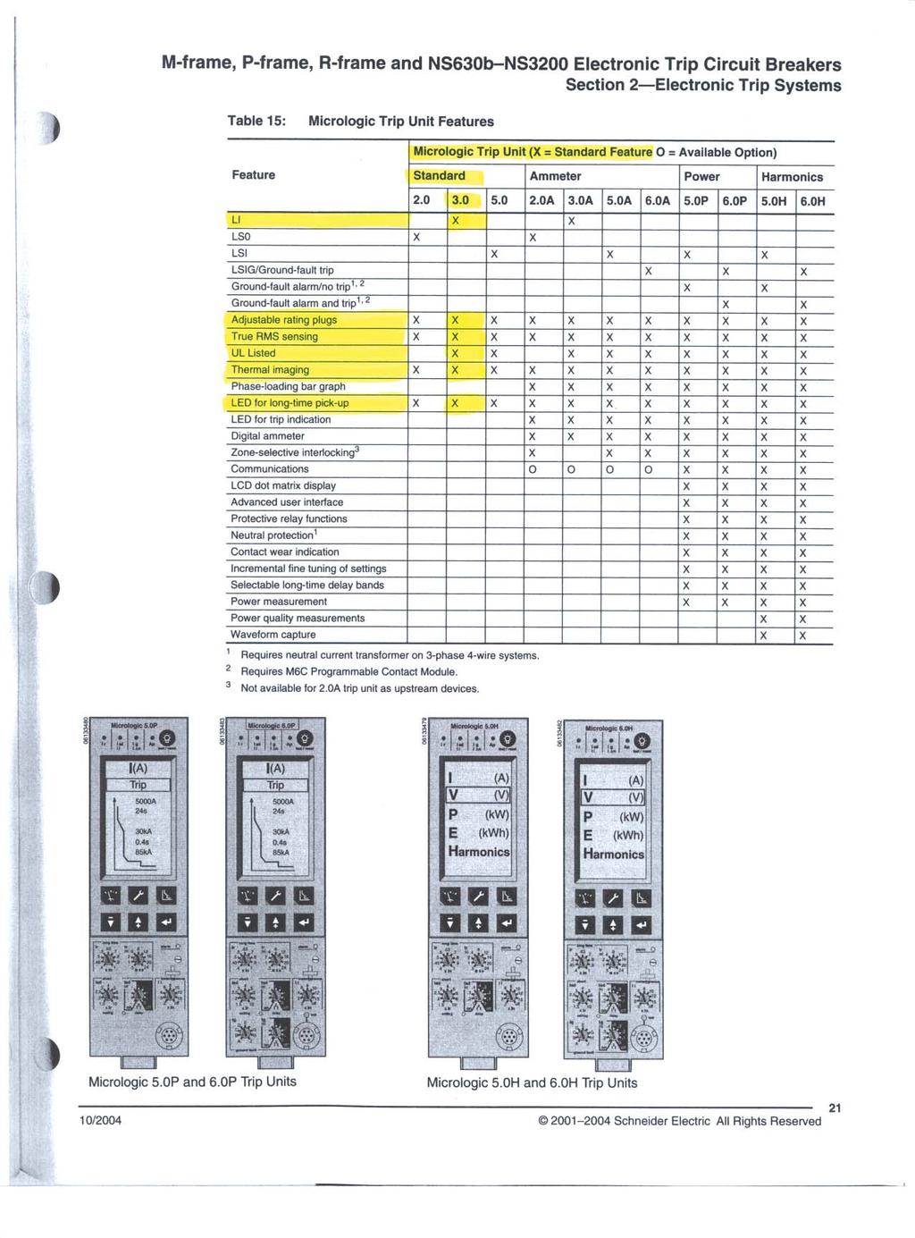
183
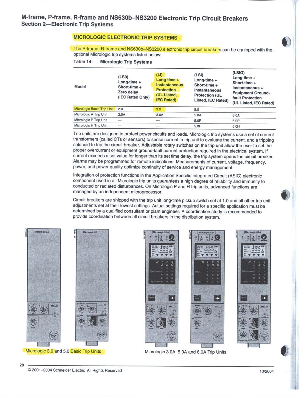
184
185
186
187
188 Batteries and accessories Quantity of 2 Battery Specifications Cold cranking amps Ship weight lbs Part number Battery Voltage Reserve capacity Length Width Height Group size Dry D Dry C Wet C Wet Dry Dry D Wet Dry Wet Wet D Sealed NA 12 NA NP Dry D Sealed Wet XL Dry NF Qts electrolyte 2013 Cummins Power Generation Inc. All rights reserved. Cummins Power Generation and Cummins are registered trademarks of Cummins Inc. Our energy working for you. is a trademark of Cummins Power Generation. Specifications are subject to change without notice. AC-150m (2/13) Page 1 of 5

189 NRG Intelligent Engine Start Battery Charger The Smart Choice for Mission-Critical Engine Starting Fast, accurate, mission-critical charging gives best starting reliability 4-rate, temperature-compensated output offers longest battery life Replace nearly any charger without planning ahead Industry-first battery-fault alarm helps dispatch service early Lasting reliability field MTBF > 1 million hours with industry-best warranty IBC seismic certification meets latest building codes, no installation delays S E C E R T I S M I F I C IBC I E D STORED ENERGY SYSTEMS info@sens-usa.com Toll-free

190 NRG Battery Charger Benefits and Features Failure to start due to battery problems is the leading cause of inoperable engine generator sets. SENS NRG battery charger maximizes starting system reliability while slashing genset servicing costs: One NRG replaces almost any charger without extra site visits. Installers can select or change at any time 120, 208 or 240 volts AC input, 12 or 24-volt battery and output settings optimized for nearly any lead-acid or nickel cadmium battery. Easy to understand user interface provides state-of-the-art system status including digital metering, NFPA 110 alarms and a battery fault alarm that can send service personnel to the site before failure to start. Batteries charged by NRG give higher performance and last longer. In uncontrolled environments precision charging by SENS increases battery life and watering intervals 400% or more. NRG meets all relevant industry standards including UL, NFPA 110 and CE. Seismic Certification per International Building Code (IBC) 2000, 2003, All units are C-UL listed. 50/60 Hz units add CE marking to UL agency marks. EnerGenius reliability technology built into every charger includes: All-electronic operation with generous component de-rating Disconnected/reversed/incorrect voltage battery alarm and protection Protection of connected equipment against load dump transients Widest temperature rating, and overtemperature protection Superior lightning and voltage transient protection Demonstrated field MTBF > 1 million hours Standard 3-year warranty (10 years magnetics and power semiconductors) and available 10-year complete warranty with reimbursement of field service costs Earn the best return on your charger investment choose SENS NRG
191 NRG Specifications AC Input Voltage Input current Frequency Input protection / VAC, +10%, single phase, field selectable 10A charger: 6.6/3.3 amps maximum 20A charger: 12.6/6.3 amps maximum 60 Hz +5% standard; 50/60 Hz +5% optional 1-pole fuse, soft-start, transient suppression Charger Output Nominal voltage ratings Optional voltage rating Battery settings Regulation Current Electronic current limit Charge characteristic Temperature compensation Output protection 12 or 24 volt nominal 12/24 volt, field selectable Six discrete battery voltage programs - Low or high S.G. flooded - Low or high S.G. VRLA - Nickel cadmium 9, 10, 18, 19 or 20 cells +0.5% (1/2%) line and load regulation 10 or 20 amps nominal 105% rated output typical no crank disconnect required Constant voltage, current limited, 4-rate automatic equalization Enable or disable anytime, remote sensor optional Current limit, 1-pole fuse, transient suppression Standard 4-rate charging User Interface, Indication and Alarms Digital meter Automatic meter alternately displays output volts, amps 4 Accuracy +2% volts, +5% amps Alarms LED and Form C contact(s) per table: Front panel status display 1. Alarms 1 available only on 10A charger 2. Form C contact provides summary alarm of these conditions. BBHH chargers include this alarm configuration. Contacts rated 30 VDC resistive 3. Battery fault alarm indicates these fault conditions: - Battery disconnected - Battery polarity reversed - Mismatched charger battery voltage - Open or high resistance charger to battery connection - Open battery cell or excessive internal resistance 4. Three-position jumper allows user to select from three display settings: alternating volts / amps (normal), constant volts, or constant amps

192 Controls AC input voltage select Optional 12/24-volt output select Battery program select Meter display select Fast charger enable/disable Temp compensation enable Remote temp comp enable Field-selectable switch Field-selectable two-position jumper Field-selectable six-position jumper Field-selectable three-position jumper Field-selectable two-position jumper Standard. Can be disabled or re-enabled in the field Connect optional remote sensor to temp comp port Simple field adjustments Environmental Operating temperature -20C to +60C, meets full specification to +45C Over temperature protection Gradual current reduction to maintain safe power device temperature Humidity 5% to 95%, non-condensing Vibration (10A unit) UL 991 Class B (2G sinusoidal) Transient immunity ANSI/IEEE C62.41, Cat. B, EN heavy industrial, EN Seismic Certification IBC 2000, 2003, 2006 Maximum S ds of 2.28 g Agency Standards Safety C-UL listed to UL 1236 (required for UL 2200 gensets), CSA standard 22.2 no M89 CE: 50/60 Hz units DOC to EN Agency marking 60 Hz: C-UL-US listed 50/60 Hz: C-UL-US listed plus CE marked EMC Emissions: FCC Part 15, Class B; EN Immunity: EN NFPA standards Optional agency compliance NFPA 70, NFPA 110. (NFPA 110 requires Alarms C ) Units with Alarms 1 configuration available with additional compliance to UL category BBHH and NFPA 20 Construction Housing/configuration Packaging Dimensions Printed circuit card Cooling Protection degree Damage prevention Electrical connections Material: Non-corroding aluminum. Configuration options: Fully enclosed: C-UL listed enclosure Open frame: C-UL recognized Open-frame and Slimline configurations only available in bulk OEM quantities and packaging See Drawings and Dimensions page for details Surface mount technology, conformal coated Natural convection Listed housing: NEMA-1 (IP20). Optional IP21 drip shield. Optional NEMA 3R enclosure Fully recessed display and controls Compression terminal blocks Warranty Standard warranty Optional warranty Three year parts and labor warranty (10 years magnetics and power semiconductors) from date of shipment If specified at time of order, warranty coverage can be increased to reimburse customer s documented field service costs up to the original charger price or increased to 5 or 10 years with field service cost reimbursement. Contact the factory for full details Optional features Input Input frequency, 50/60 Hz Remote temp comp sensor Recommended where battery and charger are in different locations Drip shield meets s/b (IP21) Protects from dripping water NEMA 3R housing Enables outdoor installation (remote temp sensor recommended) UL BBHH listing Available in 10A units with Alarms 1 Field service warranty Reimbursement of customer field service expenses up to charger price for 3, 5, or 10 years
193 Drawings and Dimensions 10A Chargers 20A Chargers
194 E All models offer field-selectable input 120/ volts. 60 Hz input is standard with C-UL listing. Optional 50/60 Hz input includes C-UL listing and adds CE mark. UL category code S: UL category BBGQ (standard) H: UL category BBHH (Alarms 1 only) Model Output voltage Output current 12: 12 volts 10: 10 amps 24: 24 volts 20: 20 amps 22: 12/24-volt field selectable AC input R: 120/ VAC, 60 Hz H: 120/ VAC, 50/60 Hz Alarm system code 1: LED and single Form C contact C: LEDs and Form C contacts to meet NFPA 110 Housing/Agency L: Enclosed: C-UL listed The Smart Choice for Mission-Critical Engine Starting Additional Information Contact SENS or your local sales representative for additional specification, engineering and installation information. Check the SENS web site for latest available data. Specification is subject to change without notice. S E I S M I C IBC 2000 C E R T I F I E D Contact Information For information and service on any SENS product, please contact us at: Sales Fax info@sens-usa.com 1840 Industrial Circle, Longmont, CO USA STORED ENERGY SYSTEMS
195 SENS EnerGenius Technical Manual 4. NEUTRAL CONNECTION The grounded circuit conductor (neutral) should be connected to the terminal marked N on the input terminal block, TB1. 5. WIRE RATINGS A. All conductors should be rated for use at 90º C or higher. B. All input and output conductor sizes should be coordinated with the fault protection devices: 10A on AC input (14 AWG, 2.5 mm 2 typical), 30A on DC output (10 AWG, 6.0 mm 2 typical). 1 A on Alarm terminal block (20 AWG, 0.5 mm 2 typical). C. Before installation, ensure adequate battery to charger wire gauge. Wire gauge that is too small may activate the open battery detector and the charger will shut down. The maximum allowed resistance seen by the charger is found in TABLE 1. These figures already include an allowance for charger variations (they are 80% of the typical trip-point) and are for the complete circuit: total of battery leads, battery's internal resistance, and any external equipment. The total resistance seen by the charger must not exceed the following values: TABLE 1 12V 24V Maximum Resistance 58m 116m D. To determine the appropriate cable and length, please refer to the following table: Wire Size Resistance per Foot TABLE 2 Maximum Charger to Battery Distance (Ft.) Recommended Charger to Battery Distance (Ft.) AWG mm 2 m/ft. 12V 24V 12V 24V The above lengths consider the resistance of the battery and cables only and do not take into account any additional interconnects. The above lengths are for operation at 25C. For high temperature installations (40C) reduce lengths by 10%. In the case of high resistance in the cables to the battery the charger may cycle between AC Fail and Battery Fault LEDs (approximately every 10 seconds). Cable runs exceeding the proper length for the cable gauge used most often cause this problem. The appropriate solution is to change the cable gauge to properly correspond with the necessary cable length (see TABLE 2). In some cases where the resistance is not too far above maximum, the charger may recover after some time (approximately 10 minutes) and start charging the batteries. If it is not possible to decrease the system resistance the Battery Fault feature can be disabled. Please contact SENS at for further information. E. Refer to local electrical codes for additional requirements. F. See Section 10 for Terminal Block wire ranges. 6. FUSE RATINGS A. CAUTION: For continued protection against risk of fire, replace only with same type and rating of fuse. B. DC Output Fuse SENS part number Bussman Type BK/ATC-30, or Littelfuse [ATO30], 30A, 32V, fast acting, blade type automotive C. AC Input Fuse SENS part number Bussman Type BK/AGC-10, 10A, 250VAC, fast acting, ferrule type cylindrical, ¼ X 1-¼ Service hotline:

196 PowerCommand Remote Annunciator Panel (LonWorks System annunciator) Description The PowerCommand Network Annunciator is a network component that provides remote system status indication for emergency and other power systems in compliance to the requirements of NFPA 110. The network annunciator may also be used for remote indication of any condition that is monitored by a PowerCommand Network. The Network Annunciator reduces installation costs and improves design flexibility by use of a PowerCommand Network to transmit all the genset and transfer switch system signals rather than using relay contacts for this purpose. Control power for PowerCommand Network products is usually derived from the genset starting batteries. The control functions over a voltage range from 8 VDC to 35 VDC. Features Visual indication of 20 network conditions and network status. Audible indication of any network condition - Annunciator also includes pushbutton switch to silence the audible alarm. Alarm horn sound level is approximately 90 db(a) at 30 cm. Standard NFPA 110 label, field configurable for other alarm and status conditions. Configurable for compliance to NFPA 99 requirements. Sealed membrane panel design provides environmental protection for internal components and is easy to clean. Warranty - PowerCommand Controls are supported by a worldwide network of independent distributors who provide parts, service and warranty support. UL Listed and labeled; CSA certified; CE marked. Wall mount NEMA 1 enclosure or flush mount configurations available. 2007Cummins Power Generation Inc.All rights reservedspecifications subject to change without noticecummins Power Generation and Cummins are registered trademarks of Cummins Inc. PowerCommand and Our energy working for you. are trademarks of Cummins Power Generation. Other company, product, or service names may be trademarks or service marks of others. S-1343e (9/07)
197 Specifications Signal requirements Network connections: Echelon LonWorks, twisted-pair 78 kbps, FT-10. Control power: 8-30 VDC, 3.5 W (maximum) 0.8 W typical. Wiring materials for network signals are UL Listed 4 twisted pair wiring. Terminations for control power accept wire up to 16 ga. Environment The annunciator is designed for proper operation in ambient temperatures from -40 C to +70 C (-40 F to +158 F) and for storage from -40 C to +80 C (-40 F to +176 F). Control will operate with humidity up to 95%, non-condensing and at altitudes up to 5000 m (13,000 ft). Alarm Horn Sound Level: 90 db(a) at 30 cm Physical Weight: 1.45 kg (3.2 lbs) (board plus enclosure) Power Maximum Consumption: 5 W Standby Consumption: 0.4 W or less Network Length: Maximum 1400 m (4600 ft), when using NEMA Level 4 cable Self-binding configurations - Supports use of up to four annunciators with up to one genset and one transfer switch. Maximum wire lengths - control power-self-binding system Wire size 12 VDC 24 VDC 22 ga 100 m (330 ft) 338 m (1100 ft) 20 ga 158 m (520 ft) 537 m (1760 ft) 18 ga 250 m (820 ft) 852 m (2790 ft) 16 ga 398 m (1300 ft) 1352 m (4430 ft) 14 ga 631 m (2070 ft) 1400 m (4600 ft) Dimensions Cut out detail (without enclosure) Annunciator enclosure Dimensions: in (mm) Our energy working for you Cummins Power Generation Inc.All rights reservedspecifications subject to change without noticecummins Power Generation and Cummins are registered trademarks of Cummins Inc. PowerCommand and Our energy working for you. are trademarks of Cummins Power Generation. Other company, product, or service names may be trademarks or service marks of others. S-1343e (9/07)
198 Label configurations & standard bindings NFPA 110 genset alarm and status annunciator The following conditions are provided as standard on the annunciator: High battery voltage (A) Pre-high coolant temperature (A) Battery charger malfunction (A) Low battery voltage (A) High coolant temperature (R) Low fuel (A) Genset running (G) Low engine temperature (A) Low coolant level (R) Genset supplying load (G) Overspeed (R) Spare (4) (G) Pre-low oil pressure (A) Fail to start (overcrank) (R) Common alarm Low oil pressure (R) Not in auto (R) (A) = Amber; (R) = Red; (G) = Green Extended genset alarm and status annunciator The following conditions are provided as standard on the annunciator: Check genset (R) Over current (R) Load demand (G) Ground fault (A) Short circuit (R) Genset CB tripped (R) High AC voltage (R) Reverse KW (R) Utility CB tripped (R) Low AC voltage (R) Reverse kvar (R) Emergency stop (R) Under frequency (R) Fail to sync (A) Spare (4) (G) Overload (R) Fail to close (R) (A) = Amber; (R) = Red; (G) = Green 8-Point (genset) The following conditions are provided as standard on the annunciator: Check genset (A) Not in auto (G) Low coolant level (R) Genset supplying load (A) High/low engine temp (G) Low fuel level (A) Genset running (G) Low oil pressure (A) Spare (8) (G) (A) = Amber; (R) = Red; (G) = Green 4-Point (genset) The following conditions are provided as standard on the annunciator: Check genset (A) Not in auto (G) Genset supplying load (A) Spare (16) (G) Genset running (G) (A) = Amber; (R) = Red; (G) = Green ATS-extended This annunciation set is often used with PLT-series equipment. The following conditions are provided as standard on the annunciator: Source 1 available (G) ATS not in auto Fail to close Source 2 available (G) Test/exercise Fail to disconnect Source 1 connected (G) Transfer pending Fail to synchronize Source 2 connected (G) Load shed Low battery-controller Check ATS (R) Transfer inhibit Low battery-network (A) = Amber; (R) = Red; (G) = Green ATS 8-point The following conditions are provided as standard on the annunciator: Source 1 available (G) Source 2 connected (G) Test/exercise mode (A) Source 2 available (G) Common alarm (A) Low control battery (A) Source 1 connected (G) Not in auto (R) Spare (8) (G) (A) = Amber; (R) = Red; (G) = Green ATS 4-point The following conditions are provided as standard on the annunciator: Source 1 available (G) Source 2 connected (G) Source 2 available (G) Source 1 connected (G) (A) = Amber; (R) = Red; (G) = Green Our energy working for you Cummins Power Generation Inc.All rights reservedspecifications subject to change without noticecummins Power Generation and Cummins are registered trademarks of Cummins Inc. PowerCommand and Our energy working for you. are trademarks of Cummins Power Generation. Other company, product, or service names may be trademarks or service marks of others. S-1343e (9/07)
199 Custom alarm configuration # Color (R/Y/G) Label Horn (Y/N) # Color (R/Y/G) Label Horn (Y/N) Ordering information Part number Description Network annunciator, open construction, for panel mounting Network annunciator including control box for surface wall mounting See your distributor for more information. Cummins Power Generation Americas rd Avenue N.E. Minneapolis, MN USA Phone: USA Fax: Our energy working for you. Europe, CIS, Middle East and Africa Manston Park Columbus Ave. Manston Ramsgate Kent CT 12 5BF United Kingdom Phone Fax Cummins Power Generation Inc.All rights reservedspecifications subject to change without noticecummins Power Generation and Cummins are registered trademarks of Cummins Inc. PowerCommand and Our energy working for you. are trademarks of Cummins Power Generation. Other company, product, or service names may be trademarks or service marks of others. S-1343e (9/07) Asia Pacific 10 Toh Guan Road #07-01 TT International Tradepark Singapore Phone Fax

200 PowerCommand ModLon II Gateway ModBus - LON Converter Description The PowerCommand ModLon II Gateway is used to interface PowerCommand Networks to devices and systems that communicate in Modbus communication protocol. The ModLon II Gateway provides an Echelon LonWorks to Modbus RTU or Modbus ASCII conversion via an RS232 serial connection. The gateway supplies predefined registers for PowerCommand Network components. Selection of the gateway configuration is done by setting the dipswitches on the device. Features Converts Echelon LonWorks data streams to register maps that can be read by equipment communicating in Modbus RTU and Modbus ASCII format. FTT-10 transceiver. Modbus port EIA-232 configuration. Capable of displaying data from PowerCommand Generator set controls, transfer controls, CCM and DIM modules. Service button, reset button and LED indicators. Configured to PowerCommand networks using Echelon LonMaker for Windows. Operates on 9-32 VDC. CE and UL Listed and labeled. Warranty: PowerCommand Controls are supported by a worldwide network of independent distributors who provide parts, service and warranty support. 2008Cummins Power Generation Inc.All rights reservedspecifications subject to change without noticecummins Power Generation and Cummins are registered trademarks of Cummins Inc. PowerCommand and Our energy working for you. are trademarks of Cummins Power Generation. Other company, product, or service names may be trademarks or service marks of others. S-1471c (6/08)
201 Specifications Signal requirements Network connections: Echelon LonWorks, twisted-pair 78 kbps, FTT-10. Control power: 9-32 VDC. Wiring materials for network signals are UL Listed twisted pair wiring. Terminations for control power accept wire up to 16 ga. Modbus connections: EIA-232 with DB-9 (female) physical connection. Physical Weight: 0.11 kg (0.245 lbs) Power Current draw: 9 VDC = 0.15 A, 24 VDC = 0.06 A Baud: Configurable through LonWorks Parity: Configurable through LonWorks Word length: Configurable through LonWorks Stop bits: Configurable through LonWorks Network length: Connects to LonWorks network of maximum 1400 m (4600 ft) using UL/NEMA Level 4 cable. Environment The gateway module is designed for proper operation in ambient temperatures from 0 C to +50 C (32 F to +122 F) and for storage from -20 C to +60 C (-4 F to +140 F). Data and configurations Control type data available PCC 2100, PCC 3100, PCC 3200, CCM (genset) - Fault messages, state, 3-phase L-L and L-N voltages, 3-phase amps, frequency, percent amps, power factor, kw, percent kw, kvar, kw-hr, oil pressure, oil temperature (when available), coolant temperature, exhaust temperature (when available), DC volts, runtime hours, number of starts, engine rpm. PowerCommand transfer switches - Fault messages, 3- phase L-L and L-N voltages and frequency for each source, transfer switch position, load amps, power factor, kw, kvar. Control Communication Module: CCM (ATS) - Fault messages, 3-phase L-L and L-N voltages and frequency for load, transfer switch position, load amps, power factor, kw, kvar. Digital I/O Module: DIM - Status of up to 16 discrete output conditions, and 8 discrete input conditions. Template configuration (selected through dipswitches) 1 5 genset controls (any type or combination), 5 transfer switches (any type or combination) and two DIM modules. 2 5 genset controls (any type or combination) including paralleling data, 5 transfer switches (any type or combination) and two DIM modules. 3a 10 genset controls (any type or combination), including paralleling data. 3b 10 transfer switch controls (any type or combination). 5 5 genset controls (any type or combination), 5 transfer switches (any type or combination) and 2 DIM modules. Register map is identical to ModLon map for TP-78 PowerCommand Network devices. Our energy working for you Cummins Power Generation Inc.All rights reservedspecifications subject to change without noticecummins Power Generation and Cummins are registered trademarks of Cummins Inc. PowerCommand and Our energy working for you. are trademarks of Cummins Power Generation. Other company, product, or service names may be trademarks or service marks of others. S-1471c (6/08)
202 Typical register map for generator sets (see instruction sheet for complete maps) Modbus registers Scaling Structure Data point GEN [0] GEN [1] GEN [2] GEN [3] GEN [4] Multiplier Units Name [0,1] nvogenstatus Name [2,3] Name [4,5] Name [6,7] Name [8,9] Name [10,11] Name [12,13] Name [14,15] Device type Control switch State Fault code* Fault type Percent kw % Total kw NFPA Extended Frequency Hz nvogenacdata Total pf PF Total kva KVA Total kw KW Total kvar KVAR Volts ab Volts Volts bc Volts Volts ca Volts Volts a Volts Volts b Volts Volts c Volts Amps a Amps Amps b Amps Amps c Amps Percent amps a % Percent amps b % Percent amps c % Battery voltage Volts DC nvogenengdata Oil pressure KPA Oil temp Deg Kelvin Coolant temp Deg Kelvin Misc temp Deg Kelvin Misc temp Deg Kelvin Fuel rate GPH Engine RPM RPM Engine starts starts Eng runtime (high) 1, Eng runtime (low) Sec Total kwh (high) Total kwh (low) kwh Total fuel (high) 1, Total fuel (low) Gal Genset control Start/stop Reset * Fault codes are listed in the generator set operator/service manuals. Our energy working for you Cummins Power Generation Inc.All rights reservedspecifications subject to change without noticecummins Power Generation and Cummins are registered trademarks of Cummins Inc. PowerCommand and Our energy working for you. are trademarks of Cummins Power Generation. Other company, product, or service names may be trademarks or service marks of others. S-1471c (6/08)
203 NFPA 110 description Bit Extended description Bit Common alarm 0 (MSB) Check genset 0 (MSB) Genset supplying load 1 Ground fault 1 Genset running 2 High AC voltage 2 Not in auto 3 Low AC voltage 3 High battery voltage 4 Under frequency 4 Low battery voltage 5 Overload 5 Charger AC failure 6 Overcurrent 6 Fail to start 7 Short circuit 7 Low coolant temperature 8 Reverse KW 8 Pre-high engine temperature 9 Reverse KVAR 9 High engine temperature 10 Fail to sync 10 Pre-low oil pressure 11 Fail to close 11 Low oil pressure 12 Load demand 12 Over speed 13 Genset circuit breaker tripped 13 Low coolant level 14 Utility circuit breaker tripped 14 Low fuel level 15 (LSB) Emergency stop 15 (LSB) Dimensions Notes: 1 For the data points engine runtime, the total kwh and total fuel for the two registers designated as high and low are put together as an unsigned double integer. This is accomplished by multiplying the value in the high register by and adding it to the value in the low register. Most software packages automatically perform this calculation if the value is simply identified as an unsigned double integer. 2 Value not supported in the 3200 controller. 3 Value not supported in the 3100 controller. 4 Value not supported. 5 With 3100 and 2100 controllers, the units are hours. With the 3200 controller, the units are seconds. The multiplier is always 0.1 For all 3100 controllers, the values given are based on using EEPROM firmware, version 2.0 or greater. The values for engine runtime and total kwh are not available on QST 30 gensets. Ordering information Part number Description ModLon II Gateway, CD, instructions, cable See your distributor for more information. Cummins Power Generation Americas rd Avenue N.E. Minneapolis, MN USA Phone: Fax: Europe, CIS, Middle East and Africa Manston Park Columbus Ave. Manston Ramsgate Kent CT 12 5BF United Kingdom Phone Fax Asia Pacific 10 Toh Guan Road #07-01 TT International Tradepark Singapore Phone Fax Our energy working for you Cummins Power Generation Inc.All rights reservedspecifications subject to change without noticecummins Power Generation and Cummins are registered trademarks of Cummins Inc. PowerCommand and Our energy working for you. are trademarks of Cummins Power Generation. Other company, product, or service names may be trademarks or service marks of others. S-1471c (6/08)
204 Preventative Maintenance Kits kw Generator sets Description Features Cummins Power Generation Preventative Maintenance kits include our state-of-the-art technology in oil, fuel, and air filtration. These components meet or exceed specifications for maximum quality and performance. We custom-design high end systems for engine lubricating oil, fuel, and air filtering. These performance-tested systems feature a variety of media with particle retention capabilities to micrometer filtration that enhance protection without sacrificing quality. CPG provides the filtration products that you need to protect and maintain modern engines. Oil - Lube oil is an essential to life of your engine. lt lubricates, and protects engine components. Since contaminants enter the lube system due to engine wear, it is vital that you use the best quality oil filtration. Fuel - With filtration requirements as low as 2 microns on some high pressure common rail (HPCR) fuel systems, and new fuels like ultra low sulfur diesel, it is imperative that you have the best quality fuel filtration. Air - Clean air is essential to the performance and longevity of any internal combustion engine. With increasingly stricter levels of emissions having to be met, it s imperative that you use the best quality air filtration. Coolant - Fully formulated coolants contain specific amounts of glycol, de-ionized water, and coolant additives. Over time contaminants enter the cooling system making it imperative to use the best quality coolant filtration. 250 Hours or 6 months run time Increased uptime Enhanced fuel economy Lower Operating costs Environmental safety Reliability and durability Highest performance Optimized performance Convenience of ordering with generator Prolonged engine life Reduced maintenance costs 2012 Cummins Power Generation Inc. All rights reserved. Cummins Power Generation and Cummins are registered trademarks of Cummins Inc. Our energy working for you. is a trademark of Cummins Power Generation. Specifications are subject to change without notice. NAAC-5489b-EN (11/12)
205 Genset Model Engine Model PM Kit Part Number Normal Duty Air Cleaner PM Kit Part Number Heavy Duty Air Cleaner DFE's QSX15L-G9 NR2 A041C902 A041C904 DFH's QST30-G1 A041D162 A041D167 DFLC KTA50-G3 A041D198 NA DFLE KTA50-G9 A041D205 A041D221 DGB's 4B3.9-G2 A041C225 NA DGC s 4BT3.9-G4 NA A041C669 DGCG 4BTA3.9-G3 A041C671 NA DGDB 6BT5.9-G6 A041C772 NA DGDK 6BTA5.9-G3 A041C775 NA DGFA/B 6CTA8.3-G2 A041C806 NA DGFC/S 6CTAA8.3-G2 NA A041C806 DGH s 4BT3.3-G5/G7 A044C436 NA DKA s F2803-E2BG A041B930 NA DQC's QSK23-G3/G7 NR2 A041D139 A041D143 DQDA's QSL9-G3 A041C870 A041C874 DQFA's QST30-G5 NR2 A041D169 A041D187 DQGA s QSK50-G4 NR2 A041D225 NA DQGAC QSK50-DR (Oil & Gas) NA A041D335 DQHA's QSM11-G4 NR3 A041C889 A041C891 DQKAA/B QSK60-G6 (A034D142) A041D324 NA DQKAA/B QSK60-G6 ( ) NA NA DQKAD/E/F QSK60-G6/G14 NA NA DQKB/C QSK60-G3 (hi cap oil) A041D318 NA DQKB/C/D/H QSK60-G4/G6/G8 A041D316 NA DQKH QSK60-G9 A041D322 NA DQLD QSK78-G8 NR1 A042W151 A041D331 DQLE/F QSK78-G11/12 A042W151 A042W153 DFLK KTA50-DR (Oil & Gas) NA A041D344 DQMAA QSK19-G3 NR2 A041C934 A041C936 DSFA's QSB5-G3 A041C704 NA DSGAA QSB7-G3/G5 NR3 NA A041C792 DSHA's QSL9-G2 A041C870 A041C874 DSKAA/AB/BA D1703-M-E3BG NA A041B934 DSKCA V3300-E3BG NA A041B936 GGHE/F WSG A A041B979 A041B983 GGHG/H WSG A A041B987 NA GGL's GM 8.1L V8 Turbo A041C802 NA GGM's GM 3.0L (HO) A041B943 A041B947 GGP's GM 5.0L A041B957 A041B Cummins Power Generation Inc. All rights reserved. Cummins Power Generation and Cummins are registered trademarks of Cummins Inc. Our energy working for you. is a trademark of Cummins Power Generation. Specifications are subject to change without notice. NAAC-5489b-EN (11/12)
206 Limited Standby 5 Year or 1,500 hour Comprehensive Extended Warranty L031 Commercial Generating Set When purchased, this limited extended warranty applies to Cummins Power Generation branded commercial generating sets and associated accessories (hereinafter referred to as "Product"). This warranty covers any failures of the Product, under normal use and service, which result from a defect in material or factory workmanship. Warranty Period: The warranty start date is the date of initial start up, first rental, demonstration or 18 months after factory ship date, whichever is sooner. The coverage duration is 5 years from warranty start date or 1,500 hours or whichever occurs first. Emergency Standby Power (ESP) is defined as the maximum power available during a variable electrical power sequence, under the stated operating conditions, for which a generating set is capable of delivering in the event of a utility power outage. The permissible average power output over 24 hours of operation shall not exceed 70% of the ESP. Cummins Power Generation Responsibilities: In the event of a failure of the Product during the extended warranty period due to defects in material or workmanship, Cummins Power Generation will only be responsible for the following costs: All parts and labor required to repair the Product. Reasonable travel expenses to and from the Product site location. Maintenance items that are contaminated or damaged by a warrantable failure. Owner Responsibilities: The owner will be responsible for the following: Notifying Cummins Power Generation distributor or dealer within 30 days of the discovery of failure. Installing, operating, commissioning and maintaining the Product in accordance with Cummins Power Generation s published policies and guidelines. Providing evidence for date of commissioning. Providing sufficient access to and reasonable ability to remove the Product from the installation in the event of a warrantable failure. In addition, the owner will be responsible for: Incremental costs and expenses associated with Product removal and reinstallation resulting from non-standard installations. Costs associated with rental of generating sets used to replace the Product being repaired. Costs associated with labor overtime and premium shipping requested by the owner. All downtime expenses, fines, all applicable taxes, and other losses resulting from a warrantable failure. Limitations: This limited extended warranty does not cover Product failures resulting from: Inappropriate use relative to designated power rating. Inappropriate use relative to application guidelines. Normal wear and tear. Improper and/or unauthorized installation. Owner s or operator s negligence, accidents or misuse. Lack of maintenance or unauthorized repair. Noncompliance with any Cummins Power Generation published guideline or policy. Use of improper or contaminated fuels, coolants or lubricants. Improper storage before and after commissioning. Owner s delay in making Product available after notification of potential Product problem. Effective Date: 01-October-2009 Page 1 of 2
207 Use of steel enclosures within 60 miles of the coast of salt water when aluminum or an alternate non-corrosive material enclosure option is available. Replacement parts and accessories not authorized by Cummins Power Generation. Use of Battle Short Mode. Owner or operator abuse or neglect such as: operation without adequate coolant or lubricants; overfueling; overspeeding; lack of maintenance to lubricating, cooling or air intake systems; late servicing and maintenance; improper storage, starting, warm-up, run-in or shutdown practices, or for progressive damage resulting from a defective shutdown or warning device. Damage to parts, fixtures, housings, attachments and accessory items that are not part of the generating set. This limited extended warranty does not cover costs resulting from: Difficulty in gaining access to the Product. Repair of cosmetic damage to enclosures. Items not covered by this limited extended warranty: Batteries Enclosures Coolant heating elements Maintenance items Aftertreatment component failures. CUMMINS POWER GENERATION RIGHT TO FAILED COMPONENTS: Failed components claimed under warranty remain the property of Cummins Power Generation. Cummins Power Generation has the right to reclaim any failed component that has been replaced under warranty. THE WARRANTIES SET FORTH HEREIN ARE THE SOLE WARRANTIES MADE BY CUMMINS POWER GENERATION IN REGARD TO THE PRODUCT. CUMMINS POWER GENERATION MAKES NO OTHER WARRANTIES, EXPRESS OR IMPLIED, OR OF MERCHANTABILITY OR FITNESS FOR A PARTICULAR PURPOSE. IN NO EVENT IS CUMMINS POWER GENERATION LIABLE FOR INCIDENTAL OR CONSEQUENTIAL DAMAGES. This limited extended warranty shall be enforced to the maximum extent permitted by applicable law. This limited extended warranty gives the owner specific rights that may vary from state to state or from jurisdiction to jurisdiction. Product Model Number: Product Serial Number: Date in Service: Effective Date: 01-October-2009 Page 2 of 2
208 OTPC transfer switch open and closed transition Amp Description OTPC transfer switches are designed for operation and switching of electrical loads between primary power and standby generator sets. They are suitable for use in emergency, legally required and optional standby applications. The switch monitors both power sources, signals generator set startup, automatically transfers power, and returns the load to the primary power source when the utility returns and stabilizes. OTPC transfer switches are available with closed transition transfer. By briefly connecting the two sources (for 100 msec or less), the transfer from the alternate source back to the normal source occurs without interruption in the power supply to loads. NEC All switches are UL 1008 Listed with UL Type Rated cabinets and UL Listed CU-AL terminals. All switches are certified to CSA 282 Emergency Electrical Power Supply for Buildings, up to 600 VAC. Suitable for use in emergency, legally required and standby applications per NEC 700, 701 and 702. All switches comply with NFPA 70, 99 and 110 (Level 1). All switches comply with NEMA ICS 10. All switches comply with IEEE 446 Recommended Practice for Emergency and Standby Power Systems. This transfer switch is designed and manufactured in facilities certified to ISO9001. Features PowerCommand control - A fully featured microprocessor-based control with digital display. Controls allow operator to enter settings and make adjustments to software-enabled features easily and accurately. Accommodates up to eight event schedules. Programmed transition Open transition timing can be adjusted to completely disconnect the load from both sources for a programmed time period, as recommended by NEMA MG-1 for transfer of inductive loads. Advanced transfer switch mechanism Unique bidirectional linear actuator provides smooth, continuous transfer switch action during automatic operation. Robust control system design - Optically isolated logic inputs and isolation transformers for AC power inputs provide high-voltage surge protection. Main contacts - Heavy-duty silver alloy contacts with multi-leaf arc chutes are rated for 100% load interruption. They require no routine contact maintenance and provide 100% continuous current ratings. Communications capability - The transfer switch is capable of communicating with other transfer switches, SCADA and remote monitoring systems, or Cummins Power Generation generators utilizing LonWorks protocol. Easy service/access - Single-plug harness connection and compatible terminal markings simplify servicing. Access space is ample. Door-mounted controls are field-programmable; no tool is required. Complete product line - Cummins Power Generation offers a wide range of equipment, accessories and services to suit virtually any backup power application. Warranty and service - Products are backed by a comprehensive warranty and a worldwide network of distributors with factory-trained service technicians Cummins Power Generation Inc. All rights reserved. Cummins Power Generation and Cummins are registered trademarks of Cummins Inc. PowerCommand and Our energy working for you. are trademarks of Cummins Power Generation. Other company, product, or service names may be trademarks or service marks of others. Specifications are subject to change without notice. S-1270ad (5/12)
209 Transfer switch mechanism Specifications Voltage rating Arc interruption Neutral bar Auxiliary contacts Our energy working for you. Transfer switch mechanism is electrically operated and mechanically held in the Source 1 and Source 2 positions. The transfer switch incorporates electrical and mechanical interlocks to prevent inadvertent interconnection of the sources. Independent break-before-make action is used for both 3-pole and 4-pole/ switched neutral switches. This design allows use of sync check operation when required, or control of the operating speed of the transfer switch for proper transfer of motor and rectifier-based loads (programmed transition feature). True 4-pole switching allows for proper ground (earth) fault sensing and consistent, reliable operation for the life of the transfer switch. The neutral poles of the transfer switch have the same ratings as the phase poles and are operated by a common crossbar mechanism, eliminating the possibility of incorrect neutral operation at any point in the operating cycle, or due to failure of a neutral operator. High pressure silver alloy contacts resist burning and pitting. Separate arcing surfaces further protect the main contacts. Contact wear is reduced by multiple leaf arc chutes that cool and quench the arcs. Barriers separate the phases to prevent interphase flashover. A transparent protective cover allows visual inspection while inhibiting inadvertent contact with energized components. Switch mechanism, including contact assemblies, is third party certified to verify suitability for applications requiring high endurance switching capability for the life of the transfer switch. Withstand and closing ratings are validated using the same set of contacts, further demonstrating the robust nature of the design. 600 VAC, 50 or 60 Hz. Multiple leaf arc chutes provide dependable arc interruption. Operating temperature -40 F (-40 C) to 140 F (60 C) Storage temperature -40 F (-40 C) to 140 F (60 C) Humidity Altitude Surge withstand ratings Total transfer time (sourceto-source) Manual operation handles A full current-rated neutral bar with lugs is standard on enclosed 3-pole transfer switches. Two isolated contacts (one for each source) indicating switch position are provided for customer use. Contacts are normally open, and close to indicate connection to the source. Wired to terminal block for easy access. Rated at 10 amps continuous and 250 VAC maximum. UL recognized, and CSA-certified. Up to 95% relative, non-condensing Up to 10,000 ft (3,000 m) without derating Voltage surge performance and testing in compliance with the requirements of IEEE C62.41 (Category B3) and IEEE C Will not exceed 6 cycles at 60 Hz with normal voltage applied to the actuator and without programmed transition enabled. Transfer switches rated through 1000 amps are equipped with permanently attached operating handles and quick-break, quick-make contact mechanisms suitable for manual operation. Transfer switches over 1000 amps are equipped with manual operators. All switches must be de-energized before manual operation is attempted. Transition modes Open transition/programmed: Controls the time required for the device to switch from source to source, so that the load-generated voltages decay to a safe level before connecting to an energized source. Recommended by NEMA MG- 1 to prevent nuisance-tripping breakers and load damage. Adjustable 0-60 seconds, default 0 seconds. Programmed transition is standard on amp switches, and optional on amps. Open transition/in-phase: Initiates open transition transfer when in-phase monitor senses both sources are in phase. Operates in a break-before-make sequence. Includes ability to enable programmed transition as a back-up. If sources are not in phase within 120 seconds, switches from amps will transfer using programmed transition (not available on open transition switches over 1200 amps). Closed transition: Used in applications where loads are sensitive to the momentary power interruption that occurs when performing open transition between sources. Closed transition is accomplished by briefly (<100 msec) paralleling two good sources to eliminate the momentary break in the power supply. Closed transition is only available as an option on OTPC models from amps. Genset-to-genset: Either genset can be designated as the lead genset. If the lead genset goes down or is taken offline, the transfer switch starts the second genset and transfers the load. The control can be programmed to alternate between the two gensets at a set interval up to 336 hours (2 weeks) Cummins Power Generation Inc. All rights reserved. Cummins Power Generation and Cummins are registered trademarks of Cummins Inc. PowerCommand and Our energy working for you. are trademarks of Cummins Power Generation. Other company, product, or service names may be trademarks or service marks of others. Specifications are subject to change without notice. S-1270ad (5/12)
210 PowerCommand control PowerCommand controls are microprocessor based and developed specifically for automatic transfer switch operation. The control includes all of the features and options required for most applications. LED lamps indicate source availability, source connected, exercise mode and test mode. Flash memory stores the control settings. Contents of the memory are not lost even if power to the controller is lost. On-board battery maintains the real-time clock setting and the engine start time delay. Choice of two control packages allows selection of the most suitable control for the application. Control functions Level 1 control (C023) Level 2 control (C024) Open transition (in-phase) Open transition (in-phase) Open transition (programmed) Open transition (programmed) Utility-to-genset applications Closed transition (includes fail-to-disconnect timer to prevent Software adjustable time delays: extended paralleling with the utility) Engine start: 0 to 120 sec Utility-to-genset applications Transfer normal to emergency: 0 to 120 sec Utility-to-utility applications Re-transfer emergency to normal: 0 to 30 min Genset-to-genset applications Engine stop: 0 to 30 min Software adjustable time delays: Programmed transition: 0 to 60 sec Engine start: 0 to 120 sec Undervoltage sensing: 3-phase normal, 1-phase emergency Transfer normal to emergency: 0 to 120 sec Accuracy: =/- 2% Re-transfer emergency to normal: 0 to 30 min Pickup: 85% to 100% of nominal voltage Engine stop: 0 to 30 min Dropout: 75% to 98% of pickup setting Programmed transition: 0 to 60 sec Dropout time delay: 0-4 sec Undervoltage sensing: 3-phase normal, 3-phase emergency Overvoltage sensing: 3-phase normal, 1-phase emergency Accuracy: +/- 2% Accuracy: =/- 2% Pickup: 85% to 100% of nominal voltage Pickup: 95% to 99% of dropout setting Dropout: 75% to 98% of pickup setting Dropout: 105% to 135% of nominal voltage Dropout time delay: 0-4 sec Dropout time delay: 0 to 120 sec Overvoltage sensing: 3-phase normal, 3-phase emergency Over/under frequency sensing: Accuracy: ±2% Accuracy: ±0.05 Hz Pickup: 95% to 99% of dropout setting Pickup: ±5% to ±20% of nominal frequency Dropout: 105% to 135% of nominal voltage Dropout: 1-5% beyond pickup Dropout time delay: 0 to 120 sec Dropout time delay: 0.1 to 15.0 sec Over/under frequency sensing: Programmable genset exerciser: One event/schedule with or Accuracy: =/ Hz w/o load Pickup: ±5% to ±20% of nominal frequency Basic indicator panel: Dropout: 1-5% beyond pickup Source available/connected LED indicators Dropout time delay: 0.1 to 15.0 sec Test/exercise/override buttons Voltage imbalance sensing: Digital display optional (M018) Dropout: 2% to 10% Analog bar graph meter display optional (D009) Pickup: 90% of dropout Date/time-stamped event recording: 50 events Time delay: 2.0 to 20.0 sec Load sequencing: Optional with network communications Phase rotation sensing: module M031. Provides control for eight steps of load with an Time delay: 100 msec adjustable time delay for each step on transfer, re-transfer or Loss of single phase detection: both. Time delay: 100 msec Programmable genset exerciser: Eight events/schedules with or w/o load Basic indicator panel: Source available/connected LED indicators Test/exercise/override buttons Digital display standard Analog bar graph meter display optional (D009) Date/time-stamped event recording: 50 events Load sequencing: Optional with network communications module M031. Provides control for eight steps of load with an adjustable time delay for each step on transfer, re-transfer, or both. Genset-to-genset: Same functions as above, for lead and secondary generators. Utility-to-utility: Same functions as above, for preferred and alternate source. Our energy working for you Cummins Power Generation Inc. All rights reserved. Cummins Power Generation and Cummins are registered trademarks of Cummins Inc. PowerCommand and Our energy working for you. are trademarks of Cummins Power Generation. Other company, product, or service names may be trademarks or service marks of others. Specifications are subject to change without notice. S-1270ad (5/12)
211 Time-delay functions Engine start: Prevents nuisance genset starts due to momentary power system variation or loss. Not included in utility-to-utility systems. Transfer normal to emergency: Allows genset to stabilize before application of load. Prevents power interruption if normal source variation or loss is momentary. Allows staggered transfer of loads in multiple transfer switch systems. For genset-to-genset applications, delays transfer of load from lead to secondary generator. Re-transfer emergency to normal: Allows the utility to stabilize before re-transfer of load. Prevents needless power interruption if return of normal source is momentary. Allows staggered transfer of loads in multiple transfer switch systems. For genset-to-genset applications, delays re-transfer of load from secondary back to lead generator. Engine stop: Maintains availability of the genset for immediate reconnection if the normal source fails shortly after retransfer. Allows gradual genset cool down by running unloaded. Not included in utility-to-utility systems. Elevator pre-transfer signal: Requires optional relay signal module (M023). Signals elevator system that transfer is pending and delays transfer for pre-set interval of 0-60 seconds to prevent a power interruption during elevator operation. User interfaces Basic interface panel LED indicators provide at-a-glance source and transfer switch status for quick summary of system conditions. Test and override buttons allow delays to be bypassed for rapid system checkout. Digital display (M018) The digital display provides a convenient method for monitoring load power conditions, adjusting transfer switch parameters, monitoring PowerCommand network status or reviewing transfer switch events. Password protection limits access to adjustments to authorized personnel. The digital display is optional with the PowerCommand Level 1 control and comes standard with the Level 2 control. User interface options Front panel security key (M017) Locks front panel to prohibit access to digital control settings. Prevents unauthorized activation of transfer or test functions. Bar graph meter display (D009) An LED bar graph display provides an easy-to-read indicator of the level of power being supplied to the load. Information displayed includes: 3-phase voltage and current, frequency, power factor, and kilowatts. Green, amber, and red LEDs provide at-a-glance indication of system acceptability. Available as an option with the Level 2 PowerCommand microprocessor control. Control options Relay signal module (M023) Provides relay output contacts for sending information to the building monitoring and control system. Relay outputs include: Source 1 connected/available, Source 2 connected/available, not in auto, test/exercise active, failed to disconnect, failed to synchronize, failed to transfer/re-transfer, and elevator control pre-transfer signal. Loadshed (M007) Removes the load from the emergency power source by driving the transfer switch to the neutral position when signaled remotely. Transfers load back to the emergency source when the signal contacts open. Immediately retransfers back to the primary source when available. Available for utility-to-genset applications only. PowerCommand network interface (M031) Provides connection to the PowerCommand network. LonWorks compatible for integration with building monitoring and control system. Load power and load current monitoring (M022) Measures load phase and neutral current, power factor, real power (kw) and apparent power (kva). Warns of excessive neutral current resulting from unbalanced or nonlinear loads. Minimum current level detection is 3% Cummins Power Generation Inc. All rights reserved. Cummins Power Generation and Cummins are registered trademarks of Cummins Inc. PowerCommand and Our energy working for you. are trademarks of Cummins Power Generation. Other company, product, or service names may be trademarks or service marks of others. Specifications are subject to change without notice. S-1270ad (5/12)
212 UL withstand and closing ratings OTPC transfer switches must be protected by circuit breakers or fuses. Referenced drawings include detailed listings of specific breakers or fuse types that must be used with the respective transfer switches. Consult with your distributor/dealer to obtain the necessary drawings. Withstand and closing ratings (WCR) are stated in symmetrical RMS amperes. Transfer switch ampere 40, 70, pole 40, 70, pole 150, 225, , 400, , 1000 open 1000, 1200 closed 1200 open 1600, Fuse protection MCCB protection Special circuit breaker protection volts max with specific With specific manufacturers Max MCCB Drawing current limiting Max CLB MCCBs rating reference breakers (CLB) rating Drawing reference 14,000 at ,000 at A ,000 at ,000 at A ,000 at ,000 at A ,000 at ,000 at A ,000 at ,000 at A ,000 at ,000 at A ,000 at ,000 at A ,000 at ,000 at A ,000 at ,000 at A ,000 at ,000 at A ,000 at ,000 at A ,000 at 600* 65,000 at A ,000 at ,000 at A A030U183 65,000 at ,000 at A A030U ,000 at ,000 at A ,000 at 600* 85,000 at A ,000 at ,000 at A ,000 at 600* 85,000 at A ,000 at ,000 at 600* 5000 A ,000 at A volts max. with Transfer switch ampere current limiting fuses Max fuse, size and type Drawing reference 40, 70, ,000 at and 4-pole 200,000 at A Class, J, RK1, RK5, T , 225, ,000 at A Class, J, RK1, RK5 200,000 at A Class L or T , 400, ,000 at A Class, RK1 or RK5 200,000 at A Class L or T ,000 at A Class, J, RK1 or RK5 800, 1000 open 1200 A Class T ,000 at A Class L 1000, 1200 closed 200,000 at ,000 at 600* 3000 A Class L open 200,000 at ,000 at 600* 3000 A Class L A030U , ,000 at ,000 at 600* 2500 A Class L ,000 at ,000 at 600* 4000 A Class L ,000 at ,000 at 600* 6000 A Class L * CSA only Our energy working for you Cummins Power Generation Inc. All rights reserved. Cummins Power Generation and Cummins are registered trademarks of Cummins Inc. PowerCommand and Our energy working for you. are trademarks of Cummins Power Generation. Other company, product, or service names may be trademarks or service marks of others. Specifications are subject to change without notice. S-1270ad (5/12)
213 3-cycle ratings Transfer switch ampere 1000, 1200 closed 1200 open 1600, volts max 3-cycle rating Max MCCB rating Drawing reference 50,000 at ,000 at 600* 1600 A ,000 at ,000 at 600* 1600 A A030U ,000 at ,000 at 600* 4000 A ,000 at ,000 at 600* 4000 A ,000 at ,000 at 600* 5000 A * CSA only Transfer switch lug capacities All lugs accept copper or aluminum wire unless indicated otherwise. Cables per Amp rating phase Size 40, 70, pole 1 #12 AWG-2/ pole 1 #14 AWG-2/0 70, pole 1 #6 AWG MCM 150, #6 AWG MCM #6 AWG MCM 1 3/0-600 MCM 300, or 2 3/0-250 MCM MCM 800, 1000 open MCM 1000, 1200 closed 4 #2 AWG to 600 MCM 1200 open 4 #2AWG to 750 MCM 1600, #2 AWG to 600 MCM (lugs optional) #2 AWG to 750 MCM (lugs optional) /0 AWG to 750 MCM (lugs optional) Our energy working for you Cummins Power Generation Inc. All rights reserved. Cummins Power Generation and Cummins are registered trademarks of Cummins Inc. PowerCommand and Our energy working for you. are trademarks of Cummins Power Generation. Other company, product, or service names may be trademarks or service marks of others. Specifications are subject to change without notice. S-1270ad (5/12)
214 Enclosures The transfer switch and control are mounted in a key-locking enclosure. Switches from amps are wall-mounted. Switches from amps are floor-mounted. Wire bend space complies with 2009 NEC. Dimensions - transfer switch in UL type 1 enclosure Depth Amp rating Height Width Door closed Door open Weight Outline drawing in mm in mm in mm in mm lb kg 40, 70, pole , 70, pole , , 400, , 1000 open , 1200 closed open A030L , 2000* * * Dimensions - transfer switch in UL type 3R, 4 or 12 enclosure Depth Cabinet Outline Amp rating Height Width Door closed Door open Weight type drawing in mm in mm in mm in mm lb kg 3R, , 70, pole R, , 70, pole R, , R, R, , 400, R, , 1000 open , 1200 closed R, 12, R, 12 A030L open A041N , 2000* R, 12, * R * R Dimensions - transfer switch in UL type 4X stainless steel enclosure Depth Cabinet Outline Amp rating Height Width Door closed Door open Weight type drawing in mm in mm in mm in mm lb kg 40, 70, pole X , 70, pole X , X X , 400, X , 1000 open X , 1200 closed X open X A041N , X * Rear and side access is required for installation. Dimensions shown are for 4-pole. For information on 3-pole switches, call factory Cummins Power Generation Inc. All rights reserved. Cummins Power Generation and Cummins are registered trademarks of Cummins Inc. PowerCommand and Our energy working for you. are trademarks of Cummins Power Generation. Other company, product, or service names may be trademarks or service marks of others. Specifications are subject to change without notice. S-1270ad (5/12)
215 Submittal detail Amperage ratings Voltage ratings R * R R R R R R R R R * Single phase connection (not available on amps) Pole configuration A028 Poles - 3 (solid neutral) A029 Poles - 4 (switched neutral) Frequency A Hertz A Hertz Transfer mode A077 Open transition/in-phase A078 Open transition/programmed A079 Closed transition (available amps, for closed transition below 1000 amps, see CHPC spec sheet S-1437) Application A035 Utility to genset A036 Utility to utility A037 Genset to genset System options A041 Single Phase, 2-wire or 3-wire (not available amps) A042 Three Phase, 3-wire or 4-wire Enclosure B001 Type 1: Indoor use, provides some protection against dirt (similar to IEC type IP30) B002 Type 3R:Intended for outdoor use, provides some protection from dirt, rain and snow (similar to IEC type IP34) B003 Type 4: Indoor or outdoor use, provides some protection from wind-blown dust and water spray (similar to IEC type IP65) B004 Open Construction: No enclosure - includes automatic transfer switch and controls (call factory for dimensions) B010 Type 12: Indoor use, some protection from dust (similar to IEC type IP61) B025 Type 4X: Stainless steel, indoor or outdoor use, provides some protection from corrosion (similar to IEC Type IP65) Cummins Power Generation North America rd Avenue N.E. Minneapolis, MN USA Phone Fax Our energy working for you. Brazil Rua Jati, 310 Guarulhos Sao Paulo CEP Phone Fax Cummins Power Generation Inc. All rights reserved. Cummins Power Generation and Cummins are registered trademarks of Cummins Inc. PowerCommand and Our energy working for you. are trademarks of Cummins Power Generation. Other company, product, or service names may be trademarks or service marks of others. Specifications are subject to change without notice. S-1270ad (5/12) Standards A046 UL 1008/CSA certification A064 NFPA 20 compliant (not available on amp switches) A080 Seismic certification Controls C023 PowerCommand control - Level 1 C024 PowerCommand control - Level 2 Control options M017 Security key - front panel M018 Digital display M022 Load monitoring (min current level 3%) M023 Relay signal module. Includes pre-transfer module for elevator control M031 LonWorks network communications module (FTT-10) Meter D009 Analog bar graph meter Battery chargers K001 2 amps, 12/24 volts KB59 15 amps, 12 volts KB60 12 amps, 24 volts Protective relays (closed transition) M045 Paralleling timer and lock-out relays, ANSI/IEEE 62PL and 86 M046 Paralleling timer, lock-out and reverse power relays, single phase, ANSI/IEEE 62PL, 86 and 32R M047 Paralleling timer, lock-out and reverse power relays, three phase, ANSI/IEEE 62PL, 86 and 32R Auxiliary relays - Relays are UL listed and factory installed. All relays provide two normally closed isolated and two normally open contacts rated 10 amps at 600 VAC. Relay terminals accept from one 18 gauge to two 12 gauge wires per terminal. L VDC coil - installed, not wired (for customer use). L VDC coil - emergency position - relay energized when switch is in Source 2 (emergency) position. L VDC coil - normal position - relay energized when switch is in Source 1 (normal) position L VDC coil - installed, not wired L VDC coil - emergency position - relay energized when switch is in Source 2 (emergency) position L VDC coil - normal position - relay energized when switch is in Source 1 (normal) position Miscellaneous options M003 Terminal block - 30 points (not wired) N020 Terminal block re-transfer inhibit M007 Load shed - from emergency - drives switch to neutral position when remote signal contact closes N009 Power connect - bus stabs ( amp open construction only) N013 Extension harness (open construction only) Lug kits (select one) N032 Lug adapters, compression, ½ stab N045 Cable lugs, mechanical, 600 MCM, 4 per pole N066 Cable lugs, mechanical, 750 MCM, 4 per pole Warranty G010 Years 0-2: Parts, labor and travel Years 3-5: Parts only Years 6-10: Main contacts only G013 Years 0-5: Parts, labor and travel Years 6-10: Main contacts only Shipping A051 Packing - export box Accessories AC-167 Accessories specifications sheet Europe, CIS, Middle East and Africa Manston Park Columbus Ave. Manston Ramsgate Kent CT 12 5BF United Kingdom Phone Fax Asia Pacific 10 Toh Guan Road #07-01 TT International Tradepark Singapore Phone Fax
216 Sheet 1 of 3
217 Drawing Name: Revision: P Part Name: Revision: P Sheet 8 of 11
218
219
220 CUMMINS POWER SYSTEMS LLC POWER GENERATION SYSTEMS PLANNED MAINTENANCE CHECKLIST ONE ANNUAL PM INCLUDED W/SALE CUSTOMER NAME HOURS DATE ADDRESS PRODUCT MFG. GEN SET MODEL # CITY STATE ZIP K.W. GEN SET SERIAL # NEEDS Site Annual Monthly Semi ENGINE MODEL # ENGINE SERIAL # O.K. ATTN. Inspection P.M. Quartley Annual 5.1 ENGINE LUBRICATING SYSTEM X 1. Check for leaks X 2. Check engine oil level & P.S.I. X 3. Change lubricating oil filter X 4. Change engine oil and take oil sample (CC2525) X 5. Change hydraulic governor oil and check level 5.2 ENGINE COOLING SYSTEM X 1. Check for leaks X 2. Check radiator air restriction X 3. Check operation of coolant heater X 4. Check all hoses and connections X 5. Check coolant level & Temperature X 6. Check belt condition and tension X 7. Check antifreeze concentration D.C.A. level X 8. Change coolant filter X 9. Check radiator cap and thermostat for operation 5.3 ENGINE AIR INTAKE SYSTEM X 1. Check air cleaner element X 2. Check all intake piping X 3. Check, clean crankcase breather element 5.4 ENGINE FUEL SYSTEM X 1. Check day tank, fuel lines and connections for leaks X 2. Change fuel filters X 3. Check day tank fuel level X 4. Check fuel transfer pump X 5. Drain water seperators if necessary X 6. Check governor control linkage 5.5 ENGINE EXHAUST SYSTEM X 1. Check for leaks X 2. Drain exhaust condensation drain trap (if equipped) 5.6 ENGINE ELECTRICAL SYSTEM X 1. Check battery electrolyte level and clean terminals X 2. Check battery charging system D.C. voltage 5.7 MAIN GENERATOR X 1. A/C VOLTAGE X 2. FREQUENCY 5.8 CONTROLS AND SWITCH GEAR X 1. Check for operational instrumentation X 2. Check Automatic Transfer Switch if possible X 3. Check that all switches are back in Automatic Mode TECHNICIAN SIGNATURE SITE REPRESENTATIVES SIGNATURE Customer Site Copy (WHITE) File Copy (YELLOW) Invoice Copy (PINK)
221 Generator & ATS South Windsor Police Department
222 March 17, 2014 SUBMITTAL DRAWINGS FOR: Town of South Windsor Generator Back Up Systems Police Department 151 Sand Hill Road South Windsor, CT Spec Section & ENGINEER: Diversified Technology Consultants 2321 Whitney Avenue Hamden, CT Stephen Gendreau, P.E. CONTRACTOR: Custom Electric, Inc. 52 Main Street Manchester, CT Robert LaBrecque PREPARED BY: Mary Kay Peck Cummins Power Systems, LLC 914 Cromwell Avenue Rocky Hill, CT Phone Fax
223 Connecticut Branch 914 Cromwell Ave. Rocky Hill, CT Phone: (860) Fax: (860) Bill of Material One (1) new Cummins model 125DSGAB rated at 125 kw, 120/208 volt, 3 phase, 4 wire, 60 hertz, 1800 RPM, for operation on diesel fuel. Package to include our standard accessories plus the following: EPA Tier 3 Emission Certified Engine UL2200 Listing Engine starting batteries - lead acid type Battery racks and cables Battery charging alternator Battery Charger, 10A, 12VDC, shipped loose Exhaust silencer, internally mounted Stainless steel exhaust flex Engine jacket water heater Engine mounted radiator and fan with duct flange Vibration isolators Structural steel base rails 105 degree C rise alternator Alternator heater Onan UL 508 listed PowerCommand Control Panel featuring a microprocessor based digital control system with the following: Digital display panel Cyclic cranking control, adjustable Idle mode control Self diagnostics with LED s for self test Separate control interface box Run-off-auto switch Emergency stop switch Reset switch Menu switch Voltmeter/ammeter phase selector switch
224 Connecticut Branch 914 Cromwell Ave. Rocky Hill, CT Phone: (860) Fax: (860) Panel lights with 10 minute auto switch Digital AC voltage line to line Digital AC current by phase Digital AC kilowatts Digital AC kilowatt hours Digital AC power factor Digital engine oil pressure Digital engine coolant temperature Digital engine oil temperature Digital engine RPM (tachometer) Digital DC battery voltage Digital engine starts counter Digital engine running hours Low oil pressure shutdown and pre-alarm High engine temperature shutdown and pre-alarm Low coolant level shutdown Overspeed shutdown Fail to crank shutdown Overcrank shutdown Oil pressure sender failure warning Water temperature sender failure warning Alternator overcurrent warning Low engine temperature warning Engine overload warning with load shed Low fuel level warning Low battery voltage warning High battery voltage warning Weak battery warning Four (4) customer selected shutdowns or warnings Over and under AC voltage shutdown Under frequency shutdown Analog meters, AC Output Genset status relays Generator mainline circuit breaker, 400 Amps Isochronous electronic governor Low Coolant Level Shutdown
225 Oil & Coolant Drains PMG Excitation Remote Annunciator panel, shipped loose Steel Sound Attenuated Enclosure, Level 2 (74 23 ) Double Wall, UL Listed Day tank, 25 gallons, with supply and return pumps, solenoid valve, strainer, check valve, emergency vents, fuel in rupture basin switch, low and high fuel alarms Daytank ships loose for field installation Flexible fuel lines Five year warranty Spare Filters One Year Service Contract Lube oil and antifreeze Factory & Field Test Start Up & 2 Hour Load Bank Test One (1) new Cummins Automatic Transfer Switch, type OTPC, rated 1000 amps, 3 pole, 208 volts, 3 phase, 60 Hz, NEMA 1 enclosure, including the following: Programmed Transition Transfer Adjustable undervoltage sensors with dropout time delay Start contacts Control mode status indicators Adjustable solid state time delays Neutral bar Plant exerciser with load selector switch Switch position lights Source available lights Two (2) mainshaft auxiliary contacts Digital Display Network Communications Card Five Year Warranty Note: Infrared scanning furnished by others Connecticut Branch 914 Cromwell Ave. Rocky Hill, CT Phone: (860) Fax: (860)
226 Specification sheet Diesel Generator set QSB7 series engine kw 60 Hz Description Cummins Power Generation commercial generator sets are fully integrated power generation systems providing optimum performance, reliability and versatility for stationary standby and prime power applications. Features Cummins heavy-duty engine -Rugged 4- cycle, industrial diesel delivers reliable power, low emissions and fast response to load changes. Alternator - Several alternator sizes offer selectable motor starting capability with low reactance 2/3 pitch windings, low waveform distortion with non-linear loads and fault clearing short-circuit capability. Control system - The PowerCommand 1.1 electronic control is standard equipment and provides total genset system integration including automatic remote starting/stopping, precise frequency and voltage regulation, alarm and status message display, output metering, auto-shutdown at fault detection and NFPA 110 Level 1 compliance. The optional PowerCommand 2.2 control is UL 508 Listed and provides AmpSentry protection. Cooling system - Standard integral set-mounted radiator system, designed and tested for rated ambient temperatures, simplifies facility design requirements for rejected heat. Enclosures - Optional weather protective and sound attenuated enclosures are available. NFPA - The genset accepts full rated load in a single step in accordance with NFPA 110 for Level 1 systems. Warranty and service - Backed by a comprehensive warranty and worldwide distributor network. Standby rating Prime rating Continuous rating Data sheets 60 Hz 50 Hz 60 Hz 50 Hz 60 Hz 50 Hz Model kw (kva) kw (kva) kw (kva) kw (kva) kw (kva) kw (kva) 60 Hz 50 Hz DSGAA 100 (125) 90 (113) D-3349 DSGAB 125 (156) 113 (141) D-3350 DSGAC 150 (188) 135 (169) D-3351 DSGAD 175 (219) 160 (200) D-3516 DSGAE 200 (250) 180 (225) D Cummins Power Generation Inc. S-1544m (3/13) cumminspower.com
227 Generator set specifications Governor regulation class ISO 8528 Part 1 Class G3 Voltage regulation, no load to full load ± 1% Random voltage variation ± 0.5% Frequency regulation Isochronous Random frequency variation ± 0.25% Radio frequency emissions compliance Meets requirements of most industrial and commercial applications Engine specifications Bore 107 mm (4.21 in) Stroke mm (4.88 in) Displacement 6.69 L (408 in 3 ) Configuration Cast iron, in-line, 6 cylinder Battery capacity 1100 amps minimum at ambient temperature of -18 C to 0 C (0 F to 32 F) Battery charging alternator 100 amps Starting voltage 12 volt, negative ground Fuel system Direct injection: number 2 diesel fuel, fuel filter, automatic electric fuel shutoff Fuel filter Single element, 10 micron filtration, spin-on fuel filter with water separator Air cleaner type Dry replaceable element Lube oil filter type(s) Spin-on, full flow Standard cooling system High ambient radiator Alternator specifications Design Brushless, 4 pole, drip proof, revolving field Stator 2/3 pitch Rotor Single bearing, flexible discs Insulation system Class H Standard temperature rise 150 ºC standby at 40 C ambient Exciter type Torque match (shunt) standard, PMG optional Phase rotation A (U), B (V), C (W) Alternator cooling Direct drive centrifugal blower fan AC waveform total harmonic distortion < 5% no load to full linear load, < 3% for any single harmonic Telephone influence factor (TIF) < 50 per NEMA MG Telephone harmonic factor (THF) < 3 Available voltages 60 Hz Three phase line-neutral/line-line 60 Hz Single phase line-neutral/line-line 110/ / / /230 Delta 120/ /240 Delta 110/ / / / / / / / / / /600 Note: Consult factory for other voltages. Generator set options and accessories Engine 120 V 150 W lube oil heater 120/240 V 1500 W coolant heater Fuel System 24 hour sub-base tank (dual wall) Alternator 105 C rise 125 C rise 120 V 100 W anticondensation heater PMG excitation Single phase (not available with DSGAD or DSGAE) Exhaust system Heavy duty exhaust elbow Slip on exhaust connection Generator set Battery Battery charger Enclosure: aluminum, steel, weather protective or sound attenuated Main line circuit breaker Remote annunciator panel Spring isolators 2 year prime power warranty 2 year standby power warranty 5 year basic power warranty Note: Some options may not be available on all models - consult factory for availability Cummins Power Generation Inc. S-1544m (3/13) cumminspower.com
228 Control system PowerCommand 1.1 PowerCommand control is an integrated generator set control system providing voltage regulation, engine protection, operator interface and isochronous governing (optional). Major features include: Battery monitoring and testing features and smart starting control system. Standard PCCNet interface to devices such as remote annunciator for NFPA 110 applications. Control boards potted for environmental protection. Control suitable for operation in ambient temperatures from -40 C to +70 C (-40 F to +158 F) and altitudes to 5000 meters (13,000 feet). Prototype tested; UL, CSA, and CE compliant. InPower PC-based service tool available for detailed diagnostics. Operator/display panel Manual off switch Alpha-numeric display with pushbutton access for viewing engine and alternator data and providing setup, controls and adjustments (English or international symbols) LED lamps indicating genset running, not in auto, common warning, common shutdown, manual run mode and remote start Suitable for operation in ambient temperatures from -20 C to +70 C Bargraph display (optional) AC protection Over current warning and shutdown Over and under voltage shutdown Over and under frequency shutdown Over excitation (loss of sensing) fault Field overload Engine protection Overspeed shutdown Low oil pressure warning and shutdown High coolant temperature warning and shutdown Low coolant level warning or shutdown Low coolant temperature warning High, low and weak battery voltage warning Fail to start (overcrank) shutdown Fail to crank shutdown Redundant start disconnect Cranking lockout Sensor failure indication Low fuel level warning or shutdown Fuel-in-rupture-basin warning or shutdown Alternator data Line-to-line and line-to-neutral AC volts 3-phase AC current Frequency Total kva Engine data DC voltage Lube oil pressure Coolant temperature Engine speed Other data Genset model data Start attempts, starts, running hours Fault history RS485 Modbus interface Data logging and fault simulation (requires InPower service tool) Digital governing (optional) Integrated digital electronic isochronous governor Temperature dynamic governing Digital voltage regulation Integrated digital electronic voltage regulator 2-phase line-to-line sensing Configurable torque matching Control functions Time delay start and cooldown Cycle cranking PCCNet interface (2) Configurable inputs (2) Configurable outputs Remote emergency stop Glow plug control (some models) Options Auxiliary output relays (2) 120/240 V, 100 W anti-condensation heater Remote annunciator with (3) configurable inputs and (4) configurable outputs PMG alternator excitation PowerCommand iwatch web server for remote monitoring and alarm notification (loose) Auxiliary, configurable signal inputs (8) and configurable relay outputs (8) Digital governing AC output analog meters (bargraph) - Color-coded graphical display of: - 3-phase AC voltage - 3-phase current - Frequency - kva Remote operator panel PowerCommand 2.2 control with AmpSentry protection For further detail see document S Cummins Power Generation Inc. S-1544m (3/13) cumminspower.com
229 Ratings definitions Emergency standby power (ESP): Applicable for supplying power to varying electrical load for the duration of power interruption of a reliable utility source. Emergency Standby Power (ESP) is in accordance with ISO Fuel Stop power in accordance with ISO 3046, AS 2789, DIN 6271 and BS Limited-time running power (LTP): Applicable for supplying power to a constant electrical load for limited hours. Limited Time Running Power (LTP) is in accordance with ISO Prime power (PRP): Applicable for supplying power to varying electrical load for unlimited hours. Prime Power (PRP) is in accordance with ISO Ten percent overload capability is available in accordance with ISO 3046, AS 2789, DIN 6271 and BS Base load (continuous) power (COP): Applicable for supplying power continuously to a constant electrical load for unlimited hours. Continuous Power (COP) in accordance with ISO 8528, ISO 3046, AS 2789, DIN 6271 and BS North America rd Avenue N.E. Minneapolis, MN USA Phone Fax This outline drawing is for reference only. See respective model data sheet for specific model outline drawing number. Do not use for installation design Dim A Dim B Dim C Set Weight* Set Weight* Model mm (in.) mm (in.) mm (in.) dry kg (lbs) wet kg (lbs) DSGAA 2656 (104.6) 1100 (43.3) 1549 (61) 1180 (2602) DSGAB 2656 (104.6) 1100 (43.3) 1549 (61) 1225 (2700) DSGAC 2656 (104.6) 1100 (43.3) 1549 (61) 1263 (2784) DSGAD 2656 (104.6) 1100 (43.3) 1549 (61) 1361 (3000) DSGAE 2656 (104.6) 1100 (43.3) 1549 (61) 1361 (3000) * Note: Weights represent a set with standard features. See outline drawings for weights of other configurations. Codes and standards Codes or standards compliance may not be available with all model configurations consult factory for availability. This generator set is designed in facilities certified to ISO 9001 and manufactured in facilities certified to ISO 9001 or ISO The Prototype Test Support (PTS) program verifies the performance integrity of the generator set design. Cummins Power Generation products bearing the PTS symbol meet the prototype test requirements of NFPA 110 for Level 1 systems. All low voltage models are CSA certified to product class U.S. EPA International Building Code The generator set is available Listed to UL 2200, Stationary Engine Generator Assemblies for all 60 Hz low voltage models. Engine certified to Stationary Emergency U.S. EPA New Source Performance Standards, 40 CFR 60 subpart IIII Tier 3 exhaust emission levels. U.S. applications must be applied per this EPA regulation. The generator set package is available certified for seismic application in accordance with the following International Building Code: IBC2000, IBC2003 IBC2006, IBC2009 and IBC2012. Warning: Back feed to a utility system can cause electrocution and/or property damage. Do not connect to any building s electrical system except through an approved device or after building main switch is open Cummins Power Generation Inc. All rights reserved. Cummins Power Generation and Cummins are registered trademarks of Cummins Inc. PowerCommand, AmpSentry, InPower and Our energy working for you. are trademarks of Cummins Power Generation. Other company, product, or service names may be trademarks or service marks of others. Specifications are subject to change without notice. S-1544m (3/13) cumminspower.com
230 Model: DSGAB Frequency: 60 Fuel type: Diesel KW rating: 125 standby 113 prime Emissions level: EPA NSPS Stationary Emergency Tier 3 Generator set data sheet Exhaust emission data sheet: Exhaust emission compliance sheet: Sound performance data sheet: Cooling performance data sheet: Prototype test summary data sheet: Standard set-mounted radiator cooling outline: Optional set-mounted radiator cooling outline: Optional heat exchanger cooling outline: Optional remote radiator cooling outline: EDS-1084 EPA-1118 MSP-1056 MCP-171 PTS-285 A035C611 Fuel consumption Standby Prime Continuous kw (kva) kw (kva) kw (kva) Ratings 125 (156) 113 (141) Load 1/4 1/2 3/4 Full 1/4 1/2 3/4 Full Full US gph L/hr Engine Standby Prime rating rating Engine manufacturer Cummins Engine model QSB7-G5 NR3 Configuration Cast iron, in-line, 6 cylinder Aspiration Turbocharged and air-to-air aftercooled Gross engine power output, kwm (bhp) 242 (324) 208 (279) BMEP at set rated load, kpa (psi) 1467 (213) 1331 (193) Bore, mm (in) 107 (4.21) Stroke, mm (in) 124 (4.88) Rated speed, rpm 1800 Piston speed, m/s (ft/min) 7.4 (1464) Compression ratio 17.2:1 Lube oil capacity, L (qt) 17.5 (18.5) Overspeed limit, rpm 2100 Regenerative power, kw 19 Continuous rating Fuel flow Maximum fuel flow, L/hr (US gph) 106 (28) Maximum fuel flow with C174, L/hr (US gph) Maximum fuel inlet restriction with clean filter, mm Hg (in Hg) 127 (5) Maximum return restriction, mm Hg (in Hg) 152 (6) 2011 Cummins Power Generation Inc. All rights reserved. Cummins Power Generation and Cummins are registered trademarks of Cummins Inc. Our energy working for you. is a trademark of Cummins Power Generation. Specifications are subject to change without notice. D-3350e (8/11)
231 Air Standby Prime rating rating Combustion air, m 3 /min (scfm) 14.1 (497) 13.9 (492) Maximum air cleaner restriction with clean filter, kpa (in H 2 O) 3.7 (15) Alternator cooling air, m 3 /min (cfm) 37.0 (1308) Continuous rating Exhaust Exhaust flow at set rated load, m 3 /min (cfm) 32.9 (1161) 32.1 (1133) Exhaust temperature, C ( F) (835) (821) Maximum back pressure, kpa (in H 2 O) 10 (40) Standard set-mounted radiator cooling Ambient design, C ( F) 54 (129) Fan load, kwm (HP) 9.7 (13.0) Coolant capacity (with radiator), L (US Gal) 23 (6.1) Cooling system air flow, m 3 /min (scfm) 351 (12400) Total heat rejection, MJ/min (Btu/min) 7.39 (6997) 7.05 (6677) Maximum cooling air flow static restriction, kpa (in H 2 O) 0.12 (0.5) Optional set-mounted radiator cooling Ambient design, C ( F) Fan load, kwm (HP) Coolant capacity (with radiator), L (US Gal.) Cooling system air flow, m 3 /min (scfm) Total heat rejection, MJ/min (Btu/min) Maximum cooling air flow static restriction, kpa (in. H 2 O) Optional heat exchanger cooling Set coolant capacity, L (US Gal.) Heat rejected, jacket water circuit, MJ/min (Btu/min) Heat rejected, aftercooler circuit, MJ/min (Btu/min) Heat rejected, fuel circuit, MJ/min (Btu/min) Total heat radiated to room, MJ/min (Btu/min) Maximum raw water pressure, jacket water circuit, kpa (psi) Maximum raw water pressure, aftercooler circuit, kpa (psi) Maximum raw water pressure, fuel circuit, kpa (psi) Maximum raw water flow, jacket water circuit, L/min (US Gal/min) Maximum raw water flow, aftercooler circuit, L/min (US Gal/min) Maximum raw water flow, fuel circuit, L/min (US Gal/min) Minimum raw water flow at 27 C (80 F) inlet temp, jacket water circuit, L/min (US Gal/min) Minimum raw water flow at 27 C (80 F) inlet temp, aftercooler circuit, L/min (US Gal/min) Minimum raw water flow at 27 C (80 F) inlet temp, fuel circuit, L/min (US Gal/min) Raw water delta P at min flow, jacket water circuit, kpa (psi) Raw water delta P at min flow, aftercooler circuit, kpa (psi) Raw water delta P at min flow, fuel circuit, kpa (psi) Maximum jacket water outlet temp, C ( F) Maximum aftercooler inlet temp, C ( F) Maximum aftercooler inlet temp at 25 C (77 F) ambient, C ( F) Our energy working for you Cummins Power Generation Inc. All rights reserved. Cummins Power Generation and Cummins are registered trademarks of Cummins Inc. Our energy working for you. is a trademark of Cummins Power Generation. Specifications are subject to change without notice. D-3350e (8/11)
232 Optional remote radiator cooling 1 Set coolant capacity, L (US gal) Max flow rate at max friction head, jacket water circuit, L/min (US gal/min) Max flow rate at max friction head, aftercooler circuit, L/min (US gal/min) Heat rejected, jacket water circuit, MJ/min (Btu/min) Heat rejected, aftercooler circuit, MJ/min (Btu/min) Heat rejected, fuel circuit, MJ/min (Btu/min) Total heat radiated to room, MJ/min (Btu/min) Maximum friction head, jacket water circuit, kpa (psi) Maximum friction head, aftercooler circuit, kpa (psi) Maximum static head, jacket water circuit, m (ft) Maximum static head, aftercooler circuit, m (ft) Maximum jacket water outlet temp, C (F) Maximum aftercooler inlet temp at 25 C (77 F) ambient, C (F) Maximum aftercooler inlet temp, C (F) Maximum fuel flow, L/hr (US gph) Maximum fuel return line restriction, kpa (in Hg) Standby rating Prime rating Continuous rating Weights 2 Unit dry weight kgs (lbs.) Unit wet weight kgs (lbs.) 1225 (2700) Notes: 1 For non-standard remote installations contact your local Cummins Power Generation representative. 2 Weights represent a set with standard features. See outline drawing for weights of other configurations. Derating factors Standby Prime Engine power available up to 3048 m (10,000 ft) at ambient temperature up to 40 C (104 F) and 2682 m (8800 ft) at 50 C (122 F). Consult your Cummins Power Generation distributor for temperature and ambient requirements outside these parameters. Engine power available up to 3048 m (10,000 ft) at ambient temperature up to 40 C (104 F) and 1829 m (6000 ft) at 50 C (122 F). Consult your Cummins Power Generation distributor for temperature and ambient requirements outside these parameters. Continuous Ratings definitions Emergency standby power (ESP): Limited-time running power (LTP): Prime power (PRP): Base load (continuous) power (COP): Applicable for supplying power to varying electrical load for the duration of power interruption of a reliable utility source. Emergency Standby Power (ESP) is in accordance with ISO Fuel Stop power in accordance with ISO 3046, AS 2789, DIN 6271 and BS Applicable for supplying power to a constant electrical load for limited hours. Limited Time Running Power (LTP) is in accordance with ISO Applicable for supplying power to varying electrical load for unlimited hours. Prime Power (PRP) is in accordance with ISO Ten percent overload capability is available in accordance with ISO 3046, AS 2789, DIN 6271 and BS Applicable for supplying power continuously to a constant electrical load for unlimited hours. Continuous Power (COP) is in accordance with ISO 8528, ISO 3046, AS 2789, DIN 6271 and BS Our energy working for you Cummins Power Generation Inc. All rights reserved. Cummins Power Generation and Cummins are registered trademarks of Cummins Inc. Our energy working for you. is a trademark of Cummins Power Generation. Specifications are subject to change without notice. D-3350e (8/11)
233 Alternator data Three Phase Table o C 105 o C 105 o C 105 o C 125 o C 125 o C 125 o C 125 o C 125 o C 150 o C 150 o C 150 o C Feature Code B418 B415 B268 B304 B417 B414 B267 B246 B303 B416 B413 B419 Alternator Data Sheet Number Voltage Ranges 110/ / / / / / / / / / / /600 Thru 120/ /380 Thru 240/416 Thru 139/ /416 Thru 277/480 Thru 139/ /416 Thru 277/480 Thru 120/ /380 Thru 240/416 Thru 139/ /416 Thru 277/480 Thru 139/ /416 Thru 277/ /480 Thru 120/ /380 Thru 240/416 Thru 139/ /416 Thru 277/480 Surge kw Motor Starting kva (at 90% sustained voltage) Shunt PMG Full Load Current - Amps at Standby Rating 120/ / / / / / / / Single Phase Table 105 o C 105 o C 105 o C 125 o C 125 o C 125 o C 150 o C Feature Code B418 B415 B268 B417 B414 B267 B413 Alternator Data Sheet Number Voltage Ranges 120/ / / / / / /240 2 Surge kw Motor Starting kva (at Shunt % sustained voltage) PMG Full Load Current - Amps at Standby Rating 120/ / Single phase power can be taken from a three phase generator set at up to 2/3 set rated 3-phase kw at 1.0 power factor. Also see Note 3 below. 2 The broad range alternators can supply single phase output up to 2/3 set rated 3-phase kw at 1.0 power factor. 3 The extended stack (full single phase output) and 4 lead alternators can supply single phase output up to full set rated 3-phase kw at 1.0 power factor. Formulas for calculating full load currents: Three phase output Single phase output kw x 1000 kw x Single Phase Factor x 1000 Voltage x 1.73 x 0.8 Voltage Cummins Power Generation rd Avenue N.E. Minneapolis, MN USA Telephone: Fax: Warning: Back feed to a utility system can cause electrocution and/or property damage. Do not connect to any building s electrical system except through an approved device or after building main switch is open. Our energy working for you Cummins Power Generation Inc. All rights reserved. Cummins Power Generation and Cummins are registered trademarks of Cummins Inc. Our energy working for you. is a trademark of Cummins Power Generation. Specifications are subject to change without notice. D-3350e (8/11)
234 PowerCommand 2.2 control system Control system description The PowerCommand control system is a microprocessor-based generator set monitoring, metering and control system designed to meet the demands of today s engine driven generator sets. The integration of all control functions into a single control system provides enhanced reliability and performance, compared to conventional generator set control systems. These control systems have been designed and tested to meet the harsh environment in which gensets are typically applied. Features 128 x 128 pixels graphic LED backlight LCD. Multiple language support. AmpSentry Protective Relay - UL Listed true alternator overcurrent protection. Real time clock for fault and event time stamping. Exerciser clock and time of day start/stop. Digital voltage regulation. Three phase full wave FET type regulator compatible with either shunt or PMG systems. Generator set monitoring and protection. 12 and 24 VDC battery operation. Modbus interface for interconnecting to customer equipment. Warranty and service. Backed by a comprehensive warranty and worldwide distributor service network. Certifications - Suitable for use on generator sets that are designed, manufactured, tested and certified to relevant UL, NFPA, ISO, IEC, Mil Std., CE and CSA standards. 2008Cummins Power Generation Inc.All rights reservedspecifications subject to change without noticecummins Power Generation and Cummins are registered trademarks of Cummins Inc. PowerCommand, AmpSentry, InPower and Our energy working for you. are trademarks of Cummins Power Generation. Other company, product, or service names may be trademarks or service marks of others. S-1568b (4/08) Page 1 of 7
235 PowerCommand digital generator set control PCC 2300 Description The PowerCommand generator set control is suitable for use on a wide range of generator sets in non-paralleling applications. The PowerCommand control is compatible with shunt or PMG excitation style. It is suitable for use with reconnectable or non-reconnectable generators, and it can be configured for any frequency, voltage and power connection from VAC line-to-line. Power for this control system is derived from the generator set starting batteries. The control functions over a voltage range from 8 VDC to 30 VDC. Features 12 and 24 VDC battery operation. Digital voltage regulation - Three phase full wave FET type regulator compatible with either shunt or PMG systems. Sensing is three phase. Full authority engine communications (where applicable) - Provides communication and control with the Engine Control Module (ECM). AmpSentry protection - for true alternator overcurrent protection. Common harnessing - with higher feature Cummins Power Generation controls. Allows for easy field upgrades. Generator set monitoring - Monitors status of all critical engine and alternator functions. Digital genset metering (AC and DC). Genset battery monitoring system to sense and warn against a weak battery condition. Configurable for single or three phase AC metering. Engine starting - Includes relay drivers for starter, fuel shut off (FSO), glow plug/spark ignition power and switch B+ applications. Generator set protection Protects engine and alternator. Real time clock for fault and event time stamping. Exerciser clock and time of day start/stop. Advanced serviceability - using InPower, a PCbased software service tool. Environmental protection - The control system is designed for reliable operation in harsh environments. The main control board is a fully encapsulated module that is protected from the elements. Modbus interface for interconnecting to customer equipment. Configurable inputs and outputs - Four discrete inputs and four dry contact relay outputs. Warranty and service - Backed by a comprehensive warranty and worldwide distributor service network. Certifications - Suitable for use on generator sets that are designed, manufactured, tested and certified to relevant UL, NFPA, ISO, IEC, Mil Std., CE and CSA standards. Base control functions HMI capability Operator adjustments - The HMI includes provisions for many set up and adjustment functions. Generator set hardware data - Access to the control and software part number, generator set rating in KVA and generator set model number is provided from the HMI or InPower. Data logs - Includes engine run time, controller on time, number of start attempts, total kilowatt hours, and load profile. (Control logs data indicating the operating hours at percent of rated kw load, in 5% increments. The data is presented on the operation panel based on total operating hours on the generator.) Fault history - Provides a record of the most recent fault conditions with control date and time stamp. Up to 32 events are stored in the control non-volatile memory. Alternator data - Voltage (single or three phase line-to-line and line-toneutral) - Current (single or three phase) - kw, KVAR, power factor, KVA (three phase and total) - Frequency Engine data - Starting battery voltage - Engine speed - Engine temperature - Engine oil pressure - Engine oil temperature - Intake manifold temperature - Comprehensive Full Authority Engine (FAE) data (where applicable) Our energy working for you Cummins Power Generation Inc.All rights reservedspecifications subject to change without noticecummins Power Generation and Cummins are registered trademarks of Cummins Inc. PowerCommand, AmpSentry, InPower and Our energy working for you. are trademarks of Cummins Power Generation. Other company, product, or service names may be trademarks or service marks of others. S-1568b (4/08) Page 2 of 7
236 Service adjustments - The HMI includes provisions for adjustment and calibration of generator set control functions. Adjustments are protected by a password. Functions include: - Engine speed governor adjustments - Voltage regulation adjustments - Cycle cranking - Configurable fault set up - Configurable output set up - Meter calibration - Display language and units of measurement Engine control SAE-J1939 CAN interface to full authority ECMs (where applicable). Provides data swapping between genset and engine controller for control, metering and diagnostics. 12 VDC/24 VDC battery operations - PowerCommand will operate either on 12 VDC or 24 VDC batteries. Temperature dependent governing dynamics (with electronic governing) - modifies the engine governing control parameters as a function of engine temperature. This allows the engine to be more responsive when warm and more stable when operating at lower temperature levels. Isochronous governing - (where applicable) Capable of controlling engine speed within +/-0.25% for any steady state load from no load to full load. Frequency drift will not exceed +/-0.5% for a 33 C (60 F) change in ambient temperature over an 8 hour period. Droop electronic speed governing - Control can be adjusted to droop from 0 to 10% from no load to full load. Remote start mode - It accepts a ground signal from remote devices to automatically start the generator set and immediately accelerate to rated speed and voltage. The remote start signal will also wake up the control from sleep mode. The control can incorporate a time delay start and stop. Remote and local emergency stop - The control accepts a ground signal from a local (genset mounted) or remote (facility mounted) emergency stop switch to cause the generator set to immediately shut down. The generator set is prevented from running or cranking with the switch engaged. If in sleep mode, activation of either emergency stop switch will wakeup the control. Sleep mode - The control includes a configurable low current draw state to minimize starting battery current draw when the genset is not operating. The control can also be configured to go into a low current state while in auto for prime applications or applications without a battery charger. Engine starting - The control system supports automatic engine starting. Primary and backup start disconnects are achieved by one of two methods: magnetic pickup or main alternator output frequency. The control also supports configurable glow plug control when applicable. Cycle cranking - Is configurable for the number of starting cycles (1 to 7) and duration of crank and rest periods. Control includes starter protection algorithms to prevent the operator from specifying a starting sequence that might be damaging. Time delay start and stop (cooldown) - Configurable for time delay of seconds prior to starting after receiving a remote start signal and for time delay of seconds prior to shut down after signal to stop in normal operation modes. Default for both time delay periods is 0 seconds. Alternator control The control includes an integrated three phase line-toline sensing voltage regulation system that is compatible with shunt or PMG excitation systems. The voltage regulation system is a three phase full wave rectified and has an FET output for good motor starting capability. Major system features include: Digital output voltage regulation - Capable of regulating output voltage to within +/-1.0% for any loads between no load and full load. Voltage drift will not exceed +/- 1.5% for a 40 ºC (104 ºF) change in temperature in an eight hour period. On engine starting or sudden load acceptance, voltage is controlled to a maximum of 5% overshoot over nominal level. The automatic voltage regulator feature can be disabled to allow the use of an external voltage regulator. Droop voltage regulation - Control can be adjusted to droop from 0-10% from no load to full load. Torque-matched V/Hz overload control - The voltage roll-off set point and rate of decay (i.e. the slope of the V/Hz curve) is adjustable in the control. Fault current regulation - PowerCommand will regulate the output current on any phase to a maximum of three times rated current under fault conditions for both single phase and three phase faults. In conjunction with a permanent magnet generator, it will provide three times rated current on all phases for motor starting and short circuit coordination purpose. Protective functions On operation of a protective function the control will indicate a fault by illuminating the appropriate status LED on the HMI, as well as display the fault code and fault description on the LCD. The nature of the fault and time of occurrence are logged in the control. The service manual and InPower service tool provide service keys and procedures based on the service codes provided. Protective functions include: Battle short mode When enabled and the battle short switch is active, the control will allow some shutdown faults to be bypassed. If a bypassed shutdown fault occurs, the fault code and Our energy working for you Cummins Power Generation Inc.All rights reservedspecifications subject to change without noticecummins Power Generation and Cummins are registered trademarks of Cummins Inc. PowerCommand, AmpSentry, InPower and Our energy working for you. are trademarks of Cummins Power Generation. Other company, product, or service names may be trademarks or service marks of others. S-1568b (4/08) Page 3 of 7
237 description will still be annunciated, but the genset will not shutdown. This will be followed by a fail to shutdown fault. Emergency stop shutdowns and others that are critical for proper operation are not bypassed. Please refer to the Control Application Guide or Manual for list of these faults. Derate The Derate function reduces output power of the genset in response to a fault condition. If a derate command occurs while operating on an isolated bus, the control will issue commands to reduce the load on the genset via contact closures or Modbus. Configurable alarm and status inputs The control accepts up to four alarm or status inputs (configurable contact closed to ground or open) to indicate a configurable (customer-specified) condition. The control is programmable for warning, shutdown or status indication and for labeling the input. Emergency stop Annunciated whenever either emergency stop signal is received from external switch. Full authority electronic engine protection Engine fault detection is handled inside the engine ECM. Fault information is communicated via the SAE-J1939 data link for annunciation in the HMI. General engine protection Low and high battery voltage warning - Indicates status of battery charging system (failure) by continuously monitoring battery voltage. Weak battery warning - The control system will test the battery each time the generator set is signaled to start and indicate a warning if the battery indicates impending failure. Fail to start (overcrank) shutdown - The control system will indicate a fault if the generator set fails to start by the completion of the engine crack sequence. Fail to crank shutdown - Control has signaled starter to crank engine but engine does not rotate. Cranking lockout - The control will not allow the starter to attempt to engage or to crank the engine when the engine is rotating. Alternator protection AmpSentry Protective relay - A UL Listed comprehensive monitoring and control system integral to the PowerCommand Control System that guards the electrical integrity of the alternator and power system by providing protection against a wide array of fault conditions in the generator set or in the load. It also provides single and three phase fault current regulation so that downstream protective devices have the maximum current available to quickly clear fault conditions without subjecting the alternator to potentially catastrophic failure conditions. See document R1053 for a full size time over current curve. High AC voltage shutdown (59) - Output voltage on any phase exceeds preset values. Time to trip is inversely proportional to amount above threshold. Values adjustable from % of nominal voltage, with time delay adjustable from seconds. Default value is 110% for 10 seconds. Low AC voltage shutdown (27) - Voltage on any phase has dropped below a preset value. Adjustable over a range of 50-95% of reference voltage, time delay 2-20 seconds. Default value is 85% for 10 seconds. Function tracks reference voltage. Control does not nuisance trip when voltage varies due to the control directing voltage to drop, such as during a V/Hz roll-off during synchronizing. Under frequency shutdown (81 u) - Generator set output frequency cannot be maintained. Settings are adjustable from 2-10 Hz below reference governor set point, for a 5-20 second time delay. Default: 6 Hz, 10 seconds. Under frequency protection is disabled when excitation is switched off, such as when engine is operating in idle speed mode. Over frequency shutdown/warning (81o) - Generator set is operating at a potentially damaging frequency level. Settings are adjustable from 2-10 Hz above nominal governor set point for a 1-20 second time delay. Default: 6 Hz, 20 seconds, disabled. Our energy working for you Cummins Power Generation Inc.All rights reservedspecifications subject to change without noticecummins Power Generation and Cummins are registered trademarks of Cummins Inc. PowerCommand, AmpSentry, InPower and Our energy working for you. are trademarks of Cummins Power Generation. Other company, product, or service names may be trademarks or service marks of others. S-1568b (4/08) Page 4 of 7
238 Overcurrent warning/shutdown - Thresholds and time delays are configurable. Implementation of the thermal damage curve with instantaneous trip level calculated based on current transformer ratio and application power rating. Loss of sensing voltage shutdown - Shutdown of generator set will occur on loss of voltage sensing inputs to the control. Field overload shutdown - Monitors field voltage to shutdown generator set when a field overload condition occurs. Over load (kw) warning - Provides a warning indication when engine is operating at a load level over a set point. Adjustment range: % of application rated kw, second delay. Defaults: 105%, 60 seconds. Reverse power shutdown (32) - Adjustment range: 5-20% of standby kw rating, delay 1-15 seconds. Default: 10%, 3 seconds. Reverse Var shutdown - Shutdown level is adjustable: 15-50% of rated Var output, delay seconds. Default: 20%, 10 seconds. Short circuit protection - Output current on any phase is more than 175% of rating and approaching the thermal damage point of the alternator. Control includes algorithms to protect alternator from repeated over current conditions over a short period of time. shutdown fault as well as ready to load, not in auto, common alarm, common warning and common shutdown. - Ready to load (generator set running) signal: Operates when the generator set has reached 90% of rated speed and voltage and latches until generator set is switched to off or idle mode. Communications connections include: - PC tool interface: This RS-485 communication port allows the control to communicate with a personal computer running InPower software. - Modbus RS-485 port: Allows the control to communicate with external devices such as PLCs using Modbus protocol. Note - An RS-232 or USB to RS-485 converter is required for communication between PC and control. - Networking: This RS-485 communication port allows connection from the control to the other Cummins Power Generation products. Mechanical drawings Field control interface Input signals to the PowerCommand control include: - Coolant level (where applicable) - Fuel level (where applicable) - Remote emergency stop - Remote fault reset - Remote start - Battleshort - Rupture basin - Start type signal - Configurable inputs - Control includes (4) input signals from customer discrete devices that are configurable for warning, shutdown or status indication, as well as message displayed Output signals from the PowerCommand control include: - Load dump signal: Operates when the generator set is in an overload condition. - Delayed off signal: Time delay based output which will continue to remain active after the control has removed the run command. Adjustment range: seconds. Default: 0 seconds. - Configurable relay outputs: Control includes (4) relay output contacts (3 A, 30VDC). These outputs can be configured to activate on any control warning or Our energy working for you Cummins Power Generation Inc.All rights reservedspecifications subject to change without noticecummins Power Generation and Cummins are registered trademarks of Cummins Inc. PowerCommand, AmpSentry, InPower and Our energy working for you. are trademarks of Cummins Power Generation. Other company, product, or service names may be trademarks or service marks of others. S-1568b (4/08) Page 5 of 7
239 PowerCommand human machine interface HMI220 Description This control system includes an intuitive operator interface panel that allows for complete genset control as well as system metering, fault annunciation, configuration and diagnostics. The interface includes five generator set status LED lamps with both internationally accepted symbols and English text to comply with customers needs. The interface also includes an LED backlit LCD display with tactile feel soft-switches for easy operation and screen navigation. It is configurable for units of measurement and has adjustable screen contrast and brightness. The run/off/auto switch function is integrated into the interface panel. All data on the control can be viewed by scrolling through screens with the navigation keys. The control displays the current active fault and a time-ordered history of the five previous faults. Features: LED indicating lamps - genset running - remote start - not in auto - shutdown - warning - auto - manual and stop 128 x 128 pixels graphic LED backlight LCD. Two tactile feel membrane switches for LCD defined operation. The functions of these switches are defined dynamically on the LCD. Seven tactile feel membrane switches dedicated screen navigation buttons for up, down, left, right, ok, home and cancel. Six tactile feel membrane switches dedicated to control for auto, stop, manual, manual start, fault reset and lamp test/panel lamps. Two tactile feel membrane switches dedicated to control of circuit breaker (where applicable). Allows for complete genset control setup. Our energy working for you Cummins Power Generation Inc.All rights reservedspecifications subject to change without noticecummins Power Generation and Cummins are registered trademarks of Cummins Inc. PowerCommand, AmpSentry, InPower and Our energy working for you. are trademarks of Cummins Power Generation. Other company, product, or service names may be trademarks or service marks of others. S-1568b (4/08) Page 6 of 7 Certifications: Suitable for use on generator sets that are designed, manufactured, tested and certified to relevant UL, NFPA, ISO, IEC, Mil Std., CE and CSA standards. LCD languages supported: English, Spanish, French, German, Italian, Greek, Dutch, Portuguese, Finnish, Norwegian, Danish, Russian, Czech and Chinese Characters. Communications connections include: - PC tool interface - This RS-485 communication port allows the HMI to communicate with a personal computer running InPower. - This RS-485 communication port allows the HMI to communicate with the main control board. Mechanical drawing Software InPower (beyond 6.0 version) is a PC-based software service tool that is designed to directly communicate to PowerCommand generator sets and transfer switches, to facilitate service and monitoring of these products. Environment The control is designed for proper operation without recalibration in ambient temperatures from -40 ºC to +70º C (104 ºF to 158 ºF) and for storage from -55 ºC to +80 ºC (131 ºF to 176 ºF). Control will operate with humidity up to 95%, non-condensing. The HMI is designed for proper operation in ambient temperatures from -20 ºC to +70 ºC (-4 ºF to 158 ºF) and for storage from -30 ºC to +80 ºC (-22 ºF to 176 ºF). The control board is fully encapsulated to provide superior resistance to dust and moisture. Display panel has a single membrane surface, which is impervious to effects of dust, moisture, oil and exhaust fumes. This panel uses a sealed membrane to provide long reliable service life in harsh environments. The control system is specifically designed and tested for resistance to RFI/EMI and to resist effects of vibration to provide a long reliable life when mounted on a generator set. The control includes transient voltage surge suppression to provide compliance to referenced standards.
240 Certifications PowerCommand meets or exceeds the requirements of the following codes and standards: - NFPA 110 for level 1 and 2 systems. - ISO : 1993 compliance, controls and switchgear. - CE marking: The control system is suitable for use on generator sets to be CE-marked. - EN ,2 residential/light industrial emissions or industrial emissions. - EN ,2 residential/light industrial or industrial susceptibility. - ISO , level 2; DC supply surge voltage test. - Mil Std 202C, Method 101 and ASTM B117: Salt fog test. - UL 508 recognized or Listed and suitable for use on UL 2200 Listed generator sets. - CSA C282-M1999 compliance - CSA 22.2 No. 14 M91 industrial controls. - PowerCommand control systems and generator sets are designed and manufactured in ISO 9001 certified facilities. Warranty All components and subsystems are covered by an express limited one year warranty. Other optional and extended factory warranties and local distributor maintenance agreements are available. See your distributor for more information Cummins Power Generation Americas rd Avenue N.E. Minneapolis, MN USA Phone: Fax: Europe, CIS, Middle East and Africa Manston Park Columbus Ave. Manston Ramsgate Kent CT 12 5BF United Kingdom Phone Fax Asia Pacific 10 Toh Guan Road #07-01 TT International Tradepark Singapore Phone Fax Warning: Back feed to a utility system can cause electrocution and/or property damage. Do not connect to any building s electrical system except through an approved device or after building main switch is open. Our energy working for you Cummins Power Generation Inc.All rights reservedspecifications subject to change without noticecummins Power Generation and Cummins are registered trademarks of Cummins Inc. PowerCommand, AmpSentry, InPower and Our energy working for you. are trademarks of Cummins Power Generation. Other company, product, or service names may be trademarks or service marks of others. S-1568b (4/08) Page 7 of 7
241 ALTERNATOR DATA SHEET Frame Size: UC3F CHARACTERISTICS WEIGHTS: EXCITATION CURRENT: INSULATION SYSTEM: Wound Stator Assembly Rotor Assembly Complete Alternator Full Load 2 Class H Throughout Amps 1 Ø RATINGS (1.0 power factor) 60 Hz (Based on specified temperature rise at 40 C ambient temperature) 125 C Rise Ratings 105 C Rise Ratings kw/kva kw/kva 3 Ø RATINGS (0.8 power factor) (Based on specified temperature rise at 40 C ambient temperature) 150 C Rise Ratings 125 C Rise Ratings kw kva kw kva 105 C Rise Ratings kw kva 80 C Rise Ratings kw kva 3 Ø REACTANCES (per unit, ±10%) (Based on full load at 105 C Rise Rating) Synchronous Transient Subtransient Negative Sequence Zero Sequence 3 Ø MOTOR STARTING Maximum kva (90% Sustained Voltage) TIME CONSTANTS (Shunt) (PMG) Double Delta 120/ / / / / / / lb 419 lb 1175 lb No Load 0.5 MAXIMUM SPEED: 120/ / / / Amps 153 kg 190 kg 533 kg 2250 Double Delta / / 87 rpm 50 Hz 110/ / / / / / (Sec) Transient Subtransient Open circuit DC WINDINGS (@ 20 C ) Stator Resistance (Line to Line, Ohms) Rotor Resistance ( Ohms) Number of Leads Lead Upper Broad Range LBR* 347/600 Broad Range * Lower broad range 110/190 thru 120/208, 220/380 thru 240/416. Cummins Power Generation Specification May change WIthout Notice. ADS - 209D
242 Exhaust Emission Data Sheet 125DSGAB 60 Hz Diesel Generator Set EPA Emission: Tier 3 Engine Information: Model: Cummins Inc. QSB7-G5 NR3 Bore: 4.21 in. (107 mm) Type: 4 Cycle, In-line, 6 Cylinder Diesel Stroke: 4.88 in. (124 mm) Aspiration: Turbocharged and CAC Displacement: 408 cu. In.(6.7 liters) Compression Ratio: 17.2:1 Emission Control Device: Turbocharged and CAC 1/4 1/2 3/4 Full Full PERFORMANCE DATA Standby Standby Standby Standby Prime 1800 RPM (60 Hz) Fuel Consumption (gal/hr) Exhaust Gas Flow (CFM) Exhaust Gas Temperature ( F) EXHAUST EMISSION DATA HC (Total Unburned Hydrocarbons) NOx (Oxides of Nitrogen as NO2) CO (carbon Monoxide) PM (Particular Matter) SO2 (g/hp-hr) Smoke (Bosch) All values are Grams per HP-Hour TEST CONDITIONS Data is representative of steady-state engine speed (± 25 RPM) at designated genset loads. Pressures, temperatures, and emission rates were stabilized. Fuel Specification: ASTM D975 No. 2-D diesel fuel with % sulfur content (by weight), and cetane number. Fuel Temperature: 99 ± 9 F (at fuel pump inlet) Intake Air Temperature: 77 ± 9 F Barometric Pressure: 29.6 ± 1 in. Hg Humidity: NOx measurement corrected to 75 grains H2O/lb dry air Reference Standard: ISO 8178 The NOx, HC, CO and PM emission data tabulated here are representative of test data taken from a single engine under the test conditions shown above. Data for the other components are estimated. These data are subjected to instrumentation and engine-to-engine variability. Field emission test data are not guaranteed to these levels. Actual field test results may vary due to test site conditions, installation, fuel specification, test procedures and instrumentation. Engine operation with excessive air intake or exhaust restriction beyond published maximum limits or with improper maintenance, may results in elevated emission levels. Cummins Power Generation Data and Specifications Subject to Change Without Notice eds-1084b
243 2014 EPA Tier 3 Exhaust Emission Compliance Statement 125DSGAB Stationary Emergency 60 Hz Diesel Generator Set Compliance Information: The engine used in this generator set complies with Tier 3 emissions limit of U.S. EPA New Source Performance Standards for stationary emergency engines under the provisions of 40 CFR 60 Subpart IIII when tested per ISO8178 D2. Engine Manufacturer: Cummins Inc EPA Certificate Number: ECEXL0409AAD-007 Effective Date: 04/29/2013 Date Issued: 04/29/2013 EPA Engine Family (Cummins Emissions Family): ECEXL0409AAD (D313) Engine Information: Model: QSB6.7 / QSB7 / QSB7-G5 NR3 Bore: 4.21 in. (107 mm) Engine Nameplate HP: 324 Stroke: 4.88 in. (124 mm) Type: 4 Cycle, In-line, 6 Cylinder Diesel Displacement: 408 cu. in. (6.7 liters) Aspiration: Turbocharged and CAC Compression Ratio: 17.2:1 Emission Control Device: Exhaust Stack Diameter: 4 in. Diesel Fuel Emission Limits D2 Cycle Exhaust Emissions Grams per BHP-hr Grams per kwm-hr NOx + CO NOx + PM NMHC NMHC CO PM Test Results - Diesel Fuel ( ppm Sulfur) EPA Emissions Limit Test Results - CARB Diesel Fuel (<15 ppm Sulfur) CARB Emissions Limit The CARB emission values are based on CARB approved calculations for converting EPA (500 ppm) fuel to CARB (15 ppm) fuel. Test Methods: EPA/CARB Nonroad emissions recorded per 40CFR89 (ref. ISO8178-1) and weighted at load points prescribed in Subpart E, Appendix A for Constant Speed Engines (ref. ISO8178-4, D2) Diesel Fuel Specifications: Cetane Number: Reference: ASTM D975 No. 2-D. Reference Conditions: Air Inlet Temperature: 25 C (77 F), Fuel Inlet Temperature: 40 C (104 F). Barometric Pressure: 100 kpa (29.53 in Hg), Humidity: 10.7 g/kg (75 grains H2O/lb) of dry air; required for NOx correction, Restrictions: Intake Restriction set to a maximum allowable limit for clean filter; Exhaust Back Pressure set to a maximum allowable limit. Tests conducted using alternate test methods, instrumentation, fuel or reference conditions can yield different results. Engine operation with excessive air intake or exhaust restriction beyond published maximum limits, or with improper maintenance, may result in elevated emission levels. Cummins Power Generation Data and Specifications Subject to Change Without Notice EPA-1118h
244 Cooling System Data DSGAB High Ambient Air Temperature Radiator Cooling System Max Air Flow Static Restriction, Unhoused (inches water/mm water) Housed in Free Air, No Air Discharge Restriction 60 Hz 50 Hz 0.0/ / / /19.1 F182 / F216 F173 / F217 F232 / F233 Duty Rating (kw) Maximum Allowable Ambient Temperature, Degree C Standby Prime Continuous N/A N/A N/A N/A N/A N/A N/A Standby N/A N/A N/A N/A N/A N/A N/A Prime N/A N/A N/A N/A N/A N/A N/A Continuous N/A N/A N/A N/A N/A N/A N/A Notes: 1. Data shown are anticipated cooling performance for typical generator set. 2. Cooling data is based on 1000 ft (305 m) site test location. 3. Generator set power output may need to be reduced at high ambient conditions. Consult generator set data sheet for derate schedules. 4. Cooling performance may be reduced due to several factors including but not limited to: Incorrect installation, improper operation, fouling of the cooling system, and other site installation variables. Cummins Power Generation Specification May Change Without Notice Bulletin mcp-171b
245 Sound Data 125DSGAB 60Hz Configuration Standard-Unhoused (Note 3) F182 - Enclosure-Steel, Weather Protective,with ExhSys F216- Enclosure- Aluminum,Weather Protective,w/Exh System F173 - Enclosure-Steel,Sound Att,Level 2,w/Exhaust System F217- Enclosure- Aluminum,Sound Att,Level 2,w/ExhSystem F232- Enclosure-Steel,Sound Att,Level 3,w/Exhaust System F233- Enclosure-Aluminum, Sound Att,Level 3,w/ExhSystem Configuration Standard-Unhoused (Note 3) F182 - Enclosure-Steel, Weather Protective,with ExhSys F216- Enclosure- Aluminum,Weather Protective,w/Exh System F173 - Enclosure-Steel,Sound Att,Level 2,w/Exhaust System F217- Enclosure- Aluminum,Sound Att,Level 2,w/ExhSystem F232- Enclosure-Steel,Sound Att,Level 3,w/Exhaust System F233- Enclosure-Aluminum, Sound Att,Level 3,w/ExhSystem Sound Pressure 7 meters, db(a) See Notes 1-8 listed below 1 2 Measurement Location Number Average Infinite Exhaust Mounted Muffler Mounted Muffler Mounted Muffler Mounted Muffler Mounted Muffler Mounted Muffler Sound Power Level, db(a) See Notes 2-6, 9, 10 listed below Octave Band Center Frequency (Hz) Overall Sound Power Level Infinite Exhaust Mounted Muffler Mounted Muffler Mounted Muffler Mounted Muffler Mounted Muffler Mounted Muffler Open Exhaust (No Muffler Rated Load) Exhaust Sound Pressure 1 meter, db(a) Octave Band Center Frequency (Hz) Sound Pressure Level Note: 1. Position 1 faces the engine front. The positions proceed around the generator set in a counter-clockwise direction in 45 increments. All positions are at 7m (23 ft) from the surface of the generator set and 1.2m (48 ) from floor level. 2. Sound levels are subject to instrumentation, measurement, installation and manufacturing variability. 3. Sound data with remote-cooled generator sets are based on rated loads without cooling fan noise. 4. Sound levels for aluminum enclosures are approximately 2 db(a)s higher than listed sound levels for steel enclosures. 5. Sound data for generator set with infinite exhaust do not include exhaust noise. 6. Data is based on full rated load with standard radiator-cooling fan package 7. Sound Pressure Levels are measured per ANSI S1.13 and ANSI S12.18, as applicable. 8. Reference sound pressure is 20 µpa. 9. Sound Power Levels per ISO 3744 and ISO , as applicable. 10. Reference power = 1 pw (10-12 W) 11. Exhaust Sound Pressure Levels are per ISO 6798, as applicable. Cummins Power Generation Data and Specification Subject to Change Without Notice Bulletin msp-1056c
246
247
248 PROTOTYPE TEST SUPPORT (PTS) 60 HZ TEST SUMMARY GENERATOR SET MODELS REPRESENTATIVE PROTOTYPE 100 DSGAA 125 DSGAB Model: 200 DSGAE 150 DSGAC 175 DSGAD Alternator: UCDI274J 200 DSGAE Engine: QSB7-G5 NR3 The following summarizes prototype testing conducted on the designated representative prototype of the specified models. This testing is conducted to verify the complete generator set electrical and mechanical design integrity. Prototype testing is conducted only on generator sets not sold as new equipment. Maximum Surge Power: 213 kw Steady State Performance: The generator set was evaluated to determine the stated maximum surge power. The generator set was tested to verify steady state operating performance was within the specified maximum limits. Voltage Regulation: ±0.5% Random Voltage Variation: ±0.5% Frequency Regulation: Isochronous Random Frequency Variation: ±0.25% Torsional Analysis and Testing: The generator set was tested to verify that the design is not subjected to harmful torsional stresses. A spectrum analysis of the transducer output was conducted over the speed range of 1350 to 1950 RPM. Transient Performance: The generator set was tested with the alternator listed to verify single step loading capability as required by NFPA 110. Voltage and frequency response on load addition or rejection were evaluated. The following results were recorded: Cooling System: 50 C Ambient Full Load Acceptance: 0.50 in. H2O restriction Voltage Dip: 26.1 % The cooling system was tested to determine ambient temperature and static restriction capabilities. The test was performed at full rated load in elevated ambient temperature under stated static restriction conditions. Recovery Time: 2.9 Second Frequency Dip: 19.5 % Recovery Time: 3.9 Second Full Load Rejection: Voltage Rise: 22.5 % Durability: Recovery Time: 1.5 Second Frequency Rise: 9.1 % The generator set was subjected to a minimum 250 Recovery Time: 1.9 Second hour endurance test operating at variable load up to the standby rating based upon MIL-STD-705 to verify structural soundness and durability of the design. Electrical and Mechanical Strength: The generator set was tested to several single phase and three phase faults to verify that the generator can safely withstand the forces associated with short circuit conditions. The generator set was capable of producing full rated output at the conclusion of the testing. Harmonic Analysis: (per MIL-STD-705B, Method 601.4) Line to Line Line to Neutral Harmonic No Load Full Load No Load Full Load Cummins Power Generation Specification May Change Without Notice pts-285b
249 Drawing Name: A035C612 Revision: B Part Name: A035C611 Revision: B Sheet 1 of 6
250 Drawing Name: A035C612 Revision: B Part Name: A035C611 Revision: B Sheet 4 of 6
251 Drawing Name: A029J531 Revision: F Part Name: A029J530 Revision: F Sheet 3 of 6
252 Drawing Name: A040K671 Revision: C Part Name: A040K670 Revision: C Sheet 1 of 4
253 Drawing Name: A040K671 Revision: C Part Name: A040K670 Revision: C Sheet 2 of 4
254 Drawing Name: A040K671 Revision: C Part Name: A040K670 Revision: C Sheet 3 of 4
255
256 Drawing Name: A040K566 Revision: A Part Name: A040K565 Revision: A Sheet 1 of 2
257
258
259 Batteries and accessories Battery Specifications Cold cranking amps Ship weight lbs Part number Battery Voltage Reserve capacity Length Width Height Group size Dry D Dry C Wet C Wet Dry Dry D Wet Dry Wet Wet D Sealed NA 12 NA NP Dry D Sealed Wet XL Dry NF Qts electrolyte 2013 Cummins Power Generation Inc. All rights reserved. Cummins Power Generation and Cummins are registered trademarks of Cummins Inc. Our energy working for you. is a trademark of Cummins Power Generation. Specifications are subject to change without notice. AC-150m (2/13) Page 1 of 5
260 To be field installed within the NRG generator enclosure Intelligent Engine Start Battery Charger The Smart Choice for Mission-Critical Engine Starting Fast, accurate, mission-critical charging gives best starting reliability 4-rate, temperature-compensated output offers longest battery life Replace nearly any charger without planning ahead Industry-first battery-fault alarm helps dispatch service early Lasting reliability field MTBF > 1 million hours with industry-best warranty IBC seismic certification meets latest building codes, no installation delays S E C E R T I S M I F I C IBC I E D STORED ENERGY SYSTEMS
261 NRG Battery Charger Benefits and Features Failure to start due to battery problems is the leading cause of inoperable engine generator sets. SENS NRG battery charger maximizes starting system reliability while slashing genset servicing costs: One NRG replaces almost any charger without extra site visits. Installers can select or change at any time 120, 208 or 240 volts AC input, 12 or 24-volt battery and output settings optimized for nearly any lead-acid or nickel cadmium battery. Easy to understand user interface provides state-of-the-art system status including digital metering, NFPA 110 alarms and a battery fault alarm that can send service personnel to the site before failure to start. Batteries charged by NRG give higher performance and last longer. In uncontrolled environments precision charging by SENS increases battery life and watering intervals 400% or more. NRG meets all relevant industry standards including UL, NFPA 110 and CE. Seismic Certification per International Building Code (IBC) 2000, 2003, All units are C-UL listed. 50/60 Hz units add CE marking to UL agency marks. EnerGenius reliability technology built into every charger includes: and available 10-year complete warranty with reimbursement of field service costs Earn the best return on your charger investment choose SENS NRG
262 NRG Specifications AC Input Voltage Input current Frequency Input protection / VAC, +10%, single phase, field selectable 10A charger: 6.6/3.3 amps maximum 20A charger: 12.6/6.3 amps maximum 60 Hz +5% standard; 50/60 Hz +5% optional 1-pole fuse, soft-start, transient suppression Charger Output Nominal voltage ratings Optional voltage rating Battery settings Regulation Current Electronic current limit Charge characteristic Temperature compensation Output protection 12 or 24 volt nominal 12/24 volt, field selectable Six discrete battery voltage programs - Low or high S.G. flooded - Low or high S.G. VRLA - Nickel cadmium 9, 10, 18, 19 or 20 cells +0.5% (1/2%) line and load regulation 10 or 20 amps nominal 105% rated output typical no crank disconnect required Constant voltage, current limited, 4-rate automatic equalization Enable or disable anytime, remote sensor optional Current limit, 1-pole fuse, transient suppression Standard 4-rate charging User Interface, Indication and Alarms Digital meter Automatic meter alternately displays output volts, amps 4 Accuracy +2% volts, +5% amps Alarms LED and Form C contact(s) per table: Front panel status display 1. Alarms 1 available only on 10A charger 2. Form C contact provides summary alarm of these conditions. BBHH chargers include this alarm configuration. Contacts rated 30 VDC resistive 3. Battery fault alarm indicates these fault conditions: - Battery disconnected - Battery polarity reversed - Mismatched charger battery voltage - Open or high resistance charger to battery connection - Open battery cell or excessive internal resistance 4. Three-position jumper allows user to select from three display settings: alternating volts / amps (normal), constant volts, or constant amps
263 Controls AC input voltage select Optional 12/24-volt output select Battery program select Meter display select Fast charger enable/disable Temp compensation enable Remote temp comp enable Field-selectable switch Field-selectable two-position jumper Field-selectable six-position jumper Field-selectable three-position jumper Field-selectable two-position jumper Standard. Can be disabled or re-enabled in the field Connect optional remote sensor to temp comp port Simple field adjustments Environmental Operating temperature -20C to +60C, meets full specification to +45C Over temperature protection Gradual current reduction to maintain safe power device temperature Humidity 5% to 95%, non-condensing Vibration (10A unit) UL 991 Class B (2G sinusoidal) Transient immunity ANSI/IEEE C62.41, Cat. B, EN heavy industrial, EN Seismic Certification IBC 2000, 2003, 2006 Maximum S ds of 2.28 g Agency Standards Safety C-UL listed to UL 1236 (required for UL 2200 gensets), CSA standard 22.2 no M89 CE: 50/60 Hz units DOC to EN Agency marking 60 Hz: C-UL-US listed 50/60 Hz: C-UL-US listed plus CE marked EMC Emissions: FCC Part 15, Class B; EN Immunity: EN NFPA standards Optional agency compliance NFPA 70, NFPA 110. (NFPA 110 requires Alarms C ) Units with Alarms 1 configuration available with additional compliance to UL category BBHH and NFPA 20 Construction Housing/configuration Packaging Dimensions Printed circuit card Cooling Protection degree Damage prevention Electrical connections Material: Non-corroding aluminum. Configuration options: Open-frame and Slimline configurations only available in bulk OEM quantities and packaging See Drawings and Dimensions page for details Surface mount technology, conformal coated Natural convection Listed housing: NEMA-1 (IP20). Optional IP21 drip shield. Optional NEMA 3R enclosure Fully recessed display and controls Compression terminal blocks Warranty Standard warranty Optional warranty Three year parts and labor warranty (10 years magnetics and power semiconductors) from date of shipment If specified at time of order, warranty coverage can be increased to reimburse customer s documented field service costs up to the original charger price or increased to 5 or 10 years with field service cost reimbursement. Contact the factory for full details Optional features Input Input frequency, 50/60 Hz Remote temp comp sensor Recommended where battery and charger are in different locations Drip shield meets s/b (IP21) Protects from dripping water NEMA 3R housing Enables outdoor installation (remote temp sensor recommended) UL BBHH listing Available in 10A units with Alarms 1 Field service warranty Reimbursement of customer field service expenses up to charger price for 3, 5, or 10 years
264 Drawings and Dimensions 10A Chargers 20A Chargers
265 E All models offer field-selectable input 120/ volts. 60 Hz input is standard with C-UL listing. Optional 50/60 Hz input includes C-UL listing and adds CE mark. UL category code S: UL category BBGQ (standard) H: UL category BBHH (Alarms 1 only) Model Output voltage Output current 12: 12 volts 10: 10 amps 24: 24 volts 20: 20 amps 22: 12/24-volt field selectable AC input R: 120/ VAC, 60 Hz H: 120/ VAC, 50/60 Hz Alarm system code 1: LED and single Form C contact C: LEDs and Form C contacts to meet NFPA 110 Housing/Agency L: Enclosed: C-UL listed Contact SENS or your local sales representative for additional specification, engineering and installation information. Check the SENS web site for latest available data. Specification is subject to change without notice. S E I S M I C IBC 2000 C E R T I F I E D Contact Information For information and service on any SENS product, please contact us at: STORED ENERGY SYSTEMS
266 SENS EnerGenius Technical Manual 4. NEUTRAL CONNECTION The grounded circuit conductor (neutral) should be connected to the terminal marked N on the input terminal block, TB1. 5. WIRE RATINGS A. All conductors should be rated for use at 90º C or higher. B. All input and output conductor sizes should be coordinated with the fault protection devices: 10A on AC input (14 AWG, 2.5 mm 2 typical), 30A on DC output (10 AWG, 6.0 mm 2 typical). 1 A on Alarm terminal block (20 AWG, 0.5 mm 2 typical). C. Before installation, ensure adequate battery to charger wire gauge. Wire gauge that is too small may activate the open battery detector and the charger will shut down. The maximum allowed resistance seen by the charger is found in TABLE 1. These figures already include an allowance for charger variations (they are 80% of the typical trip-point) and are for the complete circuit: total of battery leads, battery's internal resistance, and any external equipment. The total resistance seen by the charger must not exceed the following values: TABLE 1 12V 24V Maximum Resistance 58m 116m D. To determine the appropriate cable and length, please refer to the following table: Wire Size Resistance per Foot TABLE 2 Maximum Charger to Battery Distance (Ft.) Recommended Charger to Battery Distance (Ft.) AWG mm 2 m/ft. 12V 24V 12V 24V The above lengths consider the resistance of the battery and cables only and do not take into account any additional interconnects. The above lengths are for operation at 25C. For high temperature installations (40C) reduce lengths by 10%. In the case of high resistance in the cables to the battery the charger may cycle between AC Fail and Battery Fault LEDs (approximately every 10 seconds). Cable runs exceeding the proper length for the cable gauge used most often cause this problem. The appropriate solution is to change the cable gauge to properly correspond with the necessary cable length (see TABLE 2). In some cases where the resistance is not too far above maximum, the charger may recover after some time (approximately 10 minutes) and start charging the batteries. If it is not possible to decrease the system resistance the Battery Fault feature can be disabled. Please contact SENS at for further information. E. Refer to local electrical codes for additional requirements. F. See Section 10 for Terminal Block wire ranges. 6. FUSE RATINGS A. CAUTION: For continued protection against risk of fire, replace only with same type and rating of fuse. B. DC Output Fuse SENS part number Bussman Type BK/ATC-30, or Littelfuse [ATO30], 30A, 32V, fast acting, blade type automotive C. AC Input Fuse SENS part number Bussman Type BK/AGC-10, 10A, 250VAC, fast acting, ferrule type cylindrical, ¼ X 1-¼ Service hotline:
267 PowerCommand Annunciator Discrete Input or PCCNet Description The Universal Annunciator Module provides visual and audible indication of up to 20 separate alarm or status conditions, based on discrete (relay) inputs or network inputs. Each LED can be controlled by either a discrete wire input or by a signal on the PCCNet network sent from an external device, such as a PCC1301 or PCC2100 (version 2.4 or later) control. In addition to the LEDs, the annunciator can control four custom relays based on signals received over the PCCNet. When one of the annunciator s discrete inputs is activated, the annunciator will broadcast that information over the network. By taking advantage of the network, discrete inputs and custom relays, the annunciator can be used as expanded I/O for a genset controller. Easily installed in a location to give immediate notification of an alarm or warning status. Designed to give operating/monitoring personnel quick-glance status information. The module directly senses battery voltage to provide green/yellow/red alarm and status information for that parameter. Genset controller complies with NFPA level two requirements when used with the display but without the annunciator panel. When used with the annunciator it meets NFPA level one requirements (emergency and standby power systems). The annunciator module can also be used for monitoring of transfer switch or other equipment status. Features Visual and audible warnings of up to 20 separate alarm or status conditions. LEDs can be controlled either via PCCNet or discrete input. Status of discrete inputs is broadcast on network. Four custom relays can be controlled over the PCCNet network. Configurable LED color (red, yellow or green) and selectable horn operation allows maximum flexibility. Standard NFPA 110 label, field configurable for other alarm status and conditions. Each audible alarm is annunciated, regardless of the number of existing alarm conditions displayed. Sealed membrane panel design provides environmental protection for internal components and is easy to clean. Configurable for negative (ground) input or positive input. Integral DC voltage sensing. Flush or surface mount provisions. UL Listed and labeled; CSA certified; CE marked Cummins Power Generation Inc. All rights reserved. Cummins Power Generationand Cummins are registered trademarks of Cummins Inc. PowerCommand and Our energy working for you. are trademarks of Cummins Power Generation. Other company, product, or service names may be trademarks or service marks of others. Specifications are subject to change without notice. S-1472e (8/09)
268 Specifications Signal requirements Positive - Input impedance is 1.82 kohms to ground; maximum input voltage = 31 VDC. Negative - Input impedance is 1.82 kohms to Bat+: inputs are at Bat+ level when open. Sink/source current threshold for detection ua minimum, 3 ma maximum. Typical conductor size: 16 ga for m (1000 ft) Max conductor size for terminal: 12 ga Relay outputs 0.2 A at 125 VAC and 1 A at 30 VDC Network connections Use Belden 9729 two pair, stranded, shielded 24 AWG twisted pair cable for all PCCNet connections. Total network length can not exceed 1219 m (4000 ft). Up to 20 nodes can be connected to the network. Note: Any communications wire connected to the generator set should be stranded cable. Power Maximum consumption: 15 watts Battery voltage Functional range - Audible and visual conditions operational from 6.5 to 31 VDC. Low voltage setting VDC for 12 Volt nominal systems; 24.0 for 24 Volt nominal systems. High voltage setting Volt for 12 Volt nominal systems; 32.0 Volt for 24 Volt nominal systems. Alarm horn Sound level: 90 db at 30 cm Physical Weight (with enclosure): 1.4 kg (3.0 lbs) Temperature -20C to +70 C (-4 F to +158 F) Humidity 10% to 95% RH (non-condensing) Default lamp configurations Can be configured for current NFPA 110 standard or as a replacement for Legacy (pre-2001) NFPA 110 annunciator ( or ) NFPA 110 Lamp Description Color Horn Flash DS1 Customer fault 1 Green No No DS2 Customer fault 2 Amber No No DS3 Customer fault 3 Red No No DS4 Genset supplying load Amber No No DS5 Charger AC failure Amber Yes No DS6 Low coolant level Amber Yes No DS7 Low fuel level Red Yes No DS8 Check generator set Amber No No DS9 Not in auto Red Yes Yes DS10 Generator set running Amber No No DS11 High battery voltage Amber Yes No DS12 Low battery voltage Red Yes No DS13 Weak battery Red Yes No DS14 Fail to start Red Yes No DS15 Low coolant temp Red Yes No DS16 Pre-high engine temp Amber Yes No DS17 High engine temp Red Yes No DS18 Pre-low oil pressure Red Yes No DS19 Low oil pressure Red Yes No DS20 Overspeed Red Yes No Our energy working for you Cummins Power Generation Inc. All rights reserved. Cummins Power Generationand Cummins are registered trademarks of Cummins Inc. PowerCommand and Our energy working for you. are trademarks of Cummins Power Generation. Other company, product, or service names may be trademarks or service marks of others. Specifications are subject to change without notice. S-1472e (8/09)
269 Typical installation Our energy working for you Cummins Power Generation Inc. All rights reserved. Cummins Power Generationand Cummins are registered trademarks of Cummins Inc. PowerCommand and Our energy working for you. are trademarks of Cummins Power Generation. Other company, product, or service names may be trademarks or service marks of others. Specifications are subject to change without notice. S-1472e (8/09)
270 Dimensions 3.00" (76mm) 5.25" (133mm) 3.50" (88.9mm) 6.25" (159mm) 0.219" (5.6mm) MOUNTING HOLES 4.50" (114mm) Ordering information Dimensions: in (mm) Part number Description Panel mount Panel with enclosure See your distributor for more information. Cummins Power Generation Americas rd Avenue N.E. Minneapolis, MN USA Phone: Fax: Europe, CIS, Middle East and Africa Manston Park Columbus Ave. Manston Ramsgate Kent CT 12 5BF United Kingdom Phone Fax Asia Pacific 10 Toh Guan Road #07-01 TT International Tradepark Singapore Phone Fax Our energy working for you Cummins Power Generation Inc. All rights reserved. Cummins Power Generationand Cummins are registered trademarks of Cummins Inc. PowerCommand and Our energy working for you. are trademarks of Cummins Power Generation. Other company, product, or service names may be trademarks or service marks of others. Specifications are subject to change without notice. S-1472e (8/09)
271 Quote is based on Specification Section 2.4 A & B and drawing # M-201 ONLY. Exceptions/Clarifications: 2.4 B.1.a Audible alarm for leak detection is not available, standard visual LED is provided on controller only. 2.4 B.2 Tramont's providing 25 gallon day tank per drawing M B.3 Customer to specify genset fuel flow full load to appropriately size pump. Standard 2 GPM supply pump is provided with 2.5 B.4-5 Provided is Tramont standard ECM 2000PLUS with LED, normally open & normally closed dry contacts, a single sensor for critical low 6%, Low 62%, pump on 87%, pump off 100%, high 106% of tank capacity 2.5 B.6 1) Fuel Supply & Return lines are to be provided by others. 2.5 B.6 2) Standard basin drain provided, tank drains not available on tanks with basins 2.5 B.7 - Provided is Tramont standard separate Critical High Level Float Switch, set at 112% of tank capacity. - Critical high condition will automatically reset itself once condition is corrected, manual reset is not available. - Tramont's providing reverse overflow pump for overfill prevention due to main storage tank being located at same grade as day tank. DWG M-201 Duplex fuel oil pump set is NOT provided by Tramont; specification does not mention duplex pump set, Tramont assumes duplex pump set is for the burner system by others Continued on page 2 TRAMONT CORPORATION PRICE QUOTATION Quote Number: AR To: Cummins Power Systems Phone: Attn: Mary Kay Peck Fax: mary.kay.peck@cummins.com Job Ref: South Windsor Police Department Date: 01/21/2014 Description: Tramont UTRS- 25 gallon day tank system. Approximate weight: 383 lbs. Width Length Height Emergency Vent Tank " NPT Basin Heavy gauge steel tank, interior protective coating, rust proofed and finished painted exterior (standard ASA-61 grey). Tank 1"NPT fittings are engine supply, engine return, overflow and alternate engine return (not included on tank with basin). Other NPT's include one 2"NPT (for normal vent), one emergency vent NPT sized as appropriate, and one basin drain (tank drain if no basin). Tank includes a removable non-conductive cover and a 4-1/2" square inspection port below the electrical controls. See attached page for specifications of pump, motor and control unit. NOTE: A tank with special dimensions or any non-standard item will require an approved drawing before order can be released. The tank described above includes the following options: IMPORTANT: To avoid a fuel spill; when the main tank fuel level is above the fuel level of the day tank a TRS series day tank with a reverse pump on the overflow line is required. Overflow must go back to the main tank. A solenoid valve with strainer must be installed on supply line. Qty Option Number Description 1 UTRS Gallon diesel fuel Day Tank System, UL Double Wall for TRS/E/X Steel Weatherproof Tank Cover (removable for 2 vertical pump/motors) - in lieu of standard cover /2" NPT, 115 VAC, N.C. Solenoid Valve (4gpm maximum) (installed) /4" NPT, 100 Mesh "Y" Strainer (shipped loose) /2" NPT Check Valve (to be installed on fuel supply line) Reverse Pumping System ("TRS" only); critical high switch with plug-in relay and starting relay GPM Pump and Std. 1/3 HP, 115 VAC, 1 Phase Motor (upgrade to standard) " NPT Check Valve (to be installed on engine supply to engine) /8" NPT Ball Valve (for basin drain valve) Fuel in Basin Switch " NPT, Mushroom Style, Screened Atmospheric Vent Cap " NPT Emergency Pressure Relief Vent Cap 1 Valid Quoted price is valid for 3 months from quoted date.
272 Quote No. Page 2 AR TRAMONT CORPORATION PRICE QUOTATION Following are specifications for the pump, motor and electrical control module (ECM) provided with Tramont TRS day tanks: Supply Motor: Motor (1/3HP unless otherwise noted on page 1) Supply Pump: High lift bronze gear pump (2gpm unless otherwise noted on page 1) Controller Tramont UL Listed System 2000PLUS Electronic Control Module, 120VAC standard. The System 2000PLUS includes the following functions: Fuel level gauge High fuel level warning Critical low level shut off ECM functional signal Pump control Low fuel level warning Fuel in basin alarm (for double wall) All warnings provide contacts for remote annunciation 120VAC). The items listed above are standardly included on TRS-Series tanks. Based on the customer's request there may be modifications. Changes, additions or deletions to these items are listed on page 1 of quotation. Exceptions/Clarifications Continued: DWG M-201 Items shown from DUPLEX FUEL OIL PUMP SET PIPING is not provided by Tramont. DWG M-201 Tramont's supplying items from Day Tank Oil Piping Details in lieu of fuel oil filter, gate valve and bottom mounted engine return. DWG M-201 Tramont day tank has a top/side mounted engine return port only. Bottom mount is not available on secondary contained fuel tanks. DWG M-201 Tramont day tank includes (1) 2 GPM supply pump and motor designed to draw fuel from main storage tank and (1) 4 GPM return pump & motor designed to return fuel back to the main storage tank in the event the day tank reaches a critical high fuel level. General Note Tramont's quote is based on the above listed options in lieu of any specification - customer is responsible to review and advise any further requireme TRAMONT CORPORATION 3701 N. HUMBOLDT BOULEVARD MILWAUKEE, WISCONSIN USA PHONE: 414/ FAX: 414/ sales@tramont.com
.")
. Heavy gauge steel construction. Gray painted exterior, rust-inhibitor coated interior. Removable, nonconductive cover.")
273 Day Tank Systems: TRS Series TRS Series day tanks: Quality, reliability and advanced technology The Tramont TRS Series is the industry standard in day tank systems. In addition to the precision engineering and quality construction that go into all of our systems, the TRS Series features the exclusive Tramont System 2000PLUS Electronic Control Module (ECM). Standard Features TRS Series day tanks include the following standard features: 1/3 HP, 1 phase, 115 VAC, 60 Hz thermally protected motor. 2 GPM, high lift gear pump with 3/8" NPT inlet and discharge. System 2000PLUS Electronic Control Module (see facing page for description). Heavy gauge steel construction. Gray painted exterior, rust-inhibitor coated interior. Removable, nonconductive cover. The Tramont TRS Series day tank with optional rupture basin and fuel-in-basin alarm. Tank 1" NPT fittings are engine supply, engine return, overflow and alternate engine return. Other fittings include 1-1/4" NPT for normal vent, NPT sized as appropriate for emergency vent, and one 3/8" NPT basin drain for tanks through 275 gallons, 1" NPT for larger tanks. (If tank includes containment basin, alternate engine fitting omitted and drain provided on basin only). Square 4-1/2" inspection port located below electrical controls. TRS Series day tanks include the System 2000PLUS ECM, 1/ 3 HP motor and 2 GPM pump as standard features. A full line of optional features also are available N. Humboldt Boulevard Milwaukee, WI Phone: Fax: sales@tramont.com


274 Day Tank Systems: TRS Series The System 2000PLUS ECM: The leading performer in day tank monitoring and control The System 2000PLUS Electronic Control Module (ECM) gives you state-of-the-art control of your day tank system. The System 2000PLUS is standardly included on all Tramont TRS Series day tanks. This UL Listed, microprocessor-based ECM represents a significant advance in fuel system control. Old-style controllers utilize individual, electro-mechanical float switches for each monitoring function. A malfunction can go undetected for months or years until there is a crisis. System 2000PLUS is selfdiagnostic, and features a single sensor for all functions. It lets you know immediately if there is a problem. You have time to react, avoiding a costly disruption. System 2000PLUS gives you fast, accurate, comprehensive monitoring - and it is available exclusively from Tramont. Standard Features The System 2000PLUS ECM offers the following standard features: UL 508 Listed. Operates on standard 120 VAC, 1 phase system, 50/60 Hz. LED indicators for all functions. Fuel level sensor. Motor control relay with LED signal, rated up to 1/2 HP. High and low fuel level warnings. Critical low fuel level warning for for engine shutoff. Fuel-in-rupture-basin warning interface. ECM functional signal. Manual control with On, Off and Test buttons. Secure internal test button for testing warning LEDs and remote annunciation of warnings N. Humboldt Boulevard Milwaukee, WI Phone: Fax: sales@tramont.com
275 Day Tank Systems: Other Information Fuel containment basins While containment basins for day tanks are optional, most day tank users include them with their systems because they substantially reduce the risk of fuel leaking into the surrounding environment due to a tank rupture. Tramont strongly recommends the use of a containment basin. Local codes frequently require a containment basin. There are two types of containment, a rupture basin and double wall. Rupture Basin A rupture basin is open-top. The day tank is placed in the basin. Because water and debris can collect in the containment area, rupture basins are used only for indoor applications. Double Wall A double wall basin is similar to the rupture basin, except the top is sealed and welded into place around the tank. An additional pressure relief vent cap is required to vent the containment area. Double wall tanks typically are used in outdoor applications. Depending upon local codes, they also may be required for indoor applications. Other options may be required to fully weatherproof the tank. Basin Capacity Basins are available in standard sizes of 150% and 200% of the tank capacity. A 150% capacity basin is adequate for most applications; however, some jurisdictions require a 200% capacity basin. Check with your local fire marshal or other code-enforcement authorities to verify basin requirements. Special Dimensions Dimensions for standard day tanks are listed on page 7. Please consult Tramont if your application requires special dimensions. Underwriters Laboratories listing All Tramont standard day tank models are available with Underwriters Laboratories listing. UL listed tanks include heavy duty stiffeners required per UL-142 standards. All primary and secondary tank sections are pressurized at 3-5 psi and leak-checked to ensure integrity of weld seams per UL-142 standards. The Tramont System 2000PLUS Electronic Control Module, standard on all Tramont TRS Series tanks, is UL- 508 listed. Tramont day tanks also are built in accordance with The Standard of Installation and Use of Combustible Engine and Gas Turbines, NFPA N. Humboldt Boulevard Milwaukee, WI Phone: Fax: sales@tramont.com
276 Day Tank Control Specification System 2000PLUS ECM General This section covers the electrical description and installation of the standard TRAMONT electrical control module (ECM). Installation of the SYSTEM 2000 should be performed by a qualified electrician. These specifications describe the standard SYSTEM 2000 ECM as the most full featured UL508 listed fuel transfer system in the industry. Description The heart of the SYSTEM 2000 ECM is an electrical analog float gauge sends a signal to the ECM for: fuel level indication, pump control, high fuel level warning, low fuel level warning, low fuel level shut off, fuel in rupture basin warning, low fuel in remote tank warning and an ECM function signal. All signals and warnings are provided with N.O. and N.C. contacts for remote annunciation. The ECM can be manually controlled by ON, OFF, and TEST push buttons. In addition, an internal test button allows for a periodic test of all warning LEDs and remote annunciation relays. Functions The purpose of the ECM is to maintain the fuel level of the day tank by controlling the pump/motor. The pump is off at the normal fuel level and is activated at 87% full. A pump running indicator LED is on when the pump is activated. A motor control relay is prewired to pump motor. WARNING: When ECM OFF push button is engaged the unit is disabled, however, 120 VAC power is still present within the ECM indicated by the power on LED. Options Standard - UL 508 listed control module Duplex pumping system. Adds 2nd pump and motor for safety redundancy. Control alternates lead pump Controls are available for 12 VDC operation. Single or duplex. Please consult factory for specifications Controls are available for 24 VDC operation. Single or duplex. Please consult factory for specifications Pump running contacts for remote annunciation Critical high shutdown. Separate float switch senses high fuel level, disengaging motor and closing N.C. solenoid valve. Warning relay supplied for remote annunciation. Incoming Power The ECM is powered by a customer-supplied 120 VAC line. Power terminals are accessible by removing four cover screws on the ECM and removing the ECM cover exposing the terminal strip. Wires should be run through knockout provided. Level Sensor The day tank s level is determined by an electrical analog float gauge located beneath the ECM. The sensor sends a 0-90ohm signal to the ECM, which converts this signal into a precise fuel level. Fuel level is indicated by nine incremental LEDs on the ECM from EMPTY to FULL. Alarms The ECM has five standard alarm conditions. Each alarm is indicated locally by an LED and remotely by wiring to supplied relays. A normally open and normally closed contact is provided for customer connections. Contacts are rated at 1 amp tungsten, 120 VAC or 24 VDC. A. High fuel - activates at 106% of normal fuel level with a two second change of state time delay. B. Low fuel - activates at 62% of normal fuel level. This enables the customer time to react to a potential problem before low fuel shutdown occurs. C. Low fuel shutdown - activates at 6% of normal fuel level. This enables customer to shut down engine generator before fuel runs out, preventing loss of prime or engine damage. D. Fuel in rupture basin - with a rupture basin float switch, (option #2930) the ECM will signal if fuel is in the rupture (containment) basin. E. ECM functional - the ECM performs many internal checks (including float sensor signal verification) to ensure proper operation. If a fault occurs, this LED will go out (or flash if an erratic signal is present) and deenergize the relay. It is suggested that the customer wire to the normally closed contact thereby providing a signal if a fault does occur. Mode There are four modes of operation on the ECM: A. Off - This pushbutton disables the ECM for routine maintenance to the tank system without disrupting the ECM. Caution: ECM functional de-energizes, which can activate a customer alarm wired to this relay. B. On - This pushbutton activates the ECM after the Off pushbutton has been depressed. On any initial powerup condition, after a power outage, the ECM will automatically turn on. C. Test - This pushbutton will test all front panel LEDs for three seconds and activate pump/motor for as long as the button is depressed. All alarm relays will not activate but will maintain their original state. D. Internal test - This pushbutton, located inside the ECM, will test each LED and remote annunciation relay in sequential order - High fuel to ECM functional. Note: It is recommended that both the external and internal test switch be activated as part of a periodic maintenance program to ensure reliable operation of the day tank N. Humboldt Boulevard Milwaukee, WI Phone: Fax: sales@tramont.com
277 120V 50/60 Hz 20 FLA "SYSTEM 2000 Plus" Electrical Control Module This ECM has been designed to supply the customer with all the necessary option in a standard package. By following these installation guidelines a qualified electrician should be able to wire this unit into a generator control system providing the customer with complete monitoring and control over the day tank fuel transfer system. Input Power Control Enclosure NEMA 1, 9" W x 7.25" D x 6" H K2 Pumps MTR B P Optional Duplex THIS DESIGN IS THE CONFIDENTAL PROPERTY OF TRAMONT CORP. FOR USE BY TRAMONT CORP. CUSTOMERS FOR SUBMITTAL PURPOSES ONLY. IN LINE WITH CONTINUOUS PRODUCT DEVELOPMENT, WE RESERVE THE RIGHT TO CHANGE THE SPECIFICATIONS WITHOUT NOTICE DESCRIPTION: Electrical Control Module FOR: SHEET DRAWING NO.: System 2000 Plus Sales 1A K1 1/2 HP. Maximum (4) MTR A P DRAWN BY: SJD CHK'D: APPROVED: SCALE: DATE: 04/02/10 DATE: DATE: NTS NOTES: Inputs Controller On Off Test 0-5 Volts 0-90 Ohms 1VDC Float Gage {3} {4} N.C. Critical High Basin Alarm N.O. Internal Test Processing Control Red BLK J4 Calibr Pot Critial High Option Pump Running Option High Fuel - 106% Low Fuel - 62% Low Fuel - Eng. Shutdown - 6% No Fuel in Basin ECM Functioning 16VDC Pump A - 87% 025A {5} Pump B - 75% 12VDC K1 K2 Outputs K3 K4 K5 K6 K7 K8 Tank Fault {1} K3 Jumper W2 {7} 1 N.C. N.O. N.C. N.O. N.C. N.O. N.C. N.O. N.C. N.O. N.C. N.O. 18 Remote Signal Alarm Contacts 3 (Rear Panel) Alarm Relay Contacts 4. Motor starter are required above 1/2 HP. 5. Pump A and B alternate lead positions. 1. Relay is energized during normal operation. 6. Warning: An inlet fuel strainer is highly recommended 2. Dashed line indicates optional controls. (#2330) to prevent fuel contamination, maintain fuel 3. The controller is normally mounted above the gage, gauge integrity, and prolong the life of the pump. sitting on the day tank. However, the controller can be 7. Remove jumper with critical High Option. mounted up to 50' away from the tank and gauge using #16 gauge shielded twisted wire. E 12/16/10 "SHEET" was: 1of1 XX D 12/07/10 Corrected spelling mistakes in notes CRT C 10/05/10 Drwg corrected to show Basin Alarm Normally Open JOM B 04/02/10 Changed notes, and diagram size SJD A 04/02/10 Start SJD TRAMONT CORPORATION 3701 NORTH HUMBOLDT BLVD. MILWAUKEE, WISCONSIN S. Rev Date Description Name Change Block \\SNAP03\SHARE1\DATA\DRAWINGS\6000-\ XXX\ XX\ \ DWG
278 System Sequence of Operation Fuel Level Decreasing Tank fuel condition Fuel level in tank decreases At 87% full pump A starts pumping fuel from main tank into day tank At 75% full pump B starts pumping fuel from main tank into day tank (duplex system only) At 62% full the low fuel alarm is activated, dry contacts are actuated At 6% full the low fuel engine shutdown alarm is activated, dry contacts are actuated Fuel Level Increasing Tank empty condition Pump A is pumping fuel from main tank into day tank Pump B is pumping fuel from main tank into day tank (duplex system only) At 6% full the low fuel engine shutdown alarm is deactivated, dry contacts resume normal condition At 62% full the low fuel alarm is deactivated, dry contacts resume normal condition At 100% full pump A stops At 100% full pump B stops (duplex system only) At 106% full high fuel alarm is activated, dry contacts activated Fuel level continues to increase, critical high fuel level shutdown is activated, dry contacts are activated, fuel supply pumps shutdown Overfill / Tank Rupture Condition Fuel in rupture basin (basin is optional) Option #2930 fuel in basin float switch (optional) is activated, dry contacts are activated, fuel supply pumps shutdown Option #3250 critical high alarm (optional), separate float switch activates high level alarm, dry contact activated, fuel supply pumps shutdown, can activate optional solonoid valve (2650) N. Humboldt Boulevard Milwaukee, WI Phone: Fax: sales@tramont.com
279 Design Considerations of a Day Tank Pump/ Fuel Transfer System Designing pumping systems can be a very complex task. This general guide is designed to assist the designer in the proper specification of the fuel transfer system. The three main areas to be covered by this paper are pump lift, pump head and pump prime. In critical or borderline applications, an experienced hydraulic engineer should always be consulted. Pump Lift A pump will lift fuel by displacing air from suction to discharge line. This creates low pressure in the suction line which allows the higher atmospheric pressure (14.7 psi at sea level) to lift liquid into this vacuum. If a perfect vacuum could be created and maintained fuel could theoratically be lifted to 34 feet. Since a perfect vacuum cannot be created, the lift a pump can actually achieve is approximately 50% of theoretical lift or 17 feet (7.4 psi). To determine the total available lift, the following factors need to be considered: 1. Vertical distance from tank to pump 2. Total length of pump and size 3. Fittings in line 4. Elevation above sea level 1. The vertical distance the pump needs to lift fuel is the main factor in lifting capabilities. This measurement should be taken from the bottom of the main tank to the pump s inlet port. 2. The total length of piping and size in important due to internal friction. This will reduce lift and must be considered. (see table one) All calculations are based on 60 F temperture. Frictional resistance will increase as temperature decreases. 3. Fitting in the line will disrupt flow and create friction. These fittings include elbows, tees and unions. (see table two) Valves also need to be checked for possible pressure drops. 4. Elevation above sea level is important since the atmospheric pressure acting against the pump s vacuum is reduced, thereby reducing lift. (see table three) Example One Given: Vertical distance Total length of pipe Pipe size Pump size Fitting in line Elevation above sea level 12 feet 100 feet 1 in diameter 2 GPM 3 elbows, no valves 3,000 feet Solution: Referring to table two, an elbow equals 2.6 feet of pipe. (2.6 x 3 elbows = 7.8 feet) The corrected length of pipe is now feet. Referring to table one, the feet is divided by 100 and multiplied by the.5 our actual head loss is.54 feet. Therefore, the total lift needed for this system is the vertical didtance plus.54 feet or feet. Since the pump is safely capable of lifting 15 feet at a 3,000 foot elevation, (see table three), the previous example will perform satisfactorily. However, if a 3/8 diameter pipe would have been used, the head loss would have been feet. Adding the vertical distance to this figure equals feet. The pump would not be able to lift the fuel. If the plumbing system cannot be built under a 17 foot lift limitation (at sea level), a remote pumping station must then be used. This will be placed between the main tank and the day tank. The proper placement is determined by the pump lift calculation and the following pump head calculations. Pump Head The pump s head is the theoretical vertical distance a pump will push fuel. Day tank standard ( 2 GPM/ 1/3 HP) pumps have 231 feet of head (100 psi). Refer to table four for larger pump and motor discharge rates. Because of electrical convenience the pump is normally located on the day tank, but when pump lift demands are exceeded the remote pumping station is required. This allows us to utilize the head (pushing) capabilities of the pump. To determine the total available head three factors need to be considered: 1. Vertical distance from pump to day tank 2. Total length of pipe and size 3. Fittings in line 1. The vertical distance the pump needs to push the fuel is the main factor in head capabilities. This measurement should be taken from the output port on the pump to the day tank s upper most piping connection. 2. Length and size of pipe need to be considered in the same manner as the lift calculations. 3. Fittings also are calculated in the same manner. Note: Elevation does not need to be considered in head calculations. Example Two Given: Vertical distance 150 feet Total length of pipe 175 feet Pipe size 3/4 in diameter Fittings 2 elbows, 1 check valve, 1 solenoid valve Pump 7 GPM Solution: Referring to table two, a 3/4 elbow equals 2.1 feet of pipe (2.1 x 2= 4.2). The check valve equals 5.3 feet of pipe. Also, the solenoid valve has a 3 psi drop, (consult manufacturer), or 6.93 feet (3 x 2.31). The total adjusted length of pipe is : = feet. Referring to table one, 191 feet of 3/ 4 pipe with a 7 GPM pump interpolates to 29.2 feet of head loss (1.91 x 15.3). Therefore, total equivalent height is ( ) feet. Note: The resulting pressure at day tank is (231 feet feet) divided by 2.31 = 22 psi. Since the pump will push fuel to a height of 231 feet, this system will work N. Humboldt Boulevard Milwaukee, WI Phone: Fax: sales@tramont.com
280 Design Considerations continued... Pump Prime Maintaining the prime on a pump is of critical importance. Fuel must be maintained in the suction side pipe with no air pockets. Foot valves at the main tank or check valves at the day tank can be used to prevent fuel flowing back to the main tank and losing prime. Pump cavitation is the inability for a pump to discharge fuel properly and can occur for many reasons: 1. Total equivalent lift too high for pump 2. Total equivalent head too high for pump 3. Restrictions in lines 4. Air leaks 5. Improperly plumbed systems Cavitation can occur gradually and will eventually ruin a pump. Vertical piping loops or traps should be avoided when designing a pumping system. Air pockets can become trapped in the high point of the vertical loop, resulting in pump cavitation. A hand pump is recommended for initial priming to avoid undue wear on the fuel pump. If the fuel pump must be used for initial priming, do not run for more than 60 seconds. Fuel should be flowing within that time. A fuel strainer is also recommended on the inlet side of the pump. Foreign particles entering the pump chamber will deminish its life expectancy. The strainer should be checked periodically to avoid particle buildup, which would limit pumping capabilities. Summary Proper engineering practices should always be used when calculating pump head and especially pump lift. By following these guidelines, costly repair due to improper installations can be avoided. Notes: 1. 1 psi = 2.31 feet of head is the conversion for water. As a general rule, this is a safe conversion for #2 diesel fuel. 2. For more precise calculations refer to the formulas and conversions listed below. A. Head in feet = PSI x 2.31 Specific Gravity B. PSI = Head x Specific Gravity 2.31 C. Specific Gravity of #2 diesel fuel -.88 at 60 F D. Weight of #2 diesel fuel lbs/gallon 3. All calculations are based on a 60 F temperature. Allowances must be made for extreme temperature variances. A. Viscosity of #2 diesel fuel 100 F 70 F 20 F 0 F -30 F B. An immersion heater is recommended for below 32 F applications. Table One Frictional Head Loss (in feet) for 100 feet of standard weight pipe at 60 F at sea level - diesel fuel GPM Pipe Size 3/8 1/2 3/ /4 1-1/ Table Two Frictional loss in pipe fittings in terms of equivalent feet of straight pipe Pipe Size (in.) 3/8 1/2 3/ /4 1-1/2 2 Ball Valve Elbow Std. Elbow Std. Tee Check Valve Angle Valve Table Three Lifting Capacities at various elevations Elevation sea level 1000' 2000' 3000' 4000' 5000' 6000' Atmospheric Pressure 14.7 psi 14.2 psi 13.6 psi 13.1 psi 12.6 psi 12.1 psi 11.7 psi Table Four Pump discharge pressure (psi) Motor H.P. 1/3 1/2 3/ /2 2 3 Globe Valve Available Lift 17' 16' 15.5' 15' 14.5' 14' 13.5' Nominal Pump Size (GPM) at 1725 RPM Diaphram Valve Note: Pump discharge volumes (GPM) can decrease by as much as 25% when higher pressures are required. Please consult factory for borderline consumption rates N. Humboldt Boulevard Milwaukee, WI Phone: Fax: sales@tramont.com
281 Pump Head Wor orksheet Pump BELOW Main Tank Total Head Required for Day Tank Installation Please complete the following before beginning the worksheet: Vertical Pipe Length: Pipe Diameter: Elevation Above Sea Level: Horizontal Pipe Length: Pump GPM: Motor HP: In Line Fitting Types: Refer to data tables in Tramont s Day Tank Pump Capabilities specification sheet as indicated. 1. Total vertical length of pipe (pump inlet to day tank inlet)... ft. 2. Total length of pipe (Vertical & Horizontal)... ft. (Each size pipe in the line must be calculated individually) 3. Additional length as a result of in line fittings (See Table Two)... ft. 4. Add results of #2 & #3... ft. 5. Divide result of #4 by C ft. 6. Pipe size (diameter)... inch 7. Pump capacity... GPM 8. Frictional head loss (See Table One)... per 100 ft. (Horizontal) 9. Additional head loss multiply results by #5 by #8... ft. 10. Repeat steps in items #2 thru #9 for each pipe size used in line... ft. 11. Total head capacity needed (Add results of #1, #9, & #10)... ft. 12. Pump discharge pressure (See Table Four)... psi. 13. Available pump head (Multiply results of item #12 by 2.31)... ft. 14. Subtract results of item #11 from item #13... ft. If results of item #14 are positive, the system is properly sized. If results of item #14 are negative, the system is beyond a safe lifting capacity N. Humboldt Boulevard Milwaukee, WI Phone: Fax: sales@tramont.com
282 Pump Lift Wor orksheet Pump ABOVE Main Tank Total Lift Required for Day Tank Installation Please complete the following before beginning the worksheet: Vertical Pipe Length: Pipe Diameter: Elevation Above Sea Level: Horizontal Pipe Length: Pump GPM: In Line Fitting Types: Refer to data tables in Tramont s Day Tank Pump Capabilities specification sheet as indicated. 1. Total vertical length of pipe (pump inlet to main tank bottom)... ft. 2. Total length of pipe (Vertical & Horizontal)... ft. (Each size pipe in the line must be calculated individually) 3. Additional length as a result of in line fittings (See Table Two)... ft. 4. Add results of #2 & #3... ft. 5. Divide result of #4 by C ft. 6. Pipe size (diameter)... inch 7. Pump capacity... GPM 8. Frictional head loss (See Table One)... per 100 ft. (Horizontal) 9. Additional head loss multiply results by #5 by #8... ft. 10. Repeat steps in items #2 thru #9 for each pipe size used in line... ft. 11. Total lifting capacity needed (Add results of #1, #9, & #10)... ft. 12. Elevation above sea level... ft. 13. Available pump lift... ft. 14. Subtract results of item #11 from item #13... ft. If results of item #14 are positive, the system is properly sized. If results of item #14 are negative, the system is beyond a safe lifting capacity. If results of item #1 are less than results of #13, increase pipe size. If results of item #1 are more than results of item #13, a remote pumping unit is required N. Humboldt Boulevard Milwaukee, WI Phone: Fax: sales@tramont.com tramont documents\catalog pages\pump Lift Worksheet1.p65
283 Mechanical and plumbing guide: Day tank systems Mechanical installation This guide covers the mechanical installation of a standard Tramont day tank system. Installation should be performed by a qualified mechanical installer or plumber experienced in black iron piping, valves and connections. This guide primarily covers "standard" tanks; that is, tanks without optional accessories or equipment. Certain optional devices may require special consideration during installation. For TRE-Series tanks also see "Electrical installation guide: TRE- Series Day Tanks." For TRS-Series tanks also see "System 2000PLUS" specification sheet.!warning! THIS TANK IS DESIGNED AND CONSTRUCTED TO HOLD DIESEL FUEL ONLY. Tank placement Upon receipt of the Tramont day tank, inspect for obvious signs of shipment damage. If damage is visible (dents, waterlogging, etc.), notify the freight company and file a claim for damages with them. This step must take place on the receiving end of the shipment; Tramont cannot do this for the purchaser or end user. Unpack the unit and inspect closely. The Tramont day tank can withstand normal stresses of shipping. However, rough handling, such as dropping the unit, may result in scratches, dents and damage to tank components and weld seams. Again, if you detect any signs of damage notify the freight company immediately. Place the tank as close to the gen-set as practical. It should be fully accessible from all sides. The front of the unit must be visible and accessible. Position the tank so that fittings and vents can be easily connected and checked. Make sure that there is room to access the basin/tank drain. Generally a minimum of 6" - 8" from any wall is required for piping installation. Allowing adequate space for piping will make future repair and maintenance much easier. Slots are located on the base of the tank if you choose to bolt it to the floor. Complete all piping before bolting the tank to any surface. This will make it much easier to correct any misalignment of piping. The day tank is not designed to absorb the force exerted by improperly aligned pipe. "Forcing" pipes to line up with the fittings may damage the tank. Plumbing connections Day tanks typically are installed with three 90 elbows in the fuel line between the day tank and the point where the line is firmly fixed to a wall or floor. This will facilitate minor adjustments when leading the piping to the tank. Pipe unions should be installed as needed to allow for future breakdown or maintenance of pipes. All threaded connections shall be covered with Teflon tape, thread sealant or comparable material. DO NOT use any sealant that is not compatible with #2 diesel oil. All threaded connections must be tightened leaktight. IMPORTANT: Gen-set installations generally are not set up so that high pressure can form in piping lines, and the Tramont day tank is not a pressure vessel. However, all connections still should be tightened so that the piping can withstand considerable pressure if necessary. Use only clean, new pipe connections. Rust, dirt, tars and other contaminants can prevent proper operation of tank components such as pumps, and may result in damage or destruction of these components. Engine supply The engine supply fitting (1" NPT) is located on the lefthand side at the bottom rear of tanks without a basin. On tanks with a basin the supply fitting is located on the top rear of the tank, and a dip tube extends to the bottom of the tank. Follow the gen-set supplier's requirements for pipe size, flex hose and connections to the engine. Fuel return On tanks without a basin there are two 1" NPT fuel return fittings on the back of the tank. One is located at the lower right-hand side of the tank, the other is located near the top of the tank. On tanks with a basin there is a single fuel return fitting on the back of the tank near the top. The fuel return fittings are for excess hot fuel returned from the engine. If your tank does not include a basin Tramont recommends using the bottom fuel return fitting. Seal the unused fuel return fitting with a 1" NPT black iron pipe plug. Another option is to pipe the fuel return line directly to the main tank, thereby eliminating a possible fuel temperature increase in the day tank. Overflow The 1" NPT overflow fitting is located at the upper rear of the tank. It prevents overfilling of the day tank by routing excess fuel directly back to a main tank N. Humboldt Boulevard Milwaukee, WI Phone: Fax: sales@tramont.com
284 Mechanical and plumbing guide, continued... Main tank below day tank (TRE & TRS) In instances where the main tank is located below the day tank, the overflow line must be piped in a continuous downward path to the main tank.!warning! BECAUSE THE OVERFLOW LINE OPERATES VIA GRAVITY, THERE CAN BE NO UPFLOW OR TRAPS IN THE LINE. DO NOT RESTRICT OR DOWNSIZE THE DIAMETER OF THE PIPE. Tramont recommends overfilling the day tank initially to make sure that the overflow line is working properly. Main tank above day tank (TRS only) In instances where the main tank is above the day tank, the overflow line cannot be piped via gravity. The overflow line should not be plugged. Instead, Tramont strongly recommends the use of a reverse pumping system to return excess fuel to the main tank. Failure to use a reverse pumping system may result in a fuel spill should the day tank become overfilled. Reverse pumping systems are available on Tramont TRS Series day tanks. See Tramont specification "Diesel Fuel Day Tank with Supply Pump and Motor." Vents There is a 1-1/4" NPT normal vent fitting at the top rear of tank. This is an atmospheric vent and must be piped in a continuous upward path with no traps. In installations with a main tank the normal vent must be piped higher than the main tank fuel level. The normal vent should be vented outside any enclosed spaces. The appropriate vent cap is available from Tramont or users may provide their own.!warning! DO NOT PLUG THE NORMAL VENT. THIS IS AN ATMOSPHERIC TANK ONLY AND IS NOT TO BE OPERATED UNDER PRESSURE. The tank also includes an NPT fitting for an emergency vent. The fitting will range in size from 2" to 5". Tanks with a sealed rupture basin also will include an emergency vent fitting on the containment area. The emergency vent fittings may not be plugged. The appropriate vent cap is available from Tramont or users may provide their own. This vent is designed to open should the tank become suddenly pressurized (in a fire, for example). Requirements for piping the emergency vent may vary by location. Consult local codes on piping, vent caps, vent location and other requirements. Drain Day tanks less than 300 gallons include a 3/8" NPT drain fitting. Tanks 300 gallons or larger include a 1" NPT drain fitting. On day tanks without a basin the drain fitting connects directly to the tank. On tanks with a basin the drain is connected to the containment area only. The tank is shipped with the drain fitting plugged. This plug may become loose during shipping. It is the installer's responsibility to verify the integrity of the drain and all other connections. In installations with a main tank the drain may be plumbed back to the main tank. An optional drain petcock or ball valve is available from Tramont. Fuel inlet (TRE & TRS Only) The fuel inlet to the day tank is located on the pump. The standard Tramont day tank pump includes a 3/8" NPT female threaded fitting. This fitting size may vary on optional pumps. Plumb the fuel supply line from the main tank to the day tank pump suction port. Properly align the piping so that stress is not exerted on the pump. IMPORTANT NOTE: Fuel contamination can decrease pump life, cause leaking valves and erratic gauge readings. Tramont strongly recommends the installation of a 100 mesh fuel strainer on the pump inlet. Piping (TRE & TRS) Tramont day tank pumps are rated for 17' of vertical lift at sea level. Long horizontal runs, small diameter pipe and restrictions such as elbows and valves can reduce lift. (See "Pump Capabilities" worksheet). Leaks in the pipe line will reduce or eliminate lift. Running the pump/motor with no fuel in the line may damage or destroy the pump and motor. Tramont strongly recommends that manifold fuel lines be avoided. Tramont also strongly recommends that the incoming fuel line be primed as close to the pump as possible prior to start-up. Testing The tank has been factory leak-tested at 3-5 PSIG per UL- 142 requirements. All lines to and from the day tank should be pressure tested for leaks. If they are available, close shutoff valves at both ends of the piping and apply pressure to desired levels. Lines that have only gravity flow should be tested to twice the head pressure that would exist if the lower end of the line were plugged and the line was filled with oil. Note: 2.68' of head = 1 PSIG.!WARNING! WHEN TESTING THE FUEL LINES DO NOT ALLOW THE TANK ITSELF TO BECOME PRESSURIZED IN EXCESS OF 5 PSIG. EXCESS PRESSURE MAY DAMAGE THE TANK. Mechanical inspection Verify that all valves are open and all lines are pressure tested and clear. Verify that the installation is in accordance with mechanical specifications and all local building codes. Day tank users, installers and specifying engineers should be familiar with NFPA 30 and 37, UL-142, local codes and any other applicable codes N. Humboldt Boulevard Milwaukee, WI Phone: Fax: sales@tramont.com
285
286
287
288 Tramont Corporation Milwaukee, Wisconsin Tramont Warranty The TRAMONT CORPORATION warrants its products against defects in material or workmanship under normal use and service for a period of 12 months from date of shipment from its plant in Milwaukee, Wisconsin. All obligations and liabilities under this warranty are limited to repairing or replacing at our option F.O.B. Milwaukee, Wisconsin of such allegedly defective units or parts returned, carrier charges prepaid. No liability is accepted for consequential damage or reinstallation labor. Warranty on accessories furnished by other manufacturers shall be limited by that manufacturer s warranty. If field service, at the request of the Buyer, is rendered and the fault is found not to be with the TRAMONT CORPORATION product, the Buyer shall pay the time and expense of the TRAMONT Field Representative. Bills for service, labor or other expenses that have been incurred by the Buyer, their customer or their agent will not be accepted. Warranty does not cover failure resulting from improper installation or use. Changes or repairs made in the field without authorization from TRAMONT COPORATION will void this warranty. In the event of a suspected warranty issue, please contact TRAMONT CORPORATION immediately for a copy of the Warranty Recovery policy. Tramont Corporation 3701 N. Humboldt Blvd Milwaukee, WI Phone: Fax: sales@tramont.com
289
290 Preventative Maintenance Kits kw Generator sets Description Features Cummins Power Generation Preventative Maintenance kits include our state-of-the-art technology in oil, fuel, and air filtration. These components meet or exceed specifications for maximum quality and performance. We custom-design high end systems for engine lubricating oil, fuel, and air filtering. These performance-tested systems feature a variety of media with particle retention capabilities to micrometer filtration that enhance protection without sacrificing quality. CPG provides the filtration products that you need to protect and maintain modern engines. Oil - Lube oil is an essential to life of your engine. lt lubricates, and protects engine components. Since contaminants enter the lube system due to engine wear, it is vital that you use the best quality oil filtration. Fuel - With filtration requirements as low as 2 microns on some high pressure common rail (HPCR) fuel systems, and new fuels like ultra low sulfur diesel, it is imperative that you have the best quality fuel filtration. Air - Clean air is essential to the performance and longevity of any internal combustion engine. With increasingly stricter levels of emissions having to be met, it s imperative that you use the best quality air filtration. Coolant - Fully formulated coolants contain specific amounts of glycol, de-ionized water, and coolant additives. Over time contaminants enter the cooling system making it imperative to use the best quality coolant filtration. 250 Hours or 6 months run time Increased uptime Enhanced fuel economy Lower Operating costs Environmental safety Reliability and durability Highest performance Optimized performance Convenience of ordering with generator Prolonged engine life Reduced maintenance costs 2012 Cummins Power Generation Inc. All rights reserved. Cummins Power Generation and Cummins are registered trademarks of Cummins Inc. Our energy working for you. is a trademark of Cummins Power Generation. Specifications are subject to change without notice. NAAC-5489b-EN (11/12)
291 Genset Model Engine Model PM Kit Part Number Normal Duty Air Cleaner PM Kit Part Number Heavy Duty Air Cleaner DFE's QSX15L-G9 NR2 A041C902 A041C904 DFH's QST30-G1 A041D162 A041D167 DFLC KTA50-G3 A041D198 NA DFLE KTA50-G9 A041D205 A041D221 DGB's 4B3.9-G2 A041C225 NA DGC s 4BT3.9-G4 NA A041C669 DGCG 4BTA3.9-G3 A041C671 NA DGDB 6BT5.9-G6 A041C772 NA DGDK 6BTA5.9-G3 A041C775 NA DGFA/B 6CTA8.3-G2 A041C806 NA DGFC/S 6CTAA8.3-G2 NA A041C806 DGH s 4BT3.3-G5/G7 A044C436 NA DKA s F2803-E2BG A041B930 NA DQC's QSK23-G3/G7 NR2 A041D139 A041D143 DQDA's QSL9-G3 A041C870 A041C874 DQFA's QST30-G5 NR2 A041D169 A041D187 DQGA s QSK50-G4 NR2 A041D225 NA DQGAC QSK50-DR (Oil & Gas) NA A041D335 DQHA's QSM11-G4 NR3 A041C889 A041C891 DQKAA/B QSK60-G6 (A034D142) A041D324 NA DQKAA/B QSK60-G6 ( ) NA NA DQKAD/E/F QSK60-G6/G14 NA NA DQKB/C QSK60-G3 (hi cap oil) A041D318 NA DQKB/C/D/H QSK60-G4/G6/G8 A041D316 NA DQKH QSK60-G9 A041D322 NA DQLD QSK78-G8 NR1 A042W151 A041D331 DQLE/F QSK78-G11/12 A042W151 A042W153 DFLK KTA50-DR (Oil & Gas) NA A041D344 DQMAA QSK19-G3 NR2 A041C934 A041C936 DSFA's QSB5-G3 A041C704 NA DSGAA QSB7-G3/G5 NR3 NA A041C792 DSHA's QSL9-G2 A041C870 A041C874 DSKAA/AB/BA D1703-M-E3BG NA A041B934 DSKCA V3300-E3BG NA A041B936 GGHE/F WSG A A041B979 A041B983 GGHG/H WSG A A041B987 NA GGL's GM 8.1L V8 Turbo A041C802 NA GGM's GM 3.0L (HO) A041B943 A041B947 GGP's GM 5.0L A041B957 A041B Cummins Power Generation Inc. All rights reserved. Cummins Power Generation and Cummins are registered trademarks of Cummins Inc. Our energy working for you. is a trademark of Cummins Power Generation. Specifications are subject to change without notice. NAAC-5489b-EN (11/12)
292 Limited Standby 5 Year or 1,500 hour Comprehensive Extended Warranty L031 Commercial Generating Set When purchased, this limited extended warranty applies to Cummins Power Generation branded commercial generating sets and associated accessories (hereinafter referred to as "Product"). This warranty covers any failures of the Product, under normal use and service, which result from a defect in material or factory workmanship. Warranty Period: The warranty start date is the date of initial start up, first rental, demonstration or 18 months after factory ship date, whichever is sooner. The coverage duration is 5 years from warranty start date or 1,500 hours or whichever occurs first. Emergency Standby Power (ESP) is defined as the maximum power available during a variable electrical power sequence, under the stated operating conditions, for which a generating set is capable of delivering in the event of a utility power outage. The permissible average power output over 24 hours of operation shall not exceed 70% of the ESP. Cummins Power Generation Responsibilities: In the event of a failure of the Product during the extended warranty period due to defects in material or workmanship, Cummins Power Generation will only be responsible for the following costs: All parts and labor required to repair the Product. Reasonable travel expenses to and from the Product site location. Maintenance items that are contaminated or damaged by a warrantable failure. Owner Responsibilities: The owner will be responsible for the following: Notifying Cummins Power Generation distributor or dealer within 30 days of the discovery of failure. Installing, operating, commissioning and maintaining the Product in accordance with Cummins Power Generation s published policies and guidelines. Providing evidence for date of commissioning. Providing sufficient access to and reasonable ability to remove the Product from the installation in the event of a warrantable failure. In addition, the owner will be responsible for: Incremental costs and expenses associated with Product removal and reinstallation resulting from non-standard installations. Costs associated with rental of generating sets used to replace the Product being repaired. Costs associated with labor overtime and premium shipping requested by the owner. All downtime expenses, fines, all applicable taxes, and other losses resulting from a warrantable failure. Limitations: This limited extended warranty does not cover Product failures resulting from: Inappropriate use relative to designated power rating. Inappropriate use relative to application guidelines. Normal wear and tear. Improper and/or unauthorized installation. Owner s or operator s negligence, accidents or misuse. Lack of maintenance or unauthorized repair. Noncompliance with any Cummins Power Generation published guideline or policy. Use of improper or contaminated fuels, coolants or lubricants. Improper storage before and after commissioning. Owner s delay in making Product available after notification of potential Product problem. Effective Date: 01-October-2009 Page 1 of 2
293 Use of steel enclosures within 60 miles of the coast of salt water when aluminum or an alternate non-corrosive material enclosure option is available. Replacement parts and accessories not authorized by Cummins Power Generation. Use of Battle Short Mode. Owner or operator abuse or neglect such as: operation without adequate coolant or lubricants; overfueling; overspeeding; lack of maintenance to lubricating, cooling or air intake systems; late servicing and maintenance; improper storage, starting, warm-up, run-in or shutdown practices, or for progressive damage resulting from a defective shutdown or warning device. Damage to parts, fixtures, housings, attachments and accessory items that are not part of the generating set. This limited extended warranty does not cover costs resulting from: Difficulty in gaining access to the Product. Repair of cosmetic damage to enclosures. Items not covered by this limited extended warranty: Batteries Enclosures Coolant heating elements Maintenance items Aftertreatment component failures. CUMMINS POWER GENERATION RIGHT TO FAILED COMPONENTS: Failed components claimed under warranty remain the property of Cummins Power Generation. Cummins Power Generation has the right to reclaim any failed component that has been replaced under warranty. THE WARRANTIES SET FORTH HEREIN ARE THE SOLE WARRANTIES MADE BY CUMMINS POWER GENERATION IN REGARD TO THE PRODUCT. CUMMINS POWER GENERATION MAKES NO OTHER WARRANTIES, EXPRESS OR IMPLIED, OR OF MERCHANTABILITY OR FITNESS FOR A PARTICULAR PURPOSE. IN NO EVENT IS CUMMINS POWER GENERATION LIABLE FOR INCIDENTAL OR CONSEQUENTIAL DAMAGES. This limited extended warranty shall be enforced to the maximum extent permitted by applicable law. This limited extended warranty gives the owner specific rights that may vary from state to state or from jurisdiction to jurisdiction. Product Model Number: Product Serial Number: Date in Service: Effective Date: 01-October-2009 Page 2 of 2
294 OTPC transfer switch open and closed transition Amp Description OTPC transfer switches are designed for operation and switching of electrical loads between primary power and standby generator sets. They are suitable for use in emergency, legally required and optional standby applications. The switch monitors both power sources, signals generator set startup, automatically transfers power, and returns the load to the primary power source when the utility returns and stabilizes. OTPC transfer switches are available with closed transition transfer. By briefly connecting the two sources (for 100 msec or less), the transfer from the alternate source back to the normal source occurs without interruption in the power supply to loads. NEC All switches are UL 1008 Listed with UL Type Rated cabinets and UL Listed CU-AL terminals. All switches are certified to CSA 282 Emergency Electrical Power Supply for Buildings, up to 600 VAC. Suitable for use in emergency, legally required and standby applications per NEC 700, 701 and 702. All switches comply with NFPA 70, 99 and 110 (Level 1). All switches comply with NEMA ICS 10. All switches comply with IEEE 446 Recommended Practice for Emergency and Standby Power Systems. This transfer switch is designed and manufactured in facilities certified to ISO9001. Features PowerCommand control - A fully featured microprocessor-based control with digital display. Controls allow operator to enter settings and make adjustments to software-enabled features easily and accurately. Accommodates up to eight event schedules. Programmed transition Open transition timing can be adjusted to completely disconnect the load from both sources for a programmed time period, as recommended by NEMA MG-1 for transfer of inductive loads. Advanced transfer switch mechanism Unique bidirectional linear actuator provides smooth, continuous transfer switch action during automatic operation. Robust control system design - Optically isolated logic inputs and isolation transformers for AC power inputs provide high-voltage surge protection. Main contacts - Heavy-duty silver alloy contacts with multi-leaf arc chutes are rated for 100% load interruption. They require no routine contact maintenance and provide 100% continuous current ratings. Communications capability - The transfer switch is capable of communicating with other transfer switches, SCADA and remote monitoring systems, or Cummins Power Generation generators utilizing LonWorks protocol. Easy service/access - Single-plug harness connection and compatible terminal markings simplify servicing. Access space is ample. Door-mounted controls are field-programmable; no tool is required. Complete product line - Cummins Power Generation offers a wide range of equipment, accessories and services to suit virtually any backup power application. Warranty and service - Products are backed by a comprehensive warranty and a worldwide network of distributors with factory-trained service technicians Cummins Power Generation Inc. All rights reserved. Cummins Power Generation and Cummins are registered trademarks of Cummins Inc. PowerCommand and Our energy working for you. are trademarks of Cummins Power Generation. Other company, product, or service names may be trademarks or service marks of others. Specifications are subject to change without notice. S-1270ad (5/12)
295 Transfer switch mechanism Specifications Voltage rating Arc interruption Neutral bar Auxiliary contacts Our energy working for you. Transfer switch mechanism is electrically operated and mechanically held in the Source 1 and Source 2 positions. The transfer switch incorporates electrical and mechanical interlocks to prevent inadvertent interconnection of the sources. Independent break-before-make action is used for both 3-pole and 4-pole/ switched neutral switches. This design allows use of sync check operation when required, or control of the operating speed of the transfer switch for proper transfer of motor and rectifier-based loads (programmed transition feature). True 4-pole switching allows for proper ground (earth) fault sensing and consistent, reliable operation for the life of the transfer switch. The neutral poles of the transfer switch have the same ratings as the phase poles and are operated by a common crossbar mechanism, eliminating the possibility of incorrect neutral operation at any point in the operating cycle, or due to failure of a neutral operator. High pressure silver alloy contacts resist burning and pitting. Separate arcing surfaces further protect the main contacts. Contact wear is reduced by multiple leaf arc chutes that cool and quench the arcs. Barriers separate the phases to prevent interphase flashover. A transparent protective cover allows visual inspection while inhibiting inadvertent contact with energized components. Switch mechanism, including contact assemblies, is third party certified to verify suitability for applications requiring high endurance switching capability for the life of the transfer switch. Withstand and closing ratings are validated using the same set of contacts, further demonstrating the robust nature of the design. 600 VAC, 50 or 60 Hz. Multiple leaf arc chutes provide dependable arc interruption. Operating temperature -40 F (-40 C) to 140 F (60 C) Storage temperature -40 F (-40 C) to 140 F (60 C) Humidity Altitude Surge withstand ratings Total transfer time (sourceto-source) Manual operation handles A full current-rated neutral bar with lugs is standard on enclosed 3-pole transfer switches. Two isolated contacts (one for each source) indicating switch position are provided for customer use. Contacts are normally open, and close to indicate connection to the source. Wired to terminal block for easy access. Rated at 10 amps continuous and 250 VAC maximum. UL recognized, and CSA-certified. Up to 95% relative, non-condensing Up to 10,000 ft (3,000 m) without derating Voltage surge performance and testing in compliance with the requirements of IEEE C62.41 (Category B3) and IEEE C Will not exceed 6 cycles at 60 Hz with normal voltage applied to the actuator and without programmed transition enabled. Transfer switches rated through 1000 amps are equipped with permanently attached operating handles and quick-break, quick-make contact mechanisms suitable for manual operation. Transfer switches over 1000 amps are equipped with manual operators. All switches must be de-energized before manual operation is attempted. Transition modes Open transition/programmed: Controls the time required for the device to switch from source to source, so that the load-generated voltages decay to a safe level before connecting to an energized source. Recommended by NEMA MG- 1 to prevent nuisance-tripping breakers and load damage. Adjustable 0-60 seconds, default 0 seconds. Programmed transition is standard on amp switches, and optional on amps. Open transition/in-phase: Initiates open transition transfer when in-phase monitor senses both sources are in phase. Operates in a break-before-make sequence. Includes ability to enable programmed transition as a back-up. If sources are not in phase within 120 seconds, switches from amps will transfer using programmed transition (not available on open transition switches over 1200 amps). Closed transition: Used in applications where loads are sensitive to the momentary power interruption that occurs when performing open transition between sources. Closed transition is accomplished by briefly (<100 msec) paralleling two good sources to eliminate the momentary break in the power supply. Closed transition is only available as an option on OTPC models from amps. Genset-to-genset: Either genset can be designated as the lead genset. If the lead genset goes down or is taken offline, the transfer switch starts the second genset and transfers the load. The control can be programmed to alternate between the two gensets at a set interval up to 336 hours (2 weeks) Cummins Power Generation Inc. All rights reserved. Cummins Power Generation and Cummins are registered trademarks of Cummins Inc. PowerCommand and Our energy working for you. are trademarks of Cummins Power Generation. Other company, product, or service names may be trademarks or service marks of others. Specifications are subject to change without notice. S-1270ad (5/12)
296 PowerCommand control PowerCommand controls are microprocessor based and developed specifically for automatic transfer switch operation. The control includes all of the features and options required for most applications. LED lamps indicate source availability, source connected, exercise mode and test mode. Flash memory stores the control settings. Contents of the memory are not lost even if power to the controller is lost. On-board battery maintains the real-time clock setting and the engine start time delay. Choice of two control packages allows selection of the most suitable control for the application. Control functions Level 1 control (C023) Level 2 control (C024) Open transition (in-phase) Open transition (in-phase) Open transition (programmed) Open transition (programmed) Utility-to-genset applications Closed transition (includes fail-to-disconnect timer to prevent Software adjustable time delays: extended paralleling with the utility) Engine start: 0 to 120 sec Utility-to-genset applications Transfer normal to emergency: 0 to 120 sec Utility-to-utility applications Re-transfer emergency to normal: 0 to 30 min Genset-to-genset applications Engine stop: 0 to 30 min Software adjustable time delays: Programmed transition: 0 to 60 sec Engine start: 0 to 120 sec Undervoltage sensing: 3-phase normal, 1-phase emergency Transfer normal to emergency: 0 to 120 sec Accuracy: =/- 2% Re-transfer emergency to normal: 0 to 30 min Pickup: 85% to 100% of nominal voltage Engine stop: 0 to 30 min Dropout: 75% to 98% of pickup setting Programmed transition: 0 to 60 sec Dropout time delay: 0-4 sec Undervoltage sensing: 3-phase normal, 3-phase emergency Overvoltage sensing: 3-phase normal, 1-phase emergency Accuracy: +/- 2% Accuracy: =/- 2% Pickup: 85% to 100% of nominal voltage Pickup: 95% to 99% of dropout setting Dropout: 75% to 98% of pickup setting Dropout: 105% to 135% of nominal voltage Dropout time delay: 0-4 sec Dropout time delay: 0 to 120 sec Overvoltage sensing: 3-phase normal, 3-phase emergency Over/under frequency sensing: Accuracy: ±2% Accuracy: ±0.05 Hz Pickup: 95% to 99% of dropout setting Pickup: ±5% to ±20% of nominal frequency Dropout: 105% to 135% of nominal voltage Dropout: 1-5% beyond pickup Dropout time delay: 0 to 120 sec Dropout time delay: 0.1 to 15.0 sec Over/under frequency sensing: Programmable genset exerciser: One event/schedule with or Accuracy: =/ Hz w/o load Pickup: ±5% to ±20% of nominal frequency Basic indicator panel: Dropout: 1-5% beyond pickup Source available/connected LED indicators Dropout time delay: 0.1 to 15.0 sec Test/exercise/override buttons Voltage imbalance sensing: Digital display optional (M018) Dropout: 2% to 10% Analog bar graph meter display optional (D009) Pickup: 90% of dropout Date/time-stamped event recording: 50 events Time delay: 2.0 to 20.0 sec Load sequencing: Optional with network communications Phase rotation sensing: module M031. Provides control for eight steps of load with an Time delay: 100 msec adjustable time delay for each step on transfer, re-transfer or Loss of single phase detection: both. Time delay: 100 msec Programmable genset exerciser: Eight events/schedules with or w/o load Basic indicator panel: Source available/connected LED indicators Test/exercise/override buttons Digital display standard Analog bar graph meter display optional (D009) Date/time-stamped event recording: 50 events Load sequencing: Optional with network communications module M031. Provides control for eight steps of load with an adjustable time delay for each step on transfer, re-transfer, or both. Genset-to-genset: Same functions as above, for lead and secondary generators. Utility-to-utility: Same functions as above, for preferred and alternate source. Our energy working for you Cummins Power Generation Inc. All rights reserved. Cummins Power Generation and Cummins are registered trademarks of Cummins Inc. PowerCommand and Our energy working for you. are trademarks of Cummins Power Generation. Other company, product, or service names may be trademarks or service marks of others. Specifications are subject to change without notice. S-1270ad (5/12)
297 Time-delay functions Engine start: Prevents nuisance genset starts due to momentary power system variation or loss. Not included in utility-to-utility systems. Transfer normal to emergency: Allows genset to stabilize before application of load. Prevents power interruption if normal source variation or loss is momentary. Allows staggered transfer of loads in multiple transfer switch systems. For genset-to-genset applications, delays transfer of load from lead to secondary generator. Re-transfer emergency to normal: Allows the utility to stabilize before re-transfer of load. Prevents needless power interruption if return of normal source is momentary. Allows staggered transfer of loads in multiple transfer switch systems. For genset-to-genset applications, delays re-transfer of load from secondary back to lead generator. Engine stop: Maintains availability of the genset for immediate reconnection if the normal source fails shortly after retransfer. Allows gradual genset cool down by running unloaded. Not included in utility-to-utility systems. Elevator pre-transfer signal: Requires optional relay signal module (M023). Signals elevator system that transfer is pending and delays transfer for pre-set interval of 0-60 seconds to prevent a power interruption during elevator operation. User interfaces Basic interface panel LED indicators provide at-a-glance source and transfer switch status for quick summary of system conditions. Test and override buttons allow delays to be bypassed for rapid system checkout. Digital display (M018) The digital display provides a convenient method for monitoring load power conditions, adjusting transfer switch parameters, monitoring PowerCommand network status or reviewing transfer switch events. Password protection limits access to adjustments to authorized personnel. The digital display is optional with the PowerCommand Level 1 control and comes standard with the Level 2 control. User interface options Front panel security key (M017) Locks front panel to prohibit access to digital control settings. Prevents unauthorized activation of transfer or test functions. Bar graph meter display (D009) An LED bar graph display provides an easy-to-read indicator of the level of power being supplied to the load. Information displayed includes: 3-phase voltage and current, frequency, power factor, and kilowatts. Green, amber, and red LEDs provide at-a-glance indication of system acceptability. Available as an option with the Level 2 PowerCommand microprocessor control. Control options Relay signal module (M023) Provides relay output contacts for sending information to the building monitoring and control system. Relay outputs include: Source 1 connected/available, Source 2 connected/available, not in auto, test/exercise active, failed to disconnect, failed to synchronize, failed to transfer/re-transfer, and elevator control pre-transfer signal. Loadshed (M007) Removes the load from the emergency power source by driving the transfer switch to the neutral position when signaled remotely. Transfers load back to the emergency source when the signal contacts open. Immediately retransfers back to the primary source when available. Available for utility-to-genset applications only. PowerCommand network interface (M031) Provides connection to the PowerCommand network. LonWorks compatible for integration with building monitoring and control system. Load power and load current monitoring (M022) Measures load phase and neutral current, power factor, real power (kw) and apparent power (kva). Warns of excessive neutral current resulting from unbalanced or nonlinear loads. Minimum current level detection is 3% Cummins Power Generation Inc. All rights reserved. Cummins Power Generation and Cummins are registered trademarks of Cummins Inc. PowerCommand and Our energy working for you. are trademarks of Cummins Power Generation. Other company, product, or service names may be trademarks or service marks of others. Specifications are subject to change without notice. S-1270ad (5/12)
298 UL withstand and closing ratings OTPC transfer switches must be protected by circuit breakers or fuses. Referenced drawings include detailed listings of specific breakers or fuse types that must be used with the respective transfer switches. Consult with your distributor/dealer to obtain the necessary drawings. Withstand and closing ratings (WCR) are stated in symmetrical RMS amperes. Transfer switch ampere 40, 70, pole 40, 70, pole 150, 225, , 400, , 1000 open 1000, 1200 closed 1200 open 1600, Fuse protection MCCB protection Special circuit breaker protection volts max with specific With specific manufacturers Max MCCB Drawing current limiting Max CLB MCCBs rating reference breakers (CLB) rating Drawing reference 14,000 at ,000 at A ,000 at ,000 at A ,000 at ,000 at A ,000 at ,000 at A ,000 at ,000 at A ,000 at ,000 at A ,000 at ,000 at A ,000 at ,000 at A ,000 at ,000 at A ,000 at ,000 at A ,000 at ,000 at A ,000 at 600* 65,000 at A ,000 at ,000 at A A030U183 65,000 at ,000 at A A030U ,000 at ,000 at A ,000 at 600* 85,000 at A ,000 at ,000 at A ,000 at 600* 85,000 at A ,000 at ,000 at 600* 5000 A ,000 at A volts max. with Transfer switch ampere current limiting fuses Max fuse, size and type Drawing reference 40, 70, ,000 at and 4-pole 200,000 at A Class, J, RK1, RK5, T , 225, ,000 at A Class, J, RK1, RK5 200,000 at A Class L or T , 400, ,000 at A Class, RK1 or RK5 200,000 at A Class L or T ,000 at A Class, J, RK1 or RK5 800, 1000 open 1200 A Class T ,000 at A Class L 1000, 1200 closed 200,000 at ,000 at 600* 3000 A Class L open 200,000 at ,000 at 600* 3000 A Class L A030U , ,000 at ,000 at 600* 2500 A Class L ,000 at ,000 at 600* 4000 A Class L ,000 at ,000 at 600* 6000 A Class L * CSA only Our energy working for you Cummins Power Generation Inc. All rights reserved. Cummins Power Generation and Cummins are registered trademarks of Cummins Inc. PowerCommand and Our energy working for you. are trademarks of Cummins Power Generation. Other company, product, or service names may be trademarks or service marks of others. Specifications are subject to change without notice. S-1270ad (5/12)
299 3-cycle ratings Transfer switch ampere 1000, 1200 closed 1200 open 1600, volts max 3-cycle rating Max MCCB rating Drawing reference 50,000 at ,000 at 600* 1600 A ,000 at ,000 at 600* 1600 A A030U ,000 at ,000 at 600* 4000 A ,000 at ,000 at 600* 4000 A ,000 at ,000 at 600* 5000 A * CSA only Transfer switch lug capacities All lugs accept copper or aluminum wire unless indicated otherwise. Cables per Amp rating phase Size 40, 70, pole 1 #12 AWG-2/ pole 1 #14 AWG-2/0 70, pole 1 #6 AWG MCM 150, #6 AWG MCM #6 AWG MCM 1 3/0-600 MCM 300, or 2 3/0-250 MCM MCM 800, 1000 open MCM 1000, 1200 closed 4 #2 AWG to 600 MCM 1200 open 4 #2AWG to 750 MCM 1600, #2 AWG to 600 MCM (lugs optional) #2 AWG to 750 MCM (lugs optional) /0 AWG to 750 MCM (lugs optional) Our energy working for you Cummins Power Generation Inc. All rights reserved. Cummins Power Generation and Cummins are registered trademarks of Cummins Inc. PowerCommand and Our energy working for you. are trademarks of Cummins Power Generation. Other company, product, or service names may be trademarks or service marks of others. Specifications are subject to change without notice. S-1270ad (5/12)
300 Enclosures The transfer switch and control are mounted in a key-locking enclosure. Switches from amps are wall-mounted. Switches from amps are floor-mounted. Wire bend space complies with 2009 NEC. Dimensions - transfer switch in UL type 1 enclosure Depth Amp rating Height Width Door closed Door open Weight Outline drawing in mm in mm in mm in mm lb kg 40, 70, pole , 70, pole , , 400, , 1000 open , 1200 closed open A030L , 2000* * * Dimensions - transfer switch in UL type 3R, 4 or 12 enclosure Depth Cabinet Outline Amp rating Height Width Door closed Door open Weight type drawing in mm in mm in mm in mm lb kg 3R, , 70, pole R, , 70, pole R, , R, R, , 400, R, , 1000 open , 1200 closed R, 12, R, 12 A030L open A041N , 2000* R, 12, * R * R Dimensions - transfer switch in UL type 4X stainless steel enclosure Depth Cabinet Outline Amp rating Height Width Door closed Door open Weight type drawing in mm in mm in mm in mm lb kg 40, 70, pole X , 70, pole X , X X , 400, X , 1000 open X , 1200 closed X open X A041N , X * Rear and side access is required for installation. Dimensions shown are for 4-pole. For information on 3-pole switches, call factory Cummins Power Generation Inc. All rights reserved. Cummins Power Generation and Cummins are registered trademarks of Cummins Inc. PowerCommand and Our energy working for you. are trademarks of Cummins Power Generation. Other company, product, or service names may be trademarks or service marks of others. Specifications are subject to change without notice. S-1270ad (5/12)
301 Submittal detail Amperage ratings Voltage ratings R * R R R R R R R R R * Single phase connection (not available on amps) Pole configuration A028 Poles - 3 (solid neutral) A029 Poles - 4 (switched neutral) Frequency A Hertz A Hertz Transfer mode A077 Open transition/in-phase A078 Open transition/programmed A079 Closed transition (available amps, for closed transition below 1000 amps, see CHPC spec sheet S-1437) Application A035 Utility to genset A036 Utility to utility A037 Genset to genset System options A041 Single Phase, 2-wire or 3-wire (not available amps) A042 Three Phase, 3-wire or 4-wire Enclosure B001 Type 1: Indoor use, provides some protection against dirt (similar to IEC type IP30) B002 Type 3R:Intended for outdoor use, provides some protection from dirt, rain and snow (similar to IEC type IP34) B003 Type 4: Indoor or outdoor use, provides some protection from wind-blown dust and water spray (similar to IEC type IP65) B004 Open Construction: No enclosure - includes automatic transfer switch and controls (call factory for dimensions) B010 Type 12: Indoor use, some protection from dust (similar to IEC type IP61) B025 Type 4X: Stainless steel, indoor or outdoor use, provides some protection from corrosion (similar to IEC Type IP65) Cummins Power Generation North America rd Avenue N.E. Minneapolis, MN USA Phone Fax Our energy working for you. Brazil Rua Jati, 310 Guarulhos Sao Paulo CEP Phone Fax Cummins Power Generation Inc. All rights reserved. Cummins Power Generation and Cummins are registered trademarks of Cummins Inc. PowerCommand and Our energy working for you. are trademarks of Cummins Power Generation. Other company, product, or service names may be trademarks or service marks of others. Specifications are subject to change without notice. S-1270ad (5/12) Standards A046 UL 1008/CSA certification A064 NFPA 20 compliant (not available on amp switches) A080 Seismic certification Controls C023 PowerCommand control - Level 1 C024 PowerCommand control - Level 2 Control options M017 Security key - front panel M018 Digital display M022 Load monitoring (min current level 3%) M023 Relay signal module. Includes pre-transfer module for elevator control M031 LonWorks network communications module (FTT-10) Meter D009 Analog bar graph meter Battery chargers K001 2 amps, 12/24 volts KB59 15 amps, 12 volts KB60 12 amps, 24 volts Protective relays (closed transition) M045 Paralleling timer and lock-out relays, ANSI/IEEE 62PL and 86 M046 Paralleling timer, lock-out and reverse power relays, single phase, ANSI/IEEE 62PL, 86 and 32R M047 Paralleling timer, lock-out and reverse power relays, three phase, ANSI/IEEE 62PL, 86 and 32R Auxiliary relays - Relays are UL listed and factory installed. All relays provide two normally closed isolated and two normally open contacts rated 10 amps at 600 VAC. Relay terminals accept from one 18 gauge to two 12 gauge wires per terminal. L VDC coil - installed, not wired (for customer use). L VDC coil - emergency position - relay energized when switch is in Source 2 (emergency) position. L VDC coil - normal position - relay energized when switch is in Source 1 (normal) position L VDC coil - installed, not wired L VDC coil - emergency position - relay energized when switch is in Source 2 (emergency) position L VDC coil - normal position - relay energized when switch is in Source 1 (normal) position Miscellaneous options M003 Terminal block - 30 points (not wired) N020 Terminal block re-transfer inhibit M007 Load shed - from emergency - drives switch to neutral position when remote signal contact closes N009 Power connect - bus stabs ( amp open construction only) N013 Extension harness (open construction only) Lug kits (select one) N032 Lug adapters, compression, ½ stab N045 Cable lugs, mechanical, 600 MCM, 4 per pole N066 Cable lugs, mechanical, 750 MCM, 4 per pole Warranty G010 Years 0-2: Parts, labor and travel Years 3-5: Parts only Years 6-10: Main contacts only G013 Years 0-5: Parts, labor and travel Years 6-10: Main contacts only Shipping A051 Packing - export box Accessories AC-167 Accessories specifications sheet Europe, CIS, Middle East and Africa Manston Park Columbus Ave. Manston Ramsgate Kent CT 12 5BF United Kingdom Phone Fax Asia Pacific 10 Toh Guan Road #07-01 TT International Tradepark Singapore Phone Fax
302 Drawing Name: A030L606 Revision: A Part Name: A030L605 Revision: A Sheet 1 of 3
303 Drawing Name: A030L606 Revision: A Part Name: A030L605 Revision: A Sheet 2 of 3
304 Drawing Name: Revision: P Part Name: Revision: P Sheet 10 of 11
305
306
307 CUMMINS POWER SYSTEMS LLC POWER GENERATION SYSTEMS PLANNED MAINTENANCE CHECKLIST ONE ANNUAL PM INCLUDED W/SALE CUSTOMER NAME HOURS DATE ADDRESS PRODUCT MFG. GEN SET MODEL # CITY STATE ZIP K.W. GEN SET SERIAL # NEEDS Site Annual Monthly Semi ENGINE MODEL # ENGINE SERIAL # O.K. ATTN. Inspection P.M. Quartley Annual 5.1 ENGINE LUBRICATING SYSTEM X 1. Check for leaks X 2. Check engine oil level & P.S.I. X 3. Change lubricating oil filter X 4. Change engine oil and take oil sample (CC2525) X 5. Change hydraulic governor oil and check level 5.2 ENGINE COOLING SYSTEM X 1. Check for leaks X 2. Check radiator air restriction X 3. Check operation of coolant heater X 4. Check all hoses and connections X 5. Check coolant level & Temperature X 6. Check belt condition and tension X 7. Check antifreeze concentration D.C.A. level X 8. Change coolant filter X 9. Check radiator cap and thermostat for operation 5.3 ENGINE AIR INTAKE SYSTEM X 1. Check air cleaner element X 2. Check all intake piping X 3. Check, clean crankcase breather element 5.4 ENGINE FUEL SYSTEM X 1. Check day tank, fuel lines and connections for leaks X 2. Change fuel filters X 3. Check day tank fuel level X 4. Check fuel transfer pump X 5. Drain water seperators if necessary X 6. Check governor control linkage 5.5 ENGINE EXHAUST SYSTEM X 1. Check for leaks X 2. Drain exhaust condensation drain trap (if equipped) 5.6 ENGINE ELECTRICAL SYSTEM X 1. Check battery electrolyte level and clean terminals X 2. Check battery charging system D.C. voltage 5.7 MAIN GENERATOR X 1. A/C VOLTAGE X 2. FREQUENCY 5.8 CONTROLS AND SWITCH GEAR X 1. Check for operational instrumentation X 2. Check Automatic Transfer Switch if possible X 3. Check that all switches are back in Automatic Mode TECHNICIAN SIGNATURE SITE REPRESENTATIVES SIGNATURE Customer Site Copy (WHITE) File Copy (YELLOW) Invoice Copy (PINK)
308 Generator & ATS South Windsor Town Garage
309 March 17, 2014 SUBMITTAL DRAWINGS FOR: Town of South Windsor Generator Back Up Systems Town Garage 157 Burgess Road South Windsor, CT Spec Section & ENGINEER: Diversified Technology Consultants 2321 Whitney Avenue Hamden, CT Stephen Gendreau, P.E. CONTRACTOR: Custom Electric, Inc. 52 Main Street Manchester, CT Robert LaBrecque PREPARED BY: Mary Kay Peck Cummins Power Systems, LLC 914 Cromwell Avenue Rocky Hill, CT Phone Fax
310 Connecticut Branch 914 Cromwell Ave. Rocky Hill, CT Phone: (860) Fax: (860) Bill of Material One (1) new Cummins model 100DSGAA rated at 100 kw, 120/208 volt, 3 phase, 4 wire, 60 hertz, 1800 RPM, for operation on diesel fuel. Package to include our standard accessories plus the following: EPA Tier 3 Emission Certified Engine UL2200 Listing Engine starting batteries - lead acid type Battery racks and cables Battery charging alternator Battery Charger, 10A, 12VDC, shipped loose Exhaust silencer, internally mounted Stainless steel exhaust flex Engine jacket water heater Engine mounted radiator and fan with duct flange Vibration isolators Structural steel base rails 105 degree C rise alternator Alternator heater Onan UL 508 listed PowerCommand Control Panel featuring a microprocessor based digital control system with the following: Digital display panel Cyclic cranking control, adjustable Idle mode control Self diagnostics with LED s for self test Separate control interface box Run-off-auto switch Emergency stop switch Reset switch Menu switch Voltmeter/ammeter phase selector switch
311 Connecticut Branch 914 Cromwell Ave. Rocky Hill, CT Phone: (860) Fax: (860) Panel lights with 10 minute auto switch Digital AC voltage line to line Digital AC current by phase Digital AC kilowatts Digital AC kilowatt hours Digital AC power factor Digital engine oil pressure Digital engine coolant temperature Digital engine oil temperature Digital engine RPM (tachometer) Digital DC battery voltage Digital engine starts counter Digital engine running hours Low oil pressure shutdown and pre-alarm High engine temperature shutdown and pre-alarm Low coolant level shutdown Overspeed shutdown Fail to crank shutdown Overcrank shutdown Oil pressure sender failure warning Water temperature sender failure warning Alternator overcurrent warning Low engine temperature warning Engine overload warning with load shed Low fuel level warning Low battery voltage warning High battery voltage warning Weak battery warning Four (4) customer selected shutdowns or warnings Over and under AC voltage shutdown Under frequency shutdown Analog meters, AC Output Genset status relays Generator mainline circuit breaker, 400 Amps Isochronous electronic governor Low Coolant Level Shutdown
312 Oil & Coolant Drains PMG Excitation Remote Annunciator panel, shipped loose Steel Sound Attenuated Enclosure, Level 2 (73 23 ) Double Wall, UL Listed basetank, 808 gallons, with conduit stub up area, low fuel and leak detection switches Flexible fuel lines Five year warranty Spare Filters One Year Service Contract Lube oil and antifreeze Factory & Field Test Start Up & 2 Hour Load Bank Test One (1) new Cummins Automatic Transfer Switch, type OTPC, rated 600 amps, 3 pole, 208 volts, 3 phase, 60 Hz, NEMA 1 enclosure, including the following: Programmed Transition Transfer Adjustable undervoltage sensors with dropout time delay Start contacts Control mode status indicators Adjustable solid state time delays Neutral bar Plant exerciser with load selector switch Switch position lights Source available lights Two (2) mainshaft auxiliary contacts Digital Display Network Communications Card Five Year Warranty Note: Infrared scanning furnished by others Connecticut Branch 914 Cromwell Ave. Rocky Hill, CT Phone: (860) Fax: (860)

313 Specification sheet Diesel Generator set QSB7 series engine kw 60 Hz Description Cummins Power Generation commercial generator sets are fully integrated power generation systems providing optimum performance, reliability and versatility for stationary standby and prime power applications. Features Cummins heavy-duty engine -Rugged 4- cycle, industrial diesel delivers reliable power, low emissions and fast response to load changes. Alternator - Several alternator sizes offer selectable motor starting capability with low reactance 2/3 pitch windings, low waveform distortion with non-linear loads and fault clearing short-circuit capability. Control system - The PowerCommand 1.1 electronic control is standard equipment and provides total genset system integration including automatic remote starting/stopping, precise frequency and voltage regulation, alarm and status message display, output metering, auto-shutdown at fault detection and NFPA 110 Level 1 compliance. The optional PowerCommand 2.2 control is UL 508 Listed and provides AmpSentry protection. Cooling system - Standard integral set-mounted radiator system, designed and tested for rated ambient temperatures, simplifies facility design requirements for rejected heat. Enclosures - Optional weather protective and sound attenuated enclosures are available. NFPA - The genset accepts full rated load in a single step in accordance with NFPA 110 for Level 1 systems. Warranty and service - Backed by a comprehensive warranty and worldwide distributor network. Standby rating Prime rating Continuous rating Data sheets 60 Hz 50 Hz 60 Hz 50 Hz 60 Hz 50 Hz Model kw (kva) kw (kva) kw (kva) kw (kva) kw (kva) kw (kva) 60 Hz 50 Hz DSGAA 100 (125) 90 (113) D-3349 DSGAB 125 (156) 113 (141) D-3350 DSGAC 150 (188) 135 (169) D-3351 DSGAD 175 (219) 160 (200) D-3516 DSGAE 200 (250) 180 (225) D Cummins Power Generation Inc. S-1544m (3/13) cumminspower.com
314 Generator set specifications Governor regulation class ISO 8528 Part 1 Class G3 Voltage regulation, no load to full load ± 1% Random voltage variation ± 0.5% Frequency regulation Isochronous Random frequency variation ± 0.25% Radio frequency emissions compliance Meets requirements of most industrial and commercial applications Engine specifications Bore 107 mm (4.21 in) Stroke mm (4.88 in) Displacement 6.69 L (408 in 3 ) Configuration Cast iron, in-line, 6 cylinder Battery capacity 1100 amps minimum at ambient temperature of -18 C to 0 C (0 F to 32 F) Battery charging alternator 100 amps Starting voltage 12 volt, negative ground Fuel system Direct injection: number 2 diesel fuel, fuel filter, automatic electric fuel shutoff Fuel filter Single element, 10 micron filtration, spin-on fuel filter with water separator Air cleaner type Dry replaceable element Lube oil filter type(s) Spin-on, full flow Standard cooling system High ambient radiator Alternator specifications Design Brushless, 4 pole, drip proof, revolving field Stator 2/3 pitch Rotor Single bearing, flexible discs Insulation system Class H Standard temperature rise 150 ºC standby at 40 C ambient Exciter type Torque match (shunt) standard, PMG optional Phase rotation A (U), B (V), C (W) Alternator cooling Direct drive centrifugal blower fan AC waveform total harmonic distortion < 5% no load to full linear load, < 3% for any single harmonic Telephone influence factor (TIF) < 50 per NEMA MG Telephone harmonic factor (THF) < 3 Available voltages 60 Hz Three phase line-neutral/line-line 60 Hz Single phase line-neutral/line-line 110/ / / /230 Delta 120/ /240 Delta 110/ / / / / / / / / / /600 Note: Consult factory for other voltages. Generator set options and accessories Engine 120 V 150 W lube oil heater 120/240 V 1500 W coolant heater Fuel System 24 hour sub-base tank (dual wall) Alternator 105 C rise 125 C rise 120 V 100 W anticondensation heater PMG excitation Single phase (not available with DSGAD or DSGAE) Exhaust system Heavy duty exhaust elbow Slip on exhaust connection Generator set Battery Battery charger Enclosure: aluminum, steel, weather protective or sound attenuated Main line circuit breaker Remote annunciator panel Spring isolators 2 year prime power warranty 2 year standby power warranty 5 year basic power warranty Note: Some options may not be available on all models - consult factory for availability Cummins Power Generation Inc. S-1544m (3/13) cumminspower.com
.")
315 Control system PowerCommand 1.1 PowerCommand control is an integrated generator set control system providing voltage regulation, engine protection, operator interface and isochronous governing (optional). Major features include: Battery monitoring and testing features and smart starting control system. Standard PCCNet interface to devices such as remote annunciator for NFPA 110 applications. Control boards potted for environmental protection. Control suitable for operation in ambient temperatures from -40 C to +70 C (-40 F to +158 F) and altitudes to 5000 meters (13,000 feet). Prototype tested; UL, CSA, and CE compliant. InPower PC-based service tool available for detailed diagnostics. Operator/display panel Manual off switch Alpha-numeric display with pushbutton access for viewing engine and alternator data and providing setup, controls and adjustments (English or international symbols) LED lamps indicating genset running, not in auto, common warning, common shutdown, manual run mode and remote start Suitable for operation in ambient temperatures from -20 C to +70 C Bargraph display (optional) AC protection Over current warning and shutdown Over and under voltage shutdown Over and under frequency shutdown Over excitation (loss of sensing) fault Field overload Engine protection Overspeed shutdown Low oil pressure warning and shutdown High coolant temperature warning and shutdown Low coolant level warning or shutdown Low coolant temperature warning High, low and weak battery voltage warning Fail to start (overcrank) shutdown Fail to crank shutdown Redundant start disconnect Cranking lockout Sensor failure indication Low fuel level warning or shutdown Fuel-in-rupture-basin warning or shutdown Alternator data Line-to-line and line-to-neutral AC volts 3-phase AC current Frequency Total kva Engine data DC voltage Lube oil pressure Coolant temperature Engine speed Other data Genset model data Start attempts, starts, running hours Fault history RS485 Modbus interface Data logging and fault simulation (requires InPower service tool) Digital governing (optional) Integrated digital electronic isochronous governor Temperature dynamic governing Digital voltage regulation Integrated digital electronic voltage regulator 2-phase line-to-line sensing Configurable torque matching Control functions Time delay start and cooldown Cycle cranking PCCNet interface (2) Configurable inputs (2) Configurable outputs Remote emergency stop Glow plug control (some models) Options Auxiliary output relays (2) 120/240 V, 100 W anti-condensation heater Remote annunciator with (3) configurable inputs and (4) configurable outputs PMG alternator excitation PowerCommand iwatch web server for remote monitoring and alarm notification (loose) Auxiliary, configurable signal inputs (8) and configurable relay outputs (8) Digital governing AC output analog meters (bargraph) - Color-coded graphical display of: - 3-phase AC voltage - 3-phase current - Frequency - kva Remote operator panel PowerCommand 2.2 control with AmpSentry protection For further detail see document S Cummins Power Generation Inc. S-1544m (3/13) cumminspower.com
316 Ratings definitions Emergency standby power (ESP): Applicable for supplying power to varying electrical load for the duration of power interruption of a reliable utility source. Emergency Standby Power (ESP) is in accordance with ISO Fuel Stop power in accordance with ISO 3046, AS 2789, DIN 6271 and BS Limited-time running power (LTP): Applicable for supplying power to a constant electrical load for limited hours. Limited Time Running Power (LTP) is in accordance with ISO Prime power (PRP): Applicable for supplying power to varying electrical load for unlimited hours. Prime Power (PRP) is in accordance with ISO Ten percent overload capability is available in accordance with ISO 3046, AS 2789, DIN 6271 and BS Base load (continuous) power (COP): Applicable for supplying power continuously to a constant electrical load for unlimited hours. Continuous Power (COP) in accordance with ISO 8528, ISO 3046, AS 2789, DIN 6271 and BS North America rd Avenue N.E. Minneapolis, MN USA Phone Fax This outline drawing is for reference only. See respective model data sheet for specific model outline drawing number. Do not use for installation design Dim A Dim B Dim C Set Weight* Set Weight* Model mm (in.) mm (in.) mm (in.) dry kg (lbs) wet kg (lbs) DSGAA 2656 (104.6) 1100 (43.3) 1549 (61) 1180 (2602) DSGAB 2656 (104.6) 1100 (43.3) 1549 (61) 1225 (2700) DSGAC 2656 (104.6) 1100 (43.3) 1549 (61) 1263 (2784) DSGAD 2656 (104.6) 1100 (43.3) 1549 (61) 1361 (3000) DSGAE 2656 (104.6) 1100 (43.3) 1549 (61) 1361 (3000) * Note: Weights represent a set with standard features. See outline drawings for weights of other configurations. Codes and standards Codes or standards compliance may not be available with all model configurations consult factory for availability. This generator set is designed in facilities certified to ISO 9001 and manufactured in facilities certified to ISO 9001 or ISO The Prototype Test Support (PTS) program verifies the performance integrity of the generator set design. Cummins Power Generation products bearing the PTS symbol meet the prototype test requirements of NFPA 110 for Level 1 systems. All low voltage models are CSA certified to product class U.S. EPA International Building Code The generator set is available Listed to UL 2200, Stationary Engine Generator Assemblies for all 60 Hz low voltage models. Engine certified to Stationary Emergency U.S. EPA New Source Performance Standards, 40 CFR 60 subpart IIII Tier 3 exhaust emission levels. U.S. applications must be applied per this EPA regulation. The generator set package is available certified for seismic application in accordance with the following International Building Code: IBC2000, IBC2003 IBC2006, IBC2009 and IBC2012. Warning: Back feed to a utility system can cause electrocution and/or property damage. Do not connect to any building s electrical system except through an approved device or after building main switch is open Cummins Power Generation Inc. All rights reserved. Cummins Power Generation and Cummins are registered trademarks of Cummins Inc. PowerCommand, AmpSentry, InPower and Our energy working for you. are trademarks of Cummins Power Generation. Other company, product, or service names may be trademarks or service marks of others. Specifications are subject to change without notice. S-1544m (3/13) cumminspower.com
317 Model: DSGAA Frequency: 60 Fuel type: Diesel KW rating: 100 standby 90 prime Emissions level: EPA NSPS Stationary Emergency Tier 3 Generator set data sheet Exhaust emission data sheet: Exhaust emission compliance sheet: Sound performance data sheet: Cooling performance data sheet: Prototype test summary data sheet: Standard set-mounted radiator cooling outline: Optional set-mounted radiator cooling outline: Optional heat exchanger cooling outline: Optional remote radiator cooling outline: EDS-1083 EPA-1117 MSP-1055 MCP-170 PTS-285 A035C611 Fuel consumption Standby Prime Continuous kw (kva) kw (kva) kw (kva) Ratings 100 (125) 90 (113) Load 1/4 1/2 3/4 Full 1/4 1/2 3/4 Full Full US gph L/hr Engine Standby Prime rating rating Engine manufacturer Cummins Engine model QSB7-G5 NR3 Configuration Cast iron, in-line, 6 cylinder Aspiration Turbocharged and air-to-air aftercooled Gross engine power output, kwm (bhp) 242 (324) 208 (279) BMEP at set rated load, kpa (psi) 1204 (175) 1090 (158) Bore, mm (in) 107 (4.21) Stroke, mm (in) 124 (4.88) Rated speed, rpm 1800 Piston speed, m/s (ft/min) 7.4 (1464) Compression ratio 17.2:1 Lube oil capacity, L (qt) 17.5 (18.5) Overspeed limit, rpm 2100 Regenerative power, kw 19 Continuous rating Fuel flow Maximum fuel flow, L/hr (US gph) 106 (28) Maximum fuel flow with C174, L/hr (US gph) Maximum fuel inlet restriction with clean filter, mm Hg (in Hg) 127 (5) Maximum return restriction, mm Hg (in Hg) 152 (6) 2011 Cummins Power Generation Inc. All rights reserved. Cummins Power Generation and Cummins are registered trademarks of Cummins Inc. Our energy working for you. is a trademark of Cummins Power Generation. Specifications are subject to change without notice. D-3349e (8/11)
318 Air Standby Prime rating rating Combustion air, m 3 /min (scfm) 13.7 (486) 12.9 (456) Maximum air cleaner restriction with clean filter, kpa (in H 2 O) 3.7 (15) Alternator cooling air, m 3 /min (cfm) 37.0 (1308) Continuous rating Exhaust Exhaust flow at set rated load, m 3 /min (cfm) 31.3 (1105) 28.9 (1021.5) Exhaust temperature, C ( F) 430 (807) 420 (788) Maximum back pressure, kpa (in H 2 O) 10 (40) Standard set-mounted radiator cooling Ambient design, C ( F) 55 (131) Fan load, kwm (HP) 9.7 (13.0) Coolant capacity (with radiator), L (US Gal) 23 (6.1) Cooling system air flow, m 3 /min (scfm) 351 (12400) Total heat rejection, MJ/min (Btu/min) 6.77 (6408) 6.14 (5813) Maximum cooling air flow static restriction, kpa (in H 2 O) 0.12 (0.5) Optional set-mounted radiator cooling Ambient design, C ( F) Fan load, kwm (HP) Coolant capacity (with radiator), L (US Gal.) Cooling system air flow, m 3 /min (scfm) Total heat rejection, MJ/min (Btu/min) Maximum cooling air flow static restriction, kpa (in. H 2 O) Optional heat exchanger cooling Set coolant capacity, L (US Gal.) Heat rejected, jacket water circuit, MJ/min (Btu/min) Heat rejected, aftercooler circuit, MJ/min (Btu/min) Heat rejected, fuel circuit, MJ/min (Btu/min) Total heat radiated to room, MJ/min (Btu/min) Maximum raw water pressure, jacket water circuit, kpa (psi) Maximum raw water pressure, aftercooler circuit, kpa (psi) Maximum raw water pressure, fuel circuit, kpa (psi) Maximum raw water flow, jacket water circuit, L/min (US Gal/min) Maximum raw water flow, aftercooler circuit, L/min (US Gal/min) Maximum raw water flow, fuel circuit, L/min (US Gal/min) Minimum raw water flow at 27 C (80 F) iinlet temp, jacket water circuit, L/min (US Gal/min) Minimum raw water flow at 27 C (80 F) inlet temp, aftercooler circuit, L/min (US Gal/min) Minimum raw water flow at 27 C (80 F) inlet temp, fuel circuit, L/min (US Gal/min) Raw water delta P at min flow, jacket water circuit, kpa (psi) Raw water delta P at min flow, aftercooler circuit, kpa (psi) Raw water delta P at min flow, fuel circuit, kpa (psi) Maximum jacket water outlet temp, C ( F) Maximum aftercooler inlet temp, C ( F) Maximum aftercooler inlet temp at 25 C (77 F) ambient, C ( F) Our energy working for you Cummins Power Generation Inc. All rights reserved. Cummins Power Generation and Cummins are registered trademarks of Cummins Inc. Our energy working for you. is a trademark of Cummins Power Generation. Specifications are subject to change without notice. D-3349e (8/11)
319 Optional remote radiator cooling 1 Set coolant capacity, L (US gal) Max flow rate at max friction head, jacket water circuit, L/min (US gal/min) Max flow rate at max friction head, aftercooler circuit, L/min (US gal/min) Heat rejected, jacket water circuit, MJ/min (Btu/min) Heat rejected, aftercooler circuit, MJ/min (Btu/min) Heat rejected, fuel circuit, MJ/min (Btu/min) Total heat radiated to room, MJ/min (Btu/min) Maximum friction head, jacket water circuit, kpa (psi) Maximum friction head, aftercooler circuit, kpa (psi) Maximum static head, jacket water circuit, m (ft) Maximum static head, aftercooler circuit, m (ft) Maximum jacket water outlet temp, C (F) Maximum aftercooler inlet temp at 25 C (77 F) ambient, C (F) Maximum aftercooler inlet temp, C (F) Maximum fuel flow, L/hr (US gph) Maximum fuel return line restriction, kpa (in Hg) Standby rating Prime rating Continuous rating Weights 2 Unit dry weight kgs (lbs.) Unit wet weight kgs (lbs.) 1180 (2602) Notes: 1 For non-standard remote installations contact your local Cummins Power Generation representative. 2 Weights represent a set with standard features. See outline drawing for weights of other configurations. Derating factors Standby Prime Engine power available up to 3048 m (10,000 ft) at ambient temperature up to 50 C (122 F). Consult your Cummins Power Generation distributor for temperature and ambient requirements outside these parameters. Engine power available up to 3048 m (10,000 ft) at ambient temperature up to 40 C (104 F) and 2226 m (7300 ft) at 50 C (122 F). Consult your Cummins Power Generation distributor for temperature and ambient requirements outside these parameters. Continuous Ratings definitions Emergency standby power (ESP): Limited-time running power (LTP): Prime power (PRP): Base load (continuous) power (COP): Applicable for supplying power to varying electrical load for the duration of power interruption of a reliable utility source. Emergency Standby Power (ESP) is in accordance with ISO Fuel Stop power in accordance with ISO 3046, AS 2789, DIN 6271 and BS Applicable for supplying power to a constant electrical load for limited hours. Limited Time Running Power (LTP) is in accordance with ISO Applicable for supplying power to varying electrical load for unlimited hours. Prime Power (PRP) is in accordance with ISO Ten percent overload capability is available in accordance with ISO 3046, AS 2789, DIN 6271 and BS Applicable for supplying power continuously to a constant electrical load for unlimited hours. Continuous Power (COP) is in accordance with ISO 8528, ISO 3046, AS 2789, DIN 6271 and BS Our energy working for you Cummins Power Generation Inc. All rights reserved. Cummins Power Generation and Cummins are registered trademarks of Cummins Inc. Our energy working for you. is a trademark of Cummins Power Generation. Specifications are subject to change without notice. D-3349e (8/11)
320 Alternator data Three Phase Table o C 105 o C 105 o C 105 o C 125 o C 125 o C 125 o C 125 o C 125 o C 150 o C 150 o C 150 o C Feature Code B418 B415 B268 B304 B417 B414 B267 B246 B303 B416 B413 B419 Alternator Data Sheet Number Voltage Ranges 110/ / / / / / / / / / / /600 Thru 120/ /380 Thru 240/416 Thru 139/ /416 Thru 277/480 Thru 139/ /416 Thru 277/480 Thru 120/ /380 Thru 240/416 Thru 139/ /416 Thru 277/480 Thru 139/ /416 Thru 277/ /480 Thru 120/ /380 Thru 240/416 Thru 139/ /416 Thru 277/480 Surge kw Motor Starting kva (at 90% sustained voltage) Shunt PMG Full Load Current - Amps at Standby Rating 120/ / / / / / / / Single Phase Table 105 o C 105 o C 105 o C 125 o C 125 o C 125 o C 150 o C Feature Code B418 B415 B268 B417 B414 B267 B413 Alternator Data Sheet Number Voltage Ranges 120/ / / / / / /240 2 Surge kw Motor Starting kva (at Shunt % sustained voltage) PMG Full Load Current - Amps at Standby Rating 120/ / Single phase power can be taken from a three phase generator set at up to 2/3 set rated 3-phase kw at 1.0 power factor. Also see Note 3 below. 2 The broad range alternators can supply single phase output up to 2/3 set rated 3-phase kw at 1.0 power factor. 3 The extended stack (full single phase output) and 4 lead alternators can supply single phase output up to full set rated 3-phase kw at 1.0 power factor. Formulas for calculating full load currents: Three phase output Single phase output kw x 1000 kw x Single Phase Factor x 1000 Voltage x 1.73 x 0.8 Voltage Cummins Power Generation rd Avenue N.E. Minneapolis, MN USA Telephone: Fax: Warning: Back feed to a utility system can cause electrocution and/or property damage. Do not connect to any building s electrical system except through an approved device or after building main switch is open. Our energy working for you Cummins Power Generation Inc. All rights reserved. Cummins Power Generation and Cummins are registered trademarks of Cummins Inc. Our energy working for you. is a trademark of Cummins Power Generation. Specifications are subject to change without notice. D-3349e (8/11)
321 PowerCommand 2.2 control system Control system description The PowerCommand control system is a microprocessor-based generator set monitoring, metering and control system designed to meet the demands of today s engine driven generator sets. The integration of all control functions into a single control system provides enhanced reliability and performance, compared to conventional generator set control systems. These control systems have been designed and tested to meet the harsh environment in which gensets are typically applied. Features 128 x 128 pixels graphic LED backlight LCD. Multiple language support. AmpSentry Protective Relay - UL Listed true alternator overcurrent protection. Real time clock for fault and event time stamping. Exerciser clock and time of day start/stop. Digital voltage regulation. Three phase full wave FET type regulator compatible with either shunt or PMG systems. Generator set monitoring and protection. 12 and 24 VDC battery operation. Modbus interface for interconnecting to customer equipment. Warranty and service. Backed by a comprehensive warranty and worldwide distributor service network. Certifications - Suitable for use on generator sets that are designed, manufactured, tested and certified to relevant UL, NFPA, ISO, IEC, Mil Std., CE and CSA standards. 2008Cummins Power Generation Inc.All rights reservedspecifications subject to change without noticecummins Power Generation and Cummins are registered trademarks of Cummins Inc. PowerCommand, AmpSentry, InPower and Our energy working for you. are trademarks of Cummins Power Generation. Other company, product, or service names may be trademarks or service marks of others. S-1568b (4/08) Page 1 of 7

322 PowerCommand digital generator set control PCC 2300 Description The PowerCommand generator set control is suitable for use on a wide range of generator sets in non-paralleling applications. The PowerCommand control is compatible with shunt or PMG excitation style. It is suitable for use with reconnectable or non-reconnectable generators, and it can be configured for any frequency, voltage and power connection from VAC line-to-line. Power for this control system is derived from the generator set starting batteries. The control functions over a voltage range from 8 VDC to 30 VDC. Features 12 and 24 VDC battery operation. Digital voltage regulation - Three phase full wave FET type regulator compatible with either shunt or PMG systems. Sensing is three phase. Full authority engine communications (where applicable) - Provides communication and control with the Engine Control Module (ECM). AmpSentry protection - for true alternator overcurrent protection. Common harnessing - with higher feature Cummins Power Generation controls. Allows for easy field upgrades. Generator set monitoring - Monitors status of all critical engine and alternator functions. Digital genset metering (AC and DC). Genset battery monitoring system to sense and warn against a weak battery condition. Configurable for single or three phase AC metering. Engine starting - Includes relay drivers for starter, fuel shut off (FSO), glow plug/spark ignition power and switch B+ applications. Generator set protection Protects engine and alternator. Real time clock for fault and event time stamping. Exerciser clock and time of day start/stop. Advanced serviceability - using InPower, a PCbased software service tool. Environmental protection - The control system is designed for reliable operation in harsh environments. The main control board is a fully encapsulated module that is protected from the elements. Modbus interface for interconnecting to customer equipment. Configurable inputs and outputs - Four discrete inputs and four dry contact relay outputs. Warranty and service - Backed by a comprehensive warranty and worldwide distributor service network. Certifications - Suitable for use on generator sets that are designed, manufactured, tested and certified to relevant UL, NFPA, ISO, IEC, Mil Std., CE and CSA standards. Base control functions HMI capability Operator adjustments - The HMI includes provisions for many set up and adjustment functions. Generator set hardware data - Access to the control and software part number, generator set rating in KVA and generator set model number is provided from the HMI or InPower. Data logs - Includes engine run time, controller on time, number of start attempts, total kilowatt hours, and load profile. (Control logs data indicating the operating hours at percent of rated kw load, in 5% increments. The data is presented on the operation panel based on total operating hours on the generator.) Fault history - Provides a record of the most recent fault conditions with control date and time stamp. Up to 32 events are stored in the control non-volatile memory. Alternator data - Voltage (single or three phase line-to-line and line-toneutral) - Current (single or three phase) - kw, KVAR, power factor, KVA (three phase and total) - Frequency Engine data - Starting battery voltage - Engine speed - Engine temperature - Engine oil pressure - Engine oil temperature - Intake manifold temperature - Comprehensive Full Authority Engine (FAE) data (where applicable) Our energy working for you Cummins Power Generation Inc.All rights reservedspecifications subject to change without noticecummins Power Generation and Cummins are registered trademarks of Cummins Inc. PowerCommand, AmpSentry, InPower and Our energy working for you. are trademarks of Cummins Power Generation. Other company, product, or service names may be trademarks or service marks of others. S-1568b (4/08) Page 2 of 7
323 Service adjustments - The HMI includes provisions for adjustment and calibration of generator set control functions. Adjustments are protected by a password. Functions include: - Engine speed governor adjustments - Voltage regulation adjustments - Cycle cranking - Configurable fault set up - Configurable output set up - Meter calibration - Display language and units of measurement Engine control SAE-J1939 CAN interface to full authority ECMs (where applicable). Provides data swapping between genset and engine controller for control, metering and diagnostics. 12 VDC/24 VDC battery operations - PowerCommand will operate either on 12 VDC or 24 VDC batteries. Temperature dependent governing dynamics (with electronic governing) - modifies the engine governing control parameters as a function of engine temperature. This allows the engine to be more responsive when warm and more stable when operating at lower temperature levels. Isochronous governing - (where applicable) Capable of controlling engine speed within +/-0.25% for any steady state load from no load to full load. Frequency drift will not exceed +/-0.5% for a 33 C (60 F) change in ambient temperature over an 8 hour period. Droop electronic speed governing - Control can be adjusted to droop from 0 to 10% from no load to full load. Remote start mode - It accepts a ground signal from remote devices to automatically start the generator set and immediately accelerate to rated speed and voltage. The remote start signal will also wake up the control from sleep mode. The control can incorporate a time delay start and stop. Remote and local emergency stop - The control accepts a ground signal from a local (genset mounted) or remote (facility mounted) emergency stop switch to cause the generator set to immediately shut down. The generator set is prevented from running or cranking with the switch engaged. If in sleep mode, activation of either emergency stop switch will wakeup the control. Sleep mode - The control includes a configurable low current draw state to minimize starting battery current draw when the genset is not operating. The control can also be configured to go into a low current state while in auto for prime applications or applications without a battery charger. Engine starting - The control system supports automatic engine starting. Primary and backup start disconnects are achieved by one of two methods: magnetic pickup or main alternator output frequency. The control also supports configurable glow plug control when applicable. Cycle cranking - Is configurable for the number of starting cycles (1 to 7) and duration of crank and rest periods. Control includes starter protection algorithms to prevent the operator from specifying a starting sequence that might be damaging. Time delay start and stop (cooldown) - Configurable for time delay of seconds prior to starting after receiving a remote start signal and for time delay of seconds prior to shut down after signal to stop in normal operation modes. Default for both time delay periods is 0 seconds. Alternator control The control includes an integrated three phase line-toline sensing voltage regulation system that is compatible with shunt or PMG excitation systems. The voltage regulation system is a three phase full wave rectified and has an FET output for good motor starting capability. Major system features include: Digital output voltage regulation - Capable of regulating output voltage to within +/-1.0% for any loads between no load and full load. Voltage drift will not exceed +/- 1.5% for a 40 ºC (104 ºF) change in temperature in an eight hour period. On engine starting or sudden load acceptance, voltage is controlled to a maximum of 5% overshoot over nominal level. The automatic voltage regulator feature can be disabled to allow the use of an external voltage regulator. Droop voltage regulation - Control can be adjusted to droop from 0-10% from no load to full load. Torque-matched V/Hz overload control - The voltage roll-off set point and rate of decay (i.e. the slope of the V/Hz curve) is adjustable in the control. Fault current regulation - PowerCommand will regulate the output current on any phase to a maximum of three times rated current under fault conditions for both single phase and three phase faults. In conjunction with a permanent magnet generator, it will provide three times rated current on all phases for motor starting and short circuit coordination purpose. Protective functions On operation of a protective function the control will indicate a fault by illuminating the appropriate status LED on the HMI, as well as display the fault code and fault description on the LCD. The nature of the fault and time of occurrence are logged in the control. The service manual and InPower service tool provide service keys and procedures based on the service codes provided. Protective functions include: Battle short mode When enabled and the battle short switch is active, the control will allow some shutdown faults to be bypassed. If a bypassed shutdown fault occurs, the fault code and Our energy working for you Cummins Power Generation Inc.All rights reservedspecifications subject to change without noticecummins Power Generation and Cummins are registered trademarks of Cummins Inc. PowerCommand, AmpSentry, InPower and Our energy working for you. are trademarks of Cummins Power Generation. Other company, product, or service names may be trademarks or service marks of others. S-1568b (4/08) Page 3 of 7
324 description will still be annunciated, but the genset will not shutdown. This will be followed by a fail to shutdown fault. Emergency stop shutdowns and others that are critical for proper operation are not bypassed. Please refer to the Control Application Guide or Manual for list of these faults. Derate The Derate function reduces output power of the genset in response to a fault condition. If a derate command occurs while operating on an isolated bus, the control will issue commands to reduce the load on the genset via contact closures or Modbus. Configurable alarm and status inputs The control accepts up to four alarm or status inputs (configurable contact closed to ground or open) to indicate a configurable (customer-specified) condition. The control is programmable for warning, shutdown or status indication and for labeling the input. Emergency stop Annunciated whenever either emergency stop signal is received from external switch. Full authority electronic engine protection Engine fault detection is handled inside the engine ECM. Fault information is communicated via the SAE-J1939 data link for annunciation in the HMI. General engine protection Low and high battery voltage warning - Indicates status of battery charging system (failure) by continuously monitoring battery voltage. Weak battery warning - The control system will test the battery each time the generator set is signaled to start and indicate a warning if the battery indicates impending failure. Fail to start (overcrank) shutdown - The control system will indicate a fault if the generator set fails to start by the completion of the engine crack sequence. Fail to crank shutdown - Control has signaled starter to crank engine but engine does not rotate. Cranking lockout - The control will not allow the starter to attempt to engage or to crank the engine when the engine is rotating. Alternator protection AmpSentry Protective relay - A UL Listed comprehensive monitoring and control system integral to the PowerCommand Control System that guards the electrical integrity of the alternator and power system by providing protection against a wide array of fault conditions in the generator set or in the load. It also provides single and three phase fault current regulation so that downstream protective devices have the maximum current available to quickly clear fault conditions without subjecting the alternator to potentially catastrophic failure conditions. See document R1053 for a full size time over current curve. High AC voltage shutdown (59) - Output voltage on any phase exceeds preset values. Time to trip is inversely proportional to amount above threshold. Values adjustable from % of nominal voltage, with time delay adjustable from seconds. Default value is 110% for 10 seconds. Low AC voltage shutdown (27) - Voltage on any phase has dropped below a preset value. Adjustable over a range of 50-95% of reference voltage, time delay 2-20 seconds. Default value is 85% for 10 seconds. Function tracks reference voltage. Control does not nuisance trip when voltage varies due to the control directing voltage to drop, such as during a V/Hz roll-off during synchronizing. Under frequency shutdown (81 u) - Generator set output frequency cannot be maintained. Settings are adjustable from 2-10 Hz below reference governor set point, for a 5-20 second time delay. Default: 6 Hz, 10 seconds. Under frequency protection is disabled when excitation is switched off, such as when engine is operating in idle speed mode. Over frequency shutdown/warning (81o) - Generator set is operating at a potentially damaging frequency level. Settings are adjustable from 2-10 Hz above nominal governor set point for a 1-20 second time delay. Default: 6 Hz, 20 seconds, disabled. Our energy working for you Cummins Power Generation Inc.All rights reservedspecifications subject to change without noticecummins Power Generation and Cummins are registered trademarks of Cummins Inc. PowerCommand, AmpSentry, InPower and Our energy working for you. are trademarks of Cummins Power Generation. Other company, product, or service names may be trademarks or service marks of others. S-1568b (4/08) Page 4 of 7
325 Overcurrent warning/shutdown - Thresholds and time delays are configurable. Implementation of the thermal damage curve with instantaneous trip level calculated based on current transformer ratio and application power rating. Loss of sensing voltage shutdown - Shutdown of generator set will occur on loss of voltage sensing inputs to the control. Field overload shutdown - Monitors field voltage to shutdown generator set when a field overload condition occurs. Over load (kw) warning - Provides a warning indication when engine is operating at a load level over a set point. Adjustment range: % of application rated kw, second delay. Defaults: 105%, 60 seconds. Reverse power shutdown (32) - Adjustment range: 5-20% of standby kw rating, delay 1-15 seconds. Default: 10%, 3 seconds. Reverse Var shutdown - Shutdown level is adjustable: 15-50% of rated Var output, delay seconds. Default: 20%, 10 seconds. Short circuit protection - Output current on any phase is more than 175% of rating and approaching the thermal damage point of the alternator. Control includes algorithms to protect alternator from repeated over current conditions over a short period of time. shutdown fault as well as ready to load, not in auto, common alarm, common warning and common shutdown. - Ready to load (generator set running) signal: Operates when the generator set has reached 90% of rated speed and voltage and latches until generator set is switched to off or idle mode. Communications connections include: - PC tool interface: This RS-485 communication port allows the control to communicate with a personal computer running InPower software. - Modbus RS-485 port: Allows the control to communicate with external devices such as PLCs using Modbus protocol. Note - An RS-232 or USB to RS-485 converter is required for communication between PC and control. - Networking: This RS-485 communication port allows connection from the control to the other Cummins Power Generation products. Mechanical drawings Field control interface Input signals to the PowerCommand control include: - Coolant level (where applicable) - Fuel level (where applicable) - Remote emergency stop - Remote fault reset - Remote start - Battleshort - Rupture basin - Start type signal - Configurable inputs - Control includes (4) input signals from customer discrete devices that are configurable for warning, shutdown or status indication, as well as message displayed Output signals from the PowerCommand control include: - Load dump signal: Operates when the generator set is in an overload condition. - Delayed off signal: Time delay based output which will continue to remain active after the control has removed the run command. Adjustment range: seconds. Default: 0 seconds. - Configurable relay outputs: Control includes (4) relay output contacts (3 A, 30VDC). These outputs can be configured to activate on any control warning or Our energy working for you Cummins Power Generation Inc.All rights reservedspecifications subject to change without noticecummins Power Generation and Cummins are registered trademarks of Cummins Inc. PowerCommand, AmpSentry, InPower and Our energy working for you. are trademarks of Cummins Power Generation. Other company, product, or service names may be trademarks or service marks of others. S-1568b (4/08) Page 5 of 7
326 PowerCommand human machine interface HMI220 Description This control system includes an intuitive operator interface panel that allows for complete genset control as well as system metering, fault annunciation, configuration and diagnostics. The interface includes five generator set status LED lamps with both internationally accepted symbols and English text to comply with customers needs. The interface also includes an LED backlit LCD display with tactile feel soft-switches for easy operation and screen navigation. It is configurable for units of measurement and has adjustable screen contrast and brightness. The run/off/auto switch function is integrated into the interface panel. All data on the control can be viewed by scrolling through screens with the navigation keys. The control displays the current active fault and a time-ordered history of the five previous faults. Features: LED indicating lamps - genset running - remote start - not in auto - shutdown - warning - auto - manual and stop 128 x 128 pixels graphic LED backlight LCD. Two tactile feel membrane switches for LCD defined operation. The functions of these switches are defined dynamically on the LCD. Seven tactile feel membrane switches dedicated screen navigation buttons for up, down, left, right, ok, home and cancel. Six tactile feel membrane switches dedicated to control for auto, stop, manual, manual start, fault reset and lamp test/panel lamps. Two tactile feel membrane switches dedicated to control of circuit breaker (where applicable). Allows for complete genset control setup. Our energy working for you Cummins Power Generation Inc.All rights reservedspecifications subject to change without noticecummins Power Generation and Cummins are registered trademarks of Cummins Inc. PowerCommand, AmpSentry, InPower and Our energy working for you. are trademarks of Cummins Power Generation. Other company, product, or service names may be trademarks or service marks of others. S-1568b (4/08) Page 6 of 7 Certifications: Suitable for use on generator sets that are designed, manufactured, tested and certified to relevant UL, NFPA, ISO, IEC, Mil Std., CE and CSA standards. LCD languages supported: English, Spanish, French, German, Italian, Greek, Dutch, Portuguese, Finnish, Norwegian, Danish, Russian, Czech and Chinese Characters. Communications connections include: - PC tool interface - This RS-485 communication port allows the HMI to communicate with a personal computer running InPower. - This RS-485 communication port allows the HMI to communicate with the main control board. Mechanical drawing Software InPower (beyond 6.0 version) is a PC-based software service tool that is designed to directly communicate to PowerCommand generator sets and transfer switches, to facilitate service and monitoring of these products. Environment The control is designed for proper operation without recalibration in ambient temperatures from -40 ºC to +70º C (104 ºF to 158 ºF) and for storage from -55 ºC to +80 ºC (131 ºF to 176 ºF). Control will operate with humidity up to 95%, non-condensing. The HMI is designed for proper operation in ambient temperatures from -20 ºC to +70 ºC (-4 ºF to 158 ºF) and for storage from -30 ºC to +80 ºC (-22 ºF to 176 ºF). The control board is fully encapsulated to provide superior resistance to dust and moisture. Display panel has a single membrane surface, which is impervious to effects of dust, moisture, oil and exhaust fumes. This panel uses a sealed membrane to provide long reliable service life in harsh environments. The control system is specifically designed and tested for resistance to RFI/EMI and to resist effects of vibration to provide a long reliable life when mounted on a generator set. The control includes transient voltage surge suppression to provide compliance to referenced standards.
327 Certifications PowerCommand meets or exceeds the requirements of the following codes and standards: - NFPA 110 for level 1 and 2 systems. - ISO : 1993 compliance, controls and switchgear. - CE marking: The control system is suitable for use on generator sets to be CE-marked. - EN ,2 residential/light industrial emissions or industrial emissions. - EN ,2 residential/light industrial or industrial susceptibility. - ISO , level 2; DC supply surge voltage test. - Mil Std 202C, Method 101 and ASTM B117: Salt fog test. - UL 508 recognized or Listed and suitable for use on UL 2200 Listed generator sets. - CSA C282-M1999 compliance - CSA 22.2 No. 14 M91 industrial controls. - PowerCommand control systems and generator sets are designed and manufactured in ISO 9001 certified facilities. Warranty All components and subsystems are covered by an express limited one year warranty. Other optional and extended factory warranties and local distributor maintenance agreements are available. See your distributor for more information Cummins Power Generation Americas rd Avenue N.E. Minneapolis, MN USA Phone: Fax: Europe, CIS, Middle East and Africa Manston Park Columbus Ave. Manston Ramsgate Kent CT 12 5BF United Kingdom Phone Fax Asia Pacific 10 Toh Guan Road #07-01 TT International Tradepark Singapore Phone Fax Warning: Back feed to a utility system can cause electrocution and/or property damage. Do not connect to any building s electrical system except through an approved device or after building main switch is open. Our energy working for you Cummins Power Generation Inc.All rights reservedspecifications subject to change without noticecummins Power Generation and Cummins are registered trademarks of Cummins Inc. PowerCommand, AmpSentry, InPower and Our energy working for you. are trademarks of Cummins Power Generation. Other company, product, or service names may be trademarks or service marks of others. S-1568b (4/08) Page 7 of 7
328 ALTERNATOR DATA SHEET Frame Size: UC3E CHARACTERISTICS WEIGHTS: Wound Stator Assembly Rotor Assembly Complete Alternator EXCITATION CURRENT: Full Load 2 INSULATION SYSTEM: Class H Throughout Amps 1 Ø RATINGS (1.0 power factor) 60 Hz (Based on specified temperature rise at 40 C ambient temperature) 125 C Rise Ratings 105 C Rise Ratings kw/kva kw/kva 3 Ø RATINGS (0.8 power factor) (Based on specified temperature rise at 40 C ambient temperature) 150 C Rise Ratings kw kva 125 C Rise Ratings kw kva 105 C Rise Ratings kw kva 80 C Rise Ratings kw kva 3 Ø REACTANCES (per unit, ±10%) (Based on full load at 105 C Rise Rating) Synchronous Transient Subtransient Negative Sequence Zero Sequence 3 Ø MOTOR STARTING Maximum kva (90% Sustained Voltage) TIME CONSTANTS Transient Subtransient Open circuit DC WINDINGS (Shunt) (PMG) (Sec) Double Delta 120/ / / / / / / lb 373 lb 1041 lb No Load 0.5 MAXIMUM SPEED: 120/ / / / Amps 145 kg 169 kg 472 kg 2250 Double Delta / / 75 rpm 50 Hz 110/ / / / / / (@ 20 C ) Stator Resistance Rotor Resistance (Line to Line, Ohms) ( Ohms) Number of Leads Lead Upper Broad Range LBR* 347/600 Broad Range * Lower broad range 110/190 thru 120/208, 220/380 thru 240/416. Cummins Power Generation Specification May change WIthout Notice. ADS - 208D
329 Exhaust Emission Data Sheet 100DSGAA 60 Hz Diesel Generator Set EPA Emission: Tier 3 Engine Information: Model: Cummins Inc. QSB7-G5 NR3 Bore: 4.21 in. (107 mm) Type: 4 Cycle, In-line, 6 Cylinder Diesel Stroke: 4.88 in. (124 mm) Aspiration: Turbocharged and CAC Displacement: 408 cu. In.(6.7 liters) Compression Ratio: 17.2:1 Emission Control Device: Turbocharged and CAC 1/4 1/2 3/4 Full Full PERFORMANCE DATA Standby Standby Standby Standby Prime 1800 RPM (60 Hz) Fuel Consumption (gal/hr) Exhaust Gas Flow (CFM) Exhaust Gas Temperature ( F) EXHAUST EMISSION DATA HC (Total Unburned Hydrocarbons) NOx (Oxides of Nitrogen as NO2) CO (carbon Monoxide) PM (Particular Matter) SO2 (g/hp-hr) Smoke (Bosch) All values are Grams per HP-Hour TEST CONDITIONS Data is representative of steady-state engine speed (± 25 RPM) at designated genset loads. Pressures, temperatures, and emission rates were stabilized. Fuel Specification: ASTM D975 No. 2-D diesel fuel with % sulfur content (by weight), and cetane number. Fuel Temperature: 99 ± 9 F (at fuel pump inlet) Intake Air Temperature: 77 ± 9 F Barometric Pressure: 29.6 ± 1 in. Hg Humidity: NOx measurement corrected to 75 grains H2O/lb dry air Reference Standard: ISO 8178 The NOx, HC, CO and PM emission data tabulated here are representative of test data taken from a single engine under the test conditions shown above. Data for the other components are estimated. These data are subjected to instrumentation and engine-to-engine variability. Field emission test data are not guaranteed to these levels. Actual field test results may vary due to test site conditions, installation, fuel specification, test procedures and instrumentation. Engine operation with excessive air intake or exhaust restriction beyond published maximum limits or with improper maintenance, may results in elevated emission levels. Cummins Power Generation Data and Specifications Subject to Change Without Notice eds-1083b
330 2014 EPA Tier 3 Exhaust Emission Compliance Statement 100DSGAA Stationary Emergency 60 Hz Diesel Generator Set Compliance Information: The engine used in this generator set complies with Tier 3 emissions limit of U.S. EPA New Source Performance Standards for stationary emergency engines under the provisions of 40 CFR 60 Subpart IIII when tested per ISO8178 D2. Engine Manufacturer: Cummins Inc EPA Certificate Number: ECEXL0409AAD-007 Effective Date: 04/29/2013 Date Issued: 04/29/2013 EPA Engine Family (Cummins Emissions Family): ECEXL0409AAD (D313) Engine Information: Model: QSB6.7 / QSB7 / QSB7-G5 NR3 Bore: 4.21 in. (107 mm) Engine Nameplate HP: 324 Stroke: 4.88 in. (124 mm) Type: 4 Cycle, In-line, 6 Cylinder Diesel Displacement: 408 cu. in. (6.7 liters) Aspiration: Turbocharged and CAC Compression Ratio: 17.2:1 Emission Control Device: Exhaust Stack Diameter: 4 in. Diesel Fuel Emission Limits D2 Cycle Exhaust Emissions Grams per BHP-hr Grams per kwm-hr NOx + CO NOx + PM NMHC NMHC CO PM Test Results - Diesel Fuel ( ppm Sulfur) EPA Emissions Limit Test Results - CARB Diesel Fuel (<15 ppm Sulfur) CARB Emissions Limit The CARB emission values are based on CARB approved calculations for converting EPA (500 ppm) fuel to CARB (15 ppm) fuel. Test Methods: EPA/CARB Nonroad emissions recorded per 40CFR89 (ref. ISO8178-1) and weighted at load points prescribed in Subpart E, Appendix A for Constant Speed Engines (ref. ISO8178-4, D2) Diesel Fuel Specifications: Cetane Number: Reference: ASTM D975 No. 2-D. Reference Conditions: Air Inlet Temperature: 25 C (77 F), Fuel Inlet Temperature: 40 C (104 F). Barometric Pressure: 100 kpa (29.53 in Hg), Humidity: 10.7 g/kg (75 grains H2O/lb) of dry air; required for NOx correction, Restrictions: Intake Restriction set to a maximum allowable limit for clean filter; Exhaust Back Pressure set to a maximum allowable limit. Tests conducted using alternate test methods, instrumentation, fuel or reference conditions can yield different results. Engine operation with excessive air intake or exhaust restriction beyond published maximum limits, or with improper maintenance, may result in elevated emission levels. Cummins Power Generation Data and Specifications Subject to Change Without Notice EPA-1117h
331 Cooling System Data DSGAA High Ambient Air Temperature Radiator Cooling System Max Air Flow Static Restriction, Unhoused (inches water/mm water) Housed in Free Air, No Air Discharge Restriction 60 Hz 50 Hz 0.0/ / / /19.1 F182 / F216 F173 / F217 F232 / F233 Duty Rating (kw) Maximum Allowable Ambient Temperature, Degree C Standby Prime Continuous N/A N/A N/A N/A N/A N/A N/A Standby N/A N/A N/A N/A N/A N/A N/A Prime N/A N/A N/A N/A N/A N/A N/A Continuous N/A N/A N/A N/A N/A N/A N/A Notes: 1. Data shown are anticipated cooling performance for typical generator set. 2. Cooling data is based on 1000 ft (305 m) site test location. 3. Generator set power output may need to be reduced at high ambient conditions. Consult generator set data sheet for derate schedules. 4. Cooling performance may be reduced due to several factors including but not limited to: Incorrect installation, improper operation, fouling of the cooling system, and other site installation variables. Cummins Power Generation Specification May Change Without Notice Bulletin mcp-170b
332 Sound Data 100DSGAA 60Hz Configuration Standard-Unhoused (Note 3) F182 - Enclosure-Steel, Weather Protective,with ExhSys F216- Enclosure- Aluminum,Weather Protective,w/Exh System F173 - Enclosure-Steel,Sound Att,Level 2,w/Exhaust System F217- Enclosure- Aluminum,Sound Att,Level 2,w/ExhSystem F232- Enclosure-Steel,Sound Att,Level 3,w/Exhaust System F233- Enclosure-Aluminum, Sound Att,Level 3,w/ExhSystem Configuration Standard-Unhoused (Note 3) F182 - Enclosure-Steel, Weather Protective,with ExhSys F216- Enclosure- Aluminum,Weather Protective,w/Exh System F173 - Enclosure-Steel,Sound Att,Level 2,w/Exhaust System F217- Enclosure- Aluminum,Sound Att,Level 2,w/ExhSystem F232- Enclosure-Steel,Sound Att,Level 3,w/Exhaust System F233- Enclosure-Aluminum, Sound Att,Level 3,w/ExhSystem Sound Pressure 7 meters, db(a) See Notes 1-8 listed below 1 2 Measurement Location Number Average Infinite Exhaust Mounted Muffler Mounted Muffler Mounted Muffler Mounted Muffler Mounted Muffler Mounted Muffler Sound Power Level, db(a) See Notes 2-6, 9, 10 listed below Octave Band Center Frequency (Hz) Overall Sound Power Level Infinite Exhaust Mounted Muffler Mounted Muffler Mounted Muffler Mounted Muffler Mounted Muffler Mounted Muffler Open Exhaust (No Muffler Rated Load) Exhaust Sound Pressure 1 meter, db(a) Octave Band Center Frequency (Hz) Sound Pressure Level Note: 1. Position 1 faces the engine front. The positions proceed around the generator set in a counter-clockwise direction in 45 increments. All positions are at 7m (23 ft) from the surface of the generator set and 1.2m (48 ) from floor level. 2. Sound levels are subject to instrumentation, measurement, installation and manufacturing variability. 3. Sound data with remote-cooled generator sets are based on rated loads without cooling fan noise. 4. Sound levels for aluminum enclosures are approximately 2 db(a)s higher than listed sound levels for steel enclosures. 5. Sound data for generator set with infinite exhaust do not include exhaust noise. 6. Data is based on full rated load with standard radiator-cooling fan package 7. Sound Pressure Levels are measured per ANSI S1.13 and ANSI S12.18, as applicable. 8. Reference sound pressure is 20 µpa. 9. Sound Power Levels per ISO 3744 and ISO , as applicable. 10. Reference power = 1 pw (10-12 W) 11. Exhaust Sound Pressure Levels are per ISO 6798, as applicable. Cummins Power Generation Data and Specification Subject to Change Without Notice Bulletin msp-1055c
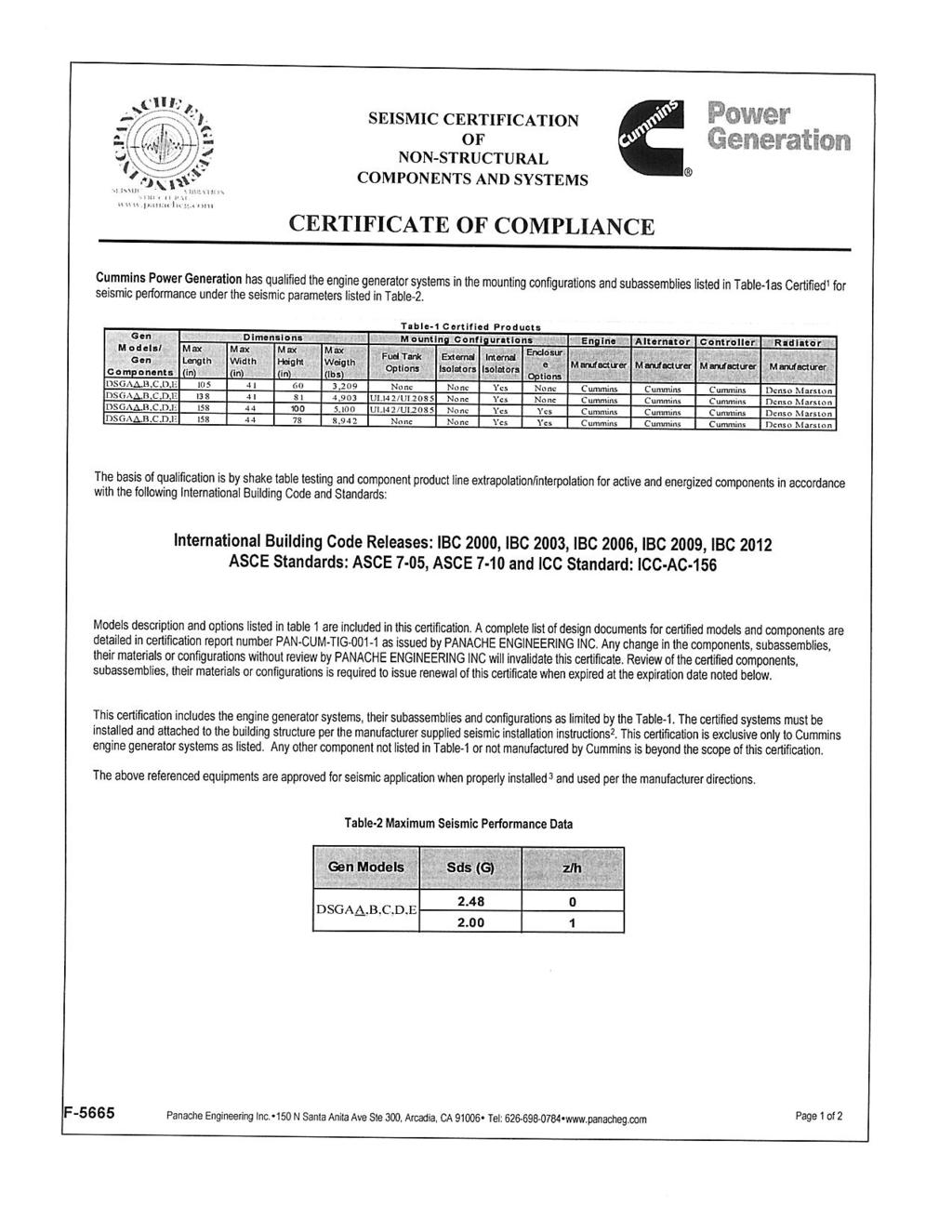
333
334
335 PROTOTYPE TEST SUPPORT (PTS) 60 HZ TEST SUMMARY GENERATOR SET MODELS REPRESENTATIVE PROTOTYPE 100 DSGAA 125 DSGAB Model: 200 DSGAE 150 DSGAC 175 DSGAD Alternator: UCDI274J 200 DSGAE Engine: QSB7-G5 NR3 The following summarizes prototype testing conducted on the designated representative prototype of the specified models. This testing is conducted to verify the complete generator set electrical and mechanical design integrity. Prototype testing is conducted only on generator sets not sold as new equipment. Maximum Surge Power: 213 kw Steady State Performance: The generator set was evaluated to determine the stated maximum surge power. The generator set was tested to verify steady state operating performance was within the specified maximum limits. Voltage Regulation: ±0.5% Random Voltage Variation: ±0.5% Frequency Regulation: Isochronous Random Frequency Variation: ±0.25% Torsional Analysis and Testing: The generator set was tested to verify that the design is not subjected to harmful torsional stresses. A spectrum analysis of the transducer output was conducted over the speed range of 1350 to 1950 RPM. Transient Performance: The generator set was tested with the alternator listed to verify single step loading capability as required by NFPA 110. Voltage and frequency response on load addition or rejection were evaluated. The following results were recorded: Cooling System: 50 C Ambient Full Load Acceptance: 0.50 in. H2O restriction Voltage Dip: 26.1 % The cooling system was tested to determine ambient temperature and static restriction capabilities. The test was performed at full rated load in elevated ambient temperature under stated static restriction conditions. Recovery Time: 2.9 Second Frequency Dip: 19.5 % Recovery Time: 3.9 Second Full Load Rejection: Voltage Rise: 22.5 % Durability: Recovery Time: 1.5 Second Frequency Rise: 9.1 % The generator set was subjected to a minimum 250 Recovery Time: 1.9 Second hour endurance test operating at variable load up to the standby rating based upon MIL-STD-705 to verify structural soundness and durability of the design. Electrical and Mechanical Strength: The generator set was tested to several single phase and three phase faults to verify that the generator can safely withstand the forces associated with short circuit conditions. The generator set was capable of producing full rated output at the conclusion of the testing. Harmonic Analysis: (per MIL-STD-705B, Method 601.4) Line to Line Line to Neutral Harmonic No Load Full Load No Load Full Load Cummins Power Generation Specification May Change Without Notice pts-285b
336 Drawing Name: A035C612 Revision: B Part Name: A035C611 Revision: B Sheet 1 of 6
337 Drawing Name: A035C612 Revision: B Part Name: A035C611 Revision: B Sheet 4 of 6
338 Drawing Name: A043V623 Revision: B Part Name: A043V622 Revision: B Sheet 1 of 2
339 Drawing Name: A029J531 Revision: F Part Name: A029J530 Revision: F Sheet 3 of 6
340 Drawing Name: A040K671 Revision: C Part Name: A040K670 Revision: C Sheet 1 of 4
341 Drawing Name: A040K671 Revision: C Part Name: A040K670 Revision: C Sheet 2 of 4
342 Drawing Name: A040K671 Revision: C Part Name: A040K670 Revision: C Sheet 3 of 4
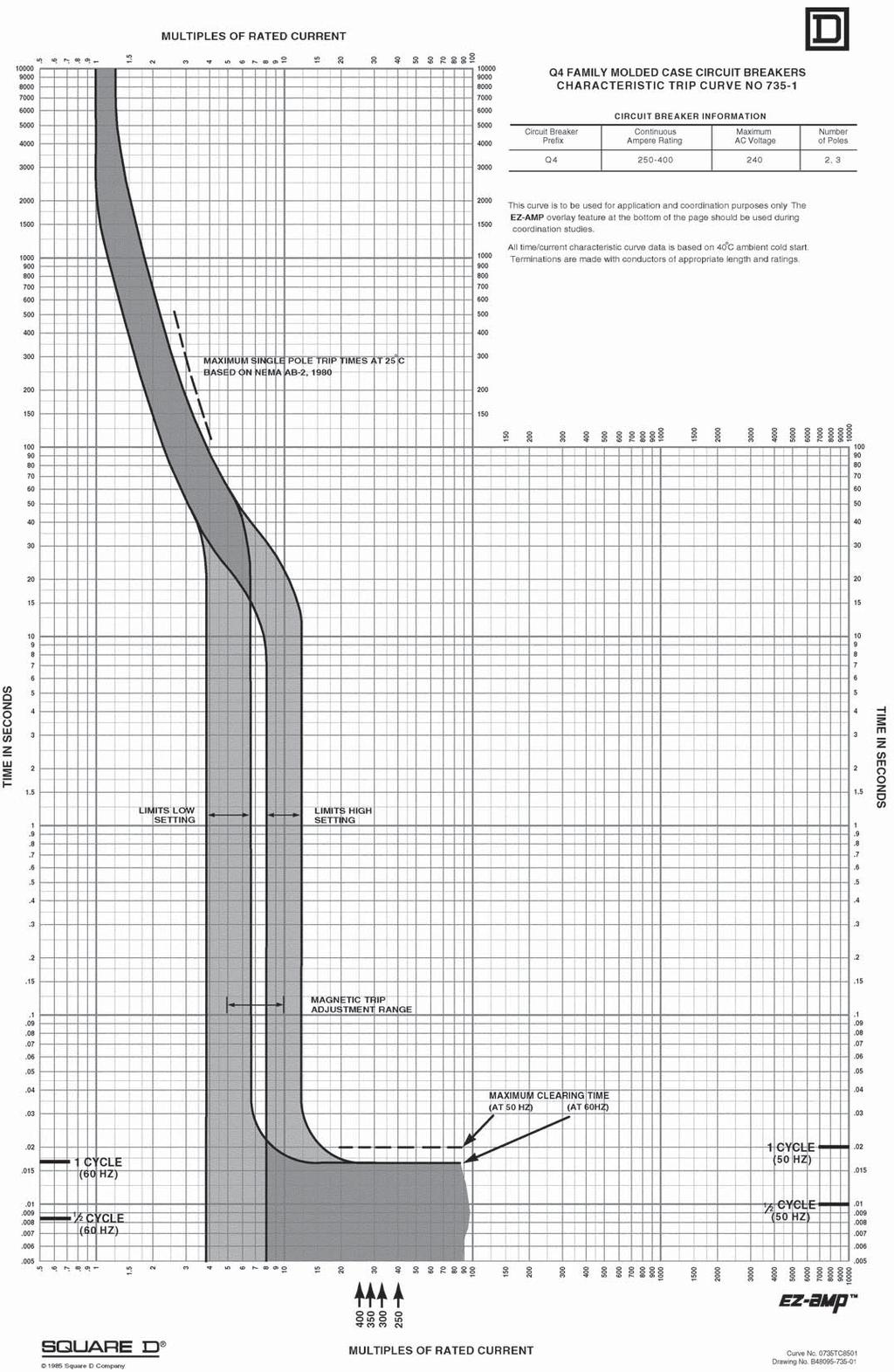
343
344 Drawing Name: A040K566 Revision: A Part Name: A040K565 Revision: A Sheet 1 of 2
345
346

347 Batteries and accessories Battery Specifications Cold cranking amps Ship weight lbs Part number Battery Voltage Reserve capacity Length Width Height Group size Dry D Dry C Wet C Wet Dry Dry D Wet Dry Wet Wet D Sealed NA 12 NA NP Dry D Sealed Wet XL Dry NF Qts electrolyte 2013 Cummins Power Generation Inc. All rights reserved. Cummins Power Generation and Cummins are registered trademarks of Cummins Inc. Our energy working for you. is a trademark of Cummins Power Generation. Specifications are subject to change without notice. AC-150m (2/13) Page 1 of 5

348 To be field installed within the NRG generator enclosure Intelligent Engine Start Battery Charger The Smart Choice for Mission-Critical Engine Starting Fast, accurate, mission-critical charging gives best starting reliability 4-rate, temperature-compensated output offers longest battery life Replace nearly any charger without planning ahead Industry-first battery-fault alarm helps dispatch service early Lasting reliability field MTBF > 1 million hours with industry-best warranty IBC seismic certification meets latest building codes, no installation delays S E C E R T I S M I F I C IBC I E D STORED ENERGY SYSTEMS
349 NRG Battery Charger Benefits and Features Failure to start due to battery problems is the leading cause of inoperable engine generator sets. SENS NRG battery charger maximizes starting system reliability while slashing genset servicing costs: One NRG replaces almost any charger without extra site visits. Installers can select or change at any time 120, 208 or 240 volts AC input, 12 or 24-volt battery and output settings optimized for nearly any lead-acid or nickel cadmium battery. Easy to understand user interface provides state-of-the-art system status including digital metering, NFPA 110 alarms and a battery fault alarm that can send service personnel to the site before failure to start. Batteries charged by NRG give higher performance and last longer. In uncontrolled environments precision charging by SENS increases battery life and watering intervals 400% or more. NRG meets all relevant industry standards including UL, NFPA 110 and CE. Seismic Certification per International Building Code (IBC) 2000, 2003, All units are C-UL listed. 50/60 Hz units add CE marking to UL agency marks. EnerGenius reliability technology built into every charger includes: and available 10-year complete warranty with reimbursement of field service costs Earn the best return on your charger investment choose SENS NRG

350 NRG Specifications AC Input Voltage Input current Frequency Input protection / VAC, +10%, single phase, field selectable 10A charger: 6.6/3.3 amps maximum 20A charger: 12.6/6.3 amps maximum 60 Hz +5% standard; 50/60 Hz +5% optional 1-pole fuse, soft-start, transient suppression Charger Output Nominal voltage ratings Optional voltage rating Battery settings Regulation Current Electronic current limit Charge characteristic Temperature compensation Output protection 12 or 24 volt nominal 12/24 volt, field selectable Six discrete battery voltage programs - Low or high S.G. flooded - Low or high S.G. VRLA - Nickel cadmium 9, 10, 18, 19 or 20 cells +0.5% (1/2%) line and load regulation 10 or 20 amps nominal 105% rated output typical no crank disconnect required Constant voltage, current limited, 4-rate automatic equalization Enable or disable anytime, remote sensor optional Current limit, 1-pole fuse, transient suppression Standard 4-rate charging User Interface, Indication and Alarms Digital meter Automatic meter alternately displays output volts, amps 4 Accuracy +2% volts, +5% amps Alarms LED and Form C contact(s) per table: Front panel status display 1. Alarms 1 available only on 10A charger 2. Form C contact provides summary alarm of these conditions. BBHH chargers include this alarm configuration. Contacts rated 30 VDC resistive 3. Battery fault alarm indicates these fault conditions: - Battery disconnected - Battery polarity reversed - Mismatched charger battery voltage - Open or high resistance charger to battery connection - Open battery cell or excessive internal resistance 4. Three-position jumper allows user to select from three display settings: alternating volts / amps (normal), constant volts, or constant amps
351 Controls AC input voltage select Optional 12/24-volt output select Battery program select Meter display select Fast charger enable/disable Temp compensation enable Remote temp comp enable Field-selectable switch Field-selectable two-position jumper Field-selectable six-position jumper Field-selectable three-position jumper Field-selectable two-position jumper Standard. Can be disabled or re-enabled in the field Connect optional remote sensor to temp comp port Simple field adjustments Environmental Operating temperature -20C to +60C, meets full specification to +45C Over temperature protection Gradual current reduction to maintain safe power device temperature Humidity 5% to 95%, non-condensing Vibration (10A unit) UL 991 Class B (2G sinusoidal) Transient immunity ANSI/IEEE C62.41, Cat. B, EN heavy industrial, EN Seismic Certification IBC 2000, 2003, 2006 Maximum S ds of 2.28 g Agency Standards Safety C-UL listed to UL 1236 (required for UL 2200 gensets), CSA standard 22.2 no M89 CE: 50/60 Hz units DOC to EN Agency marking 60 Hz: C-UL-US listed 50/60 Hz: C-UL-US listed plus CE marked EMC Emissions: FCC Part 15, Class B; EN Immunity: EN NFPA standards Optional agency compliance NFPA 70, NFPA 110. (NFPA 110 requires Alarms C ) Units with Alarms 1 configuration available with additional compliance to UL category BBHH and NFPA 20 Construction Housing/configuration Packaging Dimensions Printed circuit card Cooling Protection degree Damage prevention Electrical connections Material: Non-corroding aluminum. Configuration options: Open-frame and Slimline configurations only available in bulk OEM quantities and packaging See Drawings and Dimensions page for details Surface mount technology, conformal coated Natural convection Listed housing: NEMA-1 (IP20). Optional IP21 drip shield. Optional NEMA 3R enclosure Fully recessed display and controls Compression terminal blocks Warranty Standard warranty Optional warranty Three year parts and labor warranty (10 years magnetics and power semiconductors) from date of shipment If specified at time of order, warranty coverage can be increased to reimburse customer s documented field service costs up to the original charger price or increased to 5 or 10 years with field service cost reimbursement. Contact the factory for full details Optional features Input Input frequency, 50/60 Hz Remote temp comp sensor Recommended where battery and charger are in different locations Drip shield meets s/b (IP21) Protects from dripping water NEMA 3R housing Enables outdoor installation (remote temp sensor recommended) UL BBHH listing Available in 10A units with Alarms 1 Field service warranty Reimbursement of customer field service expenses up to charger price for 3, 5, or 10 years
352 Drawings and Dimensions 10A Chargers 20A Chargers
353 E All models offer field-selectable input 120/ volts. 60 Hz input is standard with C-UL listing. Optional 50/60 Hz input includes C-UL listing and adds CE mark. UL category code S: UL category BBGQ (standard) H: UL category BBHH (Alarms 1 only) Model Output voltage Output current 12: 12 volts 10: 10 amps 24: 24 volts 20: 20 amps 22: 12/24-volt field selectable AC input R: 120/ VAC, 60 Hz H: 120/ VAC, 50/60 Hz Alarm system code 1: LED and single Form C contact C: LEDs and Form C contacts to meet NFPA 110 Housing/Agency L: Enclosed: C-UL listed Contact SENS or your local sales representative for additional specification, engineering and installation information. Check the SENS web site for latest available data. Specification is subject to change without notice. S E I S M I C IBC 2000 C E R T I F I E D Contact Information For information and service on any SENS product, please contact us at: STORED ENERGY SYSTEMS
354 SENS EnerGenius Technical Manual 4. NEUTRAL CONNECTION The grounded circuit conductor (neutral) should be connected to the terminal marked N on the input terminal block, TB1. 5. WIRE RATINGS A. All conductors should be rated for use at 90º C or higher. B. All input and output conductor sizes should be coordinated with the fault protection devices: 10A on AC input (14 AWG, 2.5 mm 2 typical), 30A on DC output (10 AWG, 6.0 mm 2 typical). 1 A on Alarm terminal block (20 AWG, 0.5 mm 2 typical). C. Before installation, ensure adequate battery to charger wire gauge. Wire gauge that is too small may activate the open battery detector and the charger will shut down. The maximum allowed resistance seen by the charger is found in TABLE 1. These figures already include an allowance for charger variations (they are 80% of the typical trip-point) and are for the complete circuit: total of battery leads, battery's internal resistance, and any external equipment. The total resistance seen by the charger must not exceed the following values: TABLE 1 12V 24V Maximum Resistance 58m 116m D. To determine the appropriate cable and length, please refer to the following table: Wire Size Resistance per Foot TABLE 2 Maximum Charger to Battery Distance (Ft.) Recommended Charger to Battery Distance (Ft.) AWG mm 2 m/ft. 12V 24V 12V 24V The above lengths consider the resistance of the battery and cables only and do not take into account any additional interconnects. The above lengths are for operation at 25C. For high temperature installations (40C) reduce lengths by 10%. In the case of high resistance in the cables to the battery the charger may cycle between AC Fail and Battery Fault LEDs (approximately every 10 seconds). Cable runs exceeding the proper length for the cable gauge used most often cause this problem. The appropriate solution is to change the cable gauge to properly correspond with the necessary cable length (see TABLE 2). In some cases where the resistance is not too far above maximum, the charger may recover after some time (approximately 10 minutes) and start charging the batteries. If it is not possible to decrease the system resistance the Battery Fault feature can be disabled. Please contact SENS at for further information. E. Refer to local electrical codes for additional requirements. F. See Section 10 for Terminal Block wire ranges. 6. FUSE RATINGS A. CAUTION: For continued protection against risk of fire, replace only with same type and rating of fuse. B. DC Output Fuse SENS part number Bussman Type BK/ATC-30, or Littelfuse [ATO30], 30A, 32V, fast acting, blade type automotive C. AC Input Fuse SENS part number Bussman Type BK/AGC-10, 10A, 250VAC, fast acting, ferrule type cylindrical, ¼ X 1-¼ Service hotline:
 inputs or network inputs.")
355 PowerCommand Annunciator Discrete Input or PCCNet Description The Universal Annunciator Module provides visual and audible indication of up to 20 separate alarm or status conditions, based on discrete (relay) inputs or network inputs. Each LED can be controlled by either a discrete wire input or by a signal on the PCCNet network sent from an external device, such as a PCC1301 or PCC2100 (version 2.4 or later) control. In addition to the LEDs, the annunciator can control four custom relays based on signals received over the PCCNet. When one of the annunciator s discrete inputs is activated, the annunciator will broadcast that information over the network. By taking advantage of the network, discrete inputs and custom relays, the annunciator can be used as expanded I/O for a genset controller. Easily installed in a location to give immediate notification of an alarm or warning status. Designed to give operating/monitoring personnel quick-glance status information. The module directly senses battery voltage to provide green/yellow/red alarm and status information for that parameter. Genset controller complies with NFPA level two requirements when used with the display but without the annunciator panel. When used with the annunciator it meets NFPA level one requirements (emergency and standby power systems). The annunciator module can also be used for monitoring of transfer switch or other equipment status. Features Visual and audible warnings of up to 20 separate alarm or status conditions. LEDs can be controlled either via PCCNet or discrete input. Status of discrete inputs is broadcast on network. Four custom relays can be controlled over the PCCNet network. Configurable LED color (red, yellow or green) and selectable horn operation allows maximum flexibility. Standard NFPA 110 label, field configurable for other alarm status and conditions. Each audible alarm is annunciated, regardless of the number of existing alarm conditions displayed. Sealed membrane panel design provides environmental protection for internal components and is easy to clean. Configurable for negative (ground) input or positive input. Integral DC voltage sensing. Flush or surface mount provisions. UL Listed and labeled; CSA certified; CE marked Cummins Power Generation Inc. All rights reserved. Cummins Power Generationand Cummins are registered trademarks of Cummins Inc. PowerCommand and Our energy working for you. are trademarks of Cummins Power Generation. Other company, product, or service names may be trademarks or service marks of others. Specifications are subject to change without notice. S-1472e (8/09)
356 Specifications Signal requirements Positive - Input impedance is 1.82 kohms to ground; maximum input voltage = 31 VDC. Negative - Input impedance is 1.82 kohms to Bat+: inputs are at Bat+ level when open. Sink/source current threshold for detection ua minimum, 3 ma maximum. Typical conductor size: 16 ga for m (1000 ft) Max conductor size for terminal: 12 ga Relay outputs 0.2 A at 125 VAC and 1 A at 30 VDC Network connections Use Belden 9729 two pair, stranded, shielded 24 AWG twisted pair cable for all PCCNet connections. Total network length can not exceed 1219 m (4000 ft). Up to 20 nodes can be connected to the network. Note: Any communications wire connected to the generator set should be stranded cable. Power Maximum consumption: 15 watts Battery voltage Functional range - Audible and visual conditions operational from 6.5 to 31 VDC. Low voltage setting VDC for 12 Volt nominal systems; 24.0 for 24 Volt nominal systems. High voltage setting Volt for 12 Volt nominal systems; 32.0 Volt for 24 Volt nominal systems. Alarm horn Sound level: 90 db at 30 cm Physical Weight (with enclosure): 1.4 kg (3.0 lbs) Temperature -20C to +70 C (-4 F to +158 F) Humidity 10% to 95% RH (non-condensing) Default lamp configurations Can be configured for current NFPA 110 standard or as a replacement for Legacy (pre-2001) NFPA 110 annunciator ( or ) NFPA 110 Lamp Description Color Horn Flash DS1 Customer fault 1 Green No No DS2 Customer fault 2 Amber No No DS3 Customer fault 3 Red No No DS4 Genset supplying load Amber No No DS5 Charger AC failure Amber Yes No DS6 Low coolant level Amber Yes No DS7 Low fuel level Red Yes No DS8 Check generator set Amber No No DS9 Not in auto Red Yes Yes DS10 Generator set running Amber No No DS11 High battery voltage Amber Yes No DS12 Low battery voltage Red Yes No DS13 Weak battery Red Yes No DS14 Fail to start Red Yes No DS15 Low coolant temp Red Yes No DS16 Pre-high engine temp Amber Yes No DS17 High engine temp Red Yes No DS18 Pre-low oil pressure Red Yes No DS19 Low oil pressure Red Yes No DS20 Overspeed Red Yes No Our energy working for you Cummins Power Generation Inc. All rights reserved. Cummins Power Generationand Cummins are registered trademarks of Cummins Inc. PowerCommand and Our energy working for you. are trademarks of Cummins Power Generation. Other company, product, or service names may be trademarks or service marks of others. Specifications are subject to change without notice. S-1472e (8/09)
357 Typical installation Our energy working for you Cummins Power Generation Inc. All rights reserved. Cummins Power Generationand Cummins are registered trademarks of Cummins Inc. PowerCommand and Our energy working for you. are trademarks of Cummins Power Generation. Other company, product, or service names may be trademarks or service marks of others. Specifications are subject to change without notice. S-1472e (8/09)
 Ordering information Dimensions: in (mm) Part number Description 0300-5929-01 Panel mount 0300-5929-02 Panel with enclosure See your distributor for more information.")
358 Dimensions 3.00" (76mm) 5.25" (133mm) 3.50" (88.9mm) 6.25" (159mm) 0.219" (5.6mm) MOUNTING HOLES 4.50" (114mm) Ordering information Dimensions: in (mm) Part number Description Panel mount Panel with enclosure See your distributor for more information. Cummins Power Generation Americas rd Avenue N.E. Minneapolis, MN USA Phone: Fax: Europe, CIS, Middle East and Africa Manston Park Columbus Ave. Manston Ramsgate Kent CT 12 5BF United Kingdom Phone Fax Asia Pacific 10 Toh Guan Road #07-01 TT International Tradepark Singapore Phone Fax Our energy working for you Cummins Power Generation Inc. All rights reserved. Cummins Power Generationand Cummins are registered trademarks of Cummins Inc. PowerCommand and Our energy working for you. are trademarks of Cummins Power Generation. Other company, product, or service names may be trademarks or service marks of others. Specifications are subject to change without notice. S-1472e (8/09)

359 Preventative Maintenance Kits kw Generator sets Description Features Cummins Power Generation Preventative Maintenance kits include our state-of-the-art technology in oil, fuel, and air filtration. These components meet or exceed specifications for maximum quality and performance. We custom-design high end systems for engine lubricating oil, fuel, and air filtering. These performance-tested systems feature a variety of media with particle retention capabilities to micrometer filtration that enhance protection without sacrificing quality. CPG provides the filtration products that you need to protect and maintain modern engines. Oil - Lube oil is an essential to life of your engine. lt lubricates, and protects engine components. Since contaminants enter the lube system due to engine wear, it is vital that you use the best quality oil filtration. Fuel - With filtration requirements as low as 2 microns on some high pressure common rail (HPCR) fuel systems, and new fuels like ultra low sulfur diesel, it is imperative that you have the best quality fuel filtration. Air - Clean air is essential to the performance and longevity of any internal combustion engine. With increasingly stricter levels of emissions having to be met, it s imperative that you use the best quality air filtration. Coolant - Fully formulated coolants contain specific amounts of glycol, de-ionized water, and coolant additives. Over time contaminants enter the cooling system making it imperative to use the best quality coolant filtration. 250 Hours or 6 months run time Increased uptime Enhanced fuel economy Lower Operating costs Environmental safety Reliability and durability Highest performance Optimized performance Convenience of ordering with generator Prolonged engine life Reduced maintenance costs 2012 Cummins Power Generation Inc. All rights reserved. Cummins Power Generation and Cummins are registered trademarks of Cummins Inc. Our energy working for you. is a trademark of Cummins Power Generation. Specifications are subject to change without notice. NAAC-5489b-EN (11/12)
360 Genset Model Engine Model PM Kit Part Number Normal Duty Air Cleaner PM Kit Part Number Heavy Duty Air Cleaner DFE's QSX15L-G9 NR2 A041C902 A041C904 DFH's QST30-G1 A041D162 A041D167 DFLC KTA50-G3 A041D198 NA DFLE KTA50-G9 A041D205 A041D221 DGB's 4B3.9-G2 A041C225 NA DGC s 4BT3.9-G4 NA A041C669 DGCG 4BTA3.9-G3 A041C671 NA DGDB 6BT5.9-G6 A041C772 NA DGDK 6BTA5.9-G3 A041C775 NA DGFA/B 6CTA8.3-G2 A041C806 NA DGFC/S 6CTAA8.3-G2 NA A041C806 DGH s 4BT3.3-G5/G7 A044C436 NA DKA s F2803-E2BG A041B930 NA DQC's QSK23-G3/G7 NR2 A041D139 A041D143 DQDA's QSL9-G3 A041C870 A041C874 DQFA's QST30-G5 NR2 A041D169 A041D187 DQGA s QSK50-G4 NR2 A041D225 NA DQGAC QSK50-DR (Oil & Gas) NA A041D335 DQHA's QSM11-G4 NR3 A041C889 A041C891 DQKAA/B QSK60-G6 (A034D142) A041D324 NA DQKAA/B QSK60-G6 ( ) NA NA DQKAD/E/F QSK60-G6/G14 NA NA DQKB/C QSK60-G3 (hi cap oil) A041D318 NA DQKB/C/D/H QSK60-G4/G6/G8 A041D316 NA DQKH QSK60-G9 A041D322 NA DQLD QSK78-G8 NR1 A042W151 A041D331 DQLE/F QSK78-G11/12 A042W151 A042W153 DFLK KTA50-DR (Oil & Gas) NA A041D344 DQMAA QSK19-G3 NR2 A041C934 A041C936 DSFA's QSB5-G3 A041C704 NA DSGAA QSB7-G3/G5 NR3 NA A041C792 DSHA's QSL9-G2 A041C870 A041C874 DSKAA/AB/BA D1703-M-E3BG NA A041B934 DSKCA V3300-E3BG NA A041B936 GGHE/F WSG A A041B979 A041B983 GGHG/H WSG A A041B987 NA GGL's GM 8.1L V8 Turbo A041C802 NA GGM's GM 3.0L (HO) A041B943 A041B947 GGP's GM 5.0L A041B957 A041B Cummins Power Generation Inc. All rights reserved. Cummins Power Generation and Cummins are registered trademarks of Cummins Inc. Our energy working for you. is a trademark of Cummins Power Generation. Specifications are subject to change without notice. NAAC-5489b-EN (11/12)
361 Limited Standby 5 Year or 1,500 hour Comprehensive Extended Warranty L031 Commercial Generating Set When purchased, this limited extended warranty applies to Cummins Power Generation branded commercial generating sets and associated accessories (hereinafter referred to as "Product"). This warranty covers any failures of the Product, under normal use and service, which result from a defect in material or factory workmanship. Warranty Period: The warranty start date is the date of initial start up, first rental, demonstration or 18 months after factory ship date, whichever is sooner. The coverage duration is 5 years from warranty start date or 1,500 hours or whichever occurs first. Emergency Standby Power (ESP) is defined as the maximum power available during a variable electrical power sequence, under the stated operating conditions, for which a generating set is capable of delivering in the event of a utility power outage. The permissible average power output over 24 hours of operation shall not exceed 70% of the ESP. Cummins Power Generation Responsibilities: In the event of a failure of the Product during the extended warranty period due to defects in material or workmanship, Cummins Power Generation will only be responsible for the following costs: All parts and labor required to repair the Product. Reasonable travel expenses to and from the Product site location. Maintenance items that are contaminated or damaged by a warrantable failure. Owner Responsibilities: The owner will be responsible for the following: Notifying Cummins Power Generation distributor or dealer within 30 days of the discovery of failure. Installing, operating, commissioning and maintaining the Product in accordance with Cummins Power Generation s published policies and guidelines. Providing evidence for date of commissioning. Providing sufficient access to and reasonable ability to remove the Product from the installation in the event of a warrantable failure. In addition, the owner will be responsible for: Incremental costs and expenses associated with Product removal and reinstallation resulting from non-standard installations. Costs associated with rental of generating sets used to replace the Product being repaired. Costs associated with labor overtime and premium shipping requested by the owner. All downtime expenses, fines, all applicable taxes, and other losses resulting from a warrantable failure. Limitations: This limited extended warranty does not cover Product failures resulting from: Inappropriate use relative to designated power rating. Inappropriate use relative to application guidelines. Normal wear and tear. Improper and/or unauthorized installation. Owner s or operator s negligence, accidents or misuse. Lack of maintenance or unauthorized repair. Noncompliance with any Cummins Power Generation published guideline or policy. Use of improper or contaminated fuels, coolants or lubricants. Improper storage before and after commissioning. Owner s delay in making Product available after notification of potential Product problem. Effective Date: 01-October-2009 Page 1 of 2
362 Use of steel enclosures within 60 miles of the coast of salt water when aluminum or an alternate non-corrosive material enclosure option is available. Replacement parts and accessories not authorized by Cummins Power Generation. Use of Battle Short Mode. Owner or operator abuse or neglect such as: operation without adequate coolant or lubricants; overfueling; overspeeding; lack of maintenance to lubricating, cooling or air intake systems; late servicing and maintenance; improper storage, starting, warm-up, run-in or shutdown practices, or for progressive damage resulting from a defective shutdown or warning device. Damage to parts, fixtures, housings, attachments and accessory items that are not part of the generating set. This limited extended warranty does not cover costs resulting from: Difficulty in gaining access to the Product. Repair of cosmetic damage to enclosures. Items not covered by this limited extended warranty: Batteries Enclosures Coolant heating elements Maintenance items Aftertreatment component failures. CUMMINS POWER GENERATION RIGHT TO FAILED COMPONENTS: Failed components claimed under warranty remain the property of Cummins Power Generation. Cummins Power Generation has the right to reclaim any failed component that has been replaced under warranty. THE WARRANTIES SET FORTH HEREIN ARE THE SOLE WARRANTIES MADE BY CUMMINS POWER GENERATION IN REGARD TO THE PRODUCT. CUMMINS POWER GENERATION MAKES NO OTHER WARRANTIES, EXPRESS OR IMPLIED, OR OF MERCHANTABILITY OR FITNESS FOR A PARTICULAR PURPOSE. IN NO EVENT IS CUMMINS POWER GENERATION LIABLE FOR INCIDENTAL OR CONSEQUENTIAL DAMAGES. This limited extended warranty shall be enforced to the maximum extent permitted by applicable law. This limited extended warranty gives the owner specific rights that may vary from state to state or from jurisdiction to jurisdiction. Product Model Number: Product Serial Number: Date in Service: Effective Date: 01-October-2009 Page 2 of 2
363 OTPC transfer switch open and closed transition Amp Description OTPC transfer switches are designed for operation and switching of electrical loads between primary power and standby generator sets. They are suitable for use in emergency, legally required and optional standby applications. The switch monitors both power sources, signals generator set startup, automatically transfers power, and returns the load to the primary power source when the utility returns and stabilizes. OTPC transfer switches are available with closed transition transfer. By briefly connecting the two sources (for 100 msec or less), the transfer from the alternate source back to the normal source occurs without interruption in the power supply to loads. NEC All switches are UL 1008 Listed with UL Type Rated cabinets and UL Listed CU-AL terminals. All switches are certified to CSA 282 Emergency Electrical Power Supply for Buildings, up to 600 VAC. Suitable for use in emergency, legally required and standby applications per NEC 700, 701 and 702. All switches comply with NFPA 70, 99 and 110 (Level 1). All switches comply with NEMA ICS 10. All switches comply with IEEE 446 Recommended Practice for Emergency and Standby Power Systems. This transfer switch is designed and manufactured in facilities certified to ISO9001. Features PowerCommand control - A fully featured microprocessor-based control with digital display. Controls allow operator to enter settings and make adjustments to software-enabled features easily and accurately. Accommodates up to eight event schedules. Programmed transition Open transition timing can be adjusted to completely disconnect the load from both sources for a programmed time period, as recommended by NEMA MG-1 for transfer of inductive loads. Advanced transfer switch mechanism Unique bidirectional linear actuator provides smooth, continuous transfer switch action during automatic operation. Robust control system design - Optically isolated logic inputs and isolation transformers for AC power inputs provide high-voltage surge protection. Main contacts - Heavy-duty silver alloy contacts with multi-leaf arc chutes are rated for 100% load interruption. They require no routine contact maintenance and provide 100% continuous current ratings. Communications capability - The transfer switch is capable of communicating with other transfer switches, SCADA and remote monitoring systems, or Cummins Power Generation generators utilizing LonWorks protocol. Easy service/access - Single-plug harness connection and compatible terminal markings simplify servicing. Access space is ample. Door-mounted controls are field-programmable; no tool is required. Complete product line - Cummins Power Generation offers a wide range of equipment, accessories and services to suit virtually any backup power application. Warranty and service - Products are backed by a comprehensive warranty and a worldwide network of distributors with factory-trained service technicians Cummins Power Generation Inc. All rights reserved. Cummins Power Generation and Cummins are registered trademarks of Cummins Inc. PowerCommand and Our energy working for you. are trademarks of Cummins Power Generation. Other company, product, or service names may be trademarks or service marks of others. Specifications are subject to change without notice. S-1270ad (5/12)

364 Transfer switch mechanism Specifications Voltage rating Arc interruption Neutral bar Auxiliary contacts Our energy working for you. Transfer switch mechanism is electrically operated and mechanically held in the Source 1 and Source 2 positions. The transfer switch incorporates electrical and mechanical interlocks to prevent inadvertent interconnection of the sources. Independent break-before-make action is used for both 3-pole and 4-pole/ switched neutral switches. This design allows use of sync check operation when required, or control of the operating speed of the transfer switch for proper transfer of motor and rectifier-based loads (programmed transition feature). True 4-pole switching allows for proper ground (earth) fault sensing and consistent, reliable operation for the life of the transfer switch. The neutral poles of the transfer switch have the same ratings as the phase poles and are operated by a common crossbar mechanism, eliminating the possibility of incorrect neutral operation at any point in the operating cycle, or due to failure of a neutral operator. High pressure silver alloy contacts resist burning and pitting. Separate arcing surfaces further protect the main contacts. Contact wear is reduced by multiple leaf arc chutes that cool and quench the arcs. Barriers separate the phases to prevent interphase flashover. A transparent protective cover allows visual inspection while inhibiting inadvertent contact with energized components. Switch mechanism, including contact assemblies, is third party certified to verify suitability for applications requiring high endurance switching capability for the life of the transfer switch. Withstand and closing ratings are validated using the same set of contacts, further demonstrating the robust nature of the design. 600 VAC, 50 or 60 Hz. Multiple leaf arc chutes provide dependable arc interruption. Operating temperature -40 F (-40 C) to 140 F (60 C) Storage temperature -40 F (-40 C) to 140 F (60 C) Humidity Altitude Surge withstand ratings Total transfer time (sourceto-source) Manual operation handles A full current-rated neutral bar with lugs is standard on enclosed 3-pole transfer switches. Two isolated contacts (one for each source) indicating switch position are provided for customer use. Contacts are normally open, and close to indicate connection to the source. Wired to terminal block for easy access. Rated at 10 amps continuous and 250 VAC maximum. UL recognized, and CSA-certified. Up to 95% relative, non-condensing Up to 10,000 ft (3,000 m) without derating Voltage surge performance and testing in compliance with the requirements of IEEE C62.41 (Category B3) and IEEE C Will not exceed 6 cycles at 60 Hz with normal voltage applied to the actuator and without programmed transition enabled. Transfer switches rated through 1000 amps are equipped with permanently attached operating handles and quick-break, quick-make contact mechanisms suitable for manual operation. Transfer switches over 1000 amps are equipped with manual operators. All switches must be de-energized before manual operation is attempted. Transition modes Open transition/programmed: Controls the time required for the device to switch from source to source, so that the load-generated voltages decay to a safe level before connecting to an energized source. Recommended by NEMA MG- 1 to prevent nuisance-tripping breakers and load damage. Adjustable 0-60 seconds, default 0 seconds. Programmed transition is standard on amp switches, and optional on amps. Open transition/in-phase: Initiates open transition transfer when in-phase monitor senses both sources are in phase. Operates in a break-before-make sequence. Includes ability to enable programmed transition as a back-up. If sources are not in phase within 120 seconds, switches from amps will transfer using programmed transition (not available on open transition switches over 1200 amps). Closed transition: Used in applications where loads are sensitive to the momentary power interruption that occurs when performing open transition between sources. Closed transition is accomplished by briefly (<100 msec) paralleling two good sources to eliminate the momentary break in the power supply. Closed transition is only available as an option on OTPC models from amps. Genset-to-genset: Either genset can be designated as the lead genset. If the lead genset goes down or is taken offline, the transfer switch starts the second genset and transfers the load. The control can be programmed to alternate between the two gensets at a set interval up to 336 hours (2 weeks) Cummins Power Generation Inc. All rights reserved. Cummins Power Generation and Cummins are registered trademarks of Cummins Inc. PowerCommand and Our energy working for you. are trademarks of Cummins Power Generation. Other company, product, or service names may be trademarks or service marks of others. Specifications are subject to change without notice. S-1270ad (5/12)
365 PowerCommand control PowerCommand controls are microprocessor based and developed specifically for automatic transfer switch operation. The control includes all of the features and options required for most applications. LED lamps indicate source availability, source connected, exercise mode and test mode. Flash memory stores the control settings. Contents of the memory are not lost even if power to the controller is lost. On-board battery maintains the real-time clock setting and the engine start time delay. Choice of two control packages allows selection of the most suitable control for the application. Control functions Level 1 control (C023) Level 2 control (C024) Open transition (in-phase) Open transition (in-phase) Open transition (programmed) Open transition (programmed) Utility-to-genset applications Closed transition (includes fail-to-disconnect timer to prevent Software adjustable time delays: extended paralleling with the utility) Engine start: 0 to 120 sec Utility-to-genset applications Transfer normal to emergency: 0 to 120 sec Utility-to-utility applications Re-transfer emergency to normal: 0 to 30 min Genset-to-genset applications Engine stop: 0 to 30 min Software adjustable time delays: Programmed transition: 0 to 60 sec Engine start: 0 to 120 sec Undervoltage sensing: 3-phase normal, 1-phase emergency Transfer normal to emergency: 0 to 120 sec Accuracy: =/- 2% Re-transfer emergency to normal: 0 to 30 min Pickup: 85% to 100% of nominal voltage Engine stop: 0 to 30 min Dropout: 75% to 98% of pickup setting Programmed transition: 0 to 60 sec Dropout time delay: 0-4 sec Undervoltage sensing: 3-phase normal, 3-phase emergency Overvoltage sensing: 3-phase normal, 1-phase emergency Accuracy: +/- 2% Accuracy: =/- 2% Pickup: 85% to 100% of nominal voltage Pickup: 95% to 99% of dropout setting Dropout: 75% to 98% of pickup setting Dropout: 105% to 135% of nominal voltage Dropout time delay: 0-4 sec Dropout time delay: 0 to 120 sec Overvoltage sensing: 3-phase normal, 3-phase emergency Over/under frequency sensing: Accuracy: ±2% Accuracy: ±0.05 Hz Pickup: 95% to 99% of dropout setting Pickup: ±5% to ±20% of nominal frequency Dropout: 105% to 135% of nominal voltage Dropout: 1-5% beyond pickup Dropout time delay: 0 to 120 sec Dropout time delay: 0.1 to 15.0 sec Over/under frequency sensing: Programmable genset exerciser: One event/schedule with or Accuracy: =/ Hz w/o load Pickup: ±5% to ±20% of nominal frequency Basic indicator panel: Dropout: 1-5% beyond pickup Source available/connected LED indicators Dropout time delay: 0.1 to 15.0 sec Test/exercise/override buttons Voltage imbalance sensing: Digital display optional (M018) Dropout: 2% to 10% Analog bar graph meter display optional (D009) Pickup: 90% of dropout Date/time-stamped event recording: 50 events Time delay: 2.0 to 20.0 sec Load sequencing: Optional with network communications Phase rotation sensing: module M031. Provides control for eight steps of load with an Time delay: 100 msec adjustable time delay for each step on transfer, re-transfer or Loss of single phase detection: both. Time delay: 100 msec Programmable genset exerciser: Eight events/schedules with or w/o load Basic indicator panel: Source available/connected LED indicators Test/exercise/override buttons Digital display standard Analog bar graph meter display optional (D009) Date/time-stamped event recording: 50 events Load sequencing: Optional with network communications module M031. Provides control for eight steps of load with an adjustable time delay for each step on transfer, re-transfer, or both. Genset-to-genset: Same functions as above, for lead and secondary generators. Utility-to-utility: Same functions as above, for preferred and alternate source. Our energy working for you Cummins Power Generation Inc. All rights reserved. Cummins Power Generation and Cummins are registered trademarks of Cummins Inc. PowerCommand and Our energy working for you. are trademarks of Cummins Power Generation. Other company, product, or service names may be trademarks or service marks of others. Specifications are subject to change without notice. S-1270ad (5/12)
366 Time-delay functions Engine start: Prevents nuisance genset starts due to momentary power system variation or loss. Not included in utility-to-utility systems. Transfer normal to emergency: Allows genset to stabilize before application of load. Prevents power interruption if normal source variation or loss is momentary. Allows staggered transfer of loads in multiple transfer switch systems. For genset-to-genset applications, delays transfer of load from lead to secondary generator. Re-transfer emergency to normal: Allows the utility to stabilize before re-transfer of load. Prevents needless power interruption if return of normal source is momentary. Allows staggered transfer of loads in multiple transfer switch systems. For genset-to-genset applications, delays re-transfer of load from secondary back to lead generator. Engine stop: Maintains availability of the genset for immediate reconnection if the normal source fails shortly after retransfer. Allows gradual genset cool down by running unloaded. Not included in utility-to-utility systems. Elevator pre-transfer signal: Requires optional relay signal module (M023). Signals elevator system that transfer is pending and delays transfer for pre-set interval of 0-60 seconds to prevent a power interruption during elevator operation. User interfaces Basic interface panel LED indicators provide at-a-glance source and transfer switch status for quick summary of system conditions. Test and override buttons allow delays to be bypassed for rapid system checkout. Digital display (M018) The digital display provides a convenient method for monitoring load power conditions, adjusting transfer switch parameters, monitoring PowerCommand network status or reviewing transfer switch events. Password protection limits access to adjustments to authorized personnel. The digital display is optional with the PowerCommand Level 1 control and comes standard with the Level 2 control. User interface options Front panel security key (M017) Locks front panel to prohibit access to digital control settings. Prevents unauthorized activation of transfer or test functions. Bar graph meter display (D009) An LED bar graph display provides an easy-to-read indicator of the level of power being supplied to the load. Information displayed includes: 3-phase voltage and current, frequency, power factor, and kilowatts. Green, amber, and red LEDs provide at-a-glance indication of system acceptability. Available as an option with the Level 2 PowerCommand microprocessor control. Control options Relay signal module (M023) Provides relay output contacts for sending information to the building monitoring and control system. Relay outputs include: Source 1 connected/available, Source 2 connected/available, not in auto, test/exercise active, failed to disconnect, failed to synchronize, failed to transfer/re-transfer, and elevator control pre-transfer signal. Loadshed (M007) Removes the load from the emergency power source by driving the transfer switch to the neutral position when signaled remotely. Transfers load back to the emergency source when the signal contacts open. Immediately retransfers back to the primary source when available. Available for utility-to-genset applications only. PowerCommand network interface (M031) Provides connection to the PowerCommand network. LonWorks compatible for integration with building monitoring and control system. Load power and load current monitoring (M022) Measures load phase and neutral current, power factor, real power (kw) and apparent power (kva). Warns of excessive neutral current resulting from unbalanced or nonlinear loads. Minimum current level detection is 3% Cummins Power Generation Inc. All rights reserved. Cummins Power Generation and Cummins are registered trademarks of Cummins Inc. PowerCommand and Our energy working for you. are trademarks of Cummins Power Generation. Other company, product, or service names may be trademarks or service marks of others. Specifications are subject to change without notice. S-1270ad (5/12)
367 UL withstand and closing ratings OTPC transfer switches must be protected by circuit breakers or fuses. Referenced drawings include detailed listings of specific breakers or fuse types that must be used with the respective transfer switches. Consult with your distributor/dealer to obtain the necessary drawings. Withstand and closing ratings (WCR) are stated in symmetrical RMS amperes. Transfer switch ampere 40, 70, pole 40, 70, pole 150, 225, , 400, , 1000 open 1000, 1200 closed 1200 open 1600, Fuse protection MCCB protection Special circuit breaker protection volts max with specific With specific manufacturers Max MCCB Drawing current limiting Max CLB MCCBs rating reference breakers (CLB) rating Drawing reference 14,000 at ,000 at A ,000 at ,000 at A ,000 at ,000 at A ,000 at ,000 at A ,000 at ,000 at A ,000 at ,000 at A ,000 at ,000 at A ,000 at ,000 at A ,000 at ,000 at A ,000 at ,000 at A ,000 at ,000 at A ,000 at 600* 65,000 at A ,000 at ,000 at A A030U183 65,000 at ,000 at A A030U ,000 at ,000 at A ,000 at 600* 85,000 at A ,000 at ,000 at A ,000 at 600* 85,000 at A ,000 at ,000 at 600* 5000 A ,000 at A volts max. with Transfer switch ampere current limiting fuses Max fuse, size and type Drawing reference 40, 70, ,000 at and 4-pole 200,000 at A Class, J, RK1, RK5, T , 225, ,000 at A Class, J, RK1, RK5 200,000 at A Class L or T , 400, ,000 at A Class, RK1 or RK5 200,000 at A Class L or T ,000 at A Class, J, RK1 or RK5 800, 1000 open 1200 A Class T ,000 at A Class L 1000, 1200 closed 200,000 at ,000 at 600* 3000 A Class L open 200,000 at ,000 at 600* 3000 A Class L A030U , ,000 at ,000 at 600* 2500 A Class L ,000 at ,000 at 600* 4000 A Class L ,000 at ,000 at 600* 6000 A Class L * CSA only Our energy working for you Cummins Power Generation Inc. All rights reserved. Cummins Power Generation and Cummins are registered trademarks of Cummins Inc. PowerCommand and Our energy working for you. are trademarks of Cummins Power Generation. Other company, product, or service names may be trademarks or service marks of others. Specifications are subject to change without notice. S-1270ad (5/12)
368 3-cycle ratings Transfer switch ampere 1000, 1200 closed 1200 open 1600, volts max 3-cycle rating Max MCCB rating Drawing reference 50,000 at ,000 at 600* 1600 A ,000 at ,000 at 600* 1600 A A030U ,000 at ,000 at 600* 4000 A ,000 at ,000 at 600* 4000 A ,000 at ,000 at 600* 5000 A * CSA only Transfer switch lug capacities All lugs accept copper or aluminum wire unless indicated otherwise. Cables per Amp rating phase Size 40, 70, pole 1 #12 AWG-2/ pole 1 #14 AWG-2/0 70, pole 1 #6 AWG MCM 150, #6 AWG MCM #6 AWG MCM 1 3/0-600 MCM 300, or 2 3/0-250 MCM MCM 800, 1000 open MCM 1000, 1200 closed 4 #2 AWG to 600 MCM 1200 open 4 #2AWG to 750 MCM 1600, #2 AWG to 600 MCM (lugs optional) #2 AWG to 750 MCM (lugs optional) /0 AWG to 750 MCM (lugs optional) Our energy working for you Cummins Power Generation Inc. All rights reserved. Cummins Power Generation and Cummins are registered trademarks of Cummins Inc. PowerCommand and Our energy working for you. are trademarks of Cummins Power Generation. Other company, product, or service names may be trademarks or service marks of others. Specifications are subject to change without notice. S-1270ad (5/12)
369 Enclosures The transfer switch and control are mounted in a key-locking enclosure. Switches from amps are wall-mounted. Switches from amps are floor-mounted. Wire bend space complies with 2009 NEC. Dimensions - transfer switch in UL type 1 enclosure Depth Amp rating Height Width Door closed Door open Weight Outline drawing in mm in mm in mm in mm lb kg 40, 70, pole , 70, pole , , 400, , 1000 open , 1200 closed open A030L , 2000* * * Dimensions - transfer switch in UL type 3R, 4 or 12 enclosure Depth Cabinet Outline Amp rating Height Width Door closed Door open Weight type drawing in mm in mm in mm in mm lb kg 3R, , 70, pole R, , 70, pole R, , R, R, , 400, R, , 1000 open , 1200 closed R, 12, R, 12 A030L open A041N , 2000* R, 12, * R * R Dimensions - transfer switch in UL type 4X stainless steel enclosure Depth Cabinet Outline Amp rating Height Width Door closed Door open Weight type drawing in mm in mm in mm in mm lb kg 40, 70, pole X , 70, pole X , X X , 400, X , 1000 open X , 1200 closed X open X A041N , X * Rear and side access is required for installation. Dimensions shown are for 4-pole. For information on 3-pole switches, call factory Cummins Power Generation Inc. All rights reserved. Cummins Power Generation and Cummins are registered trademarks of Cummins Inc. PowerCommand and Our energy working for you. are trademarks of Cummins Power Generation. Other company, product, or service names may be trademarks or service marks of others. Specifications are subject to change without notice. S-1270ad (5/12)
370 Submittal detail Amperage ratings Voltage ratings R * R R R R R R R R R * Single phase connection (not available on amps) Pole configuration A028 Poles - 3 (solid neutral) A029 Poles - 4 (switched neutral) Frequency A Hertz A Hertz Transfer mode A077 Open transition/in-phase A078 Open transition/programmed A079 Closed transition (available amps, for closed transition below 1000 amps, see CHPC spec sheet S-1437) Application A035 Utility to genset A036 Utility to utility A037 Genset to genset System options A041 Single Phase, 2-wire or 3-wire (not available amps) A042 Three Phase, 3-wire or 4-wire Enclosure B001 Type 1: Indoor use, provides some protection against dirt (similar to IEC type IP30) B002 Type 3R:Intended for outdoor use, provides some protection from dirt, rain and snow (similar to IEC type IP34) B003 Type 4: Indoor or outdoor use, provides some protection from wind-blown dust and water spray (similar to IEC type IP65) B004 Open Construction: No enclosure - includes automatic transfer switch and controls (call factory for dimensions) B010 Type 12: Indoor use, some protection from dust (similar to IEC type IP61) B025 Type 4X: Stainless steel, indoor or outdoor use, provides some protection from corrosion (similar to IEC Type IP65) Cummins Power Generation North America rd Avenue N.E. Minneapolis, MN USA Phone Fax Our energy working for you. Brazil Rua Jati, 310 Guarulhos Sao Paulo CEP Phone Fax Cummins Power Generation Inc. All rights reserved. Cummins Power Generation and Cummins are registered trademarks of Cummins Inc. PowerCommand and Our energy working for you. are trademarks of Cummins Power Generation. Other company, product, or service names may be trademarks or service marks of others. Specifications are subject to change without notice. S-1270ad (5/12) Standards A046 UL 1008/CSA certification A064 NFPA 20 compliant (not available on amp switches) A080 Seismic certification Controls C023 PowerCommand control - Level 1 C024 PowerCommand control - Level 2 Control options M017 Security key - front panel M018 Digital display M022 Load monitoring (min current level 3%) M023 Relay signal module. Includes pre-transfer module for elevator control M031 LonWorks network communications module (FTT-10) Meter D009 Analog bar graph meter Battery chargers K001 2 amps, 12/24 volts KB59 15 amps, 12 volts KB60 12 amps, 24 volts Protective relays (closed transition) M045 Paralleling timer and lock-out relays, ANSI/IEEE 62PL and 86 M046 Paralleling timer, lock-out and reverse power relays, single phase, ANSI/IEEE 62PL, 86 and 32R M047 Paralleling timer, lock-out and reverse power relays, three phase, ANSI/IEEE 62PL, 86 and 32R Auxiliary relays - Relays are UL listed and factory installed. All relays provide two normally closed isolated and two normally open contacts rated 10 amps at 600 VAC. Relay terminals accept from one 18 gauge to two 12 gauge wires per terminal. L VDC coil - installed, not wired (for customer use). L VDC coil - emergency position - relay energized when switch is in Source 2 (emergency) position. L VDC coil - normal position - relay energized when switch is in Source 1 (normal) position L VDC coil - installed, not wired L VDC coil - emergency position - relay energized when switch is in Source 2 (emergency) position L VDC coil - normal position - relay energized when switch is in Source 1 (normal) position Miscellaneous options M003 Terminal block - 30 points (not wired) N020 Terminal block re-transfer inhibit M007 Load shed - from emergency - drives switch to neutral position when remote signal contact closes N009 Power connect - bus stabs ( amp open construction only) N013 Extension harness (open construction only) Lug kits (select one) N032 Lug adapters, compression, ½ stab N045 Cable lugs, mechanical, 600 MCM, 4 per pole N066 Cable lugs, mechanical, 750 MCM, 4 per pole Warranty G010 Years 0-2: Parts, labor and travel Years 3-5: Parts only Years 6-10: Main contacts only G013 Years 0-5: Parts, labor and travel Years 6-10: Main contacts only Shipping A051 Packing - export box Accessories AC-167 Accessories specifications sheet Europe, CIS, Middle East and Africa Manston Park Columbus Ave. Manston Ramsgate Kent CT 12 5BF United Kingdom Phone Fax Asia Pacific 10 Toh Guan Road #07-01 TT International Tradepark Singapore Phone Fax
371
372 Drawing Name: Revision: P Part Name: Revision: P Sheet 10 of 11
373
374
375 CUMMINS POWER SYSTEMS LLC POWER GENERATION SYSTEMS PLANNED MAINTENANCE CHECKLIST ONE ANNUAL PM INCLUDED W/SALE CUSTOMER NAME HOURS DATE ADDRESS PRODUCT MFG. GEN SET MODEL # CITY STATE ZIP K.W. GEN SET SERIAL # NEEDS Site Annual Monthly Semi ENGINE MODEL # ENGINE SERIAL # O.K. ATTN. Inspection P.M. Quartley Annual 5.1 ENGINE LUBRICATING SYSTEM X 1. Check for leaks X 2. Check engine oil level & P.S.I. X 3. Change lubricating oil filter X 4. Change engine oil and take oil sample (CC2525) X 5. Change hydraulic governor oil and check level 5.2 ENGINE COOLING SYSTEM X 1. Check for leaks X 2. Check radiator air restriction X 3. Check operation of coolant heater X 4. Check all hoses and connections X 5. Check coolant level & Temperature X 6. Check belt condition and tension X 7. Check antifreeze concentration D.C.A. level X 8. Change coolant filter X 9. Check radiator cap and thermostat for operation 5.3 ENGINE AIR INTAKE SYSTEM X 1. Check air cleaner element X 2. Check all intake piping X 3. Check, clean crankcase breather element 5.4 ENGINE FUEL SYSTEM X 1. Check day tank, fuel lines and connections for leaks X 2. Change fuel filters X 3. Check day tank fuel level X 4. Check fuel transfer pump X 5. Drain water seperators if necessary X 6. Check governor control linkage 5.5 ENGINE EXHAUST SYSTEM X 1. Check for leaks X 2. Drain exhaust condensation drain trap (if equipped) 5.6 ENGINE ELECTRICAL SYSTEM X 1. Check battery electrolyte level and clean terminals X 2. Check battery charging system D.C. voltage 5.7 MAIN GENERATOR X 1. A/C VOLTAGE X 2. FREQUENCY 5.8 CONTROLS AND SWITCH GEAR X 1. Check for operational instrumentation X 2. Check Automatic Transfer Switch if possible X 3. Check that all switches are back in Automatic Mode TECHNICIAN SIGNATURE SITE REPRESENTATIVES SIGNATURE Customer Site Copy (WHITE) File Copy (YELLOW) Invoice Copy (PINK)
376 Generator & ATS Wapping Elementary School

377 March 17, 2014 SUBMITTAL DRAWINGS FOR: Town of South Windsor Generator Back Up Systems Wapping Elementary School 91 Ayers Road South Windsor, CT Drawing E105 ENGINEER: Diversified Technology Consultants 2321 Whitney Avenue Hamden, CT Stephen Gendreau, P.E. CONTRACTOR: Custom Electric, Inc. 52 Main Street Manchester, CT Robert LaBrecque PREPARED BY: Mary Kay Peck Cummins Power Systems, LLC 914 Cromwell Avenue Rocky Hill, CT Phone Fax
 Notes: 1. Infrared scanning is furnished by others. 2. We recommend only two locks and one key.")
378 Bill of Material One (1) new Trystar Generator Docking Station model GDS- 063W-LM-K rated at 600 amps, with Male Cam Locks, aluminum construction, front pad lockable front door, UL 50 Listed enclosure, NEMA 3R, Kirk Key interlock (includes 2 locks and 1 key) Notes: 1. Infrared scanning is furnished by others. 2. We recommend only two locks and one key. We have deleted the kirk key interlock on the 600 amp breaker. Connecticut Branch: Cummins Power Systems LLC 914 Cromwell Ave Rocky Hill, CT Phone: (860) Fax: (860)
Diesel generator set QSB7 series engine
 Specification sheet Diesel generator set QSB7 series engine 100 200 kw 60Hz Description Cummins commercial generator sets are fully integrated power generation systems providing optimum performance, reliability
Diesel generator set 4BT3.3 series engine
 Specification sheet Diesel generator set 4BT3.3 series engine 30kW-40kW 60Hz EPA emissions Description Cummins Power Generation commercial generator sets are fully integrated power generation systems providing
Diesel generator set QSX15 series engine
 Specification sheet Diesel generator set QSX15 series engine 450 kw 500 kw Standby Description Cummins commercial generator sets are fully integrated power generation systems providing optimum performance,
Diesel generator set QSK23 series engine
 Specification sheet Diesel generator set QSK23 series engine 600 kw - 800 kw Standby Description Cummins commercial generator sets are fully integrated power generation systems providing optimum performance,
Diesel generator set 6BT5.9 series engine
 Specification sheet Diesel generator set 6BT5.9 series engine 85 kw - 100 kw Standby Description Cummins commercial generator sets are fully integrated power generation systems providing optimum performance,
PowerCommand 2.2 control system
 PowerCommand 2.2 control system Control system description The PowerCommand control system is a microprocessor-based generator set monitoring, metering and control system designed to meet the demands of
Diesel generator set B3.3 series engine 44 kva - 66 kva 50 Hz 40 kw - 60 kw 60 Hz
 Specification sheet Diesel generator set B3.3 series engine 44 kva - 66 kva 50 Hz 40 kw - 60 kw 60 Hz Description This Cummins Power Generation commercial generator set is a fully integrated power generation
Diesel generator set QSK78 series engine
 Specification sheet Diesel generator set QSK78 series engine 1950 kw - 2500 kw Description Cummins commercial generator sets are fully integrated power generation systems providing optimum performance,
Diesel generator set QSL9-G7 series engine
 Specification sheet Diesel generator set QSL9-G7 series engine 250 kw - 300 kw Standby Description Cummins commercial generator sets are fully integrated power generation systems providing optimum performance,
Diesel generator set QSK23 series engine
 Specification sheet Diesel generator set QSK23 series engine 545 kw - 725 kw 60 Hz Data Center Continuous Description Cummins commercial generator sets are fully integrated power generation systems providing
Diesel generator set. 50 kw - 60 kw EPA emissions stationary Standby. Specification sheet. Description. Features
 Specification sheet Diesel generator set 50 kw - 60 kw EPA emissions stationary Standby Description Cummins generator sets are fully integrated power generation systems providing optimum performance, reliability
Diesel generator set QSK50 series engine
 Specification sheet Diesel generator set QSK50 series engine 1100 kw 1500 kw Description Cummins commercial generator sets are fully integrated power generation systems providing optimum performance, reliability
Diesel generator set QSK78 series engine
 Specification sheet Diesel generator set QSK78 series engine EPA emissions 2000 kw - 2750 kw Description Cummins commercial generator sets are fully integrated power generation systems providing optimum
Diesel Generator Set S3.8 Series Engine
 Diesel Generator Set S3.8 Series Engine > Specification Sheet 44 kva 66 kva 50Hz 40 kw 60 kw 60Hz Description This Cummins Power Generation commercial generator set is a fully integrated power generation
Diesel generator set QSX15 series engine
 Specification sheet Diesel generator set QSX15 series engine 410 kw 455 kw 60 Hz Data Center Continuous EPA Emissions Description Cummins commercial generator sets are fully integrated power generation
Diesel generator set. 20 kw EPA emissions stationary Standby. Specification sheet. Description. Features
 Specification sheet Diesel generator set 20 kw EPA emissions stationary Standby Description Cummins generator sets are fully integrated power generation systems providing optimum performance, reliability
Diesel generator set QST30 series engine
 Specification sheet Diesel generator set QST30 series engine 680 kw - 1000 kw Description Cummins commercial generator sets are fully integrated power generation systems providing optimum performance,
Diesel generator set. QSB5 series engine Hz EPA Tier 3 emissions. Specification sheet. Description. Features
 Specification sheet Diesel generator set QSB5 series engine 50-125 kw @ 60 Hz EPA Tier 3 emissions Description Cummins generator sets are fully integrated power generation systems providing optimum performance,
Diesel generator set QSK60 series engine
 Specification sheet Diesel generator set QSK60 series engine 2500 kw 60 Hz Emergency Standby EPA emissions Description Cummins commercial generator sets are fully integrated power generation systems providing
Spark-ignited generator set
 Specification sheet Spark-ignited generator set 20-40 kw EPA emissions Description Cummins generator sets are fully integrated power generation systems providing optimum performance, reliability and versatility
Diesel generator set QSK78 series engine 2750kVA kVA 50 Hz
 Specification sheet Diesel generator set QSK78 series engine 2750kVA - 3000kVA 50 Hz Description This Cummins commercial generator set is a fully integrated power generation system, providing optimum performance,
Diesel Generator set QSK50 series engine 1135 kw-1500 kw 60 Hz EPA emissions
 Specification sheet Diesel Generator set QSK50 series engine 1135 kw-1500 kw 60 Hz EPA emissions Description Cummins commercial generator sets are fully integrated power generation systems providing optimum
Diesel generator set QSK60 series engine
 Specification sheet Diesel generator set QSK60 series engine 1450 kw - 2250 kw Description Cummins commercial generator sets are fully integrated power generation systems providing optimum performance,
Spark-ignited generator set
 Specification sheet Spark-ignited generator set 85 100 kw Standby EPA emissions Description Cummins commercial generator sets are fully integrated power generation systems providing optimum performance,
Spark-ignited generator set
 Specification sheet Spark-ignited generator set 20 40 kw standby EPA emissions Description Cummins Power Generation generator sets are fully integrated power generation systems providing optimum performance,
Diesel generator set QSK60 series engine
 Specification sheet Diesel generator set QSK60 series engine 1600 kw - 2000 kw 60 Hz Data Center Continuous EPA emissions Description Cummins commercial generator sets are fully integrated power generation
PowerCommand 1.1 control system
 Specification sheet PowerCommand 1.1 control system Description The PowerCommand control system is a microprocessor-based generator set monitoring, metering and control system designed to meet the demands
Rental Power QSL9 series engine
 Specification sheet Rental Power QSL9 series engine 250 kva - 300 kva 50 Hz 225 kw - 275 kw 60 Hz Description This Cummins commercial generator set is a fully integrated power generation system, providing
Diesel generator set QSK78 series engine 2750kVA kVA 50 Hz Data Center Continuous
 Specification sheet Diesel generator set QSK78 series engine 2750kVA - 3000kVA 50 Hz Data Center Continuous Description This Cuins coercial generator set is a fully integrated power generation system,
Diesel Generator set QSK95 series engine
 Specification sheet Diesel Generator set QSK95 series engine 2500 kw-3500 kw EPA Tier 2 emissions regulated Description Cummins commercial generator sets are fully integrated power generation systems providing
Diesel generator set QSK60 series engine
 Specification sheet Diesel generator set QSK60 series engine 1825 kva -2250 kva Data Center Continuous emissions regulated Description Cummins commercial generator sets are fully integrated power generation
Diesel generator set QSK95 series engine
 Specification sheet Diesel generator set QSK95 series engine 2750 kw - 3350 kw 60 Hz Data Center Continuous EPA Tier 2 emissions regulated Description Cummins commercial generator sets are fully integrated
Rental Power QSB7 series engine
 Specification sheet Rental Power QSB7 series engine 150 kva 200 kva 50 Hz 135 kw 180 kw 60 Hz Description This Cummins commercial generator set is a fully integrated power generation system, providing
PowerCommand 2.2 control system
 PowerCommand 2.2 control system Control system description The PowerCommand control system is a microprocessor-based generator set monitoring, metering and control system designed to meet the demands of
Diesel Generator set QSK95 series engine
 Specification sheet Diesel Generator set QSK95 series engine 2600 kva-3750 kva Emissions regulated Description Cummins commercial generator sets are fully integrated power generation systems providing
Diesel generator set QSL9 series engine
 Specification sheet Diesel generator set QSL9 series engine 230 kva - 330 kva 50 Hz 207 kwe - 300 kwe 60 Hz Description This Cummins commercial generator set is a fully integrated power generation system,
Tier4 certified diesel generator set QSK50 series engine
 Specification sheet Tier4 certified diesel generator set QSK50 series engine 1500kW 60Hz Description Cummins commercial generator sets are fully integrated power generation systems providing optimum performance,
Tier4 certified diesel generator set QSK78 series engine
 Specification sheet Tier4 certified diesel generator set QSK78 series engine 2500 kw 60 Hz Data Center Continuous EPA emissions Description Cummins commercial generator sets are fully integrated power
Diesel Generator Set Model DFJD 60 Hz
 Diesel Generator Set Model DFJD 60 Hz 1000 kw, 1250 kva Standby 900 kw, 1125 kva Prime Description The Cummins Power Generation DF-series commercial generator set is a fully integrated power generation
Diesel Generator Set Model DGDB 60 Hz
 Diesel Generator Set Model DGDB 60 Hz 100 kw, 125 kva Standby 90 kw, 113 kva Prime Description The Cummins Power Generation DG-series commercial generator set is a fully integrated power generation system
Diesel Generator Set Model DFCE 60 Hz
 Diesel Generator Set Model DFCE 60 Hz 400 kw, 500 kva Standby Description The Cummins Power Generation DF-series commercial generator set is a fully integrated power generation system providing optimum
Diesel Generator Set Model DFHB 60 Hz
 Diesel Generator Set Model DFHB 60 Hz 800 kw, 1000 kva Standby 725 kw, 906 kva Prime Description The Cummins Power Generation DF-series commercial generator set is a fully integrated power generation system
Diesel Generator Set Model DFBF 60 Hz
 Diesel Generator Set Model DFBF 60 Hz 275 kw, 344 kva Standby 250 kw, 313 kva Prime Description The Cummins Power Generation DF-series commercial generator set is a fully integrated power generation system
Rental Power KTA50 G3 series engine
 Specification sheet Rental Power KTA50 G3 series engine 1258 Prime 1120 Prime Description This Cummins rental package is a fully integrated, robust power generation system that sets new benchmarks in performance,
Digital generator set control PowerCommand 3100
 Digital generator set control PowerCommand 3100 Description The PowerCommand 3100 Control is a microprocessor-based generator set monitoring, metering and control system. The control provides an operator
Model DKAC 60 Hz EPA Emissions
 Diesel Generator Set Model DKAC 60 Hz EPA Emissions 15.0 kw, 18.8 kva Standby 13.5 kw, 16.9 kva Prime Description The Cummins Power Generation DK-series commercial generator set is a fully integrated power
Spark-Ignited Generator Set Model GGKD 60 Hz
 Spark-Ignited Generator Set Model GGKD 60 Hz - 150 kw, 188 kva Standby 135 kw, 169 kva Prime Description The Cummins Power Generation GG-series commercial generator set is a fully integrated power generation
Model DSHAE 60 Hz EPA Emissions
 Diesel Generator Set Model DSHAE 60 Hz EPA Emissions 125 kw, 156 kva Standby 113 kw, 141 kva Prime Description Cummins Power Generation commercial generator sets are fully integrated power generation systems
Model DFHD 60 Hz EPA Emissions
 Diesel Generator Set Model DFHD 60 Hz EPA Emissions 1000 kw, 1250 kva Standby 900 kw, 1125 kva Prime Description The Cummins Power Generation DF-series commercial generator set is a fully integrated power
Spark-Ignited Generator Set Model GGLA 60 Hz
 Spark-Ignited Generator Set Model GGLA 60 Hz Natural Gas - 125 kw, 156 kva Standby Propane - 115 kw, 144 kva Standby Description Cummins Power Generation commercial generator sets are fully integrated
Model DFEH 60 Hz EPA Emissions
 Diesel Generator Set Model DFEH 60 Hz EPA Emissions 400 kw, 500 kva Standby 350 kw, 438 kva Prime Description The Cummins Power Generation DF-series commercial generator set is a fully integrated power
Rental Power 1500 kw. Specification sheet. Description. Features. Options
 Specification sheet Rental Power 1500 kw Description This Cummins rental package is a fully integrated mobile power generation system, providing optimum performance, reliability, and versatility for Standby
Diesel Generator Set Model DSHAD 60 Hz EPA Emissions
 Diesel Generator Set Model DSHAD 60 Hz EPA Emissions 230 kw, 288 kva Standby 209 kw, 261 kva Prime Description The Cummins Power Generation DG-series commercial generator set is a fully integrated power
Rental Power 800 kw. Specification sheet. Description. Features. Options
 Specification sheet Rental Power 800 kw Description This Cummins rental package is a fully integrated mobile power generation system, providing optimum performance, reliability, and versatility for standby
Spark-Ignited Generator Set Model GGKC 60 Hz
 Spark-Ignited Generator Set Model GGKC 60 Hz - 140 kw, 175 kva Standby 125 kw, 156 kva Prime - 140 kw, 175 kva, Standby 125 kw, 156 kva, Prime Description The Cummins Power Generation GG-series commercial
PowerCommand 1.2 control system
 Command 1.2 control system system description The Command control system is a microprocessor-based generator set monitoring, metering and control system designed to meet the demands of today s engine driven
2500 Prime 2100 Continuous Emissions level: EPA NSPS Stationary Emergency Tier 2
 Generator set data sheet Model: DQLF Frequency: 60 Hz Fuel type: Diesel kw rating: 2750 Standby 2500 Prime 2100 Continuous Emissions level: EPA NSPS Stationary Emergency Tier 2 Exhaust emission data sheet:
Diesel generator set QSL9 series engine
 Specification sheet Diesel generator set QSL9 series engine 230 kva - 330 kva 50 Hz 207 kwe - 300 kwe 60 Hz Description This Cummins Power Generation commercial generator set is a fully integrated power
PowerCommand 3300 Control Panel. Our Energy Is Working For You.
 PowerCommand 3300 Control Panel. Our Energy Is Working For You. PowerCommand Control Panel. The PowerCommand Control Panel (PCC 3300) is a microprocessor-based Drilling Power Module (DPM) monitoring, metering
Generator set data sheet Prime. Fuel consumption. Engine Standby rating Prime rating Continuous rating. Fuel flow
 Generator set data sheet Model: Frequency: Fuel type: kw rating: Emissions level: DQLC 60 Hz Diesel 500 Standby 335 Prime 950 Continuous Exhaust emission data sheet: Sound performance data sheet: Cooling
2500 Prime 2200 Continuous
 Generator set data sheet Model: Frequency: Fuel type: kw rating: DQLD 60 Hz Diesel 2750 Standby 2500 Prime 2200 Continuous Exhaust emission data sheet: Sound performance data sheet: Cooling performance
PowerCommand. Digital Generator Set Control
 PowerCommand Digital Generator Set Control Description The PowerCommand Control (3100) is a microprocessor-based generator set monitoring, metering, and control system. The control provides an operator
Rental Power 4BTAA3.3 series engine
 Specification sheet Rental Power 4BTAA3.3 series engine 40 kva-60 kva 50 Hz Prime Description This Cummins commercial generator set is a fully integrated power generation system, providing optimum performance,
Spark-Ignited Generator Set Model GGFD 60 Hz
 Spark-Ignited Generator Set Model GGFD 60 Hz - 35 kw, 44 kva Standby 30 kw, 37.5 kva Prime - 35 kw, 44 kva, Standby 30 kw, 37.5 kva, Prime Description The Cummins Power Generation GG-series commercial
PowerCommand 2100 digital generator set control
 Specification sheet PowerCommand 2100 digital generator set control Description The PowerCommand 2100 control is a microprocessor-based generator set monitoring, metering and control system. The control
Gaseous Fuel Generator Set Model GFDA
 Gaseous Fuel Generator Set Model GFDA KW(KVA) @ 0.8 P.F. Compression 60 HZ-1800 RPM 50 HZ-1500 RPM Ratio Standby Prime Standby Prime 11.1 (note 1) 280(350) 235(293) 240(300) 210(168) 8.5:1 (note 2) 250(312)
1135 Prime 1000 Continuous Emissions level: EPA NSPS Stationary Emergency Tier 2
 Generator set data sheet Model: Frequency: Fuel type: kw : DQGAE 60 Hz Diesel 1250 1135 1000 Emissions level: EPA NSPS Stationary Emergency Tier 2 Exhaust emission data sheet: Exhaust emission compliance
PowerCommand Digital generator set control
 Specification sheet PowerCommand Digital generator set control Description The PowerCommand TM control (3100) is a microprocessor-based generator set monitoring, metering, and control system. The control
Ultra-low sulphur diesel (15 ppm sulphur)
") Generator set data sheet Model: Frequency: Fuel type: kw rating: DQLH 60 Hz Ultra-low sulphur diesel (15 ppm sulphur) 2750 Standby 2500 Prime 2100 Continuous Emissions level: EPA Stationary non-emergency
Generator set data sheet Model: Frequency: Fuel type: kw rating: DQLH 60 Hz Ultra-low sulphur diesel (15 ppm sulphur) 2750 Standby 2500 Prime 2100 Continuous Emissions level: EPA Stationary non-emergency
Rental Power Kubota V2403 series engine
 Specification sheet Rental Power Kubota V2403 series engine 20 kva 50 Hz Prime Description This Cummins commercial generator set is a fully integrated power generation system, providing optimum performance,
Gaseous Fuel Generator Set QSK19G Engine Series
 Gaseous Fuel Generator Set QSK19G Engine Series Specification Sheet Model GFEB EPA SI NSPS Compliant Capable KW(KVA) @ 0.8 P.F. Compression 60 HZ-1800 RPM Ratio Standby 8.5:1 (note 1) 350 (437) Notes:
2000kW Rental Package
 Powering your world 2000kW Rental Package Features Cummins Power Generation Sets Cummins engines, Newage Alternators and PowerCommand Controls - Designed, built, certified prototype tested and warranted
Gaseous Fuel Generator Set GTA19 Engine Series
 Gaseous Fuel Generator Set GTA19 Engine Series Specification Sheet Model GFEA EPA SI NSPS Compliant Capable KW(KVA) @ 0.8 P.F Compression Ratio 60 Hz-1800 RPM Standby 8.5:1 (Note 1 & 3) 300 kw (375 kva)
Gaseous Fuel Generator Set GTA28 Engine Series
 Gaseous Fuel Generator Set GTA28 Engine Series Specification Sheet Model GFGA EPA SI NSPS Compliant Capable KW(KVA) @ 0.8 P.F Compression Ratio 8.5:1 (Note 1 & 3) 450 kw (562 kva) Note: (3) 54ºC (130ºF)
PowerCommand. GenSet Controls
 GenSet Controls PowerCommand Digital Generator Set Control with Power Transfer PowerCommand Operator Panel, including graphical display and analog AC metering. Description The PowerCommand Control (PCC
PowerCommand. GenSet Controls. Digital Paralleling Control
 GenSet Controls PowerCommand Digital Paralleling Control PowerCommand Operator Panel, including graphical display and analog AC metering. Description The PowerCommand Control (PCC 3200) is a microprocessor-based
KTA50 Land Based Drilling Power Modules
 KTA50 Land Based Drilling Power Modules Description Cummins Land Based Drilling Power Modules are designed and tested based on oil field customer requirements to provide optimum performance, reliability,
Gaseous Fuel Generator Set GTA50 Engine Series
 Gaseous Fuel Generator Set GTA50 Engine Series Specification Sheet Model GFLC EPA SI NSPS Compliant Capable KW(KVA) @ 0.8 P.F Compression Ratio 8.5:1 (Note 1) Note: (1) 54 C (130 F) or lower water temperature
Diesel generator set C17D5T series
 Specification sheet Diesel generator set C17D5T series 17 @ 50 Hz Description This Cummins commercial generator set is a fully integrated power generation system, providing optimum performance, reliability,
Gaseous Fuel Generator Set KTA19G Engine Series
 Gaseous Fuel Generator Set KTA19G Engine Series Specification Sheet Model GFEB EPA SI NSPS Certified NOTE: This engine is EPA SI NSPS certified and must be operated as outlined in the O&M manual. Speed/Frequency
DIESEL GENERATOR SET. 60 Hz FEATURES
 DIESEL GENERATOR SET STANDBY Model Standby Prime kw (kva) kw (kva) D40-4 40 (50) 36 (45) D40-4S 40 (40) 36 (36) D50-4 50 (62.5) 45 (56.3) D50-4S 50 (50) 45 (45) D60-4 60 (75) 54.6 (68.2) All models are
DIESEL GENERATOR SETS
 DIESEL GENERATOR SETS STANDBY Model Standby Prime kw (kva) kw (kva) D25-6 25 (31.3) 22.8 (28.5) D25-6S 25 (25) 22.5 (22.5) D30-8 30 (37.5) 27 (33.8) D30-6S 30 (30) 27 (27) Tier 2 EPA Approved, Emissions
60 Hz FEATURES. Exclusively from your Caterpillar dealer
 D I E S E L G E N E R A T O R S E T S STANDBY PRIME 60 Hz 60-100 kw 54-90 kw Model Standby Prime kw (kva) kw (kva) D60P4S* 60 (60) 54 (54) D75P3 75 (93.8) 68 (85) D80P4* 80 (100) 72 (90) D75P1S 75 (75)
STANDBY 400 ekw 500 kva 50 Hz 1500 rpm 400 Volts
 DIESEL GENERATOR SET STANDBY 400 ekw 500 kva Caterpillar is leading the power generation marketplace with Power Solutions engineered to deliver unmatched flexibility, expandability, reliability, and cost-effectiveness.
CONTINUOUS 1600 ekw 2000 kva 50 Hz 1500 rpm 400 Volts
 DIESEL GENERATOR SET CONTINUOUS 1600 ekw 2000 kva 50 Hz 1500 rpm 400 Volts Caterpillar is leading the power generation marketplace with Power Solutions engineered to deliver unmatched flexibility, expandability,
STANDBY 3000 ekw 3750 kva 60 Hz 1800 rpm 4160 Volts
 DIESEL GENERATOR SET STANDBY 3000 ekw 3750 kva Caterpillar is leading the power generation marketplace with Power Solutions engineered to deliver unmatched flexibility, expandability, reliability, and
60 Hz FEATURES. Exclusively from your Caterpillar dealer
 L P & N A T U R A L G A S G E N E R A T O R S E T S STANDBY PRIME 60 Hz 100 kw 80 kw Model Standby kw (kva) Prime kw (kva) Natural Natural G100F3 100 (125) 85 (106.3) G90F3S 90 (90) 80 (80) G100F3S 100
STANDBY 880 ekw 1100 kva 50 Hz 1500 rpm 400 Volts
 DIESEL GENERATOR SET STANDBY 880 ekw 1100 kva Caterpillar is leading the power generation marketplace with Power Solutions engineered to deliver unmatched flexibility, expandability, reliability, and cost-effectiveness.
PRIME 220 ekw 275 kva 50 Hz 1500 rpm 415 Volts
 Designed to match performance and output characteristics of Caterpillar diesel engines Two-thirds pitch minimizes harmonic distortion and facilitates parallel operation DIESEL GENERATOR SET PRIME 220 ekw
Power Connect RX50. Series. Specification sheet. Features and benefits. Weight, size and sound level
 Specification sheet TM Power Connect RX50 Series Features and benefits Robust product design and testing - The generator is designed to operate under extreme environmental conditions including cold weather
PRIME. 50 Hz 1500 rpm 400 Volts DIESEL GENERATOR SET FEATURES
 DIESEL GENERATOR SET PRIME 800 ekw 1000 kva Caterpillar is leading the power generation marketplace with Power Solutions engineered to deliver unmatched flexibility, expandability, reliability, and cost-effectiveness.
STANDBY 200 ekw 250 kva
 DIESEL GENERATOR SET STANDBY 200 ekw 250 kva Image shown may not reflect actual package. Caterpillar is leading the power generation marketplace with Power Solutions engineered to deliver unmatched flexibility,
Transfer switch OTEC open or delayed transition
 Transfer switch OTEC open or delayed transition 40-1000 Amp Description OTEC transfer switches are designed for operation and switching of electrical loads between primary power and standby generator sets.
CMEC POWER GENERATION. PRIME 800 ekw 1000 kva 50 Hz 1500 rpm 400 Volts DIESEL GENERATOR SET WHERE THE WORLD TURNS FOR POWER FEATURES
 DIESEL GENERATOR SET FEATURES Image shown may not reflect actual package. FUEL/EMISSIONS STRATEGY Low fuel consumption SINGLE-SOURCE SUPPLIER Designed and built at Caterpillar ISO certified facilities
PRIME 256 ekw 320 kva 50 Hz 1500 rpm 415 Volts
 DIESEL GENERATOR SET PRIME 256 ekw 320 kva Caterpillar is leading the power generation marketplace with Power Solutions engineered to deliver unmatched flexibility, expandability, reliability, and cost-effectiveness.
Power Connect TM Series RX60
 Specification sheet Power Connect TM Series RX60 Features and benefits Robust product design and testing - The generator is designed to operate under extreme environmental conditions including cold weather
Submittal. Project: WOU Richard Woodcock Ed Center. Installing Contractor: Northside Electric
 June 26, 2015 Submittal Project: WOU Richard Woodcock Ed Center Installing Contractor: Northside Electric Emergency Generator System: Cummins Model C35-D6 Approximate shipping WT # 2200 lbs Automatic Transfer
Paralleling Equipment
 Paralleling Equipment PowerCommand Model 300 Digital Master Control Description The PowerCommand TM Digital MasterControl is a microprocessor-based paralleling system component, designed to directly interface
PRIME 591 ekw 739 kva 60 Hz 1800 rpm 480 Volts
 DIESEL GENERATOR SET PRIME 591 ekw 739 kva Caterpillar is leading the power generation marketplace with Power Solutions engineered to deliver unmatched flexibility, expandability, reliability, and cost-effectiveness.
STANDBY 650 ekw 812 kva 60 Hz 1800 rpm 480 Volts
 DIESEL GENERATOR SET Image shown may not reflect actual package. STANDBY 650 ekw 812 kva Caterpillar is leading the power generation marketplace with Power Solutions engineered to deliver unmatched flexibility,