Dimensions Turning Radius (6.4m) 2 Wheel Steer /2 (3.6m) 4 Wheel Steer
|
|
|
- Tyrone Barnett
- 6 years ago
- Views:
Transcription
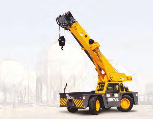
1 INDUSTRIAL CRANE
2 Dimensions Turng (6.4m) 2 Wheel Steer /2 (3.6m) 4 Wheel Steer 14'0" 14 0 (4267) (4267) 12' 1-3/4" (3.7m) 7' 8-1/2" (2350) 6' 3-1/4" (1911) TAILSWING Note: ( ) Reference dimensions mm 40 (12.2m) BOOM 52 (15.6m) BOOM A 17 0 (5182) 21 5 (6528) B 5 3 (1603) 10 2 (3099) C /8 (6340) /2 (7684) 16-3/4" 8-7/8" (425) (225) A 45" (1143) 7' 11-1/2" (2424) 7' 11-1/8" (2416) 46-1/2" (1181) 15" (382) 13-1/4" 27 (334) 27 B 3' 1" (943) 15' 6-1/2" (4737) 8' 5" WHEELBASE (2565) C 3' 1" (943) WORKING WEIGHTS 40 (12.2m) 52 (15.6m) Front Axle 11,900, (5398) 13,900 (6305) Rear Axle 15,600 (7076) 14,850 (6736) GVW 27,500 (12,474) 28,750 (13,041) 2 GROVE YB4415/YB4415XT
3 Workg Range HEIGHT FROM GROUND IN FEET D OFFSET 45 OFFSET BOOM AND EXTENSION LENGTH IN FEET 3'- 8" 3'- 4" MAX BOOM ANGLE OPERATING RADIUS IN FEET FROM AXIS OF ROTATION BOOM DEFLECTION NOT SHOWN AXIS OF ROTATION HEIGHT FROM GROUND IN FEET A BOOM AND EXTENSION LENGTH IN FEET 8 MAX BOOM ANGLE 3'- 8" 3'- 4" OPERATING RADIUS IN FEET FROM AXIS OF ROTATION BOOM DEFLECTION NOT SHOWN AXIS OF ROTATION 70 D HEIGHT FROM GROUND IN FEET LENGTHS IN ( ) ARE BOOM LENGTHS AS READ BY BOOM LENGTH MARKERS (40) 36.4 (35) 31.4 (30) 26.4 (25) 21.4 (20) 18.4 (17) BOOM LENGTH IN FEET 7 MAX BOOM ANGLE 3'-6" 3'-2" AXIS OF ROTATION OPERATING RADIUS IN FEET FROM AXIS OF ROTATION BOOM DEFLECTION NOT SHOWN 3 GROVE YB4415/YB4415XT
4 Superstructure Specifications 17 ft ft. (5.1 m m) three-section full power boom. Maximum tip height: 47 ft. (14.4 m). Speeds: 32 seconds (ext.); 19 seconds (retract). *Optional 21 ft ft. (6.5 m m) three-section full power boom. Maximum tip height: 59 ft. (18.0 m). Speeds: 43 seconds (ext.); 25 seconds (retract). *Fixed Extension (non-offsettable) 15 ft. (4.6 m) swgaway extension w/sgle metallic sheave pot. Stows alongside base boom section for travel. Extends tip heights to 62 ft. (18.9 m) or 74 ft. (22.5 m) with the 40 ft. (12.2 m) and 52 ft. (15.6 m) booms respectively. *Offsettable Extension 15 ft. (4.6 m) swgaway extension w/sgle metallic sheave pot. Stows alongside base boom section for travel. Extends tip heights to 62 ft. (18.9 m) or 74 ft. (22.5 m) with the 40 ft. (12.2 m) and 52 ft. (15.6 m) booms respectively. Can be offset at or 45 to crease up and over reach. Nose Two (2) position low profile and quick reeve design with two metallic sheaves mounted on tapered roller beargs and quick removable p-type rope guards. Head pivots forward (up) to the low profile position (1-2 parts of le only & max 7 boom elevation) for mimizg head space requirements or rearward (down) to the conventional position for maximum lifts that exceed 2 parts of le reevg or approximately 18,000 lbs. (8165 kg). Elevation Tw double actg hydraulic cylders with tegral holdg valves provide elevation from to 8. Mechanical boom angle dicator. Speeds: 20 seconds (ext.) 14 seconds (retract). Anti-Two Block Device - The standard low profile type anti-two block device, when activated, provides an audible-visual warng to the crane operator and disengages all crane functions whose movement can cause two-blockg. * Rated Capacity Limiter (RCL) A simple, effective and easy to use overload protection system conjunction with a low profile type anti-two block (A2B) device assists the operator the efficient operation of the unit. The RCL system constantly monitors actual liftg conditions versus allowable capacity ratgs to assist preventg an overload condition. It provides the operator with a visual pre-warng at approximately 90% of the rated capacity and an audible-visual warng combation with automatic lockout at approximately 100% of rated capacity. Swg Ball bearg swg circle with 36 contuous rotation. Hydraulic motor driven worm and gear reducer. Maximum speed: 2.0 RPM. Hydraulic System Three (3) section ma gear pumps driven off torque converter through PTO. Combed capacity: 75 GPM (285 LPM). Maximum system operatg pressure: 3,500 psi (241 bar). Three valve banks mounted on top of dash panel with direct mechanical lkage low effort lever controls. Return le type filter with full flow by-pass protection and service dicator. 10 micron rated replaceable cartridges. 54 gallon (205 L) reservoir with sight level gauge and steel plate to guard agast side impact damage. *Remote-mounted oil cooler with thermostatically controlled electric motor driven fan. System pressure and flow test ports with quick release type fittgs for each circuit. HOIST SPECIFICATIONS - Model HP12-13G Planetary reduction with automatic sprg applied multi-wet-disc brake and grooved hoist drum. *Cable follower available. Drum Dim. (Dia. x Lg.) x 13.4 (270 mm x 341 mm) Maximum Sgle Le Pull: Maximum Sgle Le Speed: 10,930 lbs. (4958 kg) FPM (41-54 m/m) Maximum Permissible Sgle Le Pull: Standard Rope 5/8 (16 mm) (6 x 37 Class): 9,080 lbs. (3.5:1 FOS) (4119 kg) *Optional Rope 5/8 (16 mm) (18 x 19 Class): 9,080 lbs. (5:1 FOS) (4119 kg) Rope Length (Std.): 250 ft. (76.2 m) w/40 ft. (12.2 m) boom 310 ft. (94.5 m) w/52 ft. (15.6 m) boom Maximum Rope Stowage: 374 ft. of 5/8 (114 m of 16 mm) Usable: 269 ft. of 5/8 (82 m of 16 mm) Counterweight 4,300 lbs. (1950 kg) w/40 ft. (12.2 m) boom; 4,800 lbs. (2177 kg) w/52 ft. (15.6 m) boom; bolted to the turntable. *Denotes optional equipment 4 GROVE YB4415/YB4415XT
5 Chassis Specifications Frame High strength alloy steel construction with tegral outrigger housgs; front/rear liftg, towg and tie down lugs and recessed liftg pots all four corners of deck top. Carry deck constructed of 1/4 (6 mm) thick plate steel w/surface area of 66 sq. ft. (6.1 m 2 ) and anti-skid deck treatment. Outriggers Front and rear oblique type beams at all four corners with tegral holdg valves. Outrigger pads form an tegral part of the beam and have a surface area of 103 sq.. (665 cm 2 ). Maximum outrigger pad load: 26,539 lbs. ( kg). Outrigger Controls, Synchronized Controls are located on dash panel and operate beams pairs from side to side. Two hand sequence mimizes untentional actuation. Sight levelg bubbles located side operator s compartment. *Independent control of each dividual beam is available. Enge, Dual Fuel (Gas/LPG) General Motors 4.3 L, six cylder, dual fuel (LPG/gas) enge, 115 bhp (85 kw) 2,500 RPM. 100 amp alternator. Maximum torque: 275 ft. lbs. (373 2,200 RPM. *Enge, Diesel Cumms 4BT3.9 L turbo-charged diesel, four cylder, 110 bhp (82 kw) 2,500 RPM. Maximum torque: 293 ft. lbs. (397 1,500 RPM. Operator s Control Station The frame mounted, open air style control station with overhead canopy cludes all crane function and drivg controls. Other standard equipment cludes a durable nylon cushion seat with lap belt; hourmeter; sight level bubble and fire extguisher. The dash panel cludes enge oil pressure gauge; enge water temperature gauge; voltmeter; all critical enge monitorg struments; enge/transmission A/V distress system; outrigger controls; *A2B warng dicators; parkg/emergency brake toggle switch with warng light and hooded panel light. The dash panel also cludes an RCL panel and RCL warng dicators when the mache is equipped with the *RCL. All control valves are mounted on top of dash area for ease of operation and creased leg room. Overhead Canopy Tubular steel construction with steel mesh coverg on top and right side grill type guard. Not available with enclosed cab option. *Cab, Enclosed Fully enclosed galvannealed sheet metal structure replaces standard overhead canopy. Includes hot water forced air heater/defroster, safety glass throughout, hged removable door, slidg left and right side glass for cross ventilation, door lock, electric wdshield wiper/ washer, fixed skylight glass, circulatg air fan, rear deck storage shelf area behd operator s seat. Fuel Tank Capacity 46 gallon (175 L) all steel construction w/steel plate to guard agast side impact damage. Electrical System One 12 V - matenance free battery. 875 CCA. Includes standard 12 V remote slave receptacle wired directly to the starter to facilitate jump startg. Automotive type color coded fuses, number coded wirg and water tight connectors. Drive 4 x 2 - Front axle drive only with planetary hubs and limited slip differential. *4 x 4 (YB4415XT) - Front and rear drive/steer axles with planetary hubs and limited slip differentials. Steerg All wheel (4 wheel), full hydraulic power via steerg wheel permits two modes of operation: 2 wheel (rear only) or four-wheel coordated. Inside dashmounted selector switch to select steerg mode. GROVE YB4415/YB4415XT Transmission Remote mounted Clark 3 speed forward and reverse full powershift w/enge mounted torque converter and stalk type shift control mounted to the steerg column. Controls permit quick and easy shuttle control between forward and reverse travel. Axles Front: Planetary drive/steer with ternal multi-wet-disc brakes and limited slip differential. Rear: (4 x 2) Fabricated steer axle with ternal wet disc brakes. (4x4 drive) Planetary drive/steer with ternal wet disc brakes and limited slip differential. Tires Standard 385/65R PR tubeless radial traction tread. Suspension Front: Mounted rigid to frame. Rear: Mounted on rubber blocks to permit oscillation for operation on semiunimproved terra. Brakes Hydraulic actuated ternal wet-disc service brakes actg on all four wheels. A dash mounted toggle switch activates the dry disc parkg brake on the transmission output yoke with a dash mounted warng light. Parkg brake acts on both front wheels of 2 wheel drive models and on all 4 wheels of *4 wheel drive (XT) models. Lights Recessed mounted behd grill type frame cutouts and cludes head, tail, turn signals, brake and 4-way hazard warng lights. Maximum Speed 19 MPH (30 kph) Gradeability (Theoretical) 75% (Based on 27,000 lbs. [ kg] GVW). *Tow Wch Hydraulic wch mounted behd the front bumper area and operated from with the operator s compartment usg the Swg/Tow wch control lever via selector switch. Hydraulic powered unit has a bare drum pull of 6,000 lbs. (2722 kg) at 48 ft./m. (14.6 m/m.) sgle le speed. Includes 100 ft. (30.5 m) length of 3/8 diameter 6 x 25 EIPS IWRC wire rope, hook and thimble, 4 way roller guide and wch mounted drum release lever to permit free spoolg the rope from the drum. Wch is not designed for any type of vertical liftg. Miscellaneous Standard Equipment Hookblock tiedown slg, electronic combation two-tone back-up and outrigger motion alarm, front and rear runng lights, tool stowage well, 15 ton (15 MT) capacity two sheave quick reeve hookblock, powertra audio-visual distress warng system, 12 V remote slave receptacle for jump startg, R/S convex rearview mirror. *Optional Equipment * Worklight package - consists of three 12V, ball mounted, manually adjustable worklights (2-cab/canopy mounted and 1 boom mounted) * 36 amber flashg light wired to ignition switch * Ether jection & block heater cold weather startg kit (less canister) for diesel only * Enge block heater only (Dual Fuel Enge) * Ptle hooks front/rear * Carry deck posts * Spark arrestor muffler(s) (Dual Fuel only) * Sound suppression package for under 90 dba cab noise levels * Dual rearview west coast mirrors * Hydraulic system oil cooler * Quick Reeve Overhaul weight with 5 ton (4.5 MT) hook * Enge tachometer, dash mounted * Deluxe operator s fabric seat w/sprg suspension and dual armrests *Denotes optional equipment 5
6 RATED LIFTING CAPACITIES IN POUNDS ON OUTRIGGERS FULLY EXTENDED FT FT. BOOM *17 (18.4) *20 (21.4) *25 (26.4) *30 (31.4) *35 (36.4) *40 (41.4) 6 30,000 28,950 28,200 27,850 27, ,050 28,100 28,150 27,800 26,400 23, ,000 23,100 23,150 23,200 22,450 20, ,100 18,250 18,350 18,450 18,500 17, ,750 14,850 14,900 14,950 14, ,300 12,450 12,450 12,500 12, ,600 10,650 10,700 10, ,070 9,070 9,070 9, ,760 7,760 7, ,740 6,740 6, ,930 5,930 5, ,260 5, ,710 4, , , ,490 Mimum boom angle ( ) for dicated length (no load) 0 Maximum boom length (ft.) at 0 degree boom angle (no load) 40 Angle Liftg Capacity at Zero Degree Angle On Outriggers Fully Extended 36 *17 (18.4) *20 (21.4) *25 (26.4) *30 (31.4) *35 (36.4) *40 (41.4) 9,080 (13.3) 8,100 (16.3) 5,940 (21.3) 4,600 (26.3) Note: ( ) Reference radii feet. (Applicable to boom nose sheaves down position only.) 3,720 (31.3) 3,070 A B * length varies between boom nose sheaves down position ( bold), or up & out position ( parenthesis). 1. Capacities do not exceed 85% of tippg loads as determed by test accordance with SAE J Capacities appearg above the bold le are based on structural strength and tippg should not be relied upon as a capacity limitation. 3. With boom nose sheaves down ( lower position), sgle, 2-part or 4-part le may be used. With boom nose sheaves up and out (low profile position), sgle or 2-part le may be used, with maximum boom angle limited to 7. THIS CHART IS ONLY A GUIDE AND SHOULD NOT BE USED TO OPERATE THE CRANE. The dividual crane s load chart, operatg structions and other structional plates must be read and understood prior to operatg the crane. 6 GROVE YB4415/YB4415XT
7 STATIONARY - 36 *17 (18.4) *20 (21.4) *25 (26.4) *30 (31.4) *35 (36.4) *40 (41.4) 6 14,700 14,700 14,700 14,700 14, ,500 11,500 11,500 11,500 11,500 11, ,930 8,930 9,050 9,050 9,050 9, ,900 7,020 7,020 7,020 7,020 7, ,400 5,540 5,620 5,680 5, ,320 4,510 4,540 4,600 4, ,600 3,740 3,850 3, ,990 3,120 3,150 3, ,590 2,650 2, ,110 2,170 2, ,740 1,820 1, ,440 1, ,280 1, , Mimum boom angle ( ) for dicated length (no load) 0 Maximum boom length (ft.) at 0 degree boom angle (no load) 40 Liftg Capacity at Zero Degree Angle On Rubber 36 Angle *17 (18.4) *20 (21.4) *25 (26.4) *30 (31.4) *35 (36.4) *40 (41.4) 5,990 (13.3) 4,230 (16.3) 2,430 (21.3) 1,680 (26.3) 1,130 (31.3) 770 Note: ( ) Reference radii feet. (Applicable to boom nose sheaves A B down position only.) * length varies between boom nose sheaves down position ( bold), or up & out position ( parenthesis). 1. Capacities are pounds and do not exceed 75% of tippg loads as determed by test accordance with SAE J Capacities are applicable to maches equipped with 385/65R22.5 (J) Firestone T839 tires at 140 psi cold flation pressure. 3. Defed Arc - Over front cludes 6 on either side of longitudal centerle of mache. 4. Capacities are applicable only with mache on firm level surface. 5. All rubber liftg depends on proper tire flation, capacity and condition. Capacities must be reduced for lower tire flation 6. For pick and carry operation, the boom, usg the shortest practical boom length, must be centered over front of mache. When handlg loads the structural range with capacities close to maximum ratgs, travel should be reduced to creep speed*. 2.5 m.p.h. capacities are permissible on ma boom only, NOT on boom extension. *Creep - not over 200 ft. of movement any 30 mute period and not exceedg 1 mph. 7. With boom nose sheaves down ( lower position), sgle, 2-part or 4-part le may be used. With boom nose sheaves up and out (low profile position), sgle or 2-part le may be used, with maximum boom angle limited to 7. PICK & CARRY AND STATIONARY - DEFINED ARC OVER FRONT *17 (18.4) *20 (21.4) *25 (26.4) *30 (31.4) *35 (36.4) *40 (41.4) 6 18,700 18,700 18,700 18,700 18, ,050 15,050 15,050 15,050 15,050 15, ,500 12,500 12,500 12,500 12,500 12, ,600 10,600 10,600 10,600 10,600 10, ,190 9,190 9,190 9,190 9, ,040 8,040 8,040 8,040 8, ,870 6,870 6,870 6, ,760 5,760 5,760 5, ,910 4,910 4, ,250 4,250 4, ,620 3,710 3, ,270 3, ,800 2, , , ,620 Mimum boom angle ( ) for dicated length (no load) 0 Maximum boom length (ft.) at 0 degree boom angle (no load) 40 Liftg Capacity at Zero Degree Angle On Rubber - Defed Arc and Pick & Carry Angle *17 (18.4) *20 (21.4) *25 (26.4) *30 (31.4) *35 (36.4) *40 (41.4) 9,690 (13.3) 7,920 (16.3) 5,210 (21.3) 3,610 (26.3) 2,630 (31.3) 1,520 Note: ( ) Reference radii feet. (Applicable to boom nose sheaves A B down position only.) * length varies between boom nose sheaves down position ( bold), or up & out position ( parenthesis). THIS CHART IS ONLY A GUIDE AND SHOULD NOT BE USED TO OPERATE THE CRANE. The dividual crane s load chart, operatg structions and other structional plates must be read and understood prior to operatg the crane. GROVE YB4415/YB4415XT 7
8 15 FT. EXTENSION RATED LIFTING CAPACITIES IN POUNDS ON OUTRIGGERS FULLY EXTENDED ,080 9,080 9,080 9, ,080 9,080 9,080 9,080 9,080 9, ,850 9,080 9,080 9,080 9,080 9, ,860 8,450 9,080 9,080 9,080 9, ,060 7,610 8,480 9,080 9,080 9, ,410 6,590 7,730 9,080 9,080 8, ,870 6,340 7,100 8,390 8,330 8, ,410 5,850 6,570 7,750 7,640 7, ,020 5,440 6,110 7,260 7,040 6, ,680 5,070 5,710 6,720 6,530 6, ,380 4,760 5,360 6,140 6,070 5, ,740 4,380 5,050 5,480 5,480 5, ,190 4,770 4,930 4,930 4, ,410 4,470 4,470 4, ,790 4,070 4,070 4, ,730 3,730 3,730 3, ,420 3,420 3, ,160 3,160 3, ,610 2, ,190 Angle Liftg Capacity at Three Degree Angle On Outriggers Fully Extended ,700 (29) Note: ( ) Ref. radii feet. 2,450 (32) 1, All capacities above the bold le are based on structural strength of boom extension and do not exceed 85% of tippg loads on outriggers accordance with SAE J ft. boom extension may be used for sgle le liftg service only. 3. WARNING: Operation of this mache with heavier loads than the capacities listed is strictly prohibited. Mache tippg with boom extension occurs rapidly and without advance warng. 4. Capacities listed are with fully extended outriggers only. 5. No load stability on outriggers fully extended 36 with 15 ft. extension stalled: a. Mimum boom angle for 40 ft. ma boom = b. Maximum ma boom length at ma boom angle = 40 ft. 6. When liftg loads the mimum allowable boom angle is. 1,560 (42) 1,240 (47) 1,000 (52) A D THIS CHART IS ONLY A GUIDE AND SHOULD NOT BE USED TO OPERATE THE CRANE. The dividual crane s load chart, operatg structions and other structional plates must be read and understood prior to operatg the crane. 8 GROVE YB4415/YB4415XT
9 15 FT. EXTENSION STATIONARY ,070 8,070 8,070 **8, ,070 8,070 8,070 8,070 **7, ,070 8,070 8,070 8,070 7,550 7, ,850 7,840 7,710 7,710 7,550 7, ,400 6,300 6,200 6,000 5,890 5, ,250 5,130 5,030 5,030 5,030 5, ,470 4,420 4,420 4,420 4,310 4, ,790 3,790 3,650 3,650 3,620 3, ,260 3,260 3,120 3,120 3,010 3, ,820 2,760 2,640 2,610 2,610 2, ,460 2,430 2,340 2,300 2,300 2, ,170 2,100 2,040 1,980 1,980 1, ,880 1,820 1,720 1,690 1, ,560 1,530 1,470 1, ,390 1,330 1,250 1, ,150 1,150 1,060 1, Liftg Capacity at Three Degree Angle On Rubber Stationary - 36 Angle ,110 (29) 1,760 (32) 1,100 ** This capacity based on maximum boom angle. Note: ( ) Ref. radii feet. 750 (42) 490 (47) A D 1. All capacities above the bold le are based on structural strength of boom extension and do not exceed 75% of tippg loads on rubber accordance with SAE J ft. boom extension may be used for sgle le liftg service only. 3. Defed Arc - Over front cludes 6 on either side of longitudal centerle of mache. Pick and carry liftg NOT permitted. 4. Capacities are applicable to maches equipped with 385/65R22.5 (J) Firestone T839 tires at 140 psi cold flation pressure. 5. Capacities are applicable only with mache on firm level surface. 6. All rubber liftg depends on proper tire flation, capacity and condition. Capacities must be reduced for lower tire flation 7. WARNING: Operation of this mache with heavier loads than the capacities listed is strictly prohibited. Mache tippg with boom extension occurs rapidly and without advance warng. 8. No load stability on rubber 36 with 15 ft. extension stalled: a. Mimum boom angle for 40 ft. ma boom = 3 b. Maximum ma boom length at ma boom angle = 35 ft. 9. When liftg loads the mimum allowable boom angle is. 15 FT. EXTENSION STATIONARY - DEFINED ARC OVER FRONT 6 8,070 8,070 8,070 **8, ,070 8,070 8,070 8,070 7, ,070 8,070 8,070 8,070 7,550 7, ,850 8,070 8,070 8,070 7,550 7, ,060 7,610 8,070 8,070 7,550 7, ,410 6,590 7,730 8,070 7,550 7, ,870 6,340 7,100 7,760 7,550 7, ,410 5,850 6,520 6,520 6,520 6, ,020 5,440 5,580 5,580 5,580 5, ,680 4,840 4,840 4,840 4,840 4, ,240 4,240 4,240 4,240 4,240 4, ,740 3,750 3,750 3,750 3,750 3, ,330 3,330 3,330 3,330 3, ,980 2,980 2,980 2, ,680 2,680 2,680 2, ,410 2,410 2,410 2, ,180 2,180 2, ,970 1,970 1, ,550 1, ,220 Liftg Capacity at Three Degree Angle On Rubber - Defed Arc Over Front Angle 2,700 (29) 2,450 (32) 1,990 ** This capacity based on maximum boom angle. Note: ( ) Ref. radii feet. 1,560 (42) 1,240 (47) 1,000 (52) A D 1. All capacities above the bold le are based on structural strength of boom extension and do not exceed 75% of tippg loads on rubber accordance with SAE J ft. boom extension may be used for sgle le liftg service only. 3. Defed Arc - Over front cludes 6 on either side of longitudal centerle of mache. Pick and carry liftg NOT permitted. 4. Capacities are applicable to maches equipped with 385/65R22.5 (J) Firestone T839 tires at 140 psi cold flation pressure. 5. Capacities are applicable only with mache on firm level surface. 6. All rubber liftg depends on proper tire flation, capacity and condition. Capacities must be reduced for lower tire flation 7. WARNING: Operation of this mache with heavier loads than the capacities listed is strictly prohibited. Mache tippg with boom extension occurs rapidly and without advance warng. 8. No load stability on rubber 36 with 15 ft. extension stalled: a. Mimum boom angle for 40 ft. ma boom = 4 b. Maximum ma boom length at ma boom angle = 30 ft. 9. When liftg loads the mimum allowable boom angle is. THIS CHART IS ONLY A GUIDE AND SHOULD NOT BE USED TO OPERATE THE CRANE. The dividual crane s load chart, operatg structions and other structional plates must be read and understood prior to operatg the crane. GROVE YB4415/YB4415XT 9
10 15 FT. OFFSETTABLE EXTENSION AT OFFSET RATED LIFTING CAPACITIES IN POUNDS ON OUTRIGGERS FULLY EXTENDED ,080 9,080 9,080 9, ,080 9,080 9,080 9,080 9,080 *9, ,180 8,820 9,080 9,080 9,080 9, ,240 7,830 8,760 9,080 9,080 9, ,500 7,030 7,890 8,690 9,080 9, ,840 6,390 7,170 7,920 8,630 9, ,200 5,780 6,580 7,280 7,940 8, ,700 5,210 6,070 6,730 7,350 7, ,270 4,740 5,520 6,260 6,840 7, ,910 4,340 5,060 5,780 6,400 6, ,600 4,000 4,660 5,310 6,000 6, ,330 3,700 4,320 4,940 5,480 5, ,440 4,020 4,600 4,930 4, ,760 4,300 4,470 4, ,530 4,040 4,070 4, ,310 3,730 3,730 3, ,380 3,380 3, ,080 3,080 3, ,460 2, ,980 Liftg Capacity at Three Degree Angle On Outriggers Fully Extended Angle 3,260 (29) 3,260 (32) 3,260 Note: ( ) Ref. radii feet. *This capacity based on maximum boom angle. 2,810 (42) 2,250 (47) 1,820 (52) A All capacities above the bold le are based on structural strength of boom extension and do not exceed 85% of tippg loads on outriggers accordance with SAE J ft. boom extension may be used for sgle le liftg service only. 3. WARNING: Operation of this mache with heavier loads than the capacities listed is strictly prohibited. Mache tippg with boom extension occurs rapidly and without advance warng. 4. Capacities listed are with fully extended outriggers only. 5. No load stability on outriggers fully extended 36 with 15 ft. extension stalled at offset: a. Mimum boom angle for 40 ft. ma boom = b. Maximum ma boom length at ma boom angle = 40 ft. 6. When liftg loads the mimum allowable boom angle is at offset. 15 FT. OFFSETTABLE EXTENSION AT 45 OFFSET RATED LIFTING CAPACITIES IN POUNDS ON OUTRIGGERS FULLY EXTENDED , ,140 4,210 4, ,000 4,070 4,170 4,240 4, ,890 3,950 4,050 4,130 4,200 4, ,810 3,860 3,960 4,040 4,110 4, ,740 3,800 3,880 3,960 4,030 4, ,740 3,820 3,890 3,960 4, ,780 3,830 3,900 3, ,720 3,790 3,850 3, ,760 3,810 3, ,780 3, ,740 3, ,710 3, ,380 Liftg Capacity at Forty Eight Degree Angle On Outriggers Fully Extended - 36 Angle 48 ** 3,710 (23.5) 3,710 (25.7) Note: ( ) Ref. radii feet. ** Radii are with the extension at horizontal. 3,710 (29.2) 3,710 (32.7) 3,670 3,110 (39.8) A All capacities above the bold le are based on structural strength of boom extension and do not exceed 85% of tippg loads on outriggers accordance with SAE J ft. boom extension may be used for sgle le liftg service only. 3. WARNING: Operation of this mache with heavier loads than the capacities listed is strictly prohibited. Mache tippg with boom extension occurs rapidly and without advance warng. 4. Capacities listed are with fully extended outriggers only. 5. No load stability on outriggers fully extended 36 with 15 ft. extension stalled at 45 offset: a. Mimum boom angle for 40 ft. ma boom = 45 b. Maximum ma boom length at 45 ma boom angle = 40 ft. 6. When liftg loads the mimum allowable boom angle is 48 at 45 offset. THIS CHART IS ONLY A GUIDE AND SHOULD NOT BE USED TO OPERATE THE CRANE. The dividual crane s load chart, operatg structions and other structional plates must be read and understood prior to operatg the crane. 10 GROVE YB4415/YB4415XT
11 15 FT. OFFSETTABLE EXTENSION AT OFFSET STATIONARY ,070 8,070 8,070 *8, ,070 8,070 8,070 8,070 *7, ,070 8,070 8,070 8,070 7,550 7, ,240 7,710 7,710 7,710 7,550 7, ,400 6,300 6,200 6,000 5,780 5, ,970 4,920 4,920 4,620 4,570 4, ,170 4,170 4,120 3,900 3,900 3, ,660 3,660 3,440 3,390 3,390 3, ,110 3,060 2,960 2,790 2,680 2, ,680 2,580 2,490 2,430 2,330 2, ,330 2,280 2,160 2,000 2,000 2, ,070 2,050 2,040 1,910 1,810 1, ,810 1,750 1,610 1,560 1, ,440 1,390 1,340 1, ,260 1,190 1,080 1, ,110 1, Liftg Capacity at Three Degree Angle On Rubber - 36 Angle ,940 (29) 1,660 (32) 1,080 Note: ( ) Ref. radii feet. *This capacity based on maximum boom angle. 750 (42) A All capacities above the bold le are based on structural strength of boom extension and do not exceed 75% of tippg loads on rubber accordance with SAE J ft. boom extension may be used for sgle le liftg service only. 3. Defed Arc - Over front cludes 6 on either side of longitudal centerle of mache. Pick and carry liftg NOT permitted. 4. Capacities are applicable to maches equipped with 385/65R22.5 (J) Firestone T839 tires at 140 psi cold flation pressure. 5. Capacities are applicable only with mache on firm level surface. 6. All rubber liftg depends on proper tire flation, capacity and condition. Capacities must be reduced for lower tire flation 7. WARNING: Operation of this mache with heavier loads than the capacities listed is strictly prohibited. Mache tippg with boom extension occurs rapidly and without advance warng. 8. No load stability on rubber 36 with 15 ft. extension stalled at offset: a. Mimum boom angle for 40 ft. ma boom = 38 ; for 35 ft. ma boom = 2 b. Maximum ma boom length at ma boom angle = 30 ft. 9. When liftg loads the mimum allowable boom angle is at offset. 15 FT. OFFSETTABLE EXTENSION AT 45 OFFSET STATIONARY , ,140 4,210 4, ,000 4,070 4,170 4,240 *4, ,890 3,950 4,050 4,130 4,200 4, ,700 3,700 3,700 3,700 3,700 3, ,160 3,160 3,160 3,160 3,160 3, ,730 2,730 2,730 2,730 2, ,370 2,370 2,370 2, ,070 2,070 2,030 2, ,760 1,760 1, ,570 1,570 1, ,320 1, , Liftg Capacity at Forty Eight Degree Angle On Rubber - 36 Angle 48 ** 2,830 (23.5) 2,425 (25.7) Note: ( ) Ref. radii feet. * This capacity based on maximum boom angle. ** Radii are with the extension at horizontal. 1,920 (29.2) 1,530 (32.7) 1, (39.8) A All capacities above the bold le are based on structural strength of boom extension and do not exceed 75% of tippg loads on rubber accordance with SAE J ft. boom extension may be used for sgle le liftg service only. 3. Defed Arc - Over front cludes 6 on either side of longitudal centerle of mache. Pick and carry liftg NOT permitted. 4. Capacities are applicable to maches equipped with 385/65R22.5 (J) Firestone T839 tires at 140 psi cold flation pressure. 5. Capacities are applicable only with mache on firm level surface. 6. All rubber liftg depends on proper tire flation, capacity and condition. Capacities must be reduced for lower tire flation 7. WARNING: Operation of this mache with heavier loads than the capacities listed is strictly prohibited. Mache tippg with boom extension occurs rapidly and without advance warng. 8. No load stability on rubber 36 with 15 ft. extension stalled at 45 offset: a. Mimum boom angle for 40 ft. ma boom = 45 b. Maximum ma boom length at 45 ma boom angle = 40 ft. 9. When liftg loads the mimum allowable boom angle is 48 at 45 offset. THIS CHART IS ONLY A GUIDE AND SHOULD NOT BE USED TO OPERATE THE CRANE. The dividual crane s load chart, operatg structions and other structional plates must be read and understood prior to operatg the crane. GROVE YB4415/YB4415XT 11
12 15 FT. OFFSETTABLE EXTENSION AT OFFSET STATIONARY - DEFINED ARC OVER FRONT 6 8,070 8,070 8,070 *8, ,070 8,070 8,070 8,070 7, ,070 8,070 8,070 8,070 7,550 7, ,240 7,830 8,070 8,070 7,550 7, ,500 7,030 7,890 8,070 7,550 7, ,840 6,390 7,170 7,920 7,550 7, ,200 5,780 6,580 7,280 7,550 7, ,700 5,210 6,070 6,520 6,520 6, ,270 4,740 5,520 5,580 5,580 5, ,910 4,340 4,840 4,840 4,840 4, ,600 4,000 4,240 4,240 4,240 4, ,330 3,700 3,750 3,750 3,750 3, ,300 3,300 3,300 3,300 3, ,930 2,930 2,930 2, ,600 2,600 2,600 2, ,320 2,320 2,320 2, ,070 2,070 2, ,850 1,850 1, ,400 1, ,050 Liftg Capacity at Three Degree Angle On Rubber - Defed Arc Over Front Angle 2,700 (29) Note: ( ) Ref. radii feet. 2,450 (32) *This capacity based on maximum boom angle. 1,990 1,560 (42) 1,240 (47) 930 (52) A All capacities above the bold le are based on structural strength of boom extension and do not exceed 75% of tippg loads on rubber accordance with SAE J ft. boom extension may be used for sgle le liftg service only. 3. Defed Arc - Over front cludes 6 on either side of longitudal centerle of mache. Pick and carry liftg NOT permitted. 4. Capacities are applicable to maches equipped with 385/65R22.5 (J) Firestone T839 tires at 140 psi cold flation pressure. 5. Capacities are applicable only with mache on firm level surface. 6. All rubber liftg depends on proper tire flation, capacity and condition. Capacities must be reduced for lower tire flation 7. WARNING: Operation of this mache with heavier loads than the capacities listed is strictly prohibited. Mache tippg with boom extension occurs rapidly and without advance warng. 8. No load stability on rubber (defed arc) with 15 ft. extension stalled at offset: a. Mimum boom angle for 40 ft. ma boom = b. Maximum ma boom length at ma boom angle = 40 ft. 9. When liftg loads the mimum allowable boom angle is at offset. 15 FT. OFFSETTABLE EXTENSION AT 45 OFFSET STATIONARY - DEFINED ARC OVER FRONT 12 4, ,140 4,210 4, ,000 4,070 4,170 4,240 4, ,890 3,950 4,050 4,130 4,200 4, ,810 3,860 3,960 4,040 4,110 4, ,740 3,800 3,880 3,960 4,030 4, ,740 3,820 3,890 3,960 4, ,780 3,830 3,900 3, ,720 3,750 3,750 3, ,310 3,310 3, ,930 2,930 2, ,610 2, , ,080 Liftg Capacity at Forty Eight Degree Angle On Rubber - Defed Arc Over Front Angle 48 ** 3,710 (23.5) 3,710 (25.7) Note: ( ) Ref. radii feet. ** Radii are with the extension at horizontal. 3,470 (29.2) 2,810 (32.7) 2,280 1,880 (39.8) A ad a e t t e e te s o at o o ta 1. All capacities above the bold le are based on structural strength of boom extension and do not exceed 75% of tippg loads on rubber accordance with SAE J ft. boom extension may be used for sgle le liftg service only. 3. Defed Arc - Over front cludes 6 on either side of longitudal centerle of mache. Pick and carry liftg NOT permitted. 4. Capacities are applicable to maches equipped with 385/65R22.5 (J) Firestone T839 tires at 140 psi cold flation pressure. 5. Capacities are applicable only with mache on firm level surface. 6. All rubber liftg depends on proper tire flation, capacity and condition. Capacities must be reduced for lower tire flation 7. WARNING: Operation of this mache with heavier loads than the capacities listed is strictly prohibited. Mache tippg with boom extension occurs rapidly and without advance warng. 8. No load stability on rubber (defed arc) with 15 ft. extension stalled at 45 offset: a. Mimum boom angle for 40 ft. ma boom = 45 b. Maximum ma boom length at 45 ma boom angle = 40 ft. 9. When liftg loads the mimum allowable boom angle is 48 at 45 offset. THIS CHART IS ONLY A GUIDE AND SHOULD NOT BE USED TO OPERATE THE CRANE. The dividual crane s load chart, operatg structions and other structional plates must be read and understood prior to operatg the crane. 12 GROVE YB4415/YB4415XT
13 80 70 WORKING RANGE DIAGRAM (BOOM DEFLECTION NOT SHOWN) D OFFSET OFFSET 15 HEIGHT FROM GROUND IN FEET BOOM AND EXTENSION LENGTH IN FEET 3' -8" 3' -4" 8 MAX BOOM ANGLE OPERATING RADIUS IN FEET FROM AXIS OF ROTATION WORKING RANGE DIAGRAM (BOOM DEFLECTION NOT SHOWN) D AXIS OF ROTATION 15 HEIGHT FROM GROUND IN FEET BOOM AND EXTENSION LENGTH IN FEET 3' -8" 3' -4" 8 MAX BOOM ANGLE AXIS OF ROTATION OPERATING RADIUS IN FEET FROM AXIS OF ROTATION WORKING RANGE DIAGRAM (BOOM DEFLECTION NOT SHOWN) DB LENGTHS IN ( ) ARE BOOM LENGTHS AS READ BY BOOM LENGTH MARKERS 53.4 (52) 2 PARTS LINE MAXIMUM WHEN USING HOOKBLOCK AT MAX. BOOM ANGLE HEIGHT FROM GROUND IN FEET (45) 41.4 (40) 36.4 (35) 31.4 (30) 26.4 (25) 22.4 (21) BOOM LENGTH IN FEET 7 MAX BOOM ANGLE 3' -6" 3' -2" AXIS OF ROTATION OPERATING RADIUS IN FEET FROM AXIS OF ROTATION GROVE YB4415/YB4415XT 13
14 RATED LIFTING CAPACITIES IN POUNDS ON OUTRIGGERS FULLY EXTENDED FT FT. BOOM *21 (22.8) *25 (26.4) *30 (31.4) *35 (36.4) *40 (41.4) *45 (46.4) *52 (53.4) 6 30,000 25,450 25,100 24,900 **24, ,600 25,450 25,100 24,900 24,200 **21, ,350 22,450 22,550 22,600 22,650 21,800 **18, ,200 18,300 18,400 18,500 18,500 18,550 18, ,150 15,250 15,300 15,400 15,400 15,450 15, ,550 12,700 12,750 12,800 12,850 12,900 12, ,750 10,850 10,900 10,950 10,950 11, ,270 9,400 9,450 9,490 9,500 9, ,090 8,090 8,090 8,090 8, ,000 7,000 7,000 7,000 7, ,130 6,130 6,130 6,130 6, ,410 5,410 5,410 5, ,820 4,820 4,820 4, ,310 4,310 4, ,880 3,880 3, ,510 3,510 3, ,180 3, ,890 2, , ,020 Mimum boom angle () for dicated length (no load) 0 Maximum boom length (ft.) at boom angle (no load) 52 Liftg Capacity at Zero Degree Angle On Outriggers Fully Extended 36 Angle *21 (22.8) *25 (26.4) *30 (31.4) *35 (36.4) *40 (41.4) *45 (46.4) *52 (53.4) 7,190 (17.7) 5,970 (21.3) 4,740 (26.3) 3,850 (31.3) Note: ( ) Reference radii feet. (Applicable to boom nose sheaves down position only.) 3,170 2,630 (41.3) * length varies between boom nose sheaves down position ( bold), or up & out position ( parenthesis). **Capacity based on maximum boom angle. 1,990 (48.3) A Capacities do not exceed 85% of tippg loads as determed by test accordance with SAE J Capacities appearg above the bold le are based on structural strength and tippg should not be relied upon as a capacity limitation. 3. With boom nose sheaves down ( lower position), sgle, 2-part or 4-part le may be used. With boom nose sheaves up and out (low profile position), sgle or 2-part le may be used, with maximum boom angle limited to 7. THIS CHART IS ONLY A GUIDE AND SHOULD NOT BE USED TO OPERATE THE CRANE. The dividual crane s load chart, operatg structions and other structional plates must be read and understood prior to operatg the crane. 14 GROVE YB4415/YB4415XT
15 STATIONARY - 36 *21 (22.8) *25 (26.4) *30 (31.4) *35 (36.4) *40 (41.4) *45 (46.4) *52 (53.4) 6 16,400 16,400 16,400 16,400 **16, ,900 11,900 11,900 11,900 11,900 **11, ,190 9,190 9,190 9,190 9,190 9,190 **9, ,350 7,350 7,350 7,350 7,350 7,350 7, ,540 5,690 5,690 5,690 5,690 5,740 5, ,360 4,360 4,360 4,360 4,360 4,360 4, ,750 3,750 3,750 3,750 3,750 3, ,000 3,000 3,000 3,000 3,000 3, ,590 2,590 2,590 2,590 2, ,030 2,030 2,030 2,030 2, ,790 1,790 1,790 1,790 1, ,500 1,500 1,500 1, ,290 1,290 1,290 1, ,170 1,170 1, Mimum boom angle () for dicated length (no load) Maximum boom length (ft.) at boom angle (no load) 40 Liftg Capacity at Zero Degree Angle On Rubber 36 Angle *21 (22.8) *25 (26.4) *30 (31.4) *35 (36.4) *40 (41.4) 3,700 (17.7) 2,660 (21.3) 1,600 (26.3) 1,050 (31.3) 640 Note: ( ) Reference radii feet. (Applicable to boom nose sheaves A A down position only.) * length varies between boom nose sheaves down position ( bold), or up & out position ( parenthesis). **Capacity based on maximum boom angle. 1. Capacities are pounds and do not exceed 75% of tippg loads as determed by test accordance with SAE J Capacities are applicable to maches equipped with 385/65R22.5 (J) Firestone T839 tires at 140 psi cold flation pressure. 3. Defed Arc - Over front cludes 6 on either side of longitudal centerle of mache. 4. Capacities are applicable only with mache on firm level surface. 5. All rubber liftg depends on proper tire flation, capacity and condition. Capacities must be reduced for lower tire flation 6. For pick and carry operation, the boom, usg the shortest practical boom length, must be centered over front of mache. When handlg loads the structural range with capacities close to maximum ratgs, travel should be reduced to creep speed*. 2.5 m.p.h. capacities are permissible on ma boom only, NOT on boom extension. *Creep - not over 200 ft. of movement any 30 mute period and not exceedg 1 mph. 7. With boom nose sheaves down ( lower position), sgle, 2-part or 4-part le may be used. With boom nose sheaves up and out (low profile position), sgle or 2-part le may be used, with maximum boom angle limited to 7. PICK & CARRY AND STATIONARY - DEFINED ARC OVER FRONT *21 (22.8) *25 (26.4) *30 (31.4) *35 (36.4) *40 (41.4) *45 (46.4) *52 (53.4) 6 19,350 19,350 19,350 19,350 **19, ,500 15,500 15,500 15,500 15,500 **15, ,800 12,800 12,800 12,800 12,800 12,800 **12, ,800 10,800 10,800 10,800 10,800 10,800 10, ,310 9,310 9,310 9,310 9,310 9,310 9, ,100 8,100 8,100 8,100 8,100 8,100 8, ,070 7,070 7,070 7,070 7,070 7, ,150 6,150 6,150 6,150 6,150 6, ,230 5,230 5,230 5,230 5, ,500 4,500 4,500 4,500 4, ,910 3,910 3,910 3,910 3, ,430 3,430 3,430 3, ,020 3,020 3,020 3, ,680 2,680 2, ,380 2,380 2, ,120 2,120 2, ,890 1, ,690 1, , ,070 Mimum boom angle () for dicated length (no load) 0 Maximum boom length (ft.) at boom angle (no load) 52 Liftg Capacity at Zero Degree Angle On Rubber - Defed Arc and Pick & Carry Angle *21 (22.8) *25 (26.4) *30 (31.4) *35 (36.4) *40 (41.4) *45 (46.4) *52 (53.4) 7,190 (17.7) 5,550 (21.3) 3,850 (26.3) 2,800 (31.3) 2,090 1,580 (41.3) 1,060 (48.3) Note: ( ) Reference radii feet. (Applicable to boom nose sheaves A down position only.) * length varies between boom nose sheaves down position ( bold), or up & out position ( parenthesis). **Capacity based on maximum boom angle. THIS CHART IS ONLY A GUIDE AND SHOULD NOT BE USED TO OPERATE THE CRANE. The dividual crane s load chart, operatg structions and other structional plates must be read and understood prior to operatg the crane. GROVE YB4415/YB4415XT 15
16 15 FT. EXTENSION RATED LIFTING CAPACITIES IN POUNDS ON OUTRIGGERS FULLY EXTENDED ,080 9,080 9,080 9, ,080 9,080 9,080 9, ,080 9,080 9,080 9,080 9,080 9, ,370 9,080 9,080 9,080 9,080 9,080 9, ,510 8,150 8,780 9,080 9,080 9,080 9, ,810 7,400 8,060 8,410 8,630 8,980 9, ,220 6,770 7,440 7,810 8,050 8,430 8, ,630 6,240 6,920 7,500 7,770 7,940 8, ,110 5,690 6,430 7,030 7,320 7,510 7, ,680 5,210 5,820 6,180 6,460 7,120 7, ,310 4,800 5,490 5,840 6,320 6,760 6, ,000 4,450 5,090 5,730 5,980 5,980 5, ,720 4,140 4,740 5,330 5,330 5,330 5, ,470 3,870 4,430 4,780 4,780 4,780 4, ,630 4,160 4,310 4,310 4,310 4, ,410 3,900 3,900 3,900 3,900 3, ,540 3,540 3,540 3,540 3, ,230 3,230 3,230 3,230 3, ,590 2,590 2,590 2, ,090 2,090 2, ,690 1, ,370 Mimum boom angle ( ) for dicated length (no load) 0 Maximum boom length (ft.) at boom angle (no load) 52 Angle Liftg Capacity at Three Degree Angle On Outriggers Fully Extended ,210 (33.4) Note: ( ) Ref. radii feet. 3,210 2,950 (42) 1. All capacities above the bold le are based on structural strength of boom extension and do not exceed 85% of tippg loads on outriggers accordance with SAE J ft. boom extension may be used for sgle le liftg service only. 3. WARNING: Operation of this mache with heavier loads than the capacities listed is strictly prohibited. Mache tippg with boom extension occurs rapidly and without advance warng. 4. Capacities listed are with fully extended outriggers only. 5. When liftg loads the mimum allowable boom angle is. 2,370 (47) 1,920 (52) 1,550 (57) 1,150 (64) A THIS CHART IS ONLY A GUIDE AND SHOULD NOT BE USED TO OPERATE THE CRANE. The dividual crane s load chart, operatg structions and other structional plates must be read and understood prior to operatg the crane. 16 GROVE YB4415/YB4415XT
17 15 FT. EXTENSION STATIONARY ,080 9,080 **9, ,080 9,080 9,080 **9, ,080 9,080 9,080 9,080 9, ,970 7,970 7,970 7,910 7,860 7, ,600 6,600 6,480 6,480 6,330 6,330 6, ,480 5,380 5,330 5,280 5,280 5,230 5, ,670 4,550 4,520 4,520 4,520 4,340 4, ,950 3,830 3,700 3,700 3,650 3,650 3, ,370 3,270 3,210 3,210 3,110 3,110 3, ,880 2,850 2,750 2,700 2,600 2,550 2, ,510 2,410 2,360 2,250 2,200 2,200 2, ,160 2,160 2,040 1,940 1,890 1,890 1, ,890 1,840 1,740 1,690 1,580 1,580 1, ,640 1,580 1,430 1,430 1,370 1,370 1, ,370 1,300 1,220 1,170 1,120 1, ,230 1,120 1, Mimum boom angle ( ) for dicated length (no load) Maximum boom length (ft.) at boom angle 30 (no load) Liftg Capacity at Three Degree Angle On Rubber Stationary - 36 Angle ,510 (33.4) 1,130 Note: ( ) Ref. radii feet.. **This capacity based on maximum boom angle. A A 1. All capacities above the bold le are based on structural strength of boom extension and do not exceed 75% of tippg loads on rubber accordance with SAE J ft. boom extension may be used for sgle le liftg service only. 3. Defed Arc - Over front cludes 6 on either side of longitudal centerle of mache. Pick and carry liftg NOT permitted. 4. Capacities are applicable to maches equipped with 385/65R22.5 (J) Firestone T839 tires at 140 psi cold flation pressure. 5. Capacities are applicable only with mache on firm level surface. 6. All rubber liftg depends on proper tire flation, capacity and condition. Capacities must be reduced for lower tire flation 7. WARNING: Operation of this mache with heavier loads than the capacities listed is strictly prohibited. Mache tippg with boom extension occurs rapidly and without advance warng. 8. When liftg loads the mimum allowable boom angle is. 15 FT. EXTENSION STATIONARY - DEFINED ARC OVER FRONT ,080 9,080 9,080 **9, ,080 9,080 9,080 9, ,080 9,080 9,080 9,080 9,080 **9, ,370 9,080 9,080 9,080 9,080 9,080 **9, ,510 8,150 8,780 9,080 9,080 9,080 9, ,810 7,400 8,060 8,410 8,600 8,600 8, ,220 6,770 7,440 7,600 7,600 7,600 7, ,630 6,240 6,760 6,760 6,760 6,760 6, ,110 5,690 5,910 5,910 5,910 5,910 5, ,680 5,110 5,110 5,110 5,110 5,110 5, ,310 4,450 4,450 4,450 4,450 4,450 4, ,920 3,920 3,920 3,920 3,920 3,920 3, ,470 3,470 3,470 3,470 3,470 3,470 3, ,080 3,080 3,080 3,080 3,080 3,080 3, ,750 2,750 2,750 2,750 2,750 2, ,460 2,460 2,460 2,460 2,460 2, ,210 2,210 2,210 2,210 2, ,990 1,990 1,990 1,990 1, ,530 1,530 1,530 1, ,170 1,170 1, Angle Mimum boom angle ( ) for dicated length (no load) 0 Maximum boom length (ft.) at boom angle (no load) 52 Liftg Capacity at Three Degree Angle On Rubber - Defed Arc Over Front ,850 (33.4) 2,330 1,790 (42) **This capacity is based upon maximum boom angle. Note: ( ) Ref. radii feet. 1,370 (47) 1,050 (52) 780 (57) A All capacities above the bold le are based on structural strength of boom extension and do not exceed 75% of tippg loads on rubber accordance with SAE J ft. boom extension may be used for sgle le liftg service only. 3. Defed Arc - Over front cludes 6 on either side of longitudal centerle of mache. Pick and carry liftg NOT permitted. 4. Capacities are applicable to maches equipped with 385/65R22.5 (J) Firestone T839 tires at 140 psi cold flation pressure. 5. Capacities are applicable only with mache on firm level surface. 6. All rubber liftg depends on proper tire flation, capacity and condition. Capacities must be reduced for lower tire flation 7. WARNING: Operation of this mache with heavier loads than the capacities listed is strictly prohibited. Mache tippg with boom extension occurs rapidly and without advance warng. 8. When liftg loads the mimum allowable boom angle is. THIS CHART IS ONLY A GUIDE AND SHOULD NOT BE USED TO OPERATE THE CRANE. The dividual crane s load chart, operatg structions and other structional plates must be read and understood prior to operatg the crane. GROVE YB4415/YB4415XT 17
18 15 FT. OFFSETTABLE EXTENSION AT OFFSET RATED LIFTING CAPACITIES IN POUNDS ON OUTRIGGERS FULLY EXTENDED ,080 9,080 *9, ,080 9,080 9,080 9, ,080 9,080 9,080 9,080 9,080 *9, ,370 9,080 9,080 9,080 9,080 9,080 *9, ,510 8,150 8,780 9,080 9,080 9,080 9, ,810 7,400 8,060 8,410 8,630 8,980 9, ,160 6,770 7,440 7,810 8,050 8,430 8, ,550 6,180 6,920 7,500 7,770 7,940 8, ,050 5,620 6,430 7,030 7,320 7,510 7, ,620 5,150 5,820 6,180 6,460 7,120 7, ,260 4,740 5,420 5,840 6,320 6,600 6, ,940 4,390 5,020 5,650 5,830 5,830 5, ,670 4,090 4,670 5,180 5,180 5,180 5, ,420 3,820 4,370 4,630 4,630 4,630 4, ,580 4,100 4,160 4,160 4,160 4, ,370 3,750 3,750 3,750 3,750 3, ,400 3,400 3,400 3,400 3, ,080 3,080 3,080 3,080 3, ,440 2,440 2,440 2, ,940 1,940 1, ,550 1, ,220 Liftg Capacity at Three Degree Angle On Outriggers Fully Extended - 36 Angle ,210 (33.4) 3,210 2,800 (42) Note: ( ) Ref. radii feet. *This capacity based on maximum boom angle. 2,230 (47) 1,770 (52) 1,410 (57) 1,010 (64) A A 1. All capacities above the bold le are based on structural strength of boom extension and do not exceed 85% of tippg loads on outriggers accordance with SAE J ft. offsettable boom extension may be used for sgle le liftg service only. 3. WARNING: Operation of this mache with heavier loads than the capacities listed is strictly prohibited. Mache tippg with boom extension occurs rapidly and without advance warng. 4. Capacities listed are with fully extended outriggers only. 5. No load stability on outriggers fully extended 36 with 15 ft. offsettable extension stalled at offset: a. Mimum boom angle for 52 ft. ma boom = b. Maximum ma boom length at ma boom angle = 52 ft. 6. When liftg loads the mimum allowable boom angle is at offset. 15 FT. OFFSETTABLE EXTENSION AT 45 OFFSET RATED LIFTING CAPACITIES IN POUNDS ON OUTRIGGERS FULLY EXTENDED ,450 *4, ,280 4,350 *4,420 *4, ,140 4,210 4,290 4,360 *4,420 *4, ,020 4,090 4,180 4,250 4,310 4,360 4, ,920 3,990 4,080 4,150 4,220 4,270 4, ,850 3,910 3,990 4,070 4,130 4,190 4, ,800 3,850 3,920 3,990 4,060 4,120 4, ,710 3,800 3,860 3,930 3,990 4,050 4, ,730 3,820 3,870 3,930 3,990 4, ,780 3,830 3,880 3,940 4, ,710 3,800 3,840 3,890 3, ,750 3,810 3,850 3, ,930 3,750 3,750 3, ,400 3,400 3, ,080 3, ,440 Liftg Capacity at Forty Eight Degree Angle On Outriggers Fully Extended - 36 Angle ** 3,710 (26.7) 3,710 (29.2) 3,630 (32.7) Note: ( ) Ref. radii feet. *This capacity based on maximum boom angle. **Radii are with extension at horizontal. 2,810 2,180 (39.8) 1,680 (43.3) 1,130 (48.3) A A 1. All capacities above the bold le are based on structural strength of boom extension and do not exceed 85% of tippg loads on outriggers accordance with SAE J ft. offsettable boom extension may be used for sgle le liftg service only. 3. WARNING: Operation of this mache with heavier loads than the capacities listed is strictly prohibited. Mache tippg with boom extension occurs rapidly and without advance warng. 4. Capacities listed are with fully extended outriggers only. 5. No load stability on outriggers fully extended 36 with 15 ft. offsettable extension stalled at 45 offset: a. Mimum boom angle for 52 ft. ma boom = 45 b. Maximum ma boom length at 45 ma boom angle = 52 ft. 6. When liftg loads the mimum allowable boom angle is 48 at 45 offset. THIS CHART IS ONLY A GUIDE AND SHOULD NOT BE USED TO OPERATE THE CRANE. The dividual crane s load chart, operatg structions and other structional plates must be read and understood prior to operatg the crane. 18 GROVE YB4415/YB4415XT
30' BOOM 13' 8" (4166) 24' BOOM 11' 8" (3556) 1' 8-1/2" (521) 3' 8-1/2" (1129) 15' 9-1/2" (4813) 17' 9-1/2" (5421)
 24' BOOM 11' 8 (3556) 1' 8-1/2 (521) 3' 8-1/2 (1129) 15' 9-1/2 (4813) 17' 9-1/2 (5421)") INDUSTRIAL CRANE Dimensions 10' 10" (3302) 9' 4" (2845) 6' (1829) TRACK 7' (2134) A B 24' BOOM 11' 8" (3556) 1' 8-1/2" (521) 30' BOOM 13' 8" (4166) 3' 8-1/2" (1129) C 15' 9-1/2" (4813) 17' 9-1/2" (5421)
INDUSTRIAL CRANE Dimensions 10' 10" (3302) 9' 4" (2845) 6' (1829) TRACK 7' (2134) A B 24' BOOM 11' 8" (3556) 1' 8-1/2" (521) 30' BOOM 13' 8" (4166) 3' 8-1/2" (1129) C 15' 9-1/2" (4813) 17' 9-1/2" (5421)
Tire Size 26.5 x 25 5' 5-1/2" (1661) 12' 2-1/4" (3715)
 12' 2-1/4 (3715)") Dimensions 11' 13' 4" (64) TAILSWING 9' " (2997) OVER FENDERS 22' (66) FULL EXT 15' 9" (4801) MID EXT 9' 3-1/2" (2832) RET 9' 9-1/2" (2985) O/R A B C D E F G H 23.5 x 25 5' 4-1/4" (1631) 11' 11-1/2" (36)
Dimensions 11' 13' 4" (64) TAILSWING 9' " (2997) OVER FENDERS 22' (66) FULL EXT 15' 9" (4801) MID EXT 9' 3-1/2" (2832) RET 9' 9-1/2" (2985) O/R A B C D E F G H 23.5 x 25 5' 4-1/4" (1631) 11' 11-1/2" (36)
RT530E. product guide. contents. features 30 ton (30 mt) capacity. Rough Terrain Hydraulic Crane. Features 2. Specifications 3.
 capacity. Rough Terrain Hydraulic Crane. Features 2. Specifications 3.") RT5E product guide contents Features 2 features ton ( mt) capacity 29-95 ft. (8.8-29 m) 4-section full power boom 26- ft. (7.9-13.7 m) telescopic swingaway extension Max main boom tip height of 2.5 ft.
RT5E product guide contents Features 2 features ton ( mt) capacity 29-95 ft. (8.8-29 m) 4-section full power boom 26- ft. (7.9-13.7 m) telescopic swingaway extension Max main boom tip height of 2.5 ft.
ROUGH TERRAIN HYDRAULIC CRANE RT875BXL
 ROUGH TERRAIN HYDRAULIC CRANE RT875BXL Dimensions TAILSWING 14' (4280) 24' (7315) 10' 4" (31) TRACK 8' 4-1/2" (2553) 17' 4" (5283) 26' 6-1/2" (8090) 24' 11" (7595) 43' (13 106) 1' 3" (381) 7' 3" (2210)
TMS500E. product guide. contents. features 40 ton (40 mt) Capacity. Truck Mounted Crane
 Capacity. Truck Mounted Crane") product guide features ton ( mt) Capacity 29 ft.-95 ft. (8.8-29 m) 4 section, full power synchronized boom 26 ft.- ft. (7.9-13.7 m) offsettable telescopic swingaway extension Optional 8,4 lb. (3837 kg)
product guide features ton ( mt) Capacity 29 ft.-95 ft. (8.8-29 m) 4 section, full power synchronized boom 26 ft.- ft. (7.9-13.7 m) offsettable telescopic swingaway extension Optional 8,4 lb. (3837 kg)
Working Range GROVE MODEL TM TON CAPACITY. LIFTING CHARTS - Hydraulic Truck Cranes 9'-7"
 LIFTING CHARTS - Hydraulic Truck Cranes GROVE MODEL - TON CAPACITY Working Range 42-1 ft. (12.8-39.6 m) 33-58 ft. (10.0-17.7 m) 3 FEET 210 200 1 58 48 1 1 33 1 1 1 1 1 115 85 20 10 0 20 10 0 1 1 1 1 1
TMS x 4 & 6 x 6
 TMS5 6 x 4 & 6 x 6 Dimensions 8' (2438) TAILSWING 11' 1" (3383) 7' 8" (2337) RET 13' 9-3/4" (4210) MID EXT ' (96) EXT Note: ( ) Reference dimensions in mm 16-3/4" (425) 43' 4" (13 8) OVERALL 10' 10" (32)
rough Terrain crane 60 tons
 rough Terrain crane 60 tons grove rt700e BOOM LENGTHS: 36 to 110 ft JIB LENGTHS: 33 to 56 ft JIB OFFSETS: 0-25 - 45 NOTES: Specifications Superstructure Boom 11 m - 33,5 m (36 ft - 110 ft) four-section,
features also available.
 features 2 The boom on the is a 29-95 ft. (8.8-29 m) four-section full power boom with a maximum tip height of 2.5 ft. (31.2 m). This synchronized boom uses a single lever joystick control to extend boom
LOAD CHARTS NTC55 85% STABILITY ON OUTRIGGERS
 LOAD CHARTS NTC 5% STABILITY ON OUTRIGGERS 0443 SERIAL NUMBER GA24146 1 TABLE OF CONTENTS GENERAL NOTES... 6-7 WT. REDUCTIONS / LINE PULLS & REEVING INFO / HOIST PERFORMANCE... LIFTING AREA DIAGRAM / BASKET
LOAD CHARTS NBT45 85% STABILITY ON OUTRIGGERS
 LOAD CHARTS NBT45 85% STABILITY ON OUTRIGGERS 295995 SERIAL NUMBER 1 2 TABLE OF CONTENTS GENERAL NOTES...4-5 LIFTING AREA DIAGRAM / LINE PULLS & REEVING INFO / HOIST PERFORMANCE... 6 RANGE DIAGRAM w/ EXTENSION...7
WORKING RANGE DIAGRAM
 Working Range Bi-fold Swingaway 36-110 ft. (11-33.5 m) 33-56 ft. (10.1-17.1 m) 12,1 lbs. (5511 kg) 100% 360 WORKING RANGE DIAGRAM 180 170 160 1 (BOOM DEFLECTION NOT SHOWN) 40 D6-829-101026 0 25 56' 33'
Boom truck 55 tons. national nbt50/55. BOOM LENGTHS: 32 to 128 ft JIB LENGTHS: 26 to 45 ft JIB OFFSETS: 0-30
 Boom truck tons national nbt/ BOOM LENGTHS: 32 to 128 ft JIB LENGTHS: 26 to 45 ft JIB S: 0-30 NOTES: National Crane Series NBT Product Guide ASME B30.5 Imperial % Features 31,1 m (102 ft) four-section
RT530E-2. product guide. contents. features. Rough Terrain Hydraulic Crane. Features 2. Specifications ton (27 mt) capacity.
 capacity.") RT5E-2 product guide contents Features 2 features ton (27 mt) capacity 29 ft. - 95 ft. (8.8 m -29.0 m) 4-section full power boom 26 ft. - ft. (7.9 m - 13.7 m) offsettable telescopic swing-away extension
RT5E-2 product guide contents Features 2 features ton (27 mt) capacity 29 ft. - 95 ft. (8.8 m -29.0 m) 4-section full power boom 26 ft. - ft. (7.9 m - 13.7 m) offsettable telescopic swing-away extension
43' (13.07) 18' 4" (5.59 ) 18' 6" (5.64) Turning Radius: TMS870-45' 1" (13.7 m) TTS870-29' 8" (9.04 m) (8 wheel)
 18' 4 (5.59 ) 18' 6 (5.64) Turning Radius: TMS870-45' 1 (13.7 m) TTS870-29' 8 (9.04 m) (8 wheel)") Dimensions 14' 1/2" (4.28) TAILSWING 7' 7" (2.77) O/R RET. 8' 6" (2.59) 15' 5" (5.64) O/R PART. EXTENDED 24' (7.31) ' 6" (4.5) RETRACTED 137' 9" (1653.62) EXTENDED 43' (13.07) 11' 8-1/4" (3.56) 1' 8" (0.53)
Dimensions 14' 1/2" (4.28) TAILSWING 7' 7" (2.77) O/R RET. 8' 6" (2.59) 15' 5" (5.64) O/R PART. EXTENDED 24' (7.31) ' 6" (4.5) RETRACTED 137' 9" (1653.62) EXTENDED 43' (13.07) 11' 8-1/4" (3.56) 1' 8" (0.53)
Grove YB Product Guide. Features. ASME B30.5 Imperial 85%, Metric 85%, DIN/ISO. 13,6 t (15 USt) capacity
 capacity") Grove YB5515-2 Product Guide ASME B3.5 Imperial 85%, Metric 85%, DIN/ISO Features 13,6 t (15 USt) capacity 12,5 m (41 ft) three-section, full-power synchronized boom 9,1 t (1 USt) deck carrying capacity
Grove YB5515-2 Product Guide ASME B3.5 Imperial 85%, Metric 85%, DIN/ISO Features 13,6 t (15 USt) capacity 12,5 m (41 ft) three-section, full-power synchronized boom 9,1 t (1 USt) deck carrying capacity
RT535E. product guide. contents. features 35 ton (35 mt) capacity. Rough Terrain Hydraulic Crane. Features 2. Specifications 3.
 capacity. Rough Terrain Hydraulic Crane. Features 2. Specifications 3.") product guide contents Features 2 features 35 ton (35 mt) capacity 32-102 ft. (9.8-31.0 m) 4-section full power boom 26-45 ft. (7.6-13.7 m) offsettable telescopic swingaway extension Dual-Axis electric
product guide contents Features 2 features 35 ton (35 mt) capacity 32-102 ft. (9.8-31.0 m) 4-section full power boom 26-45 ft. (7.6-13.7 m) offsettable telescopic swingaway extension Dual-Axis electric
RT540E. product guide. contents. features. Rough Terrain Hydraulic Crane. Features 2. Specifications 3. Dimensions ton (35 mt) capacity
 capacity") RT5E product guide contents Features 2 features ton ( mt) capacity 32 ft. - 2 ft. (9.8 m -31.0 m) 4-section, full power boom 26 ft. - ft. (7.9 m - 13.7 m) offsettable telescopic swing-away extension Full
RT5E product guide contents Features 2 features ton ( mt) capacity 32 ft. - 2 ft. (9.8 m -31.0 m) 4-section, full power boom 26 ft. - ft. (7.9 m - 13.7 m) offsettable telescopic swing-away extension Full
National Crane Series NBT60 Product Guide
 National Crane Series NBT Product Guide ASME B30.5 Imperial % Features 39,01 m (128 ft) five-section full power boom 54,4 t ( USt) at 2,44 m (8 ft) Self-lubricatg Easy Glide wear pads Hydraulically removable
product guide contents features 40 ton (40 mt) Capacity Truck Mounted Crane 29 ft.-95 ft. ( m) 4 section, full power synchronized boom
 Capacity Truck Mounted Crane 29 ft.-95 ft. ( m) 4 section, full power synchronized boom") product guide features ton ( mt) Capacity 29 ft.-95 ft. (8.8-29 m) 4 section, full power synchronized boom 26 ft.- ft. (7.9-13.7 m) offsettable telescopic swingaway extension Optional 8,4 lb. (3837 kg)
product guide features ton ( mt) Capacity 29 ft.-95 ft. (8.8-29 m) 4 section, full power synchronized boom 26 ft.- ft. (7.9-13.7 m) offsettable telescopic swingaway extension Optional 8,4 lb. (3837 kg)
RT875E. product guide. contents
 product guide contents Features 2 Specifications 3 Dimensions 5 Working Range 6 Bifold Load Charts 7 features 75 ton (68 mt) capacity 41 ft-128 ft (12.6 m-39.0 m) 4 section, full power boom 33 ft-56 ft
RT875E. product guide. contents
 product guide contents Features 2 Specifications 3 Dimensions 5 Working Range 6 Bifold Load Charts 7 features 75 ton (68 mt) capacity 41 ft-128 ft (12.6 m-39.0 m) 4 section, full power boom 33 ft-56 ft
Grove TMS700E. Product Guide. Features. 50 t or 55 t (50 USt or 60 USt) capacity
 capacity") Grove TMS700E Product Guide Features 50 t or 55 t (50 USt or 60 USt) capacity 11 m 33,5 m (36 ft 1 ft) four-section, full power sequenced synchronized boom,1 m 17 m (33 ft 56 ft) offsettable bi-fold lattice
Grove TMS700E Product Guide Features 50 t or 55 t (50 USt or 60 USt) capacity 11 m 33,5 m (36 ft 1 ft) four-section, full power sequenced synchronized boom,1 m 17 m (33 ft 56 ft) offsettable bi-fold lattice
RT875E. product guide. contents
 product guide contents Features 2 Specifications 3 Dimensions 5 Working Range 6 Bifold Load Charts 7 features 75 ton (68 mt) capacity 41 ft-128 ft (12.6 m-39.0 m) 4 section, full power boom 33 ft-56 ft
RT600E. product guide. contents
 product guide contents Features 2 features 33-5 ft. (-32 m) 4-section full power boom 29-51 ft. (8.8-15.5 m) telescopic swingaway extension Max main boom tip height of 112 ft. (34 m) E Series cab Max overall
YB7700 Series. product guide. contents. features. Industrial Hydraulic Crane. Features 2. Specifications 3. 2 models YB7720 & YB7720XL
 YB77 Series product guide features 2 models YB772 & YB772XL 2 ton ( mt) capacity 36 on outriggers @ 1 ft. (3.m) radius 15 ton (13.6 mt) deck carrying capacity 15 ton (13.6 mt) on rubber capacity YB772
IC-200-F. Tech Spec. Unmatched in Features and Performance
 Tech Spec IC-2-F Unmatched in Features and Performance * Rated Capacity Limiter...Standard * Capacity on outriggers..., lbs. * Pick and carry capacity... up to 17, lbs. * Height...7 11-1/2 * Width...8
RT700E. product guide. contents
 product guide contents Features 2 Specifications 3 Dimensions 5 Working Range 6 features - ton (-55 mt) capacity 36 ft-1 ft (11 m-33.5 m) 4 section, full power boom 33 ft (.1 m) offsettable lattice swingaway
30' 3-3/8" (9229) RETRACTED 78' (23 796) EXTENDED 10' 11-7/8" (3349) 6' 3" (1905) 1' 11" (587) Note: ( ) Reference dimensions in mm
 RETRACTED 78' (23 796) EXTENDED 10' 11-7/8 (3349) 6' 3 (1905) 1' 11 (587) Note: ( ) Reference dimensions in mm") Dimensions 11' 1-3/8" (3387) TAILSWING 8' 5 1/2" (78) 8' 2" (2489) 18' 6" (5639) EXT 13' (3962) MID EXT 7' 6-3/4" () RET ' 3-3/8" (9229) RETRACTED 78' (23 796) EXTENDED ' 11-7/8" (3349) 6' 3" (1905) 1'
Dimensions 11' 1-3/8" (3387) TAILSWING 8' 5 1/2" (78) 8' 2" (2489) 18' 6" (5639) EXT 13' (3962) MID EXT 7' 6-3/4" () RET ' 3-3/8" (9229) RETRACTED 78' (23 796) EXTENDED ' 11-7/8" (3349) 6' 3" (1905) 1'
TMS900E. product guide. contents. features 90 ton (80 mton) capacity. Truck Crane ft ( m) 5 section full power boom
 capacity. Truck Crane ft ( m) 5 section full power boom") features 90 ton (80 mton) capacity 37-142 ft (11.2-43.2 m) 5 section full power boom Patented TWIN-LOCK boom pinning system 33-56 ft (10-17m) bifold lattice swingaway extension Optional 33-56 ft (10-17
features 90 ton (80 mton) capacity 37-142 ft (11.2-43.2 m) 5 section full power boom Patented TWIN-LOCK boom pinning system 33-56 ft (10-17m) bifold lattice swingaway extension Optional 33-56 ft (10-17
IC-40-2C. Tech Spec. Industrial Crane. Four-wheel drive for tough applications. View thousands of Crane Specifications on FreeCraneSpecs.
 Tech Spec Industrial Crane Four-wheel drive for tough applications Rated Capacity Limiter... Standard Capacity on Outriggers... 9,000 lbs Pick and Carry Capacity... up to 7,200 lbs Height... 6 8 Width...
YB5500 Series. product guide. contents. features
 product guide features 2 models YB5515: 15.T (13.6mt) 3section boom with 41 ft. in. (12.5m) outreach YB551: 1.T (16.3mt) 4section boom with 54 ft. 6 in. (16.6m) outreach 15 ft. (4.6m) offsettable swingaway
24,000 lb. ( kg) counterweight with hydraulic removal system. Cummins ISM 450, six cylinder after cooled 450 hp (336 kw)
 counterweight with hydraulic removal system. Cummins ISM 450, six cylinder after cooled 450 hp (336 kw)") product guide features 41-128 ft. (12.6-39 m) 4 section full power Mega Form boom 33-56 ft. (10-17 m) manual offset bi-fold swingaway 2 x 20 ft. intermediate lattice inserts 24,000 lb. (10 886 kg) counterweight
product guide features 41-128 ft. (12.6-39 m) 4 section full power Mega Form boom 33-56 ft. (10-17 m) manual offset bi-fold swingaway 2 x 20 ft. intermediate lattice inserts 24,000 lb. (10 886 kg) counterweight
IC-200-G. Tech Spec. Industrial Crane. 15-Ton Max. Capacity Under 8 Feet Wide. Manufacturing Corp. Rated Capacity Limiter...
 Tech Spec IC-2-G Industrial Crane -Ton Under 8 Feet Wide Rated Capacity Limiter... Standard Capacity on Outriggers... 3, lbs Pick and Carry Capacity... up to 17, lbs Height... 7 11 Width... 7 1-1/2 Boom
RT700E. product guide. contents
 product guide contents Features 2 Specifications 3 Dimensions 5 Working Range 6 features -60 ton (-55 mt) capacity 36 ft-110 ft (11 m-33.5 m) 4 section, full power boom 33 ft (10.1 m) offsettable lattice
NTC55 Product Guide. Features. ASME B30.5 Imperial 85% 49,9 t (55 USt) capacity at 2,44 m (8 ft)
 capacity at 2,44 m (8 ft)") NTC Product Guide ASME B30.5 Imperial % Features 49,9 t ( USt) capacity at 2,44 m (8 ft) 39,01 m (128 ft) five-section, full-power boom Hydraulically removable counterweight system with multiple configurations
NTC Product Guide ASME B30.5 Imperial % Features 49,9 t ( USt) capacity at 2,44 m (8 ft) 39,01 m (128 ft) five-section, full-power boom Hydraulically removable counterweight system with multiple configurations
TMS500E. product guide. contents. features 40 ton (40 mt) Capacity. Truck Mounted Crane
 Capacity. Truck Mounted Crane") TMS0E product guide features ton ( mt) Capacity 29 ft.-95 ft. (8.8-29 m) 4 section, full power sequenced synchronized boom 26 ft.- ft. (7.9-13.7 m) offsettable telescopic swingaway extension Optional 26
TMS0E product guide features ton ( mt) Capacity 29 ft.-95 ft. (8.8-29 m) 4 section, full power sequenced synchronized boom 26 ft.- ft. (7.9-13.7 m) offsettable telescopic swingaway extension Optional 26
Product Guide. Features
 Grove RT5E-2 Product Guide Features Features Boom shape The RT5E-2 incorporates a rectangular boom shape made from 100 k.s.i. steel which eliminates weight and maximizes structural capacities. Tip height
41' 1-3/4" (12 543) 1' 9" (533) 15' (4572) 2' 7-1/2" (800) 1' 3-1/4" (387) 1' 6-1/4" (464) 6' 1" (1854) 12' 6" (3810) WHEELBASE 11' 1-1/2" (3391)
 1' 9 (533) 15' (4572) 2' 7-1/2 (800) 1' 3-1/4 (387) 1' 6-1/4 (464) 6' 1 (1854) 12' 6 (3810) WHEELBASE 11' 1-1/2 (3391)") Dimensions 11' (33) 13' 4" (64) TAILSWING 9' 10" (2997) OVER FENDERS 22' (66) FULL EXT 15' 9" (4801) MID EXT 9' 3-1/2" (2832) RET 9' 9-1/2" (2985) O/R 11" (282) 34' 1-1/2" (10 3) RET 105' (32 006) EXT
Dimensions 11' (33) 13' 4" (64) TAILSWING 9' 10" (2997) OVER FENDERS 22' (66) FULL EXT 15' 9" (4801) MID EXT 9' 3-1/2" (2832) RET 9' 9-1/2" (2985) O/R 11" (282) 34' 1-1/2" (10 3) RET 105' (32 006) EXT
TIRE SIZE x x 25 A (TRACK) 6 5-1/2 (1969) 6 9-1/8 (2061) B (OAW) 8 (2438) 8 9 (2667) GROUND CLEARANCE 1 7-1/8 (486)
 6 5-1/2 (1969) 6 9-1/8 (2061) B (OAW) 8 (2438) 8 9 (2667) GROUND CLEARANCE 1 7-1/8 (486)") Dimensions 10' 3-1/8" (3127) TAILSWING A B 20' 4-1/2" (6210) 19' (5791) EXT 13' 6" (4115) MID EXT 7' 6" (2286) RET 18' 8-3/8" (59) TIRE SIZE 16.00 x 25 20.5 x 25 A (TRACK) 6 5-1/2 (1969) 6 9-1/8 (2061)
Dimensions 10' 3-1/8" (3127) TAILSWING A B 20' 4-1/2" (6210) 19' (5791) EXT 13' 6" (4115) MID EXT 7' 6" (2286) RET 18' 8-3/8" (59) TIRE SIZE 16.00 x 25 20.5 x 25 A (TRACK) 6 5-1/2 (1969) 6 9-1/8 (2061)
TAILSWING 14' 1-1/2" (4305) 22' 11" (6985) 29.5 x 25 8' 2-1/2" (2502) 12' 5" (3785) 12' 9" (3886) 1' 6-1/2" (470)
 22' 11 (6985) 29.5 x 25 8' 2-1/2 (2502) 12' 5 (3785) 12' 9 (3886) 1' 6-1/2 (470)") View View thousands thousands of of Crane Crane Specifications Specifications on on FreeCraneSpecs.com FreeCraneSpecs.com Dimensions 25' (7620) TAILSWING 14' 1-1/2" (4305) A OAW 10' 11" (3327) 23' (10)
View View thousands thousands of of Crane Crane Specifications Specifications on on FreeCraneSpecs.com FreeCraneSpecs.com Dimensions 25' (7620) TAILSWING 14' 1-1/2" (4305) A OAW 10' 11" (3327) 23' (10)
ROUGH TERRAIN HYDRAULIC CRANE
 ROUGH TERRAIN HYDRAULIC CRANE Dimensions 47' 1" (143 mm) 13' 0.50" (3975 mm) 1' 6.94" (481 mm) 21 DEGREES 19 DEGREES 18' 11.75" (5785 mm) 12' 8.00" (3861 mm) 13' 4.00" (64 mm) 28' 3.00" (8611 mm) 12' 3.00"
24' 11" (7595) 44' 5" (13 557) 7' 3" (2210) 13' 4" (4064) 2' 1" (635) 12' 8" (3861) 1' 8" (508) 28' 3" (8611) Note: ( ) Reference dimensions in mm
 44' 5 (13 557) 7' 3 (2210) 13' 4 (4064) 2' 1 (635) 12' 8 (3861) 1' 8 (508) 28' 3 (8611) Note: ( ) Reference dimensions in mm") Dimensions TAILSWING 14' (4280) 24' (7315) 10' 10-1/2" (3315) TRACK 8' 2-1/2" (2502) 26' (7925) 24' 11" (7595) 11-3/4" (298) 44' 5" (13 557) 7' 3" (2210) 12' 8-3/8" (3870) 20 1' 2-3/8" (365) 2' 1" (6)
Dimensions TAILSWING 14' (4280) 24' (7315) 10' 10-1/2" (3315) TRACK 8' 2-1/2" (2502) 26' (7925) 24' 11" (7595) 11-3/4" (298) 44' 5" (13 557) 7' 3" (2210) 12' 8-3/8" (3870) 20 1' 2-3/8" (365) 2' 1" (6)
TMS700E. product guide. contents. features 50 or 60 ton (50 or 55 mt) Capacity. Truck Mounted Hydraulic Crane. Features 2
 Capacity. Truck Mounted Hydraulic Crane. Features 2") TMS0E product guide features or ton ( or mt) Capacity 36 ft.-1 ft. (11-33.5 m) 4 section, full power sequenced synchronized boom 33 ft.-56 ft. (.1-17 m) offsettable bi-fold lattice swingaway extension
TMS0E product guide features or ton ( or mt) Capacity 36 ft.-1 ft. (11-33.5 m) 4 section, full power sequenced synchronized boom 33 ft.-56 ft. (.1-17 m) offsettable bi-fold lattice swingaway extension
IC-400-3A. Tech Spec. Industrial Crane. 25-Ton Max. Capacity (22,700 kg) Manufacturing Corp. Rated Capacity Limiter... Standard
 Manufacturing Corp. Rated Capacity Limiter... Standard") Tech Spec IC-400-3A Industrial Crane 25-Ton Max. Capacity (22,700 kg) Rated Capacity Limiter... Standard Capacity on Outriggers... 50,000 lbs (22,700 kg) Pick and Carry Capacity... up to 24,400 lbs (11,000
Tech Spec IC-400-3A Industrial Crane 25-Ton Max. Capacity (22,700 kg) Rated Capacity Limiter... Standard Capacity on Outriggers... 50,000 lbs (22,700 kg) Pick and Carry Capacity... up to 24,400 lbs (11,000
GCD15 Product Guide. Features. ASME B30.5 Imperial 85%, Metric 85%
 GCD15 Product Guide ASME B30.5 Imperial 85%, Metric 85% Features 13,6 t (15 USt) capacity 12,5 m (41 ft) three-section full-power boom 8,1 t (9 USt ) deck carrying ability Load sensing hydraulic piston
TRUCK MOUNTED HYDRAULIC CRANE
 TRUCK MOUNTED HYDRAULIC CRANE Dimensions STEERING RADIUS 34' 10" (10617mm) C L ROTATION 12' 0" TAILSWING (3657 mm) 8' 4.0" (25 mm) 6' 10.69" (2100 mm) FRONT TRACK 6' 0.3" (1837 mm) REAR TRACK 7' 10" (23
IC-20-J. Tech Spec. Industrial Crane. Features the exclusive rotating boom
 Tech Spec IC-20-J Industrial Crane Features the exclusive rotating boom Capacity on Outriggers... 5,000 lbs (2,270 kg) Pick and Carry Capacity... up to 2,500 lbs (1,130 kg) Height... 5 6 (1.66 m) w/o Operator
Grove YB4400 Series. Product Guide. Features. View thousands of Crane Specifications on FreeCraneSpecs.com
 Grove YB44 Series Product Guide Features YB449: 7,7 t (8.5 USt) threesection boom with 7,6 m (25 ft 2 in) tip height YB449XL: 7,7 t (8.5 USt) threesection boom with 1,2 m (33 ft 6 in) tip height YB4492:
SCD15 Product Guide. Features. ASME B30.5 Imperial 85%
 SCD15 Product Guide ASME B30.5 Imperial 5% Features 13,6 t (15 USt) capacity 12,5 m (41 ft) three-section full-power boom,1 t (9 USt ) deck carrying ability Load sensing hydraulic piston pump Mechanical
20 Ton Cherry Picker. Grove RT58D with Hi Rail Running Gear Load Charts & Specs
 Ton Cherry Picker Grove with Hi Rail Running Gear Load Charts & Specs Dimensions 15' 11" (4851) I A C 14' 6" (44) 18' 3" (63) A B C D E F G H I TIRE SIZE (TRACK) (O.A.H) (O.A.W) (60' BOOM) (70' BOOM)
Dimensions RT750. Note: ( ) Reference dimensions in mm 10' 10-1/2" (3314) 10' 5" (3175) 23' 4" (7112) 17' 4" (5283) 13' 8" (4166) 22' 11" (6985)
 Reference dimensions in mm 10' 10-1/2 (3314) 10' 5 (3175) 23' 4 (7112) 17' 4 (5283) 13' 8 (4166) 22' 11 (6985)") Dimensions 10' 10-1/2" (3314) 23' 4" (7112) 17' 4" (5283) 10' 5" (3175) 13' 8" (4166) 22' 11" (6985) 43' 7" (13 284) 5' 9" (1753) 13' 5-1/2" (4104) C ROTATION L 2' 8" (813) 17' 6-1/4" (5342) BOOM OVERHANG
Dimensions 10' 10-1/2" (3314) 23' 4" (7112) 17' 4" (5283) 10' 5" (3175) 13' 8" (4166) 22' 11" (6985) 43' 7" (13 284) 5' 9" (1753) 13' 5-1/2" (4104) C ROTATION L 2' 8" (813) 17' 6-1/4" (5342) BOOM OVERHANG
Three-position, out and down style outriggers with lighter polymeric floats
 NBT-1 Capacity: USt (36,3 t) ratg Boom: 142 ft (43,3 m) five-section boom Max tip height ma boom: 1 ft (45,72 m) Max tip height ma boom with jib: 4 ft (62,2 m) Several boom length options providg work
Operating radius in feet from axis of rotation
 LIFTING CHARTS - Hydraulic Truck Cranes GROVE MODEL - 110 TON CAPACITY working range 36-142' main boom 0 Height from the ground in feet Boom and extension length in feet Operating radius in feet from axis
Grove TMS9000E. Product Guide. Features
 Grove TMS9000E Product Guide Features 90 t (110 USt) capacity 11,2 m - 43,3 m (36 ft - 142 ft) five-section full power boom Patented TWIN-LOCK boom pinning system 10 m - 17 m (33 ft - 56 ft) bi-fold lattice
YB5520. Product Guide. Features. ASME B30.5 Imperial 85% 18 t (20 USt) capacity
 capacity") YB552 Product Guide ASME B3.5 Imperial 85% Features 18 t (2 USt) capacity 9,7 t (1 USt ) deck carrying ability 16,6 m (54.5 ft) four-section, four-plate full-power boom Exclusive pivoting boom nose GROVE
YB552 Product Guide ASME B3.5 Imperial 85% Features 18 t (2 USt) capacity 9,7 t (1 USt ) deck carrying ability 16,6 m (54.5 ft) four-section, four-plate full-power boom Exclusive pivoting boom nose GROVE
31' 8-1/2" (9666) 13' 4" (4064) TAILSWING 41' 11-1/2" (12 790) S/S OVERALL 34' 11-1/4" (10 650) RETRACTED 109' 10" (33 477) EXTENDED 7' (2134)
 13' 4 (4064) TAILSWING 41' 11-1/2 (12 790) S/S OVERALL 34' 11-1/4 (10 650) RETRACTED 109' 10 (33 477) EXTENDED 7' (2134)") Dimensions 8' 2" (2489) OVER FENDERS 31' 8-1/2" (9666) 13' 4" (64) TAILSWING 7' 8" (2337) RETRACTED 13' " (4216) MID EXTENDED ' (96) EXTENDED 41' 11-1/2" (12 790) S/S OVERALL 1' 7" (484) 34' 11-1/4" (
Dimensions 8' 2" (2489) OVER FENDERS 31' 8-1/2" (9666) 13' 4" (64) TAILSWING 7' 8" (2337) RETRACTED 13' " (4216) MID EXTENDED ' (96) EXTENDED 41' 11-1/2" (12 790) S/S OVERALL 1' 7" (484) 34' 11-1/4" (
TMS9000E. Preliminary. features. Product Guide. Truck Mounted Crane
 TMS9000E features Preliminary Product Guide 110 ton (90 metric ton) capacity 36-142 ft. (11-43.3 m) 5 section full power boom Patented TWIN-LOCK boom pinning system 33-56 ft. (10-17 m) manual offset bi-fold
24' 11" (7595) 16' 6-1/2" (5042) 2' 1" (635) 1' 8" (155) 12' 8" (3861) Note: ( ) Reference dimensions in mm. Turning Radius...
 16' 6-1/2 (5042) 2' 1 (635) 1' 8 (155) 12' 8 (3861) Note: ( ) Reference dimensions in mm. Turning Radius...") Dimensions 26' 6-1/2" (8090) 24' (7315) EXT 17' 4" (5283) MID EXT ' 4" (31) RET 14' 1/2" (4280) TAILSWING ' 11-1/2" (33) OVER FENDERS 9' (2743) 24' 11" (7595) 11-3/4" (298) 47' 3/4" (14 3) 39' 7" (12 065)
Dimensions 26' 6-1/2" (8090) 24' (7315) EXT 17' 4" (5283) MID EXT ' 4" (31) RET 14' 1/2" (4280) TAILSWING ' 11-1/2" (33) OVER FENDERS 9' (2743) 24' 11" (7595) 11-3/4" (298) 47' 3/4" (14 3) 39' 7" (12 065)
24' (7315) 10' 10-1/2" (3315) 24' 11" (7595) 3' 7" (1310) 1' 2-3/8" (365) 2' 1" (635) 1' 8" (508) 12' 8" (3861) 28' 3" (8611)
 10' 10-1/2 (3315) 24' 11 (7595) 3' 7 (1310) 1' 2-3/8 (365) 2' 1 (635) 1' 8 (508) 12' 8 (3861) 28' 3 (8611)") Dimensions TAILSWING 14' (4280) 24' (7315) 10' 10-1/2" (3315) TRACK 8' 4-1/2" (2553) 26' 6-1/2" (8090) 24' 11" (7595) 3' 7" (1310) 1' 3" (381) 7' 3" (2210) 13' 1/2" (3975) 21 1' 2-3/8" (365) 2' 1" (6)
Dimensions TAILSWING 14' (4280) 24' (7315) 10' 10-1/2" (3315) TRACK 8' 4-1/2" (2553) 26' 6-1/2" (8090) 24' 11" (7595) 3' 7" (1310) 1' 3" (381) 7' 3" (2210) 13' 1/2" (3975) 21 1' 2-3/8" (365) 2' 1" (6)
Grove YB4400 Series. Product Guide. Features. YB4409: 7,7 t (8.5 USt) three-section boom with 7,6 m (25 ft 2 in) tip height
 three-section boom with 7,6 m (25 ft 2 in) tip height") Grove YB4 Series Product Guide Features YB49: 7,7 t (8.5 USt) threesection boom with 7,6 m (25 ft 2 in) tip height YB49XL: 7,7 t (8.5 USt) threesection boom with,2 m (33 ft 6 in) tip height YB492: 8,1
Grove YB4 Series Product Guide Features YB49: 7,7 t (8.5 USt) threesection boom with 7,6 m (25 ft 2 in) tip height YB49XL: 7,7 t (8.5 USt) threesection boom with,2 m (33 ft 6 in) tip height YB492: 8,1
Grove YB4400 Series Product Guide
 Grove YB44 Series Product Guide Features YB449: 7,7 t (8. USt) threesection boom om with 7,6 m (2 ft 2 in) tip height YB449XL: 7,7 t (8. USt) threesection boom with 1,2 m (33 ft 6 in) tip height YB4492:
Rough Terrain Crane. 65 U.S. Tons (59 Metric 10 ft Radius ft, 5 Section Main Boom 30.2 ft 52.5 ft Boom Extension.
 SRC865XL Rough Terrain Crane 65 U.S. Tons (59 Metric Tons) @ 10 ft Radius 139.4 ft, 5 Section Main Boom 30.2 ft 52.5 ft Boom Extension Product Guide key FEATURES OPERATOR S CAB Spacious ergonomic cab with
IC-35-D. Engineering Spec. Page 1 of 8 Date: June 2006
 Engineering Spec IC-35-D Page 1 of 8 Replaces: Form HD14D Dated: May 24 BMC s IC-35-2D is a Self-Propelled Industrial Crane designed for in-plant lifting and material handling applications. It has special
24' 11" (7595) 44' 5" (13 557) 7' 3" (2210) 13' 4" (4064) 12' 8" (3861) 28' 3" (8611) Note: ( ) Reference dimensions in mm
 44' 5 (13 557) 7' 3 (2210) 13' 4 (4064) 12' 8 (3861) 28' 3 (8611) Note: ( ) Reference dimensions in mm") Dimensions 14' (4280) TAILSWING 24' (7315) ' 4" (31) TRACK 8' 2-1/2" (22) ' -1/2" (3315) 26' (7925) 17' 4" (5283) 24' 11" (95) 11-3/4" (298) 44' 5" (13 557) 7' 3" (22) 12' 8-3/8" (3870) 20 1' 2-3/8" (3)
Dimensions 14' (4280) TAILSWING 24' (7315) ' 4" (31) TRACK 8' 2-1/2" (22) ' -1/2" (3315) 26' (7925) 17' 4" (5283) 24' 11" (95) 11-3/4" (298) 44' 5" (13 557) 7' 3" (22) 12' 8-3/8" (3870) 20 1' 2-3/8" (3)
GCD25 Product Guide. Features. ASME B30.5 Imperial 85%, Metric 85%
 GCD25 Product Guide ASME B30.5 Imperial 85%, Metric 85% Features 22,7 t (25 USt) capacity 21,6 m (71 ft) four-section full-power boom 13,6 t (15 USt ) deck carrying ability Tilt steering wheel Load sensing
National Crane Series NBT40
 National Crane Series NBT40 Product Guide Features 36,3 t (40 USt) ratg 43,3 m (142 ft) five-section boom Self-lubricatg Easy Glide wear pads 862 kg (1900 lb) tailswg counterweight Features National Crane
SCD25 Product Guide. Features. ASME B30.5 Imperial 85%
 SCD25 Product Guide ASME B30.5 Imperial 85% Features 22,7 t (25 USt) capacity 21,6 m (71 ft) four-section full-power boom 13,6 t (15 USt ) deck carrying ability Tilt steering wheel Load sensing hydraulic
RT-300-B. Tech Spec. Preliminary Information. * 30,000 pounds capacity at 10 ft. radius. * 4-wheel drive. * 4-wheel steer
 Tech Spec RT-300-B * 30,000 pounds capacity at 10 ft. radius * 4-wheel drive * 4-wheel steer * 360 degree continuous rotation * 60 ft. of full power main boom reach RT-300-2B CAPACITIES APPLY TO OPERATION
21' (6400) 4' 10" (1474) 9' 7" (2921) 20' (6096) WHEELBASE 40' 9" (12 421) C ROTATION. Note: ( ) Reference dimensions in mm
 4' 10 (1474) 9' 7 (2921) 20' (6096) WHEELBASE 40' 9 (12 421) C ROTATION. Note: ( ) Reference dimensions in mm") TM9 Dimensions 14' 7" (4448) TAILSWING 27' 6-1/2" (8395) 17' 5" (58) O/R MID EXTENSION 10' 11-1/2" (33) 25' (7620) 21' (60) 2' 7-3/4" (6) ' 5-1/4" (15 373) 7' 3-5/8" (2226) 12' 11-1/4" (3943) 16 13 5'
TM9 Dimensions 14' 7" (4448) TAILSWING 27' 6-1/2" (8395) 17' 5" (58) O/R MID EXTENSION 10' 11-1/2" (33) 25' (7620) 21' (60) 2' 7-3/4" (6) ' 5-1/4" (15 373) 7' 3-5/8" (2226) 12' 11-1/4" (3943) 16 13 5'
\\\\\\\\\\\\\\\\\\\\\\\\\\\\\\\\\\\\\\\\\\\\\\\\\\\\\\\
 INDUSTRIAL / OIL & GAS / MINING CD4415 ROUGH TERRAIN CRANE Optional equipment shown and subject to change \\\\\\\\\\\\\\\\\\\\\\\\\\\\\\\\\\\\\\\\\\\\\\\\\\\\\\\ BIG JOB? SMALL SPACE? NO PROBLEM. The new
National Crane Series NBT45 Product Guide
 National Crane Series NBT45 Product Guide ASME B.5 Imperial 85% Features,8 t (45 USt) ratg 49,1 m (161 ft) five-section boom Self-lubricatg Easy Glide wear pads 41 kg ( lb) tailswg counterweight Features
National Crane Series NBT45 Product Guide
 National Crane Series NBT45 Product Guide ASME B.5 Imperial 85% Features,8 t (45 USt) ratg 49,1 m (161 ft) five-section boom Self-lubricatg Easy Glide wear pads 41 kg ( lb) tailswg counterweight Features
IC-80-H. Engineering Spec. Page 1 of 15 Date: Aug 2009
 Engineering Spec Manufacturing Corp. (913) 888-0606 FAX (913) 888-8431 www.bmccranes.com IC-80-H Page 1 of 15 Replaces: Dated: The IC-80-H is a self-propelled Industrial Crane designed for in-plant lifting
IC-20-G. Engineering Spec. View thousands of Crane Specifications on FreeCraneSpecs.com. Page 1 of 7 Date: June 2006
 Engineering Spec IC-20-G Page 1 of 7 Replaces: Form BD104G Dated: May 2004 The IC-20-1G is a self-propelled industrial crane designed for in-plant lifting and material handling applications. It is powered
IC-80-1J: 3-section hydraulically extended boom with capacity of 18,000 pounds (8,160 kg) at a 5-foot load (1.5 m) load radius.
 at a 5-foot load (1.5 m) load radius.") IC-80-J ENGINEERING SPEC Page 1 of 14 Replaces Form CD111J Dated November 2011 The IC-80-J is a self-propelled Industrial Crane designed for in-plant lifting and material handling applications, with special
IC-80-J ENGINEERING SPEC Page 1 of 14 Replaces Form CD111J Dated November 2011 The IC-80-J is a self-propelled Industrial Crane designed for in-plant lifting and material handling applications, with special
SRC885. Product Guide. Rough Terrain Crane. 85 U.S. Tons (75 Metric 10 ft Radius 148 ft Max Tip Height (Main Boom) 52.5 ft Boom Extension
 52.5 ft Boom Extension") SRC885 Rough Terrain Crane 85 U.S. Tons (75 Metric Tons) @ 10 ft Radius 148 ft Max Tip Height (Main Boom) 52.5 ft Boom Extension Product Guide 2 SRC885 MOBILE LIFTING POWER WHERE YOU NEED IT SANY America
SRC885 Rough Terrain Crane 85 U.S. Tons (75 Metric Tons) @ 10 ft Radius 148 ft Max Tip Height (Main Boom) 52.5 ft Boom Extension Product Guide 2 SRC885 MOBILE LIFTING POWER WHERE YOU NEED IT SANY America
SRC885. Product Guide. Rough Terrain Crane. View thousands of Crane Specifications on FreeCraneSpecs.com
 SRC885 Rough Terrain Crane 85 U.S. Tons (75 Metric Tons) @ 10 ft Radius 148 ft Max Tip Height (Main Boom) 52.5 ft Boom Extension Product Guide 2 SRC885 MOBILE LIFTING POWER WHERE YOU NEED IT SANY America
IC-100-A: 3-section hydraulically extended boom with capacity of 20,000 pounds (9,000 kg) at a 5-foot load (1.5 m) radius.
 at a 5-foot load (1.5 m) radius.") IC-100-A ENGINEERING SPEC Page 1 of 10 The IC-100-A is a self-propelled 10 US ton rated Industrial Carry Deck Crane designed for in-plant lifting and material handling applications. It is designed to incorporate
IC-100-A ENGINEERING SPEC Page 1 of 10 The IC-100-A is a self-propelled 10 US ton rated Industrial Carry Deck Crane designed for in-plant lifting and material handling applications. It is designed to incorporate
8 feet 4 inches (2.54m) 11 feet 2 inches (3.4m) 9 feet 5 inches (2.87m) 15 inches (38cm) 23 MPH (37 km/h)
 11 feet 2 inches (3.4m) 9 feet 5 inches (2.87m) 15 inches (38cm) 23 MPH (37 km/h)") Page 1 of 9 RT-300-G ENGINEERING SPEC Replaces Form GD111F Dated June 2011 BMC s RT-300 Rough Terrain Crane is a self-propelled crane designed for lifting and material handling applications, with the special
Page 1 of 9 RT-300-G ENGINEERING SPEC Replaces Form GD111F Dated June 2011 BMC s RT-300 Rough Terrain Crane is a self-propelled crane designed for lifting and material handling applications, with the special
25' (3407) 7' 9-3/4" (7620) 8' 8-1/2" (2654) (4064) (597) 1' 11-1/2" 1' 2" (356) 3' 4" (1016) 10' 1" (3073) WHEELBASE 10' 5" (3175) C ROTATION
 7' 9-3/4 (7620) 8' 8-1/2 (2654) (4064) (597) 1' 11-1/2 1' 2 (356) 3' 4 (1016) 10' 1 (3073) WHEELBASE 10' 5 (3175) C ROTATION") Dimensions ' (76) 11' 2" (37) TAILSWING ' (76) 11' 2" (37) 7' 9-3/4" TAILSWING (2432) OVER FENDERS TURNING RADIUS - (2 Wheel Steer) 29' 6" (9029) (4 Wheel Steer) ' 3" (6166) 7' 9-3/4" (2432) OVER FENDERS
Dimensions ' (76) 11' 2" (37) TAILSWING ' (76) 11' 2" (37) 7' 9-3/4" TAILSWING (2432) OVER FENDERS TURNING RADIUS - (2 Wheel Steer) 29' 6" (9029) (4 Wheel Steer) ' 3" (6166) 7' 9-3/4" (2432) OVER FENDERS
TMS900E. product guide. contents. features 90 ton (80 mton) capacity. Truck Crane ft ( m) 5 section full power boom
 capacity. Truck Crane ft ( m) 5 section full power boom") features 90 ton (80 mton) capacity 37-142 ft (11.2-43.2 m) 5 section full power boom Patented TWIN-LOCK boom pinning system 33-56 ft (10-17m) bifold lattice swingaway extension Optional 33-56 ft (10-17
features 90 ton (80 mton) capacity 37-142 ft (11.2-43.2 m) 5 section full power boom Patented TWIN-LOCK boom pinning system 33-56 ft (10-17m) bifold lattice swingaway extension Optional 33-56 ft (10-17
RT530E-2 Product Guide
 RT530E-2 Product Guide ASME B30.5 Imperial 85% Features 30 t (30 USt) capacity 8,8 m 29 m (29 ft 95 ft) four-section fullpower boom 7,9 m 13,7 m (26 ft 45 ft) offsettable telescopic swingaway extension
Grove YB4400 Series Product Guide ASME B30.5 Imperial 85%, Metric 85% and DIN/ISO
 Grove YB44 Series Product Guide ASME B3. Imperial 8%, Metric 8% and DIN/ISO Features YB449: 7,7 t (8. USt) threesection boom with 7,6 m (2 ft 2 in) tip height YB449XL: 7,7 t (8. USt) threesection boom
RTC-8070 TELESCOPIC ROUGH TERRAIN CRANE 70-Ton (63.50 mt)
") RTC-8070 TELESCOPIC ROUGH TERRAIN CRANE 70-Ton (63.50 mt) 70-ton at a 9-foot radius 101,400 lbs. gross vehicle weight (fully loaded) 127-foot, full power, four-section boom with quick reeve boom head 67-foot,
RTC-8070 TELESCOPIC ROUGH TERRAIN CRANE 70-Ton (63.50 mt) 70-ton at a 9-foot radius 101,400 lbs. gross vehicle weight (fully loaded) 127-foot, full power, four-section boom with quick reeve boom head 67-foot,
\\\\\\\\\\\\\\\\\\\\\\\\\\\\\\\\\\\\\\\\\\\\\\\\\\\\\\\
 INDUSTRIAL / OIL & GAS / MINING CD4415 ROUGH TERRAIN CRANE PRELIMINARY SPECIFICATION GUIDE BIG JOB? SMALL SPACE? NO PROBLEM. The new Badger CD4415 Rough Terrain Crane features: Rated capacity: 15 Ton (13.6
RTC Technical Data. Specifications & Capacities. Telescopic Boom Rough Terrain Crane 65 ton (58.9 metric ton) D7
 D7") 5448---0205---D7 1 Technical Data Specifications & Capacities RTC -8065 Telescopic Boom Rough Terrain Crane 65 ton (58.9 metric ton) CAUTION: This material is supplied for reference use only. Operator
5448---0205---D7 1 Technical Data Specifications & Capacities RTC -8065 Telescopic Boom Rough Terrain Crane 65 ton (58.9 metric ton) CAUTION: This material is supplied for reference use only. Operator
RT-300-2F. Engineering Spec. Page 1 of 9 Date: June 2011
 Engineering Spec Manufacturing Corp. (913) 888-0606 FAX (913) 888-8431 www.bmccranes.com RT-300-2F Page 1 of 9 Replaces: Form GD108E Dated: June 2008 BMC s RT-300 Rough Terrain Crane is a self-propelled
Cranes. Truck Crane Features T340-1/T340-1XL
 Truck Crane Features T340-1/T340-1XL Cranes FEATURES 30-40 tons (27-36 mt) maximum lifting capacity 94' (28.6 m) or 105' (32.0 m) maximum boom length 147' (44.8 m) or 158' (48.1 m) maximum tip height Four-section
TMS500E. product guide. contents. features 40 ton (40 mt) Capacity. Truck Mounted Crane
 Capacity. Truck Mounted Crane") product guide features ton ( mt) Capacity 29 ft.-95 ft. (8.8-29 m) 4 section, full power synchronized boom 26 ft.- ft. (7.9-13.7 m) offsettable telescopic swingaway extension Optional 8,4 lb. (3837 kg)
product guide features ton ( mt) Capacity 29 ft.-95 ft. (8.8-29 m) 4 section, full power synchronized boom 26 ft.- ft. (7.9-13.7 m) offsettable telescopic swingaway extension Optional 8,4 lb. (3837 kg)
IC-80-1G IC-80-2G IC-80-3G
 Engineering Spec IC-80-G Page 1 of 10 Replaces: Form CD103F Dated: Jan. 2003 The IC-80-G is a self-propelled Industrial Crane designed for in-plant lifting and material handling applications, with special
IC-400-A ENGINEERING SPEC. (913) Page 1 of 11 Date January Replaces Form LD114A Dated June 2014
 Page 1 of 11 Date January Replaces Form LD114A Dated June 2014") Page 1 of 11 ENGINEERING SPEC Replaces Form LD114A Dated June 2014 The IC-400-3A is a self-propelled Industrial Crane designed for lifting and material handling, with special features of self-loading cargo
Page 1 of 11 ENGINEERING SPEC Replaces Form LD114A Dated June 2014 The IC-400-3A is a self-propelled Industrial Crane designed for lifting and material handling, with special features of self-loading cargo
IC-250-3C. Engineering Spec. Page 1 of 11 Date: Mar. 2009
 Engineering Spec Manufacturing Corp. (913) 888-0606 FAX (913) 888-8431 www.bmccranes.com IC-250-3C Page 1 of 11 Replaces: Form ID108C Dated: Oct. 2008 The IC-250-3C is a self-propelled Industrial Crane
13' 4" (4064) TAILSWING 30' 11" (9423) 41' 10-1/2" (12 764) 7' (2134) TURNING RADIUS w/16" Tires COORDINATED STEER 24' 11" (7595)
 TAILSWING 30' 11 (9423) 41' 10-1/2 (12 764) 7' (2134) TURNING RADIUS w/16 Tires COORDINATED STEER 24' 11 (7595)") Dimensions 20' (6096) 13' 10" (4216) 13' 4" (4064) TAILSWING 8' 5-1/2" (2578) 22' (6706) 30' 11" (9423) FRONT STEER 41' 8" (12 700) TURNING RADIUS w/16" Tires COORDINATED STEER 24' 11" (7595) FRONT STEER
Dimensions 20' (6096) 13' 10" (4216) 13' 4" (4064) TAILSWING 8' 5-1/2" (2578) 22' (6706) 30' 11" (9423) FRONT STEER 41' 8" (12 700) TURNING RADIUS w/16" Tires COORDINATED STEER 24' 11" (7595) FRONT STEER
TADANO ROUGH TERRAIN CRANE : GR-700EX. (Left-hand steering) G E N E R A L D ATA
 G E N E R A L D ATA") SPEC. SHEET No. GR-7E-1-214/EU-51 DATE June, 21 TADANO ROUGH TERRAIN CRANE MODEL : GR-7EX (Left-hand steering) G E N E R A L D ATA CRANE CAPACITY BOOM 7, kg at 3. m 5-section, 11.5 m 44. m DIMENSION Overall
SPEC. SHEET No. GR-7E-1-214/EU-51 DATE June, 21 TADANO ROUGH TERRAIN CRANE MODEL : GR-7EX (Left-hand steering) G E N E R A L D ATA CRANE CAPACITY BOOM 7, kg at 3. m 5-section, 11.5 m 44. m DIMENSION Overall
ROUGH TERRAIN HYDRAULIC CRANE
 ROUGH TERRAIN HYDRAULIC CRANE Dimensions 44' 1.83" (13458 mm) C L ROTATION 11' 10.88" (3629 mm) 1' 7.49" (195 mm) 1' 5.69" (449 mm) 22 DEGREES 11.05" (281 mm) 10' 10.32" (54444 mm) 11' 3.12" (3432 mm)
product guide contents features Industrial Hydraulic Crane Features 2 Specifications 3
 product guide features 22 ton (19.9 mt) capacity 360 on outriggers @ 8.5 ft. (2.6m) radius 15 ton (13.6 mt) deck carrying capacity 15 ton (13.6 mt) on rubber capacity 43 ft. (13.1m) 3-section boom or 67
IC-80-1G IC-80-2G IC-80-3G
 Engineering Spec IC-80-G Page 1 of 10 Replaces: Form CD103F Dated: Jan. 2003 The IC-80-G is a self-propelled Industrial Crane designed for in-plant lifting and material handling applications, with special
45 7 (13.89 m) (2.02 m) (1.68 m) 25 (0.65 m) (0.34 m) 11 0 (3.35 m) 19 3 (5.86 m) (8.17 m) 1 8 (0.50 m)
 (2.02 m) (1.68 m) 25 (0.65 m) (0.34 m) 11 0 (3.35 m) 19 3 (5.86 m) (8.17 m) 1 8 (0.50 m)") Specifications Telescopic Boom Truck Crane HTC 8670 70 ton (63.5 metric tons) 38 0 (11.58 m) 45 7 (13.89 m) 11 6.88 (3.52 m) Link Be HTC 8670 10 8.88 (3.71 m) 6 7.69 (2.02 m) 5 6.25 (1.68 m) 17 17 4.5
Specifications Telescopic Boom Truck Crane HTC 8670 70 ton (63.5 metric tons) 38 0 (11.58 m) 45 7 (13.89 m) 11 6.88 (3.52 m) Link Be HTC 8670 10 8.88 (3.71 m) 6 7.69 (2.02 m) 5 6.25 (1.68 m) 17 17 4.5
IC-40-2C. Engineering Spec. Page 1 of 8 Date: July Form JD112C. Manufacturing Corp. Replaces: Dated:
 Engineering Spec Manufacturing Corp. (913) 888-0606 FAX (913) 888-8431 www.broderson.net IC-40-2C Page 1 of 8 Replaces: Dated: BMC s IC-40-2C is a self-propelled, industrial crane designed for in-plant