Operator s Manual CE/Australian Specifications
|
|
|
- Luke Hines
- 6 years ago
- Views:
Transcription
1 Operator s Manual CE/Australian Specifications ART_ ERT -- Serial # Up 3259ERT -- Serial # Up Specifications inside cover Introduction Safety Safety Alert Symbols Fall Protection Electrocution Hazard Tip-over Hazards Fall Hazards Collision Hazards Additional Safety Hazards Battery Safety Controls & Components Platform Controls Lower Controls Component Locations Workplace Inspection Operating Instructions & Function Tests Prestart Base Controls Operation and Test Platform Control Operation and Test Control Lever Operation Shutdown Procedure Deck Extension Sheet Materials Rack Pothole Protection Bars Outrigger Operation (optional on 2659) Emergency Lowering System Fold Down Platform Railings Battery Charger Charge Batteries Maintenance Routine Maintenance Frequent and Annual Maintenance Maintenance Lock Lubrication Machine Inspections and Maintenance Pre-Start Inspection Checklist Frequent Inspection Checklist Annual Inspection Report Warning and Instructional Decals Troubleshooting Transport and Lifting Instructions Loading Lifting and Tie Down Instructions Novmber 23, 2011 Multiple patents pending. Original Instructions
2 Specifications 2659ERT 3259ERT Working Height* 32 ft 9.8 m 38 ft 11.6m Platform Height 25.5 ft 7.8 m 31.5 ft 9.6 m Maximum Drive Height 25.5 ft 7.8 m 31.5 ft 9.6 m Stowed Height Top Guardrail 90 in m 96 in m Rails Folded 75 in m 82 in m Platform Floor 45 in m 51 in m Guardrail Height 43.5 in m 43.5 in m Toeboard Height 6 in. 15 cm 6 in. 15 cm Ground Clearance 6 in. 15 cm 6 in. 15 cm Machine Weight** (Unloaded, no outriggers) 6820 lb 3090 kg n/a Machine Weight** (Unloaded, with outriggers) 7320 lb 3320 kg 8040 lb 3645 kg Lift Capacity Total 1000 lb 450 kg 750 lb 340 kg Platform 750 lb 340 kg 500 lb 227 kg Sheet Material Rack 250 lb 113 kg 250 lb 113 kg Deck Extension Capacity 1 Person / 250lb (113 kg) 1 Person / 250lb (113 kg) Maximum Occupants 3 2 Length-Stowed (Overall) 103 in m 103 in m Length-Stowed (Without Step) 105 in m 105 in m Platform Length (Extended) in m in m Platform Length (Retracted) 91 in m 91 in m Width (Overall) 59 in. 1.5 m 59 in. 1.5 m Platform Width (Outside) 46 in cm 46 in cm Sheet Rack Width 8 in. 20 cm 8 in. 20 cm Wheel Base 82 in 2.1 m 82 in 2.1 m Turning Radius--Inside 59 in. 1.5 m 59 in. 1.5 m Ground Clearance 6 in 15 cm 6 in 15 cm Drive Speed Stowed mph 0-5 km/h mph km/h (Proportional) Raised or extended 0-.4 mph km/h 0-.4 mph km/h Gradability 33%/ %/16.7 Breakover Angle 30%/16.7 Ground Pressure/Wheel (no outriggers) 97 psi 6.7 kg/cm 2 n/a Ground Pressure/Wheel (with outriggers) 103 psi 7.1kg/cm psi 8 kg/cm 2 Ground Pressure/Outrigger (if equipped) 40 psi 2.8 kg/cm 2 43 psi 3 kg/cm 2 Maximum Wheel Load (no outriggers) 2350 lb 1065 kg n/a Maximum Wheel Load (with outriggers) 2495 lb 1130 kg 2635 lb 1195 kg Maximum Operating Wind Speed 28 mph / 12.5 m/sec (45 km/h) Tire Size 23" x 10" /.58m x.25m Tire Pressure - n/a Foam-Filled Lug Nut Torque 130 ft/lb 176 Nm Hydraulic Pressure Lift System 2400 psi / 165 bar Steer System 1500 psi / 103 bar Hydraulic Fluid Capacity 14 gal / 64 liter Power System Voltage 48 Volt DC Battery Charger Input V AC, Hz, 12 Amp Output 48 Volt DC, 20 Amp, Automatic Shut-off Batteries Eight 6-Volt deep cycle; hour rating Motor 8 HP (6kW), 3600RPM 48V Motor Maximum Vibration does not exceed 2.5 m/sec 2 at operator s position Ambient Operating Range -30 C minimum; 50 C maximum Sound Pressure Level At Workstations does not exceed 70 db(a) Meets requirements of CE EN280: A2:2009 and Australian Standard AS/NZS :2011. *Working Height adds 6 feet (2 m) to platform height. **Weight may increase with certain options or country standards. Machines prior to serial numbers (2659ERT) and (3259ERT) use 36V systems. Contact MEC Customer Service for information.
3 Introduction Introduction This Operator s Manual has been designed to provide you, the owner, user or operator, with the instructions and operating procedures essential to properly and safely operate your MEC Aerial Work Platform for positioning personnel, along with their necessary tools and materials, to overhead work locations. The Operator s Manual must be read and understood prior to operating your MEC Aerial Work Platform. The user/operator should not accept operating responsibility until he/she has read and understands the operator s manual as well as having operated the MEC Aerial Work Platform under supervision of an authorized, trained and qualified operator. It is essential that the operator of the aerial work platform is not alone on the workplace during operation. Modifications of this machine from the original design and specifications without written permission from MEC are strictly forbidden. A modification may compromise the safety of the machine, subjecting operator(s) to serious injury or death. Your MEC Aerial Work Platform has been designed, built, and tested to provide safe, dependable service. Only authorized, trained and qualified personnel shall be allowed to operate or service the machine. MEC, as manufacturer, has no direct control over machine application and operation. Proper safety practices are the responsibility of the owner, user and operator. If there is a question on application and/or operation contact: MEC Aerial Platform Sales Corp South Madera Ave Kerman, CA USA Ph: Fax: Page 1 Novmber 23, 2011
4 Safety Safety DO NOT operate this machine until you have read and understood this manual, have performed the Workplace Inspection, Pre-Start Inspection and Routine Maintenance, and have completed all the test operations detailed in the Operating Instructions section. Failure to read, understand and follow all safety rules, warnings, and instructions could result in serious injury or death. For your safety and the safety of those around you, you must operate your machine as instructed in this manual. MEC designs aerial work platforms to safely and reliably position personnel, along with their necessary tools and materials, at overhead work locations. The owner/user/operator of the machine should not accept responsibility for the operation of the machine unless properly trained. NEVER perform work or inspection on the machine with the platform elevated without first blocking the scissor assembly with the Maintenance Lock (see page 28). Page Novmber 23, 2011
5 Safety Safety Alert Symbols MEC manuals and decals use symbols and colors to help you recognize important safety, operation and maintenance information. RED Indicates an imminently hazardous situation which, if not avoided, will result in death or serious injury. ORANGE Indicates a potentially hazardous situation which, if not avoided, could result in death or serious injury. YELLOW with alert symbol Indicates a potentially hazardous situation which, if not avoided, may result in minor or moderate injury. YELLOW without alert symbol Indicates a potentially hazardous situation which, if not avoided, may result in property damage. Fall Protection GREEN Indicates operation or maintenance information. Operators must comply with employer, job site and governmental rules regarding the use of personal protective equipment. If required by your employer or job site, use personal fall protection equipment (PFPE) when operating this machine. All PFPE must comply with applicable governmental regulations, and must be inspected and used in accordance with the PFPE manufacturer s instructions. Fall restraint must be properly attached to a designated anchorage point when driving or operating the machine. Attach only one fall restraint to each anchorage point. Art_ Page 3 Novmber 23, 2011
6 Safety Electrocution Hazard ELECTROCUTION HAZARD!!! THIS MACHINE IS NOT INSULATED! DEATH OR SERIOUS INJURY will result from contact with or inadequate clearance from any electrically charged conductor. Observe Minimum Safe Approach Distance. DO NOT work in close proximity to, or in contact with, energized power lines and electrical equipment. This machine is not insulated and WILL NOT protect the operator from injury or the machine from damage. Refer to the following diagram and all applicable governmental regulations for the minimum safe distances from energized power lines and electrical equipment. Art_2824 Art_2823 DO NOT touch the machine if it contacts energized power lines. Personnel in the platform: Move away from the platform rails, DO NOT attempt to operate the machine, and DO NOT touch any part of the machine until energized power lines are shut off. Personnel on the ground: DO NOT approach the machine and DO NOT touch or attempt to operate the machine until energized power lines are turned off. Do not operate the machine during electrical storms or lightning. DO NOT use the machine as a ground for welding unless properly equipped with a weld-line-to-platform option. Page Novmber 23, 2011
7 Minimum Safe Approach Distance Safety 5000 V Max. volts Min. volts Higher voltage V V V 5000 V Lower voltage Min. volts (a) Affected area (b) Avoid simultaneous contact across areas of high potential difference CLEARANCES FROM LIVE AERIAL CONDUCTORS No go zone Spotter required zone Sag Variations in sag Personal protection barriers FRONT VIEW SIDE VIEW 10 (a) Distribution lines up to and including 133 kv 8 No go zone Spotter required zone Sag Sag 8 10 Sway Sag Variations in sag FRONT VIEW SIDE VIEW (b) Transmission lines greater than 133 kv LEGEND = No shading, in the front views, indicates no proximity requirements = Light shading indicates spotter is required = Heavy shading indicates the NO GO ZONE ART_ Page 5 Novmber 23, 2011
8 Safety Tip-over Hazards DO NOT OVERLOAD Art_2828 Art_2834 DO NOT DRIVE ON IRREGULAR OR UNSTABLE SURFACE Art_2833 DO NOT PUSH OR PULL OBJECTS OUTSIDE PLATFORM Art_2831 DO NOT ELEVATE IN WINDY CONDITIONS DO NOT exceed the maximum platform capacity. The weight of options and accessories will reduce the rated platform capacity and must be factored into the total platform load. Refer to the decals on the options. DO NOT elevate the platform when the machine is on a surface that is soft and/or on a slope. STOP if the alarm sounds and the red light illuminates when the platform is raised. Use extreme caution to lower the platform. Driving: DO NOT drive the machine on a slope that exceeds the maximum uphill or downhill slope rating. Slope rating applies to machines in the stowed position. Driving in stowed position: use extreme care and reduce speed when driving across uneven terrain, debris, unstable or slippery surfaces, and near holes or drop-offs. Driving with the platform elevated: DO NOT drive on or near uneven terrain, unstable surfaces, curbs, drop-offs or other hazardous conditions. DO NOT push off or pull toward any object outside the platform. Maximum Allowable Side Force -- CE 1 person 2 or more persons 200 N 400 N DO NOT elevate the platform when wind speeds are in excess of 28 m.p.h. (12.5 m/s). If wind speeds exceed 28 m.p.h. (12.5 m/s) when the platform is elevated, carefully lower the platform and discontinue operation. DO NOT increase the surface area of the platform (i.e. cover the rails with tarp or plywood). Increased surface area exposed to the wind will decrease machine stability. Maximum size of material on the Sheet Material Rack is 4' x 8' (1.2m x 2.4 m) for outdoor wind loading. DO NOT attach overhanging loads or use the machine as a crane. DO NOT exceed the Sheet Materials Rack maximum capacity of 250 lbs (113 kg). Ensure material is secure. NEVER transport tools and materials unless they are firmly secured. Secure all tools and loose materials. NEVER alter or disable any machine components. NEVER replace any part of the machine with items of different weight or specification. NEVER modify or alter the work platform without written permission from MEC. NEVER place ladders or scaffolds in the platform or against any part of the machine. NEVER use the machine on a moving or mobile surface or vehicle. Ensure that all tires are in good condition and lug nuts are properly torqued. Art_2832 DO NOT USE AS CRANE Page Novmber 23, 2011
9 Fall Hazards Art_2826 DO NOT CLIMB ON RAILS Safety DO NOT sit, stand or climb on the platform guard rails. Maintain a firm footing on the platform floor at all times. DO NOT exit the platform when elevated Keep the platform floor clear of debris. DO NOT fasten a fall restraint lanyard to an adjacent structure. Ensure that the platform entry is properly closed and secured before operating the machine. Operators must comply with employer and job site rules and governmental regulations regarding the use of personal protective equipment. Art_2825 DO NOT EXIT PLATFORM WHEN ELEVATED Collision Hazards Art_2835 Check path before moving for: Equipment, materials or other obstructions. Overhead obstructions. Crushing hazards when holding the platform rail. Reduce travel speed when moving the machine on slopes, when near personnel and obstacles, or when surface conditions are wet, slippery or otherwise limiting. DO NOT operate in the path of any crane unless the controls of the crane have been locked out and/or precautions have been taken to prevent any possible collision. Stunt driving and horseplay are PROHIBITED. Watch for personnel and obstructions below the platform when lowering the platform. Art_2829 Art_ Page 7 Novmber 23, 2011
10 Safety Additional Safety Hazards Explosion and Fire Hazards Damaged Machine Hazards DO NOT operate the machine in hazardous locations or locations where potentially flammable or explosive gasses or particles may be present. Bodily Injury Hazards Conduct a thorough pre-start inspection of the machine and test all functions before each work shift to check for damage, malfunction and unauthorized modification. Tag and remove a damaged, malfunctioning or modified machine from service. DO NOT use a damaged, malfunctioning or modified machine. Routine maintenance must be performed by the operator before each work shift. Scheduled maintenance must be performed by a qualified service technician at scheduled intervals. Tag and remove from service any machine that has not had scheduled preventative maintenance performed. Check that all safety and instructional decals are in place and undamaged. Check that the operator s, safety and responsibilities manuals are present in the storage container located in the platform. All manuals must be complete, undamaged and readable. Weld Line to Platform Safety (if equipped) DO NOT operate the machine when there is a hydraulic fluid or air leak. Hydraulic fluid or air under pressure can penetrate and/or burn skin. All compartments must remain closed and secure during machine operation. Improper contact with components under any cover will cause serious injury. Only trained maintenance personnel should access compartments. The operator should only access a compartment when performing pre-operation inspection. Battery Safety Read, understand and follow all warnings and instructions provided with the welding power unit. Do not connect weld leads or cables unless the welding power unit is turned off at the platform controls. DO NOT operate unless the weld cables are properly connected. DO NOT connect the ground lead to the platform. Burn Hazards Explosion Hazard Electrocution Hazard Batteries contain acid. Always wear protective clothing and eye wear when working with batteries. Avoid spilling or contacting battery acid. Neutralize battery acid spills with baking soda and water. Keep sparks, flame and lighted tobacco away from batteries. Batteries emit explosive gas. Avoid contact with electrical terminals. Page Novmber 23, 2011
11 Controls & Components Controls & Components Platform Controls ART_3925 CONTROL 1 Speed/Torque Selector Switch ALWAYS be aware of the machine s position and of your surroundings before activating any control function. DESCRIPTION Move this switch to the up for high speed drive. Push this switch to down for high torque drive. 2 Overload Indicator Light Platform overloaded when light is ON. An audible alarm will sound and all machine functions will stop. Remove weight from the platform to restore function and continue. 3 Lift/Drive Switch Move this switch UP to enable the Lift function. Move this switch DOWN to enable the Drive function. 4 Emergency Stop Switch Press the EMERGENCY STOP switch at any time to stop all machine functions. Turn switch clockwise to reset 5 On/Off Switch This switch turns power ON or OFF at the platform (does not affect the Lower Controls) 6 Horn Button (Option) Press to sound warning horn. 7 Steer Switch Using your thumb, press and hold the rocker switch to steer Left or Right. 8 Control Handle DRIVE Proportionally controls Forward and Reverse travel. LIFT Proportionally controls Lift and Lower functions. 9 Enable Bar Squeeze to enable DRIVE, STEER, and LIFT functions from the Joystick. 10 Drive Enable Indicator (Outrigger Option) 11 Extend/Retract (Outrigger Option) Lamp ON Lamp OFF Outriggers are retracted and machine will drive. Outriggers are extended and machine will not drive. Push the toggle switch DOWN to extend the outriggers. Continue pushing down until the outriggers stop automatically. Push the toggle switch UP to retract the outriggers Page 9 Novmber 23, 2011
12 Controls & Components Lower Controls ART_3813 ALWAYS be aware of the machine s position and of your surroundings before activating any control function. CONTROL 1 Battery Charge Indicator DESCRIPTION Indicated the state of the battery charge. 2 Circuit Breaker Trips when there is excessive electrical load. Push to reset. 3 Selector Switch PLATFORM Select to operate from the platform control panel. BASE Select to operate from the base control panel. OFF Select to stop operation from either control panel. 4 Emergency Stop Switch Press the EMERGENCY STOP switch at any time to stop all machine functions. Turn switch clockwise to reset 5 Hour Meter Indicates total elapsed time of machine operation. 6 Platform Lift/Lower Switch 7 Emergency Down Switch (3259 only) With the Selector Switch in the BASE position, move this switch up to lift the platform or down to lower the platform. Move this switch down to lower the platform in the event of an emergency or power loss. Page Novmber 23, 2011
13 Controls & Components Component Locations Deck Extension Platform Entry Gate Platform Controls Sheet Materials Rack Lift Cylinder Maintenance Lock Entry Ladder Battery Module Battery Disconnect Switch Hydraulic Manifold Lower Controls Battery Charger Chassis Hydraulic Pump Controls Module Hydraulic Tank Module Covers removed for clarity ART_ Page 11 Novmber 23, 2011
14 Workplace Inspection Workplace Inspection DO NOT operate this machine until you have read and understood this manual, have performed the Workplace Inspection, Pre-Start Inspection and Routine Maintenance, and have completed all the test operations detailed in the Operating Instructions section. Inspect the workplace and determine whether the workplace is suitable for safe machine operation. Do this before moving the machine to the workplace. Be sure the lift is the correct machine for the job. Be aware of workplace conditions, and continue to watch for hazards while operating the machine. Workplace Inspection Before operating the machine, check the workplace for all possible hazards, including but not limited to: drop-offs or holes, including those concealed by water, ice, mud, etc. sloped, unstable or slippery surfaces bumps, surface obstructions and debris overhead obstructions and electrical conductors other objects or equipment hazardous locations and atmospheres inadequate surface and support to withstand all load forces imposed by the machine wind and weather conditions the presence of unauthorized personnel other possible unsafe conditions Page Novmber 23, 2011
15 Operating Instructions & Function Tests Operating Instructions & Function Tests DO NOT operate this machine until you have read and understood this manual, have performed the Workplace Inspection, Pre-Start Inspection and Routine Maintenance, and have completed all the test operations detailed in the Operating Instructions section. This section provides instructions and tests for each function of machine operation. Follow all safety rules and instructions. The operator must conduct inspections and a Functions Test of the machine before each work shift to check that all machine systems are working properly. Test the machine on a firm level surface with no debris, drop-offs, potholes or overhead obstructions. Perform each step outlined in this section. This machine shall only be operated by trained and authorized personnel. If multiple operators use this machine, all must be trained, qualified and authorized to use it. New operators must perform a Pre-Start Inspection and Functions Test prior to operating the machine. Operators must comply with all employer and job site rules and governmental regulations regarding the use of personal protective equipment. DO NOT use a machine that is malfunctioning. If any function does not perform as described, tag the machine and remove for repair by a qualified service technician. After repairs are completed, a Pre-Start Inspection and Functions Test must be performed before using the machine. Prestart Perform Prestart Inspection (see page 31). Check Emergency Stop Switches at both the base and platform controls turn clockwise to reset. ART_ Page 13 Novmber 23, 2011
16 Operating Instructions & Function Tests Base Controls Operation and Test ART_3818 Check the area above and around the machine for obstructions before operating the machine. The machine must have space to allow full elevation of platform. Emergency Stop Press the Emergency Stop Switch at any time to stop all machine functions. Turn switch clockwise to reset. ART_3817 Select BASE Operation Turn the Selector Key Switch to BASE. ART_3820 Page Novmber 23, 2011
17 Lift/Lower Operating Instructions & Function Tests ART_3822 Press and hold the Lift/Lower switch on the base control panel to lift or lower the platform. When lowering, the automatic armguard cutout will stop the platform at approximately 2.5 meter platform height. Verify that there are no hazardous conditions and that no other persons are touching the machine. After a five second delay lowering may resume. Platform Control Operation and Test Entering The Platform Test Operation Raise the platform until it stops. Platform should lift to full height. Lower the platform until it stops. Platform should stop at approximately 2.5 meter height. Verify that there are no hazardous conditions and that no other persons are touching the machine. After a five second delay lowering may resume. Scissor assembly should close completely. Releasing the switch will stop Lift/Lower function. Pressing the Emergency Stop Switch will stop lift/lower function. Personnel shall enter and exit the platform only at the Personnel Entry Gate. Check that it is properly secured before operation. ART_ Page 15 Novmber 23, 2011
18 Operating Instructions & Function Tests Platform Control Panel IMPORTANT Before moving, check that the route of travel to be taken is clear of persons, obstructions, debris, holes, and drop offs, and is capable of supporting the machine. Platform Operations Test Emergency Stop ART_3927 Press the EMERGENCY STOP switch at any time to stop all machine functions. Turn switch clockwise to reset. ART_3823 Activation of the EMERGENCY STOP switch will apply brakes immediately. This may cause unexpected platform movement as the machine comes to a sudden stop. Brace yourself and secure objects on the platform during operation of machine. Select PLATFORM Operation Base Controls: Turn the selector switch to PLATFORM. ART_3821 Page Novmber 23, 2011
19 Operate from Platform Operating Instructions & Function Tests Enter the platform through the personnel entry gate. Close and secure the entry. Turn the platform selector switch to the ON position. ART_3826 Press the Horn Button (if equipped) to verify proper operation. ART_3824 Tilt Indicator Light Light ON indicates too much weight on the platform. An audible alarm will sound and all machine functions will stop. Remove weight from the platform to restore function and continue. ART_ Page 17 Novmber 23, 2011
20 Operating Instructions & Function Tests Control Lever Operation Steer Proportional Joystick Function speed is proportional and is controlled by the movement of the control lever. The further it is moved forward, the faster the speed will be. The control lever returns to the neutral (center) position when released. Forward Reverse Lower Lift Do not elevate platform unless guardrails are installed and secure. If the platform fails to lower DO NOT attempt to climb down the elevating assembly. Serious injury may result see Pothole Protection Bars on page 21. Enable Bar ART_2363 ART_3828 Elevate Platform Place the MODE SELECT switch in the LIFT position. Squeeze the enable bar and move the control lever toward you. Test Operation Rate of lift is proportional and is dependent on the movement of the control lever. Elevate to maximum height. Releasing the enable bar or the control lever will stop elevation. Pressing the EMERGENCY STOP switch will stop elevation. Lower Platform Place the MODE SELECT switch in the LIFT position. Move the control lever away from you. At approximately 2.5 meter platform height the automatic armguard cutout will stop the platform. Verify that there are no hazardous conditions and that no other persons are touching the machine. After a five second delay lowering may resume. Test Operation Rate of descent is fixed - platform lowers at same rate regardless of handle position. At approximately 2.5 meter platform height the automatic armguard cutout will stop the platform. Verify that there are no hazardous conditions and that no other persons are touching the machine. After a five second delay lowering may resume. Pressing the EMERGENCY STOP switch will stop descent. Check that the route is clear of persons, obstructions, debris, holes and drop -offs, and is capable if supporting the machine. IMPORTANT Always check front steer wheel direction before driving. Page Novmber 23, 2011
21 Steering Operating Instructions & Function Tests ART_3827 ART_3829 Place the MODE SELECT switch in the DRIVE position. Squeeze the Enable Bar. Press the Steering Switch with your thumb to steer left or right. Test Operation Releasing the Enable Bar or Steering Switch will stop steering function. The steer wheels do not automatically center after a turn. The steer wheels must be returned to the straight-ahead position with the steering switch. Drive Torque (Speed Control) Drive speed is selectable until the platform is elevated above 10 Feet (3 m). When the platform is elevated the machine defaults to creep speed and the switch is locked-out (non functioning). HIGH SPEED: allows higher drive speeds for travel across flat ground. HIGH TORQUE: use to drive up or down a slope that is too steep for normal speed. Drive Forward ART_3827 ART_3827 Place the MODE SELECT switch in the DRIVE position. Squeeze the enable bar and move the control lever away from you. Test Operation Drive speed is proportional and is dependent on the movement of the control lever. Releasing the enable bar or returning the control lever to the center position will stop drive. Pressing the EMERGENCY STOP switch will stop drive. Drive Reverse Place the MODE SELECT switch in the DRIVE position. Squeeze the enable bar and move the control lever toward you. Test Operation Drive speed is proportional and is dependent on the movement of the control lever. Releasing the enable bar or returning the control lever to the center position will stop drive. Pressing the EMERGENCY STOP switch will stop drive. Brake For parking, the brake is automatically applied when the control lever is positioned in the neutral (center) position Page 19 Novmber 23, 2011
22 Operating Instructions & Function Tests Shutdown Procedure ART_3830 When finished with the machine, place the platform in the stowed position. Park the machine on a level surface. Turn the Selector Key Switch to the OFF position and remove the key to prevent unauthorized use. Carefully exit the platform using a constant three (3) point dismount/grip. Always put the switch in OFF position when leaving the machine at the end of the work day. Deck Extension IF THE ROLL-OUT DECK IS EXTENDED CHECK FOR CLEARANCE UNDER DECK AREA BEFORE LOWERING PLATFORM. Deck Extension Deck Extension Handle ART_3843 Squeeze the handle at the rear of the extension deck to raise the spring-loaded pin from the locked position. With handle raised, push the deck out to the desired extended length and release the handles for the spring-loaded pin to lock into position. Extensions can be achieved in intervals of 6 inches (15 cm) throughout the entire length of the roll-out extension deck. Page Novmber 23, 2011
23 Sheet Materials Rack Operating Instructions & Function Tests DO NOT exceed the Sheet Materials Rack capacity of 250 lbs (113 kg). DO NOT allow any personnel to stand below the machine when the Sheet Materials is in use. Fasten the material securely with straps until use. This machine is equipped with a Sheet Materials Rack. Up to 250 lbs (113 kg) of sheet material may be secured outside the platform to this rack. Maximum size of material on the Sheet Material Rack is 4' x 8' (1.2m x 2.4 m) for outdoor wind loading. All material should be centered on the Sheet Materials Rack. Fasten the sheets to the platform with straps until ready to use. Attach the straps to the guardrail of the main platform only. DO NOT fasten the straps to the deck extension guardrail. Use caution when driving the machine or elevating the platform when the Sheet Material Rack is loaded. ART_3846 Pothole Protection Bars This machine is equipped with Pothole Protection Bars. These are activated electronically, are hydraulically actuated and lock into place. A limit switch confirms full deployment. Pothole Protection Bars deploy when the platform reaches 20 ft (6 m) height and drive is initiated. Confirm proper operation of the Pothole Protection Bars during the Pre-Start Inspection. DO NOT use this machine if the Pothole Protection Bars do not function properly. ART_ Page 21 Novmber 23, 2011
24 Operating Instructions & Function Tests Outrigger Operation (optional on 2659) Lower the outriggers only when the machine is on a firm surface. The surface must be capable of supporting the maximum ground pressure per wheel/outrigger (see Specifications). The Outrigger Control Switch is located on the front face of the Upper Control Box. ART_3844 Extend Check that all ground personnel are clear of the machine before deploying the outriggers. Retract Push and hold the Outrigger Control Switch DOWN to extend the outriggers. The outriggers will extend and level the machine. When the machine is level and ready to operate, the outriggers will stop automatically. The Drive Enable Indicator Lamp will turn OFF, indicating that the outriggers are extended and that machine drive function is disabled. Push and hold the Outrigger Control Switch UP to retract the outriggers. The outriggers will retract. The Drive Enable Indicator Lamp will turn ON, indicating that the outriggers are retracted and that machine drive function is enabled. Page Novmber 23, 2011
25 Operating Instructions & Function Tests Emergency Lowering System If the control system fails while the platform is elevated, use the emergency lowering procedure to safely lower the platform. Do not climb down the scissor assembly or exit the platform. ART_3838 The Emergency Lowering System is used to lower the platform in case of power failure. To lower the platform, push down on the Emergency Lowering Switch, located at the Lower Control Box Page 23 Novmber 23, 2011
26 Operating Instructions & Function Tests Fold Down Platform Railings Spring Pin 10 places 1 Remove the spring pins as needed to perform the following steps. Fold down the Extension Deck side rails. 2 3 Fold down the Extension Deck front rail. Fold down the Personnel Entry rail. 4 5 Fold down the Main Deck side rails. ART_3838 To return the machine to normal operation mode: Lift all rails into their upright position, then secure them with spring pins Check that the Personnel Entry closure functions properly Position the platform control box on the front right rail of the machine. DO NOT use the machine until all closures and guard rails are in position and properly secured. Page Novmber 23, 2011
27 Battery Charger Battery Charger The charger is an advanced, microprocessor controlled, high frequency switching type charger. The charger will work even with batteries in a severe discharge state with battery terminal voltages as low as 4V. This reduces the need to boost charge weak batteries before charging. The charger has a 22 hour timer in case charging can not be completed due to battery problems. The charger senses and flashes error codes for problems refer to the SERVICE MANUAL. Battery charger LEDs can be viewed through a window in the door of the Control Module. IMPORTANT The machine will not operate when charger is plugged in. Be sure to disconnect the charger from the outlet before attempting to operate the unit. Lead-acid batteries generate explosive gases. Keep sparks and flame away from batteries. No Smoking! The charger surface can get hot while operating. Contact with the skin or surrounding materials should be avoided. Control Panel Battery Charge Indicator ART_3904 To reduce the risk of an electric shock, connect only to a properly grounded single-phase (3 wire) outlet. LED Window Battery Charger Battery Charger AC Connector BATTERY CHARGER INDICATOR YELLOW 80% 100% FAULT INDUSTRIAL BATTERY CHARGER AUTO SELECTABLE DUAL AC INPUT V ~ 50/60 Hz 18A No AC power to charger Normal operation, charger is charging OFF ON OFF OFF OFF OFF OFF OFF Normal, battery is over 80% charged ON ON OFF OFF Normal, battery is 100% charged OFF OFF ON OFF STATUS FAULT Please see service manual for additional information. ALL LED S MUST BE OFF BEFORE CONNECTING TO AC POWER STATUS FAULT 80% 100% ART_ Page 25 Novmber 23, 2011
28 Battery Charger Charge Batteries 1 Plug the charger into a single phase AC socket with a nominal voltage rating of 100V, 110V, 115V, 120V, 220V, 230V, or 240V and a frequency rating of 50 or 60Hz. The charger automatically senses and adjusts to the AC voltage and frequency. At 110/120V the wall socket circuit breaker should be a 20A breaker with no other loads on the circuit. 2 The charger will start automatically within a few seconds and begin charging the batteries. 3 The LEDs indicate the charging progress. The yellow LED will turn ON and remain ON throughout the charging cycle. When the battery is 80% charged the green 80% LED will turn ON. When the battery is fully charged the green 100% LED will turn ON and the green 80% LED will turn OFF. When the battery is fully charged the yellow LED will turn OFF indicating that the charger is no longer charging. Charging time is dependent on depth of battery discharge, battery condition, and temperature. If the charger is left plugged in after charging is complete (100% LED on) the charger goes into maintenance mode to keep batteries charged while in storage. The charger continuously measures battery voltage and restarts the charging cycle if the battery voltage drops below about 50V. This keeps batteries charged while in storage but does not boil-out the electrolyte over time. Turn OFF charger by unplugging (disconnect from AC voltage). Red FAULT LED ON: Battery pack probably bad, weak, or a bad cell. 1 FLASH: Open or short circuit. Remove from service until problem is identified and corrected. 2 FLASH: Charger timed out. Battery pack probably bad, weak, or a bad cell. Unplug for 30 seconds, then plug in to start a new charge cycle. Note: New batteries sometimes need 20 to 30 charge/discharge cycles before they charge normally. The charger LEDs may only show yellow or 80% LED ON after overnight charging. Within a few weeks the 100% LED will turn ON at the end of the charge cycle. Page Novmber 23, 2011
29 Maintenance Maintenance DO NOT operate this machine until you have read and understood this manual, have performed the Workplace Inspection, Pre-Start Inspection and Routine Maintenance, and have completed all the test operations detailed in the Operating Instructions section. Tag and remove a damaged, malfunctioning or modified machine from service. DO NOT use a damaged, malfunctioning or modified machine. Use the Pre-Start Inspection to determine what Routine Maintenance is required. The operator may perform only the routine maintenance items specified in this manual. IMPORTANT Scheduled maintenance inspection checklists are included in this manual for use only by qualified service technicians. Only qualified service technicians may perform repairs to the machine. After repairs are completed, the operator must perform a Pre-Start Inspection before proceeding to the Functions Test. Use only manufacturer-approved parts to repair this machine. Hydraulic fluid under pressure can penetrate and burn skin, damage eyes, and may cause serious injury, blindness, and death. Repair leaks immediately. Fluid leaks under pressure may not always be visible. Check for pin hole leaks with a piece of cardboard, not your hand. NEVER perform work or inspection on the machine with the platform elevated without first blocking the scissor assembly with the Maintenance Lock (see page 28). Failure to perform scheduled maintenance at recommended intervals may result in injury or death. Keep maintenance records current and accurate. Immediately report any damage, defect, unauthorized modification or malfunction to your supervisor. Any defect must be repaired prior to continued use. DO NOT use a damaged, modified or malfunctioning machine. Never leave hydraulic components or hoses open. Plug all hoses and fitting immediately after disassembly to protect the system from outside contamination (including rain). Never open a hydraulic system when there are contaminants in the air. Always clean the surrounding area before opening hydraulic systems. Use only recommended lubricants. Improper lubricants or incompatible lubricants may cause as much damage as no lubrication. Watch for makeshift fixes which can jeopardize safety as well as lead to more costly repair. Inspection and maintenance should be performed by qualified personnel familiar with the equipment Page 27 Novmber 23, 2011
30 Maintenance Routine Maintenance IMPORTANT The operator may perform only maintenance items on the Pre-Start Inspection Checklist. Frequent and Annual maintenance must be performed by qualified service technicians. Pre-Start Inspection Perform routine maintenance as identified in the Pre-Start Inspection Checklist on page 31. Frequent and Annual Maintenance Maintenance Lock Frequent Inspection Checklists and Annual Inspection Reports must be completed by qualified service technicians trained and authorized to perform maintenance on this machine, and must be done in accordance with the procedures outlined in the service manual. Scheduled maintenance inspection checklists are included in this manual for use by qualified service technicians. Machines that have been out of service for more than three months must have the Frequent Inspection Checklists completed before returning to service. NEVER perform work or inspection on the machine with the platform elevated without first blocking the scissor assembly with the Maintenance Lock. To set the Maintenance Lock, raise the platform enough to allow the Maintenance Lock to rotate to vertical. Carefully lower the platform until the pin above rests securely on the Maintenance Lock. ART_3848 Page Novmber 23, 2011
31 Maintenance Lubrication Operator may perform routine maintenance only. Lubrication listed as Scheduled Maintenance must be performed by a qualified service technician. Hydraulic Reservoir Filter Housing Sight Gauge Controls Module components removed for clarity ART_3816 Lubrication No. ITEM SPECIFICATION FREQUENCY 1 Hydraulic Reservoir Mobile Fluid DTE 10, DTE 13 M, or AW32 Do not substitute other fluids as pump damage may result. Fill to the middle of the sight gauge with platform in the stowed position and stabilizers retracted. Routine Maintenance Check sight gauge level daily Scheduled Maintenance Change yearly or every 600 hours, whichever occurs first 2 Hydraulic Filter Filter Element (located inside Hydraulic Reservoir) Scheduled Maintenance Normal Conditions Change every six months or 300 hours, whichever occurs first Severe Conditions--very dusty, exceptionally hot or exceptionally cold conditions Change every three months or 150 hours, whichever occurs first Page 29 Novmber 23, 2011
32 Machine Inspections and Maintenance Machine Inspections and Maintenance DO NOT operate this machine until you have read and understood this manual, have performed the Workplace Inspection, Pre-Start Inspection and Routine Maintenance, and have completed all the test operations detailed in the Operating Instructions section. The operator must conduct a Pre-Start Inspection of the machine and test all functions before each work shift to check for damage, malfunction and unauthorized modification. Tag and remove a damaged, malfunctioning or modified machine from service. DO NOT use a damaged, malfunctioning or modified machine. Use the Pre-Start Inspection to determine what Routine Maintenance is required. The operator may perform only the routine maintenance items specified in this manual. IMPORTANT Scheduled maintenance inspection checklists are included in this manual for use only by qualified service technicians. Only qualified service technicians may perform repairs to the machine. After repairs are completed, the operator must perform a Pre-Start Inspection before proceeding to the Functions Test. Hydraulic fluid under pressure can penetrate and burn skin, damage eyes, and may cause serious injury, blindness, and death. Repair leaks immediately. Fluid leaks under pressure may not always be visible. Check for pin hole leaks with a piece of cardboard, not your hand. NEVER perform work or inspection on the machine with the platform elevated without first blocking the scissor assembly with the Maintenance Lock (see page 28). Perform scheduled maintenance at recommended intervals. Failure to perform scheduled maintenance at recommended intervals may result in a defective or malfunctioning machine and may result in injury or death of the operator. Keep maintenance records current and accurate. Immediately report any damage, defect, unauthorized modification or malfunction to your supervisor. Any defect must be repaired prior to continued use. DO NOT use a damaged, modified or malfunctioning machine. Never leave hydraulic components or hoses open. Plug all hoses and fitting immediately after disassembly to protect the system from outside contamination (including rain). Never open a hydraulic system when there are contaminants in the air. Always clean the surrounding area before opening hydraulic systems. Use only recommended lubricants. Improper lubricants or incompatible lubricants may cause as much damage as no lubrication. Watch for makeshift fixes which can jeopardize safety as well as lead to more costly repair. Inspection and maintenance should be performed by qualified personnel familiar with the equipment. Page Novmber 23, 2011
33 Pre-Start Inspection Checklist Machine Inspections and Maintenance The operator must conduct a Pre-Start Inspection of the machine before each work shift. DO NOT use a damaged or malfunctioning machine. Initial Description Check that the operator s manual and manual of responsibilities are in the storage container located on the platform. Perform a visual inspection of all machine components. Look for missing parts; torn or loose hoses; hydraulic fluid leaks; loose, torn or disconnected wires; damaged tires; etc. Check all structural components of the machine for cracked welds, corrosion and collision damage. Check all hoses and the cables for worn or chafed areas. Check the platform rails and personnel entry for damage or modification. Check for missing spring pin retainers. Check that all warning and instructional decals are present, legible and secure. Check the tires for damage. Check that all structural components, pins and fasteners are present and properly tightened. Check for fluid leaks. Check hydraulic fluid level (check with platform fully lowered). Check that pothole protection bars deploy fully when the platform reaches 20 ft. (6 m) and drive is initiated. Check that batteries are clean and secure. Check terminals for proper tightness. Check for corrosion. Secure all covers, panels and guard rails. Ensure that the personnel entry is properly closed and secured before operating the machine Page 31 Novmber 23, 2011
34 Machine Inspections and Maintenance Frequent Inspection Checklist This checklist must be used at 3-month intervals or every 150 hours of machine use, whichever occurs first. Failure to do so could result in death or serious injury. The frequency and extent of periodical examinations may depend on national regulations. Frequent Maintenance Inspections should be conducted by qualified service technicians only. Photocopy this page for reuse. Keep inspections records up to date. Record and report all discrepancies to your supervisor. Model Number Serial Number Hour Meter Reading Initial Description Perform all checks listed on Pre-Start Inspection. Inspect the condition of hydraulic fluid in the reservoir. Oil should be a clear amber color. Check battery electrolyte level and connections. Check wheel lug nuts for proper torque (see Machine Specifications ). Check if tires are leaning in or out. Inspect all structure and pivot points for signs of wear and/or damage. Check the pin joints and retaining rings for security. Inspect the entire machine for signs of damage, broken welds, loose bolts, improper or makeshift repairs. Check that the platform does not drift down with a full load. Check all wire connections for tightness and corrosion. Check outriggers (if equipped) for proper operation. Check the operation speeds to ensure they are within specified limits (see Specifications). Check the emergency lowering system. Clean and lubricate all push button switches with dry lubricant and ensure that the switches operate freely in all positions. Check the tightness of the platform frame and the linkage pins. Check the overall platform and guardrail component security. Check the electrical mounting and hardware connections for security. Check the steering kingpins for excessive play. Additional maintenance requirements for severe conditions If the machine is used in very dusty, exceptionally hot or exceptionally cold conditions, replace hydraulic filter element (under normal conditions replace every 6 months or 300 hours, whichever comes first). DATE INSPECTED BY Page Novmber 23, 2011
35 Annual Inspection Report Machine Inspections and Maintenance Annual Inspection Report MEC Aerial Platform Sales Corp S. Madera Avenue Kerman, CA USA Fax: Date Serial Number Model Number Date Of Last Inspection Date Placed In Service Customer Street City/State/Zip Phone Number Contact Dealer Street City/State/Zip Phone Number Contact Check each item listed below. Use proper Operator's, Service and Parts manual for specific information and settings. If an item is found to be "Unacceptable" make the necessary repairs and check the "Repaired" box. When all items are "Acceptable", the unit is ready for service. Decals: Proper Placement/Quantity Legibility Correct Capacity Noted Rails: All Rail Fasteners Secure Entry Gate/Chain Closes Properly Manual/Safety Data In Box Rear Rail Pad In Place Extending Platform: Slides Freely Latches In Stowed Position Latches In Extended Position Rail Latches Work Properly Cable Secure Platform: Platform Bolts Tight Platform Structure Platform Overload System: Functional Calibrated Wire Harnesses: Mounted Correctly Physical Appearance 110/220V Outlet Safe/Working Elevating Assembly: Beam Structures Welds Retaining Rings Upper Cylinder Pins Secure Lower Cylinder Pins Secure Lower Beam Mounts tight Rollers Turn Freely Maintenance Locks: Secure Operational Comments: Y N R U Base: Cover Panels Secure Base Fasteners Tight Bolts Tight Front Axle Mounting (4WD) Rear Axle Mounting (4WD) Front Axle/Front Wheel Assemblies: Wheel Motors-Mounting Secure Wheel Motors-Leaks Lug Nuts Torqued Properly Steering Cylinder Pins Secure Pivot Points Lubed Drive Assembly Front Hubs: Castle Nut Torqued Properly Cotter Pinned Rear Axle/Rear Wheel Assemblies: Brakes Operational Wheel Motors-Mounting Secure Wheel Motors-Leaks Lug Nuts Torqued Properly Axle Pivot Lubed (4WD) Axle Lock Operational Component Area: Valve Manifold(s) Secure Hoses Tight/No Leaks D/C Mtr(s) Secure/Operational Contactors Secure Pump Secure Batteries: Secure Fully Charged Battery Charger: Secure Operational Emergency Stop: Breaks All Circuits Y N R U Key: "Y" Yes/Acceptable "N" No/Unacceptable "R" Repaired "U" Unnecessary/Not Applicable Y N R U Operation: Wires Tight Switches Secure All Functions Operational Emergency Down: Operational Slow Speed Limit Switch: Set Properly Pothole Bars: Operate Smoothly Lock In Place Limit Switches Adjusted Pressures & Hydraulics: Oil Filter Secure/Chg Oil Level Correct/Chg Steering Pressure Set Drive Pressure Set Lift Pressure Set Engine: Engine Mounts Tight Fuel Lines Secure Fuel Lines Free Of Leaks Fuel Tanks Secure Fuel Shut Off Valves Func. All Shields/Guards In Place Oil Level Oil Filter Air Filter Options Operational: Hour Meter Battery Indicator Warning Light Warning Horn Generator Converter Signature/Mechanic: Signature/Owner-User: Date: Date: P/N Rev Page 33 Novmber 23, 2011
36 Warning and Instructional Decals Warning and Instructional Decals All warning and instructional decals must be present, legible and secure Machines with Outrigger option inside lip inside lip split inside optional rack/clamp split * 21 * 20 * Machines with Outrigger option 42 each outrigger inside 31 inside * as shown; each side ART_3929 Page Novmber 23, 2011
37 FOR THE PLATFORM OR PERSON IN THE PLATFORM ANYWHERE ABOVE POWER LINE AND WITHIN 3M EACH SIDE SPOTTER AND SPOTTER REQUIRED 3M FROM THE BOTTOM REQUIRED BETWEEN SEE SPECIAL PROVISIONS BETWEEN OPEN OPEN AREA 3-6.4M 3-6.4M AREA OUTSIDE OF OF OUTSIDE POWER 3M 3M POWER 6.4M LINES LINES 6.4M OF OF POWER POWER LINES 3M LINES 9910 MEC AERIAL WORK PLATFORMS UNIT J, GREENFIELD BUSINESS PARK BAGILLT ROAD, GREENFIELD FLINTSHIRE CH8 7HJ UK FOR THE PLATFORM OR PERSON IN THE PLATFORM ANYWHERE ABOVE POWER LINE AND WITHIN 3M EACH SIDE SPOTTER AND SPOTTER REQUIRED 3M FROM THE BOTTOM REQUIRED BETWEEN SEE SPECIAL PROVISIONS BETWEEN OPEN OPEN AREA 8-10M 8-10M AREA OUTSIDE OF OF OUTSIDE POWER POWER 8-10M LINES LINES 8-10M OF 8M 8M OF POWER POWER LINES 8M LINES MATERIAL RACK CAPACITY MAX. SIDE LOAD MAX. INCLINATION 113 KG 400 N XXX SIDE 5 IN-LINE Volt DC 12.5 m/s MANUFACTURED BY MEC AERIAL WORK PLATFORMS, 1401 S. MADERA AVE, KERMAN, CA USA bar Decals (continued) Warning and Instructional Decals (2659) 4 Places (3259) 4 Places (Option) Multiple Patents Pending (2659) Places (option) 6 Places Places (3259) 2 Places Places Places Places* * WARNING DO NOT POWERWASH OR SPRAY ELECTRONIC COMPONENTS OR CONNECTORS. MOISTURE MAY CAUSE DAMAGE AND/OR ERRATIC OPERATION Places not used (2659) (Option) 4 Places DANGER Places WARNING REPLACE TIRES WITH MANUFACTURER S EQUIPMENT ONLY (3259) STAND CLEAR OUTRIGGER CONTACT WILL CAUSE SERIOUS CRUSHING INJURY FAILURE TO USE MANUFACTURER S TIRES MAY CAUSE MACHINE INSTABILITY. REFER TO SERVICE AND PARTS MANUAL FOR REPLACEMENT PART NUMBER Australia only Places DANGER THIS MACHINE IS NOT INSULATED!!! DEATH OR SERIOUS INJURY will result from contact with or inadequate clearance from any electrically charged conductor. MINIMUM CLEARANCES FROM POWER LINES CLEARANCES FOR OPERATING ELEVATING WORK PLATFORMS NEAR POWER LINES WHILE IN OPERATING MODE OVERHEAD POWER LINES ON POLES NO GO ZONE OVERHEAD POWER LINES ON TOWERS NO GO ZONE cut short to fit 4 Places (2659 w/ outriggers) 4 Places MAX 2495 lbs 1130 kg (3259) 4 Places MAX 2635 lbs 1195 kg (2659 no outriggers) 4 Places MAX 2350 lbs 1065 kg (3259) 4 Places MAX 2635 lbs 1195 kg (2659 w/ outriggers) 4 Places MAX 2495 lbs 1130 kg (Option) 2 Places ART_3924 * as shown; each side Page 35 Novmber 23, 2011
38 Warning and Instructional Decals Serial Plate Location The serial plate is attached to the machine at the time of manufacture. Important information about the machine is recorded on the serial plate. MEC AERIAL WORK PLATFORMS UNIT J, GREENFIELD BUSINESS PARK BAGILLT ROAD, GREENFIELD FLINTSHIRE CH8 7HJ UK MATERIAL RACK CAPACITY MAX. SIDE LOAD MAX. INCLINATION 113 KG 400 N XXX SIDE 5 IN-LINE 36 Volt DC 12.5 m/s MANUFACTURED BY MEC AERIAL WORK PLATFORMS, 1401 S. MADERA AVE, KERMAN, CA USA 220 bar ART_3930 Serial Plate Description MFG DATE MODEL NUMBER SERIAL NUMBER MAX. PLATFORM CAPACITY INCLUDING PERSONS MATERIAL RACK CAPACITY ELECTRICAL VOLTAGE MAX. SIDE LOAD MAX. INCLINATION MAX. DRIVE HEIGHT MAX. PLATFORM HEIGHT MACHINE WEIGHT MAX. WIND SPEED MAX. GROUND PRESSURE PER WHEEL MAX. LOAD PER WHEEL MAX HYDRAULIC SYSTEM PRESSURE Month / Year of manufacture Identifies the machine. Identifies a machine with reference to its original owner. Refer to the number when requesting information or ordering parts. The maximum safe load (material, persons + equipment) which can be correctly placed on the platform at any elevation. The maximum safe load of sheet materials that may be loaded on the Sheet Material Rack. The voltage at which this machine operates. The maximum safe force that the occupant can exert laterally on an object outside the platform. The maximum inclination on which the lift function of the machine may be safely operated. Both side and in-line inclinations are listed. The maximum safe platform height at which the machine can be driven. The maximum attainable height measured from level ground surface to platform floor. The weight of the machine with no options. The maximum wind speed at which this platform may be safely operated. The amount of pressure exerted on the surface at each wheel. Calculated with all available options installed. Pmax = 30% (Wm + Wc + Wopt) / Contact Area The maximum safe weight applied to each wheel. Calculated with all available options installed. Fw = 30% (Wm + Wc + Wopt) The maximum pressure at which this machine operates. Page Novmber 23, 2011
39 Troubleshooting Troubleshooting Should you experience erratic operation or notice any malfunction while operating this machine, discontinue use immediately. Call for assistance and report the incident to your supervisor, and do not use the machine until it has been checked by a trained, qualified mechanic. Machine functions will not operate Batteries properly connected? Batteries fully charged? Circuit Breaker tripped? Function toggle switch or the Enable Bar not activated? Selector Key Switch in proper position? Both Emergency Stop Switches reset? Hydraulic fluid level low? Obvious fluid leak or damaged component? Wires disconnected, broken, or loose? Motor control processor Diagnostic LED OFF? LED should be ON. If not ON or FLASHING, refer to Service Manual or contact MEC Technical Support Page 37 Novmber 23, 2011
40 Transport and Lifting Instructions Transport and Lifting Instructions Safety Information Loading This section is provided for reference and does not supersede any government or company policy regarding the loading, transport or lifting of MEC machinery. Truck drivers are responsible for loading and securing machines, and should be properly trained and authorized to operate MEC machinery. Drivers are also responsible for selecting the correct and appropriate trailer according to government regulations and company policy. Drivers must ensure that the vehicle and chains are strong enough to hold the weight of the machine (see the serial number plate for machine weight). Free-wheel configuration for Winching or Towing. RUNAWAY HAZARD! After releasing the brakes there is nothing to stop machine travel. Machine will roll freely on slopes. ALWAYS chock the wheels before manually releasing the brakes. The machine can be winched or towed short distances at speeds not to exceed 5 MPH (8 km/h). Before towing or winching the machine, it is necessary to release the brakes. Reset the brakes after towing or winching. Hand Pump Brake Release Valve ART_3837 Disengage Brakes before Towing or Winching Chock the wheels. Press the Brake Release Valve, then press the Hand Pump button on the Functions Manifold repeatedly until the brakes release. Engage Brakes before Driving The brakes reset automatically when the engine is started. The brakes may be manually applied by pulling the Brake Release Valve out. Page Novmber 23, 2011
41 Driving or Winching onto or off of a Transport Vehicle Transport and Lifting Instructions Always attach the machine to a winch when loading or unloading from a truck or trailer by driving. Read and understand all safety, control, and operating information found on the machine and in this manual before operating the machine. Attach the machine to a winch. Remove all machine tie downs. Remove wheel chocks. Driving Turn the Base Key Switch to PLATFORM. Check that the Emergency Stop Switch is reset by turning it clockwise. Enter the platform and reset the Platform Emergency Stop Switch. Test platform control functions. Carefully drive the machine off the transport vehicle with the winch attached. Note: The brakes are automatically released for driving and will automatically apply when the machine stops. Winching Disengage brakes (see Disengage Brakes before Towing or Winching on page 38). Carefully operate the winch to lower the machine down the ramp. Chock the wheels and engage the brakes. Winch Wheel not shown for clarity of hook attachment holes. ART_ Page 39 Novmber 23, 2011
42 Transport and Lifting Instructions Lifting and Tie Down Instructions Lifting Instructions Only qualified riggers should rig and lift the machine. Ensure that the crane capacity, loading surfaces and straps are sufficient to withstand the machine weight. See the serial plate for the machine weight. Securing to Truck or Trailer for Transport Fully lower the platform. Be sure the deck extension is retracted and the module doors are closed and secure. Remove all loose items from the machine. Determine the center of gravity of the machine. Attach rigging to the designated lift points only. Adjust the rigging to prevent damage to the machine and to keep the machine level. Turn the key Selector Key Switch to OFF and remove the key before transport. Inspect the entire machine for loose or unsecured items. Use chains or straps of ample load capacity. Use a minimum of two (2) chains or straps. Adjust the rigging to prevent damage to the chains and the machine. Center of Gravity X Axis Y Axis Center of Gravity Axis Axis (144 cm) (54 cm) Titan Boom TM 40-S 79 in. / 200 cm 37 in. / 94 cm (144 cm) (59 cm) Truck Tie Down Minimum 4 chains of adequate capacity Y Axis X Axis ART_3388 Near-side wheels not shown for clarity. Page Novmber 23, 2011
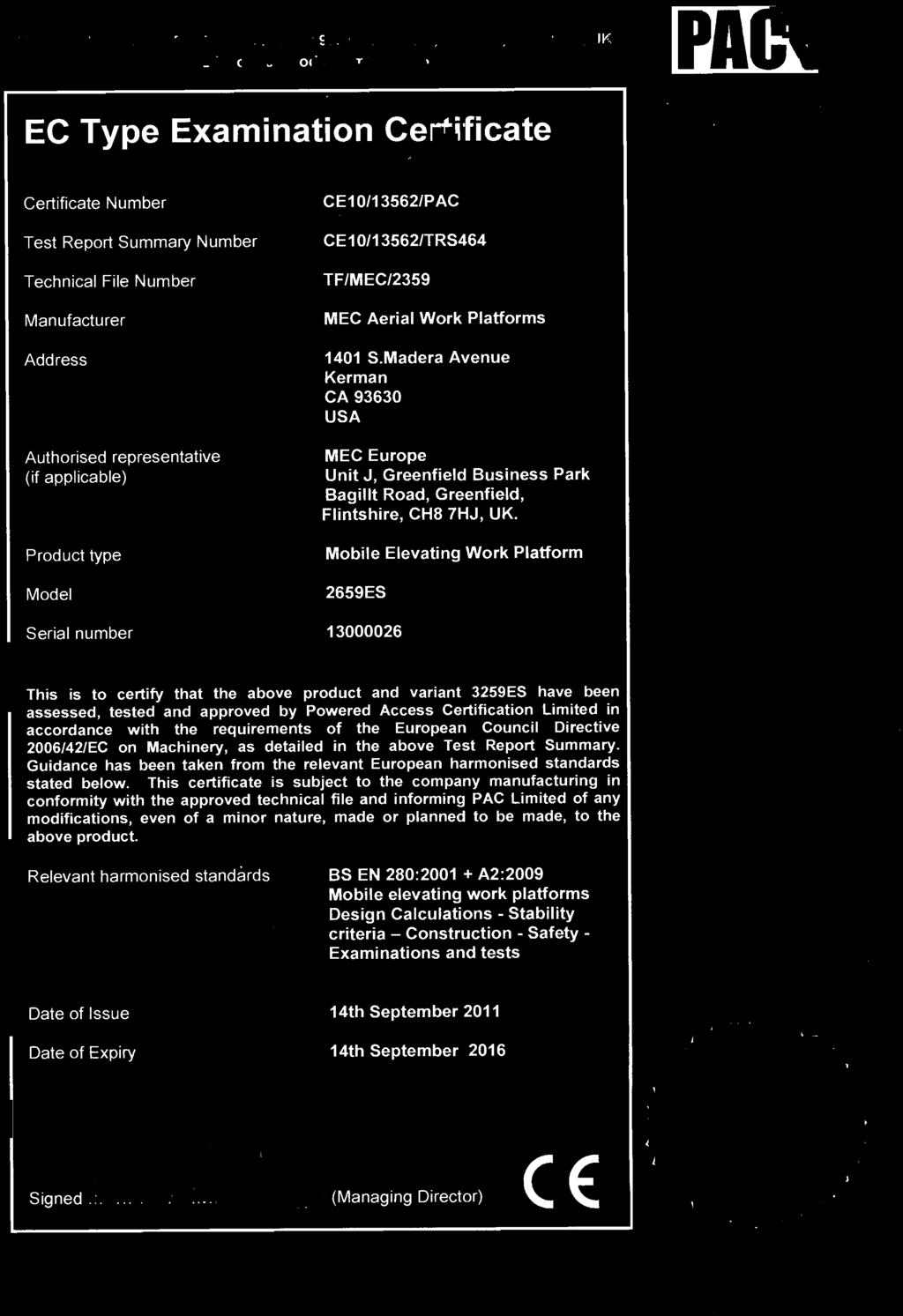
43 Transport and Lifting Instructions Aerial Work Platforms MEC AERIAL PLATFORM SALES CORP EC DECLARATION OF CONFORMITY Manufacturer: MEC AERIAL PLATFORM SALES CORP Address: 1401 South Madera, Avenue European Representative Kerman, CA Unit J, Greenfield Business Park USA Bagillt Road, Greenfield Flintshire CH8 7HJ UK Machine Type: Model No: Mobile Elevating Work Platform 2659ES, 3259ES Serial Number: Notified Body: Certificate No: Powered Access Certification Ltd Id #545 P O Box 98 Windermere, Cumbria LA23 1WF UK CE10/13562/PAC Applicable Harmonized Standards: EN280: A2:2009 We hereby declare that the above mentioned machine has been assessed, tested and approved in accordance with the requirements of the Machinery Directive 2006/42/EC using the document Guide to application of the Machinery Directive 2006/42/EC and taking guidance from EN 280: A2:2009. This Product also complies with the Following European Directives: EMC Directive 2004/108/EC Signed: Gary Crook Date: 24 August 2011 Names: Gary Crook Position: Director of New Product Development The above named person is empowered to sign on behalf of the above manufacturer. Any modification to the above-described machine violates the validity of this declaration Page 41 Novmber 23, 2011


44 Transport and Lifting Instructions Page Novmber 23, 2011
Operator s Manual. Crossover Series
 Operator s Manual ART_3812 2659ERT -- Serial #13000001 - Up 3259ERT -- Serial #13100001 - Up Specifications............................................ inside cover Introduction.......................................................
Operator s Manual. 92 Series Scissor Lifts 5492RT - Serial # Up 6092RT - Serial # Up
 Operator s Manual ART_3012 92 Series Scissor Lifts 5492RT - Serial #11900001 - Up 6092RT - Serial #12900001 - Up Introduction....................................................... 1 Safety..............................................................
Operator s Manual CE/Australian Specifications
 Operator s Manual CE/Australian Specifications Speed Level Sigma Lift - ES Models Serial Number 11700001 - up 91941 June 2010 Specifications......................................... inside cover Introduction....................................................
2591ES 3391ES 4191ES Scissor Lift 2591ES Serial # up 3391ES Serial # up 4191ES Serial # up
 ART_2849 2591ES 3391ES 4191ES Scissor Lift 2591ES Serial #11400001 up 3391ES Serial #11500001 up 4191ES Serial #11600001 up Introduction........................................... 1 Safety.................................................
Operator s Manual. CE/Australian Specifications. 60-J Diesel Boom Lift
 Operator s Manual CE/Australian Specifications 60-J Diesel Boom Lift Serial # 14400001 - Up Specifications............................................ inside cover Introduction.......................................................
Wind and Temperature Tip Over Hazard Do not add notice boards or similar
 Lift & Work Platform Safety Information Safety Information: Boom Lifts Safety Information: Scissor Lifts Safety Information: Boom Lifts Power Lines Electrocution Hazard Maintain safe clearance from Electrical
Operator's Manual GS -1530/32 GS -1930/32 GS GS GS GS GS GS with Maintenance Information
 GS -1530/32 GS -1930/32 GS -2032 GS -2632 GS -3232 GS -2046 GS -2646 GS -3246 CE with Maintenance Information Original Instructions Sixth Edition Second Printing Part No. 133568GT Front Matter Important
2047ES / 2647ES / 3247ES
 2047ES / 2647ES / 3247ES OPERATOR S MANUAL This Operator s Manual MUST BE READ AND UNDERSTOOD prior to operating your MEC Aerial Work Platform Part # 90908 Issued July 2005 Serial Number Range 3247ES:
OPERATOR S MANUAL. 3072ES 3772ES Electric Scissorlift. Specifications... 2 Introduction...3 Machine Components... 4 Machine Controls...
 15 OPERATOR S MANUAL 1775 Park Street, Suite 77 Selma, California 93662 Phone: (559) 891-2488 Fax: (559) 891-2493 3072ES 3772ES Electric Scissorlift Serial # 11201001 - Up Part # 91670 R1 June 2008 ART_2344
1532ES / 1932ES. OPERATOR S MANUAL This Operator s Manual MUST BE READ AND UNDERSTOOD prior to operating your MEC Aerial Work Platform
 1532ES / 1932ES OPERATOR S MANUAL This Operator s Manual MUST BE READ AND UNDERSTOOD prior to operating your MEC Aerial Work Platform Part # 90720 Rev A Issued May 2005 TABLE OF CONTENTS Introduction...
SELF-PROPELLED SCISSOR LIFTS OPERATOR S MANUAL. with Maintenance Information
 SELF-PROPELLED SCISSOR LIFTS OPERATOR S MANUAL with Maintenance Information ( For S0608EH, S0808EH, S08EH, S0EH, SEH, S4EH ) ( For S0608E, S0808E, S08E, S0E, SE, S4E ) ( Hydraulic Motor / DC Motor Drive
OPERATOR S MANUAL CE SPECIFICATIONS
 OPERATOR S MANUAL CE SPECIFICATIONS 1775 Park Street, Suite 77 Selma, California 93662 Phone: (559) 891-2488 Fax: (559) 891-2493 ART_2726 3072RT 3772RT 3772RT HD Scissorlift Serial # 3072RT: 9201000 -
Important. Contents. Contact us:
 Operator's Manual Sixth Edition First Printing Important Read, understand and obey these safety rules and operating instructions before operating this machine. Only trained and authorized personnel shall
Important. Contents. Contact us: First Edition Third Printing. Operator's Manual
 Operator's Manual First Edition Third Printing Important Read, understand and obey these safety rules and operating instructions before operating this machine. Only trained and authorized personnel shall
OPERATOR S MANUAL CE SPECIFICATION
 OPERATOR S MANUAL CE SPECIFICATION 3072ES / 3772ES 3772ES HD Electric Scissorlift Serial # 11201001 - Up Part # 91731 R1 ART_2498 Specifications... 2 Introduction...3 Machine Components... 4 Machine Controls...
OPERATOR S MANUAL. 3072RT 3772RT 3772RT HD Scissorlift. Specifications... 2 Introduction...3 Machine Components... 4 Machine Controls...
 1775 Park Street, Suite 77 Selma, California 93662 Phone: (559) 891-2488 Fax: (559) 891-2493 OPERATOR S MANUAL 1775 Park Street, Suite 77 Selma, California 93662 Phone: (559) 891-2488 Fax: (559) 891-2493
Operator s Manual QS-12W QS-15W QS-20W ANSI / CSA. with Maintenance Information. First Edition Second Printing Part No
 Operator s Manual QS-12W QS-15W QS-20W ANSI / CSA with Maintenance Information First Edition Second Printing Part No. 133494 First Edition Second Printing Important Read, understand and obey these safety
Table of Contents. GR-26J Part No Copyright 2010 by Terex Corporation
 Operator's Manual Third Edition First Printing Table of Contents Page Introduction... 1 Safety... 4 Symbol and Hazard Pictorials Definitions... 5 Personal Safety... 7 Work Area Safety... 8 Legend... 15
Important. Contents. Contact us:
 Operator's Manual Fourth Edition Third Printing Important Read, understand and obey these safety rules and operating instructions before operating this machine. Only trained and authorized personnel shall
Operator s Manual with Maintenance Information. Second Edition First Printing Part No
 with Maintenance Information Second Edition First Printing Part No. 82799 Second Edition First Printing Important Read, understand and obey these safety rules and operating instructions before operating
Important. Contents. Contact us:
 Operator s Manual Third Edition Fourth Printing Important Read, understand and obey these safety rules and operating instructions before operating this machine. Only trained and authorized personnel shall
Important. Contents. Contact us:
 Operator's Manual Third Edition Fourth Printing Important Read, understand and obey these safety rules and operating instructions before operating this machine. Only trained and authorized personnel shall
Operator s Manual. with Maintenance Information. CE Models. Second Edition Fifth Printing Part No
 Operator s Manual with Maintenance Information Second Edition Fifth Printing Part No. 82660 CE Models Operator's Manual Second Edition Fifth Printing Important Read, understand and obey these safety rules
Operator s Manual Z-45/25 Z-45/25J. DC Power Bi-Energy Power. ANSI/CSA North America South America Asia. AUS Australia. with Maintenance Information
 Operator s Manual Z-45/25 Z-45/25J DC Power Bi-Energy Power ANSI/CSA North America South America Asia AUS Australia with Maintenance Information Fourth Edition Second Printing Part No. 114344 Operator's
Important. Contents. Contact us:
 Operator's Manual Sixth Edition Third Printing Important Read, understand and obey these safety rules and operating instructions before operating this machine. Only trained and authorized personnel shall
Important. Contents. Contact us: Operator's Manual. Eighth Edition Third Printing
 Operator's Manual Eighth Edition Third Printing Important Read, understand and obey these safety rules and operating instructions before operating this machine. Only trained and authorized personnel shall
Important. Contents. Contact us:
 Operator's Manual First Edition Ninth Printing Important Read, understand and obey these safety rules and operating instructions before operating this machine. Only trained and authorized personnel shall
Operator s Manual with Maintenance Information. First Edition Sixth Printing Part No
 Operator s Manual with Maintenance Information First Edition Sixth Printing Part No. 72129 Operator's Manual First Edition Sixth Printing Important Read, understand and obey these safety rules and operating
Important. Contents. Contact us:
 Sixth Edition First Printing Important Read, understand and obey these safety rules and operating instructions before operating this machine. Only trained and authorized personnel shall be permitted to
Operator's Manual GS-2669RT GS-3369RT GS-4069RT. ANSI/CSA North America South America Asia. with Maintenance Information
 Operator's Manual Serial Number Range GS-2669RT GS-3369RT GS-4069RT from GS6911-101 ANSI/CSA North America South America Asia with Maintenance Information First Edition Third Printing Part No. 229831 Important
Important. Contents. Contact us:
 Operator's Manual Sixth Edition First Printing Important Read, understand and obey these safety rules and operating instructions before operating this machine. Only trained and authorized personnel shall
Operator s Manual with Maintenance Information. Third Edition Second Printing Part No
 Operator s Manual with Maintenance Information Third Edition Second Printing Part No. 97552 Operator's Manual Third Edition Second Printing Important Read, understand and obey these safety rules and operating
Important. Contents. Contact us:
 Operator's Manual Third Edition Third Printing Important Read, understand and obey these safety rules and operating instructions before operating this machine. Only trained and authorized personnel shall
Technical Publications IWP. Operator's Manual. Third Edition, First Printing Part No
 Technical Publications IWP Operator's Manual Third Edition, First Printing Part No. 35054 Operator s Manual Third Edition Important Read, understand and obey these safety rules and operating instructions
Operator's Manual SX-105 XC SX-125 XC. ANSI/CSA North America South America Asia. with Maintenance Information
 . Serial Number Range SX-105 XC SX-125 XC From SX105D-174 From SX125D-101 ANSI/CSA North America South America Asia with Maintenance Information First Edition Third Printing Part No. 1275466GT Front Matter
OPERATOR S MANUAL CE SPECIFICATIONS
 OPERATOR S MANUAL CE SPECIFICATIONS Specifications... 2 Introduction... 3 Machine Components... 4 Machine Controls... 6 Safety... 8 Safety Rules And Precautions... 8 Fall Protection Notice... 10 Safety
Operator's Manual. GS -1330m. AUS Australia. with Maintenance Information. First Edition First Printing Part No GT. Serial Number Range
 Serial Number Range GS -1330m GS30MD-101 AUS Australia with Maintenance Information First Edition First Printing Part No. 1295173GT Front Matter Contents Introduction... 1 Symbol and Hazard Pictorials
Important. Contents. Contact us:
 Operator's Manual Third Edition Fourth Printing Important Read, understand and obey these safety rules and operating instructions before operating this machine. Only trained and authorized personnel shall
Important. Contents. Contact us:
 Second Edition Fifth Printing Important Read, understand and obey these safety rules and operating instructions before operating this machine. Only trained and authorized personnel shall be permitted to
Operator Service Manual
 SELF-PROPELLED SCISSOR LIFTS Operator Service Manual S0608EH S0808EH S08EH S0EH Important Read, understand and obey these safety rules and operating instructions before operating this machine. Only trained
Operator's Manual GR-12 GR-15 GR-20. with Maintenance Information. Original Instructions Sixth Edition Third Printing Part No.
 Serial Number Range GR-12 GR-15 GR-20 from GR10-20000 from GRR-101 CE with Maintenance Information Original Instructions Sixth Edition Third Printing Part No. 133572 Front Matter Important Read, understand
Operator's Manual. Z-33/18 DC Power. Serial number range. From serial n.: Z331815M-101. with Maintenance Information
 . Operator's Manual Serial number range Z-33/18 DC Power From serial n.: Z331815M-101 CE with Maintenance Information Original Instructions First Edition First Printing Part No. 1257143 Operator's Manual
Operators manual Bumpa 8 metre 110v Bumpa 10 metre 110v
 Operators manual Bumpa 8 metre 110v Bumpa 10 metre 110v SAFETY RULES Mk3 Bumpa Conveyor Danger Failure to obey the instructions and safety rules in this manual will result in death or serious injury. Do
Technical Publications AWP. Operator's Manual. Fourth Edition, First Printing Part No
 Technical Publications AWP Operator's Manual Fourth Edition, First Printing Part No. 424 Operator s Manual Fourth Edition Important Read, understand and obey these safety rules and operating instructions
Operator s Manual. with Maintenance Information
 Before serial number Z30N-3448: Incorrect operation can result from use of this manual on machines that have not been updated according to Genie Campaign Bulletin 070001. Death or Serious Injury can result.
Operator s Manual. Z Z-45 25J IC Power. ANSI/CSA North America South America Asia. AUS Australia. with Maintenance Information
 Operator s Manual Z-45 25 Z-45 25J IC Power ANSI/CSA North America South America Asia AUS Australia with Maintenance Information Fourth Edition First Printing Part No. 114339 Operator's Manual Fourth Edition
Z Z Operator's Manual
 Technical Publications Incorrect operation can result from use of this manual on machines that have not been updated according to Genie Campaign Bulletin 070001. Death or Serious Injury can result. This
Operator s Manual Z-30 20N Z-30 20N RJ. with Maintenance Information. Original Instructions Fifth Edition Third Printing Part No.
 Operator s Manual Z-30 20N Z-30 20N RJ with Maintenance Information Original Instructions Fifth Edition Third Printing Part No. 133546 Important Read, understand and obey these safety rules and operating
Operator s Manual with Maintenance Information
 Operator s Manual with Maintenance Information Second Edition First Printing Part No. 82595 DC Power Operator's Manual Second Edition First Printing Important Read, understand and obey these safety rules
Operator s Manual. with Maintenance Information. First Edition Third Printing Part No
 Operator s Manual with Maintenance Information First Edition Third Printing Part No. 82800 Operator's Manual First Edition Third Printing Important Read, understand and obey these safety rules and operating
Operators manual Hoddi 6 metre 110v Bumpa 8 metre 110v Bumpa 10 metre 110v
 Operators manual Hoddi 6 metre 110v Bumpa 8 metre 110v Bumpa 10 metre 110v SAFETY RULES Mk3 Bumpa Conveyor Danger Failure to obey the instructions and safety rules in this manual will result in death or
Operator s Manual. with Maintenance Information. Fourt Edition First Printing Part No
 Operator s Manual with Maintenance Information Fourt Edition First Printing Part No. 1000189 Operator's Manual Fourt Edition First Printing Important Read, understand and obey these safety rules and operating
Operator's Manual S-40 S-45 ANSI/CSA. North America South America. Asia. with Maintenance Information. Sixth Edition First Printing Part No.
 ANSI/CSA S-40 North America South America S-45 Asia with Maintenance Information Sixth Edition First Printing Part No. 1259836 Front Matter Important Read, understand and obey these safety rules and operating
Important. Contents. Contact us: Operator's Manual. Eighth Edition Fifth Printing
 Operator's Manual Eighth Edition Fifth Printing Important Read, understand and obey these safety rules and operating instructions before operating this machine. Only trained and authorized personnel shall
Operator's Manual S-60 TRAX S-65 TRAX. AUS Australia. with Maintenance Information. Fourth Edition First Printing Part No
 S-60 TRAX AUS Australia S-65 TRAX with Maintenance Information Fourth Edition First Printing Part No. 1261732 Front Matter Contents Introduction... 1 Symbol and Hazard Pictorials Definitions... 4 General
Operator's Manual S-60X. ANSI/CSA North America South America Asia. with Maintenance Information. First Edition Fifth Printing Part No.
 Serial Number Range S-60X From S6010-21001 ANSI/CSA North America South America Asia with Maintenance Information First Edition Fifth Printing Part No. T107102 Front Matter Important Read, understand and
Operator s Manual. with Maintenance Information. Sixth Edition Second Printing Part No
 Operator s Manual with Maintenance Information Sixth Edition Second Printing Part No. 1000209 Operator's Manual Sixth Edition Second Printing Important Read, understand and obey these safety rules and
Operator's Manual S-65 TRAX. ANSI/CSA North America South America Asia. with Maintenance Information. Third Edition First Printing Part No.
 S-65 TRAX ANSI/CSA North America South America Asia with Maintenance Information Third Edition First Printing Part No. 1261731 Front Matter Contents Introduction... 1 Symbol and Hazard Pictorials Definitions...
Operator s Manual. with Maintenance Information. Third Edition Second Printing Part No
 Operator s Manual with Maintenance Information Third Edition Second Printing Part No. 110015 Bi-Energy IC Power Power Operator's Manual Third Edition Second Printing Important Read, understand and obey
SELF-PROPELLED SCISSOR LIFTS OPERATOR S MANUAL. with Maintenance Information DSL-40 WARNING
 SELF-PROPELLED SCISSOR LIFTS OPERATOR S MANUAL with Maintenance Information DSL-40 WARNING THE MANUFACTURER SHALL NOT BE HELD LIABLE IN CASE OF FAULTS OR ACCIDENTS DUE TO NEGLIGENCE, INCAPACITY, INSTALLATION
Operator s Manual. with Maintenance Information. Second Edition Second Printing Part No
 Operator s Manual with Maintenance Information Second Edition Second Printing Part No. 82599 Operator's Manual Second Edition Second Printing Important Read, understand and obey these safety rules and
Operator's Manual S-65. ANSI/CSA North America South America Asia. with Maintenance Information. Seventh Edition First Printing Part No.
 S-65 ANSI/CSA North America South America Asia with Maintenance Information Seventh Edition First Printing Part No. 1261728 Front Matter Contents Introduction... 1 Symbol and Hazard Pictorials Definitions...
Important. Contents. Contact us:
 Operator's Manual Seventh Edition Second Printing Important Read, understand and obey these safety rules and operating instructions before operating this machine. Only trained and authorized personnel
LKS300/LKS450 OPERATOR S MANUAL
 LKS300/LKS450 OPERATOR S MANUAL SAFETY RULES SHIFTA 300/450 Conveyor DANGER Failure to obey the instructions and safety rules in this manual will result in death or serious injury. Do Not Operate Unless:
Operator s Manual S-60 S-65. ANSI/CSA North America South America Asia. AUS Australia. with Maintenance Information
 Operator s Manual S-60 S-65 ANSI/CSA North America South America Asia AUS Australia with Maintenance Information Fifth Edition First Printing Part No. 114305 Operator's Manual Fifth Edition First Printing
Important. Contents. Contact us: Fifth Edition Third Printing. Operator's Manual
 Fifth Edition Third Printing Important Read, understand and obey these safety rules and operating instructions before operating this machine. Only trained and authorized personnel shall be permitted to
This lift will not operate with the generator engaged.
 WARNING 40' GENIE S40 PERSONNEL BOOM LIFT Any piece of equipment can be dangerous if not operated properly. YOU are responsible for the safe operation of this equipment. The operator must carefully read
Operator s Manual. with Maintenance Information. Fourth Edition Third Printing Part No
 Operator s Manual with Maintenance Information Fourth Edition Third Printing Part No. 82580 Operator's Manual Fourth Edition Third Printing Important Read, understand and obey these safety rules and operating
Hy-Brid Lifts HB-P827 HB-P1027 SERIES 1 MAINTENANCE & TROUBLESHOOTING PUSH-AROUND AERIAL WORK PLATFORM. Part NO. SUPO-670 May 2014
 MAINTENANCE & TROUBLESHOOTING PUSH-AROUND AERIAL WORK PLATFORM Part NO. SUPO-670 May 2014 HB-P827 HB-P1027 SERIES 1 NOTES If there is a question about application and/or operation, contact: CUSTOM EQUIPMENT,
Operator s Manual with Maintenance Information. First Edition Fifth Printing Part No
 Operator s Manual with Maintenance Information First Edition Fifth Printing Part No. 52630 Operator's Manual First Edition Fifth Printing Important Read, understand and obey these safety rules and operating
Important. Contents. Contact us:
 Operator's Manual Fifth Edition Second Printing Important Read, understand and obey these safety rules and operating instructions before operating this machine. Only trained and authorized personnel shall
SERVICE AND PARTS MANUAL. Micro 19. Serial Number Range Up
 SERVICE AND PARTS MANUAL Micro 19 Serial Number Range 16900000 - Up Part # 94554r1 Revision History Original Release Date: Date Reason for Update New Release Aerial Platform Sales Corp. 1401 S. Madera
Operator s Manual with Maintenance Information. Second Edition Third Printing Part No
 Operator s Manual with Maintenance Information Second Edition Third Printing Part No. 82233 Operator's Manual Second Edition Third Printing Important Read, understand and obey these safety rules and operating
Grease Stand MODEL# DF MAINTENANCE AND OPERATION MANUAL. Page 1
 Grease Stand Page 1 WARNING Safety First Standards Tested in general accordance with the applicable requirements of DIN EN 131 2 : 2012 BS EN 131 7 : 2013 ANSI ASC A147 20 2011 The best insurance against
Maintenance and Operation Manual for Landing Gear Access Stand
 Maintenance and Operation Manual for Landing Gear Access Stand DF071592 03 Liftsafe Fall Protection Inc. Landing Gear Access Stand Manual Page 1 Table of Contents Section Page Number 1.0 Standards 3 2.0
PLATFORM WHEEL WELL ACCESS STAND
 PLATFORM WHEEL WELL ACCESS STAND Page 1 Standards WARNING Safety First Tested in general accordance with the applicable requirements of DIN EN 131 2 : 2012 BS EN 131 7 : 2013 ANSI ASC A14.7 20 2011 The
Operator s Manual. with Maintenance Information. Second Edition Ninth Printing Part No from 832 to 7189
 Operator s Manual with Maintenance Information Second Edition Ninth Printing Part No. 43645 from 832 to 7189 Operator's Manual Second Edition Ninth Printing Important Read, understand and obey these safety
Operator s Manual with Maintenance Information
 Operator s Manual with Maintenance Information FourthEdition FirstPrinting Part No.97866 This manual replaces partnumber 72895 Fourth Edition First Printing Important Read, understand and obey these safety
BY CUSTOM EQUIPMENT LLC OPERATIONS & SAFETY MANUAL PUSH-AROUND AERIAL WORK PLATFORM SUPO-642E REV D HB-P3.6 SERIES I
 MANUAL PUSH-AROUND AERIAL WORK PLATFORM SERIES I NOTES If there is a question about application and/or operation, contact: Custom Equipment, LLC 2647 Hwy 175 Richfield, WI 53076 U.S.A. P: +1-262-644-1300
Operation Service Parts Manual MVFP016E
 Operation Service Parts Manual MVFP016E Important Read, understand and obey these safety rules and operating instructions before operating this machine. Only trained and authorized personnel shall be permitted
Genie North America. Important. Genie Europe. Contents
 Operator s Manual Sixth Edition Important Read, understand and obey these safety rules and operating instructions before operating this machine. Only trained and authorized personnel shall be permitted
Operator s Manual with Maintenance Information
 Operator s Manual with Maintenance Information Second Third Edition Seventh First Printing Printing Part No. 43645 97780 Operator's Manual Third Edition First Printing Important Read, understand and obey
Operator s Manual with Maintenance Information. Second Edition Sixth Printing Part No
 Operator s Manual with Maintenance Information Second Edition Sixth Printing Part No. 43655 Operator's Manual Second Edition Sixth Printing Important Read, understand and obey these safety rules and operating
X X26 Serial Numbers
 X 26-32 X26 Serial Numbers 50906 53100 ENGLISH When contacting Upright for service or parts information, be sure to include the MODEL and SERIAL NUMBERS from the equipment nameplate. Should the nameplate
Operator's Manual TZ-50. AUS Australia. with Maintenance Information. Fourth Edition Third Printing Part No
 TZ-50 AUS Australia with Maintenance Information Fourth Edition Third Printing Part No. 227344 Front Matter Important Read, understand and obey these safety rules and operating instructions before operating
Operator s Manual. with Maintenance Information. Original Instructions Fourth Edition Fourth Printing Part No
 with Maintenance Information Original Instructions Fourth Edition Fourth Printing Part No. 145356 Fourth Edition Fourth Printing Important Read, understand and obey these safety rules and operating instructions
SERVICE AND PARTS MANUAL 1330SE. Serial Number Range Up. ART_4907a
 SERVICE AND PARTS MANUAL 1330SE ART_4907a Serial Number Range 16300001 - Up Part # 94123r2 Revision History Original Release Date: June 2016 Date June 2016 Reason for Update New Release New Style Ground
Operator s Manual with Maintenance Information
 Operator s Manual with Maintenance Information Second Third Edition Seventh First Printing Printing Part No. 43645 133555 Operator's Manual Third Edition First Printing Important Read, understand and obey
Important. Contents. Contact us:
 Operator s Manual Third Edition Sixth Printing Important Read, understand and obey these safety rules and operating instructions before operating this machine. Only trained and authorized personnel shall
Important. Contents. Contact us:
 Operator s Manual Third Edition Third Printing Important Read, understand and obey these safety rules and operating instructions before operating this machine. Only trained and authorized personnel shall
WARNING. The MX19 Machine has been re-assessed to ensure compliance to the Machinery Directive (2006/42/EC).
.") WARNING The MX19 Machine has been re-assessed to ensure compliance to the Machinery Directive (2006/42/EC). The Machine rating has been changed from: Windspeed rating of 12.5 m/s (Beaufort 6) To Windspeed
WARNING The MX19 Machine has been re-assessed to ensure compliance to the Machinery Directive (2006/42/EC). The Machine rating has been changed from: Windspeed rating of 12.5 m/s (Beaufort 6) To Windspeed
Ground Controls. Cage Control Levers. 1) Cage/Platform 2) Cage Controls 3) Ground Controls Buttons. Ground Control Levers
 Cage/Platform 2) Cage Controls 3) Ground Controls Buttons. Ground Control Levers") P14936/01 P14939/01 1 2 3 4 5 6 Nifty HR12 (12082) 1) Cage/Platform 2) Cage Controls 3) Ground Controls Buttons 4) Ground Controls - Levers 5) Lower 6) Upper 7) Cage/Ground Selector 8) Manual Hand Pump
P14936/01 P14939/01 1 2 3 4 5 6 Nifty HR12 (12082) 1) Cage/Platform 2) Cage Controls 3) Ground Controls Buttons 4) Ground Controls - Levers 5) Lower 6) Upper 7) Cage/Ground Selector 8) Manual Hand Pump
GUIDELINES FOR THE USE OF SCISSOR LIFTS (ELEVATING WORK PLATFORMS) AND AERIAL BOOM LIFTS (EXTENSIBLE BOOM PLATFORMS)
 AND AERIAL BOOM LIFTS (EXTENSIBLE BOOM PLATFORMS)") Building for Tomorrow s Leaders LACCD Program Management 1055 Corporate Center Drive Monterey Park, California 91754 www.build-laccd.org 323.981.7200 tel BuildSafe Safety Bulletin for April 2018 GUIDELINES
Building for Tomorrow s Leaders LACCD Program Management 1055 Corporate Center Drive Monterey Park, California 91754 www.build-laccd.org 323.981.7200 tel BuildSafe Safety Bulletin for April 2018 GUIDELINES
Operator's Manual Z -45 XC. ANSI/CSA North America South America Asia. with Maintenance Information. First Edition Second Printing Part No.
 Z -45 XC ANSI/CSA North America South America Asia with Maintenance Information First Edition Second Printing Part No. 1290304GT Front Matter Contents Introduction...1 Symbol and Hazard Pictorials Definitions...5
shortform operating instructions
 0800 52 15 95 www.facelift.co.uk UpRight sl20 shortform operating instructions scissor lifts This book is designed as a guide to enable you to start work quickly and safely. It is not intended to replace
before serial number 2214
 before serial number 2214 Contents Page Safety Rules... 3 Pre-operational & Safety Inspection... 4 Operating Instructions... 6 Transport... 12 Maintenance & Routine Service... 12 Specifications... 14 SAFETY
Important. Contents. Contact us:
 Operator's Manual Second Edition First Printing Important Read, understand and obey these safety rules and operating instructions before operating this machine. Only trained and authorized personnel shall
SECTION 14: AERIAL LIFT PROGRAM
 SECTION 14: AERIAL LIFT PROGRAM Fisher Auto Parts is committed to promoting a safe and healthy environment for all employees and customers. Protection from accidental loss of any resources, especially
Operator s Manual with Maintenance Information. Distributed By: This manual replaces part number Towing Checklist (Use at each stop)
") Towing Checklist (Use at each stop) Genie North America Phone 425.881.1800 Toll Free USA and Canada 800.536.1800 Fax 425.883.3475 Genie Australia Pty Ltd. Phone + 61 7 3375 1660 Fax + 61 7 3375 1002 Genie
Towing Checklist (Use at each stop) Genie North America Phone 425.881.1800 Toll Free USA and Canada 800.536.1800 Fax 425.883.3475 Genie Australia Pty Ltd. Phone + 61 7 3375 1660 Fax + 61 7 3375 1002 Genie
Operator s Manual Part Number EE July, 2005
 Operator tor s Manual Part Number 0361518EE July, 2005 The aerial platform is not electrically insulated. Death or serious injury will result from contact with, or inadequate clearance from, an energized