Officially licensed product
|
|
|
- Meghan Robbins
- 6 years ago
- Views:
Transcription


1 Officially licensed product


 29 55 / 76 03-33 E-Mail:")


2 Copyright: 2015 / ViewApp Software Applications & design e.u. Project Management & Development: Official Website: Daniel Buda (Engineer) MANUAL Copyright: 2015 / Aerosoft GmbH Flughafen Paderborn/Lippstadt D Bueren, Germany Tel: +49 (0) / Fax: +49 (0) / Internet: info@aerosoft.com All trademarks and brand names are trademarks or registered trademarks of their respective owners. All copyright and intellectual property rights reserved. Add-On for OMSI 2 - The Omnibus Simulator 2 3
3 Content Introduction... 5 System Requirements... 5 Installation... 6 Aerosoft Launcher... 7 Removal Setting options for this Add-On in OMSI About this manual The Route The Vehicles Preparing to drive your route Hints for driving the Vienna Bus Line Your First Bus Trip: A Quick Start Guide LU 200 Bus Functions in Detail NL 205 Bus Functions in Detail Other Devices on the Vehicle Conduct During Operation Bus Traffic Signals Credits Introduction Welcome to Vienna! Vienna is a city with a long history and tradition, historic buildings, endless leisure activities and excellent local public transportation. This Add-On is an expansion for OMSI, in which you serve the public as a bus driver on the fabulous 24A line. This authentic and realistic Add-On is modeled on the route of the 24A line as it developed over time we guarantee a lot of variety and fun! Go back to 2005 and 2006 when the bus line moved from the last generation of high-floor buses to the new generation of low-floor models. You will take the wheel of the LU 200 or the NL 205 model of the Wiener Linien and transport passengers safely to their destination. System Requirements In order for the Vienna 1 - Line 24A Add-On to play as smoothly as possible, your system should have the following minimum requirements: OMSI 2 The Omnibus Simulator min Operating system: Microsoft Win XP / Vista / 7 / 8 / 8.1 Processor (CPU): 2,6 GHz Dual-Core Memory: 4 GB RAM Free disk space: 6 GB Graphic card with 1024 MB (DirectX: 9.0 or higher) Internet connection and Steam user account. A minimum age of 13 is required to create a user account with Steam. Please note: A Steam internet connection is required for the online activation. 4 5
4 Recommended Equipment Processor: 3.2 GHz Quad Core Memory: 8 GB 3D graphics card with a minimum of 2 GB of graphics memory Force Feedback steering wheel (best with 900 angle of rotation) Installation You have to be logged in with administrator rights before you start the installation of OMSI 2 Add-On Vienna 1 - Line 24A. To start the installation simply insert the DVD into your DVD drive or run the file you downloaded from your shop account. After you have chosen your preferred installation language, the welcome screen appears and you will be presented with some important information and the license agreement. Please read it carefully. The installation program will attempt to locate the correct path. If you wish to install to another location, then you will have to enter the correct path for installation manually. In order to do this, click on Browse and navigate to the correct path. Before the installationprogram starts to copy the files onto your hard disc, you will be presented with all the installation details. The installation program will now copy all of the OMSI 2 - The Omnibus Simulator files onto your hard disk. If you want to make any changes or to install any updates for this program you will need the DVD or the installation file from the download shop and your registration key again. Important note! Subsequent to the installation the Aerosoft-Launcher will be started for the online registration. Learn more about this program in the next chapter. Aerosoft Launcher General information about the Aerosoft-Launcher The Aerosoft-Launcher gives you an overview of all Aerosoft products installed on your computer. You will also have easy access to special features available for the several products. Should the SOFTWARE PRODUCT require an Online Registration, the Aerosoft LAUNCHER will take you through this process. The Aerosoft- LAUNCHER will be automatically installed with the SOFTWARE PRODUCT and will launch at the end of the install process. You can run the Aerosoft-Launcher at any time via the Windows START menu to check the activation state of your installed SOFTWARE PRODUCTS. Just follow this link: START ALL PROGRAMS AEROSOFT Aerosoft Launcher The Aerosoft-Launcher starts up in the Library view by default. Here you can see an overview of all installed Aerosoft SOFTWARE PRODUCTS and their state of activation. The following categories will be shown. Aircraft, Sceneries, Tools/Missions, Category-Unknown and Simulation. The SOFTWARE PRODUCT will be placed in one of these categories accordingly during installation. Older SOFTWARE PRODUCTS which do not need an online activation will be placed in the category Category-Unknown. In the Library view you will also see an overview of current Aerosoft News. 6 7

5 What is required for an installation? For an installation and an online activation you will have to have administrator rights. Please make sure that you have these rights. You will also need an active internet connection. How do I activate a SOFTWARE PRODUCT? If necessary please change to the Library view and select the SOFTWARE PRODUCT for activation. Click on the button activate.the following screen will appear: Please enter your address and your registration key correctly and click on Online activation. You will need an active internet connection for this procedure. You registration data will transfered to our Aerosoft server now. Your information will now be transferred to the Aerosoft server. After a successful transfer your system will be activated and used without further limitations. Please note that depending on the safety settings some data of theaerosoft SOFTWARE PRODUCT need to be personalized. Information about the activation status GREY == undefined GREEN == active YELLOW == reactivation required RED == activation unsuccessful I want to install the SOFTWARE PRODUCT again. How do I do this? The Library view will show the activation status of each SOFTWARE PRODUCT. If it is shown in GREEN, the SOFTWARE PRODUCTS are active. A new activation is not necessary. If it shows YELLOW the SOFTWARE PRODUCTS have at least been activated once but need a new online activation because of new hardware in your system. Click on the button activate. Please note that all required information has been correctly filled in. There is an update available for the SOFTWARE PRODUCT. Does it change the activation status? Normally the activation status will not be changed. It is possible though that an adoption of the activation status on to the new installed data is necessary. If this is the case change to the Library view and select the appropriate SOFTWARE PRODUCT. Click on the refresh Button to take over the activation status. I have to reconfigure my PC-System or I have got a new PC. What do I have to bear in mind? A check of the activation keys commences every time the Aerosoft- LAUNCHER is started. Depending on the activation status, a new activation might be necessary. 8 9
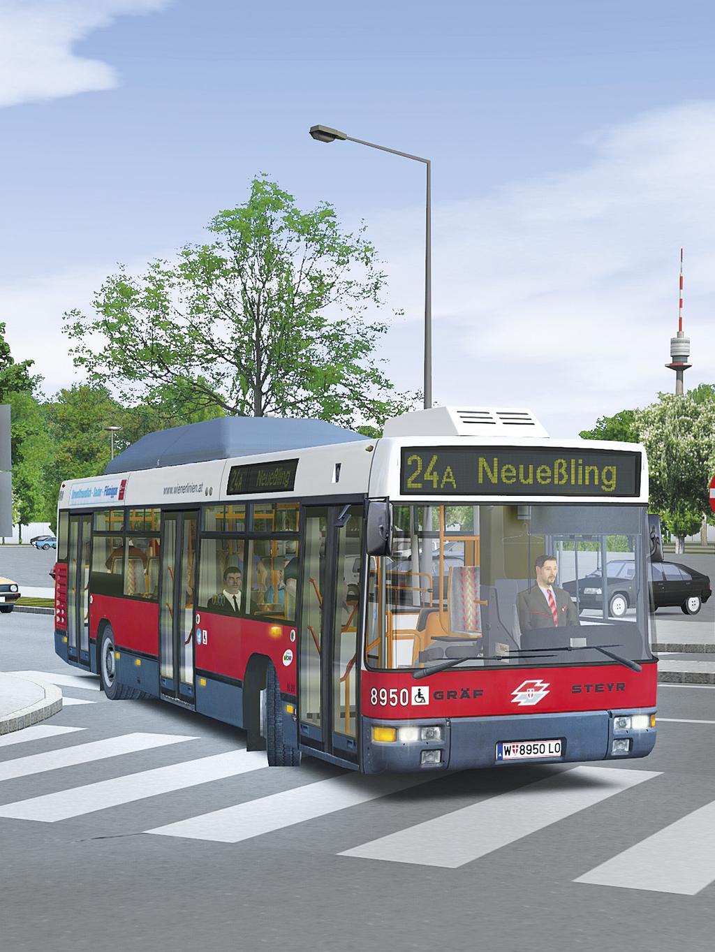
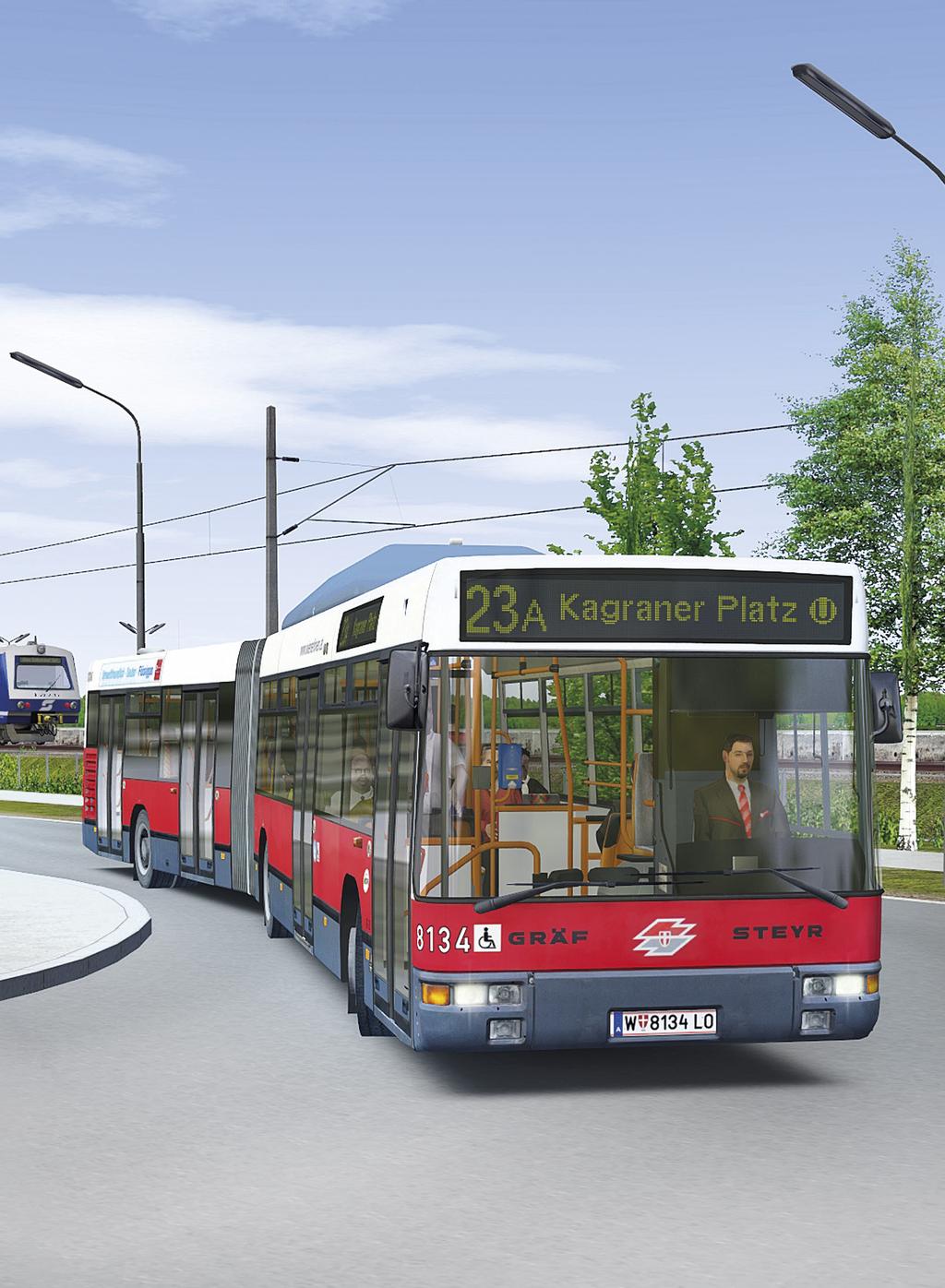
6 Removal In order to fully remove OMSI 2 Add-On Vienna 1 - Line 24A run the Aerosoft-Launcher. Change to the Library and select OMSI 2 Add-On Vienna 1 - Line 24A in the Simulation category. The information about OMSI 2 Add-On Vienna 1 - Line 24A will appear. Click on the Uninstall button. The installation program will start to remove the program from your hard disk. Setting options for this Add-On in OMSI The following settings are recommended for this Add-On to perform optimally in OMSI. Please go to the menu options and set the options as listed below: Graphic: Number of neighbor tiles 3 Expanded graphics: Sound: Use only low-resolution textures: No Set maximum memory requirements for high-resolution. Textures: 1024 MB Texture size real-time textures: 512 Maximum sound level: 1000 Area Transport: Schedule-priority: 4 Reduced use AI-list: No About this manual This manual is limited to describing and explaining this Add-On. It is a supplement to the manual for the main game OMSI 2 - The Omnibus Simulator. The basic function descriptions and instructions for operation and configuration of OMSI simulation are in the OMSI manual. This Add-On manual uses explicit references to the OMSI handbook to provide clarification and optimal guidance. If you have already installed and played the main game OMSI 2 - The Omnibus Simulator, you should not have to make any changes to the settings. This Add-On product was designed to work with the main game and can be played with the standard configurations. The Route With this Add-On you plunge right into the action on the 24A Line in Vienna s 22nd district, Donaustadt. The 24A Line is varied and beautiful. The route changed over time to adapt to transportation policies. The original route started in the Kagran center, one of the most important hubs in the district for connections to other bus and tram lines, and the U1 subway terminus. In 2006, the U1 subway line was extended from Kagran to Leopoldau, changing the line gradients on the street surface. The high-floor and low-floor buses, operated by the Vorgarten service garage, were in the last years of mixed-mode operation. As part of the September 2006 extension of the U1, the 24A bus line was reduced in Kagraner square and the buses were completely switched to low-floor models. At the same time the buses were added to the RBL line, the computer-controlled train system

7 The 24A line leads from the heart of the district to the outskirts in Neueßling and on to Invalidensiedlung. You ll quickly find that the mixture of tight, close city streets and idyllic outskirts flanked by fields makes this line uniquely attractive and challenging. This Add-On offers 3 lines, as well as a few routes that operate on a limited schedule and provide interesting changes to the route. The main routes of the 24A line are: Kagraner Platz (U) Breitenlee School Kagraner Platz (U) Neueßling Kagraner Platz (U) Invalidensiedlung In addition, the following routes run on a limited schedule: Trips across Breitenlee Nebenfahrbahn The Algenweg - Huflattichweg Daphneweg loop Routes over Breitenlee in the morning and to Breitenlee School at noon This line is operated with two different types of buses: LU 200, the last of the high-floor generation in Vienna NL 205, the first of the low-floor generation in Vienna The Vehicles LU 200 M11 The LU 200 M11 is an 11-meter long bus with a 200 hp engine under the floor. It is built with special Austrian construction by the ÖAF-Gräf & Stift and Steyr-Daimler-Puch companies for the Vienna Public Transport. The body is similar to the German VÖV standard city buses, but has a third entrance door in the rear in accordance with Vienna standards. (The VÖV is the German insurance standards association.) The bus engine runs on gasoline. The LU 200 was by far the most numerous of the bus models in the history of Wiener Linien, with 345 buses purchased between 1978 and The last scheduled use of an LU 200 on regular Wiener Linien service took place on May 21, The very last LU 200 was used as a school bus in its last years of operation. It was decommissioned on March 9, 2009 after almost 30 years of service in the Wiener Linien
")
8 Technical data: Length Width Height Wheelbase 11.5 meters 2.5 meters meters 5.6 meters NL 205 M12 Motor Cubic capacity Gearbox Highest speed Fuel Tank Gas needed for 100km Empty weight Maximum weight allowed Seats 31 Standing room 58 MAN G2566, 147kw with 2100 U/min (200 PS) ccm, Hub: 155 mm Voith D km/h LPG gasoline 3x120 (96), 2x89 (71.2) liter About 110 liters 9840 kg 16,000 kg The NL 205 M12 is a 12-meter long, 205 HP, low-floor model bus. It is built with special Austrian construction by the ÖAF-Gräf & Stift and Steyr-Daimler-Puch companies for the Vienna Public Transport. The story of this model goes further back than many would suspect. At the end of 1988, 70 of the last 200 model LU buses were still in production, when the Vienna Public Transport contracted Gräf & Stift and Steyr to design a new type of vehicle, which enabled the first stepless entry, the low-floor model in use today. Design and model studies followed and finally, in 1991, two Gräf / Steyr M12 NL 205 prototypes were designed and in 1992, testing began. Compared to the previous LU 200, the new model incorporated many revolutionary changes. In addition to the electronic destination display on the outside and the stop display inside the bus, the seats were upholstered. The gas tanks, which had been under the bus in the high-floor models like the LU 200, were moved to the roof to accommodate the low-floor construction and were hidden under a protective cover. These developments were later incorporated into German vehicle production. In 1994, the first of the NL 205 M12 models were put into service
9 One of the special features of this generation of vehicles was the air conditioning built into some of the models. In 1997, air conditioning became standard equipment in all vehicles. In 1998, manually operated folding ramps were tested successfully. Thereafter, all new vehicles incorporated these ramps while older models were retrofitted. In 1999, the Steyr plant in Vienna closed, and thus ended the production of the NL 205. The last scheduled deployment of the NL 205 for regular services on the Wiener Linien took place on June 27, Currently there are eight NL 205 vehicles used as buses for the driving school of the Wiener Linien, as well as one converted NL 205 Infobus. Technical data: Empty weight 11,330 kg Maximum weight allowed 18,000 kg Seats 27 Standing room 58 Length Width Height Wheelbase meters 2.5 meters 3.34 meters 5.88 meters Motor Cubic capacity MAN G2866 DUH, 151kw with 2100 U/min (205 PS) ccm Gears Voith D851.2 Highest speed 80 km/h Fuel Tank Gas needed for 100km LPG gasoline (60% propane, 40% butane) 3x 200 liter About 100 liters 16 17

10 Preparing to drive your route To successfully master your first day as a bus driver, you should familiarize yourself with the technical specifications. If you re not very familiar with OMSI, we recommend you to read Chapter 2 of the OMSI manual. Starting the Add-On: The first time you start, please choose from the options map without buses. You can still set a desired date and time, press the Start! button and you re on your way! Hints for driving the Vienna Bus Line The main functions and key commands for controlling the Vienna buses is the same as that of the buses in the main OMSI game. The Add-On was created with ease of setup and compatibility in mind, so the keyboard layout and peripheral settings such as the steering wheel can remain as configured for the main OMSI game. This means that a majority of the keyboard shortcuts from the OMSI will apply to the Vienna line. Only the door control and operation of loud speaker control on the IBIS instruments are different. These are described separately. Your First Bus Trip: A Quick Start Guide Once you have selected your bus from the menu and placed it at an entry point on the map (see Section 2.6 in OMSI manual), an introduction to the bus functions begins. With Quick Start you have an overview of the most important functions on the two buses allowing you to get under way: We have created two routes for the Route 24A line. Please select the appropriate version from the menu above: Vienna 1 - Line 24A /2005 Kagran (U) Invalidensiedlung Route A schedule with mixed operation of high-floor and low-floor buses Vienna 1 - Line 24A /2006 Kagraner Platz (U) Invalidensiedlung Route A schedule with low-floor buses 18 19


![Step 1: Turn on the electricity by pressing the [E] key, or click on the master battery key (1) with your mouse.](/docs-images/74/70793074/images/11-4.jpg "NOTE: The 2 and S must briefly light up to confirm the correct number of axels.")

11 Quick Start Guide: LU 200 Step 2: Click on 2 to activate the voice control unit. You can see that the announcements are activated and the number 1 button lights up. Step 3: Check the GoBox before and after each journey by clicking on the button. When you first board the LU 200, no indicator lights are illuminated and many functions with closed circuit current are not yet working. Step 1: Turn on the electricity by pressing the [E] key, or click on the master battery key (1) with your mouse. NOTE: The 2 and S must briefly light up to confirm the correct number of axels. Step 4: Turn on the ignition by pressing the M key or clicking the ignition key (3). NOTE: Only Door 1 can be opened without the master battery key by using sufficient compressed air, either by pushing the button on the driver s control panel or via a pin through the door opener at the nose of the vehicle. A few control lights will turn on. NOTE: More lights will illuminate. Step 5: Start the engine by pressing the M key again or clicking the ignition key (3). NOTE: It is only possible to start if the gear selector is in neutral! Step 6: Wait for the pressure to build. The red warning light will go out


![Step 8: Engage the gears by pressing the [D] key.](/docs-images/74/70793074/images/12-3.jpg "Step 1: Activate the electric and gas switches by pressing the [E] key, or by clicking the battery master switch (1) and gas system switch (3) with the mouse.")
![Step 9: Release the parking brake by pressing the [.]. IMPORTANT: Always activate the parking brake (the hand brake) as soon as the bus has stopped or when at a standstill!](/docs-images/74/70793074/images/12-4.jpg "We recommend you use the parking brake when you re stopped at a long red light and do not want to permanently press on the brake pedal.")
12 Watch the white hands of the two double-gauges in the center of the dashboard: They should exceed 6. NOTE: The operating pressure in the compressed air system must high enough for the brakes, air suspension and doors to work properly. Filling the compressed air system can take 1-2 minutes to complete. Step 7: Choose the line and destination (via the menu). Quick Start Guide NL 205 When you first board the NL 205, no indicator lights are illuminated and many functions with closed circuit current are not yet working. Step 8: Engage the gears by pressing the [D] key. Step 1: Activate the electric and gas switches by pressing the [E] key, or by clicking the battery master switch (1) and gas system switch (3) with the mouse. Step 9: Release the parking brake by pressing the [.]. IMPORTANT: Always activate the parking brake (the hand brake) as soon as the bus has stopped or when at a standstill! We recommend you use the parking brake when you re stopped at a long red light and do not want to permanently press on the brake pedal. NOTE: Only Door 1 can be opened without the master battery switch by using sufficient compressed air, either by pushing the button on the driver s control panel or via a pin through the door opener at the nose of the vehicle. If the switch is turned off for the gas system, the connection to the gas tank is interrupted and the engine cannot be started. A few control lights will turn on. Step 2: Click on 2 to activate the voice control unit. You can see that the announcements are activated and the number 1 button lights up
.")

. Step 8: Engage the gears by pressing the [D] key. Step 5: Start the engine by pressing the M key again or clicking the ignition key (4).")
 as soon as the bus has stopped or when at a standstill!")
13 Step 3: Check the GoBox before and after each journey by clicking on the button. NOTE: The 2 and S must briefly light up to confirm the correct number of axels. Step 4: Turn on the ignition by pressing the M key or clicking the ignition key (4). Watch the orange lights for the compressed air pressure gauge on the left of the speedometer, as well as the two red warning lights (= central warning lights) at the top. These indicate that the bus is not yet ready. These lights will extinguish when the pressure has reached 6 - then the bus is operational. NOTE: The pressure in the compressed air system must high enough for the brakes, air suspension and doors to work properly. Filling the compressed air system can take 1-2 minutes to complete. Step 7: Choose the line and destination (via the menu). Step 8: Engage the gears by pressing the [D] key. Step 5: Start the engine by pressing the M key again or clicking the ignition key (4). Turn until it the engine catches. NOTE: It is only possible to start if the gear selector is in neutral, N! Step 6: Wait for the pressure to build. The red warning light will go out. Step 9: Release the parking brake by pressing the [.] IMPORTANT: Always activate the parking brake (the hand brake) as soon as the bus has stopped or when at a standstill! We recommend you use the parking brake when you re stopped at a long red light and do not want to continuously press on the brake pedal. In addition, the NL 205 leveling mechanism is activated by pressing the parking brake - use this whenever you need to change the level of the bus
 5.")
14 LU 200 Bus Functions in Detail Overview of the Driver s Controls Below you ll find a detailed description and overview of the driver s controls for the Vienna Line s LU 200 M11 model: 1. Parking Brake Light 2. Central Warning Light the vehicle cannot be driven. Stop immediately! 3. Fuel Gauge 4. Fuel Tank Selection Switch (does not function) 5. Door Controls (this is explained below in detail) 6. Turn Signal Lever 7. Windshield Wiper Lever 8. Speedometer in km/h with clock 9. Odometer (set when adding the bus, taking into account average mileage and model year of the current year in OMSI using a plausible baseline). Make note in mileage book before departure. 10. Toggle Switches from Left to Right: Rear Fog Light Roof Vent (essential only in summer) Passenger area heating Fog Lights Route Indicator Light (Display) Blue Route Light indicator (formerly used for signaling the last trip before closing, it has not been operated for some years) 11. Warning Light 12. Battery Key 13. Ignition/Start key 14. Gear selection: Important - there can be only one active button! The middle position D is Drive. The left position is particularly useful when driving uphill, because only the first two gears are engaged. The vehicle is in neutral when none of the three keys is pressed. To release a button, press it a second time. The right button is for reverse. Confirm reverse after shifting by pressing R-free (15). Only then is the reverse gear engaged. There is a distinctive sound when shifting into reverse. 15. R-free Button 16. Announcement Control Unit: Information stored in the respective coding card is displayed on this unit and indexed accordingly. The top number indicates the direction of travel and the numbers underneath show the next leg of the trip and corresponding stop. You can find a list of this in the appendix. 17. Double gauge: The LU200 has two brake circuits. The orange hand points to the current brake pressure (for example 0 bar or atmospheres when the brake is not active). The white hand points to the reservoir pressure in the corresponding air reservoir. To test: Press the brakes when the motor is disengaged. The brake pressure rises sharply; however, the reservoir pressure falls. Only when the engine is running will this fill up again. The parking brake and door control system use the air pressure from the respective tanks. This is why the doors work very slowly or not at all with too little air supply. 18. Double-Gauge Rear Axle 19. Coolant temperature: Measures whether the engine is too cold or too hot. 20. High Beams 21. Battery Light 22. Temperature Control Indicator (does not function) 23. Ignition Light 24. Blinker Light 25. Oil Pressure Light 26. Catalytic Converter Warning Light 27. Anti-Lock Brake Light 26 27

15 Door Control Panel 1. Release button: Press this button when you load passengers at the bus stop. Press the button to enable doors to open when a passenger has made a stop request, or to enable the open door buttons on the outside of the bus that allow passengers at the bus stop to open the doors. The blue Release button is illuminated while it is active. Key: [NUM /] 2. Clear Release button: As long as Release is enabled, all the doors (except for Door 1) are on automatic. Passengers can open doors and doors will close after a delay when no passenger is in the photoelectric field. Since Door 1 has no light barrier and is monitored by the bus driver, the driver must manually open and close the door (see below). By pressing the Clear Release button you deactivate the automatic mode. The lights on the release button extinguish. Once all doors are closed (regardless whether the release is active or not), the green Departure signal will light up (see below) and a Gong is heard, signaling the driver that the bus is ready to proceed. NOTE: The hand brake releases immediately when the Clear Release button is pressed. Therefore, if the Clear Release button is pressed while a door is still open, the bus may roll unexpectedly once all the doors are closed. For this reason, the brake pedal must always be pressed when dropping off and picking up passengers. Key: [NUM *] 3. Stroller button: This lights up when the Stroller button has been pressed. This signals the driver that a passenger with stroller wants to get on or off the bus at Door 2. (The Stroller button can also be pressed from the outside when a passenger wishes to get on the bus.) Once this is pressed, the door is no longer in the automatic mode. The door will no longer close automatically as long as this Stroller button is active. Only when the driver presses the button to release the Stroller mode will the door return to the automatic mode. 4. Door 1 button: This opens Door 1, even if the battery master switch is turned off, and is independent of the automatic mode. As soon as Door 1 is open (only possible at a standstill or below the speed of 3 km/h), the brake pressure automatically rises and the vehicle cannot move so long as the door is open. Furthermore, this door is always manually closed, whether the door has been manually or automatically opened by releasing the door at a stop request. As long as Door 1 is open, this button is lit. Tastatur: [NUM -] 5. Door 2 button: This button cannot actively open Door 2. It can only be opened in Release mode when a passenger presses the door button. When this happens, the door is taken out of the automatic as in the case with the stroller. Pressing Clear Release again puts it back into automatic. The button will also illuminate when Door 2 is opened. 6. Door 3 button: See the notes for Door Door 4 button: See the notes for Door Stop indicator light: The Stop light activates as soon as a passenger presses one of the stop request buttons on one of the three doors or if the passengers (or your) have activated the Stroller button at Door 2. In addition, a Gong sounds to alert you and the passengers that a stop has been requested. 9. Departure indicator light: The departure light indicates that the bus is ready to depart, and that all doors are closed. The indicator light turns off as soon as the accelerator pedal is pressed the first time. 10. Start button: The function of the Start button is to allow you to drive with Door 1 open. Press this button with Door 1 open, releasing the brake and allowing the bus to roll forward. Or, press the button before opening Door 1, and the brake will not stop the bus when the door opens

16 Scrolling Destination Display Control Panel The Scrolling Display control panel is used to operate motorized scrolling display panels in the front and on the side of the bus. There are two modes available: 1. Manual: control of the display by direct touch on the keypad 2. Back and forward: Advance the destination one stop at a time by using the keypad Manual: In this mode, the numbers on the display light up when pressed. On the left side you can see the current location. On the right you can set the desired destination using the keys on the numeric keypad and pressing S. You can clear the entry by pressing C. Forward and Back: This mode is activated by the back and forward buttons. In this mode, the display can only move to the next destination. 1. Synchronization: The display rewinds automatically all the way back to the starting position and synchronizes with the front and side display. (Used in case of failure.) 2. Forward: The display advances one step to the next destination 3. Back: The display rolls back one step to the previous stop To change the destination, click on the Forward or Back button. Alternatively, you can also press the [F8] key and then press the [Up] or [Down] key. The display changes on the front and the side. NOTE: Only when the scrolling display is stopped, can it be moved by pressing a key. It is possible that the destinations on the front and side displays get out of sync with each other. If this happens, press the Sync button so that all the displays go back to 0. Line Numbers in the Rear of the bus: The line number display in the rear can be set individually with a mechanical crank on each display. In this simulation, the line displays are cranked with the corresponding keyboard shortcuts: First press [F5], [F6] or [F7] to select the first, second or third number display. Then press and hold [Up] or [Page Down] until the display has the desired number
![Loud Speaker Controls 1. Announcement: To play an announcement, hold the [Q] Key. Alternatively, this can be operated by the left foot pedal. 2.](/docs-images/74/70793074/images/17-1.jpg "Driver Announcement: In this mode, only you, the driver, can hear the announcement. If you press the button again, the same announcement will be played again in the passenger area. 3.")

17 Loud Speaker Controls 1. Announcement: To play an announcement, hold the [Q] Key. Alternatively, this can be operated by the left foot pedal. 2. Driver Announcement: In this mode, only you, the driver, can hear the announcement. If you press the button again, the same announcement will be played again in the passenger area. 3. Emergency: The emergency alarm is a safety device on the vehicle. Pressing the emergency alarm signal automatically sends a radio signal to the control center. Pressing the emergency alarm again will deactivate the alarm and the radio connection will be terminated. 4. Interior: Interior loud speaker. Does not function. 5. Exterior speakers: Used to mute an announcement in the interior and switch the announcement to the outside 6. Manual operation: Use to manually change direction. This button must be pressed first. 7. Drive I / II: Use to change the direction of travel. Manual operation must be activated first. 8. Extinguish: The key turns off the system. The light is always on when the loud speaker system is active. 9. Coding plug: This contains the information to play the announcements for the bus line. Every line uses its own coding plug. You can find a detailed list of announcements using the codes for the 23A Line as they are played over the loud speaker system. This system is very rigid and only complete announcements are available. It is therefore important to hear and understand the different routings and announcements before your first few trips, so you can play the right message for your passengers. When deviating from the main route or only driving part of it, the corresponding announcements may not match the route you are driving. For this reason, we recommend using the Driver announcement button (2), to hear the announcement first. Once you have the right announcement cued, press the (2) button again to repeat it in the passenger compartment. The announcements are not switched manually at the final stops Kagran and Hausfeldstraße. This is done automatically. If you are at the end of the line, and switch your direction of travel, run through the announcements until they are at the desired point. Other Devices in the Vehicle 1. ASR button: When the ASR function is switched off --> the indicator light comes on 2. Heated side mirrors: The mirrors are heated and the button lights up when active 3. Regulator for heater (Bug-Akklimator): 3 different speeds 4. Handbrake 5. Announcement control footswitch 32 33


18 Heater (Bug-Akklimator) Since in reality the LU200 has no thermometer in the driver s area, you have to monitor the current indoor temperature using the information system in the simulation [SHIFT]-[Z]. But don t worry. You will be very quickly advised if something is not to the passengers satisfaction! NL 205 Bus Functions in Detail Overview of the Driver s Controls The heater (Bug-Akklimator) is turned on by the switch on driver s left side. The fan has 3 speeds. Below the windshield is the front fan. The position of the right lever (4) determines the air passing into the bus: fan-heated fresh air (top position), unheated fresh air (center position) or re-circulated air (down position)). The temperature is controlled by the second left, red lever (2). 1. Footwell heater regulator 2. Temperature (cold or hot) heating regulator 3. Bug heating regulator 4. Re-circulated heating regulator: 5. Defroster Level 0: Hot-air heating (footwell) Level 1: Direct ventilation Level 2: Fresh air heating NOTE: Be careful to select a pleasant interior temperature! It is also important for proper passenger compartment ventilation. For this you can open the sliding window or the driver s window and use the front fan to direct the fresh air heating. Additionally, the LU 200 has roof vents, which are essential, especially in summer! Whenever weather conditions permit, if the bus is parked for a period of time or is in the terminal the doors of the bus should be kept open. Below you ll find a detailed description and overview of the driver s controls for the NL 205 M12 model of the Vienna Line: 1. IBIS-Equipment (explained in detail below) 2. Various Lights (to be explained separately) 3. Compressed air pressure gauge (circuit 1 and circuit 2), including cool water temperature gauge 4. Speedometer in km/h with clock and odometer 5. Fuel Gauge the level of the three gas tanks are displayed individually by percent 6. Ignition Lock with Key 7. Aisle selector button 8. Operating unit for door control (explained in detail below) 9. Starting prevention: can be operated with the door open by pressing ASR bypass: The ASR will deactivate after about 10 seconds (TCS warning light will activate) 11. Various toggles (to be explained separately) 12. Turn signal control 13. Windshield washer control 34 35


19 IBIS Board - Quick Start Guide To use the IBIS-board, the voltage must be switched on (see chapter Starting the Bus ). After switching on the current, the board starts up: Cold Start will be displayed as below: This entry must match the key Eing. Messages are adjusted to display the correct passenger information on both the outdoor and indoor displays and the sequence of announcements is defined. Important: When the Ans key flashes, the automatic announcement is switched off. Pressing the Ans. key activates the automatic display sequence. The current stop shows on the display with the time and date. From this point forward, the next bus stops are programmed and the announcements are played automatically. For a detailed explanation of all functions of the IBIS display, refer to the chapter IBIS display on the Vienna Lines - Detailed Explanation. Explanation of indicator lights After that, there is a test in which all of the lights should light up: Once the test is complete, the IBIS is ready for use, but only if the code plug is plugged in. If not, a missing code message will be displayed and the numeric keys 1 through 6 will flash. The code programs the line and the course. Then the correct schedule sequence must be entered by the driver: 1. Air suspension interference 2. Hand brake 3. Fog lights 4. High beam 5. Red warning light 6. Blinker 7. Oil pressure 8. Battery charge indicator 9. Ignition 10. Heating Windshield 11. Coolant Level 12. Coolant temperature 13. Transmission Fluid Temperature 36 37


20 14. E Gas Failure 15. Brake fluid reservoir pressure 16. ABS 17. KAT 18. Angle articulation lock 19. ASR 20. Start prevention override 21. Low battery voltage 22. Disabled passenger stop request 23. Door release 24. Exit light 25. Stop Request Signal Toggle Switch Functions 9. Door 1 Window Defroster 10. Coolant Preheat Instant Heat 11. Under Seat Fan 12. Roof Vent 13. Driver s Left-side Window Fan 14. Hazard Lights 15. Reverse Gear Light 16. Battery Switch 17. Gas System On/Off 18. Vehicle Leveling Indicator Raise/Lower Door Controls 1. Release button: Press this button when you load passengers at the bus stop. Press the button to enable doors to open when a passenger has made a stop request, or to enable the open door buttons on the outside of the bus that allow passengers at the bus stop to open the doors. The blue Release button is illuminated while it is active 1. Perimeter and Low Beam Lights 2. Fog Lights 3. Rear Fog Lights 4. Panel Route Lights 5. Interior Passenger Compartment Lights 6. Driver s Seat Lights 7. Windshield Defroster 8. Mirror and Driver s Left-side Window Defroster Key: [NUM /] 2. Clear Release button: As long as Release is enabled, all the doors (except for Door 1) are in an automatic mode. Passengers can open doors, and doors will close after a delay when no passenger is in the photoelectric field. Since Door 1 has no light barrier and is monitored by the bus driver, the driver must manually open and close the door (see below). By pressing the Clear Release button you deactivate the automatic mode. The lights on the release button will extinguish. Once all doors are closed (regardless whether the release is active or not), the green Departure signal will light up (see below) and a Gong is heard, signaling the driver that the bus is ready to proceed

21 Note: The hand brake releases immediately when the Clear Release button is pressed. Therefore, if the Clear Release button is pressed while a door is still open, the bus may roll unexpectedly once all the doors are closed. For this reason, the brake pedal must always be pressed when dropping off and picking up passengers. Other Devices on the Vehicle Driver s Air Conditioning Key: [NUM *] 3. Kneeling Button: Press this to lower the bus on the right side to allow strollers and passengers with limited mobility to get on or off the bus. The button is lit when the bus is being lowered or raised. By pressing the button again, the bus is raised to the normal level. 4. Door 1 button: This opens Door 1, even if the battery master switch is turned off, and is independent of the automatic mode. As soon as Door 1 is open (only possible at a standstill or below the speed of 3 km/h), the brake pressure automatically rises and the vehicle cannot move so long as the door is open. Furthermore, this door is always manually closed, whether the door has been manually or automatically opened by releasing the door at a stop request. As long as Door 1 is open, this button is lit. Tastatur: [NUM -] 5. Door 2 : This opens Door 2. If the door is already open, it can be kept open by holding the button until the release is canceled or the button is pressed again. This process will take the door out of the automatic mode, as in the case of Kneeling and Clear Release. By pressing the button again, the door switches back to automatic. The button is illuminated when Door 2 is open. 6. Door 3 button: See the notes for Door 2. All NL 205 vehicles, model 8950, are equipped with driver air conditioning. Use the rotary knob to select level 1 to 3. To turn it off, select 0. NOTE: This cools only the driver s area and not the passenger compartment! 40 41


22 Heating IBIS Unit for the Vienna Lines - Detailed Explanation The NL 205 passenger compartment is heated by hot water that is produced when the engine coolant is heated. The driver controls the heater s fan levels 1 to 3. To turn off, select 0. NOTE: Level 2 and 3 are available only when the engine is running. You can adjust the temperature with the plus and minus keys on the left hand side. The front fan normally operates by pulling in outside air; if you want to use re-circulated air, press the SMOG button and if you prefer mixed air, press the middle button. DEF is Defrost and is used to quickly heat the windshield. The IBIS Unit is responsible for the control of the indoor and outdoor message display, for playing recorded stop announcements, displaying delay messages and for driver announcements inside or outside the bus. In reality, it is also the radio connection between the control center, dispatchers and drivers (voice and data radio). It is also used for sending coded messages (e.g. mechanical problems, short-term service changes, etc.) between the control center, dispatchers and the responsible drivers. In normal operation, the current stop, time and date (day and month only) are alternately displayed on the first line of the screen. On the second line is the following information: Type of vehicle (Bus type number 4) Line number (two digits) Course number (two digits) Distance the symbol! could also be displayed here. This means that a temporary stop is scheduled. See IBIS functions for more details
23 Destination number ( TEK-Destination, two digits) - a TEK Destination is not unique destination number, but each line has its own destinations, which start at 1 and are consecutively numbered. Usually you go from Destination 1 to Destination 2 and back again. Destination 1 on the 24A line, for example, would be Invalidensiedlung. For an unusual destination (eg. bus service to replace a rail route) temporary will be displayed (see IBIS functions for more details). Direction - 1 for one way or 2 for round trip Short Haul - Shows the current trip section. A section is usually composed of multiple stops - the so-called short-haul. Bus stop number - obsolete, no longer appears Deviation - shows delays, early arrivals and possible waiting times +1.5 Delayed by 1 minute 30 seconds -1 Early by 1 minute 0 On time IBIS Key Functions: 1. Finish / 1 : 2. Line / 2 : === No deviating information receive; however, radio transmission is active and connected. In OMSI, it means that no schedule is active (on the Vienna maps). --- Failed data transmission, no information is received. In OMSI, it means that no schedule is active (other maps). Main mode: Error beep (without function) Otherwise: Input number 1 (with line, course, direction of travel, short-haul) Main mode: Input line Other: Input number 2 (with line, course, direction of travel, short-haul) 3. Course / 3 : 4. DR / 4 : Main mode: Input course Other: Input number 3 (with line, course, short-haul) Main mode: Input direction 5. SH / 5 : 6. Hst. / 6 : 7. Clock / 7 : Other: Input number 4 (with line, course, short-haul) Main mode: Input short-haul Other: Input number 5 (with line, course, short-haul) Main mode: Error beep (without function) Other: Input number 6 (with line, course, short-haul) Main mode: Immediate time and date display, 2 second stop Other: Input number 7 (with line, course, short-haul) 8. Destination / 8 : Main mode: Input destination Press Display. - Key: Input temporary stop Other: Input number 8 (with line, course, short-haul) 9. Station / 9 : 10. Delete : Main mode: Error beep (without function) Other: Input number 9 (with line, course, short-haul) Main mode: Deactivate Interior/ and Exterior / In Line input mode: Clear the current input and press again to change to the main mode In Direction input mode: Change to the main mode In Short-haul input mode: Delete current entry. Press again to change to the main mode In Personnel number input mode: Clear current entry. Press again to change to the main mode 11. Failure / 0 : 12. Display : Main mode: Error beep (without function) Other: Input 0 (with line, course, short-haul) Main mode: circuit lamp test Command line mode: Confirm and store the line. Change to the main mode + display the line number on the matrix Direction mode: Confirm and store direction. Change to the
24 main mode + description of the respective travel direction on the matrix Short-haul mode: Confirm and store the short-haul and change to the main mode Destination tracking mode: Confirm and store the destination sequence and change to the main mode + description of the first destination entered on the matrix Temporary stop mode: Confirm and store the temporary destination. Change to the main mode + description of the temporary stop on the matrix Input personnel number mode: Confirm and save the personnel number. Change to the main mode 13. Announcement When flashing: plays the announcement for the current station in the passenger compartment and activates the automatic circuit switch ( Ans button stops flashing.) Otherwise: moves to the next stop and plays the announcement 14. Announcement back button: Disables the automatic stop ( Ans button flashes) and plays the announcement of the current station in the driver s compartment If you press the button, it will play the announcement for th eprevious stop in the driver s area. 15. Emergency Not lit: Press to activate an alarm siren, button starts to glow Lit: Press to deactivate the alarm siren, provided no emergency signal button on the individual doors is pushed 16. Interior / Main Mode: Button is lit if Exterior / was active. Exterior / will be disabled. This stops any active message. It has no other functions Destination sequence mode: Input for further destination 17. Exterior / Main Mode: Button is lit if Interior / was active. Interior / will be disabled. This stops any active message. It has no other functions Destination sequence mode: Input a dash (= the next destination can be input) 18. Code Plug-in The announcements and all information on the current line are stored. The other IBIS keys are not relevant or have no function. Normal route: The line and course are already preset by the code, so that they no longer have to be entered. In contrast the so-called target sequence must be entered by the driver (see IBIS-target code list attached). When you press a roadmap you will be prompted to enter the target sequence. At the first bus stop, activate the automatic announcement pressing the Ans. button. This stops flashing. The stops are automatically indexed from this point forward and the destination texts on the outside of the bus change in accordance with the stops. Nevertheless, the IBIS has some features which will be explained in detail. IBIS Functions: Switch on / basic use: see IBIS - Quick Start Guide Manually change lines 1. Change using the Input line mode by pressing the Line / 2 button in the main mode (display time, alternating with the current station). The key remains lit until the selected mode is activated. 2. The line can only be entered using numeric keys. The first digit is always 4, followed by a two-digit number. To enter a one-digit line, enter the number. A letter cannot be entered. It will automatically show as the letter A. 3. If you enter the wrong information, you can reset the display by pressing the Delete button. 4. Press Delete a second time to leave the mode without saving the change

25 5. Press the Ins. button to save the line change and switch to the main mode. The line entered will be displayed on the bottom left of the display. Manual course changes 1. Change using the Input direction mode by pressing the FR / 3 button in the main mode. The remains lit until the selected mode is activated. 2. The course (this corresponds to the IBIS number on the schedule) can now be entered using the numeric keys; however, this has no effect in OMSI. 3. Press Delete to leave the mode without saving the change. 4. Press the Ins. button to save the course change and switch to the main mode. The new course is shown on the bottom left of the display. Manually change direction 1. Change using the Input direction mode by pressing the FR / 4 button in the main mode. The remains lit until the selected mode is activated. 2. The direction can only be changed using the number keys 1 or 2, where 1 is the outward journey and 2 the return trip. 3. Press Delete to leave the mode without saving the change. 4. Press the Ins. button to save the line change and switch to the main mode. Changing the direction sets the current station as the starting station for the respective direction and interrupts the automatic announcements. They must then be manually activated at the starting station (see functions of the IBIS-keys). Short-haul course changes 1. Change using the Short-haul mode by pressing the KS / 5 button in the main mode. The key remains lit until the selected mode is activated. 2. The short-haul can only be changed using the numeric keys; however, it has no effect in the OMSI and today is no longer used. 3. If you enter the wrong information, you can reset the display by pressing the Delete button. 4. Press Delete two times to leave the mode without saving the change. 5. Press the Ins. button to save the short-haul change and switch to the main mode. The short-haul is displayed at the bottom center of the display according to the direction of travel. Enter Personnel Number 1. Change using the Personnel number mode by pressing the Stör / 0 button in the main mode. The key remains lit until the selected mode is activated. 2. Enter your six-digit personnel number using the numeric keys. This has no real effect in OMSI. In real operation it is required for radio communications to identify the vehicle. 3. If incorrect, press the Delete button to reset. 4. Press Delete two times to leave the mode without saving the change. 5. Press the Ins. button to save the personnel number change and switch to the main mode. Enter Destination Changes 1. Change the mode to Destination Sequence input by pressing the Destination / 8 key. The key remains lit until the selective mode is activated. 2. The destination sequence, defined by the route map, is entered here. The numbers correspond to the route or course number. It defines the sequence of stops (hence the announcements) and the destination on the exterior display. Enter the two-digit destination numbers using the number buttons. Each two digit number is separated by a comma. Enter the comma with key Exterior /. By pressing the Interior / key, you can enter Über-Ziele, which are an intermediate destinations 48 49
26 that change with the line. The last destination entered is shown in the second line of the display as you enter the destination sequence. NOTE: The destination must always be closed meaning that the last destination must correspond to the first, to ensure that the route schedule time is not interrupted. 3. If incorrect, press the Delete key to reset. 4. Press Delete two times to leave the mode without saving the change. 5. Press the Ins. button after all of the correct information has been entered to save the destination changes and switch to the main mode. The first destination is shown on the external display. This will change automatically to the subsequent destinations as the bus makes its way to the final stop. After confirming the target sequence at the starting station, the automatic announcement system must be activated manually (see IBIS key functions). Enter Temporary Stops 1. Change the mode to Temporary Stops: Input by pressing the Ins key in the main mode and then the Destination / 8 key. The key remains lit until the selective mode is activated. 2. A destinaton can be selected and shown on the normal destination display (corresponding to the destination sequence). Example: Special bus or Train replacement bus. The three-digit number is associated with a destination code. Rewind or fast forward through the available destinations using the Interior / and Exterior / keys. The corresponding destination is shown In the second line of the display. 3. If incorrect, press the Delete key to reset. 4. Press Delete two times to leave the mode without saving the change. 5. Press the Ins. button after all of the correct information has been entered to save the changes and switch to the main mode. The destination is shown on the external display. Conduct During Operation Parking the Bus at the Depot The bus may only return to the depot if it is scheduled. Special bus should be displayed on the respective exterior destination signs on the NG and the LU200! As noted in the OMSI manual, passengers pay careful attention to the signs displayed on the bus. You should have no problems with passengers who climb on or remain on the bus without a justifiable reason. At the depot, the bus is properly shut down and the doors closed Signs LU 200: The rolling display band does not automatically adjust in the Up / Down or Hand mode. You are responsible to change the display at the end of each trip, according to the new destination. The change may be made no earlier than the next to last stop. NG 235: The destination display is changed at the end of every trip automatically by the IBIS system, according to the new route. However, you should check the display to ensure the information is correct. NOTE: As noted earlier and in the OMSI manual, passengers pay careful attention to the signs displayed on the bus. Therefore, it is very important to select the correct display message; otherwise your passengers will not get on at the bus stop. For trips that are not in regular service, the bus signs display appropriately (e.g. Special Car )
27 Bus stops Stops in Vienna are marked by blue-bordered signs. If no passenger has requested a stop and no passengers are waiting at the bus stop, this bus must drive past at a reduced speed. If passengers are at the bus stop or a passenger has pressed the stop request, the bus must stop. Correct Behavior at Bus Stops At stops, the bus should stop with the center of the bus lined up with the bus stop sign. If a stop area is reduced (e.g. by cars at a traffic light), the front of the bus should line up with the sign. If another bus is stopped at a station, reduce your speed so that the bus in front of you has vacated the station by the time you arrive. At a double bus station, there is enough room for two buses to stop at the same time. Once you have stopped at the bus stop, activate the blue release button. If a passenger has made a stop request, the appropriate door opens automatically. Likewise, the waiting passengers press entry button on the outside of the vehicle door and it will open automatically. As long as the passengers are entering or exiting the bus, the doors are held open by the photocells. If the photocells do not detect any movement after 3 seconds, the doors close again automatically. NOTE: Door 1 is not controlled automatically and must be monitored by the bus driver and manually closed! Flow Chart Release Brake is activated automatically Door Opens: Passenger requests stop or waiting passenger presses the exterior button to open the door. Doors 2 and 3 open and close automatically. Door 1 must be manually opened and closed by the bus driver. Bus drivers may take Doors 2 and 3 out of the automatic mode by pressing the respective door button --> doors remain open. The door button must be pressed again to return to the automatic mode. Stroller button pressed? If a passenger presses the stroller button has, the bus driver the button should check to see that the Stroller button lights up. The door should then be switched back to automatic. Clear Release Until you press release the door, the photocell is disabled. As soon as you release it, the door closes and cannot be opened by a passenger. Audio and Visual Departure Signals The brake is released automatically. Caution, the bus will rolls forward! The Exit light goes out as soon as the accelerator pedal is depressed

28 Double-stops LU 200: Double-stops are bus stations that are long enough for two buses to stop at the same time. They are a maximum of 30 meters long and are marked by a sign that says, double-stop. It is possible that your passengers do not realize that the other bus is also scheduled. From a friendly customer service perspective, we recommend you allow the passengers to get off or climb aboard. Passengers Do not be surprised if the passengers in OMSI talk to you! They will greet you sometimes when boarding and even criticize things if something is not to their liking. You will find that they do not spare criticism even while you are driving if you are not customer friendly. If passengers want to get off, they press the button for the stop request on the nearest door. The information panel will light up and a Stop Request signal will light up on the dashboard. You will also hear a corresponding gong that signals the request. You do not need to worry about ticket sales on this Add-On. The vast majority of passengers on the Vienna Lines are holders of annual or season tickets, all of which are purchased in advance of departure. In reality, ticket purchases from the bus drivers are very rare occurrences. Tickets and change money are usually tucked into the shirt pocket or wallet carried by the bus drivers. We have chosen not to try and represent this on this implementation. Most door problems occur in poor weather conditions, when dirt and debris cover the reflectors and the photocell connection is interrupted. This manifests itself by the door popping open during the closing process and cannot be closed completely. In this case, you have to go to the door and wipe the dirt from the reflectors. After that, the door should work properly again. NOTE: Too little pressure in the compressed air system may be cause the door to take a long time or to not close completely. Troubleshooting Door Malfunctions Door malfunctions are one of the most common problems you will encounter. The common causes and manifestations depend on the vehicle type


29 NL 205: You must pay attention to the bus traffic lights whenever you see them. When the light goes out or if the signals fail, you can continue the journey using the normal traffic light rules. Signal Meaning This is the bus traffic light system display. A door failure on the NL 205 may be fixed by bleeding the air using emergency door knob. You can move the door manually and then move the emergency door knob back to automatic. If the door problem is still not resolved, the door pressure must be set, closed by hand and blocked from use on the outside. Transparent warning signs will be pasted on the door automatically. Attention Signal The traffic signal will change in about 8 seconds and you will be free to drive forward. Drive Stop Bus Traffic Signals Bus traffic signals serve and support the conventional traffic light system
30 Tram Traffic Signals If your route takes you through areas with tram lines, you must follow the tram traffic signals as well as the bus traffic signals: Drive left turn Signal Bedeutung Stop in all directions Drive right turn Stop in all directions + Attention Signal The traffic signal will change in about 8 seconds. Drive straight ahead Once the signal is given, the light will extinguish. Tram traffic signals have a Distant signal and a Main signal. The Distant signal shows you what to expect at the next Main signal. Bus and Schedule Selection If you take over a bus at a bus stop, you do not need to do anything further. You take over its schedule automatically. The vehicle has already been prepared and is ready to proceed. If you wish to take a bus from another place on the map, please refer to the OMSI Manual, Chapter 2.12 and follow the instructions for selecting and setting a schedule. You should have everything you need and the most important information required for your first journey. We wish you a good trip and a lot of fun with this Add-On! Drive straight ahead 58 59
31 Credits We are indebted to the Wiener Linien GmbH & Co KG. Without their great cooperation, this ingenious project could not be realized! Special thanks for the tireless support, personal commitment and professional advice of DI Christian Hochreiter René Baar Roland Buxbaum as well as all the instructors and contacts, who were involved in this project. Particular recognition goes out to Marcel Kuhnt and Rüdiger Hülsmann, who have shown true OMSI pioneering spirit in the area of simulation gaming. This Add-On was only made possible by their ingenious work! The following people deserve special mention. Without their support this Add-On would not have been possible:: David Pscheidt Martin Buda Finally, a big thanks to all the beta testers and participating project for their support and assistance. And of course we can t forget the patience and support of the team s families and friends. All brands and trademarks in this document and in the simulation are trademarks or registered trademarks of their respective owners. OMSI used the Open Dynamics Engine under the following license: Copyright (c) , Russell L. Smith. All rights reserved. Redistribution and use in source and binary forms, with or without modification, are permitted provided that the following conditions are met: Redistributions of source code must retain the above copyright notice, this list of conditions and the following disclaimer. Redistributions in binary form must reproduce the above copyright notice, this list of conditions and the following disclaimer in the documentation and/or other materials provided with the distribution. Neither the names of ODE s copyright owner nor the names of its contributors may be used to endorse or promote products derived from this software without specific prior written permission. THIS SOFTWARE IS PROVIDED BY THE COPYRIGHT HOLDERS AND CONTRIBUTORS AS IS AND ANY EXPRESS OR IMPLIED WARRAN TIES, INCLUDING, BUT NOT LIMITED TO, THE IMPLIED WARRANTIES OF MERCHANTABILITY AND FITNESS FOR A PARTICULAR PURPOSE ARE DISCLAIMED. IN NO EVENT SHALL THE COPYRIGHT OWNER OR CONTRIBUTORS BE LIABLE FOR ANY DIRECT, INDIRECT, INCIDENTAL, SPECIAL, EXEMPLARY, OR CONSEQUENTIAL DAMAGES (INCLUDING, BUT NOT LIMITED TO, PROCUREMENT OF SUBSTITUTE GOODS OR SERVICES; LOSS OF USE, DATA, OR PROFITS; OR BUSINESS INTERRUP TION) HOWEVER CAUSED AND ON ANY THEORY OF LIABILITY, WHETHER IN CONTRACT, STRICT LIABILITY, OR TORT (INCLUDING NEGLIGENCE OR OTHERWISE) ARISING IN ANY WAY OUT OF THE USE OF THIS SOFTWARE, EVEN IF ADVISED OF THE POSSIBILITY OF SUCH DAMAGE. OMSI verwendet das TAudioMixer-Plugin, 2005 Vit Kovalcik 60 61


32 Inclusive: Buses GU 240 & NG 235! AVAILABLE NOW! Officially licenced product
Bi-articulated Bus AGG 300
 Bi-articulated Bus AGG 300 Developed by: Manual: Darius Bode Darius Bode, Aerosoft OMSI 2 Bi-articulated bus AGG 300 Manual Copyright: 2016 / Aerosoft GmbH Airport Paderborn/Lippstadt D-33142 Bueren, Germany
2014 MIRAGE. Owner s Handbook
 2014 MIRAGE Owner s Handbook Please place copies of the following items in the pocket below: 1. Pre-Delivery Inspection Form (Customer Copy) 2. Triple Diamond Delivery Checklist (Customer Copy) 3. Salesperson
ITCEMS950 Idle Timer Controller - Engine Monitor Shutdown Isuzu NPR 6.0L Gasoline Engine
 Introduction An ISO 9001:2008 Registered Company ITCEMS950 Idle Timer Controller - Engine Monitor Shutdown 2014-2016 Isuzu NPR 6.0L Gasoline Engine Contact InterMotive for additional vehicle applications
FORD MONDEO Quick Reference Guide
 FORD MONDEO Quick Reference Guide About This Quick Reference Guide We have created this guide to help you get to know certain features of your vehicle. It only contains basic instructions to get you started
Citybus O405 Handbuch_175x121_StadtbusO405.indd :34
 Citybus O405 OMSI 2 - Add-on Citybus O405 Copyright: 2016 / Aerosoft GmbH Airport Paderborn/Lippstadt D-33142 Bueren, Germany Tel: +49 (0) 29 55 / 76 03-10 Fax: +49 (0) 29 55 / 76 03-33 E-Mail: Internet:
Audi TT Coupé Quick reference guide
 Audi TT Coupé Quick reference guide Fuel tank flap To open: Press the switch on the driver s door. To close: Press the tank flap until you hear it click into place. Fuel (see sticker) Tyre pressures (see
APPENDIX TO INSTRUCTIONS MANUAL LEON
 APPENDIX TO INSTRUCTIONS MANUAL LEON Instruments and control lamps Instruments and control lamps Digital instrument panel (SEAT Digital Cockpit) Details of the instruments : 1 2 3 4 5 Rev counter (revolutions
TWO-WAY LCD AUTOMATIC TRANSMISSION REMOTE STARTER. User Guide
 TWO-WAY LCD AUTOMATIC TRANSMISSION REMOTE STARTER User Guide A note concerning the battery inside the transmitter: Depending on your usage of the transmitter, the battery can last anywhere between 3 to
A U T O M A T I C T R A N S M I S S I O N M U L T I - C H A N N E L T W O - W A Y L C D R E M O T E S T A R T E R AS-2510 TW.
 A U T O M A T I C T R A N S M I S S I O N M U L T I - C H A N N E L T W O - W A Y L C D R E M O T E S T A R T E R S Y S T E M AS-2510 TW User Guide Transmitter Part Number and Module Serial Number...2
FORD ECOSPORT Quick Reference Guide
 FORD ECOSPORT Quick Reference Guide About This Quick Reference Guide We have created this guide to help you get to know certain features of your vehicle quickly. It only contains basic instructions to
FORD ECOSPORT Quick Reference Guide
 FORD ECOSPORT Quick Reference Guide About This Quick Reference Guide We have created this guide to help you get to know certain features of your vehicle quickly. It only contains basic instructions to
S60. Quick GUIDE Web Edition
 S60 Quick GUIDE Web Edition WELCOME TO YOUR NEW VOLVO! This folder contains a selection of the most common functions in your particular car. The owner's manual and other manuals contain important information
EPAS Desktop Pro Software User Manual
 Software User Manual Issue 1.10 Contents 1 Introduction 4 1.1 What is EPAS Desktop Pro? 4 1.2 About This Manual 4 1.3 Typographical Conventions 5 1.4 Getting Technical Support 5 2 Getting Started 6 2.1
Side view. Fig. 1 Vehicle side overview.
 Side view Fig. 1 Vehicle side overview. Key to fig. 1: (1) Fuel filler flap (2) Roof antenna (3) Outside door handles (4) Outside mirror Additional turn signal light (5) Lift points for the jack Front
User Guide TWO-WAY LED AUTOMATIC/MANUAL TRANSMISSION REMOTE STARTER WITH FULL ALARM SYSTEM
 TWO-WAY LED AUTOMATIC/MANUAL TRANSMISSION REMOTE STARTER WITH FULL ALARM SYSTEM User Guide WARNING It is the responsibility of the vehicle operator to ensure their vehicle is parked in a safe and responsible
Quick GUIDE Web Edition
 XC90 Quick GUIDE Web Edition WELCOME TO THE GLOBAL FAMILY OF VOLVO OWNERS! Getting to know your new vehicle is an exciting experience. This Quick Guide provides a brief overview of the most common features
2016 Reporting Guide W Sharp Avenue, Spokane, WA POOL (7665)
") 2016 Reporting Guide 1212 W Sharp Avenue, Spokane, WA 99201 STAvanpool@spokanetransit.com 509-326-POOL (7665) May 2016 Table of Contents Thank You Bookkeepers... 2 On-line Reporting for mileage & Ridership...
2016 Reporting Guide 1212 W Sharp Avenue, Spokane, WA 99201 STAvanpool@spokanetransit.com 509-326-POOL (7665) May 2016 Table of Contents Thank You Bookkeepers... 2 On-line Reporting for mileage & Ridership...
AS-4000 OPERATING INSTRUCTIONS (PS-5000)
") AS-4000 OPERATING INSTRUCTIONS (PS-5000) BASIC OPERATIONS This unit is a state-of-the-art combination of a vehicle alarm and remote starter system. Start by familiarizing yourself with the alarm functions
AS-4000 OPERATING INSTRUCTIONS (PS-5000) BASIC OPERATIONS This unit is a state-of-the-art combination of a vehicle alarm and remote starter system. Start by familiarizing yourself with the alarm functions
*See your Owner s Manual for information.
 24 cube Quick Reference Guide 13 03 04 05 14 06 07 15 16 08 09 17 10 11 12 03 04 05 LOW TIRE PRESSURE WARNING LIGHT HEADLIGHT AND TURN SIGNAL CONTROL INSTRUMENT BRIGHTNESS CONTROL* TWIN TRIP ODOMETER /
Model PRO-9675FT4 Owner's Manual
 Model PRO-9675FT4 Owner's Manual 4 Button Remote Start Security System With Plug-In Shock Sensor & Starter Disable FEATURES : w 2 Four Button Programmable RF Transmitters w Four Channel Code Learning Receiver
2013 KIA FORTE CUSTOMER TIPS
 GROUP MODEL General Forte (TD) 2013MY NUMBER DATE PS232 December 2012 SUBJECT: 2013 KIA FORTE CUSTOMER TIPS In an effort to better educate and familiarize customers about some of the features in their
TWO-WAY LED MANUAL TRANSMISSION REMOTE STARTER. User Guide WARNING
 TWO-WAY LED MANUAL TRANSMISSION REMOTE STARTER User Guide WARNING It is the responsibility of the vehicle operator to ensure their vehicle is parked in a safe and responsible manner. 1. When leaving the
web edition quick guide
 web edition quick guide WELCOME TO YOUR NEW VOLVO! This folder contains a selection of the most common functions in your particular car. The owner's manual and other manuals contain important information
2011 Infiniti QX Quick Reference Guide
 21 Infiniti QX Quick Reference Guide 06 11 07 08 12 13 04 09 Behind steering wheel on column 11 05 10 03 14 17 18 19 20 21 15 16 INSTRUMENT BRIGHTNESS control SwITcH* HEADLIGHT AND TURN SIGNAL SwITcH windshield
v40 Quick GUIDE Web Edition
 v40 Quick GUIDE Web Edition WELCOME TO YOUR NEW VOLVO! This folder contains a selection of the most common functions in your car. The owner's manual and other manuals contain important information with
2007 ARMADA QUICK REFERENCE GUIDE. Shift_scale
 2007 ARMADA QUICK REFERENCE GUIDE Shift_scale 07 HOOD RELEASE* 09 08 STEERING WHEEL TILT ADJUSTMENT* 10 09 CONTROL PANEL DISPLAY 05 06 11 12 10 AUDIO SYSTEM 13 07 08 11 FRONT-PASSENGER AIR BAG STATUS LIGHT
Quick GUIDE Web Edition
 XC70 Quick GUIDE Web Edition WELCOME TO THE GLOBAL FAMILY OF VOLVO OWNERS! Getting to know your new vehicle is an exciting experience. This Quick Guide provides a brief overview of the most common features
KEY FOB. Locking And Unlocking The Doors
 KEY FOB Key Fob Locking And Unlocking The Doors Cargo Vehicle (Canada) Push and release the lock button once to lock all the doors. Push and release the unlock button once to unlock the front two doors.
2006 QUEST QUICK REFERENCE GUIDE. Shift_convention
 20 QUEST QUICK REFERENCE GUIDE Shift_convention STEERING WHEEL TILT ADJUSTMENT (BEHIND STEERING WHEEL) AUDIO SYSTEM REAR SONAR SWITCH TRIP BUTTON STEERING WHEEL SWITCHES FOR AUDIO CONTROL LIGHTS ON DEMAND
Quick Overview WARNING LIGHTS
 Quick Overview WARNING LIGHTS 1. Left-hand direction indicator. 2. Low outside temperature. 3. Glow plug (diesel only). 4. Engine malfunction. 5. Low oil pressure. 6. Battery charge indicator. 7. Front
Idle Timer Controller - A-ITC520-A Ford E Series Ford F250 - F Ford F250 - F550 (*B-ITC520-A) F650/F750
 F650/F750") An ISO 9001:2008 Registered Company Idle Timer Controller - A-ITC520-A 2009-2018 Ford E Series 2008-2016 Ford F250 - F550 2017-2018 Ford F250 - F550 (*B-ITC520-A) 2016-2018 F650/F750 *Uses the Ford 24-Pin
An ISO 9001:2008 Registered Company Idle Timer Controller - A-ITC520-A 2009-2018 Ford E Series 2008-2016 Ford F250 - F550 2017-2018 Ford F250 - F550 (*B-ITC520-A) 2016-2018 F650/F750 *Uses the Ford 24-Pin
USER MANUAL
 USER MANUAL helpdesk@ambermobility.com 085 301 15 13 version 2.0 August 2017 1 Contents Instruction videos 3 The Amber Mobility app 4 Logging in 4 Reservations 4 Reserve a car 4 My trip 4 Profile 5 Other
MEGA WAY LCD PAGER ALARM WITH REMOTE ENGINE STARTER. Operation Manual MEGATRONIX CHATSWORTH, CA U.S.A. MEGA 2700 OPERATE 1
 MEGA 2700 2-WAY LCD PAGER ALARM WITH REMOTE ENGINE STARTER Operation Manual MEGATRONIX CHATSWORTH, CA U.S.A. MEGA 2700 OPERATE 1 2 WARNINGS: As with any product that performs automatic functions, there
TWO-WAY LED MANUAL / AUTOMATIC TRANSMISSION REMOTE STARTER. User Guide WARNING
 TWO-WAY LED MANUAL / AUTOMATIC TRANSMISSION REMOTE STARTER User Guide WARNING It is the responsibility of the vehicle operator to ensure their vehicle is parked in a safe and responsible manner. 1. a)
Idle Timer Controller - A-ITC620-A Chevrolet Express/GMC Savana
 An ISO 9001:2008 Registered Company Idle Timer Controller - A-ITC620-A1 2009-2018 Chevrolet Express/GMC Savana Contact InterMotive for additional vehicle applications Introduction The A-ITC620-A1 is an
Locomotive Driver Desk. Manual
 Locomotive Driver Desk Manual Authors: Dr.-Ing. T. Vaupel, D. Richter, M. Berger Translated by Wolfram Steinke Copyright Uhlenbrock Elektronik GmbH, Bottrop 3rd Edition March 2004 All Rights Reserved Duplication
web edition quick guide
 web edition quick guide WELCOME TO YOUR NEW VOLVO! This folder contains a selection of the most common functions in your car. The owner's manual and other manuals contain important information with all
Idle Timer Controller - ITC515-A Ford Transit Contact InterMotive for additional vehicle applications
 An ISO 9001:2008 Registered Company Idle Timer Controller - ITC515-A 2015-2018 Ford Transit Contact InterMotive for additional vehicle applications Overview The ITC515-A system will shut off gas or diesel
WEB EDITION QUICK GUIDE
 WEB EDITION QUICK GUIDE WELCOME TO THE GLOBAL FAMILY OF VOLVO OWNERS! This Quick Guide provides a brief overview of the most common features and functions in your Volvo. The owner s manual and the other
INSTALLATION GUIDE Table of Contents
 CT-3100 Automatic transmission remote engine starter systems. What s included..2 INSTALLATION GUIDE Table of Contents Door lock toggle mode..... 4 Notice...2 Installation points to remember. 2 Features..2
2011 ALTIMA HyBRID. Quick Reference Guide
 21 ALTIMA HyBRID Quick Reference Guide 02 03 15 06 04 05 07 09 10 08 16 17 11 12 13 14 02 03 04 05 POWER METER* LOW TIRE PRESSURE WARNING LIGHT HIGH VOLTAGE BATTERY STATUS METER HEADLIGHT AND TURN SIGNAL
Information displays GENERAL INFORMATION A : 238.7
 Information displays GENERAL INFORMATION The message center display panel is situated within the instrument cluster, between the tachometer and speedometer gauges. The message center is active as soon
Digital Hand Controller. Manual
 Digital Hand Controller Manual Authors: Dr.-Ing. T. Vaupel, D. Richter, M. Berger Translated by Wolfram Steinke Copyright Uhlenbrock Elektronik GmbH, Bottrop 3rd Edition March 2004 All Rights Reserved
Instrument Panel TABLE OF CONTENTS. Instrument Panel Warning Lights and Indicators Meter Cluster ODOmeter/Trip ODOmeter...
 TABLE OF CONTENTS Instrument Panel... 5-2 Warning Lights and Indicators... 5-3 Meter Cluster... 5-4 ODOmeter/Trip ODOmeter... 5-5 Brake System Related Warning Lights... 5-11 Water Separator Warning Light...
FORD ECOSPORT Quick Reference Guide
 FORD ECOSPORT Quick Reference Guide About This Quick Reference Guide We have created this guide to help you get to know certain features of your vehicle. It only contains basic instructions to get you
CFM-20/40/100/200/300
 Capture For MultiSystem Operation Guide CFM-20/40/100/200/300 European Office: Twickenham Avenue Brandon Suffolk IP27 OPD United Kingdom Tel. +44 (0)842 814814 Fax. +44 (0)842 813802 North American Office:
TABLE OF CONTENTS General information... 4 Benefits of the system... 4 OPERATION CONCEPT... 5 Algorithm of deactivation... 5 Authorization with the
 OPERATING MANUAL Dear car owner! Please note that the AUTHOR Alarm s anti-theft devices are not intended for self-installation. We strongly recommend to install and configure the purchased equipment only
V 2.0. Version 9 PC. Setup Guide. Revised:
 V 2.0 Version 9 PC Setup Guide Revised: 06-12-00 Digital 328 v2 and Cakewalk Version 9 PC Contents 1 Introduction 2 2 Configuring Cakewalk 4 3 328 Instrument Definition 6 4 328 Automation Setup 8 5 Automation
Customer Experience Center Pocket Reference Guide
 Customer Experience Center 1-800-331-4331 2007 Pocket Reference Guide MN 00452-PRG07-COR Printed in USA 6/06 17 2007 Corolla This Pocket Reference Guide is a summary of basic vehicle operations. It contains
Model CSI-300 Owner s Manual
 Model CSI-300 Owner s Manual 4 Button Remote Security System with Dual Stage Shock Sensor IMPORTANT! In order to provide the highest possible level of security to your vehicle, this system is equipped
2012 cube Quick Reference Guide
 22 cube Quick Reference Guide 13 03 04 05 14 06 07 15 16 08 09 17 10 11 12 03 04 05 LOW TIRE PRESSURE WARNING LIGHT HEADLIGHT AND TURN SIGNAL CONTROL INSTRUMENT BRIGHTNESS CONTROL* TWIN TRIP ODOMETER /
XC60. Quick GUIDE Web Edition
 XC60 Quick GUIDE Web Edition WELCOME TO YOUR NEW VOLVO! This folder contains a selection of the most common functions in your particular car. The owner's manual and other manuals contain important information
Idle Timer Controller - ITC Freightliner MT45 Contact InterMotive for additional vehicle applications
 An ISO 9001:2008 Registered Company System Operation Idle Timer Controller - ITC805 2013-2018 Freightliner MT45 Contact InterMotive for additional vehicle applications The ITC805 system shuts down idling
web edition quick guide
 web edition quick guide WELCOME TO YOUR NEW VOLVO! This folder contains a selection of the most common functions in your particular car. The owner's manual and other manuals contain important information
AviStart 4000 Owner s Manual -FRONT COVER
 AviStart 4000 Owner s Manual -FRONT COVER I WARNING I! Always exercise caution and common sense when operating your AviStart system.! This product is intended for vehicles with fuel-injection and automatic
Issue 2.0 December EPAS Midi User Manual EPAS35
 Issue 2.0 December 2017 EPAS Midi EPAS35 CONTENTS 1 Introduction 4 1.1 What is EPAS Desktop Pro? 4 1.2 About This Manual 4 1.3 Typographical Conventions 5 1.4 Getting Technical Support 5 2 Getting Started
Model AS-9234E. Owners Guides
 Model AS-9234E Owners Guides This unit is capable of 3 installation methods. Select the guide for your customer that matches the installation in their particular vehicle. PATENTED: www.voxxintlcorp.com/company/patents
E UID E G c EREN EF k R c UI Q RA R XTE _13_Xterra_NAM_QRG_ indd 2 10/26/12 11:18 AM
 23 XTERRA Quick Reference Guide 03 04 05 12 06 07 13 14 08 09 10 11 16 15 17 18 19 LOW TIRE PRESSURE WARNING LIGHT HEADLIGHT AND TURN SIGNAL CONTROL 03 TRIP COMPUTER 04 INSTRUMENT BRIGHTNESS CONTROL* /
User Guide 1 WAY FM MANUAL TRANSMISSION REMOTE STARTER. Table of Contents. Introduction
 1 WAY FM MANUAL TRANSMISSION REMOTE STARTER User Guide Table of Contents... 1 Introduction... 1 Using the Remote Control... 2 Multi-Level Features (default state)... 2 Remote-Starting Your Vehicle... 3
TIP SHEET T0937. Installation Tips For RS00/PS00 + ADS-TBSL-PL + SPDT
 Installation Tips For RS00/PS00 + ADS-TBSL-PL + SPDT TIP SHEET T0937 Thank you for purchasing your remote start from MyPushcart.com - an industry leader in providing remote starts to do-it-yourself installers
Automatic Genset Controller, AGC-4 Display readings Push-button functions Alarm handling Log list
 OPERATOR'S MANUAL Automatic Genset Controller, AGC-4 Display readings Push-button functions handling Log list DEIF A/S Frisenborgvej 33 DK-7800 Skive Tel.: +45 9614 9614 Fax: +45 9614 9615 info@deif.com
Route Guide. Route expansion for Train Simulator S-Bahn Rhein-Main Route Guide
 ROUTE GUIDE Route Guide Route expansion for Train Simulator 2018 2 CONTENTS INTRODUCTION...4 Route...4 Services...5 Depots and Sidings...6 NOTES ON USING THE ROUTE...7 Train Simulator Display Settings...7
Message Centre ! WARNING: MESSAGE CENTRE LOCATION. Messages
 Message Centre MESSAGE CENTRE LOCATION Messages Driver information, messages and data are displayed on the message centre display panel situated within the instrument cluster. For the message centre to
Volkswagen Information System. Introduction
 Volkswagen Information System Introduction In this section you ll find information about: Using the instrument cluster menus: Basic version Using the instrument cluster menus: Premium version with multi-function
2001 Chevrolet Corvette ACCESSORIES & EQUIPMENT Remote Keyless Entry Systems - Corvette
 DESCRIPTION 2001 ACCESSORIES & EQUIPMENT Remote Keyless Entry Systems - Corvette Remote Keyless Entry (RKE) system is controlled by Remote Function Actuation (RFA) system. Transmitter allows remote control
VISUAL INDEX. Steering Wheel and Nearby Controls. Quickly locate items in the vehicle s interior. button*
 VISUAL INDEX VISUAL INDEX Quickly locate items in the vehicle s interior. Steering Wheel and Nearby Controls 10 7 1 8 2 3 4 6 11 5 9 1 Lights/turn signals/lanewatch button* 2 TRIP knob Brightness control
QUICK REFERENCE GUIDE
 QUICK REFERENCE GUIDE 2005 350Z SHIFT_obsession NISSAN 350Z INSTRUMENT PANEL FEATURES STEERING WHEEL TILT ADJUSTMENT 05 AUDIO SYSTEM SOFT TOP OPERATING SWITCH (ROADSTER MODELS) 04 STORAGE POCKET OR NAVIGATION
Riding Metrobus 16H from GHBC to Pentagon City (last update Oct )
") Riding Metrobus 16H from GHBC to Pentagon City (last update Oct-17-2018) WMATA s Metrobus 16H is a very convenient, low-cost way for GHBC residents to get to/from Pentagon City for: o o Shopping trips
Riding Metrobus 16H from GHBC to Pentagon City (last update Oct-17-2018) WMATA s Metrobus 16H is a very convenient, low-cost way for GHBC residents to get to/from Pentagon City for: o o Shopping trips
2017 INFINITI QX80 QUICK REFERENCE GUIDE
 07 INFINITI QX80 QUICK REFERENCE GUIDE To view detailed instructional videos, go to www.infinitiownersinfo.mobi/07/qx80 or snap this barcode with an appropriate barcode reader. Helpful Resources BELOW
Model: APS-610a Owner s Manual 4 Button Remote Security System with Dual Stage Shock Sensor
 Model: APS-610a Owner s Manual 4 Button Remote Security System with Dual Stage Shock Sensor IMPORTANT! In order to provide the highest possible level of security to your vehicle, this system is equipped
User Guide WARNING TWO-WAY 6-BUTTON LCD AUTOMATIC/MANUAL TRANSMISSION REMOTE STARTER SYSTEM WITH FULL ALARM SYSTEM
 TWO-WAY 6-BUTTON LCD AUTOMATIC/MANUAL TRANSMISSION REMOTE STARTER SYSTEM WITH FULL ALARM SYSTEM User Guide WARNING It is the responsibility of the vehicle operator to ensure their vehicle is parked in
ELD DRIVER GUIDE June 21, 2018
 ELD DRIVER GUIDE June 21, 2018 Contents Getting Started with PrePass ELD...4 Enroll in the PrePass ELD Program... 4 For a Carrier Enroll in the ELD Service... 4 For a Driver Get Driver Login Information...
Steering Wheel and Nearby Controls
 VISUAL INDEX Quickly locate items in the vehicle s interior. Visual Index Steering Wheel and Nearby Controls 13 7 1 8 9 2 3 4 14 11 10 6 5 12 1 Lights/turn signals/lanewatch button* 2 SEL/RESET knob* Brightness
Model AX-510 Owner s Manual
 Model AX-510 Owner s Manual 4 Button Remote Security System with Dual Stage Shock Sensor IMPORTANT! In order to provide the highest possible level of security to your vehicle, this system is equipped with
Operating the Wheelchair Lift 1. Wheelchair Lift Remote. Passenger. Driver. Audio/Video Selector. Dashboard Radio. Driver s Guide.
 -A Watt Street Quebec City, QC GX W Toll Free: -00-- Toll Free Fax: -00--0 Fax: -- 00 Point Blvd, Suite 00 Elgin, IL 0 Toll Free: -00-- Coach Parts ---0 Transit Parts Toll Free Fax: ---0 BRITISH COLUMBIA
e-track Certified Driver Operating Manual
 e-track Certified Driver Operating Manual Copyright 2016 all rights reserved. Page: Table of Contents System Overview 4 Login 5 Certifying Logs 6 Unidentified Driver Records 8 Requested Edits 9 ECM Link
Information displays GENERAL INFORMATION A : 392.4
 Information displays GENERAL INFORMATION The driver message and information centre display panel is situated within the instrument panel, between the tachometer and speedometer gauges. The message and
Quick GUIDE Web edition
 s60 Quick GUIDE Web edition WELCOME TO YOUR NEW VOLVO! Getting to know your new car is an exciting experience. Take a look at this Quick Guide to learn some of the most common functions quickly and easily.
Model PRO-9775T Owner's Manual 4 Button Remote Start Security System With Plug-In Shock Sensor & Starter Disable
 Model PRO-9775T Owner's Manual 4 Button Remote Start Security System With Plug-In Shock Sensor & Starter Disable FEATURES:! 2 Four Button Programmable RF Transmitters! Four Channel Code Learning Receiver
TIP SHEET. Installation Tips for your RS IB-MUX / PKUMUX (D) + SPDT T1205 v1.2 4/3/14. 1 P a g e
 + SPDT T1205 v1.2 4/3/14. 1 P a g e") Installation Tips for your RS-150 + IB-MUX / PKUMUX (D) + SPDT T1205 v1.2 4/3/14 TIP SHEET Thank you for purchasing your remote start from MyPushcart.com - an industry leader in providing remote starts
Installation Tips for your RS-150 + IB-MUX / PKUMUX (D) + SPDT T1205 v1.2 4/3/14 TIP SHEET Thank you for purchasing your remote start from MyPushcart.com - an industry leader in providing remote starts
TWO-WAY LED AUTOMATIC TRANSMISSION REMOTE STARTER. User Guide WARNING
 TWO-WAY LED AUTOMATIC TRANSMISSION REMOTE STARTER User Guide WARNING It is the responsibility of the vehicle operator to ensure their vehicle is parked in a safe and responsible manner. 1. When leaving
E UID E G c EREN EF k R c UI Q T PAc OMG V 200 O AR N c c _13_NV_200_Cargo_Van_QRG_ indd 3 11/28/12 11:28 AM
 23 NV 200 COMPACT CARGO Quick Reference Guide 03 11 04 05 06 07 12 08 09 13 14 10 To the right of driver s seat 16 15 TRIP COMPUTER LOW TIRE PRESSURE WARNING LIGHT 03 INSTRUMENT BRIGHTNESS CONTROL/ TRIP
Model PRO 9649 Owner s Manual
 Model PRO 9649 Owner s Manual 3 Button Remote Security System with Starter Disable, & Keyless Entry IMPORTANT! In order to provide the highest possible level of security to your vehicle, this system is
WELCOME TO THE GLOBAL FAMILY OF VOLVO OWNERS!
 QUICK GUIDE WELCOME TO THE GLOBAL FAMILY OF VOLVO OWNERS! This Quick Guide provides a brief overview of the most common features and functions in your Volvo. The owner s manual and the other driver s information
2007 VERSA QUICK REFERENCE GUIDE. Shift_space
 2007 VERSA QUICK REFERENCE GUIDE Shift_space 04 05 06 12 13 14 11 07 08 15 09 10 HEADLIGHT AND TURN SIGNAL CONTROL 04 TWIN TRIP ODOMETER 07 INSTRUMENT BRIGHTNESS CONTROL* 10 HOOD RELEASE* 13 AUDIO SYSTEM
volvo C70 quick guide
 volvo C70 quick guide WELCOME TO THE GLOBAL FAMILY OF VOLVO OWNERS! Getting to know your new vehicle is an exciting experience. Please browse through this Quick Guide to get the full benefits from your
WEB EDITION QUICK GUIDE
 WEB EDITION QUICK GUIDE WELCOME TO YOUR NEW VOLVO! This folder contains a selection of the most common functions in your particular car. The owner's manual and other manuals contain safety instructions
" MANUALLY OVERRIDING YOUR SYSTEM
 Model PRO 2000aS Owner s Manual 3 Button Remote Security System with Keyless Entry IMPORTANT! In order to provide the highest possible level of security to your vehicle, this system is equipped with selectable
Property of American Airlines
 MA Tow Tractor Section 2 SECTION 2: OPERATION A. CONTROLS, INSTRUMENTS AND SWITCHES The tractor controls and instruments include a headlight switch, ignition switch, hour meter, ammeter (if equipped),
TECHNICAL MANUAL FOR ELECTRONIC SPEEDOMETER STR-RIEJU MATRIX 2
 FOR ELECTRONIC SPEEDOMETER STR-RIEJU MATRIX 2 Rel. 4.0 3.0 2.0 1.0 0.0 Release Disposal Aim Modifications on chapter 8 and 13 Deleted automatic and manual test procedure General modifications Added par.
UAE Ministry of Interior pilot project for RFID-based SCHOOLBUS/STUDENT TRACKING SYSTEM
 UAE Ministry of Interior pilot project for RFID-based SCHOOLBUS/STUDENT TRACKING SYSTEM Safe, secure and verified school bus transportation TECHNOLOGY School bus route tracking and live data transmission
LPG STARTBOX. Instruction Manual. Rempel Power Systems GmbH
 LPG STARTBOX Rempel Power Systems GmbH 2014-10-24 Content Installation Guidelines... 2 Layout... 2 Getting started (Learning mode)... 3 Operating mode... 5 Switch positions... 6 Programming mode (Firmware
The BMW i3 The Ultimate Driving Machine
 The BMW i3 The Ultimate Driving Machine BMW i3. QUICK START GUIDE. GETTING STARTED. 1 Charging Cables. 1 Removing The Charging Cable. 1 Integrated Owner s Handbook. 1 Adjusting Your Seat. 2 Vehicle Preconditioning.
JUMO DSM software. PC software for management, configuration, and maintenance of digital sensors. Operating Manual T90Z001K000
 JUMO DSM software PC software for management, configuration, and maintenance of digital sensors Operating Manual 20359900T90Z001K000 V1.00/EN/00661398 Contents 1 Introduction...................................................
READ BEFORE STARTING PLEASE INSTALLATION! User Manual
 PLEASE READ BEFORE STARTING INSTALLATION! User Manual Contents 1 Scope of delivery3 2 Overview of the RaceChip 4 3 Installation 5 4 Fine tuning 14 5 Trouble Shooting 16 6 Contact 20 Overview and explanation
An ISO 9001:2008 Registered Company
 An ISO 9001:2008 Registered Company Introduction Engine Monitor System 2009-2018 Ford E Series (EMS501-D) 2008-2010 Ford F250-550 6.2L, 6.8L (EMS506-D) 2011-2016 Ford F250-550 6.2L, 6.8L (EMS507-D) 2017
web edition quick guide
 web edition quick guide WELCOME TO THE GLOBAL FAMILY OF VOLVO OWNERS! This Quick Guide provides a brief overview of the most common features and functions in your Volvo. The Owner s Manual and the other
ZLogs Help. Tablet Applications. Contents. ZLogs Help
 Contents ZLogs Home Screen... 3 What s the difference between certifying logs and verifying edits?... 5 What is the self-check and what if it fails?... 6 How do I check and submit my status logs?... 6
VALEO HEVAC (P38 NRR) - System Overview
 - System Overview") VALEO HEVAC (P38 NRR) - System Overview Custom Manufactured by Valeo for the P38 Range Rover as an Air condition control module option on everything except the very base model, which has only 3 rotary
VALEO HEVAC (P38 NRR) - System Overview Custom Manufactured by Valeo for the P38 Range Rover as an Air condition control module option on everything except the very base model, which has only 3 rotary
Automated Control Electronics (ACE ) System Operation and Diagnostics
 System Operation and Diagnostics") Commercial Products Automated Control Electronics (ACE ) System Operation and Diagnostics PART NO. 98962SL This page is intentionally blank. Table of Contents Introduction... 1 Controller Operation and
Commercial Products Automated Control Electronics (ACE ) System Operation and Diagnostics PART NO. 98962SL This page is intentionally blank. Table of Contents Introduction... 1 Controller Operation and