SERVICE SHOP NOTES. Use ohmmeter to check the resistance between the leads.
|
|
|
- Andrea McDonald
- 6 years ago
- Views:
Transcription
. This problem is only seen with generators having taps on their main stator coils.")
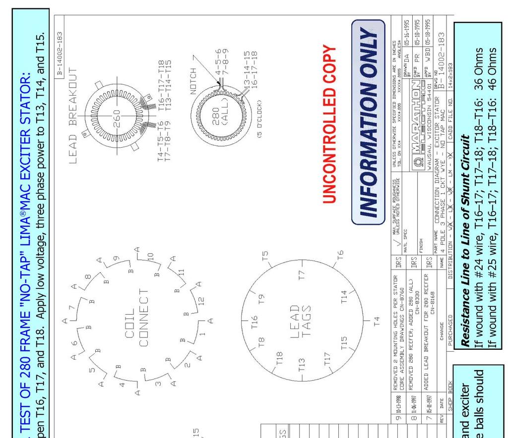
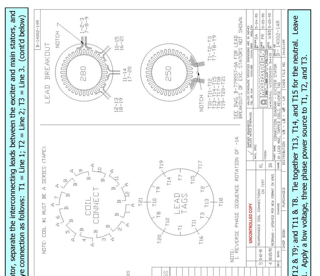
1 SERVICE SHOP NOTES LIMA MAC SELF VOLTAGE REGULATED GENERATORS Troubleshooting Tips Symptom: Engine bogs down or stalls even at no load. Problem: Main stator has one or more taps wound or connected incorrectly. (99% probability). This problem is only seen with generators having taps on their main stator coils. It is not seen with the newer No Tap LIMA MAC designs. Solution: Use ohmmeter to check the resistance between the leads. 12 Lead Generator Procedure, Reference Connection Diagram : Check resistance from T13-T4. It should be some small number. Then check from T4-T16. It should be a little bit smaller or about the same if not easily detectable. Then check T13-T16. This should be almost zero. If T16-T4 is almost zero, swap the lead numbers from T13 and T16. Repeat the procedure for the other six sets of coils and leads. If the reading from T4-T16 is nearly equal to T4-T13, the internal connection between coil one and four is wrong. It must be broken and corrected. Repeat the procedure for the other six sets of coils and leads. 10 Lead Generator Procedure, Reference Connection Diagram : Check resistance from T10-T4. It should be some small number. Then check from T4-T16. It should be a little bit smaller or about the same if not easily detectable then check T10-T16. This should be almost zero. If T16-T4 is almost zero, swap the lead numbers from T10 and T16. Repeat the procedure for the other six sets of coils and leads. If the reading from T4-T16 is nearly equal to T4-T10, the internal connection between coil one and four is wrong. It must be broken and corrected. Repeat the procedure for the other six sets of coils and leads. Comment: It is not necessary for the conduct of this procedure to have a meter that is accurate for very small resistances. The actual value of specific resistances is not needed here. What is required, is to measure is the relative difference in values. 1
2 Symptom: No voltage Problem: Flash the field. See restoring residual magnetism procedures on page 4. Assuming the field was flashed and there are no defective diodes, the most common problem after rewinding is the wrong phase sequence on one or both stators. In rare cases, the diodes are all in working order but there can be a poor connection on the rectifier assembly. Check all connections for corrosion. Solution: Swap lead numbers from two phases on one stator only. The main and exciter stator must have the opposite phase sequence to generate voltage. See the phase sequence reversal procedure detailed on pages 5 and 6 below. Symptom: Good voltage but one or more tapped coils gets hot under load. Problem: The most common problem is swapping the main lead with the tap lead next to it. They both come out of the same slot and are easily mixed up. The tapped turn(s) are designed to carry no load shunt current only. If the leads are swapped, the tap carries shunt current and load current. This causes the tap to overheat. Example: See Example under "Engine bogs down". Solution: If the resistance from T4-T13 is less than T4-T16, then swap T13 & T16. Check and repeat for all other groups. Symptom: Problem: Solution: Good voltage but one or more tapped coils gets hot without any load. Poor connection to all strands used for tapped coil. See "Connection" directions. Symptom: Good voltage no load but very low voltage under full load. Problem: Assuming there is no exciter damage or defect, the most likely cause is incorrect main stator coil insertion. Solution: See Coil Insertion directions. Rewinding Tips For Tapped LIMA MAC Generators Coil Winding The taps should be the specified number of turns (usually 1 or 2) away from the start or end of the coil group. 250 frames have taps at the end of the coils and all others have taps at the beginning of the coils. Only the first or last coil of the coil group should be tapped. Taps are typically made with a small twist in the wire while winding the coils. 2
3 Coil Insertion Using either , or as a reference, the coil insertion can be seen using the "Coil Connect" circle. Tapped coils have a "C" to denote the tap. Standard coils have "A" & "B" ends only. The "A" side of the coils lie in the bottom of the slot toward the "outside" of the core. The "B" side of the coils lie on top of another coil in the slot toward the "inside" of the core. One side of the tapped coil occupies the same slot as the "B" end and the other side is four slots away from the "A" end. The tap can be made anywhere between these two points. Diagram and -134, used for 250 LIMA MAC only, have the taps on the opposite side. Using -31 instead of -133 on a 250 LIMA MAC may result in low voltage under load. Viewing the "Coil Connect" circle as shown, the coils are inserted in a counter-clockwise (CCW) direction. The "A" side is inserted first in a CCW direction. Coil end "A" is in the last slot to be inserted. The "B" side is then inserted. After insertion, coil ends "A" & "B" must be at the outer edges of the coil group. If they are inserted to the inside of the coil group, the unit may have low voltage under load. See Diagram 1. Inserting the coils in a clockwise direction is acceptable if done consistently. It may result in a reversed phase sequence, though. DIAGRAM 1 LIMA MAC MAIN STATOR COIL INSERTION DIAGRAM CORRECT METHOD Slots End "A" End "B" INCORRECT METHOD Slots End "A" End "B" Connections Coils are to be connected as shown in the "Connect Table". All coil ends and leads on the same line are connected together. Refer to the "Coil Connect" circle for coil numbers. The "Lead Tag" circle is a physical representation of the lead locations after connecting but before lacing. It is used to speed connect time but the table contains all necessary information. Electrically they will be as shown in the schematic diagram. The tap lead must be electrically connected to all strands in the turn. If two strands of magnet wire are used per turn, the lead must be connected to both of them. 3
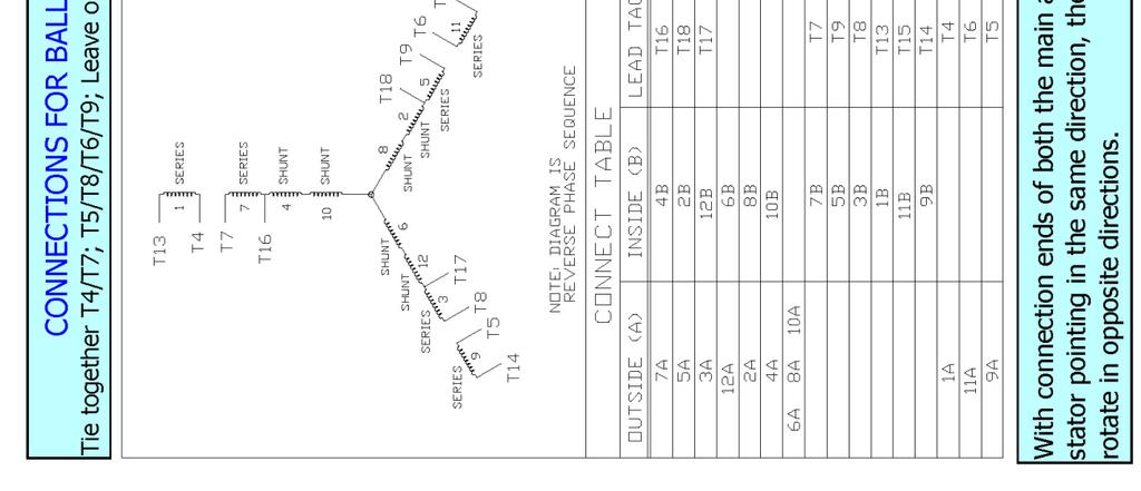
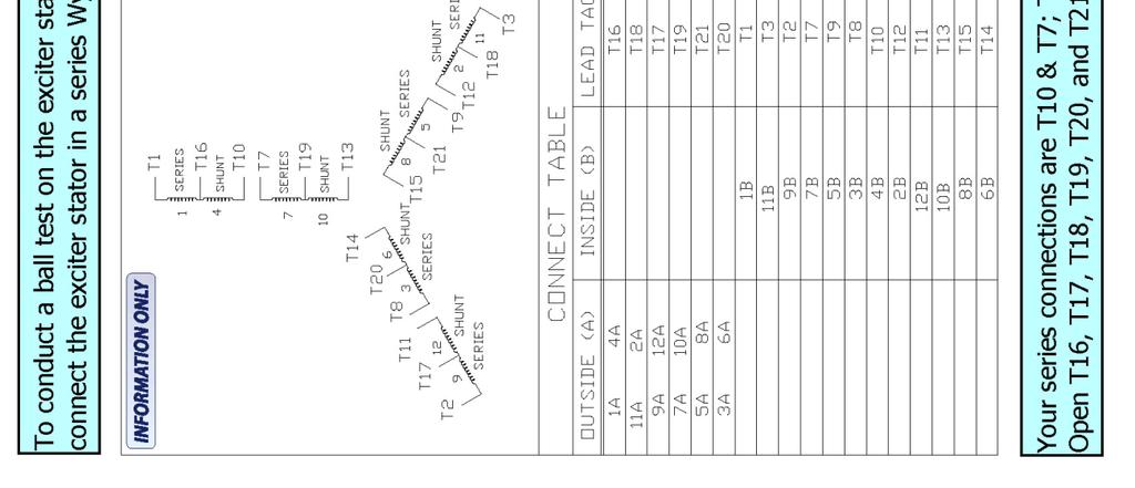
4 Restoring Residual Magnetism The current necessary to magnetize the alternator field during operation is obtained from the exciter. Initially, upon starting the unit, voltage is induced into the main stator (armature) by the flux across the air gap supplied by the permanent magnets embedded in the poles of the main rotor. Current then flows through interconnecting leads to the shunt portion of the exciter stator which induces current in the exciter rotor. This current is then rectified to DC excitation current by the rotating rectifier, and fed to the main field windings via the main rotor leads further strengthening the main field until rated voltage is reached. The residual magnetism contained in the field poles of the main rotor may be lost or severely weakened when the unit is disassembled for rewinding or other service operation. Should the generator fail to build up voltage after being reassembled, a momentary short circuit of any two generator output leads while the unit is running at rated speed should be sufficient to correct this condition. This action is termed "Flashing the Field". If the voltage does not build up with the above procedure, an alternate method may be used. Apply either an alternating or direct current voltage of from 24 to 30 volts to any two generator output leads. (Again - this procedure is conducted with the generator running at rated speed) Do not make a firm connection, but rather touch the leads together until the generator voltage begins to rise and then remove. It is suggested that a 30 ampere fuse be inserted in the supply voltage circuit to prevent any damage in case the build-up power supply voltage is not removed quickly enough. Start the generator and observe voltage build-up. Re-flash field if generator voltage does not build up. Verify that generator speed is at, or slightly above rated nameplate speed. Ball Testing of Stator Windings A ball test is simply another method of testing a stator winding to check for proper connections. The equipment consists of a large steel ball usually 1 to 2 inches in diameter. The diameter should be slightly larger than the distance between two adjacent stator slots. Sometimes, an inner or outer race of a ball bearing is used. The winding is usually connected in the high voltage wye connection, and a reduced voltage (about voltage) is applied to the output leads. The ball or race is then placed on the inside of the stator core. If the completed winding has been done properly, the ball will spin around the inside of the core at an even or uniform rate. If the winding is improperly connected, the movement of the ball will be erratic, or perhaps no movement will occur. 4
5 Reversing the Phase Sequence of a Rewound Stator. There have been many instances where a repair facility will rewind either a main stator or an exciter stator on a LIMA MAC generator, and then not be able to generate a voltage at the terminals during test running. In almost every case of this nature, the problem is either in a loss of residual magnetism, or with the phase sequence of the rewound stator. The phase sequence of the exciter stator must be opposite to that of the main stator, or the unit will not build up voltage. To correct an improper phase sequence problem, you will have to reverse the phase sequence of the rewound stator. To reverse the phase sequence of a stator winding, all lead tags of one phase of the stator will be switched with the leads the next phase, and then these renumbered leads will be connected to matching numbered leads of the original (non-rewound) stator. If both stators have been re- wound, reverse tag only one stator. Suggestion: After a stator rewind, run a ball test on both stators once they are installed in the frame and inter-connected. The ball in the main stator must rotate in the opposite direction to that of the exciter stator. If rotation is the same for both stators, reverse tag using the procedures below, and re-connect before preceding with installing the rotor assembly in generator. A. Reverse tagging of the main stator of a 12 lead LIMA MAC generator. Break apart the connections of leads T13, T16, T19, T22; and T14, T17, T20, T23. Working only on the leads of the main stator: Physically re-tag lead T13 - T14, and T14 - T13; T16 - T17, and T17 - T16; T19 - T20, and T20 - T19: T22 - T23, and T23 - T22. Leads T4, T5, T10, and T11 are out put leads. Re-tag T4 - T5, and T5 - T4; T10 - T11, and T11 -T10. You have now reversed the phase sequence of the exciter stator. Re-interconnect these leads to the main stator leads, re-install the splice insulation, bundle the entire group of interconnecting leads as before. B. Reverse tagging of the main stator of a 10 lead LIMA MAC generator. Break apart the connections of leads T10, T16, T13, T19; and T11, T17, T14, T20. Working only on the leads of the main stator: Physically re-tag lead T10 - T11, and T11 - T10: T16 -T17 and T17 - T16: T13 - T14 and T14 -T13: T19 - T20 and T20 -T19. Since load leads T4 and T5 are output leads, simply swap their tags to make T4 become T5, and T5 to become T4. You have now reversed the phase sequence of the main stator. Re-interconnect these leads to the exciter stator leads, re-install the splice insulation, bundle the entire group of interconnecting leads as before. C. Reverse tagging of the main stator of a 10 lead NO-TAP LIMA MAC generator. Break apart the connections for T4, T6, T7. T9, T13, T15, T16, T18. Working only on the leads of the exciter stator: Physically retag: T7-T9, T13-T15, T16-T18. Since load leads T4 and T6 are output leads, simply swap their tags to make T4 become T6, and T6 to become T4. You have now reversed the phase sequence of the main stator. Re-interconnect these leads to the exciter stator leads, re-install the splice insulation, bundle the entire group of interconnecting leads as before. Testing A, B, or C: Connect the generator output leads for the proper connection and retest. Note: You may need to flash the field to achieve voltage build up after this procedure. 5
6 6
7 7
8 8
9 9
Pretest Module 21 Units 1-4 AC Generators & Three-Phase Motors
 Pretest Module 21 Units 1-4 AC Generators & Three-Phase Motors 1. What are the two main parts of a three-phase motor? Stator and Rotor 2. Which part of a three-phase squirrel-cage induction motor is a
INTRODUCTION Principle
 DC Generators INTRODUCTION A generator is a machine that converts mechanical energy into electrical energy by using the principle of magnetic induction. Principle Whenever a conductor is moved within a
Historical Development
 TOPIC 3 DC MACHINES DC Machines 2 Historical Development Direct current (DC) motor is one of the first machines devised to convert electrical power into mechanical power. Its origin can be traced to the
ROTATING MAGNETIC FIELD
 Chapter 5 ROTATING MAGNETIC FIELD 1 A rotating magnetic field is the key to the operation of AC motors. The magnetic field of the stator is made to rotate electrically around and around in a circle. Stator
UNIT 2. INTRODUCTION TO DC GENERATOR (Part 1) OBJECTIVES. General Objective
 OBJECTIVES. General Objective") DC GENERATOR (Part 1) E2063/ Unit 2/ 1 UNIT 2 INTRODUCTION TO DC GENERATOR (Part 1) OBJECTIVES General Objective : To apply the basic principle of DC generator, construction principle and types of DC generator.
DC GENERATOR (Part 1) E2063/ Unit 2/ 1 UNIT 2 INTRODUCTION TO DC GENERATOR (Part 1) OBJECTIVES General Objective : To apply the basic principle of DC generator, construction principle and types of DC generator.
Most home and business appliances operate on single-phase AC power. For this reason, singlephase AC motors are in widespread use.
 Chapter 5 Most home and business appliances operate on single-phase AC power. For this reason, singlephase AC motors are in widespread use. A single-phase induction motor is larger in size, for the same
ECEg439:-Electrical Machine II
 ECEg439:-Electrical Machine II 2.2 Main Structural Elements of DC Machine Construction of DC Machines A DC machine consists of two main parts 1. Stationary Part (Stator):-It is designed mainly for producing
TROUBLESHOOTING GENERATOR UNITS
 TROUBLESHOOTING GENERATOR UNITS Figure 3.17 Troubleshooting Flow Chart For Direct Excited (Brush Type) Generators or later. 68 Troubleshooting Direct Excited (Brush Type) Generators Refer to Figure 3.17
BELT-DRIVEN ALTERNATORS
 CHAPTER 13 BELT-DRIVEN ALTERNATORS INTRODUCTION A generator is a machine that converts mechanical energy into electrical energy using the principle of magnetic induction. This principle is based on the
Contacts The moveable contact, which is the one affected by the armature is sometimes referred to as the hinge contact.
 Relays & Wiring 101 Basically, a relay is an electrically operated, remotely controlled switch. A simple electromagnetic relay is an adaptation of an electromagnet. It consists of a coil of wire surrounding
EXPERIMENT 19. Starting and Synchronizing Synchronous Machines PURPOSE: BRIEFING: To discover the method of starting synchronous motors.
 EXPERIMENT 19 Starting and Synchronizing Synchronous Machines PURPOSE: To discover the method of starting synchronous motors. BRIEFING: When three-phase is applied to the stator of a three-phase motor,
Basic Motor Theory. Introduction
 Basic Motor Theory Introduction It has been said that if the Ancient Romans, with their advanced civilization and knowledge of the sciences, had been able to develop a steam motor, the course of history
DC Series Motors by Thomas E. Kissell Industrial Electronics, Second Edition, Prentice Hall PTR
 Site Help Search NI Developer Zone DC Series Motors by Thomas E. Kissell Industrial Electronics, Second Edition, Prentice Hall PTR Back to Document Table of Contents: Series Motor Diagram Series Motor
Principles of Electrical Engineering
 D.C GENERATORS Principle of operation of D.C machines, types of D.C Generators, e.m.f equation of D.C Generator, O.C.C of a D.C Shunt Generator, Load characteristics of D.C.Generators GENERATOR PRINCIPLE:
C627, C628, C631, C656, C657, C658, C671 and C680 Alternator Troubleshooting Guide
 C627, C628, C631, C656, C657, C658, C671 and C680 Alternator Troubleshooting Guide Hazard Definitions These terms are used to bring attention to presence of hazards of various risk levels or to important
MOTORS. Part 2: The Stepping Motor July 8, 2015 ELEC This lab must be handed in at the end of the lab period
 MOTORS Part 2: The Stepping Motor July 8, 2015 ELEC 3105 This lab must be handed in at the end of the lab period 1.0 Introduction The objective of this lab is to examine the operation of a typical stepping
The Wound-Rotor Induction Motor Part I
 Experiment 1 The Wound-Rotor Induction Motor Part I OBJECTIVE To examine the construction of the three-phase wound-rotor induction motor. To understand exciting current, synchronous speed and slip in a
About this Troubleshooting Document
 About this Troubleshooting Document This document lists the error codes that exist within the Precor software hierarchy. Each section will include a description of the error code being displayed and the
AC Motors vs DC Motors. DC Motors. DC Motor Classification ... Prof. Dr. M. Zahurul Haq
 AC Motors vs DC Motors DC Motors Prof. Dr. M. Zahurul Haq http://teacher.buet.ac.bd/zahurul/ Department of Mechanical Engineering Bangladesh University of Engineering & Technology ME 6401: Advanced Mechatronics
SHORT-STOP. Electronic Motor Brake Type G. Instructions and Setup Manual
 Electronic Motor Brake Type G Instructions and Setup Manual Table of Contents Table of Contents Electronic Motor Brake Type G... 1 1. INTRODUCTION... 2 2. DESCRIPTION AND APPLICATIONS... 2 3. SAFETY NOTES...
N1233 Series Troubleshooting Guide for N Alternator
 N1233 Series Troubleshooting Guide for N1233-2 Alternator Hazard Definitions These terms are used to bring attention to presence of hazards of various risk levels or to important information concerning
DC motor theory. Resources and methods for learning about these subjects (list a few here, in preparation for your research):
:") DC motor theory This worksheet and all related files are licensed under the Creative Commons Attribution License, version 1.0. To view a copy of this license, visit http://creativecommons.org/licenses/by/1.0/,
DC motor theory This worksheet and all related files are licensed under the Creative Commons Attribution License, version 1.0. To view a copy of this license, visit http://creativecommons.org/licenses/by/1.0/,
Water Temperature. GM LS Engine Gauges Installation Guide
 2650-1563-00 GM LS Engine Gauges Installation Guide Water Temperature For water temperature, there is a port located on the right side (passenger side) of the engine, in the cylinder head, past the last
 Motor Trouble-Shooting Chart Caution:. Disconnect power to the motor before performing service or maintenance.. Discharge all capacitors before servicing motor.. Always keep hands and clothing away from
CHAPTER THREE DC MOTOR OVERVIEW AND MATHEMATICAL MODEL
 CHAPTER THREE DC MOTOR OVERVIEW AND MATHEMATICAL MODEL 3.1 Introduction Almost every mechanical movement that we see around us is accomplished by an electric motor. Electric machines are a means of converting
SECTION 4 ELECTRIC MOTORS UNIT 17: TYPES OF ELECTRIC MOTORS UNIT OBJECTIVES UNIT OBJECTIVES 3/21/2012
 SECTION 4 ELECTRIC MOTORS UNIT 17: TYPES OF ELECTRIC MOTORS UNIT OBJECTIVES After studying this unit, the reader should be able to Describe the different types of open single-phase motors used to drive
Module 9. DC Machines. Version 2 EE IIT, Kharagpur
 Module 9 DC Machines Lesson 38 D.C Generators Contents 38 D.C Generators (Lesson-38) 4 38.1 Goals of the lesson.. 4 38.2 Generator types & characteristics.... 4 38.2.1 Characteristics of a separately excited
Comprehensive Technical Training
 Comprehensive Technical Training For Sugar Mills Staff on Operation & Maintenance of Baggase Based HP Cogeneration System Schedule: 10 th July to 13 th July, 2017 A.C. GENERATOR Topics Covered. Introduction.
9/7/2010. Chapter , The McGraw-Hill Companies, Inc. MOTOR CLASSIFICATION. 2010, The McGraw-Hill Companies, Inc.
 Chapter 2 MOTOR CLASSIFICATION 1 In general, motors are classified according to the type of power used (AC or DC) and the motor's principle of operation. AC DC Motor Family Tree 2 DC MOTOR CONNECTIONS
C.E. Niehoff & Co. C653/C653A and C625 Alternators Troubleshooting Guide NOTICE. Hazard Definitions. Battery Charge Volt and Amp Values
 C.E. Niehoff & Co. C653/C653A and C625 Alternators Troubleshooting Guide Hazard Definitions These terms are used to bring attention to presence of hazards of various risk levels or to important information
Bistable Rotary Solenoid
 Bistable Rotary Solenoid The bistable rotary solenoid changes state with the application of a momentary pulse of electricity, and then remains in the changed state without power applied until a further
Renewable Energy Systems 13
 Renewable Energy Systems 13 Buchla, Kissell, Floyd Chapter Outline Generators 13 Buchla, Kissell, Floyd 13-1 MAGNETISM AND ELECTROMAGNETISM 13-2 DC GENERATORS 13-3 AC SYNCHRONOUS GENERATORS 13-4 AC INDUCTION
Operation Construction Classification Applications. DC Motors
 Operation Construction Classification Applications DC Motors A DC Motor converts electrical energy into mechanical energy. Special applications where dc motors are used include: in steel mills, mines
ESO 210 Introduction to Electrical Engineering
 ESO 210 Introduction to Electrical Engineering Lectures-37 Polyphase (3-phase) Induction Motor 2 Determination of Induction Machine Parameters Three tests are needed to determine the parameters in an induction
Electronic Dynamo Regulator INSTRUCTION MANUAL. COPYRIGHT 2014 CLOVER SYSTEMS All Rights Reserved
 DRM TM DRM-HP TM Electronic Dynamo Regulator INSTRUCTION MANUAL COPYRIGHT 2014 CLOVER SYSTEMS All Rights Reserved INTRODUCTION The Clover Systems DRM is a state-of-the art all-electronic voltage and current
Figure 4.1.1: Cartoon View of a DC motor
 Problem 4.1 DC Motor MASSACHUSETTS INSTITUTE OF TECHNOLOGY Department of Electrical Engineering and Computer Science 6.007 Applied Electromagnetics Spring 2011 Problem Set 4: Forces and Magnetic Fields
INDUCTANCE FM CHAPTER 6
 CHAPTER 6 INDUCTANCE INTRODUCTION The study of inductance is a very challenging but rewarding segment of electricity. It is challenging because at first it seems that new concepts are being introduced.
Electronic Dynamo Regulator INSTRUCTION MANUAL. COPYRIGHT 2014 CLOVER SYSTEMS All Rights Reserved
 DRM TM DRM-HP TM Electronic Dynamo Regulator INSTRUCTION MANUAL COPYRIGHT 2014 CLOVER SYSTEMS All Rights Reserved INTRODUCTION The Clover Systems DRM is a state-of-the art all-electronic voltage and current
Unit 32 Three-Phase Alternators
 Unit 32 Three-Phase Alternators Objectives: Discuss the operation of a three-phase alternator. Explain the effect of rotation speed on frequency. Explain the effect of field excitation on output voltage.
EXPERIMENTAL VERIFICATION OF INDUCED VOLTAGE SELF- EXCITATION OF A SWITCHED RELUCTANCE GENERATOR
 EXPERIMENTAL VERIFICATION OF INDUCED VOLTAGE SELF- EXCITATION OF A SWITCHED RELUCTANCE GENERATOR Velimir Nedic Thomas A. Lipo Wisconsin Power Electronic Research Center University of Wisconsin Madison
Electrical Machines-I (EE-241) For S.E (EE)
 For S.E (EE)") PRACTICAL WORK BOOK For Academic Session 2013 Electrical Machines-I (EE-241) For S.E (EE) Name: Roll Number: Class: Batch: Department : Semester/Term: NED University of Engineer ing & Technology Electrical
PRACTICAL WORK BOOK For Academic Session 2013 Electrical Machines-I (EE-241) For S.E (EE) Name: Roll Number: Class: Batch: Department : Semester/Term: NED University of Engineer ing & Technology Electrical
26 SI HEAVY DUTY BRUSHLESS ALTERNATOR SERVICE MANUAL 1G-287 PRODUCT INFORMATION 1/98 26-SI ALTERNATOR 1G/287 4/96 PAGE
 26-SI ALTERNATOR G/287 4/96 PAGE G-287 PRODUCT INFORMATION /98 26 SI HEAVY DUTY BRUSHLESS ALTERNATOR SERVICE MANUAL 998 Delco Remy International Inc. All Rights Reserved. PAGE G-287 4/96 26-SI ALTERNATOR
THE BATTERY CHARGER OF RON PUGH
 THE BATTERY CHARGER OF RON PUGH THANKS IS DUE TO RON PUGH WHO HAS KINDLY SHARED THE CONSTRUCTION DETAILS OF HIS VERY SUCCESSFUL BATTERY CHARGER WHICH IS COP=13 WHEN OPERATING AT 24 VOLTS. IF YOU DECIDE
A Practical Guide to Free Energy Devices
 A Practical Guide to Free Energy Devices Part PatD20: Last updated: 26th September 2006 Author: Patrick J. Kelly This patent covers a device which is claimed to have a greater output power than the input
MAGNAMAX DVR DIGITAL VOLTAGE REGULATOR
 MAGNAMAX DVR DIGITAL VOLTAGE REGULATOR TECHNICAL MANUAL MODEL DVR 2000 AND DVR 2000C FIGURE 1 - FRONT AND REAR VIEW OF VOLTAGE REGULATOR...4 SECTION 1- INTRODUCTION...5 GENERAL DESCRIPTION...5 SPECIFICATIONS...5
Installation Instructions
 Quick-Mount Visual Instructions for Mechanical Installation Quick-Mount Visual Instructions 1. Rotate the damper to its failsafe position. If the shaft rotates counterclockwise, mount the CCW side of the
A2P Single Phase Automatic Industrial Battery Charger
 A2P Single Phase Automatic Industrial Battery Charger Featuring 205B Konrad Cres., Markham, ON, L3R 8T9 www.chargers.ca Building Canada s toughest battery chargers for over a century. Congratulations on
1 THE WOLVERTON SYSTEM OF TRAIN LIGHTING.
 1 THE WOLVERTON SYSTEM OF TRAIN LIGHTING. The Wolverton equipment is a single battery system utilising a plain shunt wound dynamo. The dynamo is controlled by an automatic field regulator which senses
ECE 325 Electric Energy System Components 6 Three Phase Induction Motors. Instructor: Kai Sun Fall 2016
 ECE 325 Electric Energy System Components 6 Three Phase Induction Motors Instructor: Kai Sun Fall 2016 1 Content (Materials are from Chapters 13-15) Components and basic principles Selection and application
INDUCTION MOTOR. There is no physical electrical connection to the secondary winding, its current is induced
 INDUCTION MOTOR INTRODUCTION An induction motor is an alternating current motor in which the primary winding on one member (usually the stator) is connected to the power source and a secondary winding
1G SI 34 SI HEAVY DUTY BRUSHLESS ALTERNATOR SERVICE MANUAL Delco Remy International Inc. All Rights Reserved.
 G-500 PRODUCT INFORMA ORMATION /98 33 SI 34 SI HEAVY DUTY BRUSHLESS ALTERNATOR SERVICE MANUAL 998 Delco Remy International Inc. All Rights Reserved. PAGE 33/34 SI ALTERNATOR FEATURES SPECIFICATIONS: MAXIMUM
ELECTRICAL. Contents - Wiring Diagrams
 Contents - Wiring Diagrams T-Bar (Floating Deck - Hydro)............................................ 8-16 T-Bar (Fixed Deck - Gear)............................................... 8-17 T-Bar (Fixed Deck
Note 8. Electric Actuators
 Note 8 Electric Actuators Department of Mechanical Engineering, University Of Saskatchewan, 57 Campus Drive, Saskatoon, SK S7N 5A9, Canada 1 1. Introduction In a typical closed-loop, or feedback, control
Single-Phase AC Induction Squirrel Cage Motors. Permanent Magnet Series Wound Shunt Wound Compound Wound Squirrel Cage. Induction.
 FAN ENGINEERING Information and Recommendations for the Engineer Twin City Fan FE-1100 Single-Phase AC Induction Squirrel Cage Motors Introduction It is with the electric motor where a method of converting
INDEX Section Page Number Remarks
 INDEX Section Page Number Remarks Synchronous Alternators 2 4 General Fault Finding Capacitors 5 6 Fault Finding & Testing Diodes,Varistors, EMC capacitors & Recifiers 7 10 Fault Finding & Testing Rotors
Portable Generator Familiarization & Troubleshooting Guide Section 3 Generator Diagnostics and Adjustments
 Figure 3.31 Troubleshooting Flow Chart For (Brush Type) Generators With Two-Board Regulation 76 Troubleshooting Two Board Regulation Generators (Brush Type) Refer to Figure 3.31. Test 1: Check (AC) Frequency
The Starter motor. Student booklet
 The Starter motor Student booklet The Starter motor - INDEX - 2006-04-07-13:20 The Starter motor The starter motor is an electrical motor and the electric motor is all about magnets and magnetism: A motor
Charles Flynn s Permanent Magnet Motor.
 Charles Flynn s Permanent Magnet Motor. Patent US 5,455,474 dated 3rd October 1995 and shown in full in the Appendix, gives details of this interesting design. It says: This invention relates to a method
WARNING This manual should only be used by a qualified Service Technician. FinishPro 390/395 Airless/Air-Assisted Sprayer Repair Electrical Manual
 FinishPro 390/395 Airless/AirAssisted Sprayer Repair Electrical Manual First choice when quality counts. Rev. B 10/11 /07 FinishPro 395 3.00 ti9026a Red Yel Yel Air Hose Connection FinishPro 390 Exhaust
17429X.00 SERIES MODELS:
 LEESON ELECTRIC MOTORS, GEARMOTORS AND DRIVES R User s Manual 17429X.00 SERIES MODELS: 174298.00 174299.00 PWM REGENERATIVE DC TO DC DRIVES II Table of Contents 17429X.00 Drives...............................................................
 YNCHRONIZER AUTOMATIC SYNCHRONIZE TROUBLESHOOTING GUIDE SOLENOID (MODEL 1750) RELAY ASSEMBLY LIMIT SWITCH ENGINE CABLE CABLE TO ENGINE THROTTLE RED COLLAR ADJUST LIMIT SWITCH OPERATION BRIDGE CABLE CONTROL
A Practical Guide to Free Energy Devices
 A Practical Guide to Free Energy Devices Part PatD11: Last updated: 3rd February 2006 Author: Patrick J. Kelly Electrical power is frequently generated by spinning the shaft of a generator which has some
AC MOTOR TYPES. DESCRIBE how torque is produced in a single-phase AC motor. EXPLAIN why an AC synchronous motor does not have starting torque.
 Various types of AC motors are used for specific applications. By matching the type of motor to the appropriate application, increased equipment performance can be obtained. EO 1.5 EO 1.6 EO 1.7 EO 1.8
XR500B Universal Voltage Regulator
 XR500B Universal Voltage Regulator The XR500B is a unique voltage regulator that is designed specifically for Professional Electrical Generator Service and Repair Technicians. The XR500B incorporates patented
A - Add New Information C - Change Existing Information D - Delete Information. Page 7. Delete the fourth paragraph beginning CAUTION
 ABB Effective: November 1990 This Addendum Supersedes all Previous Addenda Addendum to Instruction Leaflet 41-137.3H Type KRD-4 Directional Overcurrent Ground Relay A - Add New Information C - Change Existing
CHAPTER 4 HARDWARE DEVELOPMENT OF DUAL ROTOR RADIAL FLUX PERMANENT MAGNET GENERATOR FOR STAND-ALONE WIND ENERGY SYSTEMS
 66 CHAPTER 4 HARDWARE DEVELOPMENT OF DUAL ROTOR RADIAL FLUX PERMANENT MAGNET GENERATOR FOR STAND-ALONE WIND ENERGY SYSTEMS 4.1 INTRODUCTION In this chapter, the prototype hardware development of proposed
Short Term Course On Hydropower Development Engineering (Electrical) for Teachers of Polytechnics in Uttarakhand L33-2
 for Teachers of Polytechnics in Uttarakhand L33-2") Short Term Course On Hydropower Development Engineering (Electrical) for Teachers of Polytechnics in Uttarakhand ( July 14-18, 2007) Lecture on L33-2 By S.N.Singh Senior Scientific officer ALTERNATE HYDRO
Short Term Course On Hydropower Development Engineering (Electrical) for Teachers of Polytechnics in Uttarakhand ( July 14-18, 2007) Lecture on L33-2 By S.N.Singh Senior Scientific officer ALTERNATE HYDRO
AQA GCSE Physics. 55 minutes. 55 marks. Q1 to Q4 to be worked through with tutor. Q5 to Q7 to be worked through independently.
 AQA GCSE Physics Magnetism & Electromagnetism 4.7.. - 4.7.2.: Magnets & Electromagnets Name: Class: Date: Time: 55 minutes Marks: 55 marks Comments: Q to Q4 to be worked through with tutor. Q5 to Q7 to
PHY 152 (ELECTRICITY AND MAGNETISM)
") PHY 152 (ELECTRICITY AND MAGNETISM) ELECTRIC MOTORS (AC & DC) ELECTRIC GENERATORS (AC & DC) AIMS Students should be able to Describe the principle of magnetic induction as it applies to DC and AC generators.
PHY 152 (ELECTRICITY AND MAGNETISM) ELECTRIC MOTORS (AC & DC) ELECTRIC GENERATORS (AC & DC) AIMS Students should be able to Describe the principle of magnetic induction as it applies to DC and AC generators.
Electric motor testing
 Electric motor testing MOTOR (MODELS EJ4-4001 AND EJ8-4001A) 23 GENERAL INFORMATION The vehicle is equipped with a 48-volt DC, shunt-wound, reversible traction motor. The shunt-wound motor is designed
VoltPro VP4 Automatic Voltage Regulator
 VoltPro VP4 Automatic Voltage Regulator The VoltPro VP4 Automatic Voltage Regulator is an affordable generator voltage regulator that is designed for the consumer market and can replace many popular voltage
MD10. Engine Controller. Installation and User Manual for the MD10 Engine Controller. Full Version
 MD10 Engine Controller Installation and User Manual for the MD10 Engine Controller. Full Version File: MartinMD10rev1.4.doc May 16, 2002 2 READ MANUAL BEFORE INSTALLING UNIT Receipt of shipment and warranty
To discover the factors affecting the direction of rotation and speed of three-phase motors.
 EXPERIMENT 12 Direction of Rotation of Three-Phase Motor PURPOSE: To discover the factors affecting the direction of rotation and speed of three-phase motors. BRIEFING: The stators of three-phase motors
DC MOTOR MAINTENANCE ALL ELECTRIC LIFT TRUCKS PART NO SRM 294
 DC MOTOR MAINTENANCE ALL ELECTRIC LIFT TRUCKS PART NO. 897076 620 SRM 294 SAFETY PRECAUTIONS MAINTENANCE AND REPAIR When lifting parts or assemblies, make sure all slings, chains, or cables are correctly
Just what is an alternator?
 Just what is an alternator? An alternator is the device used to produce the electricity the car needs to run and to keep the battery charged. The battery is the heart of your electrical system. But you
 APGENCO/APTRANSCO Assistant Engineer Electrical Previous Question Papers Q.1 The two windings of a transformer is conductively linked. inductively linked. not linked at all. electrically linked. Q.2 A
Automatic taper of charge rate for superior battery life through good equalization of cells and low water use rate.
 FEATURES Automatic taper of charge rate for superior battery life through good equalization of cells and low water use rate. Silicon diodes with inherent surge protection operated at a conservative percentage
Pretest Module 21 Unit 4 Single-Phase Motors
 Pretest Module 21 Unit 4 Single-Phase Motors 1. What are the four main components of a single-phase motor? Rotor, stator, centrifugal switch, end bells and bearings 2. How is a rotating field created in
CHARGING SYSTEM 8C - 1 CHARGING SYSTEM CONTENTS
 TJ CHARGING SYSTEM 8C - 1 CHARGING SYSTEM CONTENTS page DESCRIPTION AND OPERATION BATTERY TEMPERATURE SENSOR... 2 CHARGING SYSTEM OPERATION... 1 ELECTRONIC VOLTAGE REGULATOR... 2 GENERATOR... 1 DIAGNOSIS
SUREPOWR TM SERIES -SURE 49 FIELD INSTALLATION INSTRUCTIONS
 SUREPOWR TM SERIES -SURE 49 FIELD INSTALLATION INSTRUCTIONS Safety First In the maintenance and operation of mechanical equipment, SAFETY is the basic factor which must be considered at all times. Through
EXPERIMENT 2 THREE PHASE INDUCTION MOTOR, PART 1
 University f Jordan School of Engineering Department of Mechatronics Engineering Electrical Machines Lab Eng. Osama Fuad Eng. Nazmi Ashour EXPERIMENT 2 THREE PHASE INDUCTION MOTOR, PART 1 OBJECTIVES To
Table No. 1 provides a means of identifying the various alternator systems. Note: All output figures are rated at 3600 RPM. TABLE NO.
 The alternator systems installed on Briggs & Stratton Intek OHV-Twin Cylinder Engines can easily be identified by the color of the stator output wires and the connector. Table No. 1 provides a means of
Shape - Typical designs with sector angles of pi/2 [90 degrees], and 2pi/3 [120 degrees] are shown below.
![Shape - Typical designs with sector angles of pi/2 [90 degrees], and 2pi/3 [120 degrees] are shown below.](/thumbs/72/67263789.jpg "Shape - Typical designs with sector angles of pi/2 [90 degrees], and 2pi/3 [120 degrees] are shown below.") Sector Torus Cores Started 01 Jun 012 By Newton E. Ball Definitions - Torus - Restricted to Circular Torus, the solid shape formed by the rotation of a circular area, about an axis that is external to
Sector Torus Cores Started 01 Jun 012 By Newton E. Ball Definitions - Torus - Restricted to Circular Torus, the solid shape formed by the rotation of a circular area, about an axis that is external to
Page 1 of 1 ALTERNATORS. Overview. Intek TM V-Twin Cylinder OHV Engine Service Manual Version 1.0. Copyright 1999 by Briggs and Stratton Corporation
 Overview Alternator Identification Page 1 of 3 The alternator systems installed on Briggs & Stratton Intek V-Twin Cylinder OHV Engines can easily be identified by the color of the stator output wires and
Komodo Hobby. Building Instruction & Manual. KH -283 Outrunner Motor Kit Version 2 (Stick Style)
") Building Instruction & Manual KH -283 Outrunner Motor Kit Version 2 (Stick Style) Introduction Congratulations on your purchase of KH-283 Outrunner Motor Kit Version 2. KH-283 V.2 is a modified motor kit
Building Instruction & Manual KH -283 Outrunner Motor Kit Version 2 (Stick Style) Introduction Congratulations on your purchase of KH-283 Outrunner Motor Kit Version 2. KH-283 V.2 is a modified motor kit
LJ20 Distributor - Disassembly Inspection Repair
 LJ20 Distributor - Disassembly Inspection Repair Old Codger New To Old Suzuki Jeeps The odometer on this 1972 LJ20 indicated the distributor had less than 10,000 miles of wear but during that time it had
Electrical Machines -II
 Objective Type Questions: 1. Basically induction machine was invented by (a) Thomas Alva Edison (b) Fleming (c) Nikola Tesla (d) Michel Faraday Electrical Machines -II 2. What will be the amplitude and
Installation Instructions
 Quick-Mount Visual Instructions for Quick-Mount Visual Instructions 1. Rotate the damper to its failsafe position. If the shaft rotates counterclockwise, mount the CCW side of the actuator out. If it rotates
Chapter 17 Notes. Magnetism is created by moving charges.
 Chapter 17 Notes Section 17.1 Electric Current and Magnetism Hans Christian Øersted (1819), a Danish physicist and chemist - compass needle near a wire circuit and with current flowing through the wire,
STANDARD AND GROUND SWITCHED APPLICATIONS
 SNOWDOGG LIGHT REFERENCE STANDARD AND GROUND SWITCHED APPLICATIONS GENERAL REFERENCE SNOWDOGG LIGHT REFERENCE GENERAL REFERENCE 3 TROUBLESHOOTING GUIDES/PROCEDURES 6 CONNECTOR REFERENCE 12 ADAPTER HARNESS
ALTERNATOR - CHRYSLER 40/90-AMP & 50/120 AMP
 ALTERNATOR - CHRYSLER 40/90-AMP & 50/120 AMP 1988 Chrysler LeBaron Convert/Coupe 1988 ELECTRICAL Chrysler Motors 40/90 & 50/120 Amp Alternators FWD Models DESCRIPTION The charging system consists of an
ALTERNATOR - BOSCH 35/75-AMP & 40/90-AMP
 ALTERNATOR - BOSCH 35/75-AMP & 40/90-AMP 1988 Chrysler LeBaron Convert/Coupe 1988 ALTERNATORS & REGULATORS Chrysler Motors - Bosch 35/75 & 40/90 Amp Alternator All Models DESCRIPTION The charging system
C802/C802D/C802TD/C820 Alternators Troubleshooting Guide
 C802/C802D/C802TD/C820 Alternators Troubleshooting Guide Hazard Definitions These terms are used to bring attention to presence of hazards of various risk levels or to important information concerning
INSTRUCTION MANUAL FOR. VOLTAGE REGULATOR Model: APR Part Number:
 INSTRUCTION MANUAL FOR VOLTAGE REGULATOR Model: APR 125-5 Part Number: 9 1688 00 100 Publication Number: 9 1688 00 990 Revision H: 07/2001 CONTENTS SECTION 1 GENERAL INFORMATION...1-1 DESCRIPTION... 1-1
Tachometer (RPM Feedback) General
 General") Tachometer (RPM Feedback) General The force of magnetic fields interacting drives all electric motors. How the magnetic field is created on the moving rotor determines the type of control required on the
Tachometer (RPM Feedback) General The force of magnetic fields interacting drives all electric motors. How the magnetic field is created on the moving rotor determines the type of control required on the
2015 EDITION SUBMERSIBLE MOTORS AIM MANUAL. APPLICATION INSTALLATION MAINTENANCE 60 Hz, Single-Phase and Three-Phase Motors. franklinwater.
 0 EDITION AIM MANUAL SUBMERSIBLE MORS APPLICATION INSTALLATION 60 Hz, Single-Phase and Three-Phase Motors franklinwater.com All Motors System Troubleshooting Motor Does Not Start A. No power or incorrect
Period 16 Activity Sheet: Motors and Generators
 Name Section Period 16 Activity Sheet: Motors and Generators Activity 16.1: How Are Electric Motors and Generators Related? a) Generators. 1) Attach a hand-cranked generator to a small motor and turn the
VoltPro VPBF8 Automatic Battery Flashing Module This Manual Covers Both VPBF8-12 and VPBF8-24 Models
 VoltPro VPBF8 Automatic Battery Flashing Module This Manual Covers Both VPBF8-12 and VPBF8-24 Models The VoltPro VPBF8 Automatic Battery Flashing Module is an affordable add-on module for VoltPro VP4,
EEE3441 Electrical Machines Department of Electrical Engineering. Lecture. Introduction to Electrical Machines
 Department of Electrical Engineering Lecture Introduction to Electrical Machines 1 In this Lecture Induction motors and synchronous machines are introduced Production of rotating magnetic field Three-phase
Inspection Testing Repair
 Inspection Testing Repair Generator Technical Services 1810 Blackwell Lane Penascola, FL 32514 Phone (850) 471-1101 Fax (850) 471-1104 Email: info@gentechservices.com Power Generation Generator Technical